ADIC SCALAR 24 Installation And Operation Manual
Intelligent storage
Hide thumbs
Also See for SCALAR 24:
- Installation and operation manual (176 pages) ,
- Error code list (4 pages) ,
- Installation and operating manual (84 pages)

Related Manuals for ADIC SCALAR 24


Summary of Contents for ADIC SCALAR 24
- Page 1 Scalar ® Installation and Operation Guide ADVANCED DIGITAL INFORMATION CORPORATION www.adic.com...
- Page 2 Further, ADIC Europe reserves the right to revise or change this publication without obligation on the part of ADIC Europe to notify any person or organization of such revision of change.
-
Page 3: Table Of Contents
Installing Scalar 24 Hardware........ - Page 4 What type of terminator is required? ..........34 Can I add an LTO-3 drive to a Scalar 24 LTO-1 or LTO-2 Library? ......34 Where are the drivers located? .
- Page 5 Set Library SCSI ID............82 Scalar 24 Installation and Operation Guide...
- Page 6 User Interface ..............83 Set Timeout.
- Page 7 Scalar 24 Error Messages ........
- Page 8 viii Contents...
-
Page 9: About This Guide And Your Product
This product is designed for processing magnetic tape cartridges. Any other application is not considered the intended use. ADIC will not be held liable for damage arising from unauthorized use of the product. The user assumes all risk in this aspect. -
Page 10: Other Documents You Might Need
More information about this product is available on the Customer Service Center website at www.adic.com/csc. The Customer Service Center contains a collection of information, including answers to frequently asked questions (FAQs). You can also access software, firmware, and drivers through this site. -
Page 11: Description
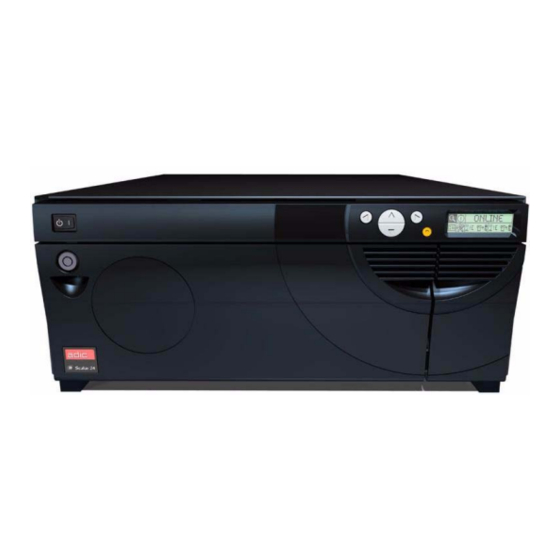
Description The Scalar 24 is designed to provide optimal density in both rackmount and desktop environments while offering features and functionality only found in mid-range libraries. The library can provide over one month of unattended backup and fits in only 4U (7 inches) of rack space. For more information on capacity, refer... -
Page 12: Features
24 Hour Fast Exchange. In the event your Scalar 24 needs to be serviced and you are unable to resolve the problem with the ADIC Technical Assistance Center, ADIC will provide you with a next business day advanced exchange to minimize down time. -
Page 13: Optional Features
Storage Area Network (SAN), provide Fibre Channel to SCSI connectivity or Gigabit Ethernet to SCSI connectivity. The available feature set depends on which SNC you integrate into your library. The Scalar 24 supports the SNC 4000 and the SNC 4501. -
Page 14: Interior Components
I/E Door Door for access to the I/E slot. The I/E feature allows you to import or export tape cartridges with the media access door locked. LCD and Keypad (operator The high-contrast LCD and keypad allow you to view the panel) operational status of the library, perform system configuration, and execute commands. -
Page 15: Rear Panel Components
ADIC Part Number (APN), the country of manufacture, and a patent number. Rear Panel Components The following graphics show the components located on the rear panel of your Scalar 24: AC Power Connector Receptacle for AC power cord. SCSI Connectors... -
Page 16: Drives
Drives Your Scalar 24 can be equipped with either one or two drives. The tape drives are packaged in a common drive module that is designed so that you can easily add an additional drive or replace a drive. For more... - Page 17 Never reset or power down your computer or Scalar 24 while a CAUTION function is in process or a tape is moving. The following diagram provides a representational view of media storage as it is laid out in a library configured for LTO media.
-
Page 18: Host Interface
The following diagram provides a representational view of media storage as it is laid out in a library configured for SDLT media. Host Interface The Scalar 24 is a target device and can be connected to hosts by using a Low Voltage Differential (LVD) SCSI bus or by using Fibre Channel. Description... -
Page 19: Native Fibre Connections
Terminator If the Scalar 24 is the last device on a SCSI chain, a terminator is required. The terminator attaches to the SCSI connector on the drive module. Be sure to use an LVD terminator that is SPI-3 compliant. For... -
Page 20: Scsi Cables
SCSI Cables Connect your Scalar 24 SCSI Library to the host by means of an LVD SCSI cable with an HD68 connector Cables of various lengths and connector types are available through ADIC to match your specific requirements. Typically, a host bus adaptor (HBA) has either an HD68 or VHDCI connection. SCSI cables connecting the host HBA to the library should not exceed 20 feet in length. -
Page 21: Getting Started
Scalar 24, below the right magazine. In order to see the serial number label, remove this magazine. Checking the Accessories Check to make certain that the following items are included with your Scalar 24 and that none of them are damaged: •... -
Page 22: Installing Scalar 24 Hardware
Scalar 24 uses a 68-pin LVD SCSI connector on the rear panel. • If your host computer’s SCSI connector is different from the one on the Scalar 24, obtain an adapter or a different cable. Consult your dealer or ATAC if you need help. -
Page 23: Connecting More Than One Scsi Library
Connecting More than One SCSI Library If you are connecting more than one Scalar 24 on the same SCSI channel, connect each unit to the previous unit with an additional shielded interface cable. It does not matter which SCSI connector on each Scalar 24 you connect the interface cable to. -
Page 24: Connecting To A Fibre Drive
• Ensure the cable is a 68-pin HD cable and is at least 2 feet (61 cm) in Note length. • Daisy-chain no more than two Scalar 24s or two drives together. Otherwise the data transfer rate may be reduced. Connecting to a Fibre Drive Each drive module in a fibre library has one duplex FC (Fibre Channel) connector on the back panel. -
Page 25: Connecting The Power Cord
ELECTRICAL OUTLET. HAZARDOUS VOLTAGES ARE PRESENT IN THE SOCKETS OF THE OUTLET. Plug the power cord into the AC receptacle on the rear panel of your Scalar 24. Ensure that the AC line cord from the library is plugged directly into CAUTION the socket. - Page 26 Removing Media on page 42. Media barcode labels can be viewed through the magazine window. Note Re-install the magazines into the Scalar 24. You need to push firmly to fully insert the magazines. Note Close the media access door. Refer to Bulk Load on page 102 for instructions on loading cartridges from the magazines into the rear slots.
-
Page 27: Setting Up Your Scalar 24
Setting up your Scalar 24 After you have set up your host computer, you need to configure your library. Your Scalar 24 provides you with the unique ability to set up the library using a Setup Wizard. The Setup Wizard guides you step-by- step through the setup process ensuring that all elements are configured in the proper order. -
Page 28: Installing Drivers For Windows 2000 And Windows Server 2003
2000 and Windows Server 2003 native backup, there is no special library driver required for the Scalar 24. The Scalar 24 can operate using the standard media changer driver provided with the Windows Removable Storage Manager (RSM). Windows will still try to locate a suitable driver using the Found New Hardware Wizard, so when this wizard opens, follow the instructions below to complete the setup. - Page 29 • LTO-1: IBM ULTRIUM-TD1 SCSI Sequential Device • LTO-2: IBM ULTRIUM-TD2 SCSI Sequential Device • LTO-3: IBM ULTRIUM-TD3 SCSI Sequential Device • SDLT-320: Quantum SDLT320 SCSI Sequential Drive • SDLT-600: SuperDLTtape (tm) SDLT600 Drive Scalar 24 Installation and Operation Guide...
- Page 30 Getting Started...
-
Page 31: Installing Optional Hardware
Installing an Additional Drive Your Scalar 24 comes with either one or two drives. If you have one drive, you can install an additional drive by following the procedure below. Your Scalar 24 can contain up to two drives. To replace an installed drive... - Page 32 From the rear of the Scalar 24, locate the available drive slot. Loosen the four thumbscrews on the cover plate and remove the cover plate. Store the cover plate in a convenient place. It is required for proper operation and cooling of the library if the optional drive is ever removed.
-
Page 33: Removing And Replacing A Drive
• If your Scalar 24 is attached to a SAN through an SNC, update the drive mapping, either by rebooting the SNC or by using the ADIC Management Console (AMC) to reset and rescan the appropriate SCSI channel. -
Page 34: Installing The Scalar 24 In A Rack
From the rear of the Scalar 24, locate the available RMU slot. Loosen the thumbscrew on the cover plate and remove the cover plate. Store the cover plate in a convenient place. It is required for proper operation and cooling of the library if the RMU is ever removed. - Page 35 Tools required: #3 Philips screwdriver and #1 Philips screwdriver The Scalar 24 requires a 4U (7-inch) space in a standard 19-inch rack. Ensure that this amount of space is available in the rack. Measure and mark the holes to simplify the subsequent steps.
- Page 36 There is another front plate below this plate that should not be removed. Using a #1 Philips screwdriver, attach the two securing brackets to the front sides of the Scalar 24 using one screw for each bracket as shown below.
- Page 37 Using a #1 Philips screwdriver, remove the cosmetic feet by removing the two screws on each foot. Locate the mounting holes on the rack where you want to install the library. Scalar 24 Installation and Operation Guide...
- Page 38 10 Using a #3 Philips screwdriver, attach the side rails to the front of the rack using two screws per rail (four total). You may need to use a caged nut to secure the rail to the rack. 11 Using a #3 Philips screwdriver, attach the side rails to the rear of the rack using two screws per rail (four total).
- Page 39 12 Slide the Scalar 24 onto the rackmount hardware until it stops. 13 Attach the securing brackets on the front Scalar 24 to both sides of the rack by tightening the thumbscrews on the securing brackets. 14 Tighten the screws on the side rails to the rack.
- Page 40 Installing Optional Hardware...
-
Page 41: Frequently Asked Questions
60 for step-by-step instructions and descriptions of each submenu. How do I set a SCSI ID? Your Scalar 24 has two types of SCSI IDs. There is one for the library and a separate SCSI ID for each drive. Refer to SCSI/Fibre on page 77. -
Page 42: What Type Of Terminator Is Required
How do I manually remove a tape? There are four places within the Scalar 24 where you may want to manually remove a tape. You can remove a tape manually from a drive, the rear slots, the magazines, and the picker. Refer to... -
Page 43: How Do I Clean A Drive
LCD. Your Scalar 24 keeps track of each time a cleaning tape is used and tells you when it has expired. After you first import an LTO cleaning tape into a drive, the life span can be read from the Inventory menu. From the operator panel, select Status menu >... -
Page 44: Where Is The Serial Number Located
Use the serial number when contacting ATAC for assistance. What is partitioning? Partitioning is the way to allow your single Scalar 24 library to be logically partitioned so it appears to a host as if it were two independent physical libraries. Each logical library (partition) can be independently controlled as though it were a separate library. -
Page 45: How Many Characters Can Be On The Barcode
How many characters can be on the barcode? The Scalar 24 reads barcodes with a minimum of 5 characters and a maximum of 16 characters. The barcode scanner reads and reports the information that it scans and displays this information on the operator panel. - Page 46 Frequently Asked Questions...
-
Page 47: Operation
This chapter provides information on operating your Scalar 24. Operator Panel Keypad The Scalar 24 includes an easy-to-read bitmap LCD and a five-button keypad, called the operator panel, which allows you to interactively control library operations. Using the operator panel, you can set library options, check operating statistics, and diagnose errors. -
Page 48: Icon Definitions
Icon Definitions The LCD on the Scalar 24 uses icons to provide graphical representations of menu items. From the Main menu, you can view menu icons as well as drive and tape status icons. Library status Menu icons Drive 1 status... -
Page 49: Drive Status Icons
The tape drive is compressing data on tape. The tape is write protected. Tape Activity Icons The following shows the icons that are displayed on the LCD indicating tape activity. Icon Description A tape drive is loading a cartridge. Scalar 24 Installation and Operation Guide... -
Page 50: Online And Offline Modes
Do not directly insert media into the picker. If media is inserted into the picker incorrectly, it may damage the picker. Your Scalar 24 has been designed to make media insertion a simple and accurate process. There are three ways to insert and remove media from the Scalar 24: •... -
Page 51: Manual Removal Of Tapes
Power off the library. Open the front door and remove the two magazines. Reach into the back of the Scalar 24 and press up on the green lever to release a tape from the rear slot. Gently pull the tape out toward you. -
Page 52: Manual Removal Of A Tape From The Picker
Cartridges to be scanned must have an external label that is machine readable to identify the volume serial number. A barcode must use only uppercase letters A to Z and/or numeric values 0 to 9. The Scalar 24 currently supports Code 39 type barcode labels. -
Page 53: Applying The Label
The following figure shows label application on LTO-1 media. Menu Navigation Use tabbing and scrolling to navigate between menus and within a particular menu item. Tabbing and scrolling are described in more detail below. Scalar 24 Installation and Operation Guide... -
Page 54: Main Menu Navigation
Main Menu Navigation You can tab between the four icons in the Main menu by pressing the left and right arrow keys ( Once you have highlighted the menu item, press the Action key ( ) to select it. Use left and right arrow keys to move between these 4 icons Submenu Navigation... -
Page 55: Normal Operations
Normal Operations Once your Scalar 24 and your choice of application software are installed and configured, you can automatically perform backup and restore operations through the application software. You do not need to intervene unless you need to replace cartridges. - Page 56 Operation...
-
Page 57: Using The Remote Management Unit
Supports Simple Network Management Protocol (SNMP) version 1.0 and acts as an SNMP-server, generating SNMP traps and responding to SNMP requests. • Supports ADIC Library Management Information Base (MIB) version 2.0. • Acquires Tape Alert 3.0 information from the library for the library and drives over the serial interface port and sends that information to an SNMP server. -
Page 58: Setting Up The Rmu
Setting up the RMU Once you have established a network address for the RMU, input this information to the RMU by using the operator panel. From the Setup menu, highlight and press Set the IP address, subnet mask, and gateway address by pressing to change the value of the current field and to move to the next field. -
Page 59: Configuring Network Parameters
Enter your password and click Confirm to complete the procedure. The new values are saved. Note that you may need to redirect your Web browser. You are instructed to reboot the RMU. Click Done to reboot. Scalar 24 Installation and Operation Guide... -
Page 60: Downloading The Snmp Mib File
Downloading the SNMP MIB File The SNMP Management Information Base (MIB) file allows an SNMP management application to understand the SNMP traps generated by the RMU. If you are running an SNMP management application and need the library MIB, you can download it by using the RMU. Click SNMP MIB in the left pane of the RMU interface. -
Page 61: Configuring The Time And Date
You can update firmware for the RMU, library, and drives. Before you update firmware, you need to have the firmware file in a location that is accessible from the RMU interface. Library and RMU firmware updates are available from www.adic.com/csc. Drive firmware is available from the drive manufacturer’s website. Upgrading drive or RMU firmware Click the Firmware tab. -
Page 62: Upgrading Library Firmware
Upgrading library firmware Follow the instructions in Configure Modes on page 71 to set the library partition mode to random and LUN (Rnd or LUN). Click the Firmware tab on the RMU main page. Select Update Library Firmware. Click Browse and browse to the location of the firmware update file. Downloading firmware can take several minutes. -
Page 63: Using The Operator Panel (Over The Rmu)
Version — Provides the current revision level of the RMU firmware. To access the help, click the item in the left pane of the RMU interface. The information is displayed in a separate browser window. Scalar 24 Installation and Operation Guide... - Page 64 Using the Remote Management Unit...
-
Page 65: Using The Menus
Using the Menus The operator panel provides a menu-driven operator interface to the Scalar 24. The menus allow you to view and set the operating parameters of the Scalar 24. Menu Tree Structure Each menu is accessible through the operator panel keypad. Refer to... - Page 66 *Partition only appears in the Configure Slots menu if you have specified Rnd-Seq, Seq-Seq, LUN-Seq, Seq-LUN, or LUN-LUN mode (LUN modes can be specified only on libraries with LTO drives). For more information, refer to Configure Modes on page 71. Using the Menus...
-
Page 67: Main Menu
77 • User Interface on page 83 • Configure Net Device on page 86 • Configure AutoClean on page 88 • Configure Barcode Scanner on page 90 • Reset Configuration on page 91 Scalar 24 Installation and Operation Guide... -
Page 68: Setup Menu
Menu Description Tools Menu on page 120 provides selections to: • Clean Drive on page 121 • Load Firmware on page 122 • Demo Test on page 123 • Self Test on page 124 • Drive Maintenance Test on page 125 •... -
Page 69: Cancelling The Setup Wizard
Configuring your Library with the Setup Wizard At any time, you can select (return arrow) to exit the Setup Wizard and cancel changes. Selection Description/Result Runs the Setup Wizard. From the Setup menu, highlight press Scalar 24 Installation and Operation Guide... -
Page 70: Configure Slots
Selection Description/Result Press to begin using the Wizard. Available options are: • Import/Export: host sees one import/export slot and 23 data slots for LTO or 20 data slots for SDLT. • Storage: appears as a valid storage Press to select the location to the host application (host sees 24 configuration of the I/E slot. - Page 71 70. cleaning slots you would like to configure. 11 Press and then to accept the changes and move to the next option. If you did not enable partitioning, skip to Step Scalar 24 Installation and Operation Guide...
- Page 72 Selection Description/Result The slots in the magazine on the left are always Partition 1 and the slots in the magazine on the right are always Partition 2. You can designate a minimum of 8 slots for 12 If you enabled partitioning, press each Partition (7 magazine slots and 1 rear to select the number of slots for slot).
- Page 73 You must choose a number between 0 and 7. Recommended: 0 18 Press to set the SCSI ID of the Library. 19 Press and then to accept the changes and move to the next option. Scalar 24 Installation and Operation Guide...
- Page 74 Selection Description/Result For a SCSI drive, you must choose a number between 0 and 15. Default: 1 20 If Drive 1 is not a SCSI drive, refer to Step If Drive 1 is a SCSI drive, press to set the ID for Drive 1. 21 If Drive 1 is not a SCSI drive, press go to the fibre settings screen for Drive 1.
- Page 75 NOTE: If the password has been enabled Password. by the SCSI host, you cannot modify or disable the password using the LCD display. 33 Press and then to accept the changes and move to the next option. Scalar 24 Installation and Operation Guide...
- Page 76 Selection Description/Result The current field is highlighted. You must select a numeric value between 0 and 9 for all four fields. 34 If you enabled a password, set the password by pressing change the value of the current field and to move between fields.
- Page 77 45 From the last field of the Gateway address, press to set the Gateway mask and highlight Execute ( 46 You have now completed the Setup Wizard. Press to accept all values and exit the wizard. Scalar 24 Installation and Operation Guide...
-
Page 78: Configure Slots
Selection Description/Result 47 Press to exit the wizard. Configure Slots Configure Slots allows you to set up specific slots of your library to be allocated for various functions, such as cleaning and partitioning. Path: Main Menu Setup Menu Configure Slots Configure Cleaning Slots This option allows you to designate specific rear slots to be used as cleaning slots. -
Page 79: Configure Modes
This is the default setting and the mode that most host software uses. If you are connected to a host, ensure you are in Random mode. Scalar 24 Installation and Operation Guide... - Page 80 Sequential Sequential mode is used with host software applications that recognize tape drives, but do not recognize a library media changer. In this mode, the library (not the host application software) keeps track of the tape locations and manages the insertion and removal of tape media to the drives. When a backup is performed using Sequential mode, data is written to the tapes in the order they are stored in the library.
- Page 81 Configure Partitions on page 74. Partition 1 Partition 2 Partition 1 Partition 2 The library is configured to the specified modes. Press to highlight Execute ( ) and then press Scalar 24 Installation and Operation Guide...
-
Page 82: Configure Partitions
Configure Partitions Partitioning is used to allow your single Scalar 24 library to be logically partitioned so it appears to a host as if it were two independent physical libraries. Each logical library (partition) can be independently controlled as though it were a separate library. - Page 83 (1 or 2) in the slots. Partition 1 Partition 2 Cleaning slots Partition 1 Partition 2 The library is configured for the specified partitions. Press to highlight Execute ( ) and then press Scalar 24 Installation and Operation Guide...
-
Page 84: Configure I/E Slot
Selection Description/Result A confirmation screen displays. Press to dismiss. Configure I/E Slot This option allows you to configure the I/E slot as either a storage slot or an Import/Export slot. If it is configured as a storage slot, it appears as a valid storage slot to the host application. Selection Description/Result Configures I/E slot. -
Page 85: Scsi/Fibre
Sets the drive SCSI IDs. Highlight and press You must choose a number between 0 and 15. The default ID is 1. Press to select the ID you would like to set for the Drive 1. Scalar 24 Installation and Operation Guide... -
Page 86: Set Inquiry
A confirmation screen displays. Press to dismiss. Set Inquiry Set Inquiry allows the host to see your library as another ADIC Scalar product. This can be useful if the host software does not currently include drivers to communicate with the Scalar 24. Selection... -
Page 87: Access Mode
SCSI inquiry command. Available options are: • Scalar 24 • Scalar 100 Press to select product you would like you Scalar 24 to appear as to • Scalar 1000 the host. • Scalar 10K The inquiry string is set. Press... -
Page 88: Fibre Setup
Selection Description/Result Enables or disables the selected Control Path Mode. Available options are: • Enabled • Disabled Press to enable/disable the Control Path Mode. The access mode is set. Press to highlight. Execute ( ) and then press A confirmation screen displays. Press to dismiss. - Page 89 • Auto L: Auto-Configure, trying L-Port first • Auto N: Auto-Configure, trying N-Port first • N Port: Point-to-Point • L Port: Loop Press to move to the topology values. Press until the topology you want to use is displayed. Scalar 24 Installation and Operation Guide...
-
Page 90: Set Library Scsi Id
Selection Description/Result The fibre setup is complete. 10 Press to highlight Execute ( ) and then press Set Library SCSI ID The SCSI ID of the library identifies which ID the library uses to communicate with the host. Selection Description/Result From the Setup menu, highlight press Sets the library SCSI ID. -
Page 91: User Interface
If you have set a password, after the timeout window has expired, the password must be re- Press to select the value of the entered to access the library. timeout window. Press to highlight Execute ( ) and then press Scalar 24 Installation and Operation Guide... -
Page 92: Set Password
Password allows you to enable or disable a password for access to the library. This enables you to prevent unauthorized personnel from disrupting the operation of the Scalar 24. If you have set a password, it must be used to view or execute any of the options in the Setup, Command, or Tools menus. If you have set a timeout value, after the specified number of minutes of inactivity, you are automatically logged out and you must re-enter your password. -
Page 93: Set Key Clicks
Set Key Clicks Key Click allows you to enable or disable an audible tone when the keys on the keypad are pressed. Selection Description/Result From the Setup menu, highlight press Sets key clicks. Highlight and press Scalar 24 Installation and Operation Guide... -
Page 94: Configure Net Device
Configure Net Device IP addresses can be configured for two of the Scalar 24 optional hardware devices. The optional Remote Management Unit (RMU) provides remote host operation through a Web browser. The optional SNC 450x provides GbE to SCSI connectivity. - Page 95 Set the Gateway by pressing change the value of the current field and to move between fields. From the last field of the Gateway address, press to set the Gateway mask and highlight Execute ( Scalar 24 Installation and Operation Guide...
-
Page 96: Configure Autoclean
RMU settings. Configure AutoClean AutoClean is managed through the Scalar 24 and operates independent of the host application. AutoClean detects when a drive needs to be cleaned and automatically cleans it without requiring user intervention. To use the AutoClean feature, you must have at least one slot configured as a cleaning slot. For more... -
Page 97: Autoclean Partitioned Library
• P1 off P2 on: AutoClean is enabled for options. partition 2 only • P1 off P2 off: AutoClean is disabled for both partitions AutoClean is configured. Press to highlight Execute ( ) and then press Scalar 24 Installation and Operation Guide... -
Page 98: Configure Barcode Scanner
Selection Description/Result A confirmation screen displays. Press to dismiss. Configure Barcode Scanner Scanner enables or disables the barcode scanner. The barcode scanner reads and reports the information that it scans and displays this information on the operator panel. The library reports the barcode information to the host according to the mode it is configured for and displays alert messages on the operator panel if the scanned barcode does not match the barcode length and media identifier requirements of the mode. -
Page 99: Reset Configuration
Reset Configuration allows you to reset your library to the default settings. For more information of the default values, refer to Setting up your Scalar 24 on page 19. Path: Main Menu Setup Menu Reset Config Selection Description/Result Resets the library configuration. From the Setup menu, highlight press Scalar 24 Installation and Operation Guide... -
Page 100: Command Menu
A warning screen prompts you to ensure that you want to reset the library configuration. Press to continue. Command Menu The Command Menu provides access to commands that cause motion within the Scalar 24. From the Command menu, you can: • Import media •... -
Page 101: Import Data Cartridge For Unpartitioned Library
Import Data Cartridge for Partitioned Library Selection Description/Result Open the I/E door and insert a data cartridge into the I/E Slot. Imports media from I/E slot. From the Command menu, highlight and press Scalar 24 Installation and Operation Guide... -
Page 102: Import Lto Cleaning Cartridge
Selection Description/Result Imports a data cartridge. Highlight and press Press to select the partition you wish to import the cartridge into. The data cartridge is imported to the first available slot in the specified partition. Press to highlight Execute ( ) and then press A confirmation screen displays. -
Page 103: Import Sdlt Cleaning Cartridge
Drive type. Press to move to next field. Enters the number of times this cartridge has been used, if any. Press to select the number of times the cleaning tape has been used. Scalar 24 Installation and Operation Guide... -
Page 104: Export Media
Selection Description/Result Press to move to next field. For SDLT media, the maximum number of uses is 20. Specify a different number, if you wish to restrict the number of times this cleaning cartridge is to be used. Press to set the maximum number of times the cleaning tape can be used. -
Page 105: Export Data Cartridge
A confirmation screen displays. Press to dismiss. You can continue to export data cartridges, or you can exit to the Command menu. Press twice to highlight and then press to return to the Command menu. Scalar 24 Installation and Operation Guide... -
Page 106: Export Cleaning Cartridge
Export Cleaning Cartridge Selection Description/Result Open the I/E door and check the I/E slot to make sure that it is empty. If a tape is present, remove it. Exports media to I/E slot. From the Command menu, highlight and press Exports a cleaning cartridge. -
Page 107: Dismount Drive
Move media allows you to move a tape cartridge from an existing position to a new position. You also use this function to manually insert a tape into a drive or remove a tape from a drive. Path: Main Menu Command Menu Move Media Scalar 24 Installation and Operation Guide... - Page 108 Selection Description/Result Moves media within your library. From the Command menu, highlight and press SRC=Source Slot TGT= Target Slot The move media screen provides a visual representation of the storage slots in your library. Press to select the source slot. •...
- Page 109 Execute ( ) and then press A confirmation screen displays. Press to dismiss. You can continue to move media, or you can exit to the Command menu. Press twice to return to the Command menu. Scalar 24 Installation and Operation Guide...
-
Page 110: Bulk Load
Bulk Load Bulk Load allows you to move multiple tapes from the magazines to the rear slots with one command. For more information on partitioning, refer to Configure Partitions on page 74. Path: Main Menu Command Menu Bulk Load Unpartitioned Library Bulk Load Selection Description/Result Moves cartridges from magazines to rear... -
Page 111: Bulk Unload
Bulk Unload allows you to move all of the tapes from the rear slots to the front magazines with one command. For more information on partitioning, refer to Configure Partitions on page 74. Path: Main Menu Command Menu Bulk Unload Scalar 24 Installation and Operation Guide... -
Page 112: Unpartitioned Library Bulk Unload
Unpartitioned Library Bulk Unload Selection Description/Result Moves cartridges from rear slots to magazines. From the Command menu, highlight and press The library begins unloading the rear slots by selecting the leftmost available cartridge and placing it in the leftmost slot of the left magazine. -
Page 113: Sequential
Sequential Start Loop Start Loop mode allows you to operate in a continuous backup mode. When all tape cartridges have been filled with data, the Scalar 24 begins again with the first cartridge, overwriting tape cartridges upon reuse. Selection Description/Result Ensure there are no tape cartridges in the drive. -
Page 114: Start Single
Selection Description/Result Starts looped sequential backup. Highlight and press Press to select the partition you want to set to sequential loop mode. Sequential loop backup begins. Press to highlight Execute ( ) and then press Start Single Start Single mode allows you to begin backup with the first cartridge in a specified partition. When all tape cartridges have been filled, the backup operation stops. -
Page 115: Stop Sequential Backup
) and then press Resume Sequential Backup Resume allows you to continue a backup process when in sequential mode. The load operation continues with the next tape in the sequence rather than starting over. Scalar 24 Installation and Operation Guide... - Page 116 Selection Description/Result Sets options for sequential backup. From the Command menu, highlight and press Continues sequential backup. Highlight and press Press to select the partition you want to resume the sequential backup on. The backup process is resumed. Press to highlight Execute ( ) and then press Using the Menus...
-
Page 117: Status Menu
World Wide Names • Fibre Status Display Firmware Version Display Firmware displays the current level of firmware you are running. This information is important for troubleshooting problems. Path: Main Menu Status Menu Display F/W Scalar 24 Installation and Operation Guide... - Page 118 Selection Description/Result Display F/W displays the current level of library firmware. From the Status menu, highlight press The current version of library firmware is displayed. You can view firmware revision numbers for: • Application: controls the library operations • Picker: operates the cartridge picker Press to view all of the firmware mechanism in your library...
-
Page 119: Display Inventory Information
Display Inventory Information Inventory provides a display of the tape cartridges present in the rear slots and magazines. A physical inventory is also conducted each time you power on your Scalar 24. Path: Main Menu Status Menu Inventory Selection Description/Result Displays the current library cartridge content. - Page 120 Selection Description/Result The inventory screen provides a visual representation of the storage slots in your library. • Magazine slots: • shown on the bottom of the screen Press to scroll through the • numbered sequentially from left to right various slots. An arrow in front of the slot 01 to 14 for LTO or 01 to 12 for SDLT indicates it slot is selected.
-
Page 121: Display Motion Counts
Motion Counts displays how many times a slot or drive has had a cartridge placed in it or removed from it. Path: Main Menu Status Menu Motion Counts Selection Description/Result Displays slot usage information. From the Status menu, highlight press Scalar 24 Installation and Operation Guide... -
Page 122: Display Retry Counts
Selection Description/Result You can view motion counts for: • System Moves: displays the total number of library moves. A move is described as a "get" from one location and a "put" to another location. Press to view the motion counts •... -
Page 123: Display Sensor Status
You are returned to the Status menu. To exit, press to highlight and then press Display Sensor Status Sensor Status displays the results of the real-time sensors on your Scalar 24. Path: Main Menu Status Menu Sensor Status Selection Description/Result Displays results of real-time sensors. -
Page 124: Display Errors
The log is accessible by using the LCD as well as the SCSI interface, the serial port, and the RMU interface. You may be asked to supply log information to ADIC technical support for troubleshooting purposes if other problem resolution strategies do not work. -
Page 125: Display Serial Number
Display Serial Number Serial Number displays the serial numbers of the library, drives, and the RMU. You may need this information when contacting Technical Support. Path: Main Menu Status Menu Serial Number Scalar 24 Installation and Operation Guide... -
Page 126: Display World Wide Name
Selection Description/Result Displays serial numbers. From the Status menu, highlight press Available options are: • Library • Drive 1 • Drive 2 • RMU Press to view all of the serial • SNC numbers. You are returned to the Status menu. To exit, press to highlight and then... -
Page 127: Display Fibre Status
Selection Description/Result Displays the status of fibre drives. From the Status menu, highlight press Available options are: • Drive 1 (if fibre) • Drive 2 (if fibre) • SNC Press to view library components. Scalar 24 Installation and Operation Guide... -
Page 128: Tools Menu
To exit, press Auto N: Auto-Configure, trying N-Port first N Port: Point-to-Point L Port: Loop Tools Menu The Tools Menu provides access to Scalar 24 utilities. From the Tools Menu you can: • Manually clean a drive • Load drive firmware •... -
Page 129: Clean Drive
Selection Description/Result Manually cleans a drive. From the Tools menu, highlight press If you have two drives installed, you can clean Drive 1 or Drive 2. Press to select the drive to be cleaned. Scalar 24 Installation and Operation Guide... -
Page 130: Load Firmware
Selection Description/Result If you do not have a cleaning cartridge in a previously configured cleaning slot, you are prompted to insert a cleaning cartridge. NOTE: If you put the cleaning cartridge Press to highlight Execute ( ) and into the I/E slot before you start the drive then press cleaning process, you are prompted to remove the cartridge and start the drive... -
Page 131: Demo Test
From the Tools menu, highlight press CAUTION: This test moves your tapes and may change your inventory information by not returning tapes to the same locations. You are prompted with a warning, press to continue the test. Scalar 24 Installation and Operation Guide... -
Page 132: Self Test
Selection Description/Result Available options are: • yes: allows loads and unloads to the drives • no: does not load or unload tapes to the drives Press to select/deselect the Drives. Press to move to the next option. You can select between 1 and 100 cycles. Press to select the number of Cycles to include in the demo test. -
Page 133: Drive Maintenance Test
The drive reads and writes two wraps worth of data (a trip down and back) in each of the four data sections. Ten data patterns are used in this test. No more than 1.5% of the tape is used. This test takes approximately 25 minutes. Scalar 24 Installation and Operation Guide... - Page 134 Normal Read/ The drive reads and writes 96 wraps worth of data (all the tracks) in each of Write the four data sections. No more than 1.5% of the tape is used. Ten data patterns are used in this test. This test takes approximately 22 minutes. Media Read/Write Since media damage usually comes from the edges of tape to the center of tape, the media test performs a read/write test by writing two wraps on each of the two outside data bands, closest to the edge of tape, on both edges of...
-
Page 135: Manufacturing Test
Manufacturing Test Manufacturing Test operates the robotics by moving tape cartridges from slot to slot. This test is used to verify that the library is functioning correctly. Path: Main Menu Tools Menu Mfg. Test Scalar 24 Installation and Operation Guide... - Page 136 Selection Description/Result Runs Manufacturing test. From the Tools menu, highlight press CAUTION: This test moves your tapes and may change your inventory information by not replacing tapes in the same locations. You are prompted with a warning, press to continue the test. Available options are: •...
-
Page 137: Position Picker
Main Menu Tools Menu Pos Picker Selection Description/Result From the Tools menu, highlight press TGT = Target slot to position the picker in front Press to select the target slot to move the picker to. Scalar 24 Installation and Operation Guide... -
Page 138: Output Logs
Selection Description/Result The picker moves to the specified position. Press to highlight Execute ( ) and then press When the picker is positioned, a completion message is displayed. Press to dismiss. Output Logs Output Logs exports the log files to the serial port. If you are having problems with your library, you may be asked to output the logs and send them to Technical Support to analyze. -
Page 139: Drive Power On/Off
Prepares a drive to be removed/replaced. From the Tools menu, highlight press Press to select the drive you wish to remove. The drive is ready to be removed/replaced. Press to highlight Execute ( ) and then press Scalar 24 Installation and Operation Guide... - Page 140 Using the Menus...
-
Page 141: Troubleshooting And Diagnostics
This chapter contains some general suggestions to aid you in solving problems. Installation Problems Usually, problems encountered during the installation of your Scalar 24 are caused by improper SCSI bus configuration application software configuration errors or by an OS that has not been correctly configured. -
Page 142: Scalar 24 Error Messages
Installation: Scalar 24 Error Messages If an error occurs during the operation of your Scalar 24, an error message is displayed on the operator’s display. The following table lists the error messages you may encounter and recommended actions. Error Message... - Page 143 (for example, an LTO code image is loaded to an SDLT system). Media Error The media in the drive is worn Replace the cartridge. Eject Tape out or has a buckle error. Scalar 24 Installation and Operation Guide...
- Page 144 Error Message Description Recommended Action Code 70h, 81h, Picker Error The picker was unable to Ensure that the picker path is and 82h Reset System perform a requested clear and that cartridges are command. properly inserted into storage and I/E slots, as well as drive locations.
-
Page 145: Vital Product Data Recovery
The Vital Product Data feature allows library settings to be automatically stored on the RMU. The feature prevents customized settings, such as slot configurations, from being lost when the main board is replaced. This feature works with LTO drive types only. Scalar 24 Installation and Operation Guide... -
Page 146: Environmental Considerations
For best performance of your Scalar 24, and to minimize the chance of condensation, please observe the following guidelines: • Install your Scalar 24 on a level surface. Do not place the Scalar 24 on a carpeted surface. • If you expose cartridges to temperatures outside the operating limits, (refer to Specifications), stabilize them by leaving the cartridges in the operating temperature for a minimum of two hours before you use them. - Page 147 • Type of PC, DOS version, clock speed, RAM, network type, network version, and any special boards installed • A brief description of the problem • Where you purchased your ADIC Scalar 24 Scalar 24 Installation and Operation Guide...
- Page 148 Troubleshooting and Diagnostics...
-
Page 149: Specifications
Specifications The following tables provide specification information about the Scalar 24. Dimensions Scalar 24 Installation and Operation Guide... -
Page 150: Weight
Weight Library with 1 drive 46 lbs (20.9 kg) Library with 2 drives 54 lbs (24.5 kg) Rackmount Library 43 lbs (19.5 kg) with 1 drive Rackmount Library 50 lbs (22.7 kg) with 2 drives Storage Slot Count SDLT Rear Tape Slots Magazine Slots Magazines per Library Import/Export Slot (configured as a data slot) -
Page 151: Library Data Transfer Rates
FCC #47, Part 15, Subpart B, Class A; ICES-003 (Canada);VCCI Class A (Japan); BSMI CNS 13438 (Taiwan); EN55022:1994; EN61000-3-2:2001; EN61000-3-3:1998 (Europe); AS/NZS 3548:1995 (Australia/NZ) Immunity EN 55024:1998 ITE – Immunity Characteristics, Limits & Methods of Measurement; European Union CE Immunity Standards Scalar 24 Installation and Operation Guide... -
Page 152: Power
Power Input Power 100 – 240 VAC, 50-60 Hz Power Consumption Typical* BTU/hr Library with RMU (no drives or SNC) 92.1 LTO-1 drive sled (each) LTO-2 drive sled (each) LTO-3 drive sled (each) SDLT-320 drive sled (each) SDLT-600 drive sled (each) SNC4000 167.2 SNC4501... -
Page 153: Acoustic
(Mean Time Between Failures) MTTR Less than 30 minutes (Mean Time To Repair) MSBF 500,000 swaps (Mean Swap Between Failures) (A swap is defined as a pick and a place followed by a pick and a place) Scalar 24 Installation and Operation Guide... - Page 154 Specifications...
- Page 155 ....47 ADIC ....... . 2 exporting media .
- Page 156 ....... 16 contacting ADIC ..... . . 2 head cleaning .
- Page 157 ......57 intended use ......1 Scalar 24 Installation and Operation Guide...
- Page 158 ......70 contact ADIC ......2 configure slots .
- Page 159 Customer Service Center ....2 weight, Scalar 24 ..... . .142...
- Page 160 Index...
Need help?
Do you have a question about the SCALAR 24 and is the answer not in the manual?
Questions and answers