
Related Manuals for ADIC DAT 160


Summary of Contents for ADIC DAT 160
- Page 1 Installation Operating Guide DAT Autochanger Advanced Digital Information Corporation...
-
Page 2: Copyright Notice
Copyright Notice Copyright adic 1993 The information contained in this document is subject to change without notice. This document contains proprietary information that is protected by copyright. All rights are reserved. No part of this document may be photocopied, reproduced or translated to another language without the prior written consent of adic. -
Page 3: Copyright Notice (Europe)
Copyright Notice (Europe) © Copyright 1995 adic Europe All rights reserved. No part of this document may be copied or reproduced in any form or by any means, without prior written permission of adic EUROPE, Z.A. du Bel-Air, 21 avenue Saint-Fiacre, 78100 - Saint-Germain en Laye, FRANCE. -
Page 4: Emi/Rfi Compliance
EMI/RFI Compliance United States – FCC WARNING: This equipment has been tested and found to comply with the limits for a Class B digital device, pursuant to Part 15 of the FCC Rules. These limits are designed to provide reasonable protection against harmful interference in a residential installation. This equipment generates, uses, and can radiate radio frequency energy and, if not installed and used in accordance with the instructions, may cause harmful interference to radio communications. -
Page 5: Declaration Of Conformity
Declaration of Conformity according to EN 45014 Manufacturer’s Name: Advanced Digital Information Corporation Manufacturer’s Address: 10201 Willows Road NE 21-23 Av. Saint-Fiacre Redmond, WA F-78100 Saint-Germain-en-Laye 98052 France declares, that the product: Product 1200 Series Tape Library (Produit, Erzeugnis): Model Number 1200, 1200C, 1200D, 1200E, 1200G (Marque Commercial, Warenbezeichnung):... -
Page 6: Safety Warnings
Safety Warnings Caution All safety and operating instructions should be read before this product is operated, and should be retained for future reference. This unit has been engineered and manufactured to assure your personal safety. Improper use can result in potential electrical shock or fire hazards. -
Page 7: Table Of Contents
Table of Contents Copyright Notice........................ii Copyright Notice (Europe) ...................... iii EMI/RFI Compliance....................... iv Safety Warnings........................vi Quickstart..........................ix Chapter 1 Getting Started ......................1 Introduction ........................2 Requirements........................2 Unpacking and Inspecting ....................3 Equipment Description....................... 4 The DAT Autochanger ....................4 Magazine........................ - Page 8 Chapter 4 Operation and Maintenance..................21 Inserting the Data Cassettes into the Magazine ..............22 Inserting the Magazine into the DAT Autochanger............23 Loading the Magazine....................... 24 Attempting to Load the Magazine with a Cassette Already in Drive....... 25 If you are using sequential access mode ............25 If you are using random access mode............
-
Page 9: Quickstart
Quickstart This Section. . . p provides a quick start guide for experts who are familiar with installing computer hardware and software. - Page 10 Note The DAT Autochanger has been shipped with the SCSI ID for the drive set to "0" and the changer (robotics) set to "3". p Confirm that power is off on your host computer and that you have a SCSI interface (either a separate board, or integrated on the motherboard) installed in your host computer.
- Page 11 p Make sure there is a terminator installed on the last device of the SCSI chain. p Connect the AC line cord first to the DAT Autochanger, then to an AC outlet. Power on the DAT Autochanger. Power on the host computer. p Install the magazine (with dust cover in place) onto the carriage platform.
- Page 12 Blank Page Quickstart...
-
Page 13: Chapter 1 Getting Started
Chapter Getting Started This Chapter. . . p covers what you need, and need to know, to install the DAT Autochanger. Read this section before you begin installation. -
Page 14: Introduction
Introduction adic has designed the DAT Autochanger for high-capacity, near- and off-line storage applications, such as backup, hierarchical storage management (HSM) and video/design/data file libraries. For the most part, installation is simply a matter of checking all necessary SCSI connections, installing the software and applying power. The defaults set at the factory should be sufficient for most applications. -
Page 15: Unpacking And Inspecting
host computer. The backup software, SCSI controller card (if required), and any additional, or different, SCSI interface cable(s) must be purchased separately. p Mode of operation: You must know whether the DAT Autochanger will be operating in sequential access or random access mode. For additional information refer to the Modes of Operation section later in this chapter. -
Page 16: Equipment Description
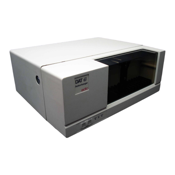
Caution You must ship the DAT Autochanger in the original or equivalent packaging materials or your warranty may be invalidated. Equipment Description The DAT Autochanger The DAT Autochanger is a fully automated, high performance, high capacity, mass storage system designed with a removable data cassette magazine. It is composed of a standard DAT DDS drive and DAT Autochanger-unique hardware (robotics) that are controlled by application software running on your host computer. -
Page 17: Magazine
The heart of the DAT Autochanger is the DAT drive. The DDS (Digital Data Storage) format uses helical scan technology, originally used in digital audio recorders, and adapts it for computer data storage. When equipped with a DDS 3 drive, the DAT Autochanger provides up to 24 GB (at an average 2:1 compression) of removable, highly reliable data storage on a low cost, pocket-sized 125 meter DAT cassette. -
Page 18: Media
Media The DAT Autochanger uses DDS data cassettes. Never use DAT audio grade cassettes, because the media is not certified for data storage. Also, DAT audio grade cassettes have a different mechanical specification, which can cause them to jam in the drive mechanism. -
Page 19: Modes Of Operation
and replace it with the same or equivalent type cassette. See Cleaning the Drive Head, later in this manual. Note After 24 hours of head-tape motion since the last cleaning the LEDs will flash amber in unison. This flashing in unison is the Media Caution signal. -
Page 20: Select Or Confirm Random Access Mode
Select or Confirm Random Access Mode To confirm that the random access mode is selected, check to be sure that the mode selection jumper is installed on the mode selection pins on the back of the control adic module panel (your DAT Autochanger is shipped from with the jumper installed). -
Page 21: Scsi
SCSI SCSI is the acronym for Small Computer System Interface. The interface is a combination of an 8-bit parallel bus (hardware) and a command set (software). SCSI allows you to connect up to seven SCSI devices to any host computer. The SCSI interface is transparent to the host computer. -
Page 22: Confirm And/Or Install The Scsi Host Interface
Note The host computer system normally is the network server. Confirm and/or Install the SCSI host interface The DAT Autochanger must be connected to either an integrated SCSI host or a SCSI interface (host adapter) card installed in the computer – either directly to the SCSI connector on the card or as part of an existing SCSI chain. -
Page 23: Chapter 2 Connecting The Dat Autochanger
Chapter Connecting the DAT Autochanger This Chapter. . . p provides instructions for physically connecting your DAT Autochanger to your host system. -
Page 24: Connecting The Interface Cables
Connecting the Interface Cables First make sure the interface cable you are using has the appropriate connectors on each end. If the host computer's SCSI connector is different from that on the DAT Autochanger, you will need to obtain a different cable than the one supplied with the unit. -
Page 25: Connecting More Than One Dat Autochanger
Note The bail locks at both ends of the SCSI cable must be securely fastened in order for the DAT Autochanger to communicate properly with the computer. p Plug the other end of the SCSI cable into the external SCSI connector on your host computer. -
Page 26: Powering On The System
Note When counting SCSI devices, keep in mind that a DAT Autochanger can contain up to two devices (the DAT drive and the robotics). Don't forget to include in your count other devices on the SCSI channel, (i.e., a tape unit, an additional hard drive, etc.). -
Page 27: Installing The Backup Software
Installing the Backup Software Note This is the software that operates the DAT Autochanger, not the data being transferred to the DAT Autochanger cassettes. Two examples of backup software are Cheyenne's ARCserve and Legato's Networker. Refer to the installation instructions provided with your backup software and install the software on your host computer. - Page 28 Blank Page Connecting the DAT Autochanger...
-
Page 29: Chapter 3 Equipment Description
Chapter Equipment Description This Chapter. . . p explains the switches, indicators and connectors on the front and rear of the DAT Autochanger. p describes the various functions available via the front panel buttons. -
Page 30: Front Panel Switches And Indicators
For the most part, once your DAT Autochanger has been connected to your host computer system and the software has been installed, the DAT Autochanger is ready for use. Just turn on the power switch, place a magazine on the carriage and press the LOAD button on the front panel. - Page 31 Power LED (green) Lights when the power is on. It also reports error conditions (through a blinking sequence). Busy LED (green) Lights whenever the drive is active. It also reports error conditions (through a blinking sequence in conjunction with the Power LED). Note The Power and Busy LEDs are used to indicate that an error has occurred with the DAT Autochanger.
-
Page 32: Rear Panel Switches And Connectors
Rear Panel Switches and Connectors Rear panel switches and connectors are shown in the following illustration. DAT Autochanger Power Switch AC Power Connector CHANGER SCSI ADDRESS DRIVE SCSI connectors Power Switch Turns on the AC power. AC Power Plug the AC power cord into this connector. Connector SCSI Connectors Connections for interface cable that connects DAT... -
Page 33: Chapter 4 Operation And Maintenance
Chapter Operation and Maintenance This Chapter. . . p describes normal operating features of the DAT Autochanger p provides details on the media and magazine p explains normal maintenance procedures... -
Page 34: Inserting The Data Cassettes Into The Magazine
The DAT Autochanger is a highly sophisticated unit composed of a DAT drive and the electro-mechanical robotics that control the drive, magazine, and media. No modifications have been made to the DAT drive. The built-in drive warning lights function as the manufacturer has specified. Very little routine maintenance is required –... -
Page 35: Inserting The Magazine Into The Dat Autochanger
The open side of the magazine faces the DAT Autochanger. Make sure each cassette touches the bottom floor of the magazine. The cassettes will fit firmly in the magazine due to the spring holder (the button-like object on the side of the cassette slot). -
Page 36: Loading The Magazine
p Press down gently while rocking the magazine from side-to-side until it snaps into place. Remove the cover by pressing in on the middle of both ends (where it is labeled PUSH ) and lifting upwards. Loading the Magazine Once you have placed the magazine on the carriage, the DAT Autochanger must initiate a loading process. -
Page 37: Attempting To Load The Magazine With A Cassette Already In Drive
Note In the sequential access mode, if you press UNLOAD before the DAT Autochanger has finished loading the magazine, the robotics will finish mapping and checking the cassettes and then move the magazine to the unload position (the far left) without inserting a cassette into the drive. -
Page 38: Removing The Magazine From The Dat Autochanger
Note The drive eject button is located on the top front of the drive. Look beyond the arm to the drive. p Remove the cassette manually. You can place it back in the magazine, if desired. p Close the DAT Autochanger door. You can now reinitiate the load procedure. Removing the Magazine from the DAT Autochanger If you are using sequential access mode... -
Page 39: If You Are Using Random Access Mode
p Remove the magazine by using two hands to grasp the magazine and pull up and toward you. p Store the magazine in a cool dry place. If you are using random access mode When operated in random access mode, the software usually commands the DAT Autochanger to unload a magazine (or individual cassette). -
Page 40: Removing A Cassette From The Magazine
p Unload the magazine by pressing UNLOAD. The magazine will move completely to the left. p Press LOAD and UNLOAD simultaneously. This will cause the gripper arm to move out from the drive opening. p Open the DAT Autochanger door after the arm is fully extended. p Insert the cassette into the drive opening with the write-protect tab up. -
Page 41: Cleaning The Drive Head
Cleaning the Drive Head Caution Using cloth swabs, cotton swabs, or cleaning agents, will void the warranty. Use only a DDS cleaning cassette. Clean the drive heads and tape path after 8 to 10 hours of tape motion (about once a week under typical use). - Page 42 Caution Use only an approved cleaning cassette to clean the heads. To prevent contamination of the drive and damage to the heads, do not use the cleaning cassette for more than the number of cleaning cycles specified on the cassette label. Discard the cleaning cassette after you have used it the specified number of cleaning cycles.
-
Page 43: Cleaning The Enclosure
Note If there are no more cleaning cycles remaining for the cleaning cassette, the drive will eject it immediately after insertion. p When the cleaning is finished the drive will automatically eject the cassette. Remove the cleaning cassette and write the date on the label so you have a record of how many times it has been used and when. - Page 44 Blank Page Operation and Maintenance...
-
Page 45: Chapter 5 Troubleshooting And Diagnostics
Chapter Troubleshooting and Diagnostics This Chapter. . . p contains some general suggestions to aid you in solving problems – should you ever run into them. p includes information on warning lights. -
Page 46: Dat Autochanger Warning Lights
DAT Autochanger Warning Lights If any component of the DAT Autochanger is not communicating correctly, the POWER LED and the BUSY LED will flash a warning message code. The lights will blink in a sequence indicating a two-digit number. The POWER LED flashes in slow blinks to indicate the left digit, after which the BUSY LED flashes in fast blinks to indicate the right digit. -
Page 47: Error Message Codes
Error Message Codes Meaning/Problem Action Mode of Code Operation Source empty Reset DAT Autochanger and reload magazine. Sequential Cassette present beam Check that cassette present sensor is not Sequential intermittently blocked inadvertently blocked by foreign object. Illegal SCSI ID Change SCSI ID to valid ID using the rear Random panel switch. -
Page 48: Drive Leds
Drive LEDs The drives used in the DAT Autochanger employ front panel LEDs to indicate SCSI interface activity, drive fault conditions, and cartridge status. The following illustration shows a close-up of the Sony SDT5000 drive and the location of the warning lights. - Page 49 Hewlett Packard C1533A/C1537A TAPE LED (bottom) CLEAN LED (top) MEANING Flashing green (½ sec Cartridge activity — load or unload on, ½ sec off) Fast flashing green (¼ sec SCSI activity — read or write on, ¼ sec off) Steady green Cartridge loaded, drive online Flashing amber (½...
- Page 50 Sony SDT-5000/SDT-7000/SDT-9000 Busy LED (Top) Tape LED (Middle) Status LED MEANING (Bottom) No cartridge present/no activity SCSI activity — read or write Fast flashing (¼ sec on, Fast flashing (¼ sec on, Drive loading/unloading ¼ sec off) ¼ sec off) Fast flashing (¼...
-
Page 51: Environmental Considerations
Environmental Considerations For best performance of your DAT Autochanger, please observe the following guidelines: p If you expose cassettes to temperatures outside the operating limits – 40-113°F (5-40°C) – stabilize them by leaving the cassettes in the operating temperature for a minimum of two hours before you use them. p Avoid temperature problems by ensuring that the DAT Autochanger's side and rear are not obstructed, so that the drive has adequate ventilation. - Page 52 p Be prepared to provide: Your name and your Company's name Model number Serial number of unit (located on the rear face by the power switch) Software version numbers device driver archive/restore Hardware configuration, including firmware version, date and number. Type of PC, DOS version, clock speed, RAM, network type, network ver- sion, and any special boards installed Type and brand of media...
-
Page 53: Return For Repair Rma (Return Merchandise Authorization)
Return for Repair RMA (Return Merchandise Authorization) adic When you and Customer Assistance have determined that you need an RMA adic (see section, When You Call Customer Assistance), be prepared with the following information: Note Be sure you have tried all trouble shooting techniques in the various manuals before calling. - Page 54 Blank Page Troubleshooting and Diagnostics...
-
Page 55: Appendix A Glossary
Appendix Glossary This Appendix. . . p contains terms and definitions of expressions commonly used with the DAT Autochanger and the DDS drive. - Page 56 byte 8 bits or one character Celsius (Centigrade) cassette A storage medium item. A cassette is sometimes called a tape or cartridge and is capable of storing vast amounts of magnetically- written data. Some cassettes can store more than 16 gigabytes of data.
- Page 57 load The process where the DAT Autochanger checks each slot to see if a cassette is physically present, and if so, whether the orientation of the cassette in the magazine is correct. It also places the magazine in position for the first cassette to be inserted into the drive. In sequential mode, the first cassette is physically inserted into the drive.
- Page 58 terminator A physical block that tells the SCSI bus that this is the end of the line. A terminator is required at both ends of a SCSI bus. A bus may be terminated internally (on a device inside the host system) or externally on a peripheral device.
-
Page 59: Appendix B Specifications
Appendix Specifications This Appendix. . . p contains specification information on the DAT Autochanger and the DDS drive. -
Page 60: Specifications
Specifications Drive Type: HP C1533A (DDS-2) HP C1537A (DDS-3) Sony SDT-5000 (DDS-2) Sony SDT-7000 (DDS-2) Sony SDT-9000 (DDS-3) Data Transfer Rate: Up to 144 MB/min. (Sony SDT-9000) (average 2:1 compression) Up to 120 MB/min. (HP C1537A) Load Time: 25 seconds max Changer Magazine: 12 Cassettes... - Page 61 Power Consumption Less than 65 Watts Environment Electrical 100-240 VAC Automatic AC line voltage selection Temperature 5° C to 40° C (Operating) -40° C to 70° C (Storage/Shipping) Humidity 20% to 80% (Operating) 5% to 95% (Storage/Shipping) Vibration 0.25G (5-500 Hz) (Operating) 0.5G (5-500 Hz) (Storage/Shipping) Shock 2G Operating...
- Page 62 Blank Page Specifications...
-
Page 63: Index
Index... - Page 64 error messages, 25, 39 — A — AC Power Connector, 20 — F — archiving, 28 front panel, xi, 18, 25, 27, 29, 35, 36 — B — — H — backup software, xi, 2, 7, 9, 15 heads, 5, 6, 22, 29, 30, 44 bail locks, 12, 13 hierarchical storage management, 2, 44 Busy LED, 19, 34, 38...
- Page 65 mode of operation, 3, 7, 14 SCSI device, 13, 14 Mode Selection Jumper, 8 SCSI devices, 9 near-line storage, 2 SCSI host adapter, 3, 10 SCSI ID, x, 9, 14, 20, 35, 45 — N — SCSI ID Selector, 20 SCSI ID switches, 9 necessary tools, 3 SCSI interface, x, 9, 10, 36...
- Page 66 Blank Page Index...
Need help?
Do you have a question about the DAT 160 and is the answer not in the manual?
Questions and answers