ADIC Scalar 24 Installation And Operation Manual
Hide thumbs
Also See for Scalar 24:
- Installation and operation manual (160 pages) ,
- Error code list (4 pages) ,
- Installation and operating manual (84 pages)
Table of Contents
Advertisement
Quick Links
Advertisement
Table of Contents

Related Manuals for ADIC Scalar 24


Summary of Contents for ADIC Scalar 24
- Page 1 Scalar 24 Installation and Operation Guide Document Number: 62-2301-02 Rev A...
- Page 2 ADIC Europe, ZAC des Basses Auges, 1 rue Alfred de Vigny, 78112 Fourqueux, FRANCE. ADIC Europe assumes no responsibility for any errors that may appear in this document, and retains the right to make changes to these specifications and descriptions at any time, without notice.
-
Page 3: Table Of Contents
ADIC Technical Assistance Center ........ - Page 4 ADIC Scalar 24 LTO Tape Driver Installation ....... . 4-9...
- Page 5 Scalar 24 What should I do if I lose power during a backup? ......6-6 How do I get help? .
- Page 6 Scalar 24 Error Messages ........
- Page 7 Scalar 24 Safety and EMC Standards ..........10-3 Power .
- Page 8 Scalar 24 viii 62-2301-02 Rev A...
-
Page 9: Intended Audience
This manual contains information and instructions necessary for the operation of the Scalar library. Intended Audience This guide is intended for general use by anyone interested in learning about or using the Scalar 24. Document Organization The section topics in this guide include: •... -
Page 10: Explanation Of Symbols And Notes
Scalar 24 Explanation of Symbols and Notes The following symbols and highlighted passages note important information: Symbol Damage to ... Signal Word Definition Consequence Person WARNING: Imminent Death or serious injury hazardous electrical situation Material CAUTION: Potential damaging Possible damage to... -
Page 11: Assistance
POWER SUPPLY). MOST IMPORTANTLY, KNOW AND OBSERVE ALL SAFETY RULES BEFORE WORKING WITH THE EQUIPMENT. ADIC Technical Assistance Center If problems cannot be solved with the aid of this document or if training is desired, contact the ADIC Technical Assistance Center (ATAC). In the USA: 800.827.3822... - Page 12 Scalar 24 62-2301-02 Rev A...
-
Page 13: Safety
Heat - Situate the product away from heat sources such as radiators, heat registers, furnaces, or other heat-producing appliances. • Power Sources - Connect the Scalar 24 to a power source only of the type directed in the operating instructions or as marked on the product label. •... -
Page 14: Precautions
The unit is designed for other Scalar 24s to be stacked on top of it (up to three). It is not recommended that you place any other objects on top of the unit. Protective Devices The Scalar 24 is equipped with the following protective devices: • Mechanical Lock •... -
Page 15: Regulatory Notices
Plug the equipment into a different outlet so that the equipment and the receiver are on different branch circuits. • If necessary, consult a representative of ADIC or an experienced radio/television technician for additional suggestions. • Obtain a copy of the following booklet: FCC Interference Handbook, 1996, available from the U.S. -
Page 16: Ic Notice (Canada Only)
Scalar 24 FCC Declaration of Conformity Product Name: Scalar 24 Model Number: SC24 Company Name: Advanced Digital Information Corporation PO Box 97057 Redmond, WA 98073-9757 USA (425) 881-8004 IC Notice (Canada Only) Most tape libraries are classified by the Industry Canada (IC) Interference-Causing Equipment Standard #3 (ICES-003) as Class A digital devices. -
Page 17: Ce Notice
EN 60825-1: 1996 “Safety of Laser Products.” A Declaration of Conformity in accordance with the preceding standards has been made and is on file at ADIC Europe, ZAC de Basses Auges, 1, rue Alfred de Vigny, 78112 Fourqueux, FRANCE. VCCI Notices (Japan Only) This is a Class A product based on the standard of the Voluntary Control Council for Interference for Information Technology Equipment (VCCI). -
Page 18: Declaration Of Conformity
Declaration of Conformity The signed Declaration of Conformity is on file with Advanced Digital Information Corporation, 17275 NE 67th Court, Redmond, Washington 98052, and ADIC Europe, ZAC des Basses Auges 1, rue Alfred de Vigny, 78112 Fourqueux, France. 62-2301-02 Rev A... -
Page 19: Description
With a maximum compressed capacity of 6.72 TB of data storage (for SDLT, including import/export (IE) slot; 4.8 TB for LTO), the Scalar 24 can provide over one month of unattended backup and fits in only 4U (7 inches) of rack space. -
Page 20: Optional Features
An output log, available through the serial port, contains errors, diagnostic messages, and events. 24 Hour Fast Exchange. In the event your Scalar 24 needs to be serviced and you are unable to resolve the problem with the ADIC Technical Assistance Center, ADIC will provide you with a next business day advanced exchange to minimize down time. -
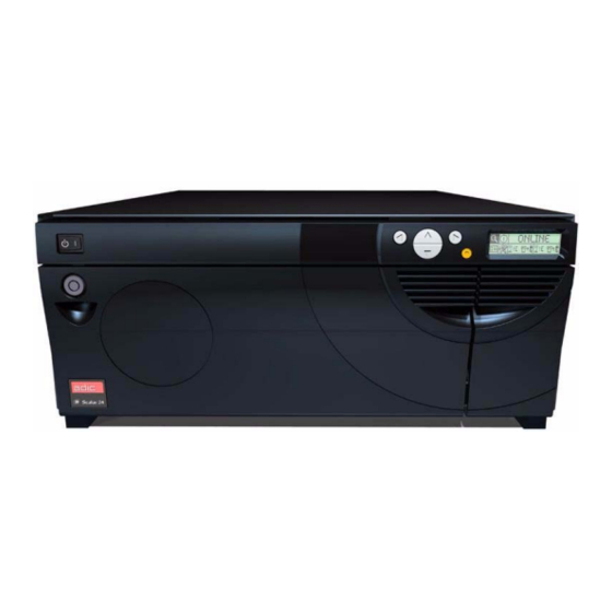
Page 21: Front Panel Components
Scalar 24 Front Panel Components The following graphic shows the components located on the front panel of your Scalar 24. Figure 2 Front View Power Switch Two-position switch that controls power to your Scalar 24. Key Lock Lock that prevents unauthorized media insertion and removal. -
Page 22: Interior Components
Scalar 24 Interior Components The following graphic shows the components located behind the media access and IE doors of your Scalar 24: Figure 3 Interior View Magazines Removable cartridge magazines allow for the easy insertion and removal of tape cartridges. The magazines include transparent windows that enable for easy media viewing. -
Page 23: Rear Panel Components
Scalar 24 Rear Panel Components The following graphic shows the components located on the rear panel of your Scalar 24: Figure 4 Rear View AC Power Connector Receptacle for AC power cord. SCSI Connectors Connections for the interface cable that connect the unit with the host computer and/or other devices on the SCSI channel (including other Scalar 24 units). -
Page 24: Drives
Scalar 24 Drives Your Scalar 24 can be equipped with either one or two drives. The tape drives are packaged in a common drive module that is designed so that you can easily add an additional drive or replace a drive. -
Page 25: Host Interface
Ended (LVD/SE) SCSI bus. Both ends of the bus must be terminated. The Scalar 24 can also be connected to a Fibre Channel Host Storage Area Network (SAN) via the optional Storage Networking Controller (SNC). The SNC converts fiber channel protocol to parallel SCSI protocol. - Page 26 Scalar 24 62-2301-02 Rev A...
-
Page 27: Getting Started
Scalar 24, below the right magazine. (You will need to remove the magazine to view the label.) Checking the Accessories Check to make certain that the following items are included with your Scalar 24 and that none of them are damaged: •... -
Page 28: Installing Hardware
The Scalar 24 uses a 68-pin LVD SCSI connector on the rear panel. • If your host computer’s SCSI connector is different from the one on the Scalar 24, you will need to obtain an adapter or a different cable. Consult your dealer or ATAC if you need help. - Page 29 Connecting More than One Scalar 24 If you are connecting more than one Scalar 24 on the same SCSI channel, connect each unit to the previous unit with an additional shielded interface cable. It does not matter which SCSI connector on each Scalar 24 you connect the interface cable to.
-
Page 30: Connecting The Power Cord
Step 2 Plug the power cord into the AC receptacle on the rear panel of your Scalar 24. WARNING: USE CAUTION WHEN PLUGGING THE POWER CORD INTO AN ELECTRICAL OUTLET. HAZARDOUS VOLTAGES ARE PRESENT IN THE SOCKETS OF THE OUTLET. -
Page 31: Inserting Tape Cartridges
Scalar 24 Figure 4 Connecting the power cord CAUTION: Ensure that the AC line cord from the library is plugged directly into the socket. Extension cords should not be used. Inserting Tape Cartridges Make sure that the write-protect switch is set appropriately on each cartridge. Slide the switch to the appropriate position by pushing it with your finger. - Page 32 Inserting and Removing Media on page 7-4. Step 4 Re-install the magazines into the Scalar 24. NOTE: You will need to push firmly to fully insert the magazines. Step 5 Close the media access door. Refer to...
-
Page 33: Setting Up Your Scalar 24
Setting up your Scalar 24 After you have set up your host computer, you need to configure your library. Your Scalar 24 provides you with the unique ability to set up the library using a Setup Wizard. The Setup Wizard guides you step-by-step through the setup process ensuring that all elements are configured in the proper order. -
Page 34: Preparing The Host Computer
8-3. Preparing the Host Computer All device drivers for your Scalar 24 are located on the CD included with the library and are also available on the ADIC support website. At this point, you need to refer to your software installation guide for instructions on installing the backup/controlling software for the Scalar 24 onto the host computer. -
Page 35: Adic Scalar 24 Lto Tape Driver Installation
Scalar 24 Step 14 Make sure that in Device Manager, under Medium changers, ADIC Scalar 24 Tape Library is listed. ADIC Scalar 24 LTO Tape Driver Installation Windows 2000 Driver File Installation Step 1 Start the Windows 2000 Device Manager. -
Page 36: Adic Scalar 24 Sdlt Tape Driver Installation
Required files will be installed for the driver now. Step 10 Click Finish. Step 11 Click Close on the Properties page. Step 12 In Device Manager, make sure that the ADIC Scalar 110T SDLT 320 is listed under Tape Devices. 4-10... - Page 37 Scalar 24 Windows NT 4.0 Driver File Installation Step 1 Click the Start button, point to Settings, then click Control Panel. Step 2 Double-click the Tape Devices icon. NOTE: If the host server or workstation already has drivers installed, continue with the next step, otherwise, skip the next two steps.
- Page 38 Scalar 24 4-12 62-2301-02 Rev A...
-
Page 39: Installing Optional Hardware
Storage Networking Controller Installing an Additional Drive Your Scalar 24 comes with either one or two drives. If you have one drive, you can install an additional drive by following the procedure below. Your Scalar 24 can contain up to two drives. -
Page 40: Installing The Remote Management Unit
8-21. Installing the Remote Management Unit The Remote Management Unit (RMU) allows you to access your Scalar 24 via a web browser. Follow the procedure below to install the RMU. Step 1 Remove the RMU from the packaging. - Page 41 Plug the power cord into a grounded electrical socket. Step 6 Power on the Scalar 24. The library will detect the presence of the RMU. You will need to set the IP Address, Subnet Mask, and Gateway Address before the RMU will function. You can do this through the...
-
Page 42: Installing The Scalar 24 In A Rack
Your Scalar 24 can easily be converted to a rackmount configuration. Follow the steps below to install your Scalar 24 into a rack. Special care should be taken when installing a Scalar 24 into a rack. Heed the following guidelines: •... - Page 43 Scalar 24 Figure 5 Cosmetic cover removal Step 6 Using a #1 Philips screwdriver, remove the cosmetic feet by removing the two screws on each foot. Figure 6 Foot removal Step 7 Using a #1 Philips screwdriver, remove the interior front support plate by removing the four screws on the plate.
- Page 44 Figure 7 Interior front support plate removal Step 8 Using a #1 Philips screwdriver, attach the two securing brackets to the front sides of the Scalar 24 using one screw for each bracket as shown below. Figure 8 Attaching securing brackets Step 9 Locate the mounting holes on the rack where you want to install the library.
- Page 45 Scalar 24 Step 10 Using a #3 Philips screwdriver, attach the side rails to the front of the rack using two screws per rail (four total). You may need to use a caged nut to secure the rail to the rack.
- Page 46 Figure 11 Fully assembled rackmount hardware Step 12 Slide the Scalar 24 onto the rackmount hardware until it stops. Step 13 Attach the securing brackets on the front Scalar 24 to both sides of the rack by tightening the thumbscrews on the securing brackets.
-
Page 47: Installing The Storage Networking Controller
Remove the SNC from the packaging. Step 2 Power down your Scalar 24 and disconnect the AC line cord from the AC source outlet. Step 3 From the rear of the Scalar 24, locate the available SNC slot. Loosen the four thumbscrews on the cover plate and remove the cover plate. - Page 48 Scalar 24 Figure 13 SNC cover plate removal Step 4 Slide the SNC into position and until it mates with the connector then tighten the thumbscrews. 5-10 62-2301-02 Rev A...
- Page 49 Scalar 24 Figure 14 SNC installation Step 5 Plug the power cord into a grounded electrical socket. NOTE: For complete instructions on installing and configuring your SNC, please refer to the SNC 4000 User’s Guide. Installing Options 5-11...
- Page 50 Scalar 24 5-12 62-2301-02 Rev A...
-
Page 51: Frequently Asked Questions
8-3 for step-by-step instructions and descriptions of each submenu. How do I set a SCSI ID? Your Scalar 24 has two types of SCSI IDs. There is one for the library and a separate SCSI ID for each drive. Refer to Set SCSI IDs on page 8-21. -
Page 52: What Type Of Terminator Is Required
Connecting to a SCSI Bus on page 4-2. Where are the drivers located? Drivers for your Scalar 24 can be found on the CD-ROM in the drivers directory. For the latest drivers, check the Scalar 24 website at www.adic.com/scalar 24. If you need assistance installing the drivers, please contact ATAC. -
Page 53: How Do I Upgrade Firmware
AMC User’s Guide. How do I clean a drive? There are three ways to clean a drive on your Scalar 24: manually, using autoclean, and host controlled. • For information about manually cleaning the drive, see Clean Drive on page 8-65. -
Page 54: What Is The Life Span Of The Cleaning Tape
What is the life span of the cleaning tape? Your Scalar 24 came with a cleaning tape. This tape should be used to clean the drive(s) of your Scalar 24 when the icon appears in the drive status field of the LCD. -
Page 55: What Is Partitioning
Use the serial number when contacting ATAC for assistance. What is partitioning? Partitioning is the way to allow your single Scalar 24 library to be logically partitioned so it will appear to a host as if it were two independent physical libraries. Each logical library (partition) can be independently controlled as though it were two different libraries. -
Page 56: What Format Should I Use For My Barcodes
You may need to clear the tape manually. Manual Removal of Tapes on page 9-5 for more information. How do I get help? ADIC has a Technical Assistance Center known as ATAC. You can reach ATAC using the following methods: In the USA: 800.827.3822 Outside the USA, toll free: 00.800.9999.3822... -
Page 57: Operator Panel Keypad
Action button Execute Menu Option Icon Definitions The LCD on the Scalar 24 uses icons to provide graphical representations of menu items. From the Main menu, you can view menu icons as well as drive and tape status icons. Library status... -
Page 58: Menu Icons
Scalar 24 Menu Icons A list of the menu icons and their descriptions are provided in the table below. Icon Description Icon Description STATUS Menu SETUP Menu Display Firmware Version Setup Wizard Display Inventory Configure Slots Display Motion Counts Set SCSI IDs... -
Page 59: Drive Status Icons
Scalar 24 Drive Status Icons The following shows the icons that are displayed on the LCD indicating drive status. Power On Write Protect Compression On Cleaning Required Tape Activity, Drive Error, or Drive Presence Figure 2 Drive Status Icons Icon... -
Page 60: Tape Activity Icons
All status information is available in offline mode. Inserting and Removing Media Your Scalar 24 has been designed to make media insertion a simple and accurate process. There are three ways to insert and remove media from the Scalar 24:... -
Page 61: Barcode Labels
A barcode must use only uppercase letters A to Z and/or numeric values 0 to 9. The Scalar 24 currently supports Code 39 type barcode labels. Three different types of barcode label modes are supported in the Scalar 24: Default: The scanner will expect to read and report to the host six characters. -
Page 62: Applying The Label
Scalar 24 The barcode scanner will read and report the information that it scans and will display this information on the Operator Panel. The library will report the barcode information to the host according to the mode it is configured for and will display alert messages on the Operator Panel LCD if the scanned barcode does not match the barcode length and media identifier requirements of the mode. -
Page 63: Submenu Navigation
Scalar 24 Use left and right arrow keys to move between these 4 icons Submenu Navigation There are two levels of submenu navigation. The first level allows you to move between the various submenu items. This type of tabbing works the same as the Main menu tabbing, using the left and... -
Page 64: Normal Operations
Scalar 24 Normal Operations Once your Scalar 24 and your choice of application software are installed and configured, you can automatically perform backup and restore operations through the application software. You do not need to intervene unless you need to replace cartridges. -
Page 65: System Administrator Responsibilities
Scalar 24 System Administrator Responsibilities The System Administrator (SA) must set up the RMU for proper operation. The SA responsibilities include establishing a network address for the RMU and establishing the Uniform Resource Locators (URL). The network address consists of an Internet Protocol (IP) address, subnet mask, and gateway IP Address. - Page 66 Scalar 24 • URL identifier and equipment type Refer to Top Information Frame on page 7-14 for the dialog. The third segment is the center navigation frame. The center navigation frame has six tab-style hyperlinks as indicated in the following list: •...
- Page 67 This hyperlink opens a new page and displays a brief description of the Status, Configuration, Firmware, Diagnostic files, Operator Panel, and Logs tabs. Documentation This hyperlink opens a new page for the ADIC website, redirects the user, and displays the library documentation file hyperlink. SNMP MIB This hyperlink opens a new page and displays an explanation of the SNMP MIB.
- Page 68 Both information from the library (command and error logs) and information from the RMU (error log) can be retrieved in text form. The system snapshot is a machine decodable file which can only be used by ADIC service personnel. •...
- Page 69 Figure 7 Technical Support Dialog Example Hyperlink Description ADIC Technical Assistance Center This hyperlink opens an email dialog to ADIC technical support center for North America (support@adic.com). support@adic.fr This hyperlink opens an email dialog to ADIC technical support center for the remainder of the world.
- Page 70 Scalar 24 Figure 8 Version Dialog Example Top Information Frame The Top Information Frame dialog and description are indicated below. Figure 9 Top Information Frame Hyperlink Description Name This location indicates the URL identifier of the RMU site and the attached library type.
- Page 71 This field value indicates the library serial number. The physical serial number, which appears on the product safety label, is embedded in this number. This number also includes the vendor ID (ADIC in the example above) and the partition (0 in the example above).
- Page 72 If either user name or user password are not verified, the login is rejected. NOTE: After the Admin user has initially logged into the RMU, ADIC recommends that the Admin user change the default password. The Configuration dialogs and descriptions are indicated below. All values shown are for example only.
- Page 73 Scalar 24 Figure 12 Configuration Dialog Example Hyperlink Description Configuration The Configuration tab displays the current configuration status of the RMU and user account. The fields and values that are associated with this tab are indicated below. Hostname This field value indicates the Hostname used for the RMU configuration.
- Page 74 Scalar 24 This selection enables SNMP feature. Alerts Enabled This pull down menu allows the user to enable or disable SNMP server alerts. This selection disables SNMP server alerts. This selection enables SNMP server alerts. Manager This field value indicates the SNMP server address.
- Page 75 Scalar 24 TimeZone This field value indicates the time zone deviation for the NTP server. Click on the link to see the list of time zones (Figure 13). You will need to enter the value from this list that corresponds to your time zone.
- Page 76 Scalar 24 Figure 14 Confirm Configuration Changes Dialog Example Hyperlink Description Password The user must enter their password. Confirm This button confirms the configuration changes. The Firmware dialog and descriptions are indicated below. 7-20 62-2301-02 Rev A...
- Page 77 Scalar 24 Figure 15 Firmware Dialog Example Hyperlink Description Firmware The Firmware tab updates the firmware version of the RMU or the library. The fields and values that are associated with this tab are indicated below Select target for update This section allows the user to select which firmware is to be upgraded.
- Page 78 Scalar 24 Figure 16 Firmware Download Times The Diagnostic file dialog and descriptions are indicated below. Figure 17 Diagnostics File Dialog Example 7-22 62-2301-02 Rev A...
- Page 79 Scalar 24 Hyperlink Description Diagnostic file The Diagnostic file tab displays the library command error log, library error log, or RMU error log. The fields associated with this tab are indicated below: Select the file to This selection allows the user to choose which log to retrieve.
- Page 80 Scalar 24 Figure 19 Logs Dialog Example Hyperlink Description Logs The Logs tab displays the library logs. 7-24 62-2301-02 Rev A...
-
Page 81: Using The Menus
Scalar 24 Using the Menus The Operator Panel provides a menu-driven operator interface to the Scalar 24. The menus allow you to view and set the operating parameters of the Scalar 24. Menu Tree Structure Each menu is accessible through the Operator Panel keypad. Refer to Operator Panel Keypad page 7-1 for an illustration and definition of the keypad. -
Page 82: Main Menu
Scalar 24 Main Menu The Main menu is the initial screen that allows you to access to the Status, Command, Setup, and Tools menus. Command Menu Status Menu icon Library status icon Setup Menu icon Tools Menu Drive status icon... -
Page 83: Setup Menu
Scalar 24 Menu Description Setup Menu on page 8-3 provides selections to: • Setup Wizard on page 8-4 • Configure Slots on page 8-14 • Set SCSI IDs on page 8-21 • User Interface on page 8-25 • Configure RMU on page 8-28 •... -
Page 84: Setup Wizard
Scalar 24 Figure 2 Setup Menu Setup Wizard Setup Wizard walks you through the process of configuring your library. Using the wizard, you can configure all of the desired settings from one location in the menu instead of going to each individual item in the menu. - Page 85 Scalar 24 Selection Description/Result Step 2 You will be prompted to cancel the Setup Wizard. Press to select Do Not Show. Step 3 Press to highlight Execute ( The Setup Wizard closes and will not be and then press shown again at power up. To access the Setup Wizard, go to the Setup menu.
- Page 86 Scalar 24 Selection Description/Result insert graphic Step 4 Press and then to accept the changes and move to the next option. Available options are: • on: library is split into two partitions. The host will be affected (reduced slot/drive count) based on which partition it is attached •...
- Page 87 Scalar 24 Selection Description/Result Available options are: • Both: Cleans both partitions • Part 1: Only cleans Partition 1 • Part 2: Only cleans Partition 2 Step 8 Press to select the mode for Autoclean. Step 9 Press and then to accept the changes and move to the next option.
- Page 88 Scalar 24 Selection Description/Result The slots in the magazine on the left are always Partition 1 and the slots in the magazine on the right are always Partition 2. You can designate a minimum of 8 slots for Step 12 If you enabled partitioning, press...
- Page 89 Scalar 24 Selection Description/Result Available options are: • Sequential: Requires the backup software to write the data to each of the tape cartridges sequentially, starting with the first one. Step 16 Press to select the mode for Partition 2. Step 17 Press...
- Page 90 Scalar 24 Selection Description/Result Sets the inquiry string returned to the host in a SCSI inquiry command. Available options are: • Scalar 24 • Scalar 100 Step 24 Press to set the Inquiry mode. • Scalar 1000 • Scalar 10K...
- Page 91 Scalar 24 Selection Description/Result The current field will be highlighted. You must select a numeric value between 0 and 9 for all four fields. Step 30 If you enabled a password, set the password by pressing change the value of the current field to move between fields.
- Page 92 Scalar 24 Selection Description/Result Available options are: • Default: The scanner will expect to read and will report to the host six characters. Optional one or two character media identifiers can be present but will not be reported. Step 36 Press to select the •...
- Page 93 Scalar 24 Selection Description/Result The current field will be highlighted. Make sure you enter a valid number for each field. Step 40 Set the Gateway by pressing to change the value of the current field and to move between fields.
-
Page 94: Configure Slots
Scalar 24 Configure Slots Configure Slots allows you to set up specific slots of your library to be allocated for various functions, such as cleaning and partitioning. Path: Main Menu Setup Menu Configure Slots Configure Cleaning Slots This option allows you to designate specific rear slots to be used as cleaning slots. If you wish to enable Autocleaning, you must configure at least one cleaning slot. - Page 95 Scalar 24 Selection Description/Result You can allocate up to four slots to be used for cleaning. Slots 20 - 23 can be used as cleaning slots for LTO or slots 17 - 20 for SDLT. When a slot is configured for cleaning, a C appears in that...
- Page 96 Scalar 24 Configure Modes This option allows you to set up your library to run in Random or Sequential mode. Random This mode is used when you are connected to host application software that recognizes a library media changer device. It allows your host...
- Page 97 Scalar 24 Selection Description/Result There are four mode settings: • Rnd: sets the library to Random mode • Seq: sets the library to Sequential mode • Rnd-Seq: sets Partition 1 to Random mode and Partition 2 to Sequential mode. By...
- Page 98 Scalar 24 Configure Partitions Partitioning is used to allow your single Scalar 24 library to be logically partitioned so it will appear to a host as if it were two independent physical libraries. Each logical library (partition) can be independently controlled as though it were two different libraries. The partitioning types available are random-sequential and sequential-sequential;...
- Page 99 Scalar 24 Selection Description/Result The slots in the magazine on the left are always Partition 1 and the slots in the magazine on the right are always Partition 2. You can designate a minimum of 8 slots for Step 4...
- Page 100 Scalar 24 Selection Description/Result The library is configured for the specified partitions. Step 5 Press to highlight Execute ( and then press Step 6 A confirmation screen displays. Press to dismiss. Configure IE Slot This option allows you to configure the IE slot as either a storage slot or an Import/Export slot. If it is configured as a storage slot, it will show up as a valid storage slot to the host application.
-
Page 101: Set Scsi Ids
Scalar 24 Selection Description/Result The IE slot is configured. Step 5 Press to highlight Execute ( and then press Step 6 A confirmation screen displays. Press to dismiss. Set SCSI IDs SCSI allows you to set the SCSI ID for the library and drives. The SCSI ID identifies which ID the library and drives respond to when communicating with the host. - Page 102 Scalar 24 Selection Description/Result Sets the library SCSI ID. You must have at least one partition set to Random mode to use this option. See Configure Modes on page 8- 16 for more information. Step 2 Highlight and press You must choose a number between 0 and 7.
- Page 103 Scalar 24 Selection Description/Result Sets the drive SCSI IDs. Step 2 Highlight and press You must choose a number between 0 and 15. The default ID is 1. Step 3 Press to select the ID you would like to set for the Drive 1.
- Page 104 Scalar 24 Set Inquiry Set Inquiry allows the host to see your library as another existing ADIC Scalar product. This can be useful if the host software does not currently include drivers to communicate with the Scalar 24. Selection Description/Result Sets SCSI IDs.
-
Page 105: User Interface
Scalar 24 User Interface User Interface allows you to configure the LCD timeout, password, and key click settings. Path: Main Menu Setup Menu User Interface Set Timeout Timeout selects how long the library is available for operator menu selections before it automatically returns to the Main menu due to screen inactivity. - Page 106 Password allows you to enable or disable a password for access to the library. This enables you to prevent unauthorized personnel from disrupting the operation of the Scalar 24. If a password is set, it will be required to view or execute any of the options in the Setup, Command, or Tools menus.
- Page 107 Scalar 24 Selection Description/Result Available options are: • on: password will be required to access secure menu features • off: disabled Step 2 Press to Enable/Disable NOTE: If the password is enabled via the the password function. SCSI host, you cannot modify or disable the password using the LCD display.
-
Page 108: Configure Rmu
Scalar 24 Set Key Clicks Key Click allows you to enable or disable an audible tone when the keys on the keypad are pressed. Selection Description/Result Step 1 From the Setup menu, highlight and press Sets key clicks. Step 2... - Page 109 Scalar 24 The optional Remote Management Unit (RMU) provides remote host operation through a web browser. Once you have installed the RMU, you configure it using this menu option. For more information on installing/replacing the RMU, see Installing the Remote Management Unit page 5-2.
-
Page 110: Configure Autoclean
For more information on configuring cleaning slots, see Configure Cleaning Slots on page 8-14. The Scalar 24 will track the usage of the cleaning tape and post an alert message on the LCD once the cleaning tape has expired and requires you to export the tape. - Page 111 Scalar 24 Path: Main Menu Setup Menu Autoclean Autoclean Unpartitioned Library Selection Description/Result Configures automatic cleaning of drives. Step 1 From the Setup Menu, highlight and press Available options are: • on: the library will automatically clean the drives when cleaning is required. Overall slots available for data cartridges will be reduced.
-
Page 112: Configure Barcode Scanner
Scalar 24 Autoclean Partitioned Library Selection Description/Result Configures automatic cleaning of drives. Step 1 From the Setup Menu, highlight and press Available options are: • P1 on P2 on: autoclean is enabled for both partitions • P1 on P2 off: autoclean is enabled for... - Page 113 Scalar 24 Path: Main Menu Setup Menu Scanner Selection Description/Result Configures the barcode scanner. Step 1 From the Setup menu, highlight and press Available options are: • on: all media will be scanned for barcodes. Unlabeled or unreadable labeled media will generate a user message.
-
Page 114: Reset Configuration
Press to dismiss. Reset Configuration Reset Config allows you to reset your library to the default settings. For more information of the default values, see Setting up your Scalar 24 on page 4-7. Path: Main Menu Setup Menu Reset Config... -
Page 115: Command Menu
A warning screen will prompt you to ensure that you want to reset the library configuration. Press continue. Command Menu The Command Menu provides access to commands that cause motion within the Scalar 24. From the Command menu, you can: • Import media •... -
Page 116: Import Media
Scalar 24 Import Media Import allows you to move a data or cleaning tape cartridge from the IE slot to other location in your library. This allows you to insert a tape into the library without opening the front door. If your IE slot is configured as a storage slot, you will need to remove any present data cartridge before running this command. - Page 117 Scalar 24 Selection Description/Result The data cartridge is imported to the first available slot starting with Slot 1. Step 4 A confirmation screen displays. Press to dismiss. Import Data Cartridge for Partitioned Library Selection Description/Result Step 1 Open the IE door and insert a data cartridge into the IE Slot.
- Page 118 Scalar 24 Selection Description/Result Step 6 A confirmation screen displays. Press to dismiss. Import Cleaning Cartridge Selection Description/Result Step 1 Open the IE door and insert a cleaning cartridge into the IE Slot. Imports media from IE slot. Step 2...
-
Page 119: Export Media
Scalar 24 Selection Description/Result You will need to specific how many times this cartridge has been used, if any. Step 6 Press to select the how many times the cleaning tape has been used. Step 7 Press to move to next field. - Page 120 Scalar 24 Path: Main Menu Command Menu Export Export Data Cartridge Selection Description/Result Step 1 Open the IE door and check the IE slot to make sure that it is empty. If a tape is present, remove it. Exports media to IE slot.
- Page 121 Scalar 24 Selection Description/Result Step 6 A confirmation screen displays. Press to dismiss. Step 7 You can continue to export data cartridges, or you can exit to the Command menu. Press twice to highlight and then press return to the Command menu.
-
Page 122: Dismount Drive
Scalar 24 Selection Description/Result The specified cleaning cartridge is exported to the IE slot. Step 5 Press to highlight Execute ( and then press Step 6 A confirmation screen displays. Press to dismiss. Step 7 You can continue to export cleaning cartridges, or you can exit to the Command menu. -
Page 123: Move Media
Scalar 24 Selection Description/Result Moves media within your library. Step 1 From the Command menu, highlight and press Step 2 The cartridges are unloaded from the drives and returned to their source slots. Step 3 A confirmation screen displays. Press to dismiss. - Page 124 Scalar 24 Selection Description/Result Moves media within your library. Step 1 From the Command menu, highlight and press SRC = Source Slot TGT = Target Slot The move media screen provides a visual representation of the storage slots in your library.
- Page 125 Scalar 24 Selection Description/Result Step 3 Press to move the cursor to the target field. In this example, the cartridge in the source slot 15 is moved to the target slot IE. Step 4 Press to select the target slot.
-
Page 126: Bulk Load
Scalar 24 Step 7 You can continue to move media, or you can exit to the Command menu. Press twice to return to the Command menu. Bulk Load Bulk Load allows you to move multiple tapes from the magazines to the rear slots with one command. - Page 127 Scalar 24 Partitioned Library Bulk Load Selection Description/Result Moves cartridges from magazines to partitioned rear slots. Step 1 From the Command menu, highlight and press Available options are: • Partition 1: will move cartridges from the left magazine to the available rear Partition 1 slots.
-
Page 128: Bulk Unload
Scalar 24 Selection Description/Result Step 5 When the bulk load is complete, a completion screen is displayed. Press to dismiss the screen. Bulk Unload Bulk Unload allows you to move all of the tapes from the rear slots to the front magazines with one command. - Page 129 Scalar 24 Partitioned Library Bulk Unload Selection Description/Result Moves cartridges from rear slots to magazines. Step 1 From the Command menu, highlight and press Available options are: • Partition 1: will move cartridges from the rear Partition 1 slots to the left magazine slots.
-
Page 130: Sequential
Sequential Start Loop Start Loop mode allows you to operate in a continuous backup mode. When all tape cartridges have been filled with data, the Scalar 24 will begin again with the first cartridge, overwriting tape cartridges upon reuse. 8-50... - Page 131 Scalar 24 Selection Description/Result Sets options for sequential backup. Step 1 From the Command menu, highlight and press Starts looped sequential backup. Step 2 Highlight and press Step 3 Press to select the partition you want to set to sequential loop mode.
- Page 132 Scalar 24 Selection Description/Result Sets options for sequential backup. Step 1 From the Command menu, highlight and press Starts single sequential backup. Step 2 Highlight and press Step 3 Press to select the partition you want to set to sequential single mode.
- Page 133 Scalar 24 Selection Description/Result Sets options for sequential backup. Step 1 From the Command menu, highlight and press Stops sequential backup. Step 2 Highlight and press Step 3 Press to select the partition you want to stop the sequential backup on.
-
Page 134: Status Menu
Scalar 24 Selection Description/Result Sets options for sequential backup. Step 1 From the Command menu, highlight and press Continues sequential backup. Step 2 Highlight and press Step 3 Press to select the partition you want to resume the sequential backup on. -
Page 135: Display Firmware Version
Display Firmware displays the current level of firmware you are running. This information is important for troubleshooting problems.You can also compare the version numbers with the latest available versions on the ADIC website (www.adic.com) to determine if a newer version is available. -
Page 136: Display Inventory Information
Display Inventory Information Inventory provides a display of the tape cartridges present in the rear slots and magazines. A physical inventory is also conducted each time you power on your Scalar 24. Path: Main Menu Status Menu... - Page 137 Scalar 24 Selection Description/Result The inventory screen provides a visual representation of the storage slots in your library. • Magazine slots: • shown on the bottom of the screen • numbered sequentially from left to right Step 2 Press to scroll through 01 to 14 for LTO or 01 to 12 for SDLT the various slots.
-
Page 138: Display Motion Counts
Scalar 24 cleaning Rear slots tape in slot (empty) Drives 15 - 23 drive Picker Magazine IE slot partition slots 1 - 14 tape in slot is tape in divider slot selected IE slot barcode scanner results Selection Description/Result You are returned to the Status menu. -
Page 139: Display Retry Counts
Scalar 24 Selection Description/Result Displays slot usage information. Step 1 From the Status menu, highlight and press You can view motion counts for: • System Moves: displays the total number of library moves. A move is described as a "get" from one location and a "put" to another location. - Page 140 Scalar 24 Path: Main Menu Status Menu Retry Counts Selection Description/Result Displays the number of retry operations. Step 1 From the Status menu, highlight and press You can get retry counts on the number of: • System: displays the total number of library retries.
-
Page 141: Display Sensor Status
Scalar 24 Display Sensor Status Sensor Status displays the results of the real-time sensors on your Scalar 24. Path: Main Menu Status Menu Sensor Status Selection Description/Result Displays results of real-time sensors. Step 1 From the Status menu, highlight and press You can view sensor status for: •... -
Page 142: Display Errors
100 errors and is preserved through power cycles. The log is accessible via the LCD as well as the SCSI interface, the serial port, and the RMU interface. You may be asked to supply log information to ADIC technical support for troubleshooting purposes if other problem resolution strategies do not work. -
Page 143: Display Serial Number
Scalar 24 Selection Description/Result Step 4 Press to dismiss the message and return to the Error log. You are returned to the Status menu. Step 5 To exit the Error log, press highlight and then press Display Serial Number Serial Number displays the serial numbers of the library, drives, and the RMU. You may need this information when contacting Technical Support. -
Page 144: Tools Menu
You are returned to the Status menu. Step 3 To exit, press to highlight then press Tools Menu The Tools Menu provides access to Scalar 24 utilities. From the Tools Menu you can: • Manually clean a drive • Load firmware •... -
Page 145: Clean Drive
Scalar 24 Clean Drive Clean Drive allows you to manually clean your drive components. To use this feature, you must have at least one slot configured as a cleaning slot, and it must contain a cleaning cartridge. For more information on configuring cleaning slots, see Configure Cleaning Slots on page 8-14. -
Page 146: Load Firmware
Scalar 24 Load Firmware Load Firmware allows you to manually update your firmware using a firmware upgrade tape cartridge. Path: Main Menu Tools Menu Load Firmware Selection Description/Result Step 1 Open the IE door and inset the firmware upgrade tape into the IE slot. -
Page 147: Demo Test
Scalar 24 Selection Description/Result Step 5 A confirmation message is displayed. Press to dismiss. Step 6 Remove the upgrade tape from the IE slot. Demo Test Demo Test randomly moves tapes within the library to demonstrate robotic motion. Path: Main Menu... -
Page 148: Self Test
Scalar 24 Selection Description/Result Step 4 Press to move to the next option. You can select between 1 and 100 cycles. Step 5 Press to select the number of Cycles to include in the demo test. The demo test begins. -
Page 149: Drive Maintenance Test
Scalar 24 Selection Description/Result Runs self test. Step 1 From the Tools menu, highlight and press The self test begins. Step 2 A status screen will display the progress of the test. You can press at any time to cancel the test. - Page 150 Scalar 24 Normal Read/ The drive reads and writes 96 wraps worth of data (all the tracks) in each of Write the four data sections. No more than 1.5% of the tape is used. Ten data patterns are used in this test. This test takes approximately 3 minutes.
-
Page 151: Manufacturing Test
Scalar 24 Selection Description/Result Step 3 Press to select the drive you wish to run the test on. Step 4 Press to move to the next option. Available options are: • POST • Fast R/W • Normal R/W • Media R/W... - Page 152 Scalar 24 Selection Description/Result Runs Manufacturing test. Step 1 From the Tools menu, highlight and press CAUTION: This test will move your tapes and may change your inventory information by not placing tapes in the same locations. Step 2 You will be prompted with a warning, press to continue the test.
-
Page 153: Position Picker
Scalar 24 Selection Description/Result The Manufacturing test begins. Step 8 Press to highlight Execute ( and then press Step 9 A status screen will display the progress of the test. You can press at any time to cancel the test. -
Page 154: Output Logs
Scalar 24 Selection Description/Result Step 1 From the Tools menu, highlight and press TGT = Target slot to position the picker in front Step 2 Press to select the target slot to move the picker to. The picker moves to the specified position. -
Page 155: Replace A Drive
Scalar 24 Path: Main Menu Tools Menu Output Logs Selection Description/Result Outputs logs. Step 1 From the Tools menu, highlight and press Step 2 When the output is complete, a completion message is displayed. Press to dismiss. Replace a Drive Replace Drive either prepares a drive to be removed or reactivates a drive once it is installed. - Page 156 Scalar 24 Selection Description/Result Prepares a drive to be removed/replaced. Step 1 From the Tools menu, highlight and press Step 2 Press to select the drive you wish to remove. The drive is ready to be removed. Step 3 Press to highlight Execute (...
- Page 157 Scalar 24 Selection Description/Result Step 2 Press to select the drive you wish to remove/replace. The new drive can be used. Step 3 Press to highlight Execute ( ) and then press Using the Menus 8-77...
- Page 158 Scalar 24 8-78 62-2301-02 Rev A...
-
Page 159: Troubleshooting And Diagnostics
This chapter contains some general suggestions to aid you in solving problems. Installation Problems Usually, problems encountered during the installation of your Scalar 24 are caused by improper SCSI bus configuration application software configuration errors or by an OS that has not been correctly configured. -
Page 160: Scalar 24 Error Messages
Scalar 24 Scalar 24 Error Messages If an error occurs during the operation of your Scalar 24, an error message will be displayed on the operator’s display. The following table lists the error messages you may encounter and recommend actions. - Page 161 Scalar 24 Error Message Description Recommended Action Code Barcode Error The scanned barcode is Check barcode scanner Check Tape incorrect for your current configuration. See Configure configuration. This is most Barcode Scanner on page 8- likely the result of a missing 32 for more information.
- Page 162 Scalar 24 Error Message Description Recommended Action Code Drive Error Communication to a drive is Reboot the system. If the Check Drive not working, the drive is not problem persists, remove the initializing, or the drive is drive and re-install it. If the reporting a problem.
-
Page 163: Manual Removal Of Tapes
Scalar 24 Error Message Description Recommended Action Code Security Alert The system has detected Check and ensure that Check Door operator interference, such as magazines are installed, the an open door and magazine door is closed, and that the IE removal, or a host has issued slot is empty. -
Page 164: Manual Removal Of A Tape From A Drive
Step 3 Open the front door and remove the two magazines. Step 4 Reach into the back of the Scalar 24 and press up on the green lever to release a tape from the rear slot. Step 5 Gently pull the tape out toward you. -
Page 165: Environmental Considerations
For best performance of your Scalar 24, and to minimize the chance of condensation, please observe the following guidelines: • Install your Scalar 24 on a level surface. Do not place the Scalar 24 on a carpeted surface. • If you expose cartridges to temperatures outside the operating limits, (see Specifications), stabilize them by leaving the cartridges in the operating temperature for a minimum of two hours before you use them. - Page 166 Your name and your company’s name • Model number • Serial number of the Scalar 24 (obtained from the operator panel or located inside the unit, under the right magazine) • Serial number of drive assembly (located on rear panel, above SCSI connectors) •...
-
Page 167: Specifications
Scalar 24 Specifications The following tables provide specification information about the Scalar 24. Dimensions NOTE: Above measurements in inches. Weight Library with 1 drive 55 lbs (25 kg) Library with 2 drives 54 lbs (24.5 kg) Rackmount Library 43 lbs (19.5 kg) -
Page 168: Storage Slot Count
Scalar 24 Rackmount Library 42 lbs (19 kg) with 2 drives Storage Slot Count SDLT Rear Tape Slots Magazine Slots Magazines per Library Import/Export Slot (configured as a data slot) Total Tape Slots Library Storage Capacity Tape Capacity Library Capacity... -
Page 169: Operating Time
Scalar 24 Operating Time Average Cartridge 13.6 seconds Move Time Safety and EMC Standards Safety CSA Standard CAN/CSA-C22.2 no. 950-95 UL Standard 1950, Third Addition EN60950 Emissions FCC #47, Part 15, Subpart B, Class A; ICES-003 (Canada);VCCI Class A (Japan);... -
Page 170: Thermal Environment
Scalar 24 Thermal Environment Operating Non-operating Shipping & Storage Dry Bulb 10ºC to 38ºC 10ºC to 45ºC -40ºC to 65ºC Temperature (50ºF to 100ºF) (50ºF to 113ºF) (-40ºF to 149ºF) @2000 M 10ºC to 33ºC (50ºF to 91ºF) @3000 M Temperature 3ºC (5.5ºF) -
Page 171: Reliability
Scalar 24 Reliability MTBF 100,000 hours (Mean Time Between Failures) MTTR Less than 30 minutes (Mean Time To Repair) MSBF 500,000 swaps (Mean Swap Between Failures) (A swap is defined as a pick and a place followed by a pick... - Page 172 Scalar 24 10-6 62-2301-02 Rev A...
- Page 173 ......6-4 Scalar 24 Website ....1-3 cartridge, exporting .
- Page 174 Scalar 24 configuring ..... 8-20 - E - importing media ......8-36 standards .
- Page 175 Scalar 24 ......2-1 front panel, components ... . 3-3 standards .
- Page 176 Display Sensor Status ... . .8-61 Scalar 24 ..... . . 1-3 Inventory .
Need help?
Do you have a question about the Scalar 24 and is the answer not in the manual?
Questions and answers