Table of Contents
Advertisement
Quick Links
Download this manual
See also:
Operating Manual
Advertisement
Table of Contents
Troubleshooting

Related Manuals for ADIC LTO 200D


Summary of Contents for ADIC LTO 200D
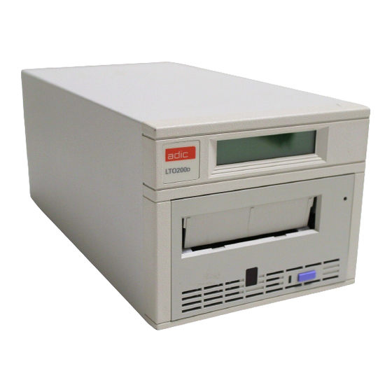
- Page 1 LTO Standalone User’s Guide LTO 200D and LTO 400D...
-
Page 2: Copyright Notice
Copyright Notice © 2003 ADIC The information contained in this document is subject to change without notice. This document contains proprietary information which is protected by copyright. All rights are reserved. No part of this document may be photocopied, reproduced, or translated to another language without prior written consent of ADIC. ADIC shall not be liable for errors contained herein or for incidental or consequential damages (including lost profits) in connection with the furnishing, performance or use of this material whether based on warranty, contract, or other legal theory. -
Page 3: Regulatory Notices
A device) or FCC Certification (for a Class A device) of this product. The following information is provided on the device or devices covered in this document in compliance with FCC regulations: Product Name: LTO 200D or LTO 400D Model number: LTO 200D or LTO 400D... -
Page 4: Ic Notice (Canada Only)
If this equipment does cause harmful interference to radio or television reception, which can be determined by turning the equipment off and on, you are encouraged to try to correct the interference by one or more of the following measures: Reorient or relocate the receiving antenna. -
Page 5: Safety Notices
Safety Notices Warnings This symbol should alert the user to the presence of "dangerous voltage" inside the product that might cause harm or electric shock. All safety and operating instructions must be read before this product is operated, and must be retained for future reference. This unit has been engineered and manufactured to assure your personal safety. - Page 6 Blank Page...
-
Page 7: Table Of Contents
Table of Contents Copyright Notice... ii Regulatory Notices ... iii FCC Notices (USA Only) ... iii Class A... iii Class B ... iii IC Notice (Canada Only) ...iv EN 55022 Compliance (Czech Republic Only) ...iv CE Notice...iv Declaration of Conformity ...iv Safety Notices...v Warnings...v Precautions...v... - Page 8 Drive R/W Diagnostic...27 Update Drive Firmware from FMR Tape...29 Create FMR Tape...31 Force a Drive Dump...33 Copy the Drive Dump to Tape [at Beginning of Tape (BOT)] ...34 SCSI Wrap Test Function ...36 Unmake FMR Tape...37 Display Error Code Log...39 Clear Error Log...40 Test Cartridge and Media...40 Fast R/W Diagnostic ...42...
-
Page 9: List Of Figures
List of Figures Figure 1-1 LTO Standalone Front Panel... 3 Figure 1-2 LTO Standalone Rear Panel ... 5 Figure 1-3 LT0 Data Cartridge ... 6 Figure 2-1 Cable Diagram for Four LTO Standalone Units... 11 Figure 2-2 SCSI ID Switch ... 12 Figure 3-1 Loading a Data Cartridge ... - Page 10 Blank Page...
-
Page 11: List Of Tables
List of Tables Table 1-1 Front Panel Controls and Indicators ... 4 Table 1-2 Rear Panel Controls and Connectors ... 5 Table 1-3 Recommended Operating, Storing, and Shipping Environment ... 6 Table 3-1 POST LCD Messages... 16 Table 3-2 Status LED States ... 17 Table 3-3 Normal Operating Condition LCD Messages... - Page 12 Blank Page...
-
Page 13: Introduction
Chapter Introduction This Chapter. . . provides a physical description of the switches, indicators and connectors on the front and rear panels of the LTO standalone. describes other requirements (additional hardware and software) needed to use the LTO standalone device. -
Page 14: Equipment Description
The LTO standalone is available with either an Ultra-2 or Ultra-3, Low Voltage Differential/Single Ended (LVD/SE) SCSI interface, or an Ultra-2, High-Voltage Differential (HVD) SCSI interface. The LTO 200D uses Ultra-2 and is available either with LVD/SE or HVD SCSI connections. -
Page 15: Front Panel Controls And Indicators
Front Panel Controls and Indicators Figure 1-1 shows the controls and indicators located on the front panel of the LTO standalone. Table 1-1 provides a brief functional description of the front panel controls and indicators. Single-character display Status LED Unload Button Single Red Dot (400D only) Figure 1-1 LTO Standalone Front Panel... -
Page 16: Table 1-1 Front Panel Controls And Indicators
Table 1-1 Front Panel Controls and Indicators Control or Indicator Purpose 2-line by 20-character LCD. Displays drive status, error messages, and POST results. Status LED Provides information about the state of the drive. The Status LED is either green or (green/amber) amber, and can be solid or flashing (refer to Table 3-2 in Chapter 3 Operation and Maintenance for a description of the Status LED states). -
Page 17: Rear Panel Controls And Connectors
Rear Panel Controls and Connectors Figure 1-2 shows the controls and connectors located on the rear panel of the LTO standalone. AC Power Connector SCSI Connectors Table 1-2 Rear Panel Controls and Connectors Control or Connector Purpose Power Switch Turns power to the unit on and off. AC Power Connector Receptacle for AC power cord. -
Page 18: Write-Protect Switch
The best storage container for unused cartridges is the original shipping container. The plastic wrapping prevents dirt from accumulating on the cartridges and partially protects them from humidity changes. You can store tape cartridges in the maximum environmental conditions for up to four weeks without damaging the data or the cartridge. -
Page 19: Handling The Cartridges
Application Software A variety of backup and data storage software is available for use with your LTO standalone. The software you use will depend upon your storage needs and the system you are using. Please check with ADIC Sales or Customer Assistance if you have a question concerning the compatibility of a particular software package. - Page 20 Blank Page Introduction...
-
Page 21: Installation
Chapter Installation This Chapter. . . Explains the steps necessary to install and test the LTO standalone devices. Provides a symbol next to each step verified as correct. -
Page 22: Unpacking And Inspecting
Unpacking and Inspecting If the operating environment differs from the storage environment by 15°C (30°F) or more, let the unit acclimate to the surrounding environment for at least 12 hours. Unpack all items from the carton. Save the packing materials in case you need to move or ship the system in the future. -
Page 23: Figure 2-1 Cable Diagram For Four Lto Standalone Units
Unit 4 SCSI ID 3 SCSI Terminator Unit 3 SCSI ID 2 SCSI Cables Unit 2 - SCSI ID 1 Host Computer Unit 1 - SCSI ID 0 Figure 2-1 Cable Diagram for Four LTO Standalone Units Installation... -
Page 24: Setting The Scsi Id
Setting the SCSI ID The SCSI ID of the LTO standalone may need to be changed, depending upon factors in the setup, operating system, and number of SCSI devices on the bus. Each device on the bus must have its own address. See Figure 2-2. The SCSI ID switch is located on the rear of the LTO standalone (see Figure 2-2). -
Page 25: Check The Scsi Bus Termination
Check the SCSI Bus Termination SCSI buses require termination at each end for proper operation. A typical external subsystem installation would be terminated at the SCSI host adapter and at the last device in the chain. If an external device is being used with an internal device (on the same channel), the SCSI host adapter would now be in the middle of the bus rather than at the end. - Page 26 Page Blank Installation...
-
Page 27: Operation And Maintenance
Chapter Operation and Maintenance This Chapter . . . describes normal operating features of the LTO standalone. explains how, and when to clean the tape head. describes how to clean the enclosure. -
Page 28: Drive Status
Power-on Self-Test and Initialization When the system power is turned on, the drive performs a Power-on Self-Test (POST) and initialization. POST is completed in approximately three minutes and the drive will respond normally to all commands. However, it may take longer for the media to be ready. Following POST completion, the Status LED will be solid green. -
Page 29: Led Indicators
After initialization, the Status LED will be in one of the five states listed in Table 3-2: Table 3-2 Status LED States LED State LTO 200D The drive has no power, is powered off, or (if C is displayed simultaneously in the single-character display) needs cleaning. -
Page 30: Normal Drive Operating Conditions
Normal Drive Operating Conditions LCD Messages Table 3-3 describes the messages displayed by the LCD during normal operation: Table 3-3 Normal Operating Condition LCD Messages Drive Operating Condition No cartridge in drive. When loading or unloading a cartridge. When cartridge is loaded. Loading the Tape Cartridge Before loading into a drive, ensure that all other items from this package are separated from the cartridge. -
Page 31: Figure 3-1 Loading A Data Cartridge
Figure 3-1 Loading a Data Cartridge Insert the tape cartridge into the slot. Grasp the cartridge so that the write-protect switch faces you as shown in the above illustration. Slide the cartridge into the tape load compartment of the drive. The load sequence begins and the front panel indicators display the following: Indicator Status LED... -
Page 32: Data Protection
Data Protection Write-Protection of the Data Cartridge While Inside the Drive The Write-Protect switch on the data cartridge can be moved while the cartridge is loaded into the drive. The drive will turn on the Write Protected LED immediately. However, if the drive is writing to the cartridge, write protect does not take effect until the write operation is completed. -
Page 33: Cleaning The Drive Head
Cleaning the Drive Head The LTO standalone is a highly sophisticated unit. No routine maintenance is required apart from periodically cleaning the drive head whenever appears on the single-character display. To clean the head, use an approved LTO Ultrium Cleaning Cartridge. Insert the cleaning cartridge in the drive following the Loading the Data Cartridge procedure described elsewhere in this chapter. - Page 34 Blank Page Operation and Maintenance...
-
Page 35: Troubleshooting And Diagnostics
Chapter Troubleshooting and Diagnostics This Chapter. . . Lists a number of common problems and the actions to take to correct them. Explains what to do when technical support is needed. -
Page 36: Troubleshooting Chart
Troubleshooting Chart If the LTO standalone fails during POST or operation, use the following table to determine the problem and the action to take: Table 4-1 Troubleshooting Chart Condition Possible cause The host system does not The system may not be configured recognize the LTO standalone to recognize the SCSI ID unit... -
Page 37: Maintenance Mode
The Status LED or the single- The LTO standalone unit has no character display never turns on. power The Status LED is on, but the The drive is defective single-character display is always blank (off). The drive will not load a tape One of the following has occurred: cartridge. -
Page 38: Putting The Lto Standalone In Maintenance Mode
SCSI Wrap Test ( Test Not Supported ( Unmake FMR Tape ( Putting the LTO Standalone in Maintenance Mode Perform the following steps to place the drive in Maintenance Mode. Verify that a cartridge is not in the drive. Press the Unload button three times within a one second interval. The state of the front panel indicators will be as shown in the following table: Indicator Status LED... -
Page 39: Exit Maintenance Mode
If the function requires you to insert a cartridge, c will appear on the single-character display. Within 60 seconds, insert a cartridge or the drive will exit Maintenance Mode. If you insert an invalid or write-protected cartridge, a blinking 7 will appear on the single-character display and the Status LED will be flashing amber and the LCD will display ERROR! Media Error after the drive loads the tape. - Page 40 Press and hold the Unload button for two seconds to select Drive R/W Diagnostics. The front panel indicators will display the following: Indicator Status LED Single-character display After 60 seconds the front panel indicators will display the following: Indicator Status LED Single-character display Within 60 seconds, insert a scratch data cartridge that is not write-protected into the drive (or the drive will exit Maintenance Mode).
-
Page 41: Update Drive Firmware From Fmr Tape
The drive takes approximately 20 minutes to complete the tests. If the diagnostics complete successfully, it will loop and begin again. Press and hold the Unload button for several seconds. When the loop ends, 0 will appear temporarily on the single-character display. - Page 42 Press the Unload button once per second until the front panel indicators display the following: Indicator Status LED Single-character display Press and hold the Unload button for two seconds to select Update Drive Firmware from FMR Tape. The front panel indicators will display the following: Indicator Status LED...
-
Page 43: Create Fmr Tape
If the update is completed successfully, the front panel indicators will display the following: Indicator Status LED Single-character display The drive will rewind and unload the FMR tape while the front panel indicators display the following: Indicator Status LED Single-character display The drive will reset itself, and the front panel indicators will display the following: Indicator Status LED... - Page 44 Press the Unload button once per second until the front panel indicators display the following: Indicator Status LED Single-character display If you select this function, the drive will overwrite existing firmware on the scratch data cartridge. Press and hold the Unload button for two seconds to select Create FMR Tape. The front panel indicators will display the following: Indicator Status LED...
-
Page 45: Force A Drive Dump
Then the drive will exit Maintenance Mode. If the drive fails to create the FMR tape, it will retry the operation twice. If the failure continues, the front panel indicators display the following: Indicator Status LED Single-character display To resolve the error, refer to Table 4-2 Error Codes, elsewhere in this chapter. To clear the error, cycle (remove, then reapply) power to the LTO standalone. -
Page 46: Copy The Drive Dump To Tape [At Beginning Of Tape (Bot)]
The single-character display will then blank (turn off), the drive will exit Maintenance Mode and the front panel indicators display the following: Indicator Status LED Single-character display You can also perform this function while the drive is in the normal operating mode. -
Page 47: Cartridge Unloading
Within 60 seconds, insert a scratch data cartridge that is not write-protected (or the drive will exit Maintenance Mode). Data on the cartridge will be overwritten. Insert only a scratch data cartridge for these tests. After you insert the cartridge, the front panel indicators will display the following: Indicator Status LED Single-character display... -
Page 48: Scsi Wrap Test Function
After clearing error (cycle power if drive error), the LCD displays the following message: Indicator Status LED Single-character display SCSI Wrap Test Function This test performs a check of the SCSI circuitry from and to the SCSI connector. To select the SCSI Wrap Test function, perform the following steps: Verify that the drive is in Maintenance Mode shown when the Status LED is solid amber. -
Page 49: Unmake Fmr Tape
If the test fails, the front panel indicators display the following: Indicator Status LED Single-character display Then the drive will exit Maintenance Mode. To resolve the error, refer to Table 4-2 Error Codes, elsewhere in this chapter. To clear the error, cycle (remove, then reapply) power to the LTO standalone. - Page 50 Within 60 seconds, insert the FMR cartridge (or the drive will exit Maintenance Mode). After you insert the cartridge, the front panel indicators display the following: Indicator Status LED Single-character display If the operation is successful, the front panel indicators display the following: Indicator Status LED Single-character display...
-
Page 51: Display Error Code Log
Display Error Code Log Use this function to display the last 10 error codes, one at a time (the codes are ordered; the most recent is presented first and the oldest– tenth–is presented last.) To select the Display Error Code Log function, perform the following steps: Verify that the drive is in Maintenance Mode by observing that the Status LED is illuminated solid amber. -
Page 52: Clear Error Log
Clear Error Log To select the Clear Error Log function, perform the following steps: Verify that the drive is in Maintenance Mode shown when the Status LED is solid amber. Press the Unload button once per second until the front panel indicators display the following: Indicator Status LED Single-character display... - Page 53 Press and hold the Unload button for two seconds to select Test Cartridge & Media. The front panel indicators display the following: Indicator Status LED Single-character display Within 60 seconds, insert the suspect cartridge (or the drive will exit Maintenance Mode). After you insert the cartridge, the front panel indicators display the following: Indicator Status LED...
-
Page 54: Fast R/W Diagnostic
If an error is detected, the front panel indicators display the following: Indicator Status LED Single-character display and your LTO standalone will exit Maintenance Mode. To resolve the error, refer to Table 4-2 Error Codes, elsewhere in this chapter. Fast R/W Diagnostic Use this function to determine whether the drive can properly load and unload cartridges, and read and write data. - Page 55 After you insert the cartridge, the front panel indicators display the following: Indicator Status LED Single-character display which will be followed by: which will alternate with: for several minutes, followed by: which will alternate with: which will loop back to Writing and continue for several minutes until the display changes to: And then it will repeat the previous steps until completed.
-
Page 56: Test Head
The drive unloads, ejects the cartridge, exits Maintenance Mode, and the front panel indicators display the following: Indicator Status LED Single-character display To resolve the error, refer to Table 4-2 Error Codes, elsewhere in this chapter. To clear the error, cycle (remove, then reapply) power to the LTO standalone. Test Head Use these tests to ensure that the drive head and tape-carriage mechanics are working correctly. - Page 57 After you insert the scratch cartridge, the front panel indicators display the following: Indicator Status LED Single-character display while the drive loads the scratch tape, followed by: The drive takes approximately 10 minutes to run the tests. If no error is detected, the test will loop and begin again. Press the Unload button.
-
Page 58: Error Codes And Messages
Error Codes and Messages Table 4-2 describes LTO standalone error codes, LCD messages, possible causes and suggested actions to correct the error. Table 4-2 Error Codes and Messages. Code LCD Message Maint Mode: Select Exit Maint Mode Error! Cooling Problem Error! Power Problem Error! - Page 59 Error! Drive/FW Prob Error! Drive Problem Error! Drive/Media Prob Error! Media Problem Error! Drive/SCSI Problem Error! Drive/SCSI Problem b, D , or Firmware or drive problem. the following: • • Power the drive off then on, then retry the operation that produced the error. If the problem persists, download new firmware and retry the operation;...
- Page 60 Troubleshooting and Diagnostics The performance of the drive is To clear this error, cycle the drive power degraded, but the drive is still or place the drive in maintenance mode. operational. . If the problem persists, replace the drive. The drive needs to be cleaned. Clean the drive.
-
Page 61: Specifications
Appendix Specifications This Appendix . . . contains specification information on the LTO standalone. -
Page 62: Dimensions
Dimensions Weight Environment Electrical BTU/Hour Temperature Humidity Vibration Shock Troubleshooting and Diagnostics LTO 200D LTO 400D ® Ultrium™ Generation 1 Contains an IBM LTO™ tape drive Ultrium 2 tape drive LTO-1 LTO-2 100 GB per cartridge (200 GB 200 GB per cartridge (400 GB... -
Page 63: Index
Index... -
Page 64: Installing
application software...7 cleaning cartridge ...21, 50 drive...21 drive head ...21 LTO Ultrium Cleaning Cartridge...21 the enclosure ...21 Clear Error Log function...25 Copy Dump to Tape function ...25 Create FMR Tape function ...25 diagnostics Drive R/W Diagnostic ...27 error codes ...46 Fast R/W Diagnostic...42 Force Drive Dump Function ...33 mode, exiting ...27... - Page 65 ...10 system configuration...24 tape cartridges allowed ...5 handling... 7 humidity ... 5 removing ... 20 storage ... 6 temperature... 5 write-protect ... 6 temperature... 50 Test Head diagnostic function ... 47 Test Head function ... 25 Test Media function... 25 troubleshooting chart...
Need help?
Do you have a question about the LTO 200D and is the answer not in the manual?
Questions and answers