Table of Contents
Advertisement
Quick Links
Advertisement
Table of Contents

Related Manuals for GRAPHTEC CE7000-40


Summary of Contents for GRAPHTEC CE7000-40
- Page 1 CUTTING PLOTTER CE7000-40/60/130/160/130AP SERVICE MANUAL CE7000-UM-251-00-9370...
- Page 3 HISTORY OF REVISIONS No. Date issued Description of revision Page Edition 19.10.25 First Printing CE7000-UM-251-9370...
- Page 4 CE7000-UM-251-9370...
-
Page 5: Table Of Contents
Installing the optional basket for CE7000-130/160 ................2-15 PARTS NAMES and FUNCTIONS ..........3-1 Parts Names and Functions ....................3-1 3.1.1 Parts Names and Functions for CE7000-40 ..................3-1 3.1.2 Parts Names and Functions for CE7000-60 ..................3-3 3.1.3 Parts Names and Functions for CE7000-130/160 ................3-5 3.1.4... - Page 6 OPERATIONS ................4-1 OPERATIONS for the CE7000-40/60/130/160 ..............4-1 4.1.1 Control Panel for the CE7000-40/60/130/160 ..................4-1 4.1.2 Menu tree for CE7000-40/60/130/160 ....................4-6 4.2 OPERATIONS for the CE7000-130AP .................4-14 4.2.1 Control Panel for the CE7000-130AP ....................4-14 4.2.2 Menu tree for CE7000-130AP .......................4-18 RECOMMENDED PARTS LIST ..........
- Page 7 Replacing the X-motor .........................7-31 7.2.13 Replacing the Main Board ........................7-35 7.2.14 Replacing the Fan ..........................7-37 7.2.15 Replacing the Drive Roller Shaft for CE7000-40/60 ................7-40 7.2.16 Replacing the Drive Roller shaft for CE7000-130/130AP/160 ............7-44 7.2.17 Replacing the Y Flexible Cable ......................7-47 7.2.18 Detaching the Push Roller assembly ....................
- Page 8 8.3 DIP Switch Settings ......................8-6 8.4 Explanation of the Values of the Main Board Settings ............8-8 8.5 Confirming the version of firmware ..................8-9 8.6 Upgrading the System Firmware ..................8-10 8.7 Clearing the NOV-RAM ......................8-13 8.8 Selecting Display Language & Length Unit ...............8-15 8.9 Copying the Adjustment value form the SUB-NVRAM .............8-16 8.10 How to Enter the Adjustment Menu ...................8-17 8.11 Adjusting the Pen Force ......................8-19...
- Page 9 10.3 Additional Outer Casing CE7000-130AP ................10-3 10.4 Control Panel ........................10-4 10.5 Pen Block CE7000-40/60/130/160 ..................10-5 10.6 Pen Block CE7000-130AP ....................10-6 10.7 Main Electrical Parts CE7000-40/60 .................. 10-7 10.8 Main Electrical Parts CE7000-130/130AP/160 ..............10-8 10.9 X Drive Parts CE7000-40/60 ....................10-9 CE7000-UM-251-9370...
- Page 10 10.17 Stand for CE7000-130AP (ST0121) ..................10-18 10.18 Basket for CE7000-60/130/160 (PG0103/104/105) .............10-19 10.19 Details of Basket Base Bracket ..................10-20 10.20 Roll Media Stoker for CE7000-40 ..................10-21 10.21 Labels ..........................10-22 10.22 Standard Accessories ...................... 10-23 11 WIRING DIAGRAMS ..............11-1 12 Target electrical component for WEEE instruction ....12-1...
-
Page 11: Introduction
51 kg 55 kg *1: Varies depending on the type of Graphtec-authorized film and the cutting conditions. *2: When using basket. *3: Describes the usable paper width. The accuracy of minimum media width is the width in parentheses ( ). -
Page 12: Ce7000-130Ap Main Specifications
1704 x 1148 x 1215 mm Weight (Approx.) 59.4 kg *1: Varies depending on the type of Graphtec-authorized film and the cutting conditions. *2: When using basket. *3: HP-GL is a registered trademark of the US Hewlett Packard Company. *4: Stand and basket are included. -
Page 13: External Dimensions
INTRODUCTION External Dimensions 1.2.1 CE7000 External Dimensions CE7000-40 Units: mm Dimensional accuracy: ±5 mm CE7000-40 External dimensions W x D x H 772 × 400 × 313 (mm) CE7000-UM-251-9370... - Page 14 INTRODUCTION CE7000-60 Units: mm Dimensional accuracy: ±5 mm CE7000-60 External dimensions W x D x H 1005 × 582 × 1092 (mm) Stand is included CE7000-UM-251-9370...
- Page 15 INTRODUCTION CE7000-130/160 Units: mm Dimensional accuracy: ±5 mm CE7000-130 CE7000-160 External dimensions W x D x H (mm) 1704 × 811 × 1215 1916 × 811 × 1215 Stand is included. CE7000-UM-251-9370...
-
Page 16: Ce7000-130Ap External Dimensions
INTRODUCTION 1.2.2 CE7000-130AP External Dimensions CE7000-130AP Units: mm Dimensional accuracy: ±5 mm CE7000-130AP External dimensions W x D1 (D2) x H (mm) 1704×1148 (811) ×1215 Stand is included. CE7000-UM-251-9370... -
Page 17: Option & Supply Parts
1 set PG0104 Used with CE7000-130 1 set PG0105 Used with CE7000-160 1 set Carrier Sheet Table OPH-A45 Used with CE7000-40/60 1 set Supply Parts Supply mane Model name Description Cutting blade holder PHP33-CB09N-HS 1 piece: for CB09U series blade. -
Page 18: Setup
Setup Setup Confirming the standard accessory When the standard accessory box is opened, confirm the following standard accessory is contained. 2.1.1 Standard accessory for the CE7000-40/60/130/160 Item Q’ty Item Q’ty Power cable 1 pc. USB cable 1 pc. 1 pc. -
Page 19: Standard Accessory For The Ce7000-130Ap
Setup 2.1.2 Standard accessory for the CE7000-130AP Item Q’ty Item Q’ty Power cable 1 pc. USB cable 1 pc. 1 pc. TO ENSURE SAFE AND CORRECT 1 set USE SETUP MANUAL Cutter Blade Manual • Various software • User’s Manual (pdf) Cutter plunger (PHP33-CB09-HS) 1 pc. -
Page 20: Assembling Stand And Basket To The Plotter
Setup Assembling stand and basket to the Plotter Do not use the electrical screwdriver when tighten the screws, otherwise it will damage the thread of screw. 2.2.1 Assembling stand for the CE7000-60 Procedure (1) Take out the following parts from the stand packing box. Foot x 2 Center bar x 1 Stand side bar x 2... - Page 21 Setup (3) Assemble the Media stocker L and R to the left and right stand sides. And when the Media stocker is assembling to the side bar, confirm the length of foot that the longer side is rear side. Insert the four M5L16 cap screws to the thread of the stand side bar by hand, and then tighten them by hand.
- Page 22 Setup (6) Set one stopper in the stock shaft. (Keep the stopper screws slightly loose.) Stock shaft Stopper (7) Put the side with the gear on the left side of the machine (looking from the back) and then slide the stock shaft into the media stocker.
-
Page 23: Assembling The Stand For Ce7000-130/160
Setup 2.2.2 Assembling the stand for CE7000-130/160 Procedure (1) Take out the following part of stand from the packing box. Foot x 2 Media stocker L and R Stand side bar x 2 Center bar x 1 Stock roller x 2 Stopper x 2 M5L16 Cap screw x 22 M5L20 Cap screw x 4... - Page 24 Setup (3) Assemble the Media stocker L and R to the left and right stand sides. Insert the eight (four on each side) M5L16 cap screws to the thread of the stand side bar by hand, and then tighten them by hand. Then fasten four M5L16 cap screws (Shorter screw) by using the Allen wrench.
- Page 25 Setup (6) Confirm the front side and the rear side for the stand by shape of center bar. Mount the plotter on the stand by inserting the positioning pins on the stand into the positioning holes on the underside of the plotter.
-
Page 26: Assembling The Stand For Ce7000-130Ap
Setup 2.2.3 Assembling the stand for CE7000-130AP Procedure (1) Take out the following part of stand from the packing box. Guide shaft Stand side assembly Foot x 2 Center bar x 1 L and R Basket tube long x 1 Basket Cloth Arm x 4 Basket tube short x 2 Basket Cloth x 1... - Page 27 Setup (2) Assemble the left and right stand side assembles and the feet. Insert the eight (four on each side) M5L16 flange cap screws to the thread of the stand side bar by hand, and then tighten them by hand. Then fasten eight (four on each side) M5L16 flange cap screws by using the Allen wrench.
- Page 28 Setup (4) Confirm the front side and the rear side for the stand by shape of stand. Mount the plotter on the stand by inserting the positioning pins on the stand into the positioning holes on the underside of the plotter. Fasten with the four M5L20 flange cap screws, using the Allen wrench.
- Page 29 Setup (7) Put on the center basket tube onto the basket tube hanger brackets, and then connect the front and rear basket tube to the basket cloth arm as shown in the picture below. (8) Attach the media guide to front of CE7000-130AP. Fasten the media guide with the three M5L10 cap screws as shown in the picture below.
-
Page 30: Installing The Optional Basket For Ce7000-60
Setup 2.2.4 Installing the optional basket for CE7000-60 Procedure (1) Take out the following part of stand from the packing box. Basket tube long x 1 Basket tube short x 2 Basket Cloth Arm x 4 M5L10 flange cap screw x 8 Allen wrench (for M5 cap screw) Basket Cloth x 1 (2) Attach the basket cloth arms to the foot of stand. - Page 31 Setup (3) Insert the basket tubes to the basket cloth as shown in the picture below. Insert the long tube to the center of basket cloth, and insert the short tubes to the front and rear. Long tube Short tube (4) Put on the center basket tube onto the basket tube hanger brackets, and then connect the front and rear basket tube to the basket cloth arm as shown in the picture below.
-
Page 32: Installing The Optional Basket For Ce7000-130/160
Setup 2.2.5 Installing the optional basket for CE7000-130/160 Procedure (1) Take out the following part of stand from the packing box. Basket tube long x 1 Basket Cloth Arm x 4 Basket tube short x 2 M5L10 flange cap screw x 8 Basket Cloth x 1 Allen wrench (for M5 cap screw) (2) Attach the basket cloth arms to the foot of stand. - Page 33 Setup (3) Insert the basket tubes to the basket cloth as shown in the picture below. Insert the long tube to the center of basket cloth, and insert the short tubes to the front and rear. Long tube Short tube (4) Put on the center basket tube onto the basket tube hanger brackets, and then connect the front and rear basket tube to the basket cloth arm as shown in the picture below.
-
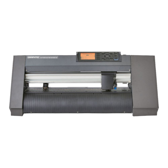
Page 34: Parts Names And Functions
PARTS NAMES and FUNCTIONS PARTS NAMES and FUNCTIONS Parts Names and Functions 3.1.1 Parts Names and Functions for CE7000-40 Front View Tool holder Tool carriage Control panel Media set lever Grit roller position guide Cutting mat RS-232C interface connector Cutting groove... - Page 35 PARTS NAMES and FUNCTIONS Rear View Accessory case Media sensors Power switch Roll-medium tray AC line inlet Roll-medium tray guide rail Roll-medium tray ���������������������A tray to set media in� Roll-medium tray guide rail ����A rail to set the roll media tray in� Power switch����������������������������Used to turn the plotter on and off�...
-
Page 36: Parts Names And Functions For Ce7000-60
PARTS NAMES and FUNCTIONS 3.1.2 Parts Names and Functions for CE7000-60 Front View Tool holder Tool carriage Control panel Grit roller position guide Media set lever Cutting mat Cutting groove Media stopper Push rollers RS-232C interface connector USB memory connector Media sensors Grit rollers USB interface connector... - Page 37 PARTS NAMES and FUNCTIONS Network (LAN) Interface connector ���������������������������������������������������Used to connect this plotter with a network (LAN) I/F� USB memory connector..USB memory dedicated connector� Rear View Accessory case Media sensors Power switch Stopper AC line inlet Stock shaft Stopper Media stocker Stand Power switch����������������������������Used to turn the plotter on and off�...
-
Page 38: Parts Names And Functions For Ce7000-130/160
PARTS NAMES and FUNCTIONS 3.1.3 Parts Names and Functions for CE7000-130/160 Front View Tool holder Tool carriage Control panel Media set lever Power switch Grit roller position guide Cutting mat Media stopper Push rollers Cutting groove Grit rollers Media sensors Control panel ���������������������������Used to access various plotter functions�... - Page 39 PARTS NAMES and FUNCTIONS Rear View Accessory case USB memory connector Push roller hold-down force switching lever RS-232C interface connector USB interface connector Network (LAN) Interface connector Stopper Media sensors AC line inlet Stopper Stock shaft Media stocker Stand AC line inlet ������������������������������Inlet where the power cable is connected� Push roller hold-down force switching lever ���������������������������������������������������Switches the hold-down force of the push roller to 3 stages of strong, medium and weak�...
-
Page 40: Parts Names And Functions For Ce7000-130Ap
PARTS NAMES and FUNCTIONS 3.1.4 Parts Names and Functions for CE7000-130AP Front View Tool holder Tool carriage Grit roller position guide Pen holder Cutting mat Media guide Media sensors Pen station Control panel Media set lever Grit rollers Power switch Media stopper Media stocker Stock shaft... - Page 41 PARTS NAMES and FUNCTIONS Pen station/Pen holder ������������A second pen is set� Media flange �����������������������������Fixes the paper roll (media) in place as per settings� Media guide ������������������������������Guides the paper (media) during the plotting/cutting process� Stock shaft �������������������������������A shaft that takes in roll media� Rear View USB memory dedicated Push roller hold-down force...
-
Page 42: Attaching A Tool
Attach a tool (cutter pen, plotter pen) to the plotter� 3.2.1 Attaching a Tool for CE7000-40/60/130/160 Attaching a Tool When mounting the tool in the tool holder, push the tool all the way into the holder until its flange contacts the upper part of the holder and then tighten the screw firmly. - Page 43 PARTS NAMES and FUNCTIONS (3) Make sure that the tool bracket is engaged on the tool’s flange, and then tighten the screw. Bracket to hold tool Flange CE7000-UM-251-9370 3-10...
-
Page 44: Attaching A Tool And A Pen For Ce7000-130Ap
PARTS NAMES and FUNCTIONS 3.2.2 Attaching a Tool and a Pen for CE7000-130AP Attaching a Tool When mounting the tool in the tool holder, push the tool all the way into the holder until its flange contacts the upper part of the holder and then tighten the screw firmly. To prevent injury, avoid touching the tool immediately after the cutting plotter is turned on or whenever the tool is moving�... - Page 45 PARTS NAMES and FUNCTIONS (2) While pushing the tool holder in the upward direction, push the tool all the way into the holder until its flange contacts the upper part of the holder. • When pushing the tool holder with your fingers, the blade tip may be protruding. Take care not to cut your fingers.
- Page 46 PARTS NAMES and FUNCTIONS Attaching a pen Attach a pen to the pen station� • Please make sure to attach the pen to the pen station when setting up a pen� • To prevent injury, avoid touching the pen immediately after the cutting plotter is turned on or whenever the pen is moving Procedure (1) Manually open the holder arm by your hand, and then attach a pen to the pen station�...
-
Page 47: Operations
OPERATIONS OPERATIONS OPERATIONS for the CE7000-40/60/130/160 4.1.1 Control Panel for the CE7000-40/60/130/160 This section explains the function of lamps and keys on the control panel. BARCODE PAUSE/MENU PAUSE/MENU lamp [2] key [1] key ORIGIN key COPY key ESC key ENTER key... - Page 48 OPERATIONS SLOW ......When pressing the POSITION key at the same time, the tool carriage moves slowly. When the “SLOW” icon is displayed on the screen, it works as a menu key. When the [SLOW] key is pressed in the READY screen, the current cutting/plotting area and the position of tool carriage are displayed.
- Page 49 OPERATIONS The condition number (Cut Condition) that has been set is displayed. Screen to set the corresponding conditions is displayed when the [PAUSE/MENU] key or [COND/TEST] key are pressed. PAUSE/MENU COND/TEST PAUSE/MENU COND/TEST It will return to default It will return to It will return to default screen It will return to default screen screen when the...
- Page 50 OPERATIONS Contents of Operation from Menu Screen In [Simple mode] on the ADVANCE (ADV.) menu, switch between Simple mode and Normal mode. In Normal mode, you will be able to change more detailed settings. Simple mode and Normal mode are independent from one another. The settings of the mode you’re currently in will take precedence.
- Page 51 OPERATIONS Operation from COND/TEST key Simple mode CONDITION screen (1-5): (Simple mode) The [COND/TEST] key brings up the SETTING screens, where you can change the media type and tool conditions. The preset cutting condition is used when the media type is selected. [COND/TEST] : This will clear the CONDITION screen and return to default screen.
-
Page 52: Menu Tree For Ce7000-40/60/130/160
OPERATIONS 4.1.2 Menu tree for CE7000-40/60/130/160 Simple mode Default Screen Condition Setting Screen 1/3 [COND/TEST] [COPY] [] CUT TEST [] CUT TEST MENU screen MEDIA SETTING (1/1) INTERFACE (1/1) [PAUSE/MENU] ADVANCE (1/1) CE7000-UM-251-9370... - Page 53 OPERATIONS Normal mode Default Screen Condition Setting Screen 1/3 [COND/TEST] [ENTE] [COPY] Condition Setting Screen 2/3 Condition Setting Screen 3/3 Continued CE7000-UM-251-9370...
- Page 54 OPERATIONS Default Screen (Continued) TOOLS SETTING MENU Screen Screen 1/4 [PAUSE/MENU] TOOLS SETTING Screen 2/4 TOOLS SETTING Screen 3/4 TOOLS SETTING Screen 4/4 Continued CE7000-UM-251-9370...
- Page 55 OPERATIONS Default Screen (Continued) ARMS SETTING MENU Screen Screen 1/2 [PAUSE/MENU] ARMS SETTING Screen 2/3 ARMS SETTING Screen 3/3 AREA PARAMETERS MENU Screen Screen 1/2 [PAUSE/MENU] AREA PARAMETERS Screen 2/2 Continued CE7000-UM-251-9370...
- Page 56 OPERATIONS Default Screen (Continued) MEDIA SETTING MENU Screen Screen 1/2 [PAUSE/MENU] MEDIA SETTING Screen 2/2 Continued CE7000-UM-251-9370 4-10...
- Page 57 OPERATIONS Default Screen (Continued) INTERFACE MENU Screen Screen 1/3 [PAUSE/MENU] [] INTERFACE Screen 2/3 When the RS-232C When the RS-232C option is installing, this option is installing, this menu is displayed. menu is displayed. The MAC address is displyed when the [] key is pressed in this menue.
- Page 58 OPERATIONS Default Screen (Continued) ADVANCE MENU Screen Screen 1/4 [PAUSE/MENU] [] ADVANCE Screen 2/4 ADVANCE Screen 3/4 ADVANCE Screen 4/4 Continued CE7000-UM-251-9370 4-12...
- Page 59 OPERATIONS Default Screen (Continued) TEST MENU Screen Screen 1/2 [PAUSE/MENU] [] TEST Screen 2/2 When the media is loading, the diagnostics is not able to perform. DATA LINK MENU Screen Screen 1/2 [PAUSE/MENU] [] DATA LINK Screen 2/2 CE7000-UM-251-9370 4-13...
-
Page 60: Operations For The Ce7000-130Ap
OPERATIONS OPERATIONS for the CE7000-130AP 4.2.1 Control Panel for the CE7000-130AP This section explains the function of lamps and keys on the control panel. CROSS CUT PAUSE/MENU PAUSE/MENU lamp [2] key [1] key ORIGIN key COPY key ESC key ENTER key Screen (LCD) [3] key [4] key... - Page 61 OPERATIONS 1, 2, 3, 4......Select the menu number displayed in the screen. POSITION keys ....Adjusts various settings, selects numerical value changes, moves the cursor, and changes the positions in the MENU screen. Reading the Screen (LCD) Information reflecting the status will be displayed in the screen of the control panel. Name of the button and corresponding function is displayed on the screen when a function is allocated to the button on the control panel.
- Page 62 OPERATIONS Default screen (Ready Screen): READY The condition number (Cut Condition) that has been set is displayed. Screen to set the corresponding conditions is displayed when the [PAUSE/MENU] key or [COND/TEST] key are pressed. PAUSE/MENU COND/TEST It will return to default It will return to screen when the default screen when...
- Page 63 OPERATIONS Contents of Operation from Menu Screen MENU screen Contents of the operation and settings that is displayed in MENU screen with [PAUSE/MENU] key is as following: [1] (TOOL) .... Set the setting for the operation of the tool. [2] (ARMS) .... Perform settings and operations related to alignment of tool and media, such as automatic registration mark scanning by ARMS.
-
Page 64: Menu Tree For Ce7000-130Ap
OPERATIONS 4.2.2 Menu tree for CE7000-130AP Default Screen Condition Setting Screen 1/3 [COND/TEST] [ENTE] [COPY] Condition Setting Screen 2/3 Condition Setting Screen 3/3 Continued CE7000-UM-251-9370 4-18... - Page 65 OPERATIONS Default Screen (Continued) TOOLS SETTING MENU Screen Screen 1/4 [PAUSE/MENU] TOOLS SETTING Screen 2/4 TOOLS SETTING Screen 3/4 TOOLS SETTING Screen 4/4 Continued CE7000-UM-251-9370 4-19...
- Page 66 OPERATIONS Default Screen (Continued) AXIS SETTING MENU Screen Screen 1/1 [PAUSE/MENU] AREA PARAMETERS MENU Screen Screen 1/1 [PAUSE/MENU] Continued CE7000-UM-251-9370 4-20...
- Page 67 OPERATIONS Default Screen (Continued) MEDIA SETTING MENU Screen Screen 1/3 [PAUSE/MENU] MEDIA SETTING Screen 2/3 MEDIA SETTING Screen 3/3 Continued CE7000-UM-251-9370 4-21...
- Page 68 OPERATIONS Default Screen (Continued) INTERFACE MENU Screen Screen 1/4 [PAUSE/MENU] [] INTERFACE Screen 2/4 When the RS-232C When the RS-232C option is installing, this option is installing, this menu is displayed. menu is displayed. The MAC address is displyed when the [] key is pressed in this menue.
- Page 69 OPERATIONS Default Screen (Continued) ADVANCE MENU Screen Screen 1/4 [PAUSE/MENU] [] ADVANCE Screen 2/4 ADVANCE Screen 3/4 ADVANCE Screen 4/4 Continued CE7000-UM-251-9370 4-23...
- Page 70 OPERATIONS Default Screen (Continued) TEST MENU Screen Screen 1/2 [PAUSE/MENU] [] TEST Screen 2/2 When the media is loading, the diagnostics is not able to perform. MEM. SETTING MENU Screen Screen 1/1 [PAUSE/MENU] [] CE7000-UM-251-9370 4-24...
-
Page 71: Recommended Parts List
RECOMMENDED PARTS LIST RECOMMENDED PARTS LIST RECOMMENDED PARTS LIST for CE7000-40/60/130/160 Part No. Description -130 -160 Remarks U792700700 Main Board, CE7, PN6043-01 U792700710 Main Board, CE7RS-232, PN6043-01 For optional RS-232C Model U792900735 Cam Sensor Board, PN5122-06 U692180314 Flexible Cable, FFC512205D... - Page 72 RECOMMENDED PARTS LIST CE7000-UM-251-9370...
-
Page 73: List Of Tools
LIST OF TOOLS LIST OF TOOLS Tools Adjustment Item Tool 1 Pen force adjustment Cutter Pen Holder (CB09) Colex gauge (50,300,500 gf) 2 Distance adjustment Scale (at least 400 mm long) 3 Pen block height adjustment 10 mm height block Scale (at least 50 mm long) 4 Firmware update PC, USB I/F cable... -
Page 75: Disassembly And Reassembly
DISASSEMBLY AND REASSEMBLY DISASSEMBLY AND REASSEMBLY Exterior Parts 7.1.1 Replacing the Right Side Cover How to detach the right side cover (1) Remove the four M4L6 binding head screws from the right side cover. (2) Detach the right side cover. Right side cover M4L6 binding head screw How to reinstall the right side cover... -
Page 76: Replacing The Control Panel Assembly
DISASSEMBLY AND REASSEMBLY 7.1.3 Replacing the Control Panel Assembly How to detach the control panel assembly (1) Detach the right side cover (Refer to subsection 7.1.1.). (2) Disconnect the control panel flexible cables from the main board. (3) Remove the three M3L6 binding head screws holding the control panel assembly. Control panel assembly M3L6 binding head screw (4) Disconnect the control panel flexible cables from the control panel board. -
Page 77: Replacing The Center Cover
(1) Detach the right side cover (Refer to subsection 7.1.1.). (2) Detach the control panel assembly (Refer to subsection 7.1.3.). (3) Remove the six M3L6 binding head screws holding the center cover. CE7000-40/60 CE7000-130/130AP/160 M3L6 binding head screw M3L6 binding head screw... -
Page 78: Replacing The Front Guide
DISASSEMBLY AND REASSEMBLY 7.1.5 Replacing the Front Guide CE7000-40 How to detach the front guide (1) Remove the three M4L5 truss head screws holding the front guide. M4L5 truss head screw Front guide (2) Detach the front guide. How to reinstall the front guide (1) Reattach the front guide in the reverse order in which it was detached. - Page 79 DISASSEMBLY AND REASSEMBLY CE7000-130/130AP/160 How to detach the front guide (1) Remove the four M4L6 binding head screws holding the front guide. (Remove the five M4L6 binding head screws holding the front guide for the CE7000-160.) (2) Pull up the bottom of front guide, and then detach the front guide. Front guide M4L6 binding head screw How to reinstall the front guide...
-
Page 80: Replacing The Rear Guide
DISASSEMBLY AND REASSEMBLY 7.1.6 Replacing the Rear Guide CE7000-40 How to detach the rear guide (1) Remove the three M4L5 truss head screws holding the rear guide. (2) Detach the rear guide. M4L5 truss head screw Rear guide How to reinstall the rear guide (1) Reattach the rear guide in the reverse order in which it was detached. - Page 81 DISASSEMBLY AND REASSEMBLY CE7000-130/130AP/160 How to detach the rear guide (1) Remove the four M4L6 binding head screws holding the rear guide. (Remove the five M4L6 binding head screws holding the rear guide for the CE7000-160.) (2) Pull up the bottom of front guide, and then detach the rear guide. M4L6 binding head screw Rear guide How to reinstall the rear guide...
-
Page 82: Replacing The Rear Writing Panel
DISASSEMBLY AND REASSEMBLY 7.1.7 Replacing the Rear Writing Panel The CE7000-130/130AP/160 only How to detach the rear writing panel (1) Detach the rear guide (Refer to subsection 7.1.6.). (2) Remove the M3L6 binding head screw from the top of the rear writing panel. M3L6 binding head screw M3L6 binding head screw Rear writing panel... -
Page 83: Replacing The Front Writing Panel Assembly
DISASSEMBLY AND REASSEMBLY 7.1.8 Replacing the Front Writing Panel Assembly The CE7000-130/130AP/160 only How to detach the front writing panel assembly (1) Detach the front guide (Refer to subsection 7.1.5.). (2) Detach the rear guide (Refer to subsection 7.1.6.). (3) Detach the rear writing panel (Refer to subsection 7.1.7.). (4) Remove the twelve M3L6 binding head screws holding the front writing panel assembly. -
Page 84: Replacing The Fan Cover
DISASSEMBLY AND REASSEMBLY 7.1.9 Replacing the Fan Cover The CE7000-130/130AP/160 only How to detach the fan cover (1) Remove the M3L6 binding head screw holding the fan cover. Fan cover M3L6 binding head screw (2) Detach the fan cover. How to reinstall the fan cover (1) Reattach the fan cover in the reverse order in which it was detached. -
Page 85: Replacing The Pen Block Cover
DISASSEMBLY AND REASSEMBLY 7.1.10 Replacing the Pen Block Cover How to detach the pen block cover (1) Remove the two M3L6 binding head screws holding the pen block cover. Pen block cover M3L6 binding head screw (2) Detach the pen block cover. When the center cover is not removed, don’t move the pen block to Y direction without the pen block cover, otherwise the center cover will cut the cables of the pen block. -
Page 86: Replacing The Push Roller
DISASSEMBLY AND REASSEMBLY 7.1.11 Replacing the Push Roller How to detach the Push Roller (1) Pull out the push roller pin from the push roller shaft by using the needle nose pliers. Push roller pin (2) Pull out the push roller shaft from the push roller arm. Push roller arm Push roller shaft (3) Detach the push roller. -
Page 87: Replacing The Cutting Mat
DISASSEMBLY AND REASSEMBLY 7.1.12 Replacing the Cutting Mat How to detach the cutting mat (1) Peel off the cutting mat from the left side of cutting mat base. Peel off the cutting mat from here. Cutting Mat How to reinstall the cutting mat (1) Clean the cutting mat base. -
Page 88: Internal Parts
How to detach the rear media sensor (1) Detach the rear guide (Refer to subsection 7.1.6.). (2) Remove the M3L10 binding head screw attaching the rear media sensor. (3) Disconnect the sensor from the connector. CE7000-40/60 CE7000-130/130AP/160 M3L10 binding head screw Rear media sensor... -
Page 89: Replacing The Registration Mark Sensor
DISASSEMBLY AND REASSEMBLY 7.2.3 Replacing the Registration Mark Sensor How to detach the registration mark sensor (1) Detach the pen block cover (Refer to subsection 7.1.10.). (2) Remove the two M2L6 binding head screw holding the registration mark sensor. M2L6 binding head screw Registration mark sensor (3) Detach the registration mark sensor from the pen block, and then disconnect the registration mark sensor cable connector from the registration mark sensor. -
Page 90: Replacing The Control Panel Board
DISASSEMBLY AND REASSEMBLY 7.2.4 Replacing the Control Panel Board How to detach the control panel board (1) Detach the control panel assembly (Refer to subsection 7.1.3.). (2) Gently lift up the lock of connector for LCD flexible cable on the control board, and then unlock the connector. -
Page 91: Replacing The Lcd
DISASSEMBLY AND REASSEMBLY 7.2.5 Replacing the LCD How to detach the LCD (1) Detach the control panel assembly (Refer to subsection 7.1.3.). (2) Detach the control panel board (Refer to subsection 7.2.4.). (3) Slide the LCD to the left from the hooks, and then detach the LCD from the control panel cover. Control panel cover Hook How to reinstall the LCD... -
Page 92: Replacing The Pen Block
(4) Detach the pen block cover (Refer to subsection 7.1.10.). (5) Disconnect the cables from connector J3004, and J3006 on the Y-relay board. (Disconnect the flexible cable from connector J3004 for the CE7000-130AP) CE7000-40/60 Pen board (Y relay board) Disconnect these cables. - Page 93 DISASSEMBLY AND REASSEMBLY Regarding the spare parts of pen block The spare parts of pen block is not including the registration mark sensor. When the pen block is replacing, remove the registration mark sensor from the used pen block. How to reinstall the pen block (1) Attach the pen block to the Y-slider.
-
Page 94: Replacing The Y-Belt
Y belt tension arm CE7000-130/130AP/160 Y belt tension spring Y belt tension arm (7) Loosen the M4L6 TP screws fixing the Y-belt tension for the CE7000-40/60. Loosen the two M4L6 TP screws fixing the Y-belt tension for the CE7000-130/130AP/160. CE6000-40/60 CE6000-130/130AP/160... - Page 95 DISASSEMBLY AND REASSEMBLY (8) Remove the four M3L6 binding head screws attaching the right and left Y-belt stopper plates to the slider. Stopper Y belt M3L6 binding head screw (9) Detach the Y-belt from the unit. How to reinstall the Y-belt (1) Shave 2 to 3 mm off both ends of the Y-belt until the wire comes out as shown below.
- Page 96 (5) Attach the pen block (Refer to subsection 7.2.6.). (6) Hang the Y belt tension spring to the Y belt tension arm. The tension spring makes the tension of Y belt automatically. CE7000-40/60 Y belt tension spring Y belt tension arm...
- Page 97 DISASSEMBLY AND REASSEMBLY (8) Tighten the M4L6 TP screws fixing the Y-belt tension to keep the Y belt tension for the CE7000-40/60. Tighten the two M4L6 TP screws fixing the Y-belt tension to keep the Y belt tension for the CE7000- 130/130AP/160.
-
Page 98: Replacing The Push Roller Sensor Board
DISASSEMBLY AND REASSEMBLY 7.2.8 Replacing the Push Roller Sensor Board How to detach the push roller sensor board (1) Detach the control panel assembly (Refer to subsection 7.1.3.). (2) Detach the center cover (Refer to subsection 7.1.4.). (3) Detach the pen block (Refer to subsection 7.2.6.). (4) Remove the two M3L6 binding head screws attaching the push roller sensor bracket to the slider. -
Page 99: Replacing The Y-Relay Board
(2) When new Y-relay board is installed to the CE7000-130/130AP/160, cut off the Y-relay board as shown in the picture below. Cut off the Y relay board at this line. Y relay board for the CE7000-130/130AP160 Y relay board for the CE7000-40/60 CE7000-UM-251-9370 7-25... -
Page 100: Replacing The Cam Sensor Board
7.2.10 Replacing the Cam Sensor board How to detach the cam sensor board (1) Detach the right side cover (Refer to subsection 7.1.1.). (2) Remove the M3L6 binding head screw holding the cam sensor board. CE7000-40/60 M3L6 binding head screw Cam sensor board CE7000-130/130AP/160... - Page 101 DISASSEMBLY AND REASSEMBLY How to reinstall the cam sensor board (1) Reattach the cam sensor board in the reverse order in which it was detached. (2) Confirm the dog of cam is not touching to the sensor of cam sensor board after cam sensor board was attached.
-
Page 102: Replacing The Y-Motor
(3) Disconnect the Y-motor power cable from Y motor power relay cable connector. (4) Mark the position of screws which are holding the Y motor as shown in the picture below. CE7000-40/60 Mark the position of screws which are holding the Y motor. - Page 103 DISASSEMBLY AND REASSEMBLY (5) Remove the three M3L6 binding head screws holding the Y-motor. CE7000-40/60 M3L6 binding head screw Y Motor CE7000-130/130AP/160 M3L6 binding head screw Y Motor (6) Detach the Y-motor. (7) Loosen the two M3L4WP set screws to detach the Y-motor pulley.
- Page 104 DISASSEMBLY AND REASSEMBLY How to reinstall the Y-motor (1) Attach the Y-motor pulley to the Y-motor at the following position. Y motor pulley 1.5 mm Y motor (2) Tighten the two M3L4WP set screws that hold the Y-motor pulley. (3) Spread a suitable quantity of Loctite 222 on the two M3L4WP set screws that hold the Y-motor pulley. (4) Attach the Y-motor to the Y-motor bracket.
-
Page 105: Replacing The X-Motor
(5) Mark the position of screws which are holding the X motor as shown in the picture below. Mark the position of screws which are holding the X motor. (6) Remove the three M3L6 binding head screws holding the X-motor. (7) Detach the X motor from the front of CE7000-40/60. X motor X motor encoder cable... - Page 106 DISASSEMBLY AND REASSEMBLY (8) Disconnect the X motor power relay cable and the X motor encoder cable from the X motor. (9) Loosen the two M3L4WP set screws holding the X-motor pulley, then detach the X-motor pulley. X motor pulley X motor M3L4WP set screw How to reinstall the X-motor...
- Page 107 DISASSEMBLY AND REASSEMBLY CE7000-130/130AP/160 How to detach the X-motor (1) Detach the right side cover (Refer to subsection 7.1.1.). (2) Mark the position of screws which are holding the X motor as shown in the picture below. Mark the position of screws which are holding the X motor. (3) Remove the three M3L6 binding head screws holding the X-motor, then detach the X-motor from the hole of right side plate.
- Page 108 DISASSEMBLY AND REASSEMBLY How to reinstall the X-motor (1) Attach the X-motor pulley to the X-motor at the following position. Tighten the two M3L4WP set screws that hold the X-motor pulley. X motor pulley 3.5 mm X motor (2) Spread a suitable quantity of Loctite 222 on the two M3L4WP set screws that hold the X-motor pulley. (3) Attach the X motor to the right side plate.
-
Page 109: Replacing The Main Board
DISASSEMBLY AND REASSEMBLY 7.2.13 Replacing the Main Board CE7000-40/60 How to detach the main board (1) Detach the right side cover (Refer to subsection 7.1.1.). (2) Disconnect all the cables and flexible cables from their connectors on the main board. - Page 110 DISASSEMBLY AND REASSEMBLY How to reinstall the main board (1) Attach the spacer to the main board. Main board Spacer (2) Reattach in the reverse order in which it was detached. (3) Confirm the wiring for cables (Refer to subsection 7.4.). (4) Perform all adjustments required for main board (Refer to subsection 8.2.).
-
Page 111: Replacing The Fan
(4) Remove the two M3L35 binding head screws holding the vacuum fan as shown in the figure below. M3L35 binding head screw (5) Detach the vacuum fan from the front of CE7000-40/60. How to reinstall the fan (1) Reattach in the reverse order in which it was detached. - Page 112 DISASSEMBLY AND REASSEMBLY CE7000-130/130AP/160 How to detach the vacuum fan 1 (1) Detach the right side cover (Refer to subsection 7.1.1.). (2) Detach the front guide (Refer to subsection 7.1.5.). (3) Disconnect the cable of vacuum fan from the J1007 connector on the main board. (4) Remove the M3L6 binding head screw holding the fan cover on the bottom of plotter, and then detach it.
- Page 113 DISASSEMBLY AND REASSEMBLY How to detach the vacuum fan 2 (1) Detach the front guide (Refer to subsection 7.1.5.). (2) Disconnect the cable of vacuum fan from the fan relay connector. Fan relay cable connector (3) Remove the M3L6 binding head screw holding the fan cover on the bottom of plotter, and then detach it. M3L6 binding head screw Fan cover (4) Remove the two M3L35 binding head screws holding the vacuum fan as shown in the figure below.
-
Page 114: Replacing The Drive Roller Shaft For Ce7000-40/60
DISASSEMBLY AND REASSEMBLY 7.2.15 Replacing the Drive Roller Shaft for CE7000-40/60 How to detach the drive roller shaft (1) Detach the right side cover (Refer to subsection 7.1.1.). (2) Detach the left side cover (Refer to subsection 7.1.2.). (3) Detach the front guide (Refer to subsection 7.1.5.). - Page 115 DISASSEMBLY AND REASSEMBLY (9) Remove the M3L6 binding head screw holding the Y-motor cover, and then detach the Y-motor cover. Y Motor Cover M3L6 binding head screw (10) Mark the position of screws which are holding the X motor as shown in the picture below. Mark the position of screws which are holding the X motor.
- Page 116 (15) Remove the two M3L6 TP screws holding the bearing, and then detach the bearing from the the drive roller shaft. M3L6 TP screw Bearing (16) Slide out the drive roller shaft from the CE7000-40/60. Drive roller shaft CE7000-UM-251-9370 7-42...
- Page 117 DISASSEMBLY AND REASSEMBLY How to reinstall the drive roller shaft (1) Reattach in the reverse order in which it was detached. (2) Perform the X-drive belt tension adjustment (Refer to subsection 7.3.3.). (3) Perform the Y-drive belt tension adjustment (Refer to subsection 7.3.2.). (4) Reattach the other parts in the reverse order in which they were detached.
-
Page 118: Replacing The Drive Roller Shaft For Ce7000-130/130Ap/160
DISASSEMBLY AND REASSEMBLY 7.2.16 Replacing the Drive Roller shaft for CE7000-130/130AP/160 How to detach the drive roller shaft (1) Detach the right side cover (Refer to subsection 7.1.1.). (2) Detach the left side cover (Refer to subsection 7.1.2.). (3) Detach the front guide (Refer to subsection 7.1.5.). (4) Detach the rear guide (Refer to subsection 7.1.6.). - Page 119 DISASSEMBLY AND REASSEMBLY (10) Remove the M3L6 binding head screws holding the bearing covers and detach the bearing covers from the pillow blocks. (Don’t loosen the M3L6 binding head screws holding the pillow blocks.) CE7000-130/130AP CE7000-160 Drive roller shaft M3L6 binding head screw Bearing cover Pillow block (11) Slide out the X-drive roller shaft to the left side and detach the X drive roller shaft from the unit.
- Page 120 DISASSEMBLY AND REASSEMBLY (3) When the X drive pulley is installing to the drive roller shaft, tighten the four M3L4 set screws while pushing the drive pulley and the drive roller shaft to the following direction. X drive pulley Drive roller shaft (4) Spread a suitable quantity of Loctite 222 on the four M3L4WP set screws holding the X-drive pulley.
-
Page 121: Replacing The Y Flexible Cable
(2) Detach the control panel assembly (Refer to subsection 7.1.3.). (3) Detach the center cover (Refer to subsection 7.1.4.). (4) Disconnect the Y flexible cable from the main board. (5) Release the cable ties holding the Y flexible cable. CE7000-40/60 CE7000-130/130AP/60 Cable tie Cable tie... - Page 122 (2) Move the pen block to the left end. (3) Fit the Y-flexible cable into the Y-rail as shown below. Make a 10 mm slack from the left end of the Y relay board (Y flexible cable bracket). CE7000-40/60 CE7000-130/130AP/160 Y relay board...
-
Page 123: Detaching The Push Roller Assembly
DISASSEMBLY AND REASSEMBLY 7.2.18 Detaching the Push Roller assembly CE7000-40/60 How to detach the Push Roller assembly (1) Detach the right side cover (Refer to subsection 7.1.1.). (2) Detach the left side cover (Refer to subsection 7.1.2.). (3) Disconnect the Control Panel Flexible cable form the main board. - Page 124 DISASSEMBLY AND REASSEMBLY (7) Remove the two M3L10 TP screws holding the cam set lever, and then slide it to the right side. M3L10 TP screw Set lever (8) Remove the M3L10 TP screws holding the left cam shaft holder, and then detach the cam shaft holder from the cam shaft.
- Page 125 DISASSEMBLY AND REASSEMBLY (11) Confirm the position of set-lever is the unloaded position. (12) Pull the cam shaft to the right side (left side from the rear view.), until the left side of cam shaft is reached to the notch of Y rail. Cam shaft (13) Slide the push roller assembly to the notch of Y rail, and then detach the push roller assembly from the Y rail.
- Page 126 DISASSEMBLY AND REASSEMBLY CE7000-130/130AP/160 How to detach the Push Roller assembly (1) Detach the right side cover (Refer to subsection 7.1.1.). (2) Remove the two M4L10 binding head screws holding the cam sensor dog, and then detach it from the cam shaft.
- Page 127 DISASSEMBLY AND REASSEMBLY (5) Mark the position of push roller stopper as shown in the picture bellow, and then loosen the screw holding the push roller stopper. Stopper screw Mark the position of stopper here. (6) Slide the push roller stopper to the left side of notch of Y rail. Notch of Y rail Slide the stopper to here.
- Page 128 DISASSEMBLY AND REASSEMBLY How to reinstall the Push Roller Assembly (1) Reattach the push roller assembly in the reverse order in which it was detached. (2) When the cam shaft is inserting to the cam, confirm the direction of cam that push-roller is possible to lift up or down by the set-lever.
-
Page 129: Replacing The Push Roller Base
DISASSEMBLY AND REASSEMBLY 7.2.19 Replacing the Push Roller base CE7000-40/60 How to detach the Push Roller base (1) Detach the push roller assembly (Refer to subsection 7.2.18.). (2) Release the spring from the push roller arm. Spring Push roller arm (3) Detach the cam from the push roller assembly. - Page 130 DISASSEMBLY AND REASSEMBLY CE7000-130//130AP/160 How to detach the Push Roller base Don’t loosen any screws on the push roller assembly. (1) Detach the push roller assembly (Refer to subsection 7.2.18.). (2) Release the spring from the push roller arm. Spring Push roller arm (3) Detach the cam from the push roller assembly.
- Page 131 DISASSEMBLY AND REASSEMBLY (5) Remove the E-ring holding the push roller base shaft, and then detach the push roller base shaft from the push roller base. Push roller base E-ring Push roller base shaft (6) Detach the push roller arm and the push roller arm spring from the push roller base. Push roller base Push roller arm spring Push roller arm...
-
Page 132: Replacing Power Supply Board
(1) Detach the left side cover (Refer to subsection 7.1.2.). (2) Disconnect all cables from the power supply board. (3) Remove the four M3L6 binding head screws holding the power supply board, and then detach it. CE7000-130/130AP/160 CE7000-40/60 M3L6 binding head screw M3L6 binding head screw Power supply board... -
Page 133: Belt Tension Adjustments
How to adjust the Y-belt tension (1) Move the pen block to the right side end. (2) Loosen the (two) tension fixing screw(s), then tension spring makes the Y belt tension automatically. CE7000-40/60 CE7000-130/130AP/160 Tension fixing screw Tension fixing screw (3) Tighten the (two) tension fixing screw(s) to keep the Y belt tension. -
Page 134: Y-Drive Belt Tension Adjustment
Y-Drive Belt Tension Adjustment How to adjust the Y-Drive belt tension (1) Tighten the three screws attaching the Y motor at the marking position, which was marked when detaching the Y motor. CE7000-40/60 Marking position Y Motor CE7000-130/130AP/160 Marking position... - Page 135 CE7000-130/130AP/160 (2) Adjust the position of Y-motor that Y drive belt is pushed 2 mm by 750 g force for the CE7000-40/60. Adjust the position of Y-motor that Y drive belt is pushed 2 mm by 500 g force for the CE7000- 130/130AP/160.
-
Page 136: X-Drive Belt Tension Adjustment
7.3.3 X-Drive Belt Tension Adjustment How to adjust the X-Drive belt tension (1) Tighten the three screws attaching the X motor at the marking position, which was marked when detaching the X motor. CE7000-40/60 CE7000-130/130AP/160 Marking position Marking position CE7000-UM-251-9370... - Page 137 CE7000-130/130AP/160 (2) Adjust the position of X-motor that X drive belt is pushed 2 mm by 550 g force for the CE7000-40/60. Adjust the position of X-motor that X drive belt is pushed 2 mm by 600 g force for the CE7000- 130/130AP/160.
-
Page 138: Confirming The Cable Wiring
The cables for X and Y motor has same connectors, therefore do not connect those cables incorrectly. The X motor has the power cable and the encoder cable, connect these cables to correct connectors as shown in the picture below. CE7000-40/60 CE7000-130/130AP/160 X motor... - Page 139 The cables for X and Y motor has same connectors, therefore do not connect those cables incorrectly. The Y motor has the power cable and the power-relay cable and the encoder cable. Connect these cables to correct connectors as shown in the picture below. CE7000-40/60 CE7000-130/130AP/160 Y motor...
- Page 140 Confirming the flexible cable wiring from the cam sensor board to the main board The flexible cable has a right side and a wrong side, connect the flexible cable correctly as shown in the picture below. CE7000-40/60 Cam sensor board Cam sensor flexible cable Confirm the printed side, which is facing to the bottom.
- Page 141 Confirming the flexible cable wiring (Y flexible cable) from the Y relay board to the main board The flexible cable has a right side and a wrong side, connect the flexible cable correctly as shown in the picture below. CE7000-40/60 Y relay board Y Flexible cable Confirm the printed side, which is facing to the up.
- Page 142 The flexible cable has a right side and a wrong side, connect the flexible cable correctly as shown in the picture below. [Main board side] CE7000-40/60 Control panel flexible cable Confirm the printed side, which is facing to the rear.
- Page 143 Confirming the flexible cable wiring from the push roller sensor board to the Y relay board The flexible cable has a right side and a wrong side, connect the flexible cable correctly as shown in the picture below. [Y relay board side] CE7000-40/60 CE7000-130/130AP/60 Y relay board Y relay board...
-
Page 144: Electrical Adjustment
Electrical Adjustment Electrical Adjustment List of Items Requiring Readjustment If you replaced any of the units listed in the table below or altered their sensor positions, be sure to readjust the corresponding items. Registration Unit name Media Drive Main board sensor mark drive... -
Page 145: Flowchart Of The Adjustment Sequence
Electrical Adjustment Flowchart of the Adjustment Sequence 8.2.1 When the main board was replaced (Normal procedure) When the main board was exchanged, copy adjustment values to the main board from the NV-RAM (memory) of cam sensor board by the following procedure. Clear the NOV-RAM for corresponding model (Refer to subsection 8.7.). -
Page 146: When The Main Board Was Replaced (The Adjustment Values Could Not Copy.)
Input the pen force adjustment values (Refer to subsection 8.11.1.). Input the Distance and the Perpendicularity Accuracy adjustment values (Refer to subsection 8.12.1.). CE7000-40/60/130/160 only: Adjust the Registration Mark Sensor Sensitivity (Refer to subsection 8.13.). Input the Offset of Registration Mark Sensor adjustment value (Refer to subsection 8.14.1.). -
Page 147: When The Pen Block Was Replaced
When the pen block was exchanged, perform the following adjustments. Adjust the pen force adjustment values (Refer to subsection 8.11.2.). CE7000-40/60/130/160 only: Adjust the Registration Mark Sensor Sensitivity (Refer to subsection 8.13.). Adjust the Offset of Registration Mark Sensor (Refer to subsection 8.14.2.). -
Page 148: When The Cam Sensor Board Was Replaced
Electrical Adjustment 8.2.6 When the cam sensor board was replaced When the cam sensor board was exchanged, perform the following adjustment. Back up the adjustment value to the SUB-NVRAM (Refer to subsection 8.19.). End of adjustment 8.2.7 When the 2nd pen of holder or station was replaced The CE7000-130AP only. -
Page 149: Dip Switch Settings
Electrical Adjustment DIP Switch Settings The location of DIP switch on the main board CE7000-40/60 CE7000-130/130AP/160 CE7000-UM-251-9370... - Page 150 This setting depends on the model. Dip Switch (SW1) Model OFF OFF OFF OFF OFF OFF OFF OFF CE7000-40 1 2 3 4 5 6 7 8 ON OFF OFF OFF OFF OFF OFF OFF CE7000-60 1 2 3 4 5 6 7 8...
-
Page 151: Explanation Of The Values Of The Main Board Settings
When the SUB-NVRAM of adjustment values are not able to copy to the main board, use this values. If you have changed any values by making adjustments, record those values for the next maintenance check. CE7000-40/60 CE7000-130/130AP/160 150 240 0.2 2.10 351.78... -
Page 152: Confirming The Version Of Firmware
Electrical Adjustment Confirming the version of firmware Confirm the version of firmware by the following procedure. How to confirm the version of firmware (1) Turn off the power for the CE7000 if power was turned on. (2) Turn on the power for the CE7000. (3) The firmware version is displayed while the initialization routine. (4) Confirm the firmware version. CE7000-UM-251-9370... -
Page 153: Upgrading The System Firmware
Electrical Adjustment Upgrading the System Firmware To upgrade the system firmware, prepare the following items. CE7000-40/60/130/160 • Windows PC :The firmware is able to update from the Windows PC only. • USB cable • CE7000_V***_R****.X :CE7000 firmware ® • SEND.EXE :Utility to transfer files using Windows • OPS662 :USB Driver software for the CE7000 (version must later than V3.70.) CE7000-130AP • Windows PC :The firmware is able to update from the Windows PC only. - Page 154 Electrical Adjustment (4) Transfer firmware data from the personal computer. Execute SEND.EXE. Select the folder for the firmware, then select the firmware file. The File name box shows the firmware file name. Select the all files. Select the output device. Confirm the active device of CE7000 at the "Device and Printer" menu in the WINDOWS before selecting the output device. (5) Press print button to output the system firmware file to the CE7000 after all settings are set in above step. (6) While updating the firmware, the following menus will be displayed. CE7000-UM-251-9370 8-11...
- Page 155 Electrical Adjustment (7) When the updating is completed, the plotter will start the initialization routine. The firmware version is displayed during the initialization routine. Check the firmware version that you upgraded. (8) Turn off the power. CE7000-UM-251-9370 8-12...
-
Page 156: Clearing The Nov-Ram
(2) Set SW1 to the NOV-RAM clear mode as shown below. Dip Switch (SW1) Model OFF OFF OFF ON OFF OFF OFF OFF CE7000-40 1 2 3 4 5 6 7 8 ON OFF OFF ON OFF OFF OFF OFF CE7000-60... - Page 157 (7) Return the SW1 setting to the normal mode as shown below. Dip Switch (SW1) Model OFF OFF OFF OFF OFF OFF OFF OFF CE7000-40 1 2 3 4 5 6 7 8 ON OFF OFF OFF OFF OFF OFF OFF CE7000-60...
-
Page 158: Selecting Display Language & Length Unit
Electrical Adjustment Selecting Display Language & Length Unit The Language selection menu and the Length Unit selection menu are displayed at the first power on. Select the Language and the Length Unit when the Language selection is displayed. And when you are going to enter the adjustment mode select the language to English and then select the Length unit to METRIC. -
Page 159: Copying The Adjustment Value Form The Sub-Nvram
Electrical Adjustment Copying the Adjustment value form the SUB-NVRAM There is the SUB-NVRAM on the cam sensor board of CE7000. This SUB-NVRAM is memorizing all adjustment values for the CE70000. All adjustment values are able to copy to the new main board from the SUB-NVRAM of cam sensor board when the main board is replacing. -
Page 160: How To Enter The Adjustment Menu
Electrical Adjustment 8.10 How to Enter the Adjustment Menu (1) Turn on the power while pressing the SLOW and ENTER keys. After turning on the power, press the SLOW and the ENTER keys simultaneously within 2 seconds. At the ready mode, while the ENTER key is pressing, press the ORIGIN key. And then the plotter is reset. - Page 161 Electrical Adjustment Adjustment Menu List Sensor & Key test. Pen pressure adjustment. Distance adjustment. Suffix setting (Set to STD for standard model, Do not change.). Registration mark sensor sensitivity adjustment. Registration mark sensor position adjustment. Home sensor position adjustment (Do not change.). Registration mark sensor level confirmation. Dots check for the LCD. Running test for X and Y directions. Registration mark sensor hood condition (Do not change.).
-
Page 162: Adjusting The Pen Force
Electrical Adjustment 8.11 Adjusting the Pen Force This adjustment will set the pen force. Required jigs and tools when the pen block assembly was replaced • Correx Dial Tension gauges (1000 g, 500 g, 300 g, 50 g) • Cutter plunger 8.11.1 Inputting the pen force from the recorded value Perform this procedure if adjustment values could not copy from the SUB-NVRAM when replacing the main board. - Page 163 Electrical Adjustment (7) Press the F2 key to display the following menu. Don’t press the F1 (AUTO with gauger), this mode is used at production line only. If the F1 key pressed, readjust the pen force by the manual adjustment. (8) Press the ENTER key to display the following menu.
-
Page 164: Adjusting The Pen Force From The Measured Force
Electrical Adjustment 8.11.2 Adjusting the pen force from the measured force When the pen block assembly was replaced, you must measure the pen force by using the Correx Dial Tension gauge and adjust pen force to the target force with following procedure. Required jigs and tools •... - Page 165 Electrical Adjustment (9) Press the ENTER key to display the following menu. Use the UP or DOWN position key to change the force setting. (10) The pen is lowered. Use the Correx Dial Tension gauges to measure the actual force as shown in the picture below.
- Page 166 Electrical Adjustment (24) Press the ENTER key when the measured value is within the specification range (458±15g). Note: When adjusting the pen force, it is important to do it quickly. Delaying the pen force adjustment changes the temperature of the actuator and causes artificially lower readings. When this happens the actual pen force may be higher than the specification. This is especially true for the upper pen force adjustment. (25) The following menu is displayed. (26) Turn off the power to exit from the adjustment menu. (When other adjustment is going to perform continuously it does not need to turn off the power.) Specification of the actual pen force Specified pen force...
-
Page 167: Adjusting The Distance Accuracy
Electrical Adjustment 8.12 Adjusting the Distance Accuracy This adjustment will set the distance and the perpendicularity accuracy. 8.12.1 Inputting the distance accuracy from the recorded value Perform this procedure if adjustment values could not copy from the SUB-NVRAM when replacing the main board. - Page 168 Electrical Adjustment (8) Press the ENTER key to set the value, then the following menu is displayed. (9) Press the F3 key to display the following menu. UP and down allow keys changes value Slow key changes unit (10) Input the Y-axis distance adjustment value from the recorded value of Y. (11) Press the ENTER key to set the value, then the following menu is displayed.
-
Page 169: Adjusting The Distance Accuracy From The Measured Distance
Electrical Adjustment 8.12.2 Adjusting the distance accuracy from the measured distance When the drive roller was replaced, adjust the distance accuracy from the measuring distance. Required jigs and tools • A3 or larger size sheet of paper • A ruler which is measured longer than 360 mm •... - Page 170 Electrical Adjustment (9) Press the F3 key to display the following menu. Regarding the DRAW PATTERN and the ADJUSTED PATTERN: The DRAW PATTERN writes the original pattern which is not adjusted, therefore the adjustment distance must measure from this pattern. And this pattern writes always same distance even if adjusted values are input.
- Page 171 Electrical Adjustment (14) Press the ENTER key to set the value, then the following menu is displayed. (15) Press the F3 key to display the following menu. UP and down allow keys changes value Slow key changes unit (16) Input the Y-axis distance adjustment value by the actual measuring value of Y. (If you measured the 249.0 mm for the Y-axis, input the 249.00.) (17) Press the ENTER key to set the value, then the following menu is displayed.
-
Page 172: Adjusting The Registration Mark Sensor Sensitivity
Electrical Adjustment 8.13 Adjusting the Registration Mark Sensor Sensitivity This adjustment will set the registration mark senor sensitivity. Perform this procedure if adjustment values could not copy from the SUB-NVRAM when replacing the main board. When the registration mark sensor or the main board was replaced, this adjustment must be performed. Preparation Print out the registration mark sensor sensitivity adjustment sheet which is on the last page of this chapter to A4 size white copy paper. - Page 173 Electrical Adjustment (5) Press the PAUSE/MENU key to display the following menu. (6) Press the Right position key to display the adjustment menu shown below. (7) Press the Up position key to display the following menu. (8) Press the F1 key to display the following menu. (9) Press the F2 key to display the following menu.
- Page 174 Electrical Adjustment (12) Press the ENTER key to store the setting. (13) Turn off the power to exit from the adjustment menu. (When other adjustment is going to perform continuously it does not need to turn off the power.) CE7000-UM-251-9370 8-31...
-
Page 175: Adjusting The Offset Of Registration Mark Sensor
Electrical Adjustment 8.14 Adjusting the Offset of Registration Mark Sensor This adjustment will set the offset of tool and the registration mark senor position. Preparation When the registration mark sensor was replaced or removed, print out the target sheet which is on the last page of this chapter to A4 size white copy paper. - Page 176 Electrical Adjustment (4) Press the Right position key to display the adjustment menu shown below. (5) Press the Up position key to display the following menu. (6) Press the F2 key to display the following menu. (7) Press the F2 key to display the following menu. UP and down allow keys changes value (8) Input the X-offset adjustment value from the recorded value of registration mark of X offset.
- Page 177 Electrical Adjustment (12) Press the ENTER key to set the Y offset, the following menu is displayed. (13) Press the ENTER key, the following menu is displayed. (14) Turn off the power to exit from the adjustment menu. (When other adjustment is going to perform continuously it does not need to turn off the power.) CE7000-UM-251-9370 8-34...
-
Page 178: Adjusting The Registration Mark Sensor Offset Position From The Measured Values
Electrical Adjustment 8.14.2 Adjusting the registration mark sensor offset position from the measured values When the registration mark sensor was replaced, the registration mark sensor sensitivity adjustment must be performed before this adjustment. When the registration mark sensor was replaced or detached, this adjustment must be performed. Required jigs and tools •... - Page 179 Electrical Adjustment (7) Press the Right position key to display the adjustment menu shown below. (8) Press the Up position key to display the following menu. (9) Press the F2 key to display the following menu. (10) Press the F1 key (MANUAL) to display the following menu. (11) Press the F2 key (SCAN) to display the following menu.
- Page 180 Electrical Adjustment (13) Press the ENTER key after the tool position was moved to the above area. The plotter will scan the cross mark target, and then it will cut the cross mark target. When the offset is correct, it will cut When the offset is not correct, it will onto the cross mark target.
- Page 181 Electrical Adjustment (19) Press the ENTER key, after it is input. (20) Perform the steps from (10) to (13) to confirm the offset was adjusted correctly. (21) Press the ENTER key, the following menu is displayed. (22) Turn off the power to exit from the adjustment menu. (When other adjustment is going to perform continuously it does not need to turn off the power.) CE7000-UM-251-9370 8-38...
-
Page 182: Adjusting The X Media Sensor Position
Electrical Adjustment 8.15 Adjusting the X Media Sensor Position This adjustment will set the registration mark sensor position and the X media sensor position. 8.15.1 Inputting the X Media Sensor Position from the recorded value Perform this procedure if adjustment values could not copy from the SUB-NVRAM when replacing the main board. - Page 183 Electrical Adjustment (7) Press the Down position key until the following menu is displayed. (8) Press the F3 key to display the following menu. (9) Press the F2 key to display the following menu. UP and down allow keys changes value (10) Input the front X media sensor adjustment value from the recorded.
- Page 184 Electrical Adjustment (15) Press the ENTER key to display the following menu. (16) Turn off the power for the plotter. (When other adjustment is going to perform continuously it does not need to turn off the power.) CE7000-UM-251-9370 8-41...
-
Page 185: Adjusting The X Media Sensor Position
Electrical Adjustment 8.15.2 Adjusting the X Media Sensor Position When the media sensor was replaced or detached, perform this adjustment. Preparation Make a adjustment target sheet as shown in the picture below. Make a 100 mm x 20 mm rectangle hole on the A4 copy paper to the following position. Make a 100 mm X 20 mm rectangle hole to the A4 size of copy paper at the showing position. - Page 186 Electrical Adjustment (5) Press the PAUSE/MENU key to display the following menu. (6) Press the Right position key to display the following menu. (7) Press the Down position key until the following menu is displayed. (8) Press the F3 key to display the following menu. (9) Press the F1 key, and then the plotter scan the adjustment target sheet, and then it automatically adjust the front and the rear media sensor position with the registration mark sensor.
-
Page 187: Adjusting The 2Nd Pen Exchange Position (Ce7000-130Ap)
Electrical Adjustment 8.16 Adjusting the 2nd Pen Exchange position (CE7000-130AP) This adjustment will set the 2nd pen exchange position for the CE7000-130AP. 8.16.1 Inputting the 2nd Pen Exchange position from the recorded value Perform this procedure if adjustment values could not copy from the SUB-NVRAM when replacing the main board for the CE7000-130AP. - Page 188 Electrical Adjustment (7) Press F3 key to display the following menu. Input Y exchange position value using the up or the down position key. (8) Input the Y exchange position value from the recorded. (9) Press the ENTER key to display the following menu. (10) Press F4 key to display the following menu.
-
Page 189: Adjusting The 2Nd Pen Exchange Position
Electrical Adjustment 8.16.2 Adjusting the 2nd Pen Exchange position When the pen block was removed or replaced, perform this adjustment. When the 2nd pen station was removed or replaced, perform this adjustment. When the 2nd pen holder was removed or replaced, perform this adjustment. How to adjust the 2nd Pen Exchange position (1) Turn on the power while pressing the SLOW and the ENTER keys. - Page 190 Electrical Adjustment (8) Press the F2 key to display the following menu. (9) Press the F2 key to move the pen carriage to the exchange position. And then confirm the gap between the 2nd pen holder and the 2nd pen station. The gap must be 1.1 mm. When this gap is too far or too close, the 2nd pen will not exchange correctly. And confirm the height between the 2nd pen holder and the 2nd pen station.
- Page 191 Electrical Adjustment (14) Mount a fiber tip pen in the 2nd pen station. (15) Press the right key to confirm that the pen exchanging is performed correctly. (16) If the pen exchanging is performed correctly, press the ENTER key, the following menu is displayed. (17) Turn off the power for the plotter. (When other adjustment is going to perform continuously it does not need to turn off the power.) CE7000-UM-251-9370 8-48...
-
Page 192: Adjusting The Spacing Between Tool 1 And Tool 2 (Ce7000-130Ap)
Electrical Adjustment 8.17 Adjusting the Spacing Between Tool 1 and Tool 2 (CE7000-130AP) This adjustment will set the spacing between tool 1 and tool 2. 8.17.1 Inputting the Spacing Between Tool 1 and Tool 2 from the recorded value Perform this procedure if adjustment values could not copy from the SUB-NVRAM when replacing the main board. - Page 193 Electrical Adjustment (7) Press the F3 key to display the following menu. Set the X-offset value by using the UP or DOWN position key. (8) Input the X-offset value from the recorded. (9) Press the ENTER key after offset value is input, the following menu is displayed. (10) Press the F4 key to display the following menu.
- Page 194 Electrical Adjustment 8.17.2 Adjusting the Spacing Between Tool 1 and Tool 2 When the pen block was replaced or the 2nd Pen was removed, perform this adjustment. Preparation • Prepare the two fiber tip-pens (KF700-BK) and the fiber tip-pen plunger (PHP31-FIBER). Install the fiber tip-pens (KB700-BK) to the fiber tip-pen plunger (PHP31-FIBER) correctly, the length for tip of fiber tip-pe is important to detect the pens. How to adjust the spacing between tool 1 and tool 2 (1) Turn on the power while pressing the SLOW and the ENTER keys.
- Page 195 Electrical Adjustment (8) Press the down position key until the following menu is displayed. (9) Press the F2 key to display the following menu. (10) Set adjustment pen force to 10 for the fiber tip pens. Press the POSITION ( ) key to increase or decrease the value to set. (11) Press the ENTER key to display the following menu.
- Page 196 Electrical Adjustment (15) Press the ENTER key to draw the cross marks by pen 1 and pen 2 as shown below. Cross mark plotted by tool 1 Media feed direction Lines plotted by tool 2 (16) The following menu is displayed after the cross marks plots. (17) Measure the offset between the tool 1 cross mark and the tool 2 lines.
- Page 197 Electrical Adjustment (21) Press the ENTER key after offset value is input, the following menu is displayed. (22) Press the F2 key. Verify that the plotted pen 1 cross mark is located at the center of the plotted pen 2 lines.
-
Page 198: Setting The Number Of Push Rollers (Ce7000-130/160)
Electrical Adjustment 8.18 Setting the Number of Push Rollers (CE7000-130/160) This will set the number of push rollers. Perform this procedure if adjustment values could not copy from the SUB-NVRAM when replacing the main board. When the main board or the optional push roller was installed, perform this adjustment. How to set the number of push rollers (1) Turn on the power while pressing the SLOW and the ENTER keys. - Page 199 Electrical Adjustment (8) Press the ENTER key after it is set, the following menu is displayed. (9) Turn off the power for the plotter. (When other adjustment is going to perform continuously it does not need to turn off the power.) CE7000-UM-251-9370 8-56...
-
Page 200: Back Up The Adjustment Value To The Sub-Nvram
Electrical Adjustment 8.19 Back up the adjustment value to the SUB-NVRAM This function will backup the adjustment values of main board to the SUB-NVRAM of the cam sensor board. Perform this procedure when the SUM-NVRAM valuers were not able to copy to the main board from the SUB-NVRAM. - Page 201 Electrical Adjustment (5) Run the SerialNumberConfig.exe, the following menu is displayed. Input serial number here. (6) Input serial number for the CE7000. (7) Press the Write button to backup the adjustment values to the Sub-NVRAM. (8) Turn off the power after the “READY” was displayed on the LCD of CE7000. (9) Turn on the power while pressing the DOWN ARROW key and the ENTER key.
- Page 202 Electrical Adjustment REGISTRATION MARK SENSOR LEVEL ADJUST LOAD MEDIA TO FC9000 (SHEET) MOVE TOOL POSITION TO CENTER OF WHITE SQUARE. CE7000-UM-251-9370 8-59...
- Page 203 Electrical Adjustment CE7000-UM-251-9370 8-60...
-
Page 204: Troubleshooting
TROUBLESHOOTING TROUBLESHOOTING The Plotter is Turned On But Doesn’t Operate Symptom Verification item Solution When turn on the power, Is the plotter being supplied with Check that the power cord is securely nothing is displayed on power? connected to the plotter’s AC line inlet. Does it occur at the first power on? When the status of plotter is waiting in the LCD panel and the... -
Page 205: Media Loading Operations
TROUBLESHOOTING Media Loading Operations Symptom Verification item Solution When the media was Is the Y flexible cable securely Confirm the Y flexible cable is connecting loaded, the pen block connected to the main board and the to the connector of Y relay board and the hits to the right side Y relay board? main board by the correct side, and then... - Page 206 TROUBLESHOOTING Symptom Verification item Solution When the media loaded Is the flexible cable of push roller Confirm the push roller flexible cable is it scans the push roller sensor securely connected to the connecting to the connector of Y relay position but it could not Y relay board and the push roller board and the push roller sensor board...
- Page 207 TROUBLESHOOTING Symptom Verification item Solution When the sheet media is Is the media sensor disabling? Set the media detection function to the loading, the plotter can’t enable. recognize the X direction MENU --> ADV. --> page 4/4 --> 1 of the media size. MEDIA SENSOR -->...
-
Page 208: Cutting Operations
TROUBLESHOOTING Cutting Operations Symptom Verification item Solution The cut line is crooked. Does the blade smoothly rotate in the Replace the blade holder to new one if blade holder? the blade does not smoothly. Is the tip of blade broken? Replace the blade to new one if the tip of blade is broken. - Page 209 TROUBLESHOOTING Symptom Verification item Solution The cutting position is Confirm the media is not skewing When weak adhesive strength media is shifted randomly. while cutting the media. used for the wider and longer cutting, the surface of media peels off from the base media by the weight of media while the media is feeding, and then the media will skew.
-
Page 210: Print & Cut Operation
TROUBLESHOOTING Print & Cut Operation Symptom Verification item Solution The horizontal line of 1st When the P&C is starting, did the tool Move the tool position to the center of registration mark could position move to the center of 1st 1st registration mark. - Page 211 TROUBLESHOOTING Symptom Verification item Solution The horizontal line of Was the sheet media loaded as the Confirm the 2nd registration mark is 2nd registration mark ROLL 1 or ROLL 2? printing in the 6 mm inside from the could not detect. The media came off from the grid cutting area.
- Page 212 TROUBLESHOOTING Symptom Verification item Solution The horizontal line of 3rd Was the sheet media loaded as the Confirm the 3rd registration mark is registration mark could ROLL 1 or ROLL 2? printing in the 6 mm inside from the not detect. The media came off from the grid cutting area.
- Page 213 TROUBLESHOOTING Symptom Verification item Solution The printing and cutting Was the sheet media loaded as the Confirm the 2nd and the 3rd registration positions are not fit a few ROLL 1 or ROLL 2? mark is printing in the 6 mm inside from millimeter.
-
Page 214: Usb Connection
(9) When the plotter is detected by the PC, the USB driver for the plotter will be installed. Was the latest version of correct USB For the CE7000-40/60/130/160: driver installed? Install the later version of OPS662 V3.70 for USB driver. -
Page 215: Error Messages
TROUBLESHOOTING Error Messages 9.6.1 Hardware Error Messages Error Error Display Verification item Cause Solution code E01001 Main board is Replace the main board. defective. E01005 E01006 E01007 E01008 E01009 E01010 E01011 E01012 E01013 CE7000-UM-251-9370 9-12... - Page 216 TROUBLESHOOTING Error Error Display Verification item Cause Solution code E01014 X or Y motor is Replace the X or Y defective. motor. Or the main board is Or replace the main defective. board. E01015 E01017 Check the media. Load on the X motor Do not use heavy roll When the heavy roll was too large.
- Page 217 TROUBLESHOOTING Error Error Display Verification item Cause Solution code E01019 When this error Media is thick and Lower the cutting was displayed while hard. SPEED and/or the cutting, confirm the cutting FORCE. cutting conditions. And cut it by multi pass. Confirm there is not Movement of the Remove the obstacle.
- Page 218 TROUBLESHOOTING Error Error Display Verification item Cause Solution code E01021 Confirm the motor The power cable or Connect them securely. cables are securely the encoder cable for Connect them to correct connected. the motors are not connectors. connecting. Confirm the one Defective Y flexible Replace the Y flexible of power line of Y...
-
Page 219: Error Messages In Gp-Gl Command Mode
Configure your software plotter. in the command, this application menu to error is shown. permit Graphtec plotter control. When the USB cable The wrong data is Use good cable. is using, confirm too receiving by noise on long cable is not the data cable. - Page 220 Configure your software plotter. command, this error application menu to is shown. permit Graphtec plotter control. When the USB cable The wrong data is Use good cable. is using, confirm too receiving by noise on long cable is not the data cable.
- Page 221 TROUBLESHOOTING Error Error Display Verification item Cause Solution code E02005 Confirm correct The software Select the correct device is selecting configuration device. when the windows regarding the output driver is using. device has been changed. When the RS-232C The plotter’s interface Re-specify the software interface is using, conditions have been...
-
Page 222: Error Messages In Hp-Gl Emulation Mode
E03002 Confirm setting on the A command was Configure your software application software. executed with the application menu to wrong number of permit Graphtec plotter parameters. control. Re-specify the E03003 A command software application’s containing an interface conditions. unusable parameter Set the correct model was specified. - Page 223 E03011 Confirm setting on the An invalid byte was Configure your software application software. received after ESC application menu to code. permit Graphtec plotter control. Re-specify the E03012 Invalid byte was software application’s received within device interface conditions. control command.
-
Page 224: Error Messages On Arms
TROUBLESHOOTING 9.6.4 Error Messages on ARMS Error Error Display Cause Solution code E04001 Tilt to adjust with AXIS Reload the media. ALIGNMENT is too large. E04002 The adjusting distance is too Set correct distance. large. Output correct data. Incorrect data is output. E04003 Failed to adjust the AXIS or Confirm the adjusting value and the... - Page 225 TROUBLESHOOTING Error Error Display Cause Solution code E04005 When this error was displayed Load the media straightly. while scanning the horizontal Use the large registration mark line of 2nd registration mark. when it is small registration mark. The media is tilting to the right when the media was loaded.
- Page 226 TROUBLESHOOTING Error Error Display Cause Solution code E04005 When this error was displayed Print the 3rd registration mark to the while scanning the horizontal 6 mm inside from the scanning area line of 3rd registration mark (Cutting area). when sheet media was loaded There is not enough margin from with the ROLL 1 or ROLL 2.
- Page 227 TROUBLESHOOTING Error Error Display Cause Solution code E04010 This error is displayed when Create the registration mark where the data for 2nd and 3rd it is printed at the 6 mm inside from registration marks of horizontal the cutting area. lines are not in the cutting area.
- Page 228 TROUBLESHOOTING Error Error Display Cause Solution code E04014 The vertical lines of the 3rd or Load the media straightly or print the the 4th registration mark is not large size of registration marks. able to detect by tilt of media loading.
- Page 229 TROUBLESHOOTING Error Error Display Cause Solution code E04020 This error is displayed when Confirm position of registration mark the abnormal registration and the cutting data. marks are detected. E04021 This error is displayed when Check the media. Check the print the 1st registration mark position of the registration mark.
-
Page 230: Other Error Messages
TROUBLESHOOTING 9.6.5 Other Error Messages Error Error Display Cause Verification item Solution code E05001 Data size is larger Copy mode can not use. than the copy buffer Perform normal cutting size. not using the copy mode. E05002 There is no data to Perform normal cutting copy buffer. - Page 231 TROUBLESHOOTING Error Error Display Cause Verification item Solution code E05009 The barcode can not Confirm the printing Confirm the printing of detect. of barcode. barcode. Move the tool position to the barcode start mark position correctly. E05010 The rotation can not Confirm the rotation Set the rotation setting set to the barcode...
- Page 232 TROUBLESHOOTING Error Error Display Cause Verification item Solution code E05018 An unexpected data Confirm data is Confirm the correct is received. corrected. data was saved to the USB memory or the link server PC. E05019 This function is not Wait until job is finished. able to use while link server data is outputting.
-
Page 233: Warning Messages
TROUBLESHOOTING 9.6.6 Warning Messages Error Error Display Cause Solution code W06008 When command is set to Select the command setting to the auto, the DUMP mode is not HP-GL or the GP-GL. available. W06009 When it is panel cutting, copy The copy mode and the origin point and origin point settings cannot settings cannot operate in the panel... -
Page 234: Service Mode
TROUBLESHOOTING Service mode 9.7.1 Sensor & Panel Switch Test Mode This mode checks status for the sensors and the switch of control panel. If there is a bad sensor or a bad switch, you can observe these symptoms by the following procedure. When the one of sensor is not working the following symptom is observed. - Page 235 TROUBLESHOOTING (5) Press the Right Position key to display the adjustment menu shown below. (6) Press the F1 key to display the menu shown below. Each short forms are corresponding to the sensors and the control panel switches as shown below. Short form Sensor or key Short form...
-
Page 236: Printing The Setting Of The Plotter
TROUBLESHOOTING 9.7.2 Printing the Setting of the Plotter Condition setting list can be printed when you need to check the current setting of the plotter. Operation (1) Set a paper larger than A3 size. (2) Set the pen tool to the tool carriage and select the condition where the pen tool is set. (3) Press the PAUSE/MENU key to display the menu below. -
Page 237: Printing The Test Pattern
TROUBLESHOOTING 9.7.3 Printing the Test Pattern Print a self-test pattern to check the operation of the plotter. Operation (1) Set a paper larger than A3 size. (2) Set the pen tool to the tool carriage and select the condition where the pen tool is set. (3) Press the PAUSE/MENU key to display the menu below. -
Page 238: Confirm The Cutting Data
TROUBLESHOOTING 9.7.4 Confirm the Cutting Data Output of the dump list of the cutting data received by the plotter is possible. It is used to check if the transmission of cutting data is performed correctly. Operation (1) Set a media larger than A4 size. (2) Set the pen tool to the tool carriage and select the condition where the pen tool is set. -
Page 239: Self Diagnostic Test
TROUBLESHOOTING 9.7.5 Self Diagnostic Test Operation status can be tested by self diagnostic test by operating the sensors and switches following the instruction on the screen. Operation (1) Confirm that the power is turned off. (2) Turn the power on without loading the media. (3) Press the PAUSE/MENU key to display the menu below. - Page 240 TROUBLESHOOTING (9) The testing items are shown below. 1 Cam lever sensor 2 Home sensor 3 Push roller sensor 4 Rear media sensor 5 Font media sensor 6 X motor signal 7 Y motor signal 8 Tool height signal 9 [1] key 10 [2] key 11 [3] key 12 [4] key...
-
Page 241: Registration Mark Sensor Test
TROUBLESHOOTING 9.7.6 Registration Mark Sensor Test This test confirms output level of registration mark sensor. When there is output from the sensor, the registration mark sensor is not defective. Preparation Print out the registration mark sensor sensitivity adjustment sheet which is on the last page of chapter 8 to A4 size white copy paper. - Page 242 TROUBLESHOOTING (5) Press the Up position key to display the following menu. (6) Press the F4 key to display the following menu. (7) Insert the registration mark sensor sensitivity adjustment sheet to under the registration mark sensor. (8) Press the F1 key to down the sensor cover. (9) Press the F4 key, servo free the pen block movement.
-
Page 243: Clear Setup Mode
TROUBLESHOOTING 9.7.7 Clear Setup Mode This mode returns all the conditions to their default settings. How to clear the setups (1) Turn on the power while pressing the UP ARROW key to display the menu shown below. (2) Press the F1 key (DEFAULT SETTING). The following menu is displayed. (3) Press the F1 key (SET DEFAULT). -
Page 244: Parts List
10 PARTS LIST 10 PARTS LIST 10.1 Outer Casing CE7000-40/60 Part No. Description Q’ty Remarks Rank U621844214 Right Side Cover, CE70-40/60 U621844223 Left Side Cover, CE70-40/60 U792700845 Top Cover assembly, CE7000-40 CE7000-40 U621849031 Emblem, CE7000-40 CE7000-40 U792700850 Top Cover assembly, CE7000-60... -
Page 245: Outer Casing Ce7000-130/130Ap/160
10 PARTS LIST 10.2 Outer Casing CE7000-130/130AP/160 Part No. Description Q’ty Remarks Rank U621864122 Right Side Cover, CE70-130/160 U621864132 Left Side Cover, CE70-130/160 U792700855 Top Cover assembly, CE7000-130/AP CE7000-130/AP U621869031 Emblem, CE7000-130 CE7000-130 U621869130 Emblem, CE7000-130AP CE7000-130AP U792700860 Top Cover assembly, CE7000-160 CE7000-160 U621879030 Emblem, CE7000-160... -
Page 246: Additional Outer Casing Ce7000-130Ap
10 PARTS LIST 10.3 Additional Outer Casing CE7000-130AP Part No. Description Q’ty Remarks Rank U621600743 AP-Guide_NS U621864272 Link Shaft, CE70-AP Guide U621600732 Spring, CE70-AP Guide U621864251 Bracket, CE70-AP-Guide U621600722 Guide Shaft, CE70-AP Guide E-ring, C3 U621864242 Base Bracket, CE70-AP Guide M3L6 Binding Head Screw Cap Screw, M5L10 U62186426... -
Page 247: Control Panel
10 PARTS LIST 10.4 Control Panel Part No. Description Q’ty Remarks Rank U621844233 Control Panel Sheet, CE70 CE7000-40/60/130/160 U621864293 Control Panel Sheet, CE70-130AP CE7000-130AP Cover, Control Panel, CE70 621844011+621584250x4 U621804271 Key Top, Left, FC90/CE70 U621804251 Key Top, Cursor, FC90/CE70 U621804261... -
Page 248: Pen Block Ce7000-40/60/130/160
10 PARTS LIST 10.5 Pen Block CE7000-40/60/130/160 Part No. Description Q’ty Remarks Rank U792700760 Pen Block Assembly, CE70 U621833091 Clamp, Cutter Pen Holder U621353011 Thumb Screw L10 U621843920 Wire Guide, RM Sensor, CE70 U682180300 Registration Mark Sensor, KR4012-GTLF KR4012-GTLF U692180161... -
Page 249: Pen Block Ce7000-130Ap
10 PARTS LIST 10.6 Pen Block CE7000-130AP Part No. Description Q’ty Remarks Rank U792700770 Pen Block Assembly, CE70AP U621833091 Clamp, Cutter Pen Holder U621353011 Thumb Screw L10 U792900785 2nd Pen Holder Assembly U792900790 2nd Pen Station Assembly U621863501 2nd Pen Station Plate U621844021 Pen Block Cover, CE70 Pen Block CE7000-130AP... -
Page 250: Main Electrical Parts Ce7000-40/60
10 PARTS LIST 10.7 Main Electrical Parts CE7000-40/60 Part No. Description Q’ty Remarks Rank U792700700 Main Board, CE7, PN6043-01 U792700710 Main Board, CE7RS-232, PN6043-01 Option for Japanese and Chinese model only. Cable, Cam Sensor Flexible Cable CE70 Cam sensor U792900735... -
Page 251: Main Electrical Parts Ce7000-130/130Ap/160
10 PARTS LIST 10.8 Main Electrical Parts CE7000-130/130AP/160 Part No. Description Q’ty Remarks Rank U792700700 Main Board, CE7, PN6043-01 U792700710 Main Board, CE7RS-232, PN6043-01 Option for Japanese and Chinese model only. U792700825 Main Board, CE7-130AP, PN6043-01 CE7000-130AP Cable, Cam Sensor Flexible Cable CE70 Cam sensor U792900735 Cam Sensor Board, PN5122-06... -
Page 252: Drive Parts Ce7000-40/60
10 PARTS LIST 10.9 X Drive Parts CE7000-40/60 Part No. Description Q’ty Remarks Rank U621842004 Drive Roller Shaft, CE7000-40 CE7000-40 U621852004 Drive Roller Shaft, CE7000-60 CE7000-60 U621582090 Bearing, Drive Roller, 6900ZZNXRJECE U621840130 Washer, BRK U621842114 Pulley, X Drive, Pulley Assey 40/60... -
Page 253: Drive Parts Ce7000-130/130Ap/160
10 PARTS LIST 10.10 X Drive Parts CE7000-130/130AP/160 Part No. Description Q’ty Remarks Rank U792700790 Grid Roller Shaft Assembly, CE7-130 CE7000-130/130AP U792700840 Grid Roller Shaft Assembly, CE7-160 CE7000-160 U621802160 Roller B, L-1910ZZR P0P25LY764 Bush, C10L30 U621800312 Bracket, Pillow Block Cover, FC9 U682126201 Motor, DMN37HE-003 X Motor... - Page 254 10 PARTS LIST X Drive Parts CE7000-130/130AP/160 CE7000-UM-251-9370 10-11...
-
Page 255: Y Drive Part Ce7000-40/60
10 PARTS LIST 10.11 Y Drive Part CE7000-40/60 Part No. Description Q’ty Remarks Rank U682157211 Motor, DMN37JE-010 U621802114 Pulley, Motor, S2M024-ASSY U692180114 Cable, CA512211D Motor Encoder Cable U692180092 Cable, CA512209B Motor Extension Cable U621844200 Cover, Motor Cover U792700805 Belt, Y, 50S2M642LW-C... -
Page 256: Y Drive Part Ce7000-130/130Ap/160
10 PARTS LIST 10.12 Y Drive Part CE7000-130/130AP/160 Part No. Description Q’ty Remarks Rank U682157211 Motor, DMN37JE-010 U621802114 Pulley, Motor, S2M024-ASSY U692180114 Cable, CA512211D Motor Encoder Cable U692180092 Cable, CA512209B Motor Extension Cable U792700815 Belt, Y, 200S2M1615LW-C CE7000-130/130AP U792700820 Belt, Y, 200S2M1827LW-C CE7000-160 U621863242 Pulley, Y Drive, Pulley Assey... -
Page 257: Y Slider Part Ce7000-40/60
10 PARTS LIST 10.13 Y Slider Part CE7000-40/60 Part No. Description Q’ty Remarks Rank U792700730 Y Relay Board CE70-40/60, PN6043-04 U692180322 Cable, FFC512206B Push Roller Sensor Board U792700740 Push Roller Sensor Board, PN6043-04 U621843452 Bracket, Push Roller Sensor U621843471 Bracket, Y Slider PCB, CE70-40/60... -
Page 258: Y Slider Part Ce7000-130/130Ap/160
10 PARTS LIST 10.14 Y Slider Part CE7000-130/130AP/160 Part No. Description Q’ty Remarks Rank U792700730 Y Relay Board CE70-40/60, PN6043-04 U692180322 Cable, FFC512206B Push Roller Sensor Board U792700740 Push Roller Sensor Board, PN6043-04 U621843452 Bracket, Push Roller Sensor U621863404 Bracket, Y Slider PCB, CE70-130/160 U621843501 Y Slider, CE70 U621843411... -
Page 259: Stand For Ce7000-60 (St0118)
10 PARTS LIST 10.15 Stand for CE7000-60 (ST0118) Part No. Description Q’ty Remarks Rank U621851530 Foot Assembly, CE70-60 CE7000-60 U621580272 Leveler CE6000 U621350142 End Cap, CE5K Nut, M8 Bolt, M8L30 Self tapping screw U621851523 Post, Stand CE7-60 U621851513 Center Bar, Stand CE7-60 U792700905 Right Stocker Bracket Assy U792700910... -
Page 260: Stand For Ce7000-130/160 (St0119/0120)
10 PARTS LIST 10.16 Stand for CE7000-130/160 (ST0119/0120) Part No. Description Q’ty Remarks Rank U621861532 Foot Assembly, CE70-130/160 U792900775 Caster, NANSIN, DNB50B M8 NANSHIN, DNB50B M8 U621590381 End Cap, CE6-120 U621861523 Side Stay, CE70-130/160 U621861512 Center Bar, Stand CE70-130 CE7000-130 U621871510 Center Bar, Stand CE70-160 CE7000-160... -
Page 261: Stand For Ce7000-130Ap (St0121)
10 PARTS LIST 10.17 Stand for CE7000-130AP (ST0121) Part No. Description Q’ty Remarks Rank U621861532 Foot Assembly, CE70-130/160 U792900775 Caster, NANSIN, DNB50B M8 NANSHIN, DNB50B M8 U621590381 End Cap, CE6-120 U792700925 Right Side Stay Assembly, CE70-130AP U792700930 Left Side Stay Assembly, CE70-130AP U621861912 Center Bar, Stand CE70-130AP U621861220... -
Page 262: Basket For Ce7000-60/130/160
10 PARTS LIST 10.18 Basket for CE7000-60/130/160 (PG0103/104/105) Part No. Description Q’ty Remarks Rank U621858322 Basket Cloth, CE7-60 U621868322 Basket Cloth, CE7-130 U621878322 Basket Cloth, CE7-160 U621858301 Pipe, Cloth, CE7-60 U621868301 Pipe, Cloth, CE7-130 U621878301 Pipe, Cloth, CE7-160 U621858310 Pipe, Middle Cloth, CE7-60 U621868310 Pipe, Middle Cloth, CE7-130 U621878310... -
Page 263: Details Of Basket Base Bracket
10 PARTS LIST 10.19 Details of Basket Base Bracket Part No. Description Q’ty Remarks Rank U621801773 Side Pipe, Basket U334506301 Plastic Washer, CC-0610-25 U621801930 Shaft, Side Pipe, Basket E-ring C4 U621801863 Bracket, Side Pipe, Basket, CE7 Flange Cap Screw M5L10 Details of Basket Base Bracket CE7000-UM-251-9370 10-20... -
Page 264: Roll Media Stoker For Ce7000-40
10 PARTS LIST 10.20 Roll Media Stoker for CE7000-40 Part No. Description Q’ty Remarks Rank U621844982 Roll Stoker R U621844971 Roll Stoker L U350190502 Roller B, ER19H5W05 φ4L16 Flat Head Self Tapping Screw Roll Media Stoker for CE7000-40 CE7000-UM-251-9370 10-21... -
Page 265: Labels
U621869130 Emblem, CE7000-130AP U621879030 Emblem, FC9000-160 U621604023 Label, AP Caution CE7000-130AP only U621809140 Label, Push Roller Lever CE7000-130/130AP/160 only U621849020 Model Label CE7000-40 CE7000-40 U621859020 Model Label CE7000-60 CE7000-60 U621869020 Model Label CE7000-130 CE7000-130 U621869120 Model Label CE7000-130AP CE7000-130AP U621879020... -
Page 266: Standard Accessories
Blade magnifying glass, PM-CT-001 U621844992 MEDIA_TABLE_CE7 CE7000-40/60, Japanese & USA Model only Regarding the rank of spare parts Rank A: This rank of part will be stocked always until product discontinued. Rank B: This rank of part will not be stocked always. This rank of parts will need a lead-time maximum 3 months. -
Page 267: Wiring Diagrams
ZWS150B-24/FV AC INLET POWER SW CONTROL PANEL BOARD R-301(02) AJ7W202BF AC100 - 240V MAIN BOARD PN5122-02x Brown CE7000-40/60: PN6043-01x J1001: B4P-VH J901 : 24FLT-SM2-TB J2001 : 046244424010800+ J2002 : FH12-15S-0.5SH55 CA604300x 692184000x 1. GND 1. GND 1. GND 24. GND 15. -
Page 268: Target Electrical Component For Weee Instruction
12 Target electrical component for WEEE instruction 12 Target electrical component for WEEE instruction Material and parts that are necessary to remove on the WEEE instruction and to do separation processing The following items need to remove from the CE7000 series on the WEEE instruction. ♦... - Page 269 12 Target electrical component for WEEE instruction ♦ Electrolytic capacitors containing substances of concern (height > 25 mm, diameter > 25 mm or proportionately similar volume) No. Parts code Parts name Remarks Quantity/Unit C6 on the Switching Power Supply Unit C7 on the Switching Power Supply Unit C8 on the Switching Power Supply Unit C9 on the Switching Power Supply Unit...
- Page 270 12 Target electrical component for WEEE instruction ♦ Unused items (parts) The following items are not used in the CE7000 series • Capacitor including polychlorinated biphenyl (PCB) • Parts including mercury such as switches and lamps for back light (for RoHs) •...
- Page 271 (3) Disconnect all the cables and flexible cables from their connectors on the main board. (4) Remove the five M3L6 binding head screws holding the main board for the CE7000-40/60. Remove the six M3L6 binding head screws holding the main board for the CE7000-130/130AP/160.
- Page 272 12 Target electrical component for WEEE instruction • Removing (B) Control Panel Board, (E) LCD (1) Remove the four M4L6 binding head screws from the right side cover. (2) Detach the right side cover. Right side cover M4L6 binding head screw (3) Remove the three M3L6 binding head screws holding the control panel assembly.
- Page 273 12 Target electrical component for WEEE instruction (5) Disconnect the LCD flexible cable from the control board. Control panel cover Control panel board LCD flexible cable (6) Remove the seven M2L5 self-tapping screws holding the control panel board, and then detach the control panel board from the control panel cover.
- Page 274 12 Target electrical component for WEEE instruction (7) Slide the LCD to the left from the hooks, and then detach the LCD from the control panel cover. Control panel cover Hook • Removing (C) Y Relay Board (1) Remove the four M4L6 binding head screws from the right side cover. (2) Detach the right side cover.
- Page 275 (4) Remove the three M3L6 binding head screws holding the control panel assembly, and then detach it. Control panel assembly M3L6 binding head screw (5) Remove the six M3L6 binding head screws holding the center cover. CE7000-40/60 CE7000-130/130AP/160 M3L6 binding head screw M3L6 binding head screw...
- Page 276 12 Target electrical component for WEEE instruction (6) Detach the center cover. (7) Disconnect all the cables from the Y-relay board. CE7000-40/60 Pen board (Y relay board) M3L6 binding head screw CE7000-130/160 Pen board (Y relay board) M3L6 binding head screw (8) Remove the two M3L6 binding head screws attaching the Y-relay board.
- Page 277 M4L6 binding head screw (3) Disconnect all cables from the power supply board. (4) Remove the four M3L6 binding head screws holding the power supply board, and then detach it. CE7000-130/130AP/160 CE7000-40/60 M3L6 binding head screw M3L6 binding head screw Power supply board...
- Page 278 Yokohama 244-8503, JAPAN http://www.graphteccorp.com/ EU REACH regulation, SVHC contents information We ( GRAPHTEC CORPORATION 503-10 Shinano-cho, Totsuka-ku, Yokohama 244-8503, Japan ) inform the usage of SVHC (Substances of Very High Concern) in REACH regulation over the threshold level, 0.1% by weight to the following products.
Need help?
Do you have a question about the CE7000-40 and is the answer not in the manual?
Questions and answers