Table of Contents
Advertisement
Advertisement
Table of Contents

Related Manuals for GRAPHTEC CE2000-60


Summary of Contents for GRAPHTEC CE2000-60
- Page 1 CE2000-60/120 CUTTING PLOTTER USER’S MANUAL MANUAL NO. CE2060-UM-151...
- Page 2 • All rights reserved. No part of this publication may be reproduced, stored in a retrieval system, or transmitted, in any form or by any means, without the prior written permission of Graphtec Corporation. • The specifications and other information in this manual are subject to change without notice.
-
Page 3: Conventions Used In This Manual
TO ENSURE SAFE AND CORRECT USE • To ensure safe and correct use of your cutting plotter, read this Manual thoroughly before use. • After having read this Manual, keep it in a handy location for quick reference as needed. •... -
Page 4: Safety Precautions
• If the cutting plotter requires repair, contact your sales repre- sentative or nearest Graphtec vendor. Do not connect the cutting plotter to a non-rated power supply. • Use of a different supply voltage may result in electrical shock or a fire hazard due to current leakage. - Page 5 • Use of the cutting plotter in such status may result in a fire hazard or electrical shock. • After confirming that smoke is no longer being generated, contact your sales representative or nearest Graphtec vendor to request repair. • Never try to perform repair yourself. Repair work by inexperi- enced personnel is extremely dangerous.
- Page 6 • Use of the cutting plotter in such status may result in electrical Unplug the power cord from the socket shock or a fire hazard due to current leakage. • Contact your sales representative or nearest Graphtec vendor to request repair.
- Page 7 Safety Precautions (Continued) CAUTION Do not attempt to lubricate the cutting plotter’s mechanisms. • Such action may cause it to break down. Prohibited Do not clean the cutting plotter using a volatile solvent such as thinner or benzine. • Such action may impair its performance. Prohibited During cutting or plotting, provide enough space around the cutting plotter so that the medium will not hit any objects in...
- Page 8 Proper cables and connectors are available from GRAPHTEC’s authorized dealers or manufacturers of computers or peripherals. GRAPHTEC is not responsible for any radio or television interference caused by using cables and connectors other than those recommended or by unauthorized changes or modifications to this equip-...
- Page 9 Proper cables and connectors are available from GRAPHTEC’s authorized dealers or manufacturers of computers or peripherals. GRAPHTEC is not responsible for any interference caused by using cables and connectors other than those recommended or by unau- thorized changes or modifications to this equipment.
-
Page 10: Selecting A Power Cable
Selecting a Power Cable Be sure to refer to the following table if you wish to use a cable other than the one supplied as an accessory. Plug Configuration Plug Type Reference Power Cable Standards North America ANSI C73.11 UL Listed 125 V NEMA 5-15 10 A... -
Page 11: Table Of Contents
Contents TO ENSURE SAFE AND CORRECT USE Conventions Used in This Manual ....................Description of Safety Symbols ....................Safety Precautions ........................Selecting a Power Cable ......................viii 1. INTRODUCTION Overview ..........................Standard Accessories ....................... Assembling Your Plotter (CE2000-120) ................2. NAMES OF THE MAIN PARTS Front View .......................... - Page 12 6. USING APPLIED FUNCTIONS Rotating the Coordinate Axes ..................Using the COPY Function ....................Enabling the AUTO PRE FEED Mode ................Adjusting the Distance Precision ..................Aligning the Coordinate Axes ................... Specifying the Page Length ..................... Specifying the PLOT AREA ..................... 6-10 Expanding the Width of the Plot Area ................
-
Page 13: Introduction
INTRODUCTION 1.1 Overview ..................1-2 1.2 Standard Accessories ............. 1-2 1.3 Assembling Your Plotter (CE2000-120) ......1-3... -
Page 14: Overview
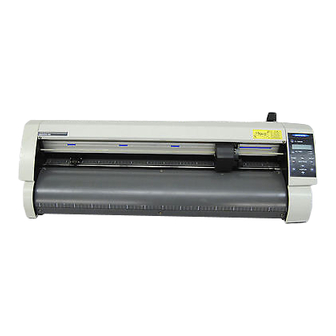
1.1 Overview The CE2000-60/120 is a cutting plotter that was developed for the specific purpose of cutting color adhesive-backed film. It is equipped with various functions that aim at improving the cutting quality. To ensure good cutting quality and optimum productivity, be sure to read this User’s Manual thoroughly before use. -
Page 15: Assembling Your Plotter (Ce2000-120)
1.3 Assembling Your Plotter (CE2000-120) Before You Begin Assembly (When Using the Basket) If you will be mounting the optional basket, assemble the basket after you have completed Step (1) in the section entitled “Assembling the Stand.” (1) Mount the center bar ( ) onto the R side foot ( ) and L side foot ( NOTE: At such time, loosely fasten the hexagon bolts. - Page 16 (3) After passing each roll shaft ( ) through a stopper ( ) and plastic hexagon screw ( ), mount each roll shaft as shown in the figure above to complete the assembly procedure. E-Ring 1 – 4...
-
Page 17: Names Of The Main Parts
NAMES OF THE MAIN PARTS 2.1 Front View ..................2-2 2.2 Rear View ..................2-3 2.3 Control Panel ................2-4... -
Page 18: Front View
Serial connector : Used to connect an RS-232C serial interface cable. Pen carriage : Moves pen left & right. Stand : The main unit is placed on this stand (a stand is optional for the CE2000-60 model). 2 – 2... -
Page 19: Rear View
2.2 Rear View CE2000-60 Power switch Roll media tray Roll media tray guide rail AC power inlet Roll media tray : Holds a roll medium for feeding to the cutting plotter. Roll media tray guide rail : Used to mount the roll media tray. -
Page 20: Control Panel
2.3 Control Panel Lamps : Remains lit while the cutting plotter is being POWER supplied with power. F1 / ORIGIN : Lights upon the receipt of plot data speci- PROMPT fying a coordinate point outside of the ef- fective plotting area. Panel Keys POWER F2 / TEST... -
Page 21: Setting Up The Cutting Plotter
SETTING UP THE CUTTING PLOTTER 3.1 Connecting to Your Computer ..........3-2 3.2 Turning on the Power ............. 3-3 3.3 Loading the Medium ..............3-4 3.3.1 Loading a Roll Medium ............3-4 3.3.2 Loading Single Sheets ............3-8 3.4 Selecting the COMMAND Mode and INTERFACE Conditions .................. -
Page 22: Connecting To Your Computer
Use either a Centronics-compatible parallel interface cable or a serial interface cable. Obtain a Graphtec- authorized interface cable that is compatible with your computer and can be connected to either the computer’s printer or serial port. -
Page 23: Turning On The Power
3.2 Turning on the Power Step Check that the Power switch is turned off (its “O” side is down). Step Connect the female plug of the power cord pro- vided to the cutting plotter’s AC power inlet and connect its male plug to an electrical socket. Be sure to ground the cutting plotter. -
Page 24: Loading The Medium
3.3 Loading the Medium The cutting plotter can use film in rolls or in single sheets. Loading the desired medium by following the pertinent instructions. 3.3.1 Loading a Roll Medium CE2000-60 Step Lower the media set lever to raise the push rollers. - Page 25 Step Adjust the position of the right and left push rollers to suit the width of the medium. Position each push roller at its corresponding edge of the medium so that it is above the grit roller. Move the push rollers so that they are po- sitioned inside the push roller align- ment marks provided.
- Page 26 CE2000-120 Step Lower the media set lever to raise the push rollers. Step Trap the medium’s edges between the two stoppers and then firmly fix each stopper in place by tightening its plastic hexagon screw. Gently pull the leading edge of the film toward you to remove any slack in the film as it is fed along the conveyance path from the main unit.
- Page 27 Step Adjust the position of the right and left push rollers to suit the width of the medium. Position each push roller at its corresponding edge of the medium so that it is above the grit roller. Move the push rollers so that they are positioned inside the push roller alignment marks provided.
-
Page 28: Loading Single Sheets
Chapter 4, “PREPARING FOR A CUTTING OPERATION”), the cutting plotter is ready to perform cutting so send cutting data from your application software at the computer. 3.3.2 Loading Single Sheets CE2000-60 Step Step Lower the media set lever to raise the push rollers. - Page 29 Step Step If the cutting plotter has already been turned on After the medium size has been detected, the cutting when the push rollers are lowered by raising the plotter awaits cutting data. media set lever, a menu for selecting the media If the INTERFACE conditions and COMMAND mode mode appears.
- Page 30 Position the push roller (2) so that it is at the midpoint of the film and is also over the center grit roller. The film is held in place using the three rollers called push rollers (1), (2), and (3). Push roller (3) Push roller Push roller(1)
-
Page 31: Selecting The Command Mode And Interface Conditions
Before sending data from the computer, you must set up the cutting plotter so that it can recognize the format (command mode) of data sent by the application software. The cutting plotter can recognize two data formats (command modes): Graphtec commands (GP-GL) or HP-GL. Select the COMMAND mode to suit your application. -
Page 32: Selecting The Step Size Or Origin Point
3.4.2 Selecting the STEP SIZE or ORIGIN POINT The STEP SIZE Setting The STEP SIZE setting is only required when the COMMAND setting is GP-GL. In GP-GL command mode, it is possible to change the minimum unit of distance which the cutter pen or pen can travel to one of four settings: 0.01, 0.025, 0.05, or 0.1 mm. -
Page 33: Selecting The Interface Conditions
3.4.3 Selecting the Interface Conditions It is necessary to select the INTERFACE conditions if you are using the RS-232C serial interface. INTERFACE settings include the data transfer rate (baud rate), data length, parity mode, and handshaking mode. The INTERFACE conditions you select for the cutting plotter must match those of the computer’s operating system. -
Page 34: Preparing For A Cutting Operation
PREPARING FOR A CUTTING OPERATION 4.1 Types and Features of Cutter Blades ......4-2 4.2 Replacing the Cutter Blade and Adjusting Its Length ..............4-2 4.3 Mounting the Cutter Pen Plunger ........4-5 4.4 Setting the Cutting Conditions ........... 4-6 4.4.1 Selecting a Set of Cutting Conditions ...... -
Page 35: Types And Features Of Cutter Blades
Before you start cutting, it is important that you become familiar with the types and features of the cutter blades which can be used with the cutting plotter. By selecting the optimum combination of cutter blade and film, you can achieve higher cutting quality. CAUTION To avoid cutting your fingers, always handle the cutter blade with caution. - Page 36 Replacing the Cutter Blade Step Turn the blade length adjustment knob Blade length Blade length adjustment knob (red) adjustment knob (blue) to retract the blade inside the plunger. Plunger for Plunger for 1.5-mm dia. blades 0.9-mm dia. blades 1.5-mm diameter 0.9-mm Spring cutter blade...
- Page 37 Adjusting the Blade Length CAUTION • To avoid cutting your fingers, always handle the cutter blade with caution. • If the blade is extended too far in relation to the thickness of the film being cut, it will damage the cutting mat. Be sure to properly adjust the blade length. Step Adjust the blade length by turning the blade length adjustment knob as shown in the figure below.
-
Page 38: Mounting The Cutter Pen Plunger
4.3 Mounting the Cutter Pen Plunger After the blade length has been properly adjusted, mount the cutter pen plunger in the cutting plotter as described below. Step Loosen the pen holder’s screw and then mount the cutter pen plunger Be sure to press the into the pen holder. -
Page 39: Setting The Cutting Conditions
4.4 Setting the Cutting Conditions Before starting a cutting operation, set the BLADE TYPE, FORCE, SPEED, CUTTER OFFSET, and QUALITY settings to provide the optimum cutting conditions. The compatibility of the selected cutting conditions with the film to be cut is determined by the five factors below. -
Page 40: Selecting A Set Of Cutting Conditions
Reference Pen Conditions for Plotting Pens Pen type FORCE SPEED QUALITY Water based fiber-tip pen 10 to 12 To preserve the pen’s longevity, set the FORCE to the lowest possible setting that permits you to obtain the desired plotted results. Set the SPEED after checking the plotted results for the absence of faint lines and other problems. -
Page 41: Specifying The Cutting Force
At the above menu, use the keys to change the PEN FORCE value. (The PEN FORCE can be set in a range from 1 to 31 for the CE2000-60, and from 1 to 39 for the CE2000-120.) ENTER When the displayed PEN FORCE value is satisfactory, press the key to register your setting. -
Page 42: Specifying The Cutting Speed
4.4.3 Specifying the Cutting SPEED This setting determines the speed with which cutting is performed. Set the SPEED value to suit the medium you will be using, based on the guidelines in the table entitled “Optimum Cutting Conditions According to Film Type” on page 4-6. Step After selecting the desired set of cutting conditions, check that the cutting plotter is in READY or PAUSE F2/TEST... -
Page 43: Specifying The Cutter Offset
4.4.4 Specifying the CUTTER OFFSET This setting adjusts the offset of the cutter blade according to the currently selected blade type. If the blade type is set to PEN, a plotting pen can be used. When a cutter blade designation or OTHER is selected, a cutter pen can be used. -
Page 44: Specifying The Cutting Quality
Press the key to display the menu below. NEXT PAGE CUTTER OFFSET QUALITY Step CE2000-60 Press the F2/TEST key (QUALITY) to display the menu below. QUALITY At the above menu, use the key to switch the QUALITY setting between 1 and 2. -
Page 45: Running A Cutting Test
4.5 Running a Cutting TEST After selecting the blade type and specifying the FORCE, SPEED, CUTTER OFFSET, and QUALITY settings, run a cutting test to ensure that the selected cutting conditions actually produce the desired cutting results by checking how far the blade cuts into the film and how corners are being cut. If the cut results are not satisfactory, repeatedly specify the cutting conditions and then run the cutting test until you achieve the optimum settings. -
Page 46: Using The Basic Functions
USING THE BASIC FUNCTIONS 5.1 Moving the Initial Cutting Position (Origin Point) ..5-2 5.2 Moving the Pen Carriage in +100-mm Steps ....5-3 5.3 Clearing Data from the Internal Memory ....... 5-3 5.4 Raising and Lowering the Pen ........... 5-4 5.5 Feeding the Medium .............. -
Page 47: Moving The Initial Cutting Position (Origin Point)
5.1 Moving the Initial Cutting Position (Origin Point) This function allows you to move the starting position for cutting or plotting to the desired position. New origin Original origin Step Step Use the POSITION keys to move the cutter pen Press the key. -
Page 48: Moving The Pen Carriage In +100-Mm Steps
5.2 Moving the Pen Carriage in +100-mm Steps This function lets you move the pen carriage from its current position in +100-mm steps along the X and Y axes. To Move the Pen Carriage ENTER While the READY or PAUSE menu is being displayed, hold down the key while you press the key. -
Page 49: Raising And Lowering The Pen
5.4 Raising and Lowering the Pen Use this function to raise or lower the pen. Step PAUSE Press the key to enter PAUSE status. Step Press the key until the menu below appears. NEXT PAGE INTERFACE PEN UP/DOWN F2/TEST F2/TEST At this menu, press the key once to lower the pen. -
Page 50: Feeding The Medium
5.5 Feeding the Medium When using cutting film, the FEED function advances the film and leaves faint tracks of the grit rollers on the film to prevent the film from being dislocated while it is being fed during actual cutting. Step PAUSE Press the... -
Page 51: Selecting The Length Unit
5.6 Selecting the LENGTH UNIT Use this function to select either mm or inch as the LENGTH UNIT. Step PAUSE Press the key to enter PAUSE mode. Step Press the key until the menu below appears. NEXT PAGE INTERFACE PEN UP/DOWN Step ENTER Simultaneously press the... -
Page 52: Using Applied Functions
USING APPLIED FUNCTIONS 6.1 Rotating the Coordinate Axes ..........6-2 6.2 Using the COPY Function ............. 6-3 6.3 Enabling the AUTO PRE FEED Mode ......6-5 6.4 Adjusting the Distance Precision ........6-6 6.5 Aligning the Coordinate Axes ..........6-7 6.6 Specifying the Page Length .......... -
Page 53: Rotating The Coordinate Axes
6.1 Rotating the Coordinate Axes The ROTATE function allows you to rotate the initial cutting point and the coordinate system as shown in the figure below. The ROTATE setting is retained in the cutting plotter’s internal memory, even while the cutting plotter is turned off. When the ROTATE setting is ON When the ROTATE setting is OFF Step... -
Page 54: Using The Copy Function
6.2 Using the COPY Function Use the COPY function to make duplicate copies of cutting data that has been sent from the computer and retained in the cutting plotter’s internal memory. 3rd copy 6th copy 2nd copy 5th copy 1st copy 4th copy COPY operation’s origin Initial cutting operation’s origin... - Page 55 Step Use the keys to specify the number of copies you wish to make. Step When the desired value is displayed, press the ENTER key to initiate the COPY operation to make the specified number of copies. Step If you wish to continue making copies, replace the film with new film and then repeat Steps 2 through NOTE : •...
-
Page 56: Enabling The Auto Pre Feed Mode
6.3 Enabling the AUTO PRE FEED Mode When the CE2000 first receives data while the AUTO PRE FEED setting is ON, it automatically feeds the medium forward and backward by the specified distance. This operation marks the cutting film with the tracks of the grit rollers and thus prevents the film from slipping out of place. When using roll film, moreover, the CE2000 automatically advances the leading edge of the medium. -
Page 57: Adjusting The Distance Precision
6.4 Adjusting the Distance Precision The DIST ADJ. function can be used to correct any deviation in the length of cut or plotted line segments which occurs as a result of the medium being used. The corrective value for any deviation in each coordinate axis is specified as a percentage of the total distance. -
Page 58: Aligning The Coordinate Axes
6.5 Aligning the Coordinate Axes When loading new film, the AXIS ADJ. function is used to reposition the coordinate axes to compensate for any deviation in the coordinate axes and origin between the cutting plotter and the medium which has previously been cut or plotted. This function lets you re-align the cutting plotter’s coordinate axes to match those of a previously cut or plotted medium. - Page 59 Step ADJ. PT 2 Use the POSITION keys to move the cutter pen to the desired ADJ. PT 2 position (any position along the X axis of the initially plotted figure). The coordinate values displayed at such time represent the relative distances from the ADJ.
-
Page 60: Specifying The
6.6 Specifying the Page Length This function lets you specify the length of each page. When using a roll medium, the PAGE LENGTH setting corresponds to the length per page. Before performing long-axis cutting of an image longer than two meters, be sure to specify the PAGE LENGTH setting. Step PAUSE Press the... -
Page 61: Specifying The Plot Area
6.7 Specifying the PLOT AREA This function allows you to specify the area in which cutting will be performed, thus preventing cutting outside of the specified area. This function lets you make more efficient use of film. When you wish to cut an uncut portion of film that has already been cut, specify the PLOT AREA to exclude the previously cut area. - Page 62 Step Use the POSITION keys to move the carriage to the lower left corner of the desired cutting area. When ENTER the carriage is satisfactorily positioned, press the key. If you wish to use the default L.L. setting (0,0) instead of specifying a new L.L. position, however, ENTER press the key (DEFAULT) before pressing the...
-
Page 63: Expanding The Width Of The Plot Area
6.8 Expanding the Width of the Plot Area The EXPAND function allows you to extend the width of the plot area by 9.5 mm on both sides for a total 19-mm increase, thereby enabling you to perform cutting up to the area where the pinch rollers are positioned. -
Page 64: Using The Extended Functions
USING THE EXTENDED FUNCTIONS 7.1 Specifying the PEN UP SPEED .......... 7-2 7.2 Specifying the OFFSET FORCE ......... 7-3 7.3 Specifying the OFFSET ANGLE ......... 7-4 7.4 Selecting the STEP PASS ............. 7-5... -
Page 65: Specifying The Pen Up Speed
7.1 Specifying the PEN UP SPEED This function is used to specify the travelling speed of the cutter pen in raised status. It can be specified independently of the cutting SPEED function. When the PEN UP SPEED is high, the cutter pen travels faster while in raised status to shorten the overall cutting time. -
Page 66: Specifying The Offset Force
OFFSET FORCE and then press the key to register your setting. The OFFSET FORCE can be set in a range of 1 to 31 for the CE2000-60, and 1 to 39 for the CE2000- 120. Step... -
Page 67: Specifying The Offset Angle
7.3 Specifying the OFFSET ANGLE Based on the coordinate data received, the cutting plotter controls the angle of the cutter blade’s tip according to the displacement of the travelling angle as defined by the data which specifies the movement of the cutter pen between coordinate points. This function sets the reference value used for adjusting the cutter blade’s offset angle. -
Page 68: Selecting The Step Pass
7.4 Selecting the STEP PASS Use this function when the coordinate data received specifies extremely short line segments. The cutting plotter uses the specified STEP PASS setting as the unit for blade tip control, omitting blade tip control for any data that is below the STEP PASS setting. This results in higher image quality by permitting smooth blade tip control when cutting circles, arcs, and other curved lines. -
Page 69: Using The Special Functions
USING THE SPECIAL FUNCTIONS 8.1 Description of the Special Functions ......8-2 8.2 Specifying the Special Functions ........8-4... -
Page 70: Description Of The Special Functions
8.1 Description of the Special Functions The cutting plotter is also provided with the special functions described below. These functions are specified only for special situations and are not used for normal cutting operations. (1) Enabling/Disabling the “:”, “,”, and “;” Commands (When the COMMAND setting is GP-GL) When the COMMAND setting is GP-GL, this function is set to determine whether the cutting plotter will recognize or ignore the receipt of “:”, “,”, and “;”... - Page 71 (6) Enabling/Disabling Consecutive Pen Travel in Raised Status (PEN UP MOVE) In response to the receipt of consecutive commands specifying pen movement in raised status, this function determines whether the pen will travel to each point specified or only from the initially specified point to the last specified point.
-
Page 72: Specifying The Special Functions
8.2 Specifying the Special Functions Step Step While holding down the key, turn on the cutting Depending on the current COMMAND setting (GP- plotter. The menus for setting the special functions GL or HP-GL), press the key to cycle through NEXT PAGE will appear at the display panel. -
Page 73: Troubleshooting Procedures
TROUBLESHOOTING PROCEDURES 9.1 Printing a List of the Currently Selected Conditions ... 9-2 9.2 Running a SELF TEST ............9-4 9.3 Using the DUMP Mode ............9-5 9.4 Cutting the Demo Pattern ............. 9-7 9.5 The Plotter is Turned On But Doesn’t Operate .. -
Page 74: Printing A List Of The Currently Selected Conditions
9.1 Printing a List of the Currently Selected Conditions Use this function to print out a list of the cutting plotter's currently selected conditions. A sample printout is shown on the next page. Step Mount a plotting pen (not a cutter pen) at the cutting plotter's pen holder and then set the pen type, FORCE, SPEED, and QUALITY to suit the pen mounted. - Page 75 CE2000-120 CONDITIONS CONDITION FORCE SPEED PEN TYPE OFFSET ACCEL ∗ 1 OTHER RS-232C BAUD RATE PARITY DATA BIT HANDSHAKE 9600 COMMAND HP-GL STEP SIZE 0.025 HP-GL ORIGIN L.L. PAGE LENGTH 2000 PEN UP SPEED AUTO STEP PASS OFFSET FORCE OFFSET ANGLE ROTATE DISPLAY UNIT EXPAND...
-
Page 76: Running A Self Test
9.2 Running a SELF TEST The SELF TEST function prints out a test pattern for checking the precision of the operation of the cutting plotter itself (but not the status of its connection to a computer). Step Mount a plotting pen (not a cutter pen) at the cutting plotter's pen holder and then set the pen type, FORCE, SPEED, and QUALITY to suit the pen mounted. -
Page 77: Using The Dump Mode
9.3 Using the DUMP Mode In contrast with the SELF TEST mode which checks the operation of the cutting plotter itself, this function prints the data received by the cutting plotter from the computer as codes so you can check whether data transfer is being properly conducted. - Page 78 Step When the key (ON) is pressed, the "DUMP MODE" message is displayed, so send data F1/ORIGIN to the cutting plotter from the computer in this status. Upon receiving the data, the cutting plotter will begin printing it as codes. Step To cancel DUMP mode, turn the cutting plotter off then back on again.
-
Page 79: Cutting The Demo Pattern
9.4 Cutting the Demo Pattern Use this function to cut a demonstration pattern. Step Mount a cutter pen at the cutting plotter's pen holder and then set the blade type, FORCE, SPEED, QUALITY, and CUTTER OFFSET to suit the cutter blade mounted. Step Step ENTER... -
Page 80: The Plotter Is Turned On But Doesn't Operate
AC line inlet and the electrical output. The POWER lamp lights but nothing ap- The plotter is defective. Contact your sales represen- pears on the display panel. tative or nearest Graphtec dealer. 9.6 Mechanical Error Messages and Their Causes Error message Cause Solution... -
Page 81: Command Error Messages And Their Causes
9.7 Command Error Messages and Their Causes If any of the following command errors occur, they are nearly always caused by one of the reasons below: (1) The software configuration regarding the output device has been changed: or (2) The plotter’s interface conditions have been changed. When a command error occurs, therefore, first check the three corresponding points below: (1) Configure the application software so that it can control the cutting plotter. - Page 82 Error messages in GP-GL command mode (2/2) Error message Cause Solution A command was received with an ERROR 3 incorrectly specified delimiter. DELIMITER ERROR → Configure the software to • The software configuration regard- drive your plotter. ing the output device has been Ensure that the software’s changed.
- Page 83 Error messages in HP-GL emulation mode Error message Cause Solution An unrecognizable instruction was Execute a recognizable com- ERROR 1 executed. mand. INSTRUCTION ERR A command was executed with the Execute the command with the ERROR 2 wrong number of parameters. correct number of parameters.
-
Page 84: The Cutting Results Are Unsatisfactory
9.8 The Cutting Results are Unsatisfactory Problem Cause Solution • • The cut corners are rounded The CUTTER OFFSET is incom- • Adjust the CUTTER OFFSET value: or too pointed. patible with the blade type being - If too low, corners become rounded. used. - Page 85 Problem Cause Solution • Abnormal noise generate by • Film is stuck in the tip of the cutter • Adjust the blade length and cutting the cutter pen during cutting. plunger. FORCE setting. • The film is discolored where the blade has passed. •...
- Page 86 Problem Cause Solution • Film is loaded but the • Film that is nearly transparent • Disable the paper sensors by tur ning RELOAD PAPER ! prompt cannot be detected by the paper off the Maintenance 1 function, then appears. sensors.
- Page 87 APPENDIX APPENDIX A.1 Main Specifications ..............A-2 A.2 Options and Supplies ............. A-3 A.3 External Dimensions ..............A-4 A.4 Menu Tree ..................A-6...
-
Page 88: Main Specifications
External dimensions (including stand) Weight 13 kg 46 kg (including stand) Varies with the type of Graphtec-authorized film and the cutting conditions. HP-GL is a registered trademark of Hewlett-Packard Company. Only in the diagonal (45° angle) direction. A – 2... -
Page 89: Options And Supplies
A.2 Options and Supplies To place orders or request more information about the options and supplies available for your cutting plotter, please contact your sales representative or nearest Graphtec vendor. Options Designation Part no. Description Stand ST0033 Dedicated stand for the CE2000-60... -
Page 90: External Dimensions
A.3 External Dimensions CE2000-60 851mm (280mm) 278mm Dimensional precision: ± 5 mm error CE2000-120 1489 1333 A – 4... - Page 91 CE2000-120 with optional basket 1494 1333 A – 5...
-
Page 92: Menu Tree
A.4 Menu Tree COND1 COND1 09U 0 14 09U 0 14 TEST CUT TEST CUT –– ––PAUSE PAUSE–– –– PEN SETTINGS PEN SETTINGS SPEED SPEED SPEED SPEED PEN FORCE PEN FORCE 30 cm/s 30 cm/s PEN FORCE PEN FORCE NEXT NEXT CUTTER OFFSET CUTTER OFFSET... -
Page 93: Index
INDEX AC power inlet ..........2-3 Data length ........... 3-13 Aligning the coordinate axes ......6-7 Data transfer rate ........3-13 AUTO PRE FEED mode ......6-5 Demo pattern, cutting the ......9-7 AXIS ADJ. function ........6-7 DIST ADJ. function ........6-6 Distance precision, adjusting the .... - Page 94 QUALITY, cutting ......... 4-6, 4-11 Media sensors ..........3-4 Setting procedure ......... 4-11 Enabling/disabling the ......8-3 Medium set lever ........... 2-2 Media tray ............2-3 Roll medium, loading a ......... 3-4 Media tray guide rail ........2-3 ROTATE function .......... 6-2 Menus, flowchart of ........
Need help?
Do you have a question about the CE2000-60 and is the answer not in the manual?
Questions and answers
Want carriage belt