
Related Manuals for GRAPHTEC CE5000 Series


Summary of Contents for GRAPHTEC CE5000 Series
- Page 1 CE5000 Series CUTTING PLOTTER SERVICE MANUAL MANUAL NO. CE5000-UM-251 CE5000-UM-251-22-9370...
- Page 2 HISTORY OF REVISIONS No. Date issued Description of revision Page Edition 06.07.06 First Printing 06.09.13 Information for the 9e60p was added. 10-1,10-12 06.09.13 Part list for the steel stand ST0068 was added. 10-9 06.09.13 Part number for the main board of the CE5000-40 was corrected. 4-1,10-1 06.09.26 Procedure of upgrading the system firmware was corrected.
- Page 3 13.02.20 Part number for the Drive Roller 120 was corrected. 4-1,10-5 13.02.20 Part number for the Drive Roller 60 was corrected. 4-1,10-3 13.02.20 Part number for the Drive Roller 40 was corrected. 4-1,10-3 13.02.20 Part number for the Left Side Cover was corrected. 10-1 13.02.20 Part number for the Front Guide 60 was corrected.
-
Page 4: Table Of Contents
CONTENTS INTRODUCTION .................1-1 Main Specifications .......................1-1 1.2 External Dimensions ......................1-3 PARTS NAMES and FUNCTIONS ..........2-1 Parts Names and Functions ....................2-1 2.2 Assembling the Stand ......................2-5 2.3 Attaching the Basket (CE5000-60/120: Optional) ..............2-12 OPERATIONS ................3-1 Control Panel ......................... 3-1 3.2 Menu List .......................... - Page 5 6.2.2 How to Replace the Push Roller ......................6-11 6.2.3 How to Replace the Push Roller Arm ....................6-12 6.2.4 How to Replace the Cam Sensor Board ....................6-14 6.2.5 How to Replace the Pen Block ......................6-15 6.2.6 How to Replace the Push Roller Sensor ....................6-17 6.2.7 How to Replace the Y-relay Board ......................6-18 6.2.8 How to Replace the Cutting Mat ......................6-19 6.2.9 How to Replace the Control Panel Relay Board, LCD and Membrane Switch Panel ......
- Page 6 7.13 Adjusting the Pen Exchange Height Value (CE5000-120AP) ........7-18 7.14 Adjusting the Spacing Between Pen 1 and Pen 2 (CE5000-120AP) ...........7-19 SERVICE MODES ..............8-1 Sensor Test Mode ......................... 8-1 8.2 Control Panel Membrane Switch Test Mode ............... 8-2 8.3 Clear Setup Mode ........................
- Page 7 11.2.7 Main Board Memory Block Section (PN5043-01A) ................11-9 11.2.8 Relay and Sensor Board Section ......................11-10 11.2.9 Control Panel Membrane Switch Panel Section ................11-11 11.2.10 120-Relay Board Section ........................11-12 11.2.11 120-Pen Encoder Flexible Cable Section (PN5043-10) ..............11-12 11.2.12 Main Board CPU Section (PN0021-01) ....................11-13 11.2.13 Main Board Connector Section (PN0021-01) ..................
-
Page 9: Introduction
1,487 x 744 x 1194 mm Weight Approx. 9.4 kg Approx. 25 kg Approx. 39.1 kg *1: Varies depending on the type of Graphtec-authorized film and the cutting conditions *2: HP-GL is a registered trademark of Hewlett-Packard Company. *3: Including the stand CE5000-UM-251-9370... - Page 10 0.1 mm/°C, 0.3 mm/10% RH. *2: The precision specification is the precision that was obtained when Graphtec’s mylar film was used to measure the mechanical precision. Please note that as only fine quality pattern paper can be used with this device, the precision may differ slightly.
-
Page 11: External Dimensions
INTRODUCTION External Dimensions CE5000-40CRP Units: mm Dimensional accuracy: ±5 mm CE5000-60 Units: mm Dimensional accuracy: ±5 mm CE5000-UM-251-9370... - Page 12 INTRODUCTION CE5000-120 1487 Units: mm Dimensional accuracy: ±5 mm CE5000-120AP 1487 1020 Units: mm Dimensional accuracy: ±5 mm CE5000-UM-251-9370...
-
Page 13: Parts Names And Functions
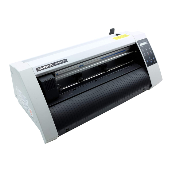
PARTS NAMES and FUNCTIONS 2 PARTS NAMES and FUNCTIONS Parts Names and Functions Front View Cutting mat Pen carriage Grit roller Pen holder Media set lever Control panel Push rollers Serial (RS-232C) interface connector USB interface connector The above illustration is of the CE5000-120 model. Cutting mat : Cutting or plotting is performed on this mat. - Page 14 PARTS NAMES and FUNCTIONS Rear View Power switch AC power inlet Stock rollers Stoppers Stand The above illustration is of the CE5000-120 model. AC power inlet : Connects the power cord to the cutting plotter Power switch : Turns the power supply to the cutting plotter on or off Stand : Supports the cutting-plotter unit Stock rollers...
- Page 15 PARTS NAMES and FUNCTIONS Front View (CE5000-120AP) Cutter pen holder Pen holder Pen station Cutting mat Control panel Grit roller Pen carriage Media set lever Serial (RS-232C) interface connector interface connector Stopper Stock shaft Push rollers Cutting mat : Cutting or plotting is performed on this mat. Grit roller : Feeds the medium backward or forward.
- Page 16 PARTS NAMES and FUNCTIONS Rear View (CE5000-120AP) Power switch AC power inlet Stand Basket Alignment shaft AC power inlet : Connects the power cord to the cutting plotter. Power switch : Turns the power supply to the cutting plotter on or off. Stand : Supports the cutting-plotter unit.
-
Page 17: Assembling The Stand
PARTS NAMES and FUNCTIONS Assembling the Stand CE5000-60/120:Standard Stand Construction The stand is made up of the following parts. Stand feet (L/R) Stand side bar(L/R) Center bar CE5000-60 CE5000-60 CE5000-120 CE5000-60 CE5000-120 CE5000-120 Hexagonal socket bolt Hexagonal socket bolt Coin screw x 4 Allen wrench (M5) Allen wrench (M6) (M6) x 8... - Page 18 PARTS NAMES and FUNCTIONS (3) Loosely fasten the stand side bars (L/R) to the center bar with the hexagonal socket bolts (CE5000-60: M5, CE5000-120: M6), using the Allen wrench. CE5000-60 Center bar Center bar Hexagonal socket bolt (M6) Stand side bar Stand side bar Hexagonal socket bolt...
- Page 19 PARTS NAMES and FUNCTIONS CE5000-120AP:Standard Stand Construction The stand is made up of the following parts. Stand side bar x 2 (L/R) Center bar x 1 Hexagonal socket bolt (M6) x 8 Allen wrench (M6) x 1 Stopper x 2 (L/R) Alignment shaft x 1 Stock shaft x 1 Basket Construction...
- Page 20 PARTS NAMES and FUNCTIONS Stand Assembly Instructions (1) Fasten the center bar to the stand side bars (L/R) temporarily with the hexagonal socket bolts (M6), using the Allen wrench. Front side Center bar Stand side bar Hexagonal socket bolt (M6) (2) Fasten the sheet support pipe brackets to the stand tops with the hexagonal socket bolts (M6).
- Page 21 PARTS NAMES and FUNCTIONS (3) Insert the sheet support pipes into the sheet support pipe brackets. Use the lower holes for the pipe that will be at the front of the cutting plotter, and the upper holes for the pipe that will be at the rear. Remove the tape from the ends of the pipes to expose the adhesive, and then fit the rubber caps on firmly.
- Page 22 PARTS NAMES and FUNCTIONS (5) Attach the media guide bracket to the underside of the front panel. Loosen the two decorative screws that are attached to the underside of the front panel (one on each side) by two or three turns, slot the bracket in, and then tighten the screws.
- Page 23 PARTS NAMES and FUNCTIONS (8) Pull out the sheet support pipes, and attach the sheet to them. Pass the sheet over the center bar, and fasten the ends to the support pipes using the press-studs. Sheet support pipe Pass over the center bar Press-stud Side view Sheet...
-
Page 24: Attaching The Basket (Ce5000-60/120: Optional)
PARTS NAMES and FUNCTIONS Attaching the Basket (CE5000-60/120: Optional) Basket Construction The basket is made up of the following parts. Sheet support pipe Sheet Hexagonal socket bolts (M6) x 4 Basket Assembly Instructions (1) Detach the four coin screws or hexagonal socket bolts (M6), and separate the cutting plotter from the stand. - Page 25 PARTS NAMES and FUNCTIONS (3) Mount the CE5000 cutting plotter on the stand by inserting the positioning pins on the stand into the positioning holes on the underside of the cutting plotter. Fasten using the four coin screws or hexagonal socket bolts (M6).
-
Page 27: Operations
OPERATIONS 3 OPERATIONS Control Panel Indicator Lamp STATUS �����Illuminates while the power to the cutting plotter is turned on, and goes out when the cutting plotter is in PAUSE status� This lamp flashes when data is being received from an interface, regardless of whether or not the cutting plotter is in PAUSE status�... -
Page 28: Menu List
OPERATIONS Menu List Pressing the (PAUSE) key in READY mode displays the PAUSE menu, enabling the various settings to be made� Select the required menu by scrolling through the list using the (NEXT) and (PREV�) keys� CE5000-40CRP M O V E T O R . M A R K F E E D A U T O P R E F E E D M A R K M O D E... - Page 29 OPERATIONS CE5000-60/120 M O V E T O R . M A R K F E E D The Registration Mark Sensor function is an option. A U T O P R E F E E D M A R K M O D E T A N G E N T I A L M A R K P O S I T I O N A U T O R E G .
- Page 30 OPERATIONS CE5000-120AP C L E A R B U F F E R F E E D & C U T B L A D E W A R E S E T U P P E N U P / D O W N C U T L I N E P A T .
-
Page 31: Description Of Special Functions A
OPERATIONS Description of Special Functions A The cutting plotter is provided with the special functions described below. These functions are specified only in special situations, and are not normally used� (1) Turn on the cutting plotter while holding down the key�... - Page 32 OPERATIONS • Enabling/Disabling the “:” and “;” Commands (when the COMMAND setting is GP-GL) This function enables or disables the “:” and “;” commands when the COMMAND setting is GP-GL� If the first part of the data is lost, these commands may be having an adverse effect. In this case, set this function to DISABLED (the default setting is ENABLED)�...
- Page 33 OPERATIONS • Enabling/Disabling PEN UP MOVE This function sets whether the pen will travel to each point specified or only from the initially specified point to the last specified point when consecutive commands are received specifying pen movement while it is raised� When ON is selected, the pen travels consecutively to each coordinate specified by the data received.
-
Page 34: Description Of Special Functions B
OPERATIONS Description of Special Functions B These functions are specified only in the special situations described below, and are not normally used. • Display Language Setting (MENU LANGUAGE SELECTION) This function sets the language used on the display� One of six languages can be selected: English, French, German, Italian, Spanish, or Japanese�... -
Page 35: Recommended Parts List
RECOMMENDED PARTS LIST 4 RECOMMENDED PARTS LIST Part No. Description -120 -120AP Remarks Rank 621352000 Push Roller 621360021 Cutting Mat 40 – – – 621350041 Cutting Mat 60 – – – 621351051 Cutting Mat 120 – – – 621250520 Cutting Mat 120AP –... -
Page 37: List Of Tools
LIST OF TOOLS 5 LIST OF TOOLS Tools Adjustment Item Tool 1 Pen force adjustment Cutter pen holder (CB09) Correx Dial Tension gauge (50,300,500 gf) 2 Distance adjustment Glass scale 3 Pen block height adjustment 10 mm height block 4 Firmware update PC, USB I/F cable 5 X-drive belt tension adjustment Push-pull gauge (2 kg) -
Page 39: Disassembly And Reassembly
DISASSEMBLY AND REASSEMBLY 6 DISASSEMBLY AND REASSEMBLY Exterior Parts 6.1.1 How to Replace the Right Side Cover How to detach the right side cover (1) Remove the three M4L6 binding head screws from the right side cover. Note: Hold the right side cover after you have detached the screws; there is a flexible cable inside the cover. (2) Disconnect the flexible cable which is connected to the control panel relay board. M3L6 TP head screw M4L6 binding head screw... -
Page 40: How To Replace The Center Cover (Ce5000-40/60)
DISASSEMBLY AND REASSEMBLY 6.1.3 How to Replace the Center Cover (CE5000-40/60) How to detach the center cover (1) Remove the two M3L6 TP head screws from the center cover. M3L6 TP head screw M4L6 binding head screw Center cover Left side cover Right side cover M4L6 binding head screw... -
Page 41: How To Replace The Center Cover (Ce5000-120/120Ap)
DISASSEMBLY AND REASSEMBLY 6.1.4 How to Replace the Center Cover (CE5000-120/120AP) How to detach the center cover (1) Remove the three M3L6 TP head screws from the center cover. M3L6 TP head screw Center cover Right side cover Left side cover How to reinstall the center cover (1) Mount the center cover and fasten the three M3L6 TP head screws. -
Page 42: How To Replace The Front Guide (Ce5000-40/60)
DISASSEMBLY AND REASSEMBLY 6.1.5 How to Replace the Front Guide (CE5000-40/60) How to detach the front guide (CE5000-60) (1) Remove the two M3L6 binding head screws from front guide 40. (2) Remove the M3L6 binding head screw from front guide 60. (3) Pull out the front guides to the front. -
Page 43: How To Replace The Front Guide (Ce5000-120/120Ap)
DISASSEMBLY AND REASSEMBLY 6.1.6 How to Replace the Front Guide (CE5000-120/120AP) There are two measuring tapes on the front guide of the CE5000-120. You have to attach new tapes after replacing the front guide. How to detach the front guide (CE5000-120/120AP) (1) Remove the three M3L6 TP head screws from front guide 120. (2) Pull out the front guide to the front. M3L6 TP head screw The top of the front guide is hooked onto these holders. - Page 44 DISASSEMBLY AND REASSEMBLY How to reinstall the front guide (CE5000-120) (1) Have ready two 250 mm-long measuring tapes when you replace the front guide. Front guide 120 Fold back a 30-mm length of tape at this edge. Make sure that a thick line is right on the edge. Affix approx. 205 mm of the tape here, and fold back the rest of the tape to the inside of the guide.
- Page 45 DISASSEMBLY AND REASSEMBLY (4) Install the front guide as shown below. M3L6 TP head screw Hook the front guide notches onto these holders. Front guide notch Front guide (5) Slide in front guide 120 and hook the notches onto the main frame as shown in the above figure. (6) Fasten the three M3L6 TP head screws. CE5000-UM-251-9370...
-
Page 46: How To Replace The Rear Guide
DISASSEMBLY AND REASSEMBLY 6.1.7 How to Replace the Rear Guide How to detach the rear guide (1) Remove the two M3L6 binding head screws from the rear guide. (Remove the three M3L6 binding head screws from the rear guide for the CE5000-120/120AP.) (2) Set the cam lever to the media hold position. - Page 47 DISASSEMBLY AND REASSEMBLY (2) Fasten the two M3L6 binding head screws. (Fasten the three M3L6 binding head screws for the CE5000-120/120AP.) CE5000-UM-251-9370...
-
Page 48: Mechanical Parts
DISASSEMBLY AND REASSEMBLY Mechanical Parts 6.2.1 How to Replace the Front and Rear Media Sensors How to detach the front or rear media sensor (1) Detach the front or rear guide (Front guide: see Subsection 6.1.5 for CE5000-40 and 60, and Subsection 6.1.6 for CE5000-120/120AP; Rear guide: see Subsection 6.1.7). (2) Remove the M3L12 binding head screw attaching the sensor. (3) Disconnect the sensor from the connector. -
Page 49: How To Replace The Push Roller
DISASSEMBLY AND REASSEMBLY 6.2.2 How to Replace the Push Roller How to detach the push roller (1) Detach the right side of the E-ring from the push roller shaft. Push roller arm Push roller Push roller shaft E-ring (2) Detach the push roller shaft from the push roller arm from the left side. (3) Detach the push roller. How to reinstall the push roller (1) Reattach the push roller in the reverse order in which it was detached. CE5000-UM-251-9370 6-11... -
Page 50: How To Replace The Push Roller Arm
DISASSEMBLY AND REASSEMBLY 6.2.3 How to Replace the Push Roller Arm How to detach the push roller arm (1) Detach the right and left side covers (see Subsection 6.1.1 and Subsection 6.1.2). (2) Detach the center cover (see Subsection 6.1.3 or 6.1.4). (3) Set the cam lever to the media release position. - Page 51 DISASSEMBLY AND REASSEMBLY (7) Detach the right side cam shaft holder. Right cam shaft holder Cam shaft (8) Pull out the cam shaft from the right side. (9) Detach the push roller arm spring from the push roller arm. (10) Detach the E-ring from the push roller arm shaft. Push roller arm shaft E-ring (11) Detach the push roller arm shaft from the push roller arm and detach the push roller arm, push roller arm base, and the cam. How to reinstall the push roller arm (1) Spread a suitable quantity of the Shinetu silicon grease G501 on the cam as shown below.
-
Page 52: How To Replace The Cam Sensor Board
DISASSEMBLY AND REASSEMBLY 6.2.4 How to Replace the Cam Sensor Board How to detach the cam sensor board (1) Detach the right side cover (see Subsection 6.1.1). (2) Disconnect the flexible cable from connector J701 on the cam sensor board. M3L6 binding head screw Cam sensor board (3) Remove the M3L6 binding head screw attaching the cam sensor board. How to reinstall the cam sensor board (1) Reattach the cam sensor board in the reverse order in which it was detached. -
Page 53: How To Replace The Pen Block
DISASSEMBLY AND REASSEMBLY 6.2.5 How to Replace the Pen Block How to detach the pen block (1) Detach the center cover (see Subsection 6.1.3 or 6.1.4). (2) Loosen the M3L6 binding head screw attaching the pen block cover. M3L6 binding screw J503 M2L5 binding screw Y-relay board J505 J504 Auto registration sensor bracket Pen block cover (3) Remove the pen block cover. - Page 54 DISASSEMBLY AND REASSEMBLY (6) Remove the two M4L6 binding head screws attaching the pen block. M4L6 binding head screw Pen block How to reinstall the pen block (1) Attach the pen block to the Y-slider. (2) Move the pen block to center of the Y bar and lower the pinch roller when measuring the pen block height. a gap of 10 mm (3) Fasten the two M4L6 binding head screws to attach the pen block so that there is (CE5000-120AP: 11.5 mm) between the bottom of the pen block and the cutting mat. Perform a visual check to make sure that the pen block is not mounted at an angle. Side view of the pen block Cutting mat CE5000-40/60/120: 10 mm CE5000-120AP: 11.5 mm (4) Reattach the other parts in the reverse order in which they were detached.
-
Page 55: How To Replace The Push Roller Sensor
DISASSEMBLY AND REASSEMBLY 6.2.6 How to Replace the Push Roller Sensor How to detach the push roller sensor (1) Detach the center cover (see Subsection 6.1.3 or 6.1.4). (2) Detach the pen block (see Subsection 6.2.5). (3) Disconnect the push roller sensor flexible cable from the Y-relay board. (4) Remove the push roller sensor flexible cable that is attached with double-sided adhesive tape to the Y-slider. (5) Remove the M3L6 binding head screw attaching the push roller sensor bracket to the slider. Y-slider M3L6 binding head screw Push roller sensor board Push roller sensor bracket... -
Page 56: How To Replace The Y-Relay Board
DISASSEMBLY AND REASSEMBLY 6.2.7 How to Replace the Y-relay Board How to detach the Y-relay board (1) Detach the center cover (see Subsection 6.1.3 or 6.1.4). (2) Detach the pen block cover (see Subsection 6.2.5). (3) Disconnect all the cables from the Y-relay board. To disconnect the Y-flexible cable: Remove the wiring harness tiewrap and detach the core attached with double-sided adhesive tape to the Y-relay board. (4) Remove the push roller sensor flexible cable attached with double-sided adhesive tape to the Y-slider. Y-flexible cable M3L6 binding head screw Core Y-relay board (5) Remove the two M3L6 binding head screws attaching the Y-relay board. -
Page 57: How To Replace The Cutting Mat
DISASSEMBLY AND REASSEMBLY 6.2.8 How to Replace the Cutting Mat How to detach the cutting mat (1) Detach the center cover (see Subsection 6.1.3 or 6.1.4). (2) Detach the front guide (see Subsection 6.1.5 or 6.1.6). (3) Detach the pen block (see Subsection 6.2.5). (4) Peel off the cutting mat from the vacuum base. Cutting mat Vacuum base How to reinstall the cutting mat... -
Page 58: How To Replace The Control Panel Relay Board, Lcd And Membrane Switch Panel
DISASSEMBLY AND REASSEMBLY 6.2.9 How to Replace the Control Panel Relay Board, LCD and Membrane Switch Panel How to detach the control panel relay board, LCD and membrane switch panel (1) Detach the right side cover (see Subsection 6.1.1). (2) Disconnect the flexible cables from connector J402 and J403 on the control panel relay board. (3) Remove the M3L8 self-tapping screw attaching the control panel relay board. - Page 59 DISASSEMBLY AND REASSEMBLY (8) Peel off the membrane switch panel from the right side cover. Membrane switch panel Right side cover How to reinstall the control panel relay board, LCD assembly and membrane switch panel (1) Clean the surface of the right side cover with alcohol where the membrane switch panel was attached. (2) Reattach the LCD assembly to the right side cover. (3) Attach the membrane switch panel to the right side cover so that it fits around the LCD window. (4) Reattach the other parts in the reverse order in which they were detached. CE5000-UM-251-9370 6-21...
-
Page 60: How To Replace The Y-Belt
DISASSEMBLY AND REASSEMBLY 6.2.10 How to Replace the Y-belt How to detach the Y-belt (1) Detach the right and left side covers (see Subsection 6.1.1 and Subsection 6.1.2). (2) Detach the center cover (see Subsection 6.1.3 or 6.1.4). (3) Detach the pen block (see Subsection 6.2.5). (4) Loosen the M3L6 TP head screw attaching the Y-tension arm. - Page 61 DISASSEMBLY AND REASSEMBLY How to reinstall the Y-belt (1) Shave 2 to 3 mm off both ends of the Y-belt until the wire comes out as shown below. Y-belt Shave 2 to 3 mm off both ends of the Y-belt until the wire comes out. (2) Hang the Y-belt on both sides of the pulley. (3) Attach both ends of the Y-belt to the Y-slider so that four notches of the Y-belt fit into the Y-slider, then attach with the Y-belt stopper plates removed in step (6) in the previous subsection. Y-belt M3L6 binding head screw Y-slider Y-belt stopper plate (4) Attach the pen block (see Subsection 6.2.5).
-
Page 62: How To Replace The Y-Motor
DISASSEMBLY AND REASSEMBLY 6.2.11 How to Replace the Y-motor How to detach the Y-motor (1) Detach the right side cover (see Subsection 6.1.1). (2) Detach the front guide (see Subsection 6.1.5 or6.1.6). (3) Disconnect the Y-motor cables from connector J8 and J11 on the main board. (4) Loosen the two M3L4WP set screws to detach the Y-motor pulley. M3L4WP set screw Y-motor drive belt M3L6 binding head screw Y-motor Y-motor pulley... - Page 63 DISASSEMBLY AND REASSEMBLY How to reinstall the Y-motor (1) Attach the pulley flange and the spacer to the new Y-motor. (2) Attach the Y-motor to the Y-motor bracket. (3) Hang the Y-drive belt on the Y-motor pulley and the Y-idler pulley. (4) Attach the Y-motor pulley to the Y-motor. (5) Tighten the two M3L4WP set screws that hold the Y-motor pulley. (6) Spread a suitable quantity of Loctite 222 on the two M3L4WP set screws that hold the Y-motor pulley. (7) Spread a suitable quantity of the Shinetu silicon grease G501 on the Y-motor pulley and Y-idler pulley. (8) Use the force gauge to pull the Y-drive motor pulley flange with a 1.2 kg to 1.3 kg force. (9) Tighten the three M3L6 binding head screws that hold the Y-motor. (10) Move the pen block and check the tension of the Y-drive belt. (11) Reattach the other parts in the reverse order in which they were detached. CE5000-UM-251-9370 6-25...
-
Page 64: How To Replace The X-Motor
DISASSEMBLY AND REASSEMBLY 6.2.12 How to Replace the X-motor The CE5000-40 and the CE5000-60 models use the same X-motor. The CE5000-120/120AP model uses a different X-motor from the CE5000-40 and the CE5000-60 models. How to detach the X-motor (1) Detach the left side cover (see Subsection 6.1.2). (2) Detach the front guide (see Subsection 6.1.5 or 6.1.6). - Page 65 DISASSEMBLY AND REASSEMBLY How to reinstall the X-motor (1) Attach the X-motor to the left side plate. (2) Connect the X-motor cable to its connector(s) on the main board. CE5000-40/60: ..Connect the cables to connector J7 and J10 on the main board. CE5000-120/120AP: Connect the cables to connector J1102 and J1104 on the X-motor relay board. (3) Fasten the X-motor harness with the wiring harness tie-wrap. (4) Hang the X-drive belt on the X-drive pulley. (5) Attach the X-motor pulley to the X-motor. (6) Tighten the two M3L4WP set screws holding the X-motor pulley. (7) Spread a suitable quantity of Loctite 222 on the M3L4WP set screw holding the X-motor pulley. (8) Use the force gauge to pull the X-drive motor pulley flange with a 1.2 kg to 1.3 kg force. (9) Tighten the mounting screws that hold the X-motor. (10) Spread a suitable quantity of the Shinetu silicon grease G501 on the X-motor pulley.
-
Page 66: How To Replace The Y-Flexible Cable
DISASSEMBLY AND REASSEMBLY 6.2.13 How to Replace the Y-flexible Cable How to detach the Y-Flexible cable (1) Detach the right side cover (see Subsection 6.1.1). (2) Detach the center cover (see Subsection 6.1.3 or 6.1.4). (3) Detach the front guide (see Subsection 6.1.5 or 6.1.6). (4) Remove the wiring harness tie-wrap holding the Y-flexible cable and the core on the Y-relay board. - Page 67 DISASSEMBLY AND REASSEMBLY How to reinstall the Y-flexible cable (1) Clean the surface of the Y-rail with alcohol to remove any glue from the double-sided adhesive tape that was attached the Y-flexible cable. (2) Affix two pieces of double-sided adhesive tape to the flexible cable guide of the Y-rail. The first piece of tape should start at the right end of the Y-rail. The position of the second piece of tape depends on the model. Size of the double-sided adhesive tape: 10 mm wide, 15 mm long for the first piece of tape (Nitto #500) 10 mm wide, 50 mm long for the second piece of tape (Nitto #500) Position of the second piece of tape: CE5000-40: about 260 mm from the right end of the Y-rail CE5000-60: about 360 mm from the right end of the Y-rail CE5000-120/120AP: about 660 mm from the right end of the Y-rail The first piece of double-sided adhesive tape. Affix the tape onto the right edge of the Y-rail. The second piece of double-sided adhesive tape.
- Page 68 DISASSEMBLY AND REASSEMBLY (6) Fit the Y-flexible cable into the Y-rail as shown below. The Y-flexible cable shouldn’t touch the left side plate. Allow a 3 mm space between the left end of the Y-flexible cable and the left side plate. Allow a 3-mm space between the left end of the Y-flexible cable and the left side plate. (7) Secure the Y-flexible cable onto the flexible cable guide of the Y-rail using double-sided adhesive tape. (8) Reattach the other parts in the reverse order in which they were detached. CE5000-UM-251-9370 6-30...
-
Page 69: How To Replace The Vacuum Fan
DISASSEMBLY AND REASSEMBLY 6.2.14 How to Replace the Vacuum Fan How to detach the vacuum fan (1) Detach the right and left side covers (see Subsection 6.1.1 and Subsection 6.1.2). (2) Detach the front guide (see Subsection 6.1.5 or 6.1.6). (3) Detach the rear guide (see Subsection 6.1.7). -
Page 70: How To Replace The Main Board
DISASSEMBLY AND REASSEMBLY 6.2.15 How to Replace the Main Board How to detach the main board (1) Detach the right cover (see Subsection 6.1.1). (2) Detach the front guide (see Subsection 6.1.5 or 6.1.6). M3L6 binding head screw USB interface RS-232C interface (3) Remove the two screws holding the RS-232C interface connector to the chassis. - Page 71 DISASSEMBLY AND REASSEMBLY Regarding the main board There are the two kind of main board which are the old type and the new type. Please install each main board by the each installing procedure. Each main board has compatibility. The old type of main board can be replaced to the new type of main board. And the new type of main board can be replaced to the old type of main board. The new type of main board is installing from March 2011 production. When the old type of main board run out from service parts of stock, we will supply the new type of main board. How to identify the old type of main board and the new type of main board. Old Type of Main Board New Type of Main Board There is the capacitor with violet mark near the RS- There is not the capacitor with violet mark near the 232 connector. RS-232 connector. The board name is PN5043-01, which is printed on The board name is PN0021-01, which is printed on the main board.
- Page 72 DISASSEMBLY AND REASSEMBLY How to reinstall the main board (Old type) (1) Reattach in the reverse order in which it was detached. (2) Install the main board corresponding to each model when replaying to the new main board. (3) If you have “BOOT START ERROR” when you replaced the main board, Install the firmware for new main board (see Section 7.10). (4) Perform any adjustments required (see Section 7.2). How to reinstall the main board (New type) (1) Set the dip switch 1 of main board for corresponded model as shown in table below.
-
Page 73: How To Replace The Power Supply
DISASSEMBLY AND REASSEMBLY 6.2.16 How to Replace the Power Supply How to detach the power supply (1) Detach the front guide (see Subsection 6.1.5 or 6.1.6). (2) Disconnect the cables from the connectors CN1 and CN2. Power supply M3L6 binding head screw (3) Remove the four M3L6 binding head screws holding the power supply to the bottom of the chassis. -
Page 74: How To Replace The Drive Roller
DISASSEMBLY AND REASSEMBLY 6.2.17 How to Replace the Drive Roller How to detach the drive roller (1) Detach the right and left side covers (see Subsection 6.1.1 and Subsection 6.1.2). (2) Detach the front guide (see Subsection 6.1.5 or 6.1.6). (3) Detach the rear guide (see Subsection 6.1.7). - Page 75 DISASSEMBLY AND REASSEMBLY How to reinstall the drive roller (1) Reattach in the reverse order in which it was detached. (2) Spread a suitable quantity of Loctite 222 on the M3L4WP set screw holding the X-drive pulley. (3) Use the force gauge to pull the X-drive motor pulley flange with a 1.2 kg to 1.3 kg force. (4) Tighten the mounting screws that hold the X-motor. (5) Spread a suitable quantity of the Shinetu silicon grease G501 on the X-motor pulley. (6) Move the X-drive pulley and check the tension of the X-drive belt. (7) Confirm the Y rail mounting position (see the subsection 6.2.19). (8) Adjust the drive roller height (see the subsection 6.2.20). (9) Reattach the other parts in the reverse order in which they were detached.
-
Page 76: How To Confirm The Y Rail Mounting Position
DISASSEMBLY AND REASSEMBLY 6.2.18 How to Confirm the Y rail mounting position Y-rail mounting position Mount the Y-rail as shown in the picture below when the Y-rail is installing. Y ider pulley bracket Y rail Screws Confirm the gap between both the Y motor bracket Y rail end and the side plate is within 0.05mm. - Page 77 DISASSEMBLY AND REASSEMBLY The bottom part of Y-rail has to touch to the side panel plate and the front part of Y-rail has to touch to the side panel plate when installing the Y-rail. The pinch roller will not become to the center of the drive roller if the front part of Y-rail does not touch to the side panel plate. And the height from the pinch roller and the drive roller will not become same height at right and left if the bottom part of Y-rail does not touch to the side panel plate. The gap should not be at these areas when the Y bar is installed. The gap should not be at these areas when the Y bar is installed. CE5000-UM-251-9370 6-39...
- Page 78 DISASSEMBLY AND REASSEMBLY Top view of the pinch roller vs the drive roller The pinch roller position becomes center of the drive roller when the front of Y bar is touched to the side plate. Drive roller Pinch roller The pinch roller position is not center of the drive roller when the front of Y bar is not touched to the side plate. Side view of the pinch roller vs the drive roller The left and the right pinch rollers height becomes even when the bottom of Y bar is touched to the side plate.
-
Page 79: How To Adjust The Height Of The Grid Drive Shaft
DISASSEMBLY AND REASSEMBLY 6.2.19 How to adjust the height of the grid drive shaft Preparation of adjusting (1) Detach the front and rear guide. (2) Detach the center cover. Y-rail Rear Height adjustment Screw Grid drive shaft Grid roller support bracket Front Height adjustment Screw Make a hole here CE5000-UM-251-9370 6-41... - Page 80 DISASSEMBLY AND REASSEMBLY Adjusting the height of the grid roller (1) Position the pinch rollers to the specified location. (For the CE5000-40/60 position the center only.) (2) Lower the pinch rollers. Position the left pinch roller here when adjusting at the adjusting position 2. Adjusting position 1 Adjusting position 3 Adjusting position 2 Position the right pinch roller here. Y-rail Adjusting position 4 Position the left pinch roller here when adjusting at the adjusting Grid roller support bracket Position the center pinch roller here. position 1. (3) Adjust the grid roller shaft height from the adjusting position 1 by the two screws holding the grid roller support bracket. Don't tighten the those screws too tight because thread of screws brakes. (4) Adjust the grid roller shaft height to be 74 mm between the grid roller shaft to top of the Y rail as shown in the picture below. Height adjustment jig Y-rail Y-rail Adjust these screws to Grid roller adjust the hight 74 mm CE5000-UM-251-9370...
- Page 81 DISASSEMBLY AND REASSEMBLY (5) Turn the grid roller shaft, and then make sure that there are no gap between the grid roller shaft and the support roller. Adjust the screws if there are gaps. Confirm that there are no gaps between the grid drive shaft to the grid drive holding roller after adjustment. (6) Adjust the grid roller shaft height at the other three locations by same procedure. (7) Spread a suitable quantity of the screw locker (Threebonf 1401B) on the two screws that hold the grid roller shaft support bracket for four of them. (8) Reattach the rear ant front guide. (9) Reattach the center cover. CE5000-UM-251-9370 6-43...
-
Page 83: Electrical Adjustments
ELECTRICAL ADJUSTMENTS 7 ELECTRICAL ADJUSTMENTS DIP Switch Settings Factory presets (Normal Mode) For old type of main board: Set all the bits to OFF. 1 2 3 4 For new type of main board: Dip Switch Model OFF OFF OFF OFF CE5000-40CRP (Craft ROBO Pro) 1 2 3 4 OFF OFF OFF CE5000-60 1 2 3 4... -
Page 84: List Of Items Requiring Readjustment
ELECTRICAL ADJUSTMENTS List of Items Requiring Readjustment If you replaced one of the units listed in the table below or altered their sensor positions, be sure to readjust the corresponding items. Auto registration mark Unit name Power Pinch roller X,Y Motor Main board Pen block X,Y motor Drive roller... -
Page 85: Explanation Of The Values Of The Main Board Settings
ELECTRICAL ADJUSTMENTS Explanation of the Values of the Main Board Settings (Default factory settings) The default factory settings are recorded on the left side plate shown below. The default factory settings are recorded here. The contents of an example record are shown below. X= 0 X= 80 X= - Y= 4... -
Page 86: Clearing The Non-Volatile Ram
ELECTRICAL ADJUSTMENTS Clearing the Non-Volatile RAM When you replace the main board, you must clear the Non-Volatile RAM (NOV-RAM). If you clear the Non-Volatile RAM, you will lose the setup parameters for each adjustment. Input the adjustment values to the main board after you clear the Non-Volatile RAM. How to clear the Non-Volatile RAM. -
Page 87: Adjusting The Pen Force
ELECTRICAL ADJUSTMENTS Adjusting the Pen Force This adjustment will set the pen force. If you replace the main board, use the following procedure to input the recorded adjustment values. If you replace the moving coil and/or the pen block assembly, you must adjust the pen force using the following procedure. - Page 88 ELECTRICAL ADJUSTMENTS (12) Adjust the 450g-pen force. If the measured value is within the specification range (450±20 g) or if you have input the recorded value, press the ENTER key to store the setting. (Only for the CE5000-120.) Note: When adjusting the pen force, it is important to do it quickly. Delaying the pen force adjustment changes the temperature of the actuator and causes artificially lower readings. When this happens the actual pen force may be higher than the specification. This is especially true for the upper pen force adjustment.
-
Page 89: Adjusting The Distance Accuracy
ELECTRICAL ADJUSTMENTS Adjusting the Distance Accuracy This adjustment will set the distance accuracy. If you replace the main board, use the following procedure to input the recorded adjustment values. If you replace the grit roller, you must adjust the distance accuracy using the following procedure. How to adjust the distance accuracy (1) Mount a ceramic pen (0.2 mm tip size) in the pen holder. - Page 90 ELECTRICAL ADJUSTMENTS (10) Press the ENTER key to store the setting. The following menu appears as like. If you are not adjusted about the distance, L=500.00 appears. This is only displaying the calculated value. If you want to adjust the right-angled accuracy, measure the diagonal distance, and then input the measured value to the L value by this menu.
-
Page 91: Inputting The Servo Gain
ELECTRICAL ADJUSTMENTS Inputting the Servo Gain If you replace the main board or the motor, use the following procedure to input the recorded adjustment values. How to input the servo gain (1) Load a cutting sheet in the plotter. (2) Turn on the power while pressing the TEST and ENTER keys. (3) Select the media mode. -
Page 92: Setting The Auto-Registration Mark Sensor Option
ELECTRICAL ADJUSTMENTS Setting the Auto-Registration Mark Sensor Option If you have the auto-registration mark sensor option, you must set the MARK OPTION mode to ON. How to set the auto-registration mark sensor option (1) Turn on the power while pressing the TEST and ENTER keys. (2) Select the media mode. -
Page 93: Adjusting The Auto-Registration Mark Sensor Sensitivity
ELECTRICAL ADJUSTMENTS Adjusting the Auto-Registration Mark Sensor Sensitivity If the main board (PN5043-01) later than B version was installing to the CE5000, you need to adjust the sensitivity when the CE5000 has the Auto-registration mark sensor option. Do not perform this adjustment when the A version of main board (PN5043-01) was installing to the CE5000. How to adjust the auto-registration mark sensor sensitivity (1) Load an A4 (Letter) or larger size sheet of paper in the plotter. -
Page 94: Adjusting The Offset Of The Auto-Registration Mark Sensor
ELECTRICAL ADJUSTMENTS 7.10 Adjusting the Offset of the Auto-Registration Mark Sensor If you have the auto-registration mark sensor option, you must adjust the offset of the auto-registration mark sensor. How to set the auto-registration mark sensor option (1) Load an A4 (Letter) or larger size sheet of paper in the plotter. The paper must have a printed target cross mark. (Print out the target sheet (see next page) on a printer.) The specification of the cross mark is 30 mm line length, and 0.3 to 0.5 mm line width. - Page 95 ELECTRICAL ADJUSTMENTS (10) Press the ENTER key to scan the printed cross mark. The plotter then plots a new cross mark based on the reading of the printed cross mark. The following menu is displayed. X=00.0 Y=00.0 (11) Measure the offset between the printed cross mark and plotted cross mark. Cross mark plotted by the plotter...
- Page 96 ELECTRICAL ADJUSTMENTS X axis CE5000-UM-251-9370 7-14...
-
Page 97: Upgrading The System Firmware
ELECTRICAL ADJUSTMENTS 7.11 Upgrading the System Firmware To upgrade the system firmware you need to have the following files. In addition, you need to use a computer and USB cable. • CE50.X CE5000 firmware for the old type of main board Use newer version than 1.5 for the CE5000-120AP. Do not install the newer version than 5.0 to the old type of main board. • ce5000B_Verx.xx.x CE5000 firmware for the new type of main board Do not install the older version than 5.0 to the new type of main board. - Page 98 ELECTRICAL ADJUSTMENTS (7) For old type of main board: When the upgrading is complete, the plotter will start the initialization routine. When you install the firmware for the first time, model select menu appears, so select the model at this time. For new type of main board: When the upgrading is complete, the following menu is displayed and then perform the NV-RAM Clear for the each model.
-
Page 99: Adjusting The Pen Exchange Y Direction Value (Ce5000-120Ap)
ELECTRICAL ADJUSTMENTS 7.12 Adjusting the Pen Exchange Y Direction Value (CE5000-120AP) This adjustment will set the pen exchange Y direction value. This value is used for the 2nd pen exchange. If you replace the main board, use the following procedure to input the recorded adjustment values. (1) Load a cutting sheet in the plotter. -
Page 100: Adjusting The Pen Exchange Height Value (Ce5000-120Ap)
ELECTRICAL ADJUSTMENTS 7.13 Adjusting the Pen Exchange Height Value (CE5000-120AP) This adjustment will set the pen exchange height value (SIKII). This value is used for pen selection. The plotter reads the pen height position when the power is turned on. If the pen height position value is higher than this value (SIKII) the plotter knows it has taken the 2nd pen. -
Page 101: Adjusting The Spacing Between Pen 1 And Pen 2 (Ce5000-120Ap)
ELECTRICAL ADJUSTMENTS 7.14 Adjusting the Spacing Between Pen 1 and Pen 2 (CE5000-120AP) This adjustment will set the spacing between pen 1 and pen 2. If you replace the main board, use the following procedure to input the recorded adjustment values. If you replace the pen block, you must adjust this value using the following procedure. - Page 102 ELECTRICAL ADJUSTMENTS (14) Set the offset value. Press the UP ARROW key or DOWN ARROW key to change the number based on the pen 2 cross mark. Press the RIGHT ARROW key or LEFT ARROW key to select the X or Y direction. (15) Verify that the plotted pen 1 cross mark line is located at the center of the plotted pen 2 cross mark line.
-
Page 103: Service Modes
SERVICE MODES 8 SERVICE MODES Sensor Test Mode This mode checks the sensor status. If there is a bad sensor you will observe one of the symptoms in the table below. Please check the relevant sensor(s). Sensor Symptom Y home sensor The pen block hits the right side plate. -
Page 104: Control Panel Membrane Switch Test Mode
SERVICE MODES Control Panel Membrane Switch Test Mode This mode checks the control panel membrane switch status. If there is a bad switch you may have trouble with the control panel membrane switch panel or the control panel relay board. How to test the control panel membrane switches (1) Load an A4 (Letter) or larger size sheet of paper in the plotter. -
Page 105: Clear Setup Mode
SERVICE MODES Clear Setup Mode This mode returns all the conditions to their default settings. How to clear the setups (1) Turn on the power while pressing the UP ARROW key to display the menu shown below. metric ENG (2) Select the default mode using the UP ARROW or DOWN ARROW key. metric ENG HP-GL, Metric unit, English HL inch ENG... - Page 106 SERVICE MODES CE5000 Conditions (HP-GL Inch Eng) Condition Force Speed Pen Type Offset Quality RS-232C Baud Rate Parity Data Bit Handshake 9800 Command HP-GL HP-GL Origin Lower Left Pen Up Speed Auto Step Pass Offset Force Offset Angle Rotate Page Length 196”...
- Page 107 SERVICE MODES CE5000 Conditions (HP-GL Metric Eng) Conditions Force Speed Pen Type Offset Quality RS-232C Baud Rate Parity Data Bit Handshake 9800 Command HP-GL HP-GL Origin Lower Left Pen Up Speed Auto Step Pass Offset Force Offset Angle Rotate Page Length 5000mm Display Unit Sort...
-
Page 109: Troubleshooting
TROUBLESHOOTING 9 TROUBLESHOOTING The Plotter is Turned On But Doesn’t Operate Symptom Verification item Solution The control panel’s LED (1) Is the plotter being supplied with No ..Check that the power cord is lamp does not light or power? securely connected to the plotter’s the LCD does not display AC line inlet. -
Page 110: Media Loading Operations
TROUBLESHOOTING Media Loading Operations Symptom Verification item Solution The media drops to the (1) Is the front edge of the media Yes ..Replace the media. front of the plotter. curled? No ..Verify item (2). (2) Is the front media sensor dirty? Yes ..Clean the front media sensor. -
Page 111: Cutting Operations
TROUBLESHOOTING Cutting Operations Symptom Verification item Solution The cut line is crooked. (1) Does the blade turn well in the No ..Replace the blade holder. blade holder? Yes ..Verify item (2). (2) Do the X and Y drive motor belts No ..Adjust the tension. -
Page 113: Parts List
10 PARTS LIST 10 PARTS LIST 10.1 Outer Casing Part No. Description Q’ty Remarks Rank 500051515 Inlet ID-0322-H 508000025 Power Switch JWA2120-0033 682132084 Control Panel Membrane Switch Panel PN5043-08 682132200 Power Supply Unit SNP-Y119 792130712 Fan Relay Board PN5043-12, CE5000-120 363126121 Foot TM-127-4... - Page 114 10 PARTS LIST Outer Casing CE5000-UM-251-9370 10-2...
-
Page 115: Main Frame For Ce5000-40/60
10 PARTS LIST 10.2 Main Frame for CE5000-40/60 Part No. Description Q’ty Remarks Rank 682900551 Vacuum Fan, KLDC24Z4-913A CE5000-40,60 314690020 Drive Roller B, 6900ZZNXR 621113040 Y Rail 60 CE5000-60 621233210 Y Rail 40 CE5000-40 621113141 Pulley Flange 561080004 Media Sensor, PS117ED1 621350011 Left Side Plate 682132232... - Page 116 10 PARTS LIST Main Frame CE5000-UM-251-9370 10-4...
-
Page 117: Main Frame Ce5000-120/120Ap
10 PARTS LIST 10.3 Main Frame CE5000-120/120AP Part No. Description Q’ty Remarks Rank 682900551 Vacuum Fan, KLDC24Z4-913A CE5000-120/120AP 314690020 Roller B, 6900ZZNXR 621233310 Y Rail 120 CE5000-120/120AP 621113141 Pulley Flange 561080004 Media Sensor, PS117ED1 621350011 Left Side Plate 682132232 Y Motor Y Motor for CE5000-40/60/120/120AP 792130709 Cam Sensor Board... - Page 118 10 PARTS LIST Part No. Description Q’ty Remarks Rank 792130720 Main Board (New) CE5000-60/120/120AP New type of main board. 792130700 Main Board CE5000-60/120 CE5000-60/120 792130715 Main Board CE5000-120AP CE5000-120AP 621230469 Rear Guide 120 V2 CE5000-120/120AP 621234411 Center Cover Bracket for CE5000-120 621354202 Center Cover CE5000-120 CE5000-120/120AP...
-
Page 119: Pen Block
10 PARTS LIST 10.4 Pen Block Part No. Description Q’ty Remarks Rank 310068320 Roller B, 683ZZMC3PS2S 683ZZMC3PS2S 562510001 Core FPC-25-12 791230709 Encoder Sensor Assembly CE5000-120/120AP 617363321 Bush LB4YC Assembly Bush & Shaft 682132520 Moving Coil PM805 with Yoke 621263282 Cutter Pen Holder 621113000 Y Slider 380205551... - Page 120 10 PARTS LIST Pen Block Pen Holder CE5000-120AP 32 35 Pen Station CE5000-120AP CE5000-UM-251-9370 10-8...
-
Page 121: Wiring Harness
10 PARTS LIST 10.5 Wiring Harness Part No. Description Q’ty Remarks Rank 692132014 CA504301 (Power Supply to Power Switch) 692132021 CA504302 (Power Supply to Main Board) CE5000-40/60 692132102 CA504310 (Power Supply to Main Board) CE5000-120 692132031 CA504303 (Media Sensor to Main Board) 692132041 CA504304 (Inlet to Power Switch, Brown) 692132051... -
Page 122: Stand (Ce5000-60, Ce5000-120, Ce5000-120Ap)
10 PARTS LIST 10.6 Stand (CE5000-60, CE5000-120, CE5000-120AP) Stand CE5000-60 (ST0065) Part No. Description Q’ty Remarks Rank 621320210 Side Stay 60 (Right and Left) CE5000-60 621320250 Right Foot 60 CE5000-60 621320230 Right Top Plate 60 CE5000-60 621239910 Side Stay 60 (Right and Left) 621320260 Left Foot 60 CE5000-60... - Page 123 10 PARTS LIST Stand CE5000-60 (ST0068, Steel Stand) Part No. Description Q’ty Remarks Rank 621350090 Right Top Bracket 621350080 Left Top Bracket 621350220 Side Stay Assy 621350260 Center Bar Assy 621350120 Foot Assy 621350181 Stock Shaft 390914101 Coin Screw (M4L10) 621350190 Stopper Hexagonal Bolts (M5L12)
- Page 124 10 PARTS LIST Stand CE5000-120 Part No. Description Q’ty Remarks Rank 621239410 Side Stay 120 621239430 Right Top Plate 120 621239450 Foot 120 Assembly 621239440 Left Top Plate 120 621330120 Center Bar 120 621239190 Stock Shaft Assembly Set 120 621231121 Stopper Assembly 120 Hexagonal Bolts (M5L16) Hexagonal Bolts (M6L20)
- Page 125 10 PARTS LIST Stand CE5000-120AP Part No. Description Q’ty Remarks Rank 621231370 Left Side Stay 120AP 621231380 Right Side Stay 120AP 621239420 Center Bar 120AP 621231170 Left Foot 120AP 621231180 Right Foot 120AP 621159730 BS Rear Pipe 120 621159710 BS Bracket 120 621161250 Stock Shaft 120AP 619052391...
- Page 126 10 PARTS LIST Stand CE5000-120AP CE5000-UM-251-9370 10-14...
-
Page 127: Option Basket
10 PARTS LIST 10.7 Option Basket Part No. Description Q’ty Remarks Rank 621339140 BS Pipe 120 CE5000-120 621329520 BS Front Pipe 60 CE5000-60 621329510 BS Bracket 621329530 BS Rear Pipe 60 CE5000-60 621339110 Basket 120 CE5000-120 621329540 Basket W CE5000-60 621320310 Hexagonal Screw (M5L10) 621329560... - Page 128 10 PARTS LIST Regarding the rank of spare parts Rank A: This rank of part will be stocked always until product discontinued. Rank B: This rank of part will not be stocked always. This rank of parts will need a lead-time maximum 3 months.
-
Page 129: Block Diagrams And Circuit Diagrams
11 BLOCK DIAGRAMS AND CIRCUIT DIAGRAMS 11 BLOCK DIAGRAMS AND CIRCUIT DIAGRAMS 11.1 Block Diagrams 11.1.1 Block Diagram for CE5000-120 CE5000-UM-251-9370 11-1... -
Page 130: Block Diagram For Ce5000-40/60
11 BLOCK DIAGRAMS AND CIRCUIT DIAGRAMS 11.1.2 Block Diagram for CE5000-40/60 CE5000-UM-251-9370 11-2... -
Page 131: Circuit Diagrams
11 BLOCK DIAGRAMS AND CIRCUIT DIAGRAMS 11.2 Circuit Diagrams 11.2.1 Main Board Top Section (PN5043-01A) CE5000-UM-251-9370 11-3... -
Page 132: Main Board Connector Block Section (Pn5043-01A)
11 BLOCK DIAGRAMS AND CIRCUIT DIAGRAMS 11.2.2 Main Board Connector Block Section (PN5043-01A) CE5000-UM-251-9370 11-4... -
Page 133: Main Board Cpu Block Section (Pn5043-01A)
11 BLOCK DIAGRAMS AND CIRCUIT DIAGRAMS 11.2.3 Main Board CPU Block Section (PN5043-01A) CE5000-UM-251-9370 11-5... -
Page 134: Main Board Motor Drive Section (Pn5043-01A)
11 BLOCK DIAGRAMS AND CIRCUIT DIAGRAMS 11.2.4 Main Board Motor Drive Section (PN5043-01A) CE5000-UM-251-9370 11-6... -
Page 135: Main Board Fpga Section (Pn5043-01A)
11 BLOCK DIAGRAMS AND CIRCUIT DIAGRAMS 11.2.5 Main Board FPGA Section (PN5043-01A) CE5000-UM-251-9370 11-7... -
Page 136: Main Board Interface Section (Pn5043-01A)
11 BLOCK DIAGRAMS AND CIRCUIT DIAGRAMS 11.2.6 Main Board Interface Section (PN5043-01A) CE5000-UM-251-9370 11-8... -
Page 137: Main Board Memory Block Section (Pn5043-01A)
11 BLOCK DIAGRAMS AND CIRCUIT DIAGRAMS 11.2.7 Main Board Memory Block Section (PN5043-01A) CE5000-UM-251-9370 11-9... -
Page 138: Relay And Sensor Board Section
11 BLOCK DIAGRAMS AND CIRCUIT DIAGRAMS 11.2.8 Relay and Sensor Board Section CE5000-UM-251-9370 11-10... -
Page 139: Control Panel Membrane Switch Panel Section
11 BLOCK DIAGRAMS AND CIRCUIT DIAGRAMS 11.2.9 Control Panel Membrane Switch Panel Section CE5000-UM-251-9370 11-11... -
Page 140: 120-Relay Board Section
11 BLOCK DIAGRAMS AND CIRCUIT DIAGRAMS 11.2.10 120-Relay Board Section 120 RELAY BOARD J1101 J1102 IL-G-2P-S3T2-SA B2B-XH-A J1104 J1103 B4B-XH-A IL-G-4P-S3T2-SA PN5043-11 J1201 J1202 B2B-EH-A B2B-EH-A J1203 B2B-EH-A PN5043-12 11.2.11 120-Pen Encoder Flexible Cable Section (PN5043-10) PENA PENB HEDS-9720#P50 CE5000-UM-251-9370 11-12... -
Page 141: Main Board Cpu Section (Pn0021-01)
11 BLOCK DIAGRAMS AND CIRCUIT DIAGRAMS 11.2.12 Main Board CPU Section (PN0021-01) RA30 4.7K RA31 4.7K 1608 A3-4PA-2SV(71) 1SS352 1SS352 1SS352 1SS352 R216 1608 RA151 4.7K RA170 4.7K RA176 4.7K 4.7K 1608 1608 16.0MHZ 4.7K RA177 AVSS1 AVSS2 AVCC VSS-RTC VCC-RTC VSS1 VCC1... -
Page 142: Main Board Connector Section (Pn0021-01)
11 BLOCK DIAGRAMS AND CIRCUIT DIAGRAMS 11.2.13 Main Board Connector Section (PN0021-01) RA4 10K 1608 R102 C114 1608 4700p R105 1608 R217 1608 CE5000-UM-251-9370 11-14... -
Page 143: Main Board Motor Driver Section (Pn0021-01)
11 BLOCK DIAGRAMS AND CIRCUIT DIAGRAMS 11.2.14 Main Board Motor Driver Section (PN0021-01) RA52 RA51 CE5000-UM-251-9370 11-15... -
Page 144: Main Board Fpga Section (Pn0021-01)
11 BLOCK DIAGRAMS AND CIRCUIT DIAGRAMS 11.2.15 Main Board FPGA Section (PN0021-01) RA26 R201 1608 3.3K R202 1608 3.3K RA149 RA150 Vcco12 Vcco26 Vcco37 Vcco50 Vcco63 GND1 Vcco76 GND11 Vcco90 GND24 Vcco100 GND38 Vccint14 GND48 GND64 Vccint33 GND78 Vccint35 GND89 Vccint42 Vccint85 Vccint61... -
Page 145: Main Board I/F Section (Pn0021-01)
11 BLOCK DIAGRAMS AND CIRCUIT DIAGRAMS 11.2.16 Main Board I/F Section (PN0021-01) CoreVcc1 CoreVcc16 GND2 GND15 IOVcc12 GND36 IOVcc35 VS909SL VS909SL VS909SL AVR-M1608C080M AVR-M1608C080M CE5000-UM-251-9370 11-17... -
Page 146: Main Board Memory Section (Pn0021-01)
11 BLOCK DIAGRAMS AND CIRCUIT DIAGRAMS 11.2.17 Main Board Memory Section (PN0021-01) VSS1 VDD1 VSS2 VDD2 VSS3 VDD3 VSSQ1 VDDQ1 VSSQ2 VDDQ2 VSSQ3 VDDQ3 VSSQ4 VDDQ4 CE5000-UM-251-9370 11-18...
Need help?
Do you have a question about the CE5000 Series and is the answer not in the manual?
Questions and answers