Siemens SINUMERIK Series Operating Manual
Milling
Hide thumbs
Also See for SINUMERIK Series:
- Function manual (956 pages) ,
- Function manual (332 pages) ,
- Function manual (62 pages)
Table of Contents
Advertisement
Quick Links
Download this manual
See also:
Function Manual
SINUMERIK
SINUMERIK 840D sl/828D
Milling
Operating Manual
Valid for:
SINUMERIK 840D sl / 840DE sl / 828D
Software
CNC system software for 840D sl/840DE sl V4.8 SP3
SINUMERIK Operate for PCU/PC
08/2018
6FC5398-7CP41-0BA0
Preface
instructions
Introduction
Multitouch operation with
SINUMERIK Operate
Setting up the machine
Execution in manual mode
Machining the workpiece
Simulating machining
Generating a G code program
Creating a ShopMill program
Programming technological
functions (cycles)
Multi-channel view
Collision avoidance
Tool management
Managing programs
Version
Alarm, error, and system
messages
V4.8 SP3
Continued on next page
1
2
3
4
5
6
7
8
9
10
11
12
13
14
15
Advertisement
Table of Contents

Related Manuals for Siemens SINUMERIK Series


Summary of Contents for Siemens SINUMERIK Series
- Page 1 Preface Fundamental safety instructions Introduction SINUMERIK Multitouch operation with SINUMERIK Operate SINUMERIK 840D sl/828D Milling Setting up the machine Execution in manual mode Operating Manual Machining the workpiece Simulating machining Generating a G code program Creating a ShopMill program Programming technological functions (cycles) Multi-channel view Collision avoidance...
- Page 2 Siemens AG Document order number: 6FC5398-7CP41-0BA0 Copyright © Siemens AG 2008 - 2018. Division Digital Factory Ⓟ 07/2018 Subject to change All rights reserved Postfach 48 48 90026 NÜRNBERG GERMANY...
- Page 3 Continued Working with Manual Machine Teaching in a program HT 8 (840D sl only) SINUMERIK 840D sl/828D Milling Ctrl-Energy Easy Message (828D only) Operating Manual Easy Extend Service Planner (828D only) Edit PLC user program (828D only) Appendix...
- Page 4 Note the following: WARNING Siemens products may only be used for the applications described in the catalog and in the relevant technical documentation. If products and components from other manufacturers are used, these must be recommended or approved by Siemens. Proper transport, storage, installation, assembly, commissioning, operation and maintenance are required to ensure that the products operate safely and without any problems.
-
Page 5: Preface
Siemens' content, and adapt it for your own machine documentation. Training At the following address (http://www.siemens.com/sitrain), you can find information about SITRAIN (Siemens training on products, systems and solutions for automation and drives). FAQs You can find Frequently Asked Questions in the Service&Support pages under Product Support (https://support.industry.siemens.com/cs/de/en/ps/faq). - Page 6 A cycle, e.g. milling a rectangular pocket, is a subprogram defined in SINUMERIK Operate for executing a frequently repeated machining operation. Technical Support Country-specific telephone numbers for technical support are provided in the Internet at the following address (https://support.industry.siemens.com/sc/ww/en/sc/2090) in the "Contact" area. Milling Operating Manual, 08/2018, 6FC5398-7CP41-0BA0...
-
Page 7: Table Of Contents
Table of contents Preface.................................5 Fundamental safety instructions.........................21 General safety instructions.....................21 Warranty and liability for application examples..............22 Industrial security........................23 Introduction..............................25 Product overview........................25 Operator panel fronts......................26 2.2.1 Overview..........................26 2.2.2 Keys of the operator panel.....................28 Machine control panels......................36 2.3.1 Overview..........................36 2.3.2 Controls on the machine control panel...................36 User interface.........................40 2.4.1 Screen layout.........................40... - Page 8 Table of contents 3.4.3 Further operator touch controls....................75 3.4.4 Virtual keyboard........................76 3.4.5 Special "tilde" character......................76 Expansion with side screen....................77 3.5.1 Overview..........................77 3.5.2 Sidescreen with standard windows..................77 3.5.3 Standard widgets........................79 3.5.4 "Actual value" widget......................79 3.5.5 "Zero point" widget.........................80 3.5.6 "Alarms" widget........................80 3.5.7 "Axle load"...
- Page 9 Table of contents 4.6.2 Sequence of operations.......................117 4.6.3 Examples with manual swivel....................118 4.6.4 Setting the edge........................119 4.6.5 Edge measurement......................121 4.6.6 Measuring a corner......................123 4.6.7 Measuring a pocket and hole....................126 4.6.8 Measuring a spigot.......................129 4.6.9 Aligning the plane.........................134 4.6.10 Defining the measurement function selection..............136 4.6.11 Corrections after measurement of the zero point..............137 4.6.12...
- Page 10 Table of contents Simple face milling of the workpiece..................179 Simple workpiece machining operations with milling/turning machines.......182 5.8.1 Simple workpiece face milling (milling/turning machine)............182 5.8.2 Simple stock removal of workpiece (for milling/turning machine)........184 Default settings for manual mode..................188 Machining the workpiece..........................189 Starting and stopping machining..................189 Selecting a program......................191 Testing a program........................192...
- Page 11 Table of contents 6.11.3 Importing and editing a DXF file in the editor...............230 6.11.3.1 General procedure.......................230 6.11.3.2 Specifying a reference point....................230 6.11.3.3 Assigning the machining plane....................231 6.11.3.4 Setting the tolerance......................231 6.11.3.5 Selecting the machining range / deleting the range and element........231 6.11.3.6 Saving the DXF file......................233 6.11.3.7...
- Page 12 Table of contents 7.5.5 Half section..........................284 Editing the simulation display....................286 7.6.1 Blank display........................286 7.6.2 Showing and hiding the tool path ..................286 Program control during the simulation.................287 7.7.1 Changing the feedrate ......................287 7.7.2 Simulating the program block by block................288 Changing and adapting a simulation graphic...............289 7.8.1 Enlarging or reducing the graphical representation.............289 7.8.2...
- Page 13 Table of contents Creating a ShopMill program....................327 Program header........................328 Program header (for milling/turning machine)..............330 Generating program blocks....................333 Tool, offset value, feed and spindle speed (T, D, F, S, V)...........334 Defining machine functions....................336 9.10 Call work offsets........................338 9.11 Repeating program blocks....................339 9.12 Specifying the number of workpieces..................341 9.13...
- Page 14 Table of contents 10.2 Milling...........................420 10.2.1 Face milling (CYCLE61).......................420 10.2.2 Rectangular pocket (POCKET3)..................422 10.2.3 Circular pocket (POCKET4)....................429 10.2.4 Rectangular spigot (CYCLE76)....................436 10.2.5 Circular spigot (CYCLE77)....................441 10.2.6 Multi-edge (CYCLE79)......................445 10.2.7 Longitudinal groove (SLOT1)....................449 10.2.8 Circumferential groove (SLOT2)..................455 10.2.9 Open groove (CYCLE899)....................461 10.2.10 Long hole (LONGHOLE) - only for G code programs............469 10.2.11...
- Page 15 Table of contents 10.6.1 Swivel plane/tool (CYCLE800).....................631 10.6.2 Swiveling tool (CYCLE800)....................641 10.6.2.1 Swiveling tool/preloading milling tools - only for G code program (CYCLE800)....641 10.6.3 Aligning turning tools (CYCLE800) - millling/turning machine..........642 10.6.4 High-speed settings (CYCLE832)..................647 10.6.5 Subroutines..........................651 10.7 Additional cycles and functions in ShopMill.................653 10.7.1 Transformations........................653 10.7.2...
- Page 16 Table of contents 13.6 Tool wear..........................713 13.6.1 Reactivating a tool........................715 13.7 Tool data OEM........................717 13.8 Magazine..........................718 13.8.1 Positioning a magazine......................720 13.8.2 Relocating a tool........................720 13.8.3 Deleting / unloading / loading / relocating all tools...............721 13.9 Tool details...........................723 13.9.1 Displaying tool details......................723 13.9.2 Tool data..........................723 13.9.3...
- Page 17 Table of contents 14.4.8 Creating a program list......................764 14.5 Creating templates.......................765 14.6 Searching directories and files.....................766 14.7 Displaying the program in the Preview.................768 14.8 Selecting several directories/programs................769 14.9 Copying and pasting a directory/program................771 14.10 Deleting a program/directory....................773 14.10.1 Deleting a program/directory....................773 14.11 Changing file and directory properties.................774 14.12...
- Page 18 Table of contents 15.7 Version..........................821 15.7.1 Displaying version data......................821 15.7.2 Save information........................822 15.8 Logbook..........................823 15.8.1 Displaying and editing the logbook..................823 15.8.2 Making a logbook entry......................824 15.9 Remote diagnostics......................826 15.9.1 Setting remote access......................826 15.9.2 Permit modem........................827 15.9.3 Request remote diagnostics....................828 15.9.4 Exit remote diagnostics......................829 Working with Manual Machine........................831 16.1...
- Page 19 Table of contents 17.7 Deleting a block........................859 17.8 Settings for teach-in......................860 HT 8 (840D sl only)...........................861 18.1 HT 8 overview........................861 18.2 Traversing keys........................864 18.3 Machine control panel menu....................865 18.4 Virtual keyboard........................867 18.5 Calibrating the touch panel....................869 Ctrl-Energy...............................871 19.1 Functions..........................871 19.2 Ctrl-E analysis........................872 19.2.1 Displaying energy consumption...................872...
- Page 20 Table of contents 23.2 Displaying and editing PLC properties.................898 23.2.1 Displaying PLC properties....................898 23.2.2 Resetting the processing time....................898 23.2.3 Loading modified PLC user program...................898 23.3 Displaying and editing PLC and NC variables..............900 23.4 Displaying and editing PLC signals in the status list............905 23.5 View of the program blocks....................906 23.5.1...
-
Page 21: Fundamental Safety Instructions
Fundamental safety instructions General safety instructions WARNING Danger to life if the safety instructions and residual risks are not observed If the safety instructions and residual risks in the associated hardware documentation are not observed, accidents involving severe injuries or death can occur. ●... -
Page 22: Warranty And Liability For Application Examples
Fundamental safety instructions 1.2 Warranty and liability for application examples Warranty and liability for application examples Application examples are not binding and do not claim to be complete regarding configuration, equipment or any eventuality which may arise. Application examples do not represent specific customer solutions, but are only intended to provide support for typical tasks. -
Page 23: Industrial Security
Siemens’ products and solutions undergo continuous development to make them more secure. Siemens strongly recommends that product updates are applied as soon as they are available and that the latest product versions are used. Use of product versions that are no longer supported, and failure to apply the latest updates may increase customer’s exposure to cyber... - Page 24 Fundamental safety instructions 1.3 Industrial security WARNING Unsafe operating states resulting from software manipulation Software manipulations (e.g. viruses, trojans, malware or worms) can cause unsafe operating states in your system that may lead to death, serious injury, and property damage. ●...
-
Page 25: Introduction
Introduction Product overview The SINUMERIK control system is a CNC (Computerized Numerical Control) for machine tools. You can use the CNC to implement the following basic functions in conjunction with a machine tool: ● Create can adapt part programs ● Execute part programs ●... -
Page 26: Operator Panel Fronts
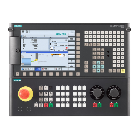
Introduction 2.2 Operator panel fronts Operator panel fronts 2.2.1 Overview Introduction The display (screen) and operation (e.g. hardkeys and softkeys) of the SINUMERIK Operate user interface use the operator panel front. In this example, the OP 010 operator panel front is used to illustrate the components that are available for operating the controller and machine tool. - Page 27 Introduction 2.2 Operator panel fronts Operator controls and indicators Alphabetic key group With the <Shift> key pressed, you activate the special characters on keys with double assign‐ ments, and write in the uppercase. Note: Depending on the particular configuration of your control system, uppercase letters are always written Numerical key group With the <Shift>...
-
Page 28: Keys Of The Operator Panel
Introduction 2.2 Operator panel fronts Manual operator components and networking; SINUMERIK 840D sl 2.2.2 Keys of the operator panel The following keys and key combinations are available for operation of the control and the machine tool. Keys and key combinations Function <ALARM CANCEL>... - Page 29 Introduction 2.2 Operator panel fronts <NEXT WINDOW> + <CTRL> + <SHIFT> ● Moves the cursor to the beginning of a program. ● Moves the cursor to the first row of the current column. ● Selects a contiguous selection from the current cursor position up to the target position.
- Page 30 Introduction 2.2 Operator panel fronts <Cursor up> ● Editing box Moves the cursor into the next upper field. ● Navigation – Moves the cursor in a table to the next cell upwards. – Moves the cursor upwards in a menu screen. <Cursor up>...
- Page 31 Introduction 2.2 Operator panel fronts <END> + <SHIFT> Moves the cursor to the last entry. Selects a contiguous selection from the cursor position up to the end of a program block. <END> + <CTRL> Moves the cursor to the last entry in the last line of the actual column or to the end of a program.
- Page 32 Introduction 2.2 Operator panel fronts <CTRL> + <E> Calls the "Ctrl Energy" function. <CTRL> + <F> Opens the search dialog in the machine data and setting data lists, when loading and saving in the MDI editor as well as in the program manager and in the system data.
- Page 33 Introduction 2.2 Operator panel fronts <CTRL> + <ALT> + <C> Creates a complete standard archive (.ARC) on an external data carrier (USB-FlashDrive) (for 840D sl / 828D). Note: The complete backup via this key combination is only suitable for diagnostic purposes. Note: Please refer to the machine manufacturer's specifications.
- Page 34 Introduction 2.2 Operator panel fronts <DEL> + <CTRL> ● Editing box Deletes the first word to the right of the cursor. ● Navigation Deletes all characters. <Spacebar> ● Editing box Inserts a space. ● Switches between several specified options in selection lists and in selection boxes.
- Page 35 Introduction 2.2 Operator panel fronts <INPUT> ● Completes input of a value in the entry field. ● Opens a directory or a program. ● Inserts an empty program block if the cursor is positioned at the end of a program block. ●...
-
Page 36: Machine Control Panels
2.3.1 Overview The machine tool can be equipped with a machine control panel by Siemens or with a specific machine control panel from the machine manufacturer. You use the machine control panel to initiate actions on the machine tool such as traversing an axis or starting the machining of a workpiece. - Page 37 Introduction 2.3 Machine control panels Operator controls EMERGENCY STOP button Press the button in situations where: ● life is at risk. ● there is the danger of a machine or workpiece being damaged. All drives will be stopped with the greatest possible braking torque. Machine manufacturer For additional responses to pressing the EMERGENCY STOP button, please refer to the machine manufacturer's instructions.
- Page 38 Introduction 2.3 Machine control panels <REF POINT> Approach reference point. Inc <VAR>(Incremental Feed Variable) Incremental mode with variable increment size. Inc (incremental feed) Incremental mode with predefined increment size of 1, ..., 10000 increments. Machine manufacturer A machine data code defines how the increment value is inter‐ preted.
- Page 39 Introduction 2.3 Machine control panels Feed control with override switch <FEED STOP> Stops execution of the running program and shuts down axis drives. <FEED START> Enable for program execution in the current block and enable for ramp-up to the feedrate value specified by the program. Milling Operating Manual, 08/2018, 6FC5398-7CP41-0BA0...
-
Page 40: User Interface
Introduction 2.4 User interface User interface 2.4.1 Screen layout Overview Active operating area and mode Alarm/message line Channel operational messages Display for ● Active tool T ● Current feedrate F ● Active spindle with current status (S) ● Spindle utilization rate in percent ●... -
Page 41: Status Display
Introduction 2.4 User interface Display of active G functions, all G functions, auxiliary functions and input window for different functions (for example, skip blocks, program control). Horizontal softkey bar Dialog line to provide additional user notes. Operating window with program block display Position display of the axes in the actual values window Channel state and program control Program name... - Page 42 Introduction 2.4 User interface Display Description "Program" operating area "Program manager" operating area "Diagnosis" operating area "Start-up" operating area Active mode or submode Display Description "Jog" mode "MDA" mode "Auto" mode "Teach In" submode "Repos" submode "Ref Point" submode Alarms and messages Display Description Alarm display...
-
Page 43: Actual Value Window
Introduction 2.4 User interface The displays in the second line can be configured. Machine manufacturer Please refer to the machine manufacturer's specifications. Third line Display Description Display of channel status. If several channels are present on the machine, the channel name is also displayed. - Page 44 Introduction 2.4 User interface Work/Machine The displayed coordinates are based on either the machine coordinate system or the workpiece coordinate system. The machine coordinate system (Machine), in contrast to the workpiece coordinate system (Work), does not take any work offsets into consideration. You can use the "Machine actual values"...
-
Page 45: T,F,S Window
Introduction 2.4 User interface Display Meaning Collision monitoring Collision avoidance is activated for the JOG and MDA or (only 840D sl) AUTOMATIC modes. Note: The $MN_JOG_MODE_MASK machine data can be set to suppress the display of the symbol. Please refer to the machine manufacturer's specifications. Collision avoidance is deactivated for the JOG and MDA or AUTOMATIC modes. - Page 46 Introduction 2.4 User interface Display Meaning Cutting edge of the current tool The tool is displayed with the associated tool type symbol corresponding to the actual coordinate system in the selected cutting edge position. If the tool is swiveled, then this is taken into account in the display of the cutting edge position.
-
Page 47: Current Block Display
Introduction 2.4 User interface Display Meaning Override Display as a percentage Spindle utilization Display between 0 and 100% rate The upper limit value can be greater than 100%. See machine manufacturer's specifications. Note Display of logical spindles If the spindle converter is active, logical spindles are displayed in the workpiece coordinate system. - Page 48 Introduction 2.4 User interface Display Meaning Blue background Estimated machining time of the program block (simulation) Yellow background Wait time (automatic mode or simulation) Highlighting of selected G code commands or keywords In the program editor settings, you can specify whether selected G code commands are to be highlighted in color.
-
Page 49: Operation Via Softkeys And Buttons
Introduction 2.4 User interface See also Setting for automatic mode (Page 267) 2.4.6 Operation via softkeys and buttons Operating areas/operating modes The user interface consists of different windows featuring eight horizontal and eight vertical softkeys. You operate the softkeys with the keys next to the softkey bars. You can display a new window or execute functions using the softkeys. -
Page 50: Entering Or Selecting Parameters
Introduction 2.4 User interface Use the "Return" softkey to close an open window. Use the "Cancel" softkey to exit a window without accepting the entered values and return to the next highest window. When you have entered all the necessary parameters in the parameter screen form correctly, you can close the window and save the parameters using the "Accept"... - Page 51 Introduction 2.4 User interface Select the required setting using the <Cursor down> and <Cursor up> keys. If required, enter a value in the associated input field. Press the <INPUT> key to complete the parameter input. Changing or calculating parameters If you only want to change individual characters in an input field rather than overwriting the entire entry, switch to insertion mode.
-
Page 52: Pocket Calculator
Introduction 2.4 User interface You cannot accept the parameters if they are incomplete or obviously erroneous. In this case, you can see from the dialog line which parameters are missing or were entered incorrectly. Press the "OK" softkey. - OR - Press the "Accept"... -
Page 53: Pocket Calculator Functions
Introduction 2.4 User interface 2.4.9 Pocket calculator functions The called operations continue to be displayed in the entry field of the calculator until the value is calculated. This allows you to subsequently modify entries and to nest functions. The following save and delete functions are provided for modifications: Function Buffer value (Memory Save) Retrieve from buffer memory (Memory Recall ) - Page 54 Introduction 2.4 User interface Calculating trigonometric functions Check whether the angles are specified in radians "RAD" or in degrees "DEG". Press the "RAD" key to calculate the trigonometric functions in degrees "DEG". The designation of the key changes to "DEG". - OR - Press the "DEG"...
-
Page 55: Context Menu
Introduction 2.4 User interface Press the "INCH" key to convert millimeters to inches. The button is highlighted in blue. Press the "=" key on the calculator. The calculated value is displayed in the entry field. The key for the unit is highlighted in gray once again. -
Page 56: Entering Chinese Characters
Introduction 2.4 User interface Press the <INPUT> key. The user interface changes to the selected language. Note Changing the language directly on the input screens You can switch between the user interface languages available on the controller directly on the user interface by pressing the key combination <CTRL + L>. 2.4.12 Entering Chinese characters 2.4.12.1... -
Page 57: Entering Asian Characters
Introduction 2.4 User interface Structure of the editor Figure 2-4 Example: Pinyin input Figure 2-5 Example: Zhuyin input Functions Pinyin input Entering Latin letters Editing the dictionary Dictionaries The simplified Chinese and traditional Chinese dictionaries that are supplied can be expanded: ●... - Page 58 Introduction 2.4 User interface Procedure Editing characters using the Pinyin method Open the screen form and position the cursor on the input field. Press the <Alt +S> keys. The editor is displayed. Enter the desired phonetic notation using Latin letters. Use the upper input field for traditional Chinese.
-
Page 59: Editing The Dictionary
Introduction 2.4 User interface To select the associated character, press the <cursor right> or <cursor left> keys. Press the <input> key to enter the character. 2.4.12.3 Editing the dictionary Learning function of the input editor Requirement: The control has been switched over to Chinese. An unknown phonetic notation has been entered into the input editor. -
Page 60: Entering Korean Characters
Introduction 2.4 User interface Pinyin phonetic spelling <TAB> Chinese characters <LF> Pinyin phonetic spelling <TAB> Chinese character1<TAB> Chinese character2 <TAB> … <LF> <TAB> - tab key <LF> - line break Store the created dictionary in one of the following paths: ../user/sinumerik/hmi/ime/ ../oem/sinumerik/hmi/ime/ When the Chinese editor is called the next time, it enters the content of the dictionary into the... - Page 61 Introduction 2.4 User interface Korean keyboard To enter Korean characters, you will need a keyboard with the keyboard assignment shown below. In terms of key layout, this keyboard is the equivalent of an English QWERTY keyboard and individual events must be grouped together to form syllables. Structure of the editor Functions Editing characters using a matrix...
- Page 62 Introduction 2.4 User interface Procedure Editing characters using the keyboard Open the screen form and position the cursor on the input field. Press the <Alt +S> keys. The editor is displayed. Switch to the "Keyboard - Matrix" selection box. Select the keyboard. Switch to the function selection box.
-
Page 63: Protection Levels
Introduction 2.4 User interface Press the <BACKSPACE> softkey to delete entered phonetic notations. Press the <input> key to enter the character into the input field. 2.4.14 Protection levels The input and modification of data in the control system is protected by passwords at sensitive places. -
Page 64: Online Help In Sinumerik Operate
Introduction 2.4 User interface Diagnostics operating area Protection level Keyswitch 3 (protection level 4) User (protection level 3) User (protection level 3) Manufacturer (protection level 1) User (protection level 3) Service (protection level 2) Start-up operating area Protection levels End user (protection level 3) Keyswitch 3 (protection level 4) - Page 65 Introduction 2.4 User interface ● Lists of the machine data ● Lists of the setting data ● Lists of the drive parameters ● List of all alarms Procedure Calling context-sensitive online help You are in an arbitrary window of an operating area. Press the <HELP>...
- Page 66 Introduction 2.4 User interface Press the <Follow reference> softkey or the <INPUT> key to display the help page for the selected topic. Press the "Current topic" softkey to return to the original help. Searching for a topic Press the "Search" softkey. The "Search in Help for: "...
- Page 67 Introduction 2.4 User interface Press the "Transfer to editor" softkey. The selected G function is taken into the program at the cursor position. Press the "Exit help" softkey again to close the help. See also Additional functions in the input screens (Page 313) Milling Operating Manual, 08/2018, 6FC5398-7CP41-0BA0...
- Page 68 Introduction 2.4 User interface Milling Operating Manual, 08/2018, 6FC5398-7CP41-0BA0...
-
Page 69: Multitouch Operation With Sinumerik Operate
Multitouch operation with SINUMERIK Operate Multitouch panels The "SINUMERIK Operate Generation 2" user interface has been optimized for multitouch operation. You can execute all actions by touch and finger gestures. Using SINUMERIK Operate is much quicker with touch operation and finger gestures. Machine manufacturer Please observe the information provided by the machine manufacturer. -
Page 70: Touch-Sensitive User Interface
Multitouch operation with SINUMERIK Operate 3.2 Touch-sensitive user interface Touch-sensitive user interface When using touch panels, wear thin gloves made of cotton or gloves for touch-sensitive glass user interfaces with capacitive touch function. If you are using somewhat thicker gloves, then exert somewhat more pressure when using the touch panel. -
Page 71: Finger Gestures
Multitouch operation with SINUMERIK Operate 3.3 Finger gestures Finger gestures Finger gestures ● Select window ● Select object (e.g. NC set) ● Activate entry field – Enter or overwrite value – Tap again to change the value Tap with 2 fingers ●... - Page 72 Multitouch operation with SINUMERIK Operate 3.3 Finger gestures Flick horizontally with one finger ● Scroll in lists with many columns Spread ● Zoom in on graphic contents (e.g. simulation, mold making view) Pinch ● Zoom out from graphic contents (e.g. simulation, mold making view) Pan with one finger ●...
- Page 73 Multitouch operation with SINUMERIK Operate 3.3 Finger gestures Tap and hold using 2 fingers ● Open cycles line by line to change (without input screen form) Tapping with 2 index fingers – only for 840D sl ● Tap with two fingers simultaneously in the lower right- and left-hand corners to open the TCU menu.
-
Page 74: Multitouch User Interface
Multitouch operation with SINUMERIK Operate 3.4 Multitouch user interface Multitouch user interface 3.4.1 Screen layout Touch and gesture operator controls for SINUMERIK Operate with the "SINUMERIK Operate Generation 2" user interface. ① Changing the channel ② Cancel alarms ③ Function key block ④... -
Page 75: Further Operator Touch Controls
Multitouch operation with SINUMERIK Operate 3.4 Multitouch user interface Operator control Function Undo Multiple changes are undone one by one. As soon as a change has been completed in an input field, this function is no longer available. Restoring Multiple changes are restored one by one. As soon as a change has been completed in an input field, this function is no longer available. -
Page 76: Virtual Keyboard
Multitouch operation with SINUMERIK Operate 3.4 Multitouch user interface 3.4.4 Virtual keyboard If you called the virtual keyboard using the function key block, then you have the option of adapting the key assignment using the shift keys. ① Shift key for uppercase and lowercase letters ②... -
Page 77: Expansion With Side Screen
Multitouch operation with SINUMERIK Operate 3.5 Expansion with side screen Expansion with side screen 3.5.1 Overview Panels in widescreen format provide the possibility of using the extra area to display additional elements. In addition to the SINUMERIK Operate screen, displays and virtual keys are shown to provide faster information and operation. - Page 78 Multitouch operation with SINUMERIK Operate 3.5 Expansion with side screen Navigation bar Operator control Function Opens the "Machinery" operating area. Opens the tool list in the "Parameter" operating area. Opens the "Work offset" window in the "Parameter" operating area. Opens the "Program" operating area. Opens the "Program manager"...
-
Page 79: Standard Widgets
Multitouch operation with SINUMERIK Operate 3.5 Expansion with side screen 3.5.3 Standard widgets Open sidescreen ● Tap the arrow on the navigation bar to show the sidescreen. The standard widgets are displayed in minimized form as the header line. ① Widget header lines ②... -
Page 80: Zero Point" Widget
Multitouch operation with SINUMERIK Operate 3.5 Expansion with side screen 3.5.5 "Zero point" widget The widget includes values of the active work offset for all configured axes. The approximate and detailed offset, as well as rotation, scaling and mirroring are displayed for each axis. -
Page 81: Tool" Widget
Multitouch operation with SINUMERIK Operate 3.5 Expansion with side screen 3.5.8 "Tool" widget The widget contains the geometry and wear data for the active tool. The following information is additionally displayed depending on the machine configuration: ● EC: Active location-dependent offset - setting up offset ●... -
Page 82: Program Runtime" Widget
Multitouch operation with SINUMERIK Operate 3.5 Expansion with side screen 3.5.10 "Program runtime" widget The widget contains the following data: ● Total runtime of the program ● Time remaining to end of program This data is estimated for the first program run. Additionally, progress of the program is visualized in a bar chart as a percentage. -
Page 83: Example 1: Abc Keyboard In The Sidescreen
Multitouch operation with SINUMERIK Operate 3.5 Expansion with side screen 3.5.12 Example 1: ABC keyboard in the sidescreen ① ABC keyboard ② Key to display the keyboard Milling Operating Manual, 08/2018, 6FC5398-7CP41-0BA0... -
Page 84: Example 2: Machine Control Panel In The Sidescreen
Multitouch operation with SINUMERIK Operate 3.5 Expansion with side screen 3.5.13 Example 2: Machine control panel in the sidescreen ① Machine control panel ② Key to display the machine control panel Milling Operating Manual, 08/2018, 6FC5398-7CP41-0BA0... -
Page 85: Sinumerik Operate Display Manager (840D Sl Only)
Multitouch operation with SINUMERIK Operate 3.6 SINUMERIK Operate Display Manager (840D sl only) SINUMERIK Operate Display Manager (840D sl only) 3.6.1 Overview With a panel with full HD resolution (1920x1080), you have the possibility to work with the Display Manager. The Display Manager permits you to see a lot of information at a glance. -
Page 86: Screen Layout
Multitouch operation with SINUMERIK Operate 3.6 SINUMERIK Operate Display Manager (840D sl only) 3.6.2 Screen layout The standard supply of a SINUMERIK Operate Display Manager offers the option of choosing between 3-display areas and 4-display areas. ① SINUMERIK Operate with navigation bar for switchover of the operating area ②... - Page 87 Multitouch operation with SINUMERIK Operate 3.6 SINUMERIK Operate Display Manager (840D sl only) Operator control Function 4 display areas ● SINUMERIK Operate (with function block) ● Widget area ● Applications area (PDF, virtual keyboard) ● Area with virtual keyboard Mirroring display areas Mirrors the selected arrangement of the display areas.
- Page 88 Multitouch operation with SINUMERIK Operate 3.6 SINUMERIK Operate Display Manager (840D sl only) Operator control Function Minimizing the display area The area with the SINUMERIK Operate and the area for the applications are reduced back to their original size. Machine Control Panel Shows a machine control panel.
-
Page 89: Setting Up The Machine
Setting up the machine Switching on and switching off Startup When the control starts up, the main screen opens according to the operating mode specified by the machine manufacturer. In general, this is the main screen for the "REF POINT" submode. -
Page 90: Approaching A Reference Point
Setting up the machine 4.2 Approaching a reference point Approaching a reference point 4.2.1 Referencing axes Your machine tool can be equipped with an absolute or incremental path measuring system. An axis with incremental path measuring system must be referenced after the controller has been switched on –... -
Page 91: User Agreement
Setting up the machine 4.2 Approaching a reference point Press the <-> or <+> key. The selected axis moves to the reference point. If you have pressed the wrong direction key, the action is not accepted and the axes do not move. A symbol is shown next to the axis if it has been referenced. - Page 92 Setting up the machine 4.2 Approaching a reference point Press the "User enable" softkey. The "User Agreement" window opens. It shows a list of all machine axes with their current position and SI position. Position the cursor in the "Acknowledgement" field for the axis in ques‐ tion.
-
Page 93: Operating Modes
Setting up the machine 4.3 Operating modes Operating modes 4.3.1 General You can work in three different operating modes. "JOG" mode "JOG" mode is used for the following preparatory actions: ● Approach reference point, i.e. the machine axis is referenced ●... -
Page 94: Modes Groups And Channels
Setting up the machine 4.3 Operating modes Selecting "Repos" Press the <REPOS> key. "MDI" mode (Manual Data Input) In "MDI" mode, you can enter and execute G code commands non-modally to set up the machine or to perform a single action. Selecting "MDI"... -
Page 95: Channel Switchover
Setting up the machine 4.3 Operating modes Example Control with 4 channels, where machining is carried out in 2 channels and 2 other channels are used to control the transport of the new workpieces. Mode group 1 channel 1 (machining) Channel 2 (transport) Mode group 2 channel 3 (machining) Channel 4 (transport) -
Page 96: Settings For The Machine
Setting up the machine 4.4 Settings for the machine Settings for the machine 4.4.1 Switching over the coordinate system (MCS/WCS) The coordinates in the actual value display are relative to either the machine coordinate system or the workpiece coordinate system. By default, the workpiece coordinate system is set as a reference for the actual value display. - Page 97 Setting up the machine 4.4 Settings for the machine The following conditions must be met before you can switch between units of measurement: ● The corresponding machine data are set. ● All channels are in the reset state. ● The axes are not being traversed via "JOG", "DRF", and the "PLC". ●...
-
Page 98: Setting The Zero Offset
Setting up the machine 4.4 Settings for the machine 4.4.3 Setting the zero offset You can enter a new position value in the actual value display for individual axes when a settable zero offset is active. The difference between the position value in the machine coordinate system MCS and the new position value in the workpiece coordinate system WCS is saved permanently in the currently active zero offset (e.g. - Page 99 Setting up the machine 4.4 Settings for the machine Procedure Select the "JOG" mode in the "Machine" operating area. Press the "Set ZO" softkey. - OR - Press the ">>", "REL act. vals" and "Set REL" softkeys to set position values in the relative coordinate system.
-
Page 100: Measure Tool
Setting up the machine 4.5 Measure tool Measure tool 4.5.1 Overview The geometries of the machining tool must be taken into consideration when executing a part program. These are stored as tool offset data in the tool list. Each time the tool is called, the control considers the tool offset data. -
Page 101: Measuring Drilling And Milling Tools With The Workpiece Reference Point
Setting up the machine 4.5 Measure tool Reference point When measuring the tool length you can either use the workpiece or a fixed point in the machine coordinate system, e.g. a mechanical test socket or a fixed point in combination with a distance gauge as the reference point. -
Page 102: Measuring Drilling And Milling Tools With Fixed Reference Point
Setting up the machine 4.5 Measure tool Note Tool measurement is only possible with an active tool. 4.5.4 Measuring drilling and milling tools with fixed reference point Procedure Insert the tool you want to measure in the spindle. Select "JOG" mode in the "Machine" operating area. Press the "Meas. -
Page 103: Measuring Radius Or Diameter
Setting up the machine 4.5 Measure tool If you are using a distance gauge, travel as close to the fixed point as possible, measure the gap with the distance gauge and enter the value in "DZ". The distance gauge is approached with the spindle stationary. Press the "Set length"... -
Page 104: Fixed Point Calibration
Setting up the machine 4.5 Measure tool 4.5.6 Fixed point calibration If you want to use a fixed point as the reference point in manual measurement of the tool length, you must first determine the position of the fixed point relative to the machine zero. Test socket You can use a mechanical test socket as the fixed point, for example. - Page 105 Setting up the machine 4.5 Measure tool The corresponding windows can be adapted to the measurement tasks in order to automatically measure tools. Adapting the user interface to calibrating and measuring functions The following selection options can be switched-in or switched-out: ●...
- Page 106 Setting up the machine 4.5 Measure tool Individually checking teeth Before or after machining you can check if any cutting edges of the milling tool have broken off. If it is noticed during the check of the cutting edges that not all cutting edges or teeth are present, you will receive a corresponding message.
-
Page 107: Calibrating The Electrical Tool Probe
Setting up the machine 4.5 Measure tool 4.5.8 Calibrating the electrical tool probe If you want to measure your tools automatically, you must first determine the position of the tool probe on the machine table with reference to the machine zero. Tool probes are typically shaped like a cube or a cylindrical disk. -
Page 108: Manually Measuring A Turning Tool (For Milling/Turning Machine)
Setting up the machine 4.5 Measure tool Click in the selection field "Spindle rotation" entry "Yes" if you want to perform the "Calibration with rotation". Press the <CYCLE START> key. Calibration is automatically executed at the measuring feedrate. The dis‐ tance measurements between the machine zero and tool probe are cal‐... -
Page 109: Manually Measuring A Turning Tool Using A Tool Probe (For Milling/Turning Machine)
Setting up the machine 4.5 Measure tool Press the "OK" softkey. The tool is transferred into the window "Measure: Length manual". Press the "X" or "Z" softkey, depending on which tool length you want to measure. Scratch the required edge using the tool. If you do not wish to keep the tool at the workpiece edge, then press the "Save position"... - Page 110 Setting up the machine 4.5 Measure tool Adapting the user interface to the calibrating and measuring function The tool offset data is calculated from the known position of the tool carrier reference point and the probe. You can adapt the corresponding windows to the measurement tasks in order to automatically measure tools.
-
Page 111: Logging Tool Measurement Results
Setting up the machine 4.5 Measure tool Press the "X" or "Z" softkey, depending on which tool length you want to measure. Manually position the tool in the vicinity of the tool probe in such a way that any collisions can be avoided when the tool probe is being traversed in the corresponding direction. - Page 112 Setting up the machine 4.5 Measure tool Procedure You are in the "JOG" mode and have pressed the "Measure tool" softkey. The "Measurement log" softkey cannot be used. Insert the tool, select the measuring version and measure the tool as usual.
-
Page 113: Measuring The Workpiece Zero
Setting up the machine 4.6 Measuring the workpiece zero Measuring the workpiece zero 4.6.1 Overview The reference point for programming a workpiece is always the workpiece zero. You can determine the workpiece zero on the following workpiece elements: ● Edge (Page 121) ●... - Page 114 Setting up the machine 4.6 Measuring the workpiece zero To do this, you will need a positionable spindle as well as an electronic 3D workpiece probe. The radius of the probe ball of the electrical probe must be determined once by calibration and entered in the tool data.
- Page 115 Setting up the machine 4.6 Measuring the workpiece zero Note "Measuring only" for automatic measuring If "Measuring only" is selected as offset target, then instead of the "Set WO" softkey, the "Calculate" softkey is displayed. The measuring versions "Set edge", "Rectangular pocket", "Rectangular spigot", "1 circular spigot"...
- Page 116 Setting up the machine 4.6 Measuring the workpiece zero Entering the calibration feedrate The actual calibration feedrate can be entered into this entry field. The calibration feedrate is stored in the calibration data and is used for the measurements. If the entry field does not exist, then the calibration feedrate from a central parameter is used. Selecting the work offset as basis for the measurement A work offset can be selected as measurement basis to flexibly adapt to the measuring tasks.
-
Page 117: Sequence Of Operations
Setting up the machine 4.6 Measuring the workpiece zero Rotary axes If your machine has rotary axes, you can include these rotary axes in the measurement and setup procedure. If you store the workpiece zero in a work offset, rotary axis positioning may be necessary in the following cases. -
Page 118: Examples With Manual Swivel
Setting up the machine 4.6 Measuring the workpiece zero Pre-positioning If you want to preposition a rotary axis before measuring with "Align edge", move the rotary axis so that your workpiece is approximately parallel to the coordinate system. Set the relevant rotary axis angle to zero with "Set WO". Measurement with "Align edge" will then correct the value for rotary axis offset or include it in the coordinate rotation and align the workpiece edge precisely. -
Page 119: Setting The Edge
Setting up the machine 4.6 Measuring the workpiece zero 8. Measure workpiece Apply "Set edge Z" to define the offset in Z. 9. Start part program to remachine under AUTO. Start the program with swivel zero. Second example Measuring workpieces in swiveled states. The workpiece is to be probed in the X direction even though the probe cannot approach the workpiece in the X direction because of an obstructing edge (e.g. - Page 120 Setting up the machine 4.6 Measuring the workpiece zero Procedure Select the "Machine" operating area and press the <JOG> key. Press the "Workpiece zero" and "Set edge" softkeys. The "Set Edge" window opens. Select "Measuring only" if you only want to display the measured values. - OR - In the selection box, select the desired zero offset in which you want to store the zero point.
-
Page 121: Edge Measurement
Setting up the machine 4.6 Measuring the workpiece zero Note Settable zero offsets The labeling of the softkeys for the settable zero offsets varies, i.e. the settable zero offsets configured on the machine are displayed (examples: G54…G57, G54…G505, G54…G599). Please refer to the machine manufacturer's specifications. 4.6.5 Edge measurement The following options are available to you when measuring an edge:... - Page 122 Setting up the machine 4.6 Measuring the workpiece zero - OR - Press the "Distance between 2 edges" softkey. - OR - If these softkeys are not listed, press any vertical softkey (with the excep‐ tion of "Set edge") and in the drop-down list, select the desired measure‐ ment version.
-
Page 123: Measuring A Corner
Setting up the machine 4.6 Measuring the workpiece zero Note Settable zero offsets The labeling of the softkeys for the settable zero offsets varies, i.e. the settable zero offsets configured on the machine are displayed (examples: G54…G57, G54…G505, G54…G599). Please refer to the machine manufacturer's specifications. Automatic measurement Prepare the measurement (see steps 1 to 5 above). - Page 124 Setting up the machine 4.6 Measuring the workpiece zero workpiece reference edge (line through P1 and P2) and the reference axis in the working plane (1st geometry axis of the working plane) and inner angle β of the corner. Note The coordinate system shown in the help displays is always in relation to the currently set workpiece coordinate system.
- Page 125 Setting up the machine 4.6 Measuring the workpiece zero Press the "Select WO" softkey to select a settable work offset. In the window "Work offset – G54 ... G599", select a work offset, in which the zero point should be saved and press the "In manual" softkey. You return to the measurement window.
-
Page 126: Measuring A Pocket And Hole
Setting up the machine 4.6 Measuring the workpiece zero Automatic measurement Prepare the measurement (see steps 1 to 6 above). Approach measuring point P1 with the workpiece probe and press the <CYCLE START> key. This starts the automatic measuring process. The position of measuring point 1 is measured and stored. - Page 127 Setting up the machine 4.6 Measuring the workpiece zero Measuring three holes The workpiece with the three holes to be measured is clamped to the work table in any position. Four points are automatically measured in the three holes and the hole centers are calculated from them.
- Page 128 Setting up the machine 4.6 Measuring the workpiece zero Procedure Select the "Machine" operating area and press the <JOG> key. Press the "Workpiece zero" softkey. Press the "Rectangular pocket" softkey. - OR - Press the "1 hole" softkey. - OR - If these softkeys are not listed, press any vertical softkey (with the excep‐...
-
Page 129: Measuring A Spigot
Setting up the machine 4.6 Measuring the workpiece zero Repeat steps 6 and 7 to measure and save measuring points P2, P3 and Press the "Calculate" softkey. The length, width, and center point of the rectangular pocket or diameter and center point of the hole are calculated and displayed. - OR - Press the "Set WO"... - Page 130 Setting up the machine 4.6 Measuring the workpiece zero Measuring three circular spigots The workpiece is located anywhere on the work table and has three spigots. Four points are automatically measured at the three spigots and the spigot centers are calculated from them. A circle is placed through the three center points and the circle center and circle diameter are determined.
- Page 131 Setting up the machine 4.6 Measuring the workpiece zero - OR - Press the "1 circular spigot" softkey. - OR - If these softkeys are not listed, press any vertical softkey (with the excep‐ tion of "Set edge") and in the drop-down list, select the desired measure‐ ment version.
- Page 132 Setting up the machine 4.6 Measuring the workpiece zero Note Settable work offsets The labeling of the softkeys for the settable work offsets varies, i.e. the settable work offsets configured on the machine are displayed (examples: G54…G57, G54…G505, G54…G599). Please refer to the machine manufacturer's specifications. Automatic measurement Select the "Measure workpiece zero"...
- Page 133 Setting up the machine 4.6 Measuring the workpiece zero 2 circular ● Enter the approximate diameter of the spigot into "Øspigot". spigots ● Enter the infeed value in "DZ" to determine the measuring depth. ● Under "Angle offs.", select entry "Coor. rotation" or "Rotary axis A, B, C".
-
Page 134: Aligning The Plane
Setting up the machine 4.6 Measuring the workpiece zero After the measurement has been successfully completed, P2, P3 and P4 are stored and the softkeys "P2 stored", "P3 stored", and "P4 stored" become active. … Press the "Calculate" or "Set WO" softkey. Rectangular The length, width, and center point of the rectangular spigot are calcula‐... - Page 135 Setting up the machine 4.6 Measuring the workpiece zero Requirement You can insert any tool in the spindle for scratching when measuring the workpiece zero manually. An electronic workpiece probe is inserted in the spindle and activated when measuring the workpiece zero automatically.
-
Page 136: Defining The Measurement Function Selection
Setting up the machine 4.6 Measuring the workpiece zero Press the "Save P1" softkey. Then traverse the tool to the second and third measuring point and press the "Save P2" and "Save P3" softkeys. Press the "Set ZO" or "Calculate" softkey. Angles α... -
Page 137: Corrections After Measurement Of The Zero Point
Setting up the machine 4.6 Measuring the workpiece zero Procedure The "Measure workpiece zero" function is selected. Press the softkey that you wish to assign to a new measurement version, e.g. "1 circular spigot". The "1 Circular Spigot" window opens. Open the list of measurement versions, select the desired measurement version using the <Cursor down>... -
Page 138: Logging Measurement Results For The Workpiece Zero
Setting up the machine 4.6 Measuring the workpiece zero When you press the "Set WO" softkey, the activation window opens ask‐ ing whether you want to "Activate work offset Gxxx now?". Press the "OK" softkey to activate the corrected work offset. Aligning and retracting the tool (for aligning the plane) Rotating the workpiece coordinate system makes it necessary to realign the tool to the plane. - Page 139 Setting up the machine 4.6 Measuring the workpiece zero ● Measuring version ● Input values ● Correction target ● Setpoints, measured values and differences You have the option to output the log as a text file (*.txt) or in a tabular format (*.csv). Note Processing the measurement results The tabular format is a format that can be imported by Excel (or other spreadsheet programs).
-
Page 140: Calibrating The Electronic Workpiece Probe
Setting up the machine 4.6 Measuring the workpiece zero 4.6.13 Calibrating the electronic workpiece probe 4.6.13.1 Calibration of length and radius or diameter When the electronic probes are attached to the spindle, clamping tolerances usually occur. This can lead to measurement errors. In addition, you need to determine the trigger points of the probe relative to the spindle center (trigger points). -
Page 141: Calibrate On Sphere
Setting up the machine 4.6 Measuring the workpiece zero Calibration of length Move the workpiece probe over the reference surface. Press the "Meas. workp." and "Calibrate probe" softkeys. The "Calibration: Probe" window opens. Press the "Length" softkey. Specify reference point Z0 of the surface, e.g. of the workpiece or the machine table. - Page 142 Setting up the machine 4.6 Measuring the workpiece zero Procedure Load the workpiece probe into the spindle. Enter the diameter and length approximately in the tool data. Select the "JOG" mode in the "Machine" operating area. Move the workpiece probe approximately over the center of the sphere. Press the "Meas.
-
Page 143: Settings For The Measurement Result Log
Setting up the machine 4.7 Settings for the measurement result log Settings for the measurement result log Make the following settings in the "Settings for measurement log" window: ● Log format – Text format The log in the text format is based on the display of the measurement results on the screen. - Page 144 Setting up the machine 4.7 Settings for the measurement result log See also Logging measurement results for the workpiece zero (Page 138) Logging tool measurement results (Page 111) Milling Operating Manual, 08/2018, 6FC5398-7CP41-0BA0...
-
Page 145: Zero Offsets
Setting up the machine 4.8 Zero offsets Zero offsets Following reference point approach, the actual value display for the axis coordinates is based on the machine zero (M) of the machine coordinate system (Machine). The program for machining the workpiece, however, is based on the workpiece zero (W) of the workpiece coordinate system (Work). -
Page 146: Display Active Zero Offset
Setting up the machine 4.8 Zero offsets See also Actual value window (Page 43) 4.8.1 Display active zero offset The following zero offsets are displayed in the "Zero Offset - Active" window: ● Zero offsets, for which active offsets are included, or for which values are entered. ●... - Page 147 Setting up the machine 4.8 Zero offsets In addition to the offset (course and fine), the associated rotation, scaling and mirroring are also displayed. This window is generally used only for monitoring. Display of active work offsets Work offsets MCS actual value Display of the actual value in the Machine Coordinate Sys‐...
-
Page 148: Displaying And Editing Base Zero Offset
Setting up the machine 4.8 Zero offsets Procedure Select the "Parameter" operating area. Press the "Work offset" and "Overview" softkeys. The "Work Offsets - Overview" window opens. 4.8.3 Displaying and editing base zero offset The defined channel-specific and global base offsets, divided into coarse and fine offsets, are displayed for all set-up axes in the "Zero offset - Base"... -
Page 149: Displaying And Editing Settable Zero Offset
Setting up the machine 4.8 Zero offsets 4.8.4 Displaying and editing settable zero offset All settable offsets, divided into coarse and fine offsets, are displayed in the "Work offset - G54...G599" window. Rotation, scaling and mirroring are displayed. Procedure Select the "Parameter" operating area. Press the "Work offset"... - Page 150 Setting up the machine 4.8 Zero offsets Note Settings for rotation, scaling and mirroring are specified here and can only be changed here. Tool details You can display the following details for the tool and wear data for tools: ● TC ●...
-
Page 151: Deleting A Zero Offset
Setting up the machine 4.8 Zero offsets You can edit the values directly in the table. - OR - Press the "Clear offset" softkey to reset all entered values. Press the "ZO +" or "ZO -" softkey to select the next or previous offset, respectively, within the selected area ("Active", "Base", "G54 to G599") without first having to switch to the overview window. -
Page 152: Measuring The Workpiece Zero
Setting up the machine 4.8 Zero offsets Press the "Clear offset" softkey. A confirmation prompt is displayed as to whether you really want to delete the work offset. Press the "OK" softkey to confirm that you wish to delete the work offset. 4.8.7 Measuring the workpiece zero Procedure... -
Page 153: Monitoring Axis And Spindle Data
Setting up the machine 4.9 Monitoring axis and spindle data Monitoring axis and spindle data 4.9.1 Specify working area limitations Using the "Working area limitation" function you can limit the range within which a tool should traverse in all channel axes. This function allows you to set up protection zones in the working area that are inhibited for tool motion. - Page 154 Setting up the machine 4.9 Monitoring axis and spindle data You can limit the spindle speeds in fields "Minimum" and "Maximum" within the limit values defined in the relevant machine data. Spindle speed limitation at constant cutting rate In field "Spindle speed limitation at G96", the programmed spindle speed limitation at constant cutting speed is displayed together with the permanently active limitations.
-
Page 155: Displaying Setting Data Lists
Setting up the machine 4.10 Displaying setting data lists 4.10 Displaying setting data lists You can display lists with configured setting data. Machine manufacturer Please refer to the machine manufacturer's specifications. Procedure Select the "Parameter" operating area. Press the "Setting data" and "Data lists" softkeys. The "Setting Data Lists"... -
Page 156: Handwheel Assignment
Setting up the machine 4.11 Handwheel assignment 4.11 Handwheel assignment You can traverse the axes in the machine coordinate system (Machine) or in the workpiece coordinate system (Work) via the handwheel. Software option You require the "Extended operator functions" option for the handwheel offset (only for 828D). - Page 157 Setting up the machine 4.11 Handwheel assignment Open the "Axis" selection box using the <INSERT> key, navigate to the desired axis, and press the <INPUT> key. Selecting an axis also activates the handwheel (e.g., "X" is assigned to handwheel no. 1 and is activated immediately). Press the "Handwheel"...
-
Page 158: Mda
Setting up the machine 4.12 MDA 4.12 In "MDI" mode (Manual Data Input mode), you can enter G-code commands or standard cycles block-by-block and immediately execute them for setting up the machine. You have the option of loading an MDI program or a standard program with the standard cycles directly into the MDI buffer from the program manager;... -
Page 159: Saving An Mda Program
Setting up the machine 4.12 MDA 4.12.2 Saving an MDA program Procedure Select the "Machine" operating area. Press the <MDI> key. The MDI editor opens. Create the MDI program by entering the G-code commands using the operator's keyboard. Press the "Store MDI" softkey. The "Save from MDI: Select storage location"... -
Page 160: Editing/Executing A Mdi Program
Setting up the machine 4.12 MDA 4.12.3 Editing/executing a MDI program Procedure Select the "Machine" operating area. Press the <MDI> key. The MDI editor opens. Enter the desired G-code commands using the operator’s keyboard. - OR - Enter a standard cycle, e.g. CYCLE62 (). Editing G-code commands/program blocks Edit G-code commands directly in the "MDI"... -
Page 161: Deleting An Mda Program
Setting up the machine 4.12 MDA 4.12.4 Deleting an MDA program Precondition The MDA editor contains a program that you created in the MDI window or loaded from the program manager. Procedure Press the "Delete blocks" softkey. The program blocks displayed in the program window are deleted. Milling Operating Manual, 08/2018, 6FC5398-7CP41-0BA0... - Page 162 Setting up the machine 4.12 MDA Milling Operating Manual, 08/2018, 6FC5398-7CP41-0BA0...
-
Page 163: Execution In Manual Mode
Execution in manual mode General Always use "JOG" mode when you want to set up the machine for the execution of a program or to carry out simple traversing movements on the machine: ● Synchronize the measuring system of the controller with the machine (reference point approach) ●... -
Page 164: Selecting A Tool And Spindle
Execution in manual mode 5.2 Selecting a tool and spindle Selecting a tool and spindle 5.2.1 T, S, M windows For the preparatory actions in manual mode, tool selection and spindle control are both performed centrally in a screen form. In manual mode, you can select a tool either by its name or its location number. - Page 165 Execution in manual mode 5.2 Selecting a tool and spindle Parameter Meaning Unit Gear stage Specification of the gear stage (auto, I - V) Stop position Entering the spindle position degrees Note Spindle positioning You can use this function to position the spindle at a specific angle, e.g. during a tool change. ●...
-
Page 166: Selecting A Tool
Execution in manual mode 5.2 Selecting a tool and spindle 5.2.2 Selecting a tool Procedure Select the "JOG" operating mode. Press the "T, S, M" softkey. Enter the name or the number of the tool T in the input field. - OR - Press the "Select tool”... -
Page 167: Position Spindle
Execution in manual mode 5.2 Selecting a tool and spindle If the machine has a gearbox for the spindle, set the gear stage (e.g. auto). Select a spindle direction of rotation (clockwise or counterclockwise) in the "Spindle M function" field. Press the <CYCLE START>... - Page 168 Execution in manual mode 5.2 Selecting a tool and spindle Note You can use this function to position the spindle at a specific angle, e.g. during a tool change. ● A stationary spindle is positioned via the shortest possible route. ●...
-
Page 169: Traversing Axes
Execution in manual mode 5.3 Traversing axes Traversing axes You can traverse the axes in manual mode via the Increment or Axis keys or handwheels. During a traverse initiated from the keyboard, the selected axis moves at the programmed setup feedrate. During an incremental traverse, the selected axis traverses a specified increment. -
Page 170: Traversing Axes By A Variable Increment
Execution in manual mode 5.3 Traversing axes Note When the controller is switched on, the axes can be traversed right up to the limits of the machine as the reference points have not yet been approached and the axes referenced. Emergency limit switches might be triggered as a result. -
Page 171: Positioning Axes
Execution in manual mode 5.4 Positioning axes Positioning axes In manual mode, you can traverse individual or several axes to certain positions in order to implement simple machining sequences. The feedrate / rapid traverse override is active during traversing. Procedure If required, select a tool. -
Page 172: Swiveling
Execution in manual mode 5.5 Swiveling Swiveling Manual swivel in the JOG mode provides functions that make it far easier to setup, measure, and machine workpieces with swiveled surfaces. If you want to create or correct an inclined position, the required rotations of the workpiece coordinate system around the geometry axes (X, Y, Z) are automatically converted into suitable positions of the machine kinematics. - Page 173 Execution in manual mode 5.5 Swiveling ● Swivel plane You can start the swivel plane as "new" or "additive" to a swivel plane that is already active. Note "Additive" swivel plane With "additive" swivel plane, values should only be added to the swivel data set that is already active.
- Page 174 Execution in manual mode 5.5 Swiveling ● Zero plane The zero plane corresponds to the tool plane (G17, G18, G19) including the active zero offset (G500, G54, ...). Rotations of the active zero offset and the rotary axes are taken into account for manual swiveling.
- Page 175 Execution in manual mode 5.5 Swiveling Press the "Basic setting" softkey and the <CYCLE START> key to move the machine into the initial position. If the actual zero offset does not include a rotation, then the rotary axes of the swivel data record are moved to zero. The tool is located vertically to the machining plane.
- Page 176 Execution in manual mode 5.5 Swiveling Parameter Description Unit Tool Tool tip position when swiveling Tracking The position of the tool tip is maintained during swiveling. No tracking The position of the tool tip changes during swiveling. Milling Operating Manual, 08/2018, 6FC5398-7CP41-0BA0...
-
Page 177: Manual Retraction
Execution in manual mode 5.6 Manual retraction Manual retraction In the following cases, the "Retract" function allows drilling tools to be retracted in the tool direction in the JOG mode: ● After interrupting a thread tapping operation (G33/331/G332), ● After interrupting machining operations using drilling tools (tools 200 to 299) as a result of power failure or a RESET at the machine control panel. - Page 178 Execution in manual mode 5.6 Manual retraction Use the traversing keys (e.g. Z +) to traverse the tool from the workpiece according to the retraction axis displayed in the "Retract Tool" window. Press the "Retract" softkey again when the tool is at the desired position. Milling Operating Manual, 08/2018, 6FC5398-7CP41-0BA0...
-
Page 179: Simple Face Milling Of The Workpiece
Execution in manual mode 5.7 Simple face milling of the workpiece Simple face milling of the workpiece You can use this cycle to face mill any workpiece. A rectangular surface is always machined. Selecting the machining direction In the "Direction" field, using the SELECT key, select the desired machining direction: ●... - Page 180 Execution in manual mode 5.7 Simple face milling of the workpiece Procedure Select the "Machine" operating area. Press the <JOG> key. Press the <Face milling> softkey. Press the relevant softkey to specify the lateral limitations of the work‐ piece. Select the machining type (e.g. roughing) in the "Machining" field. Select the machining direction in the "Direction"...
- Page 181 Execution in manual mode 5.7 Simple face milling of the workpiece Parameter Description Unit Direction Same direction of machining ● ● Alternating direction of machining ● ● Corner point 1 of surface in X direction (abs. or inc.) Corner point 1 of surface in Y direction (abs. or inc.) Height of blank (abs.
-
Page 182: Simple Workpiece Machining Operations With Milling/Turning Machines
Execution in manual mode 5.8 Simple workpiece machining operations with milling/turning machines Simple workpiece machining operations with milling/turning machines 5.8.1 Simple workpiece face milling (milling/turning machine) You can use this cycle to face mill any workpiece. A rectangular surface is always machined. Selecting the machining direction In the "Direction"... - Page 183 Execution in manual mode 5.8 Simple workpiece machining operations with milling/turning machines Procedure Select the "Machine" operating area. Press the <JOG> key. Press the "Machining" and "Face milling" softkeys. Press the relevant softkey to specify the lateral limitations of the work‐ piece.
-
Page 184: Simple Stock Removal Of Workpiece (For Milling/Turning Machine)
Execution in manual mode 5.8 Simple workpiece machining operations with milling/turning machines Parameter Description Unit Machining The following machining operations can be selected: ● ∇ (roughing) ● ∇∇∇ (finishing) Direction Same direction of machining ● ● Alternating direction of machining ●... - Page 185 Execution in manual mode 5.8 Simple workpiece machining operations with milling/turning machines Retraction plane / safety clearance The retraction plane and safety clearance are set using the machine data $SCS_MAJOG_SAFETY_CLEARANCE or $SCS_MAJOG_RELEASE_PLANE. Machine manufacturer Please observe the information provided by the machine manufacturer. Direction of spindle rotation If the "ShopMill/ShopTurn"...
- Page 186 Execution in manual mode 5.8 Simple workpiece machining operations with milling/turning machines Parameters Description Unit Tool name Cutting edge number Name of the swivel data record β Angle of the tool to the axis of rotation degrees β = 0° β...
- Page 187 Execution in manual mode 5.8 Simple workpiece machining operations with milling/turning machines Parameters Description Unit Machining ● Face direction ● Longitudinal Reference point ∅ (abs) Reference point (abs) End point X ∅ (abs) or end point X in relation to X0 (inc) End point Z (abs) or end point Z in relation to X0 (inc) FS1...FS3 or R1...R3 Chamfer width (FS1...FS3) or rounding radius (R1...R3)
-
Page 188: Default Settings For Manual Mode
Execution in manual mode 5.9 Default settings for manual mode Default settings for manual mode Specify the configurations for the manual mode in the "Settings for manual operation" window. Default settings Settings Meaning Type of feedrate Here, you select the type of feedrate. ●... -
Page 189: Machining The Workpiece
Machining the workpiece Starting and stopping machining During execution of a program, the workpiece is machined in accordance with the programming on the machine. After the program is started in automatic mode, workpiece machining is performed automatically. Preconditions The following requirements must be met before executing a program: ●... - Page 190 Machining the workpiece 6.1 Starting and stopping machining Stopping machining Press the <CYCLE STOP> key. Machining stops immediately, individual blocks do not finish execution. At the next start, execution is resumed at the same location where it stopped. Canceling machining Press the <RESET>...
-
Page 191: Selecting A Program
Machining the workpiece 6.2 Selecting a program Selecting a program Procedure Select the "Program Manager" operating area. The directory overview is opened. Select the location where the program is archived (e.g. "NC") Place the cursor on the directory containing the program that you want to select. -
Page 192: Testing A Program
Machining the workpiece 6.3 Testing a program Testing a program When testing a program, you can select that the system can interrupt the machining of the workpiece after each program block, which triggers a movement or auxiliary function on the machine. - Page 193 Machining the workpiece 6.3 Testing a program Press the <SINGLE BLOCK> key again, if the machining is not supposed to run block-by-block. The key is deselected again. If you now press the <CYCLE START> key again, the program is execu‐ ted to the end without interruption.
-
Page 194: Displaying The Current Program Block
Machining the workpiece 6.4 Displaying the current program block Displaying the current program block 6.4.1 Current block display The window of the current block display shows the program blocks currently being executed. Display of current program The following information is displayed in the running program: ●... -
Page 195: Displaying A Basic Block
Machining the workpiece 6.4 Displaying the current program block Display Meaning Blue-green font "G2" or "G3" motion command Gray font Comment Machine manufacturer You can define further highlight colors in the "sleditorwidget.ini" configuration file. Please refer to the machine manufacturer's instructions. Editing a program directly In the Reset state, you can edit the current program directly. -
Page 196: Display Program Level
Machining the workpiece 6.4 Displaying the current program block ● Other programmed addresses ● M functions Machine manufacturer Please observe the information provided by the machine manufacturer. Procedure A program is selected for execution and has been opened in the "Ma‐ chine"... - Page 197 Machining the workpiece 6.4 Displaying the current program block ● Block number, or line number ● Remain program run throughs (only for several program run throughs) Precondition A program must be selected for execution in "AUTO" mode. Procedure Press the "Program levels" softkey. The "Program levels"...
-
Page 198: Correcting A Program
Machining the workpiece 6.5 Correcting a program Correcting a program As soon as a syntax error in the part program is detected by the controller, program execution is interrupted and the syntax error is displayed in the alarm line. Correction options Depending on the state of the control system, you have various options of correcting the program. -
Page 199: Repositioning Axes
Machining the workpiece 6.6 Repositioning axes Repositioning axes After a program interruption in the automatic mode (e.g. after a tool breaks), you can move the tool away from the contour in manual mode. The coordinates of the interrupt position will be saved. The distances traversed in manual mode are displayed in the actual value window. -
Page 200: Starting Machining At A Specific Point
Machining the workpiece 6.7 Starting machining at a specific point Starting machining at a specific point 6.7.1 Use block search If you only want to execute a particular section of a program on the machine, you do not need to start the program from the beginning. You can start the program from a specified program block. - Page 201 Machining the workpiece 6.7 Starting machining at a specific point Cascaded search You can start another search from the "Search target found" state. After a search destination has been found, it is possible to continue cascading any number of times. Note Another cascaded block search can be started from the stopped program execution only if the search target has been found.
-
Page 202: Continuing Program From Search Target
Machining the workpiece 6.7 Starting machining at a specific point 6.7.2 Continuing program from search target To continue the program at the desired position, press the <CYCLE START> key twice. ● The first CYCLE START outputs the auxiliary functions collected during the search. The program is then in the Stop state. -
Page 203: Defining An Interruption Point As Search Target
Machining the workpiece 6.7 Starting machining at a specific point 6.7.4 Defining an interruption point as search target Requirement A program was selected in "AUTO" mode and interrupted during execution through CYCLE STOP or RESET. Software option You require the "Extended operator functions" option (only for 828D). Procedure Press the "Block search"... -
Page 204: Parameters For Block Search In The Search Pointer
Machining the workpiece 6.7 Starting machining at a specific point Screen form Each line represents one program level. The actual number of levels in the program depends on the nesting depth of the program. Level 1 always corresponds to the main program and all other levels correspond to subprograms. -
Page 205: Block Search Mode
Machining the workpiece 6.7 Starting machining at a specific point Parameter Meaning Number of subprogram repetitions If a subprogram is performed several times, you can enter the number of the pass here at which processing is to be continued Line: Is automatically filled for an interruption point Type "... - Page 206 Machining the workpiece 6.7 Starting machining at a specific point Block search mode Meaning Without calculation For a quick search in the main program. Calculations will not be performed during the block search, i.e. the calculation is skipped up to the target block. All settings required for execution have to be programmed from the target block (e.g.
-
Page 207: Block Search To A Position Pattern For Shopmill Programs
Machining the workpiece 6.7 Starting machining at a specific point Procedure Select the "Machine" operating area. Press the <AUTO> key. Press the "Block search" and "Block search mode" softkeys. The "Search Mode" window opens. 6.7.8 Block search to a position pattern for ShopMill programs For ShopMill programs, you have the possibility of performing a block search on the position pattern. - Page 208 Machining the workpiece 6.7 Starting machining at a specific point Enter the number of the starting hole and press the "OK" softkey. Program processing starts with the specified technology at the specified starting hole - and goes to all additional positions of this position pattern and all of the following position patterns.
-
Page 209: Controlling The Program Run
Machining the workpiece 6.8 Controlling the program run Controlling the program run 6.8.1 Program control You can change the program sequence in the "AUTO" and "MDA" modes. Abbreviation/program con‐ Mode of operation trol The program is started and executed with auxiliary function outputs and dwell times. In this mode, the axes are not traversed. -
Page 210: Skip Blocks
Machining the workpiece 6.8 Controlling the program run Activating program control You can control the program sequence however you wish by selecting and clearing the relevant checkboxes. Display / response of active program controls If program control is activated, the abbreviation of the corresponding function appears in the status display as feedback response. - Page 211 Machining the workpiece 6.8 Controlling the program run Skip levels, activate Select the corresponding checkbox to activate the desired skip level. Note The "Program Control - Skip Blocks" window is only available when more than one skip level is set up. Milling Operating Manual, 08/2018, 6FC5398-7CP41-0BA0...
-
Page 212: Overstore
Machining the workpiece 6.9 Overstore Overstore With overstore, you have the option of executing technological parameters (for example, auxiliary functions, axis feed, spindle speed, programmable instructions, etc.) before the program is actually started. The program instructions act as if they are located in a normal part program. - Page 213 Machining the workpiece 6.9 Overstore Note Block-by-block execution The <SINGLE BLOCK> key is also active in the overstore mode. If several blocks are entered in the overstore buffer, then these are executed block-by-block after each NC start Deleting blocks Press the "Delete blocks" softkey to delete program blocks you have en‐ tered.
-
Page 214: Editing A Program
Machining the workpiece 6.10 Editing a program 6.10 Editing a program With the editor, you are able to render, supplement, or change part programs. Note Maximum block length The maximum block length is 512 characters. Calling the editor ● The editor is started via the "Program correction" softkey in the "Machine" operating area. You can directly change the program by pressing the <INSERT>... - Page 215 Machining the workpiece 6.10 Editing a program Search options ● Whole words Activate this option and enter a search term if you want to search for texts/terms that are present as words in precisely this form. If, for example, you enter the search term "Finishing tool", only single "Finishing tool" terms are displayed.
-
Page 216: Replacing Program Text
Machining the workpiece 6.10 Editing a program Further search options Softkey Function The cursor is set to the first character in the program. The cursor is set to the last character in the program. 6.10.2 Replacing program text You can find and replace text in one step. Precondition The desired program is opened in the editor. -
Page 217: Copying/Pasting/Deleting A Program Block
Machining the workpiece 6.10 Editing a program Note Replacing texts ● Read-only lines (;*RO*) If hits are found, the texts are not replaced. ● Contour lines (;*GP*) If hits are found, the texts are replaced as long as the lines are not read-only. ●... - Page 218 Machining the workpiece 6.10 Editing a program Procedure Press the "Mark" softkey. - OR - Press the <SELECT> key. Select the desired program blocks with the cursor or mouse. Press the "Copy" softkey in order to copy the selection to the buffer mem‐ ory.
-
Page 219: Renumbering A Program
Machining the workpiece 6.10 Editing a program Note Copy/cut current line To copy and cut the current line where the cursor is positioned, it is not necessary to mark or select it. You have the option of making the "Cut" softkey only operable for marked program sections via editor settings. - Page 220 Machining the workpiece 6.10 Editing a program Program blocks can be created in two stages. This means that additional blocks can be formed within a particular block. You then have the option of opening and closing these blocks depending on your requirement.
-
Page 221: Opening Additional Programs
Machining the workpiece 6.10 Editing a program Press the ">>" and "View" softkeys. Press the "Open blocks" softkey if you wish to display the program with all blocks. Press the "Close blocks" softkey if you wish to display the program again in a structured form. -
Page 222: Editor Settings
Machining the workpiece 6.10 Editing a program Note Pasting program blocks JobShop machining steps cannot be copied into a G code program. Precondition You have opened a program in the editor. Procedure Press the ">>" and "Open additional program" softkeys. The "Select Additional Program"... - Page 223 Machining the workpiece 6.10 Editing a program Setting Meaning Display hidden lines ● Yes: Hidden lines marked with "*HD" (hidden) will be displayed. ● No: Lines marked with ";*HD*" will not be displayed. Note: Only visible program lines are taken into account with the "Search" and "Search and Replace"...
- Page 224 Machining the workpiece 6.10 Editing a program Setting Meaning Saving machining times Specifies how the machining times determined are processed. ● Yes A subdirectory with the name "GEN_DATA.WPD" is created in the directory of the part program. There, the machining times determined are saved in an ini file together with the name of the program.
- Page 225 Machining the workpiece 6.10 Editing a program Procedure Select the "Program" operating area. Press the "Edit" softkey. Press the ">>" and "Settings" softkeys. The "Settings" window opens. Make the required changes. Press the "Delete mach. times" softkey if you wish to delete the machining times.
-
Page 226: Working With Dxf Files
Machining the workpiece 6.11 Working with DXF files 6.11 Working with DXF files 6.11.1 Overview The "DXF-Reader" function allows you to open files created in SINUMERIK Operate directly in a CAD system and accept and store contours as well as drilling positions directly in G-code and ShopMill programs. -
Page 227: Enlarging Or Reducing The Cad Drawing
Machining the workpiece 6.11 Working with DXF files Procedure Press the "Clean" and "Layer selection" softkeys if you want to hide spe‐ cific layers. The "Layer Selection" window opens. Deactivate the required layers and press the "OK" softkey. - OR - Press the "Clean automat."... -
Page 228: Changing The Section
Machining the workpiece 6.11 Working with DXF files - OR - Press the "Details" and "Zoom elem. selection" softkeys if you want to automatically zoom elements that are in a selection set. 6.11.2.4 Changing the section If you want to move or change the size of a section of the drawing, for example, to view details or redisplay the complete drawing later, use the magnifying glass. -
Page 229: Displaying/Editing Information For The Geometric Data
Machining the workpiece 6.11 Working with DXF files Procedure Press the "Details" and "Rotate figure" softkeys. Press the "Arrow right", "Arrow left", "Arrow up", "Arrow down", "Arrow clockwise" or "Arrow counter-clockwise" softkey to change the position of the drawing. 6.11.2.6 Displaying/editing information for the geometric data Precondition The DXF file is opened in the Program Manager or in the editor. -
Page 230: Importing And Editing A Dxf File In The Editor
Machining the workpiece 6.11 Working with DXF files 6.11.3 Importing and editing a DXF file in the editor 6.11.3.1 General procedure ● Creating and opening a G-code or ShopMill program ● Calling "Contour milling" cycles and creating a "New contour" - OR - ●... -
Page 231: Assigning The Machining Plane
Machining the workpiece 6.11 Working with DXF files 6.11.3.3 Assigning the machining plane You can select the machining plane in which the contour created with the DXF reader should be located. Procedure The DXF file is opened in the editor. Press the "Select plane"... - Page 232 Machining the workpiece 6.11 Working with DXF files Procedure Select the machining range from the DXF file Press the "Reduce" and "Select range" softkeys if you want to select specific ranges of the DXF file. An orange rectangle is displayed. Press the "Range +"...
-
Page 233: Saving The Dxf File
Machining the workpiece 6.11 Working with DXF files 6.11.3.6 Saving the DXF file You can save DXF files that you have reduced and edited. Requirement The DXF file is open in the editor. Procedure Reduce file according to your requirements and/or select the working areas. - Page 234 Machining the workpiece 6.11 Working with DXF files - OR - Press the "Line" softkey. The "Row of positions" input window opens. - OR - Press the "Grid" softkey. The "Position grid" input window opens. - OR Press the "Frame" softkey. The "Position frame"...
- Page 235 Machining the workpiece 6.11 Working with DXF files Specify clearance with second clearance (for position pattern "Frame", "Grid") Once the reference point has been specified, press the "Select element" softkey repeatedly to navigate to the desired drilling position in order to specify the clearance.
-
Page 236: Accepting Contours
Machining the workpiece 6.11 Working with DXF files 6.11.3.8 Accepting contours Calling up the cycle The part program or ShopMill program to be processed has been created and you are in the editor. Press the "Mill contour" softkey. Press the "New contour" softkey. Select contour The start and end point are specified for the contour line. - Page 237 Machining the workpiece 6.11 Working with DXF files Specifying a reference point If required, specify a zero point. Contour line Press the ">>" and "Automatic" softkeys if you want to accept the largest possible number of contour elements. This makes it fast to accept contours that consist of many individual ele‐ ments.
- Page 238 Machining the workpiece 6.11 Working with DXF files Press the "Element end" softkey to place the contour end at the end of the element. - OR - Press the "Cursor" softkey to define the start of the element with the cursor at any position.
-
Page 239: Display And Edit User Variables
Machining the workpiece 6.12 Display and edit user variables 6.12 Display and edit user variables 6.12.1 Overview The defined user data may be displayed in lists. User variables The following variables can be defined: ● Global arithmetic parameters (RG) ● Arithmetic parameters (R parameters) ●... -
Page 240: Global R Parameters
Machining the workpiece 6.12 Display and edit user variables References You will find additional information in the following references: Programming Manual Job Planning / SINUMERIK 840D sl / 828D 6.12.2 Global R parameters Global R parameters are arithmetic parameters, which exist in the control itself, and can be read or written to by all channels. -
Page 241: R Parameters
Machining the workpiece 6.12 Display and edit user variables Display comments Press the ">>" and "Display comments" softkeys. The "Global R parameters with comments " window opens. Press the "Display comments" softkey once again to return to the "Global R parameters" window. Deleting R parameters and comments Press the ">>"... - Page 242 Machining the workpiece 6.12 Display and edit user variables There are no gaps in the numbering within the range. Machine manufacturer Please observe the information provided by the machine manufacturer. Procedure Select the "Parameter" operating area. Press the "User variable" softkey. Press the "R variables"...
-
Page 243: Displaying Global User Data (Gud)
Machining the workpiece 6.12 Display and edit user variables 6.12.4 Displaying global user data (GUD) Global user variables Global GUDs are NC global user data (Global User Data) that remains available after switching the machine off. GUDs apply in all programs. Definition A GUD variable is defined with the following: ●... -
Page 244: Displaying Channel Guds
Machining the workpiece 6.12 Display and edit user variables Press the "GUD selection" softkey and the "SGUD" to "GUD6" softkeys if you wish to display SGUD, MGUD, UGUD as well as GUD4 to GUD 6 of the global user variables. - OR - Press the "GUD selection"... -
Page 245: Displaying Local User Data (Lud)
Machining the workpiece 6.12 Display and edit user variables Procedure Select the "Parameter" operating area. Press the "User variable" softkey. Press the "Channel GUD" and "GUD selection" softkeys. A new vertical softkey bar appears. Press the "SGUD" ... "GUD6" softkeys if you want to display the SGUD, MGUD, UGUD as well as GUD4 to GUD 6 of the channel-specific user variables. -
Page 246: Displaying Program User Data (Pud)
Machining the workpiece 6.12 Display and edit user variables Procedure Select the "Parameter" operating area. Press the "User variable" softkey. Press the "Local LUD" softkey. 6.12.7 Displaying program user data (PUD) Program-global user variables PUDs are global part program variables (Program User Data). PUDs are valid in all main programs and subprograms, where they can also be written and read. - Page 247 Machining the workpiece 6.12 Display and edit user variables Procedure Select the "Parameter" operating area. Press the "User variable" softkey. Press the "R parameters", "Global GUD", "Channel GUD", "Local GUD" or "Program PUD" softkeys to select the list in which you would like to search for user variables.
- Page 248 Machining the workpiece 6.12 Display and edit user variables Define the desired user variable. Press the "Exit" softkey to close the editor. Activating user variables Press the "Activate" softkey. A prompt is displayed. Select whether the current values in the definition files should be retained - OR - Select whether the current values in the definition files should be deleted.
-
Page 249: Displaying G Functions And Auxiliary Functions
Machining the workpiece 6.13 Displaying G Functions and Auxiliary Functions 6.13 Displaying G Functions and Auxiliary Functions 6.13.1 Selected G functions 16 selected G groups are displayed in the "G Function" window. Within a G group, the G function currently active in the controller is displayed. Some G codes (e.g. - Page 250 Machining the workpiece 6.13 Displaying G Functions and Auxiliary Functions Group Meaning G group 7 Tool radius compensation (e.g. G40, G42) G group 8 Settable work offset (e.g. G54, G57, G500) G group 9 Offset suppression (e.g. SUPA, G53) G group 10 Exact stop - continuous-path mode (e.g.
-
Page 251: All G Functions
Machining the workpiece 6.13 Displaying G Functions and Auxiliary Functions 6.13.2 All G functions All G groups and their group numbers are listed in the "G Functions" window. Within a G group, only the G function currently active in the controller is displayed. Additional information in the footer The following additional information is displayed in the footer: ●... -
Page 252: Auxiliary Functions
Machining the workpiece 6.13 Displaying G Functions and Auxiliary Functions References ● Additional information is available in the following references: Function Manual, Basic Functions; Chapter, "Contour/orientation tolerance" ● For information about configuring the displayed G groups, refer to the following document: SINUMERIK Operate Commissioning Manual Procedure Select the "Machine"... - Page 253 Machining the workpiece 6.13 Displaying G Functions and Auxiliary Functions Procedure Select the "Machine" operating area. Press the <JOG>, <MDA> or <AUTO> key. Press the "H functions" softkey. The "Auxiliary Functions" window opens. Press the "H functions" softkey again to hide the window again. Milling Operating Manual, 08/2018, 6FC5398-7CP41-0BA0...
-
Page 254: Displaying Superimpositions
Machining the workpiece 6.14 Displaying superimpositions 6.14 Displaying superimpositions You can display handwheel axis offsets or programmed superimposed movements in the "Superimpositions" window. Input field Meaning Tool Current superimposition in the tool direction Minimum value for superimposition in the tool direction Maximum value for superimposition in the tool direction Displays the handwheel axis offset The selection of values displayed in the "Superimposition"... - Page 255 Machining the workpiece 6.14 Displaying superimpositions References Programming Guide Job Planning (PGA) Chapter: Motion-synchronous actions Status of synchronized actions You can see the status of the synchronized actions in the "Status" column. ● Waiting ● Active ● Blocked Non-modal synchronized actions can only be identified by their status display. They are only displayed during execution.
- Page 256 Machining the workpiece 6.14 Displaying superimpositions Press the "ID" softkey if you wish to hide the modal synchronized actions in the automatic mode. - AND / OR - Press the "IDS" softkey if you wish to hide static synchronized actions. - AND / OR - Press the "Blockwise"...
-
Page 257: Mold Making View
Machining the workpiece 6.15 Mold making view 6.15 Mold making view 6.15.1 Overview For large mold making programs such as those provided by CAD/CAM systems, you have the option to display the machining paths by using a fast view. This provides you with a fast overview of the program, and you have the possibility of correcting it. - Page 258 Machining the workpiece 6.15 Mold making view The following NC blocks are not supported for the mold making view: ● Helix programming ● Rational polynomials ● Other G codes or language commands All NC blocks that cannot be interpreted are simply overread. Simultaneous view of the program and mold making view You have the option of displaying the mold making view next to the program blocks in the editor.
-
Page 259: Starting The Mold Making View
Machining the workpiece 6.15 Mold making view Changing and adapting the mold making view Like simulation and simultaneous recording, you have the option of changing and adapting the mold making view in order to achieve the optimum view. ● Increasing or reducing the size of the graphic ●... -
Page 260: Specifically Jump To The Program Block
Machining the workpiece 6.15 Mold making view Preconditions ● The required program is opened in the mold making view. ● The "Graphic" softkey is active. Procedure Press the softkey "Hide G1/G2/G3" if you want to conceal the machining paths. - OR - Press the softkey "Hide G0"... -
Page 261: Searching For Program Blocks
Machining the workpiece 6.15 Mold making view Requirements ● The required program is opened in the mold making view. ● The "Graphic" softkey is active. Procedure Press the ">>" and "Select point" softkeys. Cross-hairs for selecting a point are shown in the diagram. Using the cursor keys, move the cross-hairs to the desired position in the graphic. -
Page 262: Changing The View
Machining the workpiece 6.15 Mold making view 6.15.6 Changing the view 6.15.6.1 Enlarging or reducing the graphical representation Precondition ● The mold making view has been started. ● The "Graphic" softkey is active. Procedure Press the <+> and <-> keys if you wish to enlarge or reduce the graphic display. -
Page 263: Moving And Rotating The Graphic
Machining the workpiece 6.15 Mold making view 6.15.6.2 Moving and rotating the graphic Precondition ● The mold making view has been started. ● The "Graphic" softkey is active. Procedure Press one of the cursor keys to move the mold making view up, down, left or right. - Page 264 Machining the workpiece 6.15 Mold making view Procedure Press the "Details" softkey. Press the "Zoom" softkey. A magnifying glass in the shape of a rectangular frame appears. Press the "Magnify +" or <+> softkey to enlarge the frame. - OR - Press the "Magnify -"...
-
Page 265: Displaying The Program Runtime And Counting Workpieces
Machining the workpiece 6.16 Displaying the program runtime and counting workpieces 6.16 Displaying the program runtime and counting workpieces To gain an overview of the program runtime and the number of machined workpieces, open the "Times, Counter" window. Machine manufacturer Please observe the information provided by the machine manufacturer. - Page 266 Machining the workpiece 6.16 Displaying the program runtime and counting workpieces Procedure Select the "Machine" operating area. Press the <AUTO> key. Press the "Times, Counter" softkey. The "Times, Counter" window opens. Select "Yes" under "Count workpieces" if you want to count completed workpieces.
-
Page 267: Setting For Automatic Mode
Machining the workpiece 6.17 Setting for automatic mode 6.17 Setting for automatic mode Before machining a workpiece, you can test the program in order to identify programming errors at an early stage. Use the dry run feedrate for this purpose. You have the option of additionally limiting the traversing speed so that when running-in a new program with rapid traverse, no undesirably high traversing speeds occur. - Page 268 Machining the workpiece 6.17 Setting for automatic mode Note Please observe the information provided by the machine manufacturer. Saving machining times You define how the machining times determined are processed. ● Yes A subdirectory with the name "GEN_DATA.WPD" is created in the directory of the part program.
- Page 269 Machining the workpiece 6.17 Setting for automatic mode References Programming Manual Measuring Cycles / 840D sl/828D Note You have the option of changing the feedrate velocity in operation. See also Current block display (Page 47) Milling Operating Manual, 08/2018, 6FC5398-7CP41-0BA0...
- Page 270 Machining the workpiece 6.17 Setting for automatic mode Milling Operating Manual, 08/2018, 6FC5398-7CP41-0BA0...
-
Page 271: Simulating Machining
Simulating machining Overview During simulation, the current program is calculated in its entirety and the result displayed in graphic form. The result of programming is verified without traversing the machine axes. Incorrectly programmed machining steps are detected at an early stage and incorrect machining on the workpiece prevented. - Page 272 Simulating machining 7.1 Overview Depth display The depth infeed is color-coded. The depth display indicates the actual depth at which machining is currently taking place. "The deeper, the darker" applies for the depth display. Machine references The simulation is implemented as workpiece simulation. This means that it is not assumed that the work offset has already been precisely scratched or is known.
- Page 273 Simulating machining 7.1 Overview Note Thread turns not displayed For thread and drill thread milling, the thread turns are not displayed in the simulation and for simultaneous recording. Display variants You can choose between three variants of graphical display: ● Simulation before machining of the workpiece Before machining the workpiece on the machine, you can perform a quick run-through in order to graphically display how the program will be executed.
- Page 274 Simulating machining 7.1 Overview In all views, a clock is displayed during graphical processing. The machining time is displayed in hours, minutes and seconds. It is approximately equal to the time that the program requires for processing including the tool change. Software options You require the "3D simulation of the finished part"...
- Page 275 Simulating machining 7.1 Overview Supplementary conditions ● All of the existing data records (tool carrier / TRAORI, TRACYL) are evaluated and must be correctly commissioned for correct simulation. ● The machine kinematics for TRAFOOF are not taken into consideration. ● Transformations with swiveled linear axis (TRAORI 64 - 69) as well as OEM transformations (TRAORI 4096 - 4098) are not supported.
- Page 276 Simulating machining 7.1 Overview Swivel head 90°/45° Swivel table 90°/90° Milling Operating Manual, 08/2018, 6FC5398-7CP41-0BA0...
- Page 277 Simulating machining 7.1 Overview Swivel table 90°/45° Swivel combination 90°/90° Milling Operating Manual, 08/2018, 6FC5398-7CP41-0BA0...
- Page 278 Simulating machining 7.1 Overview Swivel combination 45°/90° Milling Operating Manual, 08/2018, 6FC5398-7CP41-0BA0...
-
Page 279: Simulation Before Machining Of The Workpiece
Simulating machining 7.2 Simulation before machining of the workpiece Simulation before machining of the workpiece Before machining the workpiece on the machine, you have the option of performing a quick run-through in order to graphically display how the program will be executed. This provides a simple way of checking the result of the programming. -
Page 280: Simultaneous Recording Before Machining Of The Workpiece
Simulating machining 7.3 Simultaneous recording before machining of the workpiece Simultaneous recording before machining of the workpiece Before machining the workpiece on the machine, you can graphically display the execution of the program on the screen to monitor the result of the programming. Software option You require the option "Simultaneous recording (real-time simulation)"... -
Page 281: Simultaneous Recording During Machining Of The Workpiece
Simulating machining 7.4 Simultaneous recording during machining of the workpiece Simultaneous recording during machining of the workpiece If the view of the work space is blocked by coolant, for example, while the workpiece is being machined, you can also track the program execution on the screen. Software option You require the option "Simultaneous recording (real-time simulation)"... -
Page 282: Different Views Of The Workpiece
Simulating machining 7.5 Different views of the workpiece Different views of the workpiece In the graphical display, you can choose between different views so that you constantly have the best view of the current workpiece machining, or in order to display details or the overall view of the finished workpiece. -
Page 283: View
Simulating machining 7.5 Different views of the workpiece 7.5.2 3D view Displaying the 3D view Simultaneous recording or the simulation is started. Press the "Other views" and "3D view" softkeys. Software option You require the option "3D simulation (finished part)" for the simulation. Changing the display You can increase or decrease the size of the simulation graphic, move it, turn it, or change the segment. -
Page 284: Turning View
Simulating machining 7.5 Different views of the workpiece - OR - Press the "From right" softkey if you wish to view the workpiece from the right. Changing the display You can increase or decrease the size of the simulation graphic and move it, as well as change the segment. - Page 285 Simulating machining 7.5 Different views of the workpiece Changing the display You can increase or decrease the size of the simulation graphic and move it, as well as change the segment. Milling Operating Manual, 08/2018, 6FC5398-7CP41-0BA0...
-
Page 286: Editing The Simulation Display
Simulating machining 7.6 Editing the simulation display Editing the simulation display 7.6.1 Blank display You have the option of replacing the blank defined in the program or to define a blank for programs in which a blank definition cannot be inserted. Note The unmachined part can only be entered if simulation or simultaneous recording is in the reset state. -
Page 287: Program Control During The Simulation
Simulating machining 7.7 Program control during the simulation Program control during the simulation 7.7.1 Changing the feedrate You have the capability of changing the feedrate at any time during the simulation. You track the changes in the status bar. Note If you are working with the "Simultaneous recording"... -
Page 288: Simulating The Program Block By Block
Simulating machining 7.7 Program control during the simulation 7.7.2 Simulating the program block by block You have the capability of controlling the program execution during the simulation, i.e. to execute a program, e.g. program block by program block. Procedure Simulation is started. Press the "Program control"... -
Page 289: Changing And Adapting A Simulation Graphic
Simulating machining 7.8 Changing and adapting a simulation graphic Changing and adapting a simulation graphic 7.8.1 Enlarging or reducing the graphical representation Precondition The simulation or the simultaneous recording is started. Procedure Press the <+> and <-> keys if you wish to enlarge or reduce the graphic display. -
Page 290: Panning A Graphical Representation
Simulating machining 7.8 Changing and adapting a simulation graphic 7.8.2 Panning a graphical representation Precondition The simulation or the simultaneous recording is started. Procedure Press a cursor key if you wish to move the graphic up, down, left, or right. 7.8.3 Rotating the graphical representation In the 3D view you can rotate the position of the workpiece to view it from all sides. -
Page 291: Modifying The Viewport
Simulating machining 7.8 Changing and adapting a simulation graphic 7.8.4 Modifying the viewport If you would like to move, enlarge or decrease the size of the segment of the graphical display, e.g. to view details or display the complete workpiece, use the magnifying glass. Using the magnifying glass, you can define your own section and then enlarge or reduce its size. - Page 292 Simulating machining 7.8 Changing and adapting a simulation graphic Procedure Press the "Details" softkey. Press the "Cut" softkey. The workpiece is displayed in the cut state. Press the corresponding softkey to shift the cutting plane in the required direction. … Milling Operating Manual, 08/2018, 6FC5398-7CP41-0BA0...
-
Page 293: Displaying Simulation Alarms
Simulating machining 7.9 Displaying simulation alarms Displaying simulation alarms Alarms might occur during simulation. If an alarm occurs during a simulation run, a window opens in the operating window to display it. The alarm overview contains the following information: ● Date and time ●... - Page 294 Simulating machining 7.9 Displaying simulation alarms Milling Operating Manual, 08/2018, 6FC5398-7CP41-0BA0...
-
Page 295: Generating A G Code Program
Generating a G code program Graphical programming Functions The following functionality is available: ● Technology-oriented program step selection (cycles) using softkeys ● Input windows for parameter assignment with animated help screens ● Context-sensitive online help for every input window ● Support with contour input (geometry processor) Call and return conditions ●... -
Page 296: Program Views
Generating a G code program 8.2 Program views Program views You can display a G code program in various ways. ● Program view ● Parameter screen, either with help screen or graphic view Note Help screens / animations Please note that not all the conceivable kinematics can be displayed in help screens and animations of the cyclic support. - Page 297 Generating a G code program 8.2 Program views Display of the machining times Display Meaning Light green background Measured machining time of the program block (automatic mode) Green background Measured machining time of the program block (automatic mode) Light blue background Estimated machining time of the program block (simulation) Blue background Estimated machining time of the program block (simulation)
- Page 298 Generating a G code program 8.2 Program views If the programs of several channels are displayed, the associated commands are displayed in one line. Display Meaning Synchronization command In the program view, you can move between the program blocks using the <Cursor up>...
- Page 299 Generating a G code program 8.2 Program views Parameter screen with graphic view Press the "Graphic view" softkey to toggle between the help screen and the graphic view. Note Switching between the help screen and the graphic view The key combination <CTRL> + <G> is also available for the switchover between the help screen and the graphic view.
-
Page 300: Program Structure
Generating a G code program 8.3 Program structure Program structure G_code programs can always be freely programmed. The most important commands that are included in the rule: ● Set a machining plane ● Call a tool (T and D) ● Call a work offset ●... -
Page 301: Fundamentals
Generating a G code program 8.4 Fundamentals Fundamentals 8.4.1 Machining planes A plane is defined by means of two coordinate axes. The third coordinate axis (tool axis) is perpendicular to this plane and determines the infeed direction of the tool (e.g. for 2½-D machining). -
Page 302: Programming A Tool (T)
Generating a G code program 8.4 Fundamentals For G17, reference points in the plane are called X0 Y0, for G18 they are called Z0 X0 - and for G19, they are called Y0 Z0. The depth specification in the tool axis for G17 is called Z1, for G18, Y1 and for G19, X1. -
Page 303: Generating A G Code Program
Generating a G code program 8.5 Generating a G code program Generating a G code program Create a separate program for each new workpiece that you would like to produce. The program contains the individual machining steps that must be performed to produce the workpiece. -
Page 304: Blank Input
Generating a G code program 8.6 Blank input Blank input Function The blank is used for the simulation and the simultaneous recording. A useful simulation can only be achieved with a blank that is as close as possible to the real blank. Create a separate program for each new workpiece that you would like to produce. - Page 305 Generating a G code program 8.6 Blank input Parameter Description Unit Data for Selection of the spindle for blank ● Main spindle ● Counterspindle Note: If the machine does not have a counterspindle, then the entry field "Data for" is not appli‐ cable.
-
Page 306: Machining Plane, Milling Direction, Retraction Plane, Safe Clearance And Feedrate (Pl, Rp, Sc, F)
Generating a G code program 8.7 Machining plane, milling direction, retraction plane, safe clearance and feedrate (PL, RP, SC, F) Machining plane, milling direction, retraction plane, safe clearance and feedrate (PL, RP, SC, F) In the program header, cycle input screens have general parameters that are always repeated. You will find the following parameters in every input screen for a cycle in a G code program. -
Page 307: Selection Of The Cycles Via Softkey
Generating a G code program 8.8 Selection of the cycles via softkey Selection of the cycles via softkey Overview of machining steps The following softkey bars are available to insert machining steps. All of the cycles/functions available in the control are shown in this display. However, at a specific system, only the steps possible corresponding to the selected technology can be selected. - Page 308 Generating a G code program 8.8 Selection of the cycles via softkey ⇒ ⇒ ⇒ ⇒ ⇒ ⇒ Milling Operating Manual, 08/2018, 6FC5398-7CP41-0BA0...
- Page 309 Generating a G code program 8.8 Selection of the cycles via softkey Turning cycles only for milling/turning machine ⇒ ⇒ ⇒ ⇒ ⇒ ⇒ ⇒ Milling Operating Manual, 08/2018, 6FC5398-7CP41-0BA0...
- Page 310 Generating a G code program 8.8 Selection of the cycles via softkey Note: Please refer to the machine manufacturer's specifications. ⇒ ⇒ ⇒ ⇒ A menu tree with all of the available measuring versions of the measuring cycle function "Measure workpiece" can be found in the following reference: Programming Manual Measuring cycles / SINUMERIK 840D sl/828D ⇒...
-
Page 311: Calling Technology Functions
Generating a G code program 8.9 Calling technology functions Calling technology functions 8.9.1 Hiding cycle parameters The documentation describes all the possible input parameters for each cycle. Depending on the settings of the machine manufacturer, certain parameters can be hidden in the screens, i.e. -
Page 312: Programming Variables
Generating a G code program 8.9 Calling technology functions If a parameter is assigned an illegal value, this is indicated in the input screen and is designated as follows: ● The entry field has a colored background (background color, pink). ●... -
Page 313: Compatibility For Cycle Support
Generating a G code program 8.9 Calling technology functions Press the <SHIFT + INSERT> key combination. This starts the edit mode for this cycle call and you can edit it like a normal NC block. This means that it is possible to generate an empty block before the cycle is called. - Page 314 Generating a G code program 8.9 Calling technology functions Online help If you wish to obtain more detailed information about certain G code commands or cycle parameters, then you can call a context-sensitive online help. Milling Operating Manual, 08/2018, 6FC5398-7CP41-0BA0...
-
Page 315: Measuring Cycle Support
Generating a G code program 8.10 Measuring cycle support 8.10 Measuring cycle support Measuring cycles are general subroutines designed to solve specific measurement tasks. They can be adapted to specific problems via parameter settings. Software option You require the "Measuring cycles" option to use "Measuring cycles". References You will find a more detailed description on how to use measuring cycles in: Programming Manual Measuring cycles / SINUMERIK 840D sl/828D... - Page 316 Generating a G code program 8.10 Measuring cycle support Milling Operating Manual, 08/2018, 6FC5398-7CP41-0BA0...
-
Page 317: Creating A Shopmill Program
Creating a ShopMill program The program editor offers graphic programming to generate machining step programs that you can directly generate at the machine. Software option You require the "ShopMill/ShopTurn" option to generate ShopMill machining step programs. Program loops When you open a ShopMill program a program test is always executed. For larger program loops or nested program loops, this can result in performance problems in the editor. -
Page 318: Program Views
Creating a ShopMill program 9.1 Program views Program views You can display a ShopMill program in various views: ● Work plan ● Graphic view ● Parameter screen, either with help screen or graphic view Note Help screens / animations Please note that not all the conceivable kinematics can be displayed in help screens and animations of the cyclic support. - Page 319 Creating a ShopMill program 9.1 Program views Display of the machining times Display Meaning Light green background Measured machining time of the program block (automatic mode) Green background Measured machining time of the program block (automatic mode) Light blue background Estimated machining time of the program block (simulation) Blue background Estimated machining time of the program block (simulation)
- Page 320 Creating a ShopMill program 9.1 Program views If the programs of several channels are displayed, the associated commands are displayed in one line. Display Meaning Synchronization command You can move between the program blocks in the work plan by pressing the <Cursor up> and <Cursor down> keys. Press the ">>"...
- Page 321 Creating a ShopMill program 9.1 Program views Parameter screen with help display Press the <Cursor right> key to open a selected program block or cycle in the work plan. The associated parameter screen with help screen is then dis‐ played. Figure 9-3 Parameter screen with help display The animated help displays are always displayed with the correct orientation to the selected...
- Page 322 Creating a ShopMill program 9.1 Program views Figure 9-4 Parameter screen with graphic view See also Editor settings (Page 222) Milling Operating Manual, 08/2018, 6FC5398-7CP41-0BA0...
-
Page 323: Program Structure
Creating a ShopMill program 9.2 Program structure Program structure A machining step program is divided into three sub-areas: ● Program header ● Program blocks ● End of program These sub-areas form a work plan. Program header The program header contains parameters that affect the entire program, such as blank dimensions or retraction planes. -
Page 324: Fundamentals
Creating a ShopMill program 9.3 Fundamentals Fundamentals 9.3.1 Machining planes A plane is defined by means of two coordinate axes. The third coordinate axis (tool axis) is perpendicular to this plane and determines the infeed direction of the tool (e.g. for 2½-D machining). -
Page 325: Absolute And Incremental Dimensions
Creating a ShopMill program 9.3 Fundamentals Example Points P1 and P2 can then be described – with reference to the pole – as follows: P1: Radius =100 / angle =30° P2: Radius =60 / angle =75° 9.3.3 Absolute and incremental dimensions Absolute dimensions With absolute dimensions, all the position specifications refer to the currently valid zero point. - Page 326 Creating a ShopMill program 9.3 Fundamentals Incremental dimensions In the case of production drawings in which dimensions refer to some other point on the workpiece rather than the zero point, it is possible to enter an incremental dimension. When incremental dimensions are entered, each item of position data refers to a point programmed beforehand.
-
Page 327: Creating A Shopmill Program
Creating a ShopMill program 9.4 Creating a ShopMill program Creating a ShopMill program Create a separate program for each new workpiece that you would like to produce. The program contains the individual machining steps that must be performed to produce the workpiece. -
Page 328: Program Header
Creating a ShopMill program 9.5 Program header Program header In the program header, set the following parameters, which are effective for the complete program. Parameter Description Unit Dimension unit The dimension unit (mm or inch) set in the program header only refers to the position data in the actual program. - Page 329 Creating a ShopMill program 9.5 Program header Parameter Description Unit Final dimension (abs) or final dimension in relation to HA (inc) - not for "Cuboid" and "Without" blanks Machining plane G17 (XY) G18 (ZX) G19 (YZ) Note: The plane settings can already be defined. Ask the machine manufacturer in order that the selection box is available.
-
Page 330: Program Header (For Milling/Turning Machine)
Creating a ShopMill program 9.6 Program header (for milling/turning machine) Program header (for milling/turning machine) In the program header, set the following parameters, which are effective for the complete program. Parameter Description Unit Dimension unit The dimension unit (mm or inch) set in the program header only refers to the position data in the actual program. - Page 331 Creating a ShopMill program 9.6 Program header (for milling/turning machine) Parameter Description Unit Final dimension (abs) or final dimension in relation to HA (inc) - not for "Cuboid" and "Without" blanks Selecting the machining plane ● Machining planes for milling G17 (XY) G18 (ZX) G19 (YZ)
- Page 332 Creating a ShopMill program 9.6 Program header (for milling/turning machine) Parameter Description Unit Retraction plane Z front (abs) or retraction plane Z referred to HA (inc) Retraction plane Z rear ● No No turning cycles can be used. Tailstock ● Yes - not for retraction: "No"...
-
Page 333: Generating Program Blocks
Creating a ShopMill program 9.7 Generating program blocks Generating program blocks After a new program is created and the program header is filled out, define the individual machining steps in program blocks that are necessary to machine the workpiece. You can only create the program blocks between the program header and the program end. Procedure Selecting a technological function Position the cursor in the work plan on the line behind which a new pro‐... -
Page 334: Tool, Offset Value, Feed And Spindle Speed (T, D, F, S, V)
Creating a ShopMill program 9.8 Tool, offset value, feed and spindle speed (T, D, F, S, V) Tool, offset value, feed and spindle speed (T, D, F, S, V) Generally, the following parameters are entered for a program block. Tool (T) Each time a workpiece is machined, you must program a tool. - Page 335 Creating a ShopMill program 9.8 Tool, offset value, feed and spindle speed (T, D, F, S, V) circles, i.e. you have to deselect the radius compensation if you want to traverse without radius compensation. Radius compensation to right of contour Radius compensation to left of contour Radius compensation off Radius compensation remains as previously set...
-
Page 336: Defining Machine Functions
Creating a ShopMill program 9.9 Defining machine functions Defining machine functions You can switch-on the coolant or stop machining between the individual machining steps. Machine manufacturer Please refer to the machine manufacturer's specifications. You have the option of defining machine functions as well as your own texts in the "Machine functions"... - Page 337 Creating a ShopMill program 9.9 Defining machine functions Parameters Description Unit Coolant 1 Selects coolant (switches coolant 1 on or off) ● with ● without Coolant 2 Selects coolant (switches coolant 2 on or off) ● with ● without Tool-spec. function 1 User machine functions on/off Tool-spec.
-
Page 338: Call Work Offsets
Creating a ShopMill program 9.10 Call work offsets 9.10 Call work offsets You can call work offsets (G54, etc.) from any program. You define work offsets in work offset lists. You can also view the coordinates of the selected offset here. Procedure Press the "Various", "Transformations"... -
Page 339: Repeating Program Blocks
Creating a ShopMill program 9.11 Repeating program blocks 9.11 Repeating program blocks If certain steps when machining a workpiece have to be executed more than once, it is only necessary to program these steps once. You have the option of repeating program blocks. Note Machining several workpieces The program repeat function is not suitable to program repeat machining of parts. - Page 340 Creating a ShopMill program 9.11 Repeating program blocks Continue programming up to the point where you want to repeat the pro‐ gram blocks. Press the "Various" and "Repeat progr." softkeys. Enter the names of the start and end markers and the number of times the blocks are to be repeated.
-
Page 341: Specifying The Number Of Workpieces
Creating a ShopMill program 9.12 Specifying the number of workpieces 9.12 Specifying the number of workpieces If you wish to produce a certain quantity of the same workpiece, then at the end of the program, specify that you wish to repeat the program. Control the numbers of times that the program is repeated using the "Times, counters"... -
Page 342: Changing Program Blocks
Creating a ShopMill program 9.13 Changing program blocks 9.13 Changing program blocks You can subsequently optimize the parameters in the programmed blocks or adapt them to new situations, e.g. if you want to increase the feedrate or shift a position. In this case, you can directly change all the parameters in every program block in the associated parameter screen form. -
Page 343: Changing Program Settings
Creating a ShopMill program 9.14 Changing program settings 9.14 Changing program settings Function All parameters defined in the program header, with the exception of the dimension unit, can be changed at any location in the program. The settings in the program header are modal, i.e. they remain active until they are changed. For the simulation and the simultaneous recording use a blank. - Page 344 Creating a ShopMill program 9.14 Changing program settings Parameters Description Unit ∅A Outer diameter ∅ ØI Inner diameter Ø (abs) or wall thickness (inc) ● Centered cuboid Width of blank Length of blank ● Cuboid 1st corner point X 1st corner point Y 2nd corner point X (abs) or 2nd corner point X referred to X0 (inc) 2nd corner point X (abs) or 2nd corner point X referred to X0 (inc) Initial dimension...
-
Page 345: Selection Of The Cycles Via Softkey
Creating a ShopMill program 9.15 Selection of the cycles via softkey 9.15 Selection of the cycles via softkey Overview of machining steps The following machining steps are available for insertion. All of the cycles/functions available in the control are shown in this display. However, at a specific system, only the steps possible corresponding to the selected technology can be selected. - Page 346 Creating a ShopMill program 9.15 Selection of the cycles via softkey ⇒ ⇒ ⇒ ⇒ ⇒ ⇒ Milling Operating Manual, 08/2018, 6FC5398-7CP41-0BA0...
- Page 347 Creating a ShopMill program 9.15 Selection of the cycles via softkey ⇒ Turning cycles only for milling/turning machine ⇒ ⇒ ⇒ ⇒ ⇒ ⇒ Milling Operating Manual, 08/2018, 6FC5398-7CP41-0BA0...
- Page 348 Creating a ShopMill program 9.15 Selection of the cycles via softkey Note: Please refer to the machine manufacturer's specifications. ⇒ ⇒ ⇒ ⇒ ⇒ ⇒ ⇒ ⇒ Milling Operating Manual, 08/2018, 6FC5398-7CP41-0BA0...
- Page 349 Creating a ShopMill program 9.15 Selection of the cycles via softkey ⇒ ⇒ ⇒ A menu tree with all of the available measuring versions of the measuring cycle function "Measure workpiece" can be found in the following reference: Programming Manual Measuring cycles / SINUMERIK 840D sl/828D ⇒...
-
Page 350: Calling Technology Functions
Creating a ShopMill program 9.16 Calling technology functions 9.16 Calling technology functions 9.16.1 Additional functions in the input screens Selection of units If, for example, the unit can be switched in a field, this is highlighted as soon as the cursor is positioned on the element. -
Page 351: Changing A Cycle Call
Creating a ShopMill program 9.16 Calling technology functions Commissioning Manual SINUMERIK Operate / SINUMERIK 840D sl 9.16.4 Changing a cycle call You have called the desired cycle via softkey in the program editor, entered the parameters and confirmed with "Accept". Procedure Select the desired cycle call and press the <Cursor right>... -
Page 352: Compatibility For Cycle Support
Creating a ShopMill program 9.16 Calling technology functions Examples VAR_A VAR_A+2*VAR_B SIN(VAR_C) 9.16.6 Compatibility for cycle support The cycle support is generally upwards compatible. This means that cycle calls in NC programs can always be recompiled with a higher software version, changed and then run again. When transferring NC programs to a machine with a lower software version, it cannot be guaranteed, however, that the program will be able to be changed by recompiling cycle calls. -
Page 353: Measuring Cycle Support
Creating a ShopMill program 9.17 Measuring cycle support 9.17 Measuring cycle support Measuring cycles are general subroutines designed to solve specific measurement tasks. They can be adapted to specific problems via parameter settings. Software option You require the "Measuring cycles" option to use "Measuring cycles". References You will find a more detailed description on how to use measuring cycles in: Programming Manual Measuring cycles / SINUMERIK 840D sl/828D... -
Page 354: Example, Standard Machining
Creating a ShopMill program 9.18 Example, standard machining 9.18 Example, standard machining General The following example is described in detail as ShopMill program. A G code program is generated in the same way; however, some differences must be observed. If you copy the G code program listed below, read it into the control and open it in the editor, then you can track the individual program steps. -
Page 355: Workpiece Drawing
Creating a ShopMill program 9.18 Example, standard machining 9.18.1 Workpiece drawing 9.18.2 Programming 1. Program header Specify the blank. Measurement unit mm Work offset Blank Cuboid -2.5abs -2.5abs 182.5abs 182.5abs 1abs Milling Operating Manual, 08/2018, 6FC5398-7CP41-0BA0... - Page 356 Creating a ShopMill program 9.18 Example, standard machining -50abs G17 (XY) Plane selection, if MD 52005 = 0 Machining direction Climbing Retraction position pattern Optimized Press the "Accept" softkey. The work plan is displayed. Program header and end of program are cre‐ ated as program blocks.
- Page 357 Creating a ShopMill program 9.18 Example, standard machining 3. Outside contour of the workpiece Press the "Milling", "Multi-edge spigot" and "Rectangular spigot" softkeys. Enter the following technology parameters: T End_mill_20mm F 0.140 mm/tooth V 240 m/min Enter the following parameters: Position of reference point Machining Roughing (∇)
- Page 358 Creating a ShopMill program 9.18 Example, standard machining Outside contour of the pocket Press the "Contour milling", "Contour" and "New contour" softkeys. The "New Contour" input window opens. Enter the contour name (in this case: Part_4_POCKET). The contour calculated as NC code is written as an internal subprogram between a start and an end marker containing the entered name.
- Page 359 Creating a ShopMill program 9.18 Example, standard machining Press the "Accept" softkey. The "Starting Point" input window opens. Enter the starting point of the contour. 90abs 25abs Press the "Accept" softkey. Enter the following contour elements and acknowledge using the "Accept" softkey.
- Page 360 Creating a ShopMill program 9.18 Example, standard machining Contour milling/solid machining Press the "Contour milling" and "Pocket" softkeys. Enter the following technology parameters: T End_mill_20mm F 0.1 mm/tooth V 240 m/min Enter the following parameters: Machining ∇ 0abs 10inc Starting point Auto Insertion Helical Lift mode...
- Page 361 Creating a ShopMill program 9.18 Example, standard machining Machining Roughing (∇) Machining position Single position 90abs 60abs 0abs α0 15degrees 4inc Insertion Helical Solid machining Complete machining Press the "Accept" softkey. 6. Milling a rectangular pocket (small) Press the "Milling", "Pocket" and "Rectangular pocket" softkeys. The "Rectangular Pocket"...
- Page 362 Creating a ShopMill program 9.18 Example, standard machining 2inc Insertion Oscillation Maximum insertion an‐ Solid machining Complete machining Press the "Accept" softkey. 7. Milling a circumferential slot Press the "Milling", "Groove" and "Circ. groove" softkeys. The "Circumferential Groove" input window opens. Enter the following technology parameters: T End_mill_8mm F 0.018 mm/tooth...
- Page 363 Creating a ShopMill program 9.18 Example, standard machining 8. Drilling/centering Press the "Drilling" and "Centering" softkeys. The "Centering" input window opens. Enter the following technology parameters: T Center‐ F 1000 mm/min S 12000 rev/min ing_tool_10mm Enter the following parameters: Diameter/tip Diameter ∅...
- Page 364 Creating a ShopMill program 9.18 Example, standard machining 10. Positions Press the "Drilling", "Positions" and "Drilling Positions" softkeys. The "Any Positions" input window opens. Enter the following parameters: Right-angled -10abs 15abs 15abs 165abs 15abs Press the "Accept" softkey. 11. Obstacle Press the "Drilling", "Positions", and "Obstacle"...
- Page 365 Creating a ShopMill program 9.18 Example, standard machining 12. Positions Press the "Drilling", "Positions" and "Drilling Positions" softkeys. The "Any Positions" input window opens. Enter the following parameters: Right-angled -10abs 165abs 165abs 15abs 165abs Press the "Accept" softkey. 13. Milling the circular pocket Press the "Milling", "Pocket"...
-
Page 366: Results/Simulation Test
Creating a ShopMill program 9.18 Example, standard machining Solid machining Complete machining Press the "Accept" softkey. You also program the four countersinks ∅16 and 4 deep using a circular pocket and repeating positions 2, 3 and 4. 9.18.3 Results/simulation test Figure 9-5 Programming graphics Milling... - Page 367 Creating a ShopMill program 9.18 Example, standard machining Figure 9-6 Machining schedule Program test by means of simulation During simulation, the current program is calculated in its entirety and the result displayed in graphic form. Figure 9-7 3D view Milling Operating Manual, 08/2018, 6FC5398-7CP41-0BA0...
-
Page 368: G Code Machining Program
Creating a ShopMill program 9.18 Example, standard machining 9.18.4 G code machining program G17 G54 G71 WORKPIECE(,,"","BOX",112,1,-20,-100,-2.5,-2.5,182.5,182.5) ;****************Tool change**************** T="FACING TOOL" D1 M6 G95 FZ=0.1 S3000 M3 M8 CYCLE61(50,1,1,0,-2.5,-2.5,185,185,2,80,0,0.1,31,0,1,10) G0 Z200 M9 ;****************Tool change**************** T="MILLER20" D1 M6 G95 FZ=0.14 S3900 M3 M8 CYCLE76(50,0,1,,20,180,180,10,0,0,0,5,0,0,0.14,0.14,0,1,185,185,1,2,2100,1,101) ;CYCLE62(,2,"MA1","MA0") CYCLE62(,2,"E_LAB_A_PART_4_POCKET","E_LAB_E_PART_4_POCKET") - Page 369 Creating a ShopMill program 9.18 Example, standard machining G95 FZ=0.018 S12000 M3 M8 POCKET4(50,-10,1,12,30,85,135,5,0,0,0.018,0.01,0,21,40,9,15,2,1,0,1,2,10100,111,111) MCALL POCKET4(50,-10,1,4,16,0,0,5,0,0,0.018,0.018,0,11,40,9,15,0,2,0,1,2,10100,111,111) REPEATB POS_1 ;#SM MCALL G0 Z200 M9 ;****************Tool change**************** ;Contour chamfering T="CENTERING TOOL10" D1 M6 G94 F500 S8000 M3 M8 CYCLE62(,2,"E_LAB_A_PART_4_ISLAND","E_LAB_E_PART_4_ISLAND") CYCLE72("",100,0,1,20,2,0.5,0.5,500,100,305,41,1,0,0.1,1,0,0,0.3,2,101,1011,101) POCKET3(50,0,1,4,70,40,10,90,60,15,4,0,0,500,0.2,0,25,40,8,3,15,2,1,0,0.3,2,11100,11,111) POCKET3(50,-4,1,2,35,20,6,90,60,15,2,0,0,500,0.2,0,35,40,8,3,15,10,2,0,0.3,2,11100,11,111) SLOT2(50,0,1,,3,1,180,10,85,135,40,180,90,0.01,500,3,0,0,2005,0,0,0,,0,0.3,2,100,1001,101) POCKET4(50,-10,1,12,30,85,135,5,0,0,500,0.01,0,15,40,9,15,0,2,0,0.3,2,10100,111,111) MCALL POCKET4(50,-10,1,4,16,0,0,5,0,0,500,0.025,0,15,40,9,15,0,2,0,0.3,4,10100,111,111)
- Page 370 Creating a ShopMill program 9.18 Example, standard machining X15 Y135 ;*GP* Y155 RND=10 ;*GP* X60 RND=15 ;*GP* Y135 ;*GP* G3 X110 I=AC(85) J=AC(135) ;*GP* G1 Y155 RND=15 ;*GP* X143.162 ;*GP* X165 Y95 ;*GP* X155 Y77.679 RND=28 ;*GP* Y40 ;*GP* X140 Y25 ;*GP* X90 ;*GP* ;CON,0,0.0000,14,14,MST:0,0,AX:X,Y,I,J;*GP*;*RO*;*HD* ;S,EX:90,EY:25;*GP*;*RO*;*HD*...
-
Page 371: Programming Technological Functions (Cycles)
Programming technological functions (cycles) 10.1 Drilling 10.1.1 General General geometry parameters ● Retraction plane RP and reference point Z0 Normally, reference point Z0 and retraction plane RP have different values. The cycle assumes that the retraction plane is in front of the reference point. Note If the values for reference point and retraction planes are identical, a relative depth specification is not permitted. -
Page 372: Centering (Cycle81)
Programming technological functions (cycles) 10.1 Drilling The hole centers should therefore be programmed before or after the cycle call as follows (see also Section, Cycles on single position or position pattern (MCALL)): ● A single position should be programmed before the cycle call ●... - Page 373 Programming technological functions (cycles) 10.1 Drilling G code program parameters ShopMill program parameters Machining plane Tool name Retraction plane Cutting edge number Safety clearance Feedrate mm/min mm/rev S / V Spindle speed or constant cutting rate m/min Note: Please observe the information provided by your machine manu‐...
-
Page 374: Drilling (Cycle82)
Programming technological functions (cycles) 10.1 Drilling 10.1.3 Drilling (CYCLE82) Function With the "Drilling" function, the tool drills with the programmed spindle speed and feedrate down to the specified final drilling depth (shank or tip). The tool is retracted after a programmed dwell time has elapsed. Input simple For simple machining operations, you have the option to reduce the wide variety of parameters to the most important parameters using the "Input"... - Page 375 Programming technological functions (cycles) 10.1 Drilling Parameters in the "Input complete" mode G code program parameters ShopMill program parameters Input ● complete Machining plane Tool name Retraction plane Cutting edge number Safety clearance Feedrate mm/min mm/rev S / V Spindle speed or constant cutting rate m/min Parameter...
- Page 376 Programming technological functions (cycles) 10.1 Drilling Parameter Description Unit FD - (only for Reduced feedrate for through drilling referred to drilling feedrate F through drilling Feedrate for through drilling (ShopTurn) mm/min or "yes") mm/rev. Feedrate for through drilling (G code) Distance/ min or dis‐...
-
Page 377: Reaming (Cycle85)
Programming technological functions (cycles) 10.1 Drilling Hidden parameters The following parameters are hidden. They are pre-assigned fixed values or values that can be adjusted using setting data. Parameter Description Value Can be set in SD PL (only for G code) Machining plane Defined in MD 52005 SC (only for G... - Page 378 Programming technological functions (cycles) 10.1 Drilling Procedure The part program or ShopMill program to be processed has been created and you are in the editor. Press the "Drilling" softkey. Press the "Drilling Reaming" softkey. Press the "Reaming" softkey The "Reaming" input window opens. Parameters, G code program Parameters, ShopMill program Machining plane...
-
Page 379: Deep-Hole Drilling 1 (Cycle83)
Programming technological functions (cycles) 10.1 Drilling 10.1.5 Deep-hole drilling 1 (CYCLE83) Function With the "Deep-hole drilling 1" cycle, the tool is inserted in the workpiece with the programmed spindle speed and feedrate in several infeed steps until the depth Z1 is reached. You have the option of entering the following infeed steps. - Page 380 Programming technological functions (cycles) 10.1 Drilling Approach/retraction during stock removal 1. The tool moves with G0 to safety clearance of the reference point. 2. The tool drills with the programmed spindle speed and feedrate F = F · FD1 [%] up to the first infeed depth.
- Page 381 Programming technological functions (cycles) 10.1 Drilling Parameter Description Unit Machining ● Single position position Drill hole at programmed position. (only G code) ● Position pattern (MCALL) Position with MCALL Machining ● Swarf removal The drill is retracted from the workpiece for swarf removal. ●...
- Page 382 Programming technological functions (cycles) 10.1 Drilling Parameter Description Unit Clearance distance (only for stock re‐ moval and "man‐ ual" clearance dis‐ tance) DTB - ● Dwell time at drilling depth in seconds (only G code) ● Dwell time at drilling depth in revolutions ●...
-
Page 383: Deep-Hole Drilling 2 (Cycle830)
Programming technological functions (cycles) 10.1 Drilling Hidden parameters The following parameters are hidden. They are pre-assigned fixed values or values that can be adjusted using setting data. Parameter Description Value Can be set in SD PL (only for G code) Machining plane Defined in MD 52005 SC (only for G... - Page 384 Programming technological functions (cycles) 10.1 Drilling Input simple For simple machining operations, you have the option to reduce the wide variety of parameters to the most important parameters using the "Input" selection field. In this "Input simple" mode, the hidden parameters are allocated a fixed value that cannot be adjusted. Machine manufacturer Various defined values can be pre-assigned using setting data.
- Page 385 Programming technological functions (cycles) 10.1 Drilling Deep-hole drilling at the entrance to the hole The following versions are available for deep-hole drilling 2: ● Deep-hole drilling with/without predrilling ● Deep-hole drilling with pilot hole Note Predrilling or pilot hole mutually exclude one another. Predrilling For predrilling, the reduced feedrate (FA) is used up to the predrilling depth (ZA) and then the drilling feedrate is used.
- Page 386 Programming technological functions (cycles) 10.1 Drilling Soft first cut into the material The entry into the material can be influenced, depending on the tool and the material. The soft first cut comprises two partial distances: ● The first cut feedrate is maintained to a programmable first feed distance ZS1. ●...
- Page 387 Programming technological functions (cycles) 10.1 Drilling Procedure The part program or ShopMill program to be processed has been created and you are in the editor. Press the "Drilling" softkey. Press the "Deep-hole drilling" and "Deep-hole drilling 2" softkeys. The "Deep-hole Drilling 2" input window opens. Parameters in the "Input complete"...
- Page 388 Programming technological functions (cycles) 10.1 Drilling Parameter Description Unit Technology at Selecting the drilling feedrate the entrance to ● Without predrilling the hole Drilling with feedrate F ● With predrilling Drilling with feedrate FA ● With pilot hole Insertion in the pilot hole with feedrate FP. ZP - (only for pi‐...
- Page 389 Programming technological functions (cycles) 10.1 Drilling Parameter Description Unit Machining ● One cut ● Chip breaking ● Swarf removal ● Chip breaking and swarf removal Percentage for the feedrate for the first infeed First drilling depth (abs) or first drilling depth in relation to Z0 (inc) Infeed: ●...
- Page 390 Programming technological functions (cycles) 10.1 Drilling Parameter Description Unit Through drilling ● Yes Through drilling with feedrate FD ● No Drilling with constant feedrate ZD - (only for Depth for feedrate reduction (abs) or depth for feedrate reduction in relation to Z1 through drilling (inc) "yes")
- Page 391 Programming technological functions (cycles) 10.1 Drilling G code program parameters ShopMill program parameters Retraction plane Tool name Cutting edge number Feedrate distance/min Linear feedrate mm/min distance/rev Revolutional feedrate mm/rev S / V S / V Spindle speed Constant cutting rate m/min Spindle speed Constant cutting rate...
- Page 392 Programming technological functions (cycles) 10.1 Drilling Parameter Description Unit First cut feedrate as a percentage of the drilling feedrate First cut feedrate (G code) distance/min or distance/rev First cut feedrate (ShopMill) mm/min or mm/ rev. ZS2 - (only "Yes" First cut depth (abs) or depth of each cut for the feedrate increase (ink) for soft first cut) Through drilling ●...
- Page 393 Programming technological functions (cycles) 10.1 Drilling Parameter Description Value Can be set in SD Percentage for the feedrate for each additional infeed 90 % Infeed increment is continually reduced in the direction of final drilling depth Minimum infeed 2 mm V1 <...
-
Page 394: Boring (Cycle86)
Programming technological functions (cycles) 10.1 Drilling 10.1.7 Boring (CYCLE86) Function With the "Boring" cycle, the tool approaches the programmed position in rapid traverse, allowing for the retraction plane and safety clearance. It is then inserted into the workpiece at the feedrate programmed under F until it reaches the programmed depth (Z1). There is an oriented spindle stop with the SPOS command. - Page 395 Programming technological functions (cycles) 10.1 Drilling Procedure The part program or ShopMill program to be processed has been created and you are in the editor. Press the "Drilling" softkey. Press the "Boring" softkey. The "Boring" input window opens. Parameters, G code program Parameters, ShopMill program Machining plane Tool name...
-
Page 396: Tapping (Cycle84, 840)
Programming technological functions (cycles) 10.1 Drilling 10.1.8 Tapping (CYCLE84, 840) Function You can machine an internal thread with the "tapping" cycle. The tool moves to the safety clearance with the active speed and rapid traverse. The spindle stops, spindle and feedrate are synchronized. The tool is then inserted in the workpiece with the programmed speed (dependent on %S). - Page 397 Programming technological functions (cycles) 10.1 Drilling Approach/retraction CYCLE84 - without compensating chuck in the "1 cut" mode 1. Travel with G0 to the safety clearance of the reference point. 2. Spindle is synchronized and started with the programmed speed (dependent on %S). 3.
- Page 398 Programming technological functions (cycles) 10.1 Drilling Procedure The part program or ShopMill program to be processed has been created and you are in the editor. Press the "Drilling" softkey. Press the "Thread" and "Tap" softkeys. The "tapping" input window opens. Parameters in the "Input complete"...
- Page 399 Programming technological functions (cycles) 10.1 Drilling Parameter Description Unit SR (only for Shop‐ Spindle speed for retraction - (only for S) Mill) VR (only for Shop‐ Constant cutting rate for retraction (only for V) m/min Mill) Pitch - (only ma‐ ●...
- Page 400 Programming technological functions (cycles) 10.1 Drilling Parameter Description Unit Maximum depth infeed - (only when used without compensating chuck, swarf removal or chip breaking) Retraction Retraction distance - (for chip breaking only) ● Manual Retraction distance after each machining step (V2) ●...
- Page 401 Programming technological functions (cycles) 10.1 Drilling Parameter Description Unit Acceleration (only (only in mode "without compensating chuck") for technology, ● Empty: Behavior the same as it was before the cycle was called yes) ● SOFT: Jerk-limited (soft) acceleration of the axes ●...
- Page 402 Programming technological functions (cycles) 10.1 Drilling Parameter Description Thread Direction of rotation of the thread ● Right-hand thread ● Left-hand thread (only in mode "without compensating chuck") Selection Selection of table value: e.g. ● M3; M10; etc. (ISO metric) ● W3/4; etc. (Whitworth BSW) ●...
-
Page 403: Drill And Thread Milling (Cycle78)
Programming technological functions (cycles) 10.1 Drilling Machine manufacturer Please refer to the machine manufacturer's specifications. 10.1.9 Drill and thread milling (CYCLE78) Function You can use a drill and thread milling cutter to manufacture an internal thread with a specific depth and pitch in one operation. This means that you can use the same tool for drilling and thread milling, a change of tool is superfluous. - Page 404 Programming technological functions (cycles) 10.1 Drilling Procedure The part program or ShopMill program to be processed has been created and you are in the editor. Press the "Drilling" softkey. Press the "Thread" and "Drill and thread mill" softkeys. The "Drilling and thread milling" input window opens. Parameters, G code program Parameters, ShopMill program Machining plane...
- Page 405 Programming technological functions (cycles) 10.1 Drilling Parameter Description Unit Minimum infeed - (only for DF, percentage for each additional infeed) Parameter V1 is only provided if DF<100 has been programmed. If the infeed increment becomes very small, a minimum infeed can be programmed in parameter "V1".
-
Page 406: Positioning And Position Patterns
Programming technological functions (cycles) 10.1 Drilling Parameter Description Unit Pitch ... - (selection MODULUS ● in MODULUS: MODULUS = Pitch/π option only for ta‐ Turns/" ● in turns per inch: Used with pipe threads, for example. ble selection "with‐ When entered per inch, enter the integer number in front of the decimal point in the out") first parameter field and the figures after the decimal point as a fraction in the second mm/rev... - Page 407 Programming technological functions (cycles) 10.1 Drilling Programming a position pattern in ShopMill Several position patterns can be programmed in succession (up to 20 technologies and position patterns in total). They are executed in the order in which you program them. The programmed technologies and subsequently programmed positions are automatically linked by the control.
-
Page 408: Arbitrary Positions (Cycle802)
Programming technological functions (cycles) 10.1 Drilling If several rotary axes are set up in the table, you can choose between these rotary axes. The following description assumes an A axis (rotates about the geometry axis X). You define a work offset: X = end face of the cylinder Y = center point of the cylinder in the Y direction Z = center point of the cylinder in the Z direction... - Page 409 Programming technological functions (cycles) 10.1 Drilling Figure 10-1 Y axis is centered above the cylinder Figure 10-2 Y axis is not centered above the cylinder XYA plane You program in XYA if the Y axis should also move during machining. A value can be specified for each position.
- Page 410 Programming technological functions (cycles) 10.1 Drilling Figure 10-3 Y axis is traversed (Y0, Y1) See also Positioning and position patterns (Page 406) Procedure The part program or ShopMill program to be processed has been created and you are in the editor. Press the "Drilling"...
-
Page 411: Row Position Pattern (Holes1)
Programming technological functions (cycles) 10.1 Drilling Parameter Description Unit Selection Coordinate system (only available for axis selection XY) ● Right-angled ● Polar Z coordinate of the reference point (abs) Axes: XY / coordinate system – polar X coordinate of the reference point – pole (abs) Y coordinate of the reference point –... -
Page 412: Grid Or Frame Position Pattern (Cycle801)
Programming technological functions (cycles) 10.1 Drilling Procedure The part program or ShopMill program to be processed has been created and you are in the editor. Press the "Drilling" softkey. Press the "Positions" and "Row" softkeys. The "Position row" input window opens. Parameter Description Unit... - Page 413 Programming technological functions (cycles) 10.1 Drilling Procedure The part program or ShopMill program to be processed has been created and you are in the editor. Press the "Drilling" softkey. Press the "Positions" softkey. Press the "Grid" softkey. - OR - Press the "Frame"...
-
Page 414: Circle Or Pitch Circle Position Pattern (Holes2)
Programming technological functions (cycles) 10.1 Drilling Parameter Description Unit Z0 (only for Shop‐ Z coordinate of reference point Z (abs) Mill) X coordinate of the reference point X (abs) This position must be programmed absolutely in the 1st call. Y coordinate of the reference point Y (abs) This position must be programmed absolutely in the 1st call. - Page 415 Programming technological functions (cycles) 10.1 Drilling Procedure The part program or ShopMill program to be processed has been created and you are in the editor. Press the "Drilling" softkey. Press the "Positions" softkey. Press the "Circle" softkey. - OR - Press the "Partial circle"...
- Page 416 Programming technological functions (cycles) 10.1 Drilling Parameter Description Unit Axes XY (at right angles) X coordinate of the reference point X (abs) Y coordinate of the reference point Y (abs) α0 Starting angle for first position. Degrees Positive angle: Full circle is rotated counter-clockwise. Negative angle: Full circle is rotated in clockwise direction.
-
Page 417: Displaying And Hiding Positions
Programming technological functions (cycles) 10.1 Drilling Parameter Description Unit Axes XY (at right angles) X coordinate of the reference point X (abs) Y coordinate of the reference point Y (abs) α0 Starting angle for first position. Degrees Positive angle: Full circle is rotated counter-clockwise. Negative angle: Full circle is rotated in clockwise direction. - Page 418 Programming technological functions (cycles) 10.1 Drilling Display The programmed positions of the position pattern are shown as follows in the programming graphic: Position is activated = displayed (position is shown as a cross) Position deactivated = hidden (position shown as a circle) Selecting positions You have the option of either displaying or hiding positions - by activating the checkbox in the displayed position table either using the keyboard or mouse.
-
Page 419: Repeating Positions
Programming technological functions (cycles) 10.1 Drilling Display or hide all positions at once Press the "Hide all" softkey to hide all positions. Press the "Show all" softkey to display all positions again. 10.1.16 Repeating positions Function If you want to approach positions that you have already programmed again, you can do this quickly with the function "Repeat position". -
Page 420: Milling
Programming technological functions (cycles) 10.2 Milling 10.2 Milling 10.2.1 Face milling (CYCLE61) Function You can face mill any workpiece with the "Face milling" cycle. A rectangular surface is always machined. Workpieces with and without limits can be face-milled. Approach/retraction 1. For vertical machining, the starting point is always at the top or bottom. For horizontal machining, it is at the left or right. - Page 421 Programming technological functions (cycles) 10.2 Milling Selecting limits Press the respective softkey for the required limit. Left Bottom Right The selected limits are shown in the help screen and in the broken-line graphics. Procedure The part program or ShopMill program to be processed has been created and you are in the editor.
-
Page 422: Rectangular Pocket (Pocket3)
Programming technological functions (cycles) 10.2 Milling Parameter Description Unit Machining The following machining operations can be selected: ● ∇ (roughing) ● ∇∇∇ (finishing) Direction Same direction of machining ● ● Alternating direction of machining ● ● The positions refer to the reference point: Corner point 1 in X Corner point 1 in Y Height of blank... - Page 423 Programming technological functions (cycles) 10.2 Milling The following machining variants are available: ● Mill rectangular pocket from solid material. ● Predrill rectangular pocket in the center first if, for example, the milling cutter does not cut in the center (program the drilling, rectangular pocket and position program blocks in succession).
- Page 424 Programming technological functions (cycles) 10.2 Milling Machining type ● Roughing During roughing, the individual planes of the rectangular pocket are machined one after the other from the center point until depth Z1 is reached. ● Finishing During finishing, the edge is always machined first. The rectangular pocket edge is approached on the quadrant that joins the corner radius.
- Page 425 Programming technological functions (cycles) 10.2 Milling Procedure The part program or ShopMill program to be processed has been created and you are in the editor. Press the "Milling" softkey. Press the "Pocket" and "Rectangular pocket" softkeys. The "Rectangular pocket" input window opens. Parameters in the "Input complete"...
- Page 426 Programming technological functions (cycles) 10.2 Milling Parameter Description Unit The positions refer to the reference point: Reference point X – (single position only) Reference point Y – (single position only) Reference point Z – (single position only and G Code position pattern) Pocket width Pocket length Corner radius...
- Page 427 Programming technological functions (cycles) 10.2 Milling Parameter Description Unit Solid machining ● Complete machining (for roughing only) The rectangular pocket is milled from the solid material. ● Post machining A rectangular pocket or hole has already been machined in the workpiece. This needs to be enlarged in one or several axes.
- Page 428 Programming technological functions (cycles) 10.2 Milling Parameter Description ● Maximum plane infeed ● Maximum plane infeed as a percentage of the milling cutter diameter - (only for ∇ and ∇∇∇) Maximum depth infeed – (only for ∇, ∇∇∇ or ∇∇∇ edge) Plane finishing allowance –...
-
Page 429: Circular Pocket (Pocket4)
Programming technological functions (cycles) 10.2 Milling Hidden parameters The following parameters are hidden. They are pre-assigned fixed values or values that can be adjusted using setting data. Parameter Description Value Can be set in SD PL (only for G code) Machining plane Defined in MD 52005 SC (only for G... - Page 430 Programming technological functions (cycles) 10.2 Milling Input simple For simple machining operations, you have the option to reduce the wide variety of parameters to the most important parameters using the "Input" selection field. In this "Input simple" mode, the hidden parameters are allocated a fixed value that cannot be adjusted. Machine manufacturer Various defined values can be pre-assigned using setting data.
- Page 431 Programming technological functions (cycles) 10.2 Milling ● Edge finishing Edge finishing is performed in the same way as finishing, except that the last infeed (finish base) is omitted. ● Chamfering Chamfering involves edge breaking at the upper edge of the circular pocket. Figure 10-5 Geometries when chamfering inside contours Note...
- Page 432 Programming technological functions (cycles) 10.2 Milling Machining type: Helical When milling circular pockets, you can select the following machining types: ● Roughing During roughing, the circular pocket is machined downward with helical movements. A full circle is effected down to pocket depth to remove the residual material. The tool is retracted from the edge and base of the pocket in a quadrant and retracted with rapid traverse to a safety clearance.
- Page 433 Programming technological functions (cycles) 10.2 Milling Parameter Description Unit Machining ● ∇ (roughing, plane-by-plane or helical) ● ∇∇∇ (finishing, plane-by-plane or helical) ● ∇∇∇ edge (edge finishing, plane-by-plane or helical) ● Chamfering Machining type ● Plane-by-plane Machine circular pocket plane-by-plane ●...
- Page 434 Programming technological functions (cycles) 10.2 Milling Parameter Description Unit Depth infeed rate – (only for insertion and vertical insertion) mm/min mm/tooth (only for ShopMill) Maximum pitch of helix - (for helical insertion only) mm/rev The helix pitch may be lower due to the geometrical situation. Radius of helix - (only for helical insertion) The radius must not be larger than the milling cutter radius, otherwise material will remain.
- Page 435 Programming technological functions (cycles) 10.2 Milling Parameter Description Machining The following machining operations can be selected: ● ∇ (roughing) ● ∇∇∇ (finishing) ● ∇∇∇ edge (edge finishing) ● Chamfering Machining type ● Plane-by-plane Machine circular pocket plane-by-plane ● Helical Machine circular pocket using helical type The positions refer to the reference point: Reference point X –...
-
Page 436: Rectangular Spigot (Cycle76)
Programming technological functions (cycles) 10.2 Milling Parameter Description Radius of helix - (for helical insertion only) The radius must not be larger than the milling cutter radius, otherwise material will re‐ main. Also make sure the circular pocket is not violated. Chamfer width for chamfering - (for chamfering only) Insertion depth of tool tip (abs or inc) - (for chamfering only) * Unit of feedrate as programmed before the cycle call... - Page 437 Programming technological functions (cycles) 10.2 Milling not overlap adjacent blank spigots and is automatically placed by the cycle in a central position on the finished spigot. The rectangular spigot is machined using only one infeed. If you want to machine the spigot using multiple infeeds, you must program the "Rectangular spigot"...
- Page 438 Programming technological functions (cycles) 10.2 Milling Procedure The part program or ShopMill program to be processed has been created and you are in the editor. Press the "Milling" softkey. Press the "Multi-edge spigot" and "Rectangular spigot" softkeys. The "Rectangular Spigot" input window opens. Parameters in the "Input complete"...
- Page 439 Programming technological functions (cycles) 10.2 Milling Parameter Description Unit The positions refer to the reference point: Reference point X – (for single position only) Reference point Y – (for single position only) Reference point Z – (single position only and G Code position pattern) Width of spigot Length of spigot Corner radius...
- Page 440 Programming technological functions (cycles) 10.2 Milling Parameter Description FZ (only for G code) Depth infeed rate Machining The following machining operations can be selected: ● ∇ (roughing) ● ∇∇∇ (finishing) ● Chamfering The positions refer to the reference point: Reference point X – (single position only) Reference point Y –...
-
Page 441: Circular Spigot (Cycle77)
Programming technological functions (cycles) 10.2 Milling Machine manufacturer Please refer to the machine manufacturer's specifications. 10.2.5 Circular spigot (CYCLE77) Function You can mill various circular spigots with the "Circular spigot" function. In addition to the required circular spigot, you must also define a blank spigot, i.e. the outer limits of the material. - Page 442 Programming technological functions (cycles) 10.2 Milling Machining type You can select the machining mode for milling the circular spigot as follows: ● Roughing Roughing involves moving round the circular spigot until the programmed finishing allowance has been reached. ● Finishing If you have programmed a finishing allowance, the circular spigot is moved around until depth Z1 is reached.
- Page 443 Programming technological functions (cycles) 10.2 Milling Parameter Description Unit Depth infeed rate (only for G code) Machining ● ∇ (roughing) ● ∇∇∇ (finishing) ● Chamfering Machining posi‐ ● Single position tion A circular spigot is machined at the programmed position (X0, Y0, Z0). ●...
- Page 444 Programming technological functions (cycles) 10.2 Milling Parameter Description FZ (only for G code) Depth infeed rate Machining The following machining operations can be selected: ● ∇ (roughing) ● ∇∇∇ (finishing) ● Chamfering The positions refer to the reference point: Reference point X Reference point Y Reference point Z ∅...
-
Page 445: Multi-Edge (Cycle79)
Programming technological functions (cycles) 10.2 Milling 10.2.6 Multi-edge (CYCLE79) Function You can mill a multi-edge with any number of edges with the "Multi-edge" cycle. You can select from the following shapes with or without a corner radius or chamfer: Note Using side mills and saws When using a side mill (type 150) or a saw (type 151), the first infeed is selected so that the top edge of the tool touches reference point Z0 exactly. - Page 446 Programming technological functions (cycles) 10.2 Milling 4. The multi-edge is traversed again in a quadrant. This process is repeated until the depth of the multi-edge has been reached. 5. The tool retracts to the safety clearance at rapid traverse. Note A multi-edge with more than two edges is traversed helically;...
- Page 447 Programming technological functions (cycles) 10.2 Milling Parameter Description Unit Machining posi‐ ● Single position tion A polygon is milled at the programmed position (X0, Y0, Z0). ● Position pattern Several polygons are milled at the programmed position pattern (e.g. pitch circle, grid, line).
- Page 448 Programming technological functions (cycles) 10.2 Milling Parameter Description FZ (only for G code) Depth infeed rate Machining The following machining operations can be selected: ● ∇ (roughing) ● ∇∇∇ (finishing) ● ∇∇∇ edge (edge finishing) ● Chamfering The positions refer to the reference point: Reference point X Reference point Y Reference point Z...
-
Page 449: Longitudinal Groove (Slot1)
Programming technological functions (cycles) 10.2 Milling 10.2.7 Longitudinal groove (SLOT1) Function You can mill any longitudinal slot with the "longitudinal slot" milling function. The following machining methods are available: ● Mill longitudinal slot from solid material. Depending on the dimensions of the longitudinal slot in the workpiece drawing, you can select a corresponding reference point for the longitudinal slot. - Page 450 Programming technological functions (cycles) 10.2 Milling ● Edge finishing Edge finishing is performed in the same way as finishing, except that the last infeed (finish base) is omitted. ● Chamfering Chamfering involves edge breaking at the upper edge of the longitudinal slot. Figure 10-6 Geometries when chamfering inside contours Note...
- Page 451 Programming technological functions (cycles) 10.2 Milling Parameters in the "Input complete" mode G code program parameters ShopMill program parameters Input ● complete Machining plane Tool name Milling direction Cutting edge number Retraction plane Feedrate mm/min mm/tooth Safety clearance S / V Spindle speed or constant cutting rate m/min...
- Page 452 Programming technological functions (cycles) 10.2 Milling Parameter Description Unit α0 Angle of rotation Degrees Slot depth (abs) or depth relative to Z0 (inc) – (only for ∇, ∇∇∇ and ∇∇∇ edge) ● Maximum plane infeed (only for ShopMill) ● Maximum plane infeed as a percentage of the milling cutter diameter - (only for ∇...
- Page 453 Programming technological functions (cycles) 10.2 Milling Note Predrilling position The position at which insertion is performed if "predrilled" is selected, is the same position that you select when specifying the reference point with "left inside". In the case of a slot without an angle of rotation, the predrilled position is the center point of the left rounding radius of the slot.
- Page 454 Programming technological functions (cycles) 10.2 Milling Parameter Description Depth finishing allowance (slot base) - (only for ∇ and ∇∇∇) Insertion The following insertion modes can be selected: ● Predrilled: (only for G code) Approach reference point shifted by the amount of the safety clearance with G0. ●...
-
Page 455: Circumferential Groove (Slot2)
Programming technological functions (cycles) 10.2 Milling Hidden parameters The following parameters are hidden. They are preassigned fixed values or values that can be adjusted using setting data. Parameter Description Value Can be set in SD PL (only for G code) Machining plane Defined in MD 52005 SC (only for G... - Page 456 Programming technological functions (cycles) 10.2 Milling Input simple For simple machining operations, you have the option to reduce the wide variety of parameters to the most important parameters using the "Input" selection field. In this "Input simple" mode, the hidden parameters are allocated a fixed value that cannot be adjusted. Machine manufacturer Various defined values can be pre-assigned using setting data.
- Page 457 Programming technological functions (cycles) 10.2 Milling ● Edge finishing Edge finishing is performed in the same way as finishing, except that the last infeed (finish base) is omitted. ● Chamfering Chamfering involves edge breaking at the upper edge of the circumferential groove. Figure 10-7 Geometries when chamfering inside contours Note...
- Page 458 Programming technological functions (cycles) 10.2 Milling Parameters in the "Input complete" mode Parameters, G code program Parameters, ShopMill program Input ● complete Machining plane Tool name Milling direction Cutting edge number Retraction plane Feedrate mm/min mm/tooth Safety clearance S / V Spindle speed or constant cutting rate m/min...
- Page 459 Programming technological functions (cycles) 10.2 Milling Parameter Description Unit Insertion depth of tool tip (abs or inc) - (for chamfering only), Plane finishing allowance - (only for ∇, ∇∇∇ and ∇∇∇ edge) Positioning Positioning motion between the slots: ● Straight line: Next position is approached linearly in rapid traverse.
- Page 460 Programming technological functions (cycles) 10.2 Milling Parameter Description The positions refer to the center point: Reference point X Reference point Y Reference point Z Number of edges Radius of circumferential slot α1 Opening angle of the slot Degrees α2 Advance angle - (for pitch circle only) Degrees Slot width Slot depth (abs) or depth in relation to Z0 (inc) - (only for ∇, ∇∇∇...
-
Page 461: Open Groove (Cycle899)
Programming technological functions (cycles) 10.2 Milling 10.2.9 Open groove (CYCLE899) Function Use the "Open slot" function if you want to machine open slots. For roughing, you can choose between the following machining strategies, depending on your workpiece and machine properties. ●... - Page 462 Programming technological functions (cycles) 10.2 Milling If the workpiece programming requires it, you can display and change all of the parameters using "Input complete". Approach/retraction for vortex milling 1. The tool approaches the starting point in front of the slot in rapid traverse and maintains the safety clearance.
- Page 463 Programming technological functions (cycles) 10.2 Milling Supplementary conditions for vortex milling ● Roughing 1/2 slot width W – finishing allowance UXY ≤ milling cutter diameter ● Slot width minimum 1.15 x milling cutter diameter + finishing allowance maximum, 2 x milling cutter diameter + 2 x finishing allowance ●...
- Page 464 Programming technological functions (cycles) 10.2 Milling Supplementary conditions for plunge cutting ● Roughing 1/2 slot width W - finishing allowance UXY ≤ milling cutter diameter ● Maximum radial infeed The maximum infeed depends on the cutting edge width of the milling cutter. ●...
- Page 465 Programming technological functions (cycles) 10.2 Milling Figure 10-8 Geometries when chamfering inside contours Note The following error messages can occur when chamfering inside contours: ● Safety clearance in the program header too large This error message appears when chamfering would, in principle, be possible with the parameters entered for FS and ZFS, but the safety clearance then could not be maintained.
- Page 466 Programming technological functions (cycles) 10.2 Milling Parameters in the "Input complete" mode Parameters, G code program Parameters, ShopMill program Input ● complete Machining plane Tool name Retraction plane Cutting edge number Safety clearance Feedrate mm/min mm/tooth Feedrate S / V Spindle speed or constant cutting rate m/min...
- Page 467 Programming technological functions (cycles) 10.2 Milling Parameter Description Unit The positions refer to the reference point: Reference point X – (for single position only) Reference point Y – (for single position only) Reference point Z – (single position only and G Code position pattern) Slot width Slot length α0...
- Page 468 Programming technological functions (cycles) 10.2 Milling Parameter Description Machining The following machining operations can be selected: ● ∇ (roughing) ● ∇∇ (pre-finishing) ● ∇∇∇ (finishing) ● ∇∇∇ base (base finishing) ● ∇∇∇ edge (edge finishing) ● Chamfering Technology ● Vortex milling The milling cutter performs circular motions along the length of the slot and back again.
-
Page 469: Long Hole (Longhole) - Only For G Code Programs
Programming technological functions (cycles) 10.2 Milling Hidden parameters The following parameters are hidden. They are pre-assigned fixed values or values that can be adjusted using setting data. Parameter Description Value Can be set in SD PL (only for G code) Machining plane Defined in MD 52005 SC (only for G... - Page 470 Programming technological functions (cycles) 10.2 Milling 3. Retraction to the retraction plane using G0 and approach to the next elongated hole on the shortest path. 4. After the last elongated hole has been machined, the tool at the position reached last in the machining plane is moved with G0 to the retraction plane, and the cycle terminated.
-
Page 471: Thread Milling (Cycle70)
Programming technological functions (cycles) 10.2 Milling Parameter Description Unit The positions refer to the reference point: Reference point X – (for single position only) Reference point Y – (for single position only) Reference point Z Elongated hole length α0 Angle of rotation Degrees Elongated hole depth (abs) or depth in relation to Z0 (inc) Maximum depth infeed... - Page 472 Programming technological functions (cycles) 10.2 Milling 5. Thread cutting along a spiral path in clockwise or counter-clockwise direction (depending on whether it is left-hand/right-hand thread, for number of cutting teeth of a milling plate (NT) ≥ 2 only one rotation, offset in the Z direction). To reach the programmed thread length, traversing is beyond the Z1 value for different distances depending on the thread parameters.
- Page 473 Programming technological functions (cycles) 10.2 Milling Procedure The part program or ShopMill program to be processed has been created and you are in the editor. Press the "Milling" softkey. Press the "Thread milling" softkey. The "thread milling" input window opens. Parameters, G code program Parameters, ShopMill program Machining plane...
- Page 474 Programming technological functions (cycles) 10.2 Milling Parameter Description Unit Machining position: ● Single position (only for G code) ● Position pattern (MCALL) The positions refer to the center point: Reference point X – (for single position only) Reference point Y – (for single position only) Reference point Z (only for G code) End point of the thread (abs) or thread length (inc)
-
Page 475: Engraving (Cycle60)
Programming technological functions (cycles) 10.2 Milling 10.2.12 Engraving (CYCLE60) Function The "Engraving" function is used to engrave a text on a workpiece along a line or arc. You can enter the text directly in the text field as "fixed text" or assign it via a variable as "variable text". - Page 476 Programming technological functions (cycles) 10.2 Milling Press the "Variable" and "Date" softkeys if you want to engrave the cur‐ rent date. The data is inserted in the European date format (<DD>.<MM>.<YYYY>). To obtain a different date format, you must adapt the format specified in the text field.
- Page 477 Programming technological functions (cycles) 10.2 Milling <####,_VAR_NUM> 0012 4 places before decimal point, lead‐ ing zeros, no places after the decimal point < #,_VAR_NUM> 4 places before decimal point, lead‐ ing blanks, no places after the deci‐ mal point <#.,_VAR_NUM> 12.35 Integer and fractional digits not for‐...
- Page 478 Programming technological functions (cycles) 10.2 Milling Variable texts There are various ways of defining variable text: ● Date and time For example, you can engrave the time and date of manufacture on a workpiece. The values for date and time are read from the NCK. ●...
- Page 479 Programming technological functions (cycles) 10.2 Milling Parameter Description Unit Depth infeed rate (only for G code) Depth infeed rate mm/min (only for ShopMill) mm/tooth Alignment ● (linear alignment) ● (curved alignment) ● (curved alignment) Reference point Position of the reference point ●...
- Page 480 Programming technological functions (cycles) 10.2 Milling Parameter Description Unit Center point X (abs) (ShopMill only) – (only for curved alignment) Center point Y (abs) (ShopMill only) – (only for curved alignment) * Unit of feedrate as programmed before the cycle call Milling Operating Manual, 08/2018, 6FC5398-7CP41-0BA0...
-
Page 481: Contour Milling
Programming technological functions (cycles) 10.3 Contour milling 10.3 Contour milling 10.3.1 General Function You can mill simple or complex contours with the "Contour milling" cycle. You can define open contours or closed contours (pockets, islands, spigots). A contour comprises separate contour elements, whereby at least two and up to 250 elements result in a defined contour. - Page 482 Programming technological functions (cycles) 10.3 Contour milling Contour element Symbol Meaning Straight line left Straight line in 90° grid Straight line right Straight line in 90° grid Straight line in any direction Straight line with any gradient Arc right Circle Arc left Circle Pole...
-
Page 483: Creating A New Contour
Programming technological functions (cycles) 10.3 Contour milling 10.3.3 Creating a new contour Function For each contour that you want to mill, you must create a new contour. The contours are stored at the end of the program. Note When programming in the G code, it must be ensured that the contours are located after the end of program identifier! The first step in creating a contour is to specify a starting point. -
Page 484: Creating Contour Elements
Programming technological functions (cycles) 10.3 Contour milling Press the "Accept" softkey. Enter the individual contour elements. Polar starting point Press the "Pole" softkey. Enter the pole position in Cartesian coordinates. Enter the starting point for the contour in polar coordinates. Enter any additional commands in G code format, as required. - Page 485 Programming technological functions (cycles) 10.3 Contour milling The following contour elements are available for the definition of a contour: ● Straight vertical line ● Straight horizontal line ● Diagonal line ● Circle/arc ● Pole For each contour element, you must parameterize a separate parameter screen. The coordinates for a horizontal or vertical line are entered in Cartesian format;...
- Page 486 Programming technological functions (cycles) 10.3 Contour milling Additional functions The following additional functions are available for programming a contour: ● Tangent to preceding element You can program the transition to the preceding element as tangent. ● Dialog box selection If two different possible contours result from the parameters entered thus far, one of the options must be selected.
- Page 487 Programming technological functions (cycles) 10.3 Contour milling The "Pole Input" input window opens. Enter all the data available from the workpiece drawing in the input screen (e.g. length of straight line, target position, transition to next element, angle of lead, etc.). Press the "Accept"...
- Page 488 Programming technological functions (cycles) 10.3 Contour milling Parameter Description Unit Chamfer Transition to following element - chamfer Additional commands Additional G code commands Contour element "Straight line, e.g. XY" Parameter Description Unit End point X (abs or inc) End point Y (abs or inc) Length α1 Starting angle e.g.
-
Page 489: Changing The Contour
Programming technological functions (cycles) 10.3 Contour milling Contour element "Pole" Parameter Description Unit Position pole (abs) Position pole (abs) Contour element "End" The data for the transition at the contour end of the previous contour element is displayed in the "End" parameter screen. The values cannot be edited. -
Page 490: Contour Call (Cycle62) - Only For G Code Program
Programming technological functions (cycles) 10.3 Contour milling Procedure for deleting a contour element Open the part program or ShopMill program to be executed. Position the cursor on the contour element that you want to delete. Press the "Delete element" softkey. Press the "Delete"... -
Page 491: Path Milling (Cycle72)
Programming technological functions (cycles) 10.3 Contour milling Parameter Description Unit Contour selection ● Contour name ● Labels ● Subprogram ● Labels in the subprogram Contour name CON: Contour name Labels ● LAB1: Label 1 ● LAB2: Label 2 Subprogram PRG: Subprogram Labels in the subpro‐... - Page 492 Programming technological functions (cycles) 10.3 Contour milling Programming of arbitrary contours The machining of arbitrary open or closed contours is generally programmed as follows: 1. Enter contour You build up the contour gradually from a series of different contour elements. Define the contour in a subprogram or in the machining program, e.g.
- Page 493 Programming technological functions (cycles) 10.3 Contour milling Approach length Retraction length Approach radius Retraction radius Figure 10-9 Approach and retraction along straight line, quadrant and semi-circle Approach/retraction strategy You can choose between planar approach/retraction and spatial approach/retraction: ● Planar approach: Approach is first at depth and then in the machining plane.
- Page 494 Programming technological functions (cycles) 10.3 Contour milling Parameters, G code program Parameters, ShopMill program Machining plane Tool name Retraction plane Cutting edge number Safety clearance Feedrate mm/min mm/tooth Feedrate S / V Spindle speed or constant cutting rate m/min Parameter Description Unit Machining...
- Page 495 Programming technological functions (cycles) 10.3 Contour milling Parameter Description Unit Approach Planar approach mode: ● Straight line: Slope in space ● Quadrant: Part of a spiral (only with path milling left and right of the contour) ● Semi-circle: Part of a spiral (only with path milling left and right of the contour) ●...
-
Page 496: Contour Pocket/Contour Spigot (Cycle63/64)
Programming technological functions (cycles) 10.3 Contour milling Parameter Description Unit Chamfer width for chamfering - (only for chamfering machining) Insertion depth of tool tip (abs or inc) - (for machining only) * Unit of feedrate as programmed before the cycle call Note Cylinder surface transformation with slot side compensation For cylinder surface transformation with selected slot side compensation and approach/... - Page 497 Programming technological functions (cycles) 10.3 Contour milling 5. Predrill (this is only possible for pocket contour) 6. Solid machine/machine pocket / spigot - roughing 7. Solid machine/machine remaining material - roughing 8. Finishing (base/edge) 9. Chamfering Note The following error messages can occur when chamfering inside contours: Safety clearance in the program header too large This error message appears when chamfering would, in principle, be possible with the parameters entered for FS and ZFS, but the safety clearance then could not be maintained.
-
Page 498: Predrilling Contour Pocket (Cycle64)
Programming technological functions (cycles) 10.3 Contour milling 10.3.9 Predrilling contour pocket (CYCLE64) Function In addition to predrilling, the cycle can be used for centering. The centering or predrilling program generated by the cycle is called for this purpose. The number and positions of the required predrilled holes depends on the specific conditions, e.g. - Page 499 Programming technological functions (cycles) 10.3 Contour milling Procedure when centering The part program or ShopMill program to be processed has been created and you are in the editor. Press the "Cont. mill.", "Predrilling", and "Centering" softkeys. The "Centering" input window opens. Parameters, G code program Parameters, ShopMill program Name of the program to be generated...
- Page 500 Programming technological functions (cycles) 10.3 Contour milling Predrilling procedure The part program or ShopMill program to be processed has been created and you are in the editor. Press the "Cont. mill.", "Predrilling", and "Predrilling" softkeys. The "Predrilling" input window opens. Parameters, G code program Parameters, ShopMill program Name of the program to be generated...
-
Page 501: Milling Contour Pocket (Cycle63)
Programming technological functions (cycles) 10.3 Contour milling 10.3.10 Milling contour pocket (CYCLE63) Function Before you can machine a pocket with islands, you must enter the contour of the pocket and islands. The first contour you specify is interpreted as the pocket contour and all the others as islands. - Page 502 Programming technological functions (cycles) 10.3 Contour milling Procedure The part program or ShopMill program to be processed has been created and you are in the editor. Press the "Contour milling" and "Pocket" softkeys. The "Mill pocket" input window opens. Parameters in the "Input complete" mode Parameters, G code program Parameters, ShopMill program Input...
- Page 503 Programming technological functions (cycles) 10.3 Contour milling Parameter Description Unit Starting point ● Manual Starting point is manually entered ● Automatic Starting point is automatically calculated - (only for ∇ or ∇∇∇ base) Starting point X - (only for "manual" starting point) Starting point Y - (only for "manual"...
- Page 504 Programming technological functions (cycles) 10.3 Contour milling * Unit of feedrate as programmed before the cycle call Note When input manually, the starting point can also be located outside the pocket. This can be useful, for example, when machining a pocket which is open on one side. The machining operation then begins without insertion with a linear movement into the open side of the pocket.
- Page 505 Programming technological functions (cycles) 10.3 Contour milling Parameter Description Insertion The following insertion modes can be selected – (only for ∇, ∇∇∇ base or ∇∇∇ edge): ● Vertical The calculated actual infeed depth is machined at the calculated position. Note: This setting can be used only if the cutter can cut across center or if the pocket has been predrilled.
-
Page 506: Residual Material Contour Pocket (Cycle63)
Programming technological functions (cycles) 10.3 Contour milling 10.3.11 Residual material contour pocket (CYCLE63) Function When you have removed stock from a pocket (with/without islands) and there is residual material, then this is automatically detected. You can use a suitable tool to remove this residual material without having to machine the whole pocket again, i.e. -
Page 507: Milling Contour Spigot (Cycle63)
Programming technological functions (cycles) 10.3 Contour milling Parameters, G code program Parameters, ShopMill program Name of the program to be generated Tool name Machining plane Feedrate mm/min mm/tooth Milling direction ● Synchronous S / V Spindle speed or constant cutting rate m/min operation... - Page 508 Programming technological functions (cycles) 10.3 Contour milling Before you mill the spigot, you must first enter a blank contour and then one or more spigot contours. The blank contour defines the area, outside of which there is no material, i.e. the tool moves with rapid traverse there.
- Page 509 Programming technological functions (cycles) 10.3 Contour milling 6. Steps 4 and 5 are repeated until the programmed spigot depth is reached. 7. The tool moves back to the safety clearance in rapid traverse. Procedure The part program or ShopMill program to be processed has been created and you are in the editor.
- Page 510 Programming technological functions (cycles) 10.3 Contour milling Parameter Description Unit Plane finishing allowance – (only for ∇, ∇∇∇ base or ∇∇∇ edge) Depth finishing allowance – (only for ∇ or ∇∇∇ base) Lift mode Lift mode before new infeed If the machining operation requires several points of insertion, the retraction height to which the tool is retracted, is selected as follows: ●...
-
Page 511: Residual Material Contour Spigot (Cycle63)
Programming technological functions (cycles) 10.3 Contour milling Parameter Description Depth finishing allowance – (only for ∇ or ∇∇∇ base) Chamfer width for chamfering (inc) - (for chamfering only) Insertion depth of tool tip (abs or inc) - (for chamfering only) * Unit of feedrate as programmed before the cycle call Hidden parameters The following parameters are hidden. - Page 512 Programming technological functions (cycles) 10.3 Contour milling 3. Clear spigot 1 4. Contour blank 2 5. Contour spigot 2 6. Clear spigot 2 7. Contour blank 1 8. Contour spigot 1 9. Clear residual material spigot 1 10.Contour blank 2 11.Contour spigot 2 12.Clear residual material spigot 2 Software option...
- Page 513 Programming technological functions (cycles) 10.3 Contour milling Parameter Description Unit Reference tool Tool, which is used in the "Stock removal" machining step. This is used to determine the residual corners. Cutting edge number Reference point in the tool axis Z Pocket depth (abs) or depth referred to Z0 (inc) ●...
-
Page 514: Turning - Milling/Turning Machine
Programming technological functions (cycles) 10.4 Turning - milling/turning machine 10.4 Turning - milling/turning machine 10.4.1 General In all turning cycles apart from contour turning (CYCLE95), in the combined roughing and finishing mode, when finishing it is possible to reduce the feedrate as a percentage. Machine manufacturer Please also refer to the machine manufacturer's specifications. - Page 515 Programming technological functions (cycles) 10.4 Turning - milling/turning machine If the tool does not round the corner at the end of the cut, it is raised by the safety distance or a value specified in the machine data at rapid traverse. The cycle always observes the lower value;...
- Page 516 Programming technological functions (cycles) 10.4 Turning - milling/turning machine Parameter Description Unit Name of the swivel data set Note: The selection box only appears if more than one swivel data set has been set Retraction The axis is not retracted before swiveling (for ShopMill program) Retraction in the direction of machine axis Z Retract towards the machine axis Z and then in the direction X, Y...
- Page 517 Programming technological functions (cycles) 10.4 Turning - milling/turning machine Parameter Description Unit Hirth joint (for ShopMill ● Round off to the next Hirth joint for a minimum beta difference program) ● Round beta up ● Round beta down Note: For machines with a Hirth joint Tool Tool tip when swiveling ●...
-
Page 518: Groove (Cycle930)
Programming technological functions (cycles) 10.4 Turning - milling/turning machine Parameter Description Unit Machining Stock removal direction (longitudinal or transverse) in the coordinate system direction Parallel to the Z axis (longitudinal) Parallel to the X axis (transverse) outside inside outside inside Reference point in X ∅... - Page 519 Programming technological functions (cycles) 10.4 Turning - milling/turning machine You have the option of machining outer or inner grooves, longitudinally or transversely (face). Use the "Groove width" and "Groove depth" parameters to determine the shape of the groove. If a groove is wider than the active tool, it is machined in several cuts. The tool is moved by a maximum of 80% of the tool width for each groove.
- Page 520 Programming technological functions (cycles) 10.4 Turning - milling/turning machine Press the "Groove" softkey. The "Groove" input window opens. Select one of the three groove cycles with the softkey: Simple groove cycle The "Groove 1" input window opens. - OR - Groove cycle with inclines, radii, or chamfers.
- Page 521 Programming technological functions (cycles) 10.4 Turning - milling/turning machine Parameter Description Unit Name of the swivel data set Note: The selection box only appears if more than one swivel data set has been set Retraction ● No The axis is not retracted before swiveling (for ShopMill program) ●...
- Page 522 Programming technological functions (cycles) 10.4 Turning - milling/turning machine Parameter Description Unit αC Rotational position for a pole position (for ShopMill program) Hirth joint ● Round to the next Hirth joint (for ShopMill program) ● Round up to Hirth joint ●...
-
Page 523: Undercut Form E And F (Cycle940)
Programming technological functions (cycles) 10.4 Turning - milling/turning machine Parameter Description Unit ● Maximum depth infeed for insertion – (only for ∇ and ∇ + ∇∇∇) ● For zero: Insertion in a cut – (only for ∇ and ∇ + ∇∇∇) D = 0: 1. - Page 524 Programming technological functions (cycles) 10.4 Turning - milling/turning machine Press the "Undercut form E" softkey. The "Undercut form E (DIN 509)" input window opens. - OR - Press the "Undercut form F" softkey. The "Undercut form F (DIN 509)" input window opens. G code program (undercut, form E) parameters Machining plane Safety clearance...
- Page 525 Programming technological functions (cycles) 10.4 Turning - milling/turning machine Parameter Description Unit β Align tool with swivel axes degrees (for ShopMill program) ● Input value The required angle can be freely entered ● β = 0° ● β = 90° γ...
- Page 526 Programming technological functions (cycles) 10.4 Turning - milling/turning machine Parameter Description Unit Position Form E machining position: Undercut size according to DIN table: E.g.: E1.0 x 0.4 (undercut form E) Reference point X ∅ Reference point Z Allowance in X ∅ (abs) or allowance in X (inc) Cross feed ∅...
- Page 527 Programming technological functions (cycles) 10.4 Turning - milling/turning machine Parameter Description Unit Name of the swivel data set Note: The selection box only appears if more than one swivel data set has been set Retraction ● No The axis is not retracted before swiveling (for ShopMill program) ●...
- Page 528 Programming technological functions (cycles) 10.4 Turning - milling/turning machine Parameter Description Unit αC Rotational position for a pole position Degrees (for ShopMill program) Hirth joint ● Round to the next Hirth joint ● Round up to Hirth joint ● Round down to Hirth joint Note: For machines with a Hirth joint Tool...
-
Page 529: Thread Undercut (Cycle940)
Programming technological functions (cycles) 10.4 Turning - milling/turning machine 10.4.5 Thread undercut (CYCLE940) Function The "Thread undercut DIN" or "Thread undercut" cycle is used to program thread undercuts to DIN 76 for workpieces with a metric ISO thread, or freely definable thread undercuts. Approach/retraction 1. - Page 530 Programming technological functions (cycles) 10.4 Turning - milling/turning machine Parameter Description Unit Name of the swivel data set Note: The selection box only appears if more than one swivel data set has been set Retraction ● No The axis is not retracted before swiveling (for ShopMill program) ●...
- Page 531 Programming technological functions (cycles) 10.4 Turning - milling/turning machine Parameter Description Unit αC Rotational position for a pole position Degrees (for ShopMill program) Hirth joint ● Round to the next Hirth joint ● Round up to Hirth joint ● Round down to Hirth joint Note: For machines with a Hirth joint Tool...
- Page 532 Programming technological functions (cycles) 10.4 Turning - milling/turning machine Parameter Description Unit Reference point X ∅ Reference point Z α Insertion angle Degrees Cross feed ∅ (abs) or cross feed (inc) - (only for ∇∇∇ and ∇ + ∇∇∇) Maximum depth infeed – (only for ∇ and ∇ + ∇∇∇) U or UX Finishing allowance in X or finishing allowance in X and Z –...
- Page 533 Programming technological functions (cycles) 10.4 Turning - milling/turning machine Parameter Description Unit Retraction path - only for incremental retraction in (for ShopMill program) Align tool through beta and gamma angles β Align tool with swivel axes Degrees (for ShopMill program) ●...
-
Page 534: Thread Turning (Cycle99), Only For G Code
Programming technological functions (cycles) 10.4 Turning - milling/turning machine Parameter Description Unit Preferred direction (for Preferred direction of the swivel axis for several possible alignments of the machine ShopMill program) Machining ● ∇ (roughing) ● ∇∇∇ (finishing) ● ∇ + ∇∇∇ (roughing and finishing) Machining ●... - Page 535 Programming technological functions (cycles) 10.4 Turning - milling/turning machine For metric threads (thread pitch P in mm/rev), the cycle assigns a value (calculated on the basis of the thread pitch) to the thread depth H1 parameter. You can change this value. The default must be activated via setting data SD 55212 $SCS_FUNCTION_MASK_TECH_SET.
- Page 536 Programming technological functions (cycles) 10.4 Turning - milling/turning machine 4. Thread with advance: The tool moves at rapid traverse to the return distance VR and then to the next starting position. Thread with run-in: The tool moves at rapid traverse to the return distance VR and then back to the starting position.
- Page 537 Programming technological functions (cycles) 10.4 Turning - milling/turning machine Press the "Tapered thread" softkey. The "Tapered Thread" input window opens. - OR - Press the "Face thread" softkey. The "Face Thread" input window opens. Parameters in the "Complete" mode (longitudinal thread) G code program parameters ShopMill program parameters Input...
- Page 538 Programming technological functions (cycles) 10.4 Turning - milling/turning machine Parameter Description Unit β Align tool with swivel axes Degrees (for ShopMill program) ● Input value The required angle can be freely entered ● β = 0° ● β = 90° γ...
- Page 539 Programming technological functions (cycles) 10.4 Turning - milling/turning machine Parameter Description Unit Table Thread table selection: ● Without ● ISO metric ● Whitworth BSW ● Whitworth BSP ● UNC Selection - (not for table Data, table value, e.g. M10, M12, M14, ... "Without") Select the thread pitch/turns for table "Without"...
- Page 540 Programming technological functions (cycles) 10.4 Turning - milling/turning machine Parameter Description Unit Amount of crown Allowance to compensate for sag ( - only for external thread and G= 0) ● XS Segment height, crowned thread ● RS Radius crowned thread Positive values: Convex Negative values: Concave Note:...
- Page 541 Programming technological functions (cycles) 10.4 Turning - milling/turning machine Parameter Description Unit Multiple threads α0 Starting angle offset Degrees Number of thread turns The thread turns are distributed evenly across the periphery of the turned part; the 1st thread is always placed at 0°. Thread changeover depth (inc) First machine all thread turns sequentially to thread changeover depth DA, then machine all thread turns sequentially to depth 2 x...
- Page 542 Programming technological functions (cycles) 10.4 Turning - milling/turning machine Parameter Description Unit Name of the swivel data set Note: The selection box only appears if more than one swivel data set has been set Retraction ● No The axis is not retracted before swiveling (for ShopMill program) ●...
- Page 543 Programming technological functions (cycles) 10.4 Turning - milling/turning machine Parameter Description Unit αC Rotational position for a pole position Degrees (for ShopMill program) Hirth joint ● Round to the next Hirth joint ● Round up to Hirth joint ● Round down to Hirth joint Note: For machines with a Hirth joint Tool...
- Page 544 Programming technological functions (cycles) 10.4 Turning - milling/turning machine Parameter Description Unit Thread advance (inc) The starting point for the thread is the reference point (X0, Z0) brought forward by the thread advance W. The thread advance can be used if you wish to begin the individual cuts slightly earlier in order to also produce a precise start of thread.
- Page 545 Programming technological functions (cycles) 10.4 Turning - milling/turning machine Parameter Description Value Can be set in SD Change in thread pitch per revolution – (only for P = mm/rev or in/rev): Without change in thread pitch Return distance 2 mm Multiple threads 1 thread α0...
- Page 546 Programming technological functions (cycles) 10.4 Turning - milling/turning machine Parameter Description Unit Name of the swivel data set Note: The selection box only appears if more than one swivel data set has been set Retraction ● No The axis is not retracted before swiveling (for ShopMill program) ●...
- Page 547 Programming technological functions (cycles) 10.4 Turning - milling/turning machine Parameter Description Unit αC Rotational position for a pole position Degrees (for ShopMill program) Hirth joint ● Round to the next Hirth joint ● Round up to Hirth joint ● Round down to Hirth joint Note: For machines with a Hirth joint Tool...
- Page 548 Programming technological functions (cycles) 10.4 Turning - milling/turning machine Parameter Description Unit Machining ● ∇ (roughing) ● ∇∇∇ (finishing) ● ∇ + ∇∇∇ (roughing and finishing) Infeed (only for ∇ and ∇ ● Linear: + ∇∇∇) Infeed with constant cutting depth ●...
- Page 549 Programming technological functions (cycles) 10.4 Turning - milling/turning machine Parameter Description Unit D1 or ND First infeed depth or number of roughing cuts (only for ∇ and The respective value is displayed when you switch between the number of roughing ∇...
- Page 550 Programming technological functions (cycles) 10.4 Turning - milling/turning machine Parameter Description Unit Name of the swivel data set Note: The selection box only appears if more than one swivel data set has been set Retraction ● No The axis is not retracted before swiveling (for ShopMill program) ●...
- Page 551 Programming technological functions (cycles) 10.4 Turning - milling/turning machine Parameter Description Unit αC Rotational position for a pole position Degrees (for ShopMill program) Hirth joint ● Round to the next Hirth joint ● Round up to Hirth joint ● Round down to Hirth joint Note: For machines with a Hirth joint Tool...
- Page 552 Programming technological functions (cycles) 10.4 Turning - milling/turning machine Parameter Description Unit Thread advance (inc) The starting point for the thread is the reference point (X0, Z0) brought forward by the thread advance W. The thread advance can be used if you wish to begin the individual cuts slightly earlier in order to also produce a precise start of thread.
- Page 553 Programming technological functions (cycles) 10.4 Turning - milling/turning machine Hidden parameters The following parameters are hidden. They are pre-assigned fixed values or values that can be adjusted using setting data. Parameter Description Value Can be set in SD Machining plane Defined in MD 52005 Change in thread pitch per revolution –...
- Page 554 Programming technological functions (cycles) 10.4 Turning - milling/turning machine Parameter Description Unit Name of the swivel data set Note: The selection box only appears if more than one swivel data set has been set Retraction ● No The axis is not retracted before swiveling (for ShopMill program) ●...
- Page 555 Programming technological functions (cycles) 10.4 Turning - milling/turning machine Parameter Description Unit αC Rotational position for a pole position Degrees (for ShopMill program) Hirth joint ● Round to the next Hirth joint ● Round up to Hirth joint ● Round down to Hirth joint Note: For machines with a Hirth joint Tool...
- Page 556 Programming technological functions (cycles) 10.4 Turning - milling/turning machine Parameter Description Unit Machining ● ∇ (roughing) ● ∇∇∇ (finishing) ● ∇ + ∇∇∇ (roughing and finishing) Infeed (only for ∇ and ∇ ● Linear: + ∇∇∇) Infeed with constant cutting depth ●...
- Page 557 Programming technological functions (cycles) 10.4 Turning - milling/turning machine Parameter Description Unit Infeed along the flank Infeed with alternating flanks (alternative) Instead of infeed along one flank, you can infeed along alternating flanks to avoid always loading the same tool cutting edge. As a consequence you can increase the tool life.
- Page 558 Programming technological functions (cycles) 10.4 Turning - milling/turning machine Parameter Description Unit Name of the swivel data set Note: The selection box only appears if more than one swivel data set has been set Retraction ● No The axis is not retracted before swiveling (for ShopMill program) ●...
- Page 559 Programming technological functions (cycles) 10.4 Turning - milling/turning machine Parameter Description Unit αC Rotational position for a pole position Degrees (for ShopMill program) Hirth joint ● Round to the next Hirth joint ● Round up to Hirth joint ● Round up to Hirth joint Note: For machines with a Hirth joint Tool...
- Page 560 Programming technological functions (cycles) 10.4 Turning - milling/turning machine Parameter Description Unit X1 or End point of the thread ∅ (abs) or thread length (inc) Incremental dimensions: The sign is also evaluated. X1α Degrees End point Z (abs) or end point in relation to Z0 (inc) Thread advance (inc) The starting point for the thread is the reference point (X0, Z0) brought forward by the thread advance W.
-
Page 561: Thread Chain (Cycle98)
Programming technological functions (cycles) 10.4 Turning - milling/turning machine Hidden parameters The following parameters are hidden. They are pre-assigned fixed values or values that can be adjusted using setting data. Parameter Description Value Can be set in SD Machining plane Defined in MD 52005 Change in thread pitch per revolution –... - Page 562 Programming technological functions (cycles) 10.4 Turning - milling/turning machine Interruption of thread cutting You have the option to interrupt thread cutting (for example if the cutting tool is broken). 1. Press the <CYCLE STOP> key. The tool is retracted from the thread and the spindle is stopped. 2.
- Page 563 Programming technological functions (cycles) 10.4 Turning - milling/turning machine If you program a thread run-out > 0, an additional thread block is generated at the end of the thread. Note Commands DITS and DITE In CYCLE99, the commands DITS and DITE are not programmed. The setting data SD 42010 $SC_THREAD_RAMP_DISP[0] and [1] are not changed.
- Page 564 Programming technological functions (cycles) 10.4 Turning - milling/turning machine Parameter Description Unit Name of the swivel data set Note: The selection box only appears if more than one swivel data set has been set Retraction ● No The axis is not retracted before swiveling (for ShopMill program) ●...
- Page 565 Programming technological functions (cycles) 10.4 Turning - milling/turning machine Parameter Description Unit αC Rotational position for a pole position Degrees (for ShopMill program) Hirth joint ● Round to the next Hirth joint ● Round up to Hirth joint ● Round down to Hirth joint Note: For machines with a Hirth joint Tool...
- Page 566 Programming technological functions (cycles) 10.4 Turning - milling/turning machine Parameter Description Unit ● Intermediate point 1 Z (abs) or ● Intermediate point 1 in relation to Z0 (inc) Thread pitch 2 (unit as parameterized for P0) mm/rev in/rev turns/" MODULUS X2 or X2α...
- Page 567 Programming technological functions (cycles) 10.4 Turning - milling/turning machine Parameters in the "Input simple" mode G code program parameters ShopMill program parameters (thread chain) Input ● simple Tool name Cutting edge number S / V Spindle speed or Constant cutting rate m/min Parameter Description...
- Page 568 Programming technological functions (cycles) 10.4 Turning - milling/turning machine Parameter Description Unit γ ● 0° Degrees (for ShopMill program) ● 180° ● The required angle can be freely entered Directly position rotary axes Directly align the tool with the swiveling axes: Degrees (for ShopMill program) The required angle can be freely entered...
- Page 569 Programming technological functions (cycles) 10.4 Turning - milling/turning machine Parameter Description Unit Reference point X from thread table ∅ (abs) Reference point Z (abs) Thread pitch 1 X1 or ● Intermediate point 1 X ∅ (abs) or X1α Degrees ● Intermediate point 1 in relation to X0 (inc) or ●...
-
Page 570: Cut-Off (Cycle92)
Programming technological functions (cycles) 10.4 Turning - milling/turning machine Hidden parameters The following parameters are hidden. They are pre-assigned fixed values or values that can be adjusted using setting data. Parameter Description Value Can be set in SD Machining plane Defined in MD 52005 Return distance... - Page 571 Programming technological functions (cycles) 10.4 Turning - milling/turning machine Procedure The part program to be executed has been created and you are in the editor. Press the "Turning" softkey. Press the "Cut-off” softkey. The "Cut-off" input window opens. G code program parameters (cut-off) ShopMill program parameters Machining plane Tool name...
- Page 572 Programming technological functions (cycles) 10.4 Turning - milling/turning machine Parameter Description Unit β Align tool with swivel axes Degrees (for ShopMill program) ● Input value The required angle can be freely entered ● β = 0° ● β = 90° γ...
- Page 573 Programming technological functions (cycles) 10.4 Turning - milling/turning machine Parameter Description Unit Direction of spindle rotation (only G code program) S (only G code pro‐ Spindle speed gram) V (only G code pro‐ Constant cutting rate mm/min gram) Maximum speed limit - (only for constant cutting rate V) Reference point in X ∅...
-
Page 574: Contour Turning - Milling/Turning Machine
Programming technological functions (cycles) 10.5 Contour turning - Milling/turning machine 10.5 Contour turning - Milling/turning machine 10.5.1 General information Function You can machine simple or complex contours with the "Contour turning" cycle. A contour comprises separate contour elements, whereby at least two and up to 250 elements result in a defined contour. -
Page 575: Representation Of The Contour
Programming technological functions (cycles) 10.5 Contour turning - Milling/turning machine 1. Enter the unmachined-part contour If, when removing stock along the contour, you want to take into account an unmachined part contour (and no cylinder or no allowance) as unmachined part shape, then you must define the contour of the unmachined part before you define the finished-part contour. -
Page 576: Creating A New Contour
Programming technological functions (cycles) 10.5 Contour turning - Milling/turning machine Contour element Symbol Meaning Pole Straight diagonal or circle in po‐ lar coordinates Finish contour End of contour definition The different colors of the symbols indicate their status: Foreground Background Meaning Black Blue... - Page 577 Programming technological functions (cycles) 10.5 Contour turning - Milling/turning machine Procedure The part program to be executed has been created and you are in the editor. Press the "Turning" and "Contour turning" softkeys. Press the "Contour" and "New contour" softkeys. The "New Contour"...
-
Page 578: Creating Contour Elements
Programming technological functions (cycles) 10.5 Contour turning - Milling/turning machine Parameter Description Unit Direction in front Direction of the contour element towards the starting point: of the contour ● In the negative direction of the horizontal axis ● In the positive direction of the horizontal axis ●... - Page 579 Programming technological functions (cycles) 10.5 Contour turning - Milling/turning machine ● Straight diagonal line ● Circle/arc For each contour element, you must parameterize a separate parameter screen. Parameter entry is supported by various help screens that explain these parameters. If you leave certain fields blank, the cycle assumes that the values are unknown and attempts to calculate them from other parameters.
- Page 580 Programming technological functions (cycles) 10.5 Contour turning - Milling/turning machine Producing exact contour transitions The continuous path mode (G64) is used. This means, that contour transitions such as corners, chamfers or radii may not be machined precisely. If you wish to avoid this, there are two different options when programming. Use the additional programs or program the special feedrate for the transition element.
- Page 581 Programming technological functions (cycles) 10.5 Contour turning - Milling/turning machine The "Straight (e.g. Z)" input window opens. - OR The "Straight (e.g. X)" input window opens. - OR The "Straight (e.g. ZX)" input window opens. - OR The "Circle" input window opens. Enter all the data available from the workpiece drawing in the input screen (e.g.
- Page 582 Programming technological functions (cycles) 10.5 Contour turning - Milling/turning machine Parameters Description Unit Undercut Form E Undercut size e.g. E1.0x0.4 Form F Undercut size e.g. F0.6x0.3 DIN thread Thread pitch mm/rev α Insertion angle Degrees Thread Length Z1 Length Z2 Radius R1 Radius R2 Insertion depth...
- Page 583 Programming technological functions (cycles) 10.5 Contour turning - Milling/turning machine Contour element "Straight line e.g. ZX" Parameters Description Unit End point Z (abs or inc) End point X ∅ (abs) or end point X (inc) α1 Starting angle to Z axis Degrees α2 Angle to the preceding element...
-
Page 584: Changing The Contour
Programming technological functions (cycles) 10.5 Contour turning - Milling/turning machine Contour element "End" The data for the transition at the contour end of the previous contour element is displayed in the "End" parameter screen. The values cannot be edited. 10.5.5 Changing the contour Function You can change a previously created contour later. -
Page 585: Contour Call (Cycle62)
Programming technological functions (cycles) 10.5 Contour turning - Milling/turning machine 10.5.6 Contour call (CYCLE62) Function The input creates a reference to the selected contour. There are four ways to call the contour: 1. Contour name The contour is in the calling main program. 2. -
Page 586: Stock Removal (Cycle952)
Programming technological functions (cycles) 10.5 Contour turning - Milling/turning machine Note EXTCALL / EES When calling a part program via EXTCALL without EES, the contour can only be called via “Contour name” and/or “Labels”. This is monitored in the cycle, which means that contour calls via "subprogram"... - Page 587 Programming technological functions (cycles) 10.5 Contour turning - Milling/turning machine Requirement For a G code program, at least one CYCLE62 is required before CYCLE952. If CYCLE62 is only present once, then this involves the finished part contour. If CYCLE62 is present twice, then the first call is the blank contour and the second call is the finished-part contour (see also Section "Programming (Page 574)").
- Page 588 Programming technological functions (cycles) 10.5 Contour turning - Milling/turning machine Alternating cutting depth Instead of working with constant cutting depth D, you can use an alternating cutting depth to vary the load on the tool edge. As a consequence you can increase the tool life. Figure 10-12 Alternating cutting depth The percentage for the alternating cutting depth is saved in a machine data element.
- Page 589 Programming technological functions (cycles) 10.5 Contour turning - Milling/turning machine Example of the limit in longitudinal external machining Figure 10-13 Permitted limit: Limit line XA is outside the contour of the blank Figure 10-14 Impermissible limit: Limit line XA is inside the contour of the blank Feedrate interruption To prevent the occurrence of excessively long chips during machining, you can program a feedrate interruption.
- Page 590 Programming technological functions (cycles) 10.5 Contour turning - Milling/turning machine For programs with residual machining, when specifying the name for the file, which includes the updated blank contour, it must be ensured that this does not have the attached characters ("_C"...
- Page 591 Programming technological functions (cycles) 10.5 Contour turning - Milling/turning machine Parameters in the "Input complete" mode G code program parameters ShopMill program parameters Input ● Complete Name of the program to be generated Tool name Machining plane Cutting edge number Retraction plane –...
- Page 592 Programming technological functions (cycles) 10.5 Contour turning - Milling/turning machine Parameter Description Unit Retraction path - only for incremental retraction in (for ShopMill pro‐ gram) Align tool through beta and gamma angles β Align tool with swivel axes Degrees (for ShopMill pro‐ ●...
- Page 593 Programming technological functions (cycles) 10.5 Contour turning - Milling/turning machine Parameter Description Unit Preferred direction Preferred direction of the swivel axis for several possible alignments of the machine. (for ShopMill pro‐ gram) Machining ● ∇ (roughing) ● ∇∇∇ (finishing) ● ∇+∇∇∇ (complete machining) Machining ●...
- Page 594 Programming technological functions (cycles) 10.5 Contour turning - Milling/turning machine Parameter Description Unit Finishing allowance in Z – (only for UX) For zero: Continuous cut - (only for ∇) Blank description (only for ∇) ● Cylinder (described using XD, ZD) ●...
- Page 595 Programming technological functions (cycles) 10.5 Contour turning - Milling/turning machine Parameter Description Unit Relief cuts Machine relief cuts ● Yes ● No Insertion feedrate, relief cuts * Unit of feedrate as programmed before the cycle call Parameters in the "Input simple" mode G code program parameters ShopMill program parameters Input...
- Page 596 Programming technological functions (cycles) 10.5 Contour turning - Milling/turning machine Parameter Description Unit Retraction path - only for incremental retraction in (for ShopMill pro‐ gram) Align tool through beta and gamma angles β Align tool with swivel axes Degrees (for ShopMill pro‐ ●...
- Page 597 Programming technological functions (cycles) 10.5 Contour turning - Milling/turning machine Parameter Description Unit Preferred direction Preferred direction of the swivel axis for several possible alignments of the machine (for ShopMill pro‐ gram) Machining ● ∇ (roughing) ● ∇∇∇ (finishing) ● ∇+∇∇∇ (complete machining) Machining ●...
- Page 598 Programming technological functions (cycles) 10.5 Contour turning - Milling/turning machine Parameter Description Unit - (only for ∇ machining) - (only for blank description, cylinder and allowance) ● For blank description, cylinder – Version, absolute: Cylinder dimension ∅ (abs) – Version incremental: Allowance (inc) to maximum values of the CYCLE62 finished part contour ●...
-
Page 599: Stock Removal Residual (Cycle952)
Programming technological functions (cycles) 10.5 Contour turning - Milling/turning machine Parameter Description Value Can be set in SD Continuous cut - (only for ∇) Set machining area Set machining area limits limits Relief cuts Machine relief cuts (grayed out) Machine manufacturer Please observe the information provided by the machine manufacturer. - Page 600 Programming technological functions (cycles) 10.5 Contour turning - Milling/turning machine G code program parameters ShopMill program parameters Name of the program to be gener‐ Tool name ated Machining Cutting edge plane number Retraction Feedrate mm/min plane – (only for mm/rev machining di‐...
- Page 601 Programming technological functions (cycles) 10.5 Contour turning - Milling/turning machine Parameter Description Unit Name of the swivel data set Note: The selection box only appears if more than one swivel data set has been set up. Retraction ● No The axis is not retracted before swiveling. (for ShopMill pro‐...
- Page 602 Programming technological functions (cycles) 10.5 Contour turning - Milling/turning machine Parameter Description Unit The required angle can be freely entered. Degrees (for ShopMill pro‐ gram) αC Rotational position for a pole position. Degrees (for ShopMill pro‐ gram) Hirth joint ● Round to the next Hirth joint ●...
-
Page 603: Grooving (Cycle952)
Programming technological functions (cycles) 10.5 Contour turning - Milling/turning machine Parameter Description Unit Maximum depth infeed - (only for parallel to the contour, as an alternative to D). Do not round contour at end of cut. Always round contour at end of cut. Uniform cut segmentation Round cut segmentation at the edge only for align cut segmentation at the edge:... - Page 604 Programming technological functions (cycles) 10.5 Contour turning - Milling/turning machine Blank When grooving, the cycle takes into account a blank that can consist of a cylinder, an allowance on the finished-part contour or any other blank contour. Requirement For a G code program, at least one CYCLE62 is required before CYCLE952. If CYCLE62 is only present once, then this involves the finished part contour.
- Page 605 Programming technological functions (cycles) 10.5 Contour turning - Milling/turning machine Figure 10-16 Impermissible limit: Limit line XA is inside the contour of the blank Feedrate interruption To prevent the occurrence of excessively long chips during machining, you can program a feedrate interruption.
- Page 606 Programming technological functions (cycles) 10.5 Contour turning - Milling/turning machine Parameters in the "Input complete" mode G code program parameters ShopMill program parameters Input ● Complete Name of the program to be generated Tool name Machining plane Cutting edge number Retraction plane –...
- Page 607 Programming technological functions (cycles) 10.5 Contour turning - Milling/turning machine Parameter Description Unit Retraction path - only for incremental retraction in (for ShopMill pro‐ gram) Align tool through beta and gamma angles β Align tool with swivel axes Degrees (for ShopMill pro‐ ●...
- Page 608 Programming technological functions (cycles) 10.5 Contour turning - Milling/turning machine Parameter Description Unit Preferred direction Preferred direction of the swivel axis for several possible alignments of the machine. (for ShopMill pro‐ gram) Machining ● ∇ (roughing) ● ∇∇∇ (finishing) ● ∇+∇∇∇ (complete machining) Machining ●...
- Page 609 Programming technological functions (cycles) 10.5 Contour turning - Milling/turning machine Parameter Description Unit Allowance Allowance for pre-finishing - (only for ∇∇∇) ● Yes U1 contour allowance ● No Compensation allowance in X and Z direction (inc) – (only for allowance) ●...
- Page 610 Programming technological functions (cycles) 10.5 Contour turning - Milling/turning machine Parameter Description Unit Name of the swivel data set Note: The selection box only appears if more than one swivel data set has been set up. Retraction ● No The axis is not retracted before swiveling (for ShopMill pro‐...
- Page 611 Programming technological functions (cycles) 10.5 Contour turning - Milling/turning machine Parameter Description Unit The required angle can be freely entered Degrees (for ShopMill pro‐ gram) αC Rotational position for a pole position Degrees (for ShopMill pro‐ gram) Hirth joint ● Round to the next Hirth joint ●...
- Page 612 Programming technological functions (cycles) 10.5 Contour turning - Milling/turning machine Parameter Description Unit Blank description (only for ∇) ● Cylinder (described using XD, ZD) ● Allowance (XD and ZD on the finished part contour) ● Contour (additional CYCLE62 call with blank contour – e.g. cast iron mold) - (only for ∇...
-
Page 613: Grooving Residual Material (Cycle952)
Programming technological functions (cycles) 10.5 Contour turning - Milling/turning machine Parameter Description Value Can be set in SD Set machining area Set machining area limits limits Number of grooves Machine manufacturer Please observe the information provided by the machine manufacturer. 10.5.10 Grooving residual material (CYCLE952) Function... - Page 614 Programming technological functions (cycles) 10.5 Contour turning - Milling/turning machine G code program parameters ShopMill program parameters Name of the program to be gener‐ Tool name ated Machining Cutting edge plane number Retraction Feedrate mm/min plane – (only for mm/rev machining di‐...
- Page 615 Programming technological functions (cycles) 10.5 Contour turning - Milling/turning machine Parameter Description Unit Retraction ● No The axis is not retracted before swiveling. (for ShopMill pro‐ gram) ● Z Retraction in the direction of machine axis Z. ● Z,X,Y Move machining axes to retraction position before swiveling. ●...
- Page 616 Programming technological functions (cycles) 10.5 Contour turning - Milling/turning machine Parameter Description Unit αC Rotational position for a pole position. Degrees (for ShopMill pro‐ gram) Hirth joint ● Round to the next Hirth joint ● Round up to Hirth joint ●...
-
Page 617: Plunge Turning (Cycle952)
Programming technological functions (cycles) 10.5 Contour turning - Milling/turning machine Parameter Description Unit Allowance Allowance for pre-finishing - (only for ∇∇∇) ● Yes U1 contour allowance ● No Compensation allowance in X and Z direction (inc) – (only for allowance) ●... - Page 618 Programming technological functions (cycles) 10.5 Contour turning - Milling/turning machine If CYCLE62 is present twice, then the first call is the blank contour and the second call is the finished-part contour (also see Chapter "Programming (Page 574)"). Note Execution from external media If you execute programs from an external drive (e.g.
- Page 619 Programming technological functions (cycles) 10.5 Contour turning - Milling/turning machine Feedrate interruption To prevent the occurrence of excessively long chips during machining, you can program a feedrate interruption. Input simple For simple machining operations, you have the option to reduce the wide variety of parameters to the most important parameters using the "Input"...
- Page 620 Programming technological functions (cycles) 10.5 Contour turning - Milling/turning machine G code program parameters ShopMill program parameters Residual With subsequent residual material removal. material ● Yes ● No CONR Name to save the updated unmachined-part contour for residual material removal - (only "Yes"...
- Page 621 Programming technological functions (cycles) 10.5 Contour turning - Milling/turning machine Parameter Description Unit γ ● 0° Degrees (for ShopMill program) ● 180° ● The required angle can be freely entered Directly position rotary axes Directly align the tool with the swiveling axes: Degrees (for ShopMill program) The required angle can be freely entered.
- Page 622 Programming technological functions (cycles) 10.5 Contour turning - Milling/turning machine Parameter Description Unit Position ● Front ● Rear ● Inside ● Outside Maximum depth infeed - (only for ∇) First grooving limit tool (abs) – (only for face machining direction). Second grooving limit tool (abs) –...
- Page 623 Programming technological functions (cycles) 10.5 Contour turning - Milling/turning machine Parameter Description Unit With limited machining area only, yes: 1st limit XA ∅ 2nd limit XB ∅ (abs) or 2nd limit referred to XA (inc) 1st limit ZA 2nd limit ZB (abs) or 2nd limit referred to ZA (inc) Number of grooves Distance between grooves * Unit of feedrate as programmed before the cycle call...
- Page 624 Programming technological functions (cycles) 10.5 Contour turning - Milling/turning machine Parameter Description Unit Retraction path - only for incremental retraction in (for ShopMill pro‐ gram) Align tool through beta and gamma angles β Align tool with swivel axes Degrees (for ShopMill pro‐ ●...
- Page 625 Programming technological functions (cycles) 10.5 Contour turning - Milling/turning machine Parameter Description Unit Preferred direction Preferred direction of the swivel axis for several possible alignments of the machine (for ShopMill pro‐ gram) Feedrate in X direction Feedrate in Z direction Machining ●...
- Page 626 Programming technological functions (cycles) 10.5 Contour turning - Milling/turning machine Parameter Description Unit - (only for ∇ machining) - (only for blank description, cylinder and allowance) ● For blank description, cylinder – Version, absolute: Cylinder dimension (abs) – Version incremental: Allowance (inc) to maximum values of the CYCLE62 finished part contour ●...
-
Page 627: Plunge Turning Residual Material (Cycle952)
Programming technological functions (cycles) 10.5 Contour turning - Milling/turning machine 10.5.12 Plunge turning residual material (CYCLE952) Function The "Plunge turning residual material" function is used when you want to machine the material that remained after plunge turning. For a G code program, select the function in the screen. Material that remains as part of the finishing allowance is not residual material. - Page 628 Programming technological functions (cycles) 10.5 Contour turning - Milling/turning machine Parameter Description Unit Name of the swivel data set Note: The selection box only appears if more than one swivel data set has been set up. Retraction ● No The axis is not retracted before swiveling. (for ShopMill pro‐...
- Page 629 Programming technological functions (cycles) 10.5 Contour turning - Milling/turning machine Parameter Description Unit The required angle can be freely entered. Degrees (for ShopMill pro‐ gram) αC Rotational position for a pole position. Degrees (for ShopMill pro‐ gram) Hirth joint ● Round to the next Hirth joint ●...
- Page 630 Programming technological functions (cycles) 10.5 Contour turning - Milling/turning machine Parameter Description Unit Second grooving limit tool ∅ (abs) – (end face or rear face only) Allowance Allowance for prefinishing ● Yes U1 contour allowance ● No For zero: Continuous cut - (only for ∇) - (only for blank description, cylinder and allowance) ●...
-
Page 631: Further Cycles And Functions
Programming technological functions (cycles) 10.6 Further cycles and functions 10.6 Further cycles and functions 10.6.1 Swivel plane/tool (CYCLE800) The CYCLE800 swivel cycle is used to swivel to any surface in order to either machine or measure it. In this cycle, the active workpiece zeros and the work offsets are converted to the inclined surface taking into account the kinematic chain of the machine by calling the appropriate NC functions - and rotary axes (optionally) are positioned. - Page 632 Programming technological functions (cycles) 10.6 Further cycles and functions For machines where swivel is set-up, each main program with a swivel should start in the basic setting of the machine. The definition of the blank (WORKPIECE) always refers to the currently effective work offset. For programs that use "swivel", a swivel to zero must be made before the blank is defined.
- Page 633 Programming technological functions (cycles) 10.6 Further cycles and functions Aligning tools In contrast to "Swivel plane", no rotation is operative in the active frame chain (WCS) in the case of "Swivel tool" or "Align milling tool". Only the offsets calculated by the NC and the corresponding tool orientation are effective.
- Page 634 Programming technological functions (cycles) 10.6 Further cycles and functions Tool To avoid collisions, use 5-axis transformation (software option) to define the position of the tool tip during swiveling. ● Correct The position of the tool tip is corrected during swiveling (tracking function). ●...
- Page 635 Programming technological functions (cycles) 10.6 Further cycles and functions ● Axis by axis In the case of axis-by-axis swiveling, the coordinate system is rotated about each axis in turn, with each rotation starting from the previous rotation. The axis sequence can be freely selected.
- Page 636 Programming technological functions (cycles) 10.6 Further cycles and functions Direction (minus/plus) Direction reference of traversing direction of rotary axis 1 or 2 of the active swivel data set (machine kinematics). The NC calculates two possible solutions of the rotation / offset programmed in CYCLE800 using the angle traversing range of the rotary axes of the machine kinematics.
- Page 637 Programming technological functions (cycles) 10.6 Further cycles and functions Swivel in the "+" (plus) direction ● Rotary axis B moves to +10 degrees in the positive direction. ● Rotary axis C moves to 270 degrees. Swivel in the "-" (minus) direction ●...
- Page 638 Programming technological functions (cycles) 10.6 Further cycles and functions Direction "+" (plus) ● Rotary axis B moves to +30 degrees in the positive direction. ● Rotary axis A moves to 90 degrees. Direction "-" (minus) ● Rotary axis B moves to 210 degrees (30 degrees - 180 degrees = -150 degrees = 210 degrees).
- Page 639 Programming technological functions (cycles) 10.6 Further cycles and functions G code program parameters ShopMill program parameters Machining plane Tool name Cutting edge number Feedrate mm/min mm/rev S / V Spindle speed or constant cutting rate m/min Parameter Description Unit Name of the swivel data record Retraction No retraction before swiveling Incremental retraction in tool direction...
- Page 640 Programming technological functions (cycles) 10.6 Further cycles and functions Parameter Description Unit Name of rotary ax‐ Angle of rotation of rotary - (only for direct swivel mode) Degrees is 1 axis 1 Name of rotary ax‐ Angle of rotation of rotary Degrees is 2 axis 2...
-
Page 641: Swiveling Tool (Cycle800)
Programming technological functions (cycles) 10.6 Further cycles and functions N11 EXTCALL "ROLL" ;Call 5-;axis machining ;program with ;direc- tion vectors ;(A3, B3, N12 M2 10.6.2 Swiveling tool (CYCLE800) 10.6.2.1 Swiveling tool/preloading milling tools - only for G code program (CYCLE800) After "Swivel plane", the tool orientation is always perpendicular on the machining plane. -
Page 642: Aligning Turning Tools (Cycle800) - Millling/Turning Machine
Programming technological functions (cycles) 10.6 Further cycles and functions Procedure The part program to be executed has been created and you are in the editor. Press the "Various" softkey. Press the "Swivel tool" and "Setting milling tool" softkeys. The "Setting tool" input window opens. Parameter Description Unit... - Page 643 Programming technological functions (cycles) 10.6 Further cycles and functions Unlike "Swivel plane", for "Align tool", the tool coordinate system is always adapted such that the Z-axis runs through the center of the workpiece holder. The maximum angular range for "Align tool" is limited by the traversing range of the participating rotary axes and furthermore technically depending on the tool used.
- Page 644 Programming technological functions (cycles) 10.6 Further cycles and functions ● Align tool ß = -90° SL = cutting edge position Milling Operating Manual, 08/2018, 6FC5398-7CP41-0BA0...
- Page 645 Programming technological functions (cycles) 10.6 Further cycles and functions "Horizontal milling machine" as example Initial state of the kinematics A = 0° ● Workpiece coordinate system when milling ● Align tool ß = 0°, A = 90° SL = cutting edge position ●...
- Page 646 Programming technological functions (cycles) 10.6 Further cycles and functions Procedure The part program to be executed has been created and you are in the editor. Press the "Various" softkey. Press the "Swivel tool" and "Align turning tool" softkeys. The "Align turning tool" input window opens. Parameter Description Unit...
-
Page 647: High-Speed Settings (Cycle832)
Programming technological functions (cycles) 10.6 Further cycles and functions Parameter Description Unit Tool alignment directly with the swivel axis Degrees ● 0 Direct entry of the angle ● fixed Tool is fixed on the tool headstock Note: Please observe the information provided by the machine manufacturer. Hirth gearing Round β... - Page 648 Programming technological functions (cycles) 10.6 Further cycles and functions activates the compressor COMPCAD (for Advanced Surface option) or COMPSURF (for TOP Surface option). Note Programming a cycle Program the cycle in the technology program before the geometry program is called. Software option To use the "High Speed Settings"...
- Page 649 Programming technological functions (cycles) 10.6 Further cycles and functions For CAM programs in the HSC range, the four machining types directly relate to the accuracy and speed of the path contour (see help screen). The operator/programmer uses the tolerance value to give a corresponding weighting. Corresponding to the appropriate G commands, the four machining types are assigned to technology G group 59: Machining type...
- Page 650 Programming technological functions (cycles) 10.6 Further cycles and functions Parameter Description Unit Machining ● ∇ (roughing) ● ∇∇ (semi-finishing) ● ∇∇∇ (finishing) ● Deselection Mold-making ● Advanced Surface function ● Top Surface Note The field can be hidden. Please observe the information provided by the machine manufacturer. Contour tolerance ●...
-
Page 651: Subroutines
Programming technological functions (cycles) 10.6 Further cycles and functions 10.6.5 Subroutines If you require the same machining steps when programming different workpieces, you can define these machining steps in a separate subprogram. You can then call this subprogram in any program. Identical machining steps therefore only have to be programmed once. - Page 652 Programming technological functions (cycles) 10.6 Further cycles and functions Press the "Various" and "Subroutine" softkeys. Enter the path of the subprogram if the desired subprogram is not stored in the same directory as the main program. The subprogram is thus executed in the position pattern. Press the "Accept"...
-
Page 653: Additional Cycles And Functions In Shopmill
Programming technological functions (cycles) 10.7 Additional cycles and functions in ShopMill 10.7 Additional cycles and functions in ShopMill 10.7.1 Transformations To make programming easier, you can transform the coordinate system. Use this possibility, for example, to rotate the coordinate system. Coordinate transformations only apply in the actual program. -
Page 654: Translation
Programming technological functions (cycles) 10.7 Additional cycles and functions in ShopMill 10.7.2 Translation For each axis, you can program an offset of the zero point. New offset Additive offset Parameter Description Unit Offset ● New New offset ● Additive Additive offset Offset X Offset Y Offset Z... -
Page 655: Rotation
Programming technological functions (cycles) 10.7 Additional cycles and functions in ShopMill 10.7.3 Rotation You can rotate every axis through a specific angle. A positive angle corresponds to counterclockwise rotation. New rotation Additive rotation Parameter Description Unit Rotation ● New New rotation ●... -
Page 656: Scaling
Programming technological functions (cycles) 10.7 Additional cycles and functions in ShopMill 10.7.4 Scaling You can specify a scale factor for the active machining plane as well as for the tool axis. The programmed coordinates are then multiplied by this factor. New scaling Additive scaling Parameter... -
Page 657: Cylinder Surface Transformation
Programming technological functions (cycles) 10.7 Additional cycles and functions in ShopMill New mirroring Additive mirroring Parameter Description Unit Mirroring ● New New mirroring ● Additive Additive mirroring Mirroring of the X axis, on/off Mirroring of the Y axis, on/off Mirroring of the Z axis, on/off 10.7.6 Cylinder surface transformation You require the cylinder surface transformation to machine... - Page 658 Programming technological functions (cycles) 10.7 Additional cycles and functions in ShopMill Supporting several data sets ● If several Tracyl data sets have been set up, then the corresponding rotary axes can be selected. ● If several Tracyl data sets have been set up around a rotary axis, then the corresponding numbers of the data sets can be selected.
- Page 659 Programming technological functions (cycles) 10.7 Additional cycles and functions in ShopMill When slot side compensation is on, slots with parallel sides are machined even if the slot width is larger than the tool diameter. The slot contour must not be programmed for machining purposes, but the imaginary center- point path of a bolt guided in the slot;...
-
Page 660: Straight Or Circular Machining
Programming technological functions (cycles) 10.7 Additional cycles and functions in ShopMill Procedure The ShopMill program to be edited has been created and you are in the editor. Press the "Various" softkey. Press the "Transformations" and "Cylinder surface" softkeys. Parameters Description Unit Cylinder surface trans. - Page 661 Programming technological functions (cycles) 10.7 Additional cycles and functions in ShopMill ● Circle with known radius ● Helix ● Straight line with polar coordinates ● Circle with polar coordinates If you want to program a straight line or a circle using polar coordinates, you must define the pole first.
-
Page 662: Programming A Straight Line
Programming technological functions (cycles) 10.7 Additional cycles and functions in ShopMill Select the tool cutting edge number D if the tool has several cutting edges. Enter the spindle speed or cutting rate. Enter an allowance in the "DR" field. Press the "Accept" softkey. The values are saved and the parameterization screen form is closed. -
Page 663: Programming A Circle With Known Center Point
Programming technological functions (cycles) 10.7 Additional cycles and functions in ShopMill Press the "Straight line" softkey. Press the "Rapid traverse" softkey to enter the feedrate in rapid traverse. Parameter Description Unit Target position X (abs) or target position X referred to the last programmed position (inc) Target position Y (abs) or target position Y referred to the last programmed position (inc) -
Page 664: Programming A Circle With Known Radius
Programming technological functions (cycles) 10.7 Additional cycles and functions in ShopMill Procedure The ShopMill program to be edited has been created and you are in the editor. Press the menu forward key and the "Straight Circle" softkey. Press the "Circle center point" softkey. Parameter Description Unit... -
Page 665: Helix
Programming technological functions (cycles) 10.7 Additional cycles and functions in ShopMill Procedure The ShopMill program to be edited has been created and you are in the editor. Press the menu forward key and the "Straight Circle" softkey. Press the "Circle radius" softkey. Parameter Description Unit... -
Page 666: Polar Coordinates
Programming technological functions (cycles) 10.7 Additional cycles and functions in ShopMill Procedure The ShopMill program to be edited has been created and you are in the editor. Press the menu forward key and the "Straight Circle" softkey. Press the "Helix" softkey. Parameter Description Unit... -
Page 667: Straight Polar
Programming technological functions (cycles) 10.7 Additional cycles and functions in ShopMill Procedure The ShopMill program to be edited has been created and you are in the editor. Press the menu forward key and the "Polar" softkey. Press the "Pole" softkey. Parameter Description Unit... -
Page 668: Circle Polar
Programming technological functions (cycles) 10.7 Additional cycles and functions in ShopMill Parameter Description Unit Distance to the pole, end point α Polar angle to the pole, end point (abs) or Degrees change in polar angle to the pole, end point (inc) Machining feedrate mm/rev mm/min... -
Page 669: Obstacle
Programming technological functions (cycles) 10.7 Additional cycles and functions in ShopMill Parameter Description Unit Direction of rotation The tool travels in the programmed direction from the circle starting point to its end point. You can program this direction as clockwise (right) or counter-clockwise (left). Clockwise direction of rotation Counter-clockwise direction of rotation Polar angle to the pole, end point (abs) or... - Page 670 Programming technological functions (cycles) 10.7 Additional cycles and functions in ShopMill Parameter Description Unit Obstacle height (abs) Milling Operating Manual, 08/2018, 6FC5398-7CP41-0BA0...
-
Page 671: Multi-Channel View
Multi-channel view 11.1 Multi-channel view The multi-channel view allows you to simultaneously view several channels in the following operating areas: ● "Machine" operating area ● "Program" operating area See also Editor settings (Page 222) Milling Operating Manual, 08/2018, 6FC5398-7CP41-0BA0... -
Page 672: Multi-Channel View In The "Machine" Operating Area
Multi-channel view 11.2 Multi-channel view in the "Machine" operating area 11.2 Multi-channel view in the "Machine" operating area With a multi-channel machine, you have the option of simultaneously monitoring and influencing the execution of several programs. Machine manufacturer Please observe the information provided by the machine manufacturer. Displaying the channels in the "Machine"... - Page 673 Multi-channel view 11.2 Multi-channel view in the "Machine" operating area Switching between single- and multi-channel view Press the <MACHINE> key in order to briefly switch between the single- and multi-channel view in the machine area. Press the <NEXT WINDOW> key in order to switch between the upper and lower window within a channel column.
- Page 674 Multi-channel view 11.2 Multi-channel view in the "Machine" operating area In the window "Settings for Multi-Channel View" in the selection box "View", select the required entry (e.g. "2 channels") and define the channels as well as the sequence in which they are to be dis‐ played.
-
Page 675: Multi-Channel View For Large Operator Panels
Multi-channel view 11.3 Multi-channel view for large operator panels 11.3 Multi-channel view for large operator panels On the OP015 and OP019 operator panels as well as on the PC, you have the option of displaying up to four channels next to each one. This simplifies the creation and run-in for multi- channel programs. - Page 676 Multi-channel view 11.3 Multi-channel view for large operator panels Note 2-channel display Unlike the smaller operator panels, the T,F,S window is visible for a 2-channel view in the "Machine" operating area. Program operating area You can display as many as ten programs next to each other in the editor. Displaying a program You can define the width of the program in the Editor window using the settings in the editor.
-
Page 677: Setting The Multi-Channel View
Multi-channel view 11.4 Setting the multi-channel view 11.4 Setting the multi-channel view Setting Meaning View Here, you specify how many channels are displayed. ● 1 channel ● 2 channels ● 3 channels ● 4 channels Channel selection and se‐ You specify which channels in which sequence are displayed in the multi- quence channel view. - Page 678 Multi-channel view 11.4 Setting the multi-channel view Press the menu forward key and the "Settings" softkey. Press the "Multi-channel view" softkey. The "Settings for Multi-Channel View" window is opened. Set the multi-channel or single-channel view and define which channels are to be seen in the "Machine" operating area - and in the editor - in which sequence.
-
Page 679: Collision Avoidance
Collision avoidance Collision avoidance allows you to avoid collisions and damage while machining a workpiece or creating programs. Software option You require the "Collision Avoidance ECO (machine)" software option in order to use this function for geometrically primitive protection area elements. Software option You require the "Collision Avoidance (machine, working area)"... - Page 680 Collision avoidance Note Referenced axes The positions of the axes in the machine area must be known so that the protection areas can be monitored. For this reason, collision avoidance is only active after the referencing. NOTICE No complete machine protection Incomplete models, e.g.
-
Page 681: Activate Collision Avoidance
Collision avoidance 12.1 Activate collision avoidance 12.1 Activate collision avoidance Precondition ● Collision avoidance is setup and an active machine model is available. ● The setting "Collision avoidance" has been selected for the AUTO operating mode or for the JOG and MDA operating modes. Procedure Select the "Machine"... -
Page 682: Set Collision Avoidance
Collision avoidance 12.2 Set collision avoidance 12.2 Set collision avoidance Using "Settings", you have the option of separately activating or deactivating the collision monitoring for the Machine operating area (operating modes, AUTO, JOG and MDI) separately for the machine and tools. Using machine data, you define from which protection level the collision avoidance for the machine or the tool can be activated or deactivated in the operating modes JOG/MDI or AUTO. - Page 683 Collision avoidance 12.2 Set collision avoidance Press the menu forward key and the "Settings" softkey. Press the "Collision avoidance" softkey. The "Collision Avoidance" window opens. In the "Collision avoidance" line for the required operating modes (e.g. for JOG/MDI), select the entry "On" to activate the collision avoidance or "Off"...
- Page 684 Collision avoidance 12.2 Set collision avoidance Milling Operating Manual, 08/2018, 6FC5398-7CP41-0BA0...
-
Page 685: Tool Management
Tool management 13.1 Lists for the tool management All tools and also all magazine locations that have been created or configured in the NC are displayed in the lists in the Tool area. All lists display the same tools in the same order. When switching between the lists, the cursor remains on the same tool in the same screen segment. - Page 686 Tool management 13.1 Lists for the tool management Search functions You have the option of searching through the lists according to the following objects: ● Tool ● Magazine location ● Empty location Machine manufacturer Please refer to the machine manufacturer's specifications. Milling Operating Manual, 08/2018, 6FC5398-7CP41-0BA0...
-
Page 687: Magazine Management
Tool management 13.2 Magazine management 13.2 Magazine management Depending on the configuration, the tool lists support a magazine management. Magazine management functions ● Press the "Magazine" horizontal softkey to obtain a list that displays tools with magazine- related data. ● The Magazine / Magazine location column is displayed in the lists. ●... -
Page 688: Tool Types
Tool management 13.3 Tool types 13.3 Tool types A number of tool types are available when you create a new tool. The tool type determines which geometry data is required and how it will be computed. Note Turning on milling machine If you are working on a milling/turning machine, when creating tools, turning tools are also available in addition to drilling, milling and special tools. - Page 689 Tool management 13.3 Tool types Favorites-standard selection for milling/turning machine Figure 13-2 Available tools in the "New Tool - Milling Cutter" window Milling Operating Manual, 08/2018, 6FC5398-7CP41-0BA0...
- Page 690 Tool management 13.3 Tool types Figure 13-3 Available tools in the "New Tool - Drill" window Figure 13-4 Available tools in the "New Tool - Special Tools" window Milling Operating Manual, 08/2018, 6FC5398-7CP41-0BA0...
-
Page 691: Tool Dimensioning
Tool management 13.4 Tool dimensioning 13.4 Tool dimensioning This section provides an overview of the dimensioning of tools. Tool types Figure 13-5 End mill (Type 120) Figure 13-6 Face mill (Type 140) Milling Operating Manual, 08/2018, 6FC5398-7CP41-0BA0... - Page 692 Tool management 13.4 Tool dimensioning Figure 13-7 Angle head cutter (Type 130) Figure 13-8 Drill (Type 200) Milling Operating Manual, 08/2018, 6FC5398-7CP41-0BA0...
- Page 693 Tool management 13.4 Tool dimensioning Figure 13-9 Tap (Type 240) Figure 13-10 3D tool with an example of a cylindrical die-sinking cutter (Type 110) Milling Operating Manual, 08/2018, 6FC5398-7CP41-0BA0...
- Page 694 Tool management 13.4 Tool dimensioning Figure 13-11 3D tool type with an example of a ballhead cutter (Type 111) Figure 13-12 3D tool with an example of an end mill with corner rounding (Type 121) Milling Operating Manual, 08/2018, 6FC5398-7CP41-0BA0...
- Page 695 Tool management 13.4 Tool dimensioning Figure 13-13 3D tool type with an example of a bevel cutter (Type 155) Figure 13-14 3D tool with an example of a bevel cutter with corner rounding (Type 156) Milling Operating Manual, 08/2018, 6FC5398-7CP41-0BA0...
- Page 696 Tool management 13.4 Tool dimensioning Figure 13-15 3D tool with an example of a tapered die-sinking cutter (Type 157) Figure 13-16 Electronic workpiece probe Machine manufacturer The tool length of the workpiece probe is measured to the center of the ball (length m) or to the ball circumference (length u).
- Page 697 Tool management 13.4 Tool dimensioning Note An electronic workpiece probe must be calibrated before use. Milling Operating Manual, 08/2018, 6FC5398-7CP41-0BA0...
-
Page 698: Tool List
Tool management 13.5 Tool list 13.5 Tool list All parameters and functions that are required to create and set up the tools are displayed in the tool list. Each tool is uniquely identified by the tool identifier and the sister tool number. Tool parameters Column heading Meaning... - Page 699 Tool management 13.5 Tool list Column heading Meaning Width/ Cutting edge for Type 150 - side milling cutter and Type 151 - saw Tip width/ Tip width for Type 520 - plunge cutter and Type 530 - cut-off tool Tip angle / Tip angle for Type 200 –...
- Page 700 Tool management 13.5 Tool list You use the configuration file to specify the selection of parameters in the list. Software option In order to be able to manage the parameter spindle direction of rotation, coolant and tool-specific functions (M1-M4), you require the "ShopTurn/ShopMill" op‐ tion.
-
Page 701: Additional Data
Tool management 13.5 Tool list Procedure Select the "Parameter" operating area. Press the "Tool list" softkey. The "Tool List" window opens. See also Displaying tool details (Page 723) Changing a tool type (Page 727) 13.5.1 Additional data The following tool types require geometry data that is not included in the tool list display. Tools with additional geometry data Tool type Additional parameters... -
Page 702: Creating A New Tool
Tool management 13.5 Tool list Tool type Additional parameters 700 Slotting saw Geometry length (length X, length Y, length Z) Wear length (Δ length X, Δ length Y, Δ length Z) Adapter length (length X, length Y, length Z) Geometry (slot width, projection) Wear (slot width, projection) 710 3D-probe milling Geometry length (length X, length Y, length Z) - Page 703 Tool management 13.5 Tool list Procedure The tool list is opened. Place the cursor in the tool list at the position where the new tool should be stored. For this, you can select an empty magazine location or the NC tool memory outside of the magazine.
-
Page 704: Measuring The Tool
Tool management 13.5 Tool list SINUMERIK Operate Commissioning Manual 13.5.3 Measuring the tool You can measure the tool offset data for the individual tools directly from the tool list. Note Tool measurement is only possible with an active tool. Procedure The tool list is opened. -
Page 705: Delete Tool
Tool management 13.5 Tool list Press the "New cutting edge" softkey. A new data set is stored in the list. The cutting edge number is incremented by one and the offset data is assigned the values of the cutting edge on which the cursor is positioned. Enter the offset data for the 2nd cutting edge. - Page 706 Tool management 13.5 Tool list You can unload tools from the magazine that you are not using at present. HMI then automatically saves the tool data in the NC memory. Should you want to use the tool again later, simply load the tool with the tool data into the corresponding magazine location again.
-
Page 707: Selecting A Magazine
Tool management 13.5 Tool list Unloading tools Place the cursor on the tool that you would like to unload from the mag‐ azine and press the "Unload" softkey. Select the required load point in the "Loading Point Selection" window. Confirm your selection with "OK". - OR - Undo your selection with "Cancel". -
Page 708: Code Carrier Connection (Only 840D Sl)
Tool management 13.5 Tool list The magazine selection behavior with multiple magazines can be configured in different ways. Machine manufacturer Please observe the information provided by the machine manufacturer. References For a description of configuration options, refer to the SINUMERIK Operate Commissioning Manual 13.5.8 Code carrier connection (only 840D sl) You have the option of configuring a code carrier connection. - Page 709 Tool management 13.5 Tool list With a code carrier connection, in the list of favorites, there is also a tool available. Figure 13-17 New tool from code carrier in the list of favorites Creating a new tool from code carrier The tool list is opened.
-
Page 710: Managing A Tool In A File
Tool management 13.5 Tool list Unloading tool on code carrier The tool list is opened. Place the cursor on the tool that you would like to unload from the mag‐ azine and press the "Unload" and "On code carrier" softkeys. The tool is unloaded and the data of the tool are written to the code carrier. - Page 711 Tool management 13.5 Tool list Creating a new tool from a file The tool list is open. Place the cursor in the tool list at the position where the new tool should be created. To do this, you can select an empty magazine location or the NC tool memory outside of the magazine.
- Page 712 Tool management 13.5 Tool list Deleting a tool in a file The tool list is open. Position the cursor on the tool that you wish to delete. Press the "Delete tool" and "In file" softkeys. Navigate to the required directory and press the "OK" softkey. Enter the required file name in the "Name"...
-
Page 713: Tool Wear
Tool management 13.6 Tool wear 13.6 Tool wear All parameters and functions that are required during operation are contained in the tool wear list. Tools that are in use for long periods are subject to wear. You can measure this wear and enter it in the tool wear list. - Page 714 Tool management 13.6 Tool wear Column heading Meaning Tool name The tool is identified by the name and the replacement tool number. You can enter the name as text or number. Note: The maximum length of tool names is 31 ASCII characters. The number of characters is reduced for Asian characters or Unicode charac‐...
-
Page 715: Reactivating A Tool
Tool management 13.6 Tool wear Icon/ Meaning Marking Yellow triangle pointing The tool is in a special state. upward Place the cursor on the marked tool. A tooltip provides a short description. Green border The tool is preselected. Magazine/location number Green double arrow The magazine location is positioned at the change position. - Page 716 Tool management 13.6 Tool wear Procedure The tool wear list is opened. Position the cursor on the disabled tool which you would like to reuse. Press the "Reactivate" softkey. The value entered as the setpoint is entered as the new tool life or work‐ piece count.
-
Page 717: Tool Data Oem
Tool management 13.7 Tool data OEM 13.7 Tool data OEM You have the option of configuring the list according to your requirements. Refer to the following document for more information on configuring OEM tool data: SINUMERIK Operate Commissioning Manual Procedure Select the "Parameter"... -
Page 718: Magazine
Tool management 13.8 Magazine 13.8 Magazine Tools are displayed with their magazine-related data in the magazine list. Here, you can take specific actions relating to the magazines and the magazine locations. Individual magazine locations can be location-coded or disabled for existing tools. Tool parameters Column heading Meaning... - Page 719 Tool management 13.8 Magazine Further parameters If you have created unique cutting edge numbers, they will be displayed in the first column. Column heading Meaning D no. Unique cutting edge number Cutting edge number Magazine list icons Icon/ Meaning Marking Tool type Red "X"...
-
Page 720: Positioning A Magazine
Tool management 13.8 Magazine 13.8.1 Positioning a magazine You can position magazine locations directly on the loading point. Procedure The magazine list is opened. Place the cursor on the magazine location that you want to position onto the load point. Press the "Position magazine"... -
Page 721: Deleting / Unloading / Loading / Relocating All Tools
Tool management 13.8 Magazine Press the "Relocate" softkey. The "... relocate from location ... to location ..." window is displayed. The "Location" field is pre-assigned with the number of the first empty maga‐ zine location. Press the "OK" softkey to relocate the tool to the recommended magazine location. - Page 722 Tool management 13.8 Magazine Procedure The magazine list is open. Press the "Delete all" softkey. - OR - Press the "Unload all" softkey. - OR - Press the "Load all" softkey. - OR - Press the "Relocate all" softkey. A prompt is displayed as to whether you really want to delete, unload, load or relocate all tools.
-
Page 723: Tool Details
Tool management 13.9 Tool details 13.9 Tool details 13.9.1 Displaying tool details The following parameters of the selected tool can be displayed using softkeys in the "Tool Details" window. ● Tool data ● Cutting edge data ● Monitoring data Procedure The tool list, the wear list, the OEM tool list or the magazine is open. -
Page 724: Cutting Edge Data
Tool management 13.9 Tool details Parameter Meaning Magazine location The magazine number is specified first, followed by the location number in the magazine. If there is only one magazine, only the location number is displayed. Tool name The tool is identified by the name and the sister tool number. You can enter the name as text or number. - Page 725 Tool management 13.9 Tool details Parameter Meaning Length Geometry Tool length Wear Tool wear Ø (diameter) Geometry Tool diameter Wear Tool wear, diameter Type 240 - tap Pitch Height of the developed helix parallel to the screw axis Type 200 - twist drill, type 220 - centering tool and Type 230 - countersink Tip angle Angle is less than 180°...
-
Page 726: Monitoring Data
Tool management 13.9 Tool details 13.9.4 Monitoring data The "Tool Details" window provides the following data on the selected tool when the "Monitoring data" softkey is active. Parameter Meaning Magazine location The magazine number is specified first, followed by the location number in the magazine. If there is only one magazine, only the location number is displayed. -
Page 727: Changing A Tool Type
Tool management 13.10 Changing a tool type 13.10 Changing a tool type Procedure The tool list, the wear list, the OEM tool list or the magazine is opened. Position the cursor in the column "Type" of the tool that you wish to change. -
Page 728: Graphic Display
Tool management 13.11 Graphic display 13.11 Graphic display In addition to the list of tools, you can also display the tools and magazine locations in a dynamic graphic display. The tools are displayed in the list in the order with their correct proportions. The graphic display must be set up by the machine manufacturer. - Page 729 Tool management 13.11 Graphic display ● Tools that are not located in the magazine are displayed without toolholder. ● Disabled tools or magazine locations are marked by means of a red cross: Note Measuring tools type 713 / 714 So that the tools "L button" and "star probe" are displayed in the graphic tool display, enter in the "More data"...
-
Page 730: Sorting Tool Management Lists
Tool management 13.12 Sorting tool management lists 13.12 Sorting tool management lists When you are working with many tools, with large magazines or several magazines, it is useful to display the tools sorted according to different criteria. Then you will be able to find a specific tool more easily in the lists. -
Page 731: Filtering The Tool Management Lists
Tool management 13.13 Filtering the tool management lists 13.13 Filtering the tool management lists The filter function allows you to filter-out tools with specific properties in the tool management lists. For instance, you have the option of displaying tools during machining that have already reached the prewarning limit in order to prepare the corresponding tools to be loaded. - Page 732 Tool management 13.13 Filtering the tool management lists Procedure Select the "Parameter" operating area. Press the "Tool list", "Tool wear" or "Magazine" softkey. Press the ">>" and "Filter" softkeys. The "Filter" window opens. Activate the required filter criterion and press the "OK" softkey. The tools that correspond to the selection criteria are displayed in the list.
-
Page 733: Specific Search In The Tool Management Lists
Tool management 13.14 Specific search in the tool management lists 13.14 Specific search in the tool management lists There is a search function in all tool management lists, where you can search for the following objects: ● Tools – You enter a tool name. You can narrow down your search by entering a replacement tool number. - Page 734 Tool management 13.14 Specific search in the tool management lists - OR - Press the "Empty location" softkey if you wish to search for a specific empty location. Milling Operating Manual, 08/2018, 6FC5398-7CP41-0BA0...
-
Page 735: Settings For Tool Lists
Tool management 13.15 Settings for tool lists 13.15 Settings for tool lists The "Settings" window provides the following options to set the view in the tool lists: ● Display only one magazine in the magazine sorting – You limit the display to one magazine. The magazine is displayed with the assigned buffer locations and the not-loaded tools. - Page 736 Tool management 13.15 Settings for tool lists Press the "Continue" and "Settings" softkeys. Activate the checkbox for the desired setting. Milling Operating Manual, 08/2018, 6FC5398-7CP41-0BA0...
-
Page 737: Working With Multitool
Tool management 13.16 Working with Multitool 13.16 Working with Multitool Using a multitool you have the possibility of storing more than one tool at a magazine location. The multitool itself has two or more locations to accept tools. The tools are directly mounted on the multitool. -
Page 738: Create Multitool
Tool management 13.16 Working with Multitool Procedure Select the "Parameter" operating area. Press the "Tool list" softkey. The "Tool list" window is opened. 13.16.2 Create multitool The multitool can be selected in the list of favorites as well as in the list of special tool types. Figure 13-21 List of favorites with multitool Milling... - Page 739 Tool management 13.16 Working with Multitool Figure 13-22 Selection list for special tools with multitool Procedure The tool list is opened. Position the cursor at the position where the tool is to be created. For this, you can select an empty magazine location or the NC tool storage outside the magazine.
-
Page 740: Equipping Multitool With Tools
Tool management 13.16 Working with Multitool The multitool is created in the tool list. Note The tool creation sequence can be defined differently. Machine manufacturer Please refer to the machine manufacturer's specifications. 13.16.3 Equipping multitool with tools Precondition A multitool has been created in the tool list. Procedure The tool list is opened. -
Page 741: Removing A Tool From Multitool
Tool management 13.16 Working with Multitool Position the cursor on the tool that you want to load into the multi‐ tool. Press the "Load" and "Multitool" softkeys. The "Load on ..." window opens. Select the required multitool and the multitool location to which you wish to load the tool. -
Page 742: Deleting Multitool
Tool management 13.16 Working with Multitool 13.16.5 Deleting multitool Procedure The tool list is opened. Position the cursor on the multitool that you wish to delete. Press the "Delete multitool" softkey. The multitool with all of the tools that are located in it is deleted. 13.16.6 Loading and unloading multitool Procedure... -
Page 743: Reactivating The Multitool
Tool management 13.16 Working with Multitool Unloading a multitool Position the cursor on the multitool that you wish to unload from the magazine. Press the "Unload" softkey. The multitool is removed from the magazine and is saved in the NC memory at the end of the tool list. 13.16.7 Reactivating the multitool Multitool and tools located on the multitool can be disabled independently of one another. -
Page 744: Relocating A Multitool
Tool management 13.16 Working with Multitool Procedure Select the "Parameter" operating area. Press the "Tool wear" softkey. Position the cursor at the multitool that is disabled and which you would like to reactivate. - OR - Position the cursor on the tool that you want to reactivate again. Press the "Reactivate"... -
Page 745: Positioning A Multitool
Tool management 13.16 Working with Multitool Procedure Select the "Parameter" operating area. Press the "Magazine” softkey. Position the cursor at the multitool that you wish to relocate to a different magazine location. Press the "Relocate" softkey. The "... relocate from location ... to location ..." window is displayed. The "Location"... - Page 746 Tool management 13.16 Working with Multitool Milling Operating Manual, 08/2018, 6FC5398-7CP41-0BA0...
-
Page 747: Managing Programs
Managing programs 14.1 Overview You can access programs at any time via the Program Manager for execution, editing, copying, or renaming. Programs that you no longer require can be deleted to release storage space. NOTICE Possible interruption when executing from USB FlashDrive Direct execution from a USB-FlashDrive is not recommended. - Page 748 Managing programs 14.1 Overview Software options To display the “Local. drive” softkey, you require option "Additional HMI user memory on CF card of the NCU" (not for SINUMERIK Operate on PCU50 or PC/PG). Data exchange with other workstations You have the following options for exchanging programs and data with other workstations: ●...
- Page 749 Managing programs 14.1 Overview Structure of the directories In the overview, the symbols in the left-hand column have the following meaning: Directory Program All directories have a plus sign when the program manager is called for the first time. Figure 14-1 Program directory in the program manager The plus sign in front of empty directories is removed after they have been read for the first time.
-
Page 750: Nc Memory
Managing programs 14.1 Overview Figure 14-2 Active program shown in green See also Multiple clamping (Page 805) 14.1.1 NC memory The complete NC working memory is displayed along with all tools and the main programs and subroutines. You can create further subdirectories here. Procedure Select the "Program Manager"... - Page 751 Managing programs 14.1 Overview You can create any number of subdirectories here, in which you can store any files (e.g. text files with notes). Software options To display the "Local drive" softkey, you require option "Additional HMI user memory on CF card of the NCU" (not for SINUMERIK Operate on PCU50 or PC/PG).
-
Page 752: Usb Drives
Managing programs 14.1 Overview 14.1.3 USB drives USB drives enable you to exchange data. For example, you can copy to the NC and execute programs that were created externally. NOTICE Interruption of operation Direct execution from the USB FlashDrive is not recommended, because machining can be undesirably interrupted, therefore resulting in workpiece damage. - Page 753 Managing programs 14.1 Overview You have the option of archiving any files in the FTP server by creating new directories and subdirectories. Note Selecting a program / execution It is not possible to select a program directly on the FTP drive, and change to execution in the "Machine"...
-
Page 754: Opening And Closing The Program
Managing programs 14.2 Opening and closing the program 14.2 Opening and closing the program To view a program in more detail or modify it, open the program in the editor. With programs that are in the NCK memory, navigation is already possible when opening. The program blocks can only be edited when the program has been opened completely. - Page 755 Managing programs 14.2 Opening and closing the program Closing the program Press the ">>" and "Exit" softkeys to close the program and editor again. - OR - If you are at the start of the first line of the program, press the <Cursor left> key to close the program and the editor.
-
Page 756: Executing A Program
Managing programs 14.3 Executing a program 14.3 Executing a program When you select a program for execution, the control switches automatically to the "Machine" operating area. Program selection Select the workpieces (WPD), main programs (MPF) or subprograms (SPF) by placing the cursor on the desired program or workpiece. - Page 757 Managing programs 14.3 Executing a program Note Program selection from external media If you execute programs from an external drive (e.g. network drive), you require the "Execution from external storage (EES)" software option. Milling Operating Manual, 08/2018, 6FC5398-7CP41-0BA0...
-
Page 758: Creating A Directory / Program / Job List / Program List
Managing programs 14.4 Creating a directory / program / job list / program list 14.4 Creating a directory / program / job list / program list 14.4.1 File and directory names The following rules are to be observed when assigning names to files and directories: ●... -
Page 759: Creating A New Workpiece
Managing programs 14.4 Creating a directory / program / job list / program list Procedure Select the "Program manager" operating area. Select the desired storage medium, i.e. a local or USB drive. If you want to create a new directory in the local network, place the cursor on the topmost folder and press the "New"... -
Page 760: Creating A New G Code Program
Managing programs 14.4 Creating a directory / program / job list / program list Enter the desired workpiece name and press the "OK" softkey. A new folder with the workpiece name will be created. The directory type (WPD) is set by default. The "New G Code Program"... -
Page 761: Storing Any New File
Managing programs 14.4 Creating a directory / program / job list / program list Procedure Select the "Program manager" operating area. Select the desired storage location and position the cursor on the folder in which you would like to store the program. Press the "New"... -
Page 762: Creating A Job List
Managing programs 14.4 Creating a directory / program / job list / program list Procedure Select the "Program manager" operating area. Select the desired storage location and position the cursor on the folder in which you would like to create the file. Press the "New"... - Page 763 Comments are identified in the job list by ";" at the start of the line or by round brackets. Template You can select a template from Siemens or the machine manufacturer when creating a new job list. Executing a workpiece If the "Select"...
-
Page 764: Creating A Program List
Managing programs 14.4 Creating a directory / program / job list / program list 14.4.8 Creating a program list You can also enter programs in a program list that are then selected and executed from the PLC. The program list may contain up to 100 entries. Machine manufacturer Please refer to the machine manufacturer's specifications. -
Page 765: Creating Templates
Managing programs 14.5 Creating templates 14.5 Creating templates You can store your own templates to be used for creating part programs and workpieces. These templates provide the basic framework for further editing. You can use them for any part programs or workpieces you have created. Storage location for templates The templates used to create part programs or workpieces are stored in the following directories:... -
Page 766: Searching Directories And Files
Managing programs 14.6 Searching directories and files 14.6 Searching directories and files You have the possibility of searching in the Program Manager for certain directories and files. Note Search with place holders The following place holders simplify the search: ● "*": Replaces any character string ●... - Page 767 Managing programs 14.6 Searching directories and files Press the "Continue search" and "OK" softkeys if the directory or the file does not correspond to the required result. - OR - Press the "Cancel" softkey when you want to cancel the search. Milling Operating Manual, 08/2018, 6FC5398-7CP41-0BA0...
-
Page 768: Displaying The Program In The Preview
Managing programs 14.7 Displaying the program in the Preview. 14.7 Displaying the program in the Preview. You can show the content on a program in a preview before you start editing. Procedure Select the "Program manager" operating area. Select a storage location and place the cursor on the relevant program. Press the ">>"... -
Page 769: Selecting Several Directories/Programs
Managing programs 14.8 Selecting several directories/programs 14.8 Selecting several directories/programs You can select several files and directories for further processing. When you select a directory, all directories and files located beneath it are also selected. Note Selected files If you have selected individual files in a directory, then this selection is canceled when the directory is closed. - Page 770 Managing programs 14.8 Selecting several directories/programs Selecting via keys Key combination Meaning Renders or expands a selection. You can only select individual elements. Renders a consecutive selection. A previously existing selection is canceled. Selecting with the mouse Key combination Meaning Left mouse Click on element: The element is selected.
-
Page 771: Copying And Pasting A Directory/Program
Managing programs 14.9 Copying and pasting a directory/program 14.9 Copying and pasting a directory/program To create a new directory or program that is similar to an existing program, you can save time by copying the old directory or program and only changing selected programs or program blocks. - Page 772 Managing programs 14.9 Copying and pasting a directory/program Press the "Paste" softkey. An appropriate note is displayed if a directory/program with the same name exists in this directory. You are requested to assign a new name, otherwise the directory/program is assigned a name by the system. If the name contains illegal characters or is too long, a prompt will appear for you to enter a permissible name.
-
Page 773: Deleting A Program/Directory
Managing programs 14.10 Deleting a program/directory 14.10 Deleting a program/directory 14.10.1 Deleting a program/directory Delete programs or directories from time to time that you are no longer using to maintain a clearer overview of your data management. Back up the data beforehand, if necessary, on an external data medium (e.g. -
Page 774: Changing File And Directory Properties
Managing programs 14.11 Changing file and directory properties 14.11 Changing file and directory properties Information on directories and files can be displayed in the "Properties for ..." window. Information on the creation date is displayed near the file's path and name. You can change names. - Page 775 Managing programs 14.11 Changing file and directory properties Enter any necessary changes. Note: You can save changes via the user interface in the NC memory. Press the "OK" softkey to save the changes. Milling Operating Manual, 08/2018, 6FC5398-7CP41-0BA0...
-
Page 776: Set Up Drives
Managing programs 14.12 Set up drives 14.12 Set up drives 14.12.1 Overview Up to 21 connections to so-called logical drives (data carriers) can be configured. These drives can be accessed in the "Program manager" and "Startup" operating areas. The following logical drives can be set up: ●... - Page 777 Managing programs 14.12 Set up drives File The created configuration data is stored in the "logdrive.ini" file. This file is located in the /user/ sinumerik/hmi/cfg directory. General information Entry Meaning Drives 1 - 24 Type No drive No drive defined NC program memory Access to the NC memory USB local...
- Page 778 Managing programs 14.12 Set up drives Entry Description Partition Partition number on the USB storage medium, e.g. 1 or all. If a USB hub is being used, then specify the USB port of the hub. USB path Path to the USB hub. Note: This value is not currently evaluated.
- Page 779 Managing programs 14.12 Set up drives Specifications for FTP Entry Description Computer name Logical name of the FTP server or the IP ad‐ dress. Path Start directory on the FTP server. The path is specified relative to the home di‐ rectory.
- Page 780 Managing programs 14.12 Set up drives Entry Description Windows user name Only for USB drives, local User name and the associated password for drives and local directo‐ release of the configured drive. Windows password ries The specifications from the "Global Settings" window are used as default setting.
- Page 781 Managing programs 14.12 Set up drives Procedure Select the "Start-up" operating area. Press the "HMI" and "Log. drive" softkeys. The "Set Up Drives" window opens. Select the softkey that you want to configure. To configure softkeys 9 to 16 or softkeys 17 to 24, click the ">> level" softkey.
- Page 782 Managing programs 14.12 Set up drives Press the "Glob. settings" softkey. Enter the user name and the associated password for the configured drives to be released. Press the "OK" softkey. The specifications are transferred as default setting for the Windows re‐ lease.
-
Page 783: Viewing Pdf Documents
Managing programs 14.13 Viewing PDF documents 14.13 Viewing PDF documents You have the option of displaying HTML documents, as well as PDFs, on all drives of the program manager via the data tree of the system data. Note A preview of the documents is only possible for PDFs. Procedure In the "Program manager"... - Page 784 Managing programs 14.13 Viewing PDF documents Press the "Back" softkey to return to the previous window. Press the "Close" softkey to exit the PDF display. Milling Operating Manual, 08/2018, 6FC5398-7CP41-0BA0...
-
Page 785: Extcall
Managing programs 14.14 EXTCALL 14.14 EXTCALL The EXTCALL command can be used to access files on a local drive, USB data carriers or network drives from a part program. The programmer can set the source directory with the setting data SD $SC42700 EXT_PROG_PATH and then specify the file name of the subprogram to be loaded with the EXTCALL command. - Page 786 Managing programs 14.14 EXTCALL ● Call of network drive, if SD42700 is empty: e.g. EXTCALL "//computer name/enabled drive/ TEST.SPF" - OR - Call of the network drive, if SD $SC42700 "//Computer name/enabled drive" contains: EXTCALL "TEST.SPF" ● Use of the HMI user memory (local drive): –...
-
Page 787: Execution From External Memory (Ees)
Managing programs 14.15 Execution from external memory (EES) 14.15 Execution from external memory (EES) The "Execution from external storage" function allows you to directly execute any size of part program from an appropriately configured drive. The behavior is the same as that for execution from the NC part program memory without the restrictions that apply to "EXTCALL". -
Page 788: Backing Up Data
Managing programs 14.16 Backing up data 14.16 Backing up data 14.16.1 Generating an archive in the Program Manager You have the option of archiving individual files from the NC memory and the local drive. Archive formats You have the option of saving your archive in the binary and punched tape format. Save target The archive folder of the system data in the "Startup"... -
Page 789: Generating An Archive Via The System Data
Managing programs 14.16 Backing up data Press "OK". The "Generate Archive: Name" window opens. Select the format (e.g. archive ARC (binary format) for 840 sl or archive ARD for 828D), enter the desired name and press the "OK" softkey. A message informs you if archiving was successful. 14.16.2 Generating an archive via the system data If you only want to backup specific data, then you can select the desired files directly from the... - Page 790 Managing programs 14.16 Backing up data Procedure Select the "Startup" operating area. Press the "System data" softkey. The data tree opens. In the data tree, select the required files from which you want to generate an archive. - OR - If you want to back up several files or directories, press the "Select"...
-
Page 791: Reading In An Archive In The Program Manager
Managing programs 14.16 Backing up data Select the format (e.g. archive ARC (binary format) for 840D sl or archive ARD for 828D), enter the desired name and press the "OK" softkey to archive the file/files. A message informs you if archiving was successful. Press the "OK"... -
Page 792: Read In Archive From System Data
Managing programs 14.16 Backing up data - OR - Press the "Do not overwrite" softkey if you do not want to overwrite already existing files. - OR - Press the "Skip" softkey if the read-in operation is to be continued with the next file. - Page 793 Managing programs 14.16 Backing up data Press the "Skip" softkey if the read-in operation is to be continued with the next file. The "Read In Archive" window opens and a progress message box appears for the read-in process. You will then obtain a "Read error log for archive" in which the skipped or overwritten files are listed.
-
Page 794: Setup Data
Managing programs 14.17 Setup data 14.17 Setup data 14.17.1 Backing up setup data In addition to programs, you also have the option of saving tool data and zero point settings. In this way you secure the required tools and zero point data for a specific machining step program. - Page 795 Managing programs 14.17 Setup data Data Setting options Zero points for ShopMill programs ● No -- only available for job list with Shop‐ The selection box "Basis zero point" is hidden Mill and G code programs ● All used in the program ●...
-
Page 796: Reading-In Set-Up Data
Managing programs 14.17 Setup data When required, change the specified name of the originally selec‐ ted program in the "File name" field. Press the "OK" softkey. The setup data will be set up in the same directory in which the selected program is stored. - Page 797 Managing programs 14.17 Setup data - OR - Press the "Skip" softkey if already existing tools are not to be overwritten. For an already existing tool, you receive a query. Selecting loading point For a magazine, if more than one loading point was set-up, using the "Select loading point" softkey, you have the option of opening a window in which you can assign a loading point to a magazine.
-
Page 798: Backing Up Parameters
Managing programs 14.18 Backing up parameters 14.18 Backing up parameters In addition to the programs, you can also save R-parameters and global user variables. You can use this option, for example, to back up the required arithmetic parameters and user variables for a specific program. - Page 799 Managing programs 14.18 Backing up parameters Procedure Select the "Program Manager" operating area. Select the drive on which the program is saved. Position the cursor on the program whose parameters you want to back up. Press the ">>" and "Archive" softkeys. Press the "Save parameters"...
- Page 800 Managing programs 14.18 Backing up parameters Machine manufacturer Please refer to the machine manufacturer's instructions. Milling Operating Manual, 08/2018, 6FC5398-7CP41-0BA0...
-
Page 801: Rs-232-C
Interface and softkeys are not available = false Storage of file "slpmconfig.ini" The template of the file "slpmconfig.ini" for SINUMERIK Operate is stored in the following directory: <Installation path>/siemens/sinumerik/hmi/template/cfg Copy the file to one of the following directories: <Installation path>/user/sinumerik/hmi/cfg <Installation path>/oem/sinumerik/hmi/cfg Note If you want to achieve a better overview of the changes you have made yourself, simply delete the unchanged parameters from the file copy "slpmconfig.ini". - Page 802 Managing programs 14.19 RS-232-C Reading-in archives Use interface V24 if you want to read in archives. They are transferred and then subsequently unzipped. Note Reading in commissioning archives When you read in a commissioning archive via the V24 interface, then this is immediately activated.
-
Page 803: Setting V24 In The Program Manager
Managing programs 14.19 RS-232-C Reading in an archive Press the "V24 receive" softkey if you wish to read-in files via V24. 14.19.2 Setting V24 in the program manager V24 setting Meaning Protocol The following protocols are supported for transfer via the V24 interface: ●... - Page 804 Managing programs 14.19 RS-232-C V24 setting Meaning Wait for XON for start re‐ Only with protocol: Xon/Xoff ceive V24 End of data transfer (hex) Only for punched tape format Stop with end of data transfer character The default setting for the end of data transfer character is (HEX) 1A Time monitoring (sec) Time monitoring For data transfer problems or at the end of data transfer (without end of...
-
Page 805: Multiple Clamping
Managing programs 14.20 Multiple clamping 14.20 Multiple clamping 14.20.1 Multiple clamping The "Multiple clamping" function optimizes tool changes over several workpiece clampings. This shortens idle times because a tool performs all machining operations in all clampings before the next tool change is initiated. Software options Multiple clamping is only possible with ShopMill programs. -
Page 806: Program Header Setting, "Clamping
Managing programs 14.20 Multiple clamping ● 3500 operating steps max. per clamping ● Max. 49 clampings Note You can bypass the markers or repetitions, which must not be included in programs for multiple clampings, by using subprograms. 14.20.2 Program header setting, "Clamping" During the generation of a multiple clamping program, data from the program header of a source program are transferred to a settings step of the multiple clamping program after every clamping change. -
Page 807: Creating A Multiple Clamping Program
Managing programs 14.20 Multiple clamping See also Program header (Page 328) 14.20.3 Creating a multiple clamping program When assigning ShopMill programs to a multiple clamping program, you can use programs from NC directories and from external storage media (e.g. USB-FlashDrive). Procedure Select the "Program manager"... - Page 808 Managing programs 14.20 Multiple clamping The program is included in the assignment list. Assigned ShopMill programs that are not in the folder in which you create the multiple clamping program, are displayed with the complete path Place the cursor on the desired program and press the "Delete selection" softkey if you want to remove individual programs from the assignment list.
-
Page 809: Alarm, Error, And System Messages
Alarm, error, and system messages 15.1 Displaying alarms If the machine develops a fault in operation, an alarm is generated and machining is possibly interrupted. The error text that is displayed together with the alarm number gives you more detailed information on the error cause. -
Page 810: Machine
Alarm, error, and system messages 15.1 Displaying alarms Press softkey "Save diag. data" if the cause of the alarm is unknown. The function collects all available LOG files of the operating software and saves them to the following directory: \user\sinumerik\didac\out_<Date-Time>.7z If there is a problem with the system, you can send the ZIP file to the SINUMERIK hotline to help with the analysis of the problem. - Page 811 Alarm, error, and system messages 15.1 Displaying alarms Symbol Meaning RESET alarm Cancel alarm HMI alarm Dialog alarms of the HMI PLC alarm PLC alarm of the SQ type (alarm number from 800000) Safety alarms Machine manufacturer Please refer to the machine manufacturer's instructions. Milling Operating Manual, 08/2018, 6FC5398-7CP41-0BA0...
-
Page 812: Displaying An Alarm Log
Alarm, error, and system messages 15.2 Displaying an alarm log 15.2 Displaying an alarm log A list of all the alarms and messages that have occurred so far are listed in the "Alarm Log" window. Up to 500 administered, incoming and outgoing events are displayed in chronological order. Machine manufacturer Please refer to the machine manufacturer's specifications. -
Page 813: Displaying Messages
Alarm, error, and system messages 15.3 Displaying messages 15.3 Displaying messages PLC and part program messages may be issued during machining. These message will not interrupt the program execution. Messages provide information with regard to a certain behavior of the cycles and with regard to the progress of machining and are usually kept beyond a machining step or until the end of the cycle. -
Page 814: Sorting, Alarms, Faults And Messages
Alarm, error, and system messages 15.4 Sorting, alarms, faults and messages 15.4 Sorting, alarms, faults and messages If a large number of alarms, messages or alarm logs are displayed, you have the option of sorting these in an ascending or descending order according to the following criteria: ●... -
Page 815: Creating Screenshots
Alarm, error, and system messages 15.5 Creating screenshots 15.5 Creating screenshots You can create screenshots of the current user interface. Each screenshot is saved as a file and stored in the following folder: /user/sinumerik/hmi/log/screenshot Procedure Ctrl + P Press the <Ctrl+P> key combination. A screenshot of the current user interface is created in .png format. -
Page 816: Plc And Nc Variables
Alarm, error, and system messages 15.6 PLC and NC variables 15.6 PLC and NC variables 15.6.1 Displaying and editing PLC and NC variables Changes can only be made to the NC/PLC variables with the appropriate password. WARNING Incorrect parameterization Changes in the states of NC/PLC variables have a considerable influence on the machine. Incorrect configuration of the parameters can endanger life and cause damage to the machine. - Page 817 Alarm, error, and system messages 15.6 PLC and NC variables Formats Binary Hexadecimal Decimal without sign +/-D Decimal with sign Floating point (for double words) ASCII character Notation examples Permissible notation for variables: ● PLC variables: EB2, A1.2, DB2.DBW2, VB32000002 ●...
- Page 818 Alarm, error, and system messages 15.6 PLC and NC variables The following machine data is representative for all variable types (INT, BOOL, AXIS, CHAR, STRING): MD18660 $MN_MM_NUM_SYNACT_GUD_REAL[1]. Note Display of NC/PLC variables ● System variables can be dependent on the channel. When the channel is switched over, the values from the selected channel are displayed.
- Page 819 Alarm, error, and system messages 15.6 PLC and NC variables Press the "Insert variable" softkey if you wish to select a variable from a list of all existing variables and insert this. The "Select Variable" window opens. Press the "Filter/search" softkey to restrict the display of variables (e.g. to mode group variables) using the "Filter"...
-
Page 820: Saving And Loading Screen Forms
Alarm, error, and system messages 15.6 PLC and NC variables Examples DB97.DBX2.5 Result: DB97.DBX2.6 $AA_IM[1] Result: $AA_IM[2] MB201 Result: MB200 /Channel/Parameter/R[u1,3] Result: /Channel/Parameter/R[u1,2] 15.6.2 Saving and loading screen forms You have the option of saving the configurations of the variables made in the "NC/PLC variables"... -
Page 821: Version
Alarm, error, and system messages 15.7 Version 15.7 Version 15.7.1 Displaying version data The following components with the associated version data are specified in the "Version data" window: ● System software ● PLC basic program ● PLC user program ● System expansions ●... -
Page 822: Save Information
Alarm, error, and system messages 15.7 Version 15.7.2 Save information All the machine-specific information of the control is combined in a configuration via the user interface. You then have the option of saving the machine-specific information on the drives that have been set up. Procedure Select the "Diagnostics"... -
Page 823: Logbook
Alarm, error, and system messages 15.8 Logbook 15.8 Logbook The logbook provides you with the machine history in an electronic form. If service is carried out on the machine, this can be electronically saved. This means that it is possible to obtain a picture about the "History" of the control and to optimize service. Editing the logbook You can edit the following information: ●... -
Page 824: Making A Logbook Entry
Alarm, error, and system messages 15.8 Logbook Editing end customer data You have the option of changing the address data of the end customer using the "Change" softkey. - OR - Using the "Clear" softkey, you can delete all logbook entries. All entries, except the date of the first commissioning, are deleted. - Page 825 Alarm, error, and system messages 15.8 Logbook Note Deleting logbook entries Up to the completion of the 2nd commissioning, you have the option to delete the logbook entries up to the time of the first commissioning using the "Clear" softkey. Searching for a logbook entry You have the option for searching for specific entries using the search function.
-
Page 826: Remote Diagnostics
Alarm, error, and system messages 15.9 Remote diagnostics 15.9 Remote diagnostics 15.9.1 Setting remote access You can influence the remote access to your control in the "Remote diagnostics (RCS)" window. You set the rights for all remote operating types in this window. The selected rights are defined from the PLC and using the setting at the HMI. -
Page 827: Permit Modem
Alarm, error, and system messages 15.9 Remote diagnostics If remote access is active, using these icons you will be informed in the status line as to whether a remote access is presently active or whether only monitoring is permitted. Procedure Select the "Diagnostics"... -
Page 828: Request Remote Diagnostics
Alarm, error, and system messages 15.9 Remote diagnostics Procedure The "Remote diagnostics (RCS)" window is opened. Press the "Allow modem" softkey. Access to the control via modem is enabled so that a connection is es‐ tablished. To block access again, press the "Allow modem" softkey again. 15.9.3 Request remote diagnostics Using the "Request remote diagnostics"... -
Page 829: Exit Remote Diagnostics
Alarm, error, and system messages 15.9 Remote diagnostics References SINUMERIK Operate Commissioning Manual 15.9.4 Exit remote diagnostics Procedure The "Remote diagnostics (RCS)" is opened and it is possible that remote monitoring or remote access is active. Block the modem access if access via modem is to be blocked. - OR - In the "Remote Diagnostics (RCS)"... - Page 830 Alarm, error, and system messages 15.9 Remote diagnostics Milling Operating Manual, 08/2018, 6FC5398-7CP41-0BA0...
-
Page 831: Working With Manual Machine
Working with Manual Machine 16.1 Manual Machine "Manual Machine" offers a modified comprehensive spectrum of functions for manual mode. You can carry out all the important machining processes without writing a program. Software options You require the "ShopTurn/ShopMill" option for working with "Manual Machine". Machine manufacturer Please refer to the machine manufacturer's specifications. - Page 832 Working with Manual Machine 16.1 Manual Machine Main screen (for milling/turning machine) The same scope of turning cycles is available for a milling/turning machine as in automatic mode. Figure 16-2 Main screen (for milling/turning machine) Machining options You have the following options for machining the workpieces: ●...
-
Page 833: Measuring The Tool
Working with Manual Machine 16.2 Measuring the tool 16.2 Measuring the tool All the options of the manual and automatic measurement are available to determine the tool offset data (see also Section "Measure tool (Page 100)"). Procedure "Manual Machine" is active. Press the "Meas. -
Page 834: Measuring The Workpiece Zero
Working with Manual Machine 16.3 Measuring the workpiece zero 16.3 Measuring the workpiece zero You can use the following workpiece elements to determine the workpiece zero: ● Edge ● Corner ● Pocket/hole ● Spigot ● Plane You can measure the workpiece zero either manually or automatically (see Section "Measuring the workpiece zero (Page 113)"). -
Page 835: Setting The Zero Offset
Working with Manual Machine 16.4 Setting the zero offset 16.4 Setting the zero offset Directly select the work offset in the "Parameter" operating area in the work offset list. Machine manufacturer Please refer to the machine manufacturer's specifications. Procedure "Manual Machine" is active. Select the "Parameter"... -
Page 836: Set Limit Stop
Working with Manual Machine 16.5 Set limit stop 16.5 Set limit stop You can limit the traversing range of the axes. To do this, enter the values for the respective axes. The values refer to the workpiece coordinate system. The limits can be switched on and off individually. Activated, i.e. -
Page 837: Simple Workpiece Machining
Working with Manual Machine 16.6 Simple workpiece machining 16.6 Simple workpiece machining In "Manual Machine", you machine workpieces directly in the "JOG" mode without creating a program. Functions The following functions are available to you for machining in manual mode: ●... -
Page 838: Angular Milling
Working with Manual Machine 16.6 Simple workpiece machining Select the axis to be traversed on the machine control panel. Press the <+> or <-> key on the machine control panel. - OR - Select the direction with the aid of the cross-switching lever. The axes are moved at the set machining feedrate. -
Page 839: Straight And Circular Machining
Working with Manual Machine 16.6 Simple workpiece machining Parameter Description Unit α1 Rotation of the coordinate system Degrees Other M function Input of machine functions Refer to the machine manufacturer's table for the correlation between the meaning and number of the function. Zero offset Selecting the zero offset. -
Page 840: Circular Milling
Working with Manual Machine 16.6 Simple workpiece machining Parameter Description Unit Feedrate mm/min mm/rev Straight all axes Target position in the X direction (abs or inc) Target position in the Z direction (abs or inc) Target position in the Y direction (abs or inc) Target position of the B axis (abs or inc) Straight X α... - Page 841 Working with Manual Machine 16.6 Simple workpiece machining Parameter Description Unit Direction of rotation Target position in the Z direction (abs and inc) Target position in the X direction (abs and inc) Center of the circle K (inc) - only if circle input via end point and center point Note: Incremental dimensions: The sign is also evaluated.
-
Page 842: More Complex Machining
Working with Manual Machine 16.7 More complex machining 16.7 More complex machining The following functions are available to you for more extensive and complicated machining in manual mode: ● Drilling (centering, drilling, reaming, deep-hole drilling, threads, positions) ● Milling (face milling, pocket, spigot, multiple edge, groove, thread milling, engraving) ●... -
Page 843: Drilling With Manual Machine
Working with Manual Machine 16.7 More complex machining Approach and retraction When machining the workpiece, you traverse from the current position to the machining start point. After the machining process, the tool is returned along a direct path to the starting point. 16.7.1 Drilling with Manual Machine Functions (cycles) -
Page 844: Milling With Manual Machine
Working with Manual Machine 16.7 More complex machining 16.7.2 Milling with Manual Machine The same range of technological functions (cycles) is available as in automatic mode for the milling of simple geometric shapes: ⇒ ⇒ ⇒ ⇒ ⇒ Parameter The parameters of the input screen forms correspond to the parameters under Automatic (see Section "Milling (Page 420)"). -
Page 845: Contour Milling With Manual Machine
Working with Manual Machine 16.7 More complex machining 16.7.3 Contour milling with manual machine The same range of technological functions (cycles) is available as in automatic mode for contour milling of simple geometric shapes: ⇒ ⇒ ⇒ ⇒ ⇒ ⇒ Parameter The parameters of the input screen forms correspond to the parameters under Automatic (see Section Contour milling (Page 481) - Page 846 Working with Manual Machine 16.7 More complex machining ⇒ ⇒ Milling Operating Manual, 08/2018, 6FC5398-7CP41-0BA0...
-
Page 847: Simulation And Simultaneous Recording
Working with Manual Machine 16.8 Simulation and simultaneous recording 16.8 Simulation and simultaneous recording For more complex machining processes, you can check the result of your inputs with the aid of the simulation, without having to traverse the axes (see Section "Simulating machining (Page 271)"). - Page 848 Working with Manual Machine 16.8 Simulation and simultaneous recording Milling Operating Manual, 08/2018, 6FC5398-7CP41-0BA0...
-
Page 849: Teaching In A Program
Teaching in a program 17.1 Overview The "Teach in" function can be used to edit programs in the "AUTO" and "MDA" modes. You can create and modify simple traversing blocks. You traverse the axes manually to specific positions in order to implement simple machining sequences and make them reproducible. -
Page 850: General Sequence
Teaching in a program 17.2 General sequence 17.2 General sequence General sequence Select the desired program block, press the relevant softkey "Teach po‐ sition", "Rap. tra. G01", "Straight line G1" or "Circ. interm. pos. CIP", and "Circ. end pos. CIP" and traverse the axes to change the program block. You can only overwrite a block with a block of the same type. -
Page 851: Inserting A Block
Teaching in a program 17.3 Inserting a block 17.3 Inserting a block You have the option of traversing the axes and writing the current actual values directly to a new position block. Requirement "AUTO" mode: The program to be edited is selected. Proceed as follows Select the "Machine"... - Page 852 Teaching in a program 17.3 Inserting a block Parameters for teach-in of circle intermediate position CIP Parameter Description Coordinate of the circle center point in the X direction Coordinate of the circle center point in the Y direction Coordinate of the circle center point in the Z direction Transition types for teach-in of position and teach-in of G0 and G1, and ASPLINE The following parameters are offered for the transition: Parameter...
-
Page 853: Teach-In Via Window
Teaching in a program 17.4 Teach-in via window 17.4 Teach-in via window 17.4.1 General The cursor must be positioned on an empty line. The windows for pasting program blocks contain input and output fields for the actual values in the WCS. Depending on the default setting, selection fields with parameters for motion behavior and motion transition are available. -
Page 854: Teach In Rapid Traverse G0
Teaching in a program 17.4 Teach-in via window - OR - Press the "Cancel" softkey to cancel your input. 17.4.2 Teach in rapid traverse G0 You traverse the axes and teach-in a rapid traverse block with the approached positions. Note Selection of axes and parameters for teach-in You can select the axes to be included in the teach-in block in the "Settings"... -
Page 855: Teach-In A Spline
Teaching in a program 17.4 Teach-in via window The intermediate or interpolation point is only taught-in with geometry axes. For this reason, at least 2 geometry axes must be set up for the transfer. Note Selection of axes for teach in You can select the axes to be included in the teach-in block in the "Settings"... - Page 856 Teaching in a program 17.4 Teach-in via window Press the ">>" and "ASPLINE" softkeys. The "Akima-spline" window opens with the input fields. Traverse the axes to the required position and if necessary, set the transition type for the starting point and end point. Press the "Accept"...
-
Page 857: Editing A Block
Teaching in a program 17.5 Editing a block 17.5 Editing a block You can only overwrite a program block with a teach-in block of the same type. The axis values displayed in the relevant window are actual values, not the values to be overwritten in the block. -
Page 858: Selecting A Block
Teaching in a program 17.6 Selecting a block 17.6 Selecting a block You have the option of setting the interrupt pointer to the current cursor position. The next time the program is started, processing will resume from this point. With teach-in, you can also change program areas that have already been executed. This automatically disables program processing. -
Page 859: Deleting A Block
Teaching in a program 17.7 Deleting a block 17.7 Deleting a block You have the option of deleting a program block entirely. Requirement "AUTO" mode: The program to be processed is selected. Procedure Select the "Machine" operating area. Press the <AUTO> or <MDA> key. Press the <TEACH IN>... -
Page 860: Settings For Teach-In
Teaching in a program 17.8 Settings for teach-in 17.8 Settings for teach-in In the "Settings" window, you define which axes are to be included in the teach-in block and whether motion-type and continuous-path mode parameters are to be provided. Proceed as follows Select the "Machine"... -
Page 861: Ht 8 (840D Sl Only)
HT 8 (840D sl only) 18.1 HT 8 overview The mobile SINUMERIK HT 8 handheld terminal combines the functions of an operator panel and a machine control panel. You are thus provided the possibility of monitoring, operating, teaching and programming in immediate proximity to the machine. ①... - Page 862 HT 8 (840D sl only) 18.1 HT 8 overview Commissioning Manual SINUMERIK Operate (IM9) / SINUMERIK 840D sl Customer keys The four customer keys can be assigned arbitrarily and can be configured customer- specifically. Machine manufacturer Please observe the information provided by the machine manufacturer. Integrated machine control panel An MCP is integrated in the HT 8.
- Page 863 HT 8 (840D sl only) 18.1 HT 8 overview Changing the channel ● You are able to switch the channel by touch in the status display: – In the Machine operating area (large status display), by touch operation of the channel display in the status display.
-
Page 864: Traversing Keys
HT 8 (840D sl only) 18.2 Traversing keys 18.2 Traversing keys The traversing keys are not labeled. However, you can display a label for the keys in place of the vertical softkey bar. Labeling of the traversing keys is displayed for up to six axes on the touch panel by default. Machine manufacturer Please refer to the machine manufacturer's specifications. -
Page 865: Machine Control Panel Menu
HT 8 (840D sl only) 18.3 Machine control panel menu 18.3 Machine control panel menu You select keys from the machine control panel which are reproduced by the software by touch operation of the relevant softkeys. See Section "Controls on the machine control panel" for a description of the individual keys. Note PLC interface signals that are triggered via the softkeys of the machine control panel menus are edge triggered. - Page 866 HT 8 (840D sl only) 18.3 Machine control panel menu Softkeys on the machine control panel menu Available softkeys: "Machine" softkey Select the "Machine" operating area "[VAR]" softkey Select the axis feedrate in the variable increment "1… n CHANNEL" Changing the channel softkey "Single Block"...
-
Page 867: Virtual Keyboard
HT 8 (840D sl only) 18.4 Virtual keyboard 18.4 Virtual keyboard The virtual keyboard is used as the input device for touch operator panels. Open the virtual keyboard by double-clicking on an input-enabled operator control (program editor, editing fields). It is possible to position the virtual keyboard anywhere within the user interface. - Page 868 HT 8 (840D sl only) 18.4 Virtual keyboard Special keys on the virtual keyboard ① "Tilde" key ● Changes the sign in a numerical entry field. ● A tilde character is inserted in a text box (e.g. program editor). ② "Eng"...
-
Page 869: Calibrating The Touch Panel
HT 8 (840D sl only) 18.5 Calibrating the touch panel 18.5 Calibrating the touch panel It is necessary to calibrate the touch panel upon first connection to the controller. Note Recalibration If the operation is not exact, then redo the calibration. Procedure Press the menu back key and the <MENU SELECT>... - Page 870 HT 8 (840D sl only) 18.5 Calibrating the touch panel Milling Operating Manual, 08/2018, 6FC5398-7CP41-0BA0...
-
Page 871: Ctrl-Energy
Ctrl-Energy 19.1 Functions The "Ctrl-Energy" function provides you with the following options to improve the energy utilization of your machine. Ctrl-E Analysis: Measuring and evaluating the energy consumption Acquiring the actual energy consumption is the first step to achieving better energy efficiency. The energy consumption is measured and displayed at the control using the SENTRON PAC multi-function device. -
Page 872: Ctrl-E Analysis
Ctrl-Energy 19.2 Ctrl-E analysis 19.2 Ctrl-E analysis 19.2.1 Displaying energy consumption The SINUMERIK Ctrl-Energy entry screen provides an easy-to-interpret overview of the energy consumption of the machine. To display the values and the graphical representation, a Sentron PAC must be connected and a long-term measurement configured. This shows a consumption display with the following bar chart: ●... -
Page 873: Displaying The Energy Analyses
Ctrl-Energy 19.2 Ctrl-E analysis Procedure 1. Select the "Parameter" operating area. 2. Press the menu forward key and then the "Ctrl-Energy" softkey. - OR - Press the <Ctrl> + <E> keys. The "SINUMERIK Ctrl-Energy" window opens. 19.2.2 Displaying the energy analyses You can obtain a detailed overview of the energy usage in the "Ctrl-E analyse"... -
Page 874: Measuring And Saving The Energy Consumption
Ctrl-Energy 19.2 Ctrl-E analysis Procedure 1. You are in the "SINUMERIK Ctrl-Energy” entry window. 2. Press the "Ctrl-E analysis" softkey. The "Ctrl-E Analysis" window opens. You obtain the summed usage values for all of the components. 3. Press the "Details", softkey to display the energy usage of individual drives and auxiliary units. -
Page 875: Tracking Measurements
Ctrl-Energy 19.2 Ctrl-E analysis Procedure Press the "Start measurement" softkey. The "Setting Measurement: Select Device" window opens. Select the desired device in the list, possibly activate the "Measure part program" checkbox, enter the number of repetitions, select the required channel, and press the "OK" softkey. The trace is started. -
Page 876: Tracking Usage Values
Ctrl-Energy 19.2 Ctrl-E analysis 19.2.5 Tracking usage values You have the option of displaying the actual and saved usage values in a detailed table. Display Meaning Start of the measurement Shows the time at which the measurement was started by pressing the "Start measurement"... -
Page 877: Long-Term Measurement Of The Energy Consumption
Ctrl-Energy 19.2 Ctrl-E analysis Precondition You have pressed the "Ctrl-E analyse" softkey and the "Ctrl-E analyse" window has been opened. You have already saved measurements. Procedure Press the "Graphic" softkey. Press the "Compare measurements" softkey. Window "Ctrl-E Analysis": Compare" opens. The power drawn and the recovered power of the actual measurement are displayed in a bar diagram. - Page 878 Ctrl-Energy 19.2 Ctrl-E analysis Procedure The "Ctrl-E Analysis" window is open. Press the "Long time measurement" softkey. The "SINUMERIK Ctrl-Energy Analysis Long-term Measurement" win‐ dow opens. The results of the long-term measurement are displayed. Press the "Back" softkey to terminate the long-term measurement. Milling Operating Manual, 08/2018, 6FC5398-7CP41-0BA0...
-
Page 879: Ctrl-E Profiles
Ctrl-Energy 19.3 Ctrl-E profiles 19.3 Ctrl-E profiles 19.3.1 Using the energy-saving profile In the "Ctrl-E profiles" window, you can display all of the defined energy-saving profiles. Here, you have the option of directly activating or inhibiting a required energy-saving profile, or re- enabling profiles. - Page 880 Ctrl-Energy 19.3 Ctrl-E profiles References Information on the configuration of the energy-saving profiles is provided in the following reference: System Manual "Ctrl-Energy", SINUMERIK 840D sl / 828D Procedure Select the "Parameter" operating area. Press the menu forward key and then the "Ctrl-Energy" softkey. - OR - Press the <CTRL>...
-
Page 881: Easy Message (828D Only)
Information about the GSM modem can be found in the reference: ● PPU SINUMERIK 828D Manual You can find further information on the MODEM MD720 on the Internet at: ● MODEM MD720 (https://support.industry.siemens.com/cs/mdm/102401328? c=70936043019&pnid=15923&lc=en-WW) Calling the SMS Messenger Select the "Diagnostics" operating area. -
Page 882: Activating Easy Message
Easy Message (828D only) 20.2 Activating Easy Message 20.2 Activating Easy Message To commission the connection to the modem for the SMS Messenger, activate the SIM card at the initial start-up. Requirement The modem is connected and the interfaces are activated. Machine manufacturer The modem is activated via the machine data 51233 $MSN_ENABLE_GSM_MODEM. -
Page 883: Creating/Editing A User Profile
Easy Message (828D only) 20.3 Creating/editing a user profile 20.3 Creating/editing a user profile User identification Display Meaning User name Name of the user to be created or logged on. Telephone number Telephone number of the user to which the messages are to be sent. The telephone number must include the country code in order that control commands can identify the sender (e.g. - Page 884 Easy Message (828D only) 20.3 Creating/editing a user profile Press the "Default" softkey. The appropriate window is opened and displays the default values. Press the "Send test message" softkey. An SMS message with predefined text is sent to the specified telephone number.
-
Page 885: Setting-Up Events
Easy Message (828D only) 20.4 Setting-up events 20.4 Setting-up events In the "Send SMS for the following events" area, select the events using the check box, which when they occur, an SMS is sent to the user. ● Programmed messages from the part program (MSG) In the part program, program an MSG command via which you receive an SMS. - Page 886 Easy Message (828D only) 20.4 Setting-up events Editing events Activate the required check box and press the "Details" softkey. The appropriate window opens (e.g. "Measuring cycle messages for workpieces") and shows a list of the defined alarm numbers. Select the corresponding entry and press the "Delete" softkey to remove the alarm number from the list.
-
Page 887: Logging An Active User On And Off
Easy Message (828D only) 20.5 Logging an active user on and off 20.5 Logging an active user on and off Only active users receive an SMS message for the specified events. You can activate users, already created for Easy Message, with certain control commands via the user interface or via SMS. -
Page 888: Displaying Sms Logs
Easy Message (828D only) 20.6 Displaying SMS logs 20.6 Displaying SMS logs The SMS data traffic is recorded in the "SMS Log" window. This means that you have the possibility of assigning activities (from a time perspective) to a particular fault situation. Symbols Description Incoming SMS message for the Messenger. -
Page 889: Making Settings For Easy Message
Easy Message (828D only) 20.7 Making settings for Easy Message 20.7 Making settings for Easy Message You can change the following Messenger configuration in the "Settings" window: ● Name of the controller that is part of an SMS message ● Number of sent messages –... - Page 890 Easy Message (828D only) 20.7 Making settings for Easy Message Milling Operating Manual, 08/2018, 6FC5398-7CP41-0BA0...
-
Page 891: Easy Extend
Easy Extend 21.1 Overview Easy Extend enables machines to be retrofitted with additional devices, which are controlled by the PLC or that require additional NC axes (such as bar loaders, swiveling tables or milling heads), at a later point in time. These additional devices are easily commissioned, activated, deactivated or tested with Easy Extend. -
Page 892: Enabling A Device
Easy Extend 21.2 Enabling a device 21.2 Enabling a device The available device options may be protected by a password. Machine manufacturer Please observe the information provided by the machine manufacturer. Procedure Select the "Parameter" operating area. Press the menu forward key and then the "Easy Extend" softkey. A list of the connected devices is displayed. -
Page 893: Activating And Deactivating A Device
Easy Extend 21.3 Activating and deactivating a device 21.3 Activating and deactivating a device Status Meaning Device activated System waiting for PLC checkback signal Device faulty Interface error in the communication module Procedure Easy Extend is opened. You can select the desired device in the list with the <Cursor down> or <Cursor up>... -
Page 894: Initial Commissioning Of Additional Devices
Easy Extend 21.4 Initial commissioning of additional devices 21.4 Initial commissioning of additional devices Normally, the device has already been commissioned by the machine manufacturer. You have the option of commissioning the devices subsequently, for example when retrofitting additional devices. The "Start-up"... -
Page 895: Service Planner (828D Only)
Service Planner (828D only) 22.1 Performing and monitoring maintenance tasks With the "Service Planner", maintenance tasks have been set up that have to be performed at certain intervals (e.g. top up oil, change coolant). A list is displayed of all the maintenance tasks that have been set up together with the time remaining until the end of the specified maintenance interval. - Page 896 Service Planner (828D only) 22.1 Performing and monitoring maintenance tasks Perform the maintenance task when the maintenance interval has nearly expired or when prompted to do so by alarms or a warning. After you have performed a pending maintenance task and the task is signaled as "Completed", position the cursor at the appropriate task and press the "Servicing performed"...
-
Page 897: Edit Plc User Program (828D Only)
Edit PLC user program (828D only) 23.1 Introduction A PLC user program consists to a large degree of logical operations to implement safety functions and to support process sequences. These logical operations include the linking of various contacts and relays. These logic operations are displayed in a ladder diagram. Editing ladder diagrams You can edit the ladder diagrams in the Ladder editor. -
Page 898: Displaying And Editing Plc Properties
Edit PLC user program (828D only) 23.2 Displaying and editing PLC properties 23.2 Displaying and editing PLC properties 23.2.1 Displaying PLC properties The following PLC properties can be displayed in the "SIMATIC LAD" window: ● Operating state ● Name of the PLC project ●... - Page 899 Edit PLC user program (828D only) 23.2 Displaying and editing PLC properties When the project data is loaded, the data classes are saved and loaded to the PLC. Requirement Check whether the PLC is in the Stop state. Note PLC in the RUN state If the PLC is in the RUN state, a corresponding message is displayed and the "Load in Stop"...
-
Page 900: Displaying And Editing Plc And Nc Variables
Edit PLC user program (828D only) 23.3 Displaying and editing PLC and NC variables 23.3 Displaying and editing PLC and NC variables Changes can only be made to the NC/PLC variables with the appropriate password. WARNING Incorrect parameterization Changes in the states of NC/PLC variables have a considerable influence on the machine. Incorrect configuration of the parameters can endanger life and cause damage to the machine. - Page 901 Edit PLC user program (828D only) 23.3 Displaying and editing PLC and NC variables Formats Decimal without sign +/-D Decimal with sign Floating point (for double words) ASCII character Notation examples Permissible notation for variables: ● PLC variables: EB2, A1.2, DB2.DBW2, VB32000002 ●...
- Page 902 Edit PLC user program (828D only) 23.3 Displaying and editing PLC and NC variables The following machine data is representative for all variable types (INT, BOOL, AXIS, CHAR, STRING): MD18660 $MN_MM_NUM_SYNACT_GUD_REAL[1]. Note ● System variables can be dependent on the channel. When the channel is switched over, the values from the selected channel are displayed.
- Page 903 Edit PLC user program (828D only) 23.3 Displaying and editing PLC and NC variables Press the "Display comments" softkey once again to hide the column. Press the "Change" softkey if you would like to edit the value. The "Value" column can be edited. Press the "Insert variable"...
- Page 904 Edit PLC user program (828D only) 23.3 Displaying and editing PLC and NC variables Examples DB97.DBX2.5 Result: DB97.DBX2.6 $AA_IM[1] Result: $AA_IM[2] MB201 Result: MB200 /Channel/Parameter/R[u1,3] Result: /Channel/Parameter/R[u1,2] Milling Operating Manual, 08/2018, 6FC5398-7CP41-0BA0...
-
Page 905: Displaying And Editing Plc Signals In The Status List
Edit PLC user program (828D only) 23.4 Displaying and editing PLC signals in the status list 23.4 Displaying and editing PLC signals in the status list PLC signals are displayed and can be changed in the "PLC Status List" window. The following lists are shown Inputs (IB) Bit memories (MB) -
Page 906: View Of The Program Blocks
Edit PLC user program (828D only) 23.5 View of the program blocks 23.5 View of the program blocks 23.5.1 Displaying information on the program blocks You can display all the logic and graphic information of a program block. ● Logic information The following information is displayed in a ladder diagram (LAD): –... -
Page 907: Structure Of The User Interface
Edit PLC user program (828D only) 23.5 View of the program blocks 23.5.2 Structure of the user interface The following figure shows the user interface. Figure 23-1 Screen layout Table 23-1 Key to screen layout Screen element Display Meaning Application area Supported PLC program language "LAD"... -
Page 908: Control Options
Edit PLC user program (828D only) 23.5 View of the program blocks Screen element Display Meaning Focus Performs the tasks of the cursor Information line Displays information, e.g. for searching 23.5.3 Control options In addition to the softkeys and the navigation keys, there are further shortcuts in this area. Shortcuts The cursor keys move the focus over the PLC user program. -
Page 909: Displaying The Program Status
Edit PLC user program (828D only) 23.5 View of the program blocks Shortcuts Action To the last field of the last network - OR - Open the next program block in the same window Open the previous program block in the same window The function of the Select key depends on the position of the input focus. -
Page 910: Changing The Address Display
Edit PLC user program (828D only) 23.5 View of the program blocks No signal flow Gray No network executed Gray STOP operating state Gray Procedure The program block view is open. Press the "Program stat." softkey to display the program status display in the status display. -
Page 911: Program Block
Edit PLC user program (828D only) 23.5 View of the program blocks Procedure The program block view is open. Press the "Zoom +" softkey to enlarge the section of the ladder diagram. After enlarging, the "Zoom -" softkey is available. Press the "Zoom -"... -
Page 912: Displaying Local Variable Table
Edit PLC user program (828D only) 23.5 View of the program blocks Press the softkey: ● "Window 1 OB1" - OR - ● "Window 2 SBRO" Press the "Program block" softkey. 23.5.7.2 Displaying local variable table You have the option of displaying the local variable table of a block. The following information is listed in the tables. - Page 913 Edit PLC user program (828D only) 23.5 View of the program blocks Creating a program block If program blocks are missing, you can add them via the vertical softkey bar. You can also delete blocks via the vertical softkey bar. You can also modify the networks of interrupt routines and subprograms on the control and save and load your changes.
-
Page 914: Opening A Program Block In The Window
Edit PLC user program (828D only) 23.5 View of the program blocks Procedure The "Program Block" window is open. Press the "New" softkey. The "Properties" window opens. Select a block and enter the name of the author, the number of the sub‐ program and, if relevant, a comment. -
Page 915: Editing Block Properties Subsequently
Edit PLC user program (828D only) 23.5 View of the program blocks Enter the password. ● "This program block remains protected" is activated: You have the option of editing or deleting the block. Protection is reactivated when you load the PLC user program to the PLC. ●... -
Page 916: Editing A Program Block
Edit PLC user program (828D only) 23.5 View of the program blocks All the operations supported by the PLC type are available for the editing. Subprograms and interrupt programs can be added and deleted. Note Saving changes If you make changes in the program, you must save the project before you change from the PLC area to another operating area. - Page 917 Edit PLC user program (828D only) 23.5 View of the program blocks Procedure The ladder logic display (LAD) is open. Press the "Program block" softkey and select the block that you want to edit. Press the "Open" softkey. The program block is opened in the appropriate window. Press the "Change"...
-
Page 918: Deleting A Program Block
Edit PLC user program (828D only) 23.5 View of the program blocks 23.5.8.3 Deleting a program block You can delete program blocks. Procedure The relevant block is selected and the "Program Block" window is open. Select the block and press "Delete". Press "OK"... -
Page 919: Editing Network Properties
Edit PLC user program (828D only) 23.5 View of the program blocks If the cursor is positioned on "Network x", a new, empty network is inser‐ ted behind this network. Position the cursor on the desired element below the network title and press the "Insert operation"... -
Page 920: Displaying The Network Symbol Information Table
Edit PLC user program (828D only) 23.5 View of the program blocks Press the <SELECT> key. The "Network Title / Comment" window opens and shows the title and a possibly assigned comment for the selected network. Press the "Change" softkey. The fields can be edited. -
Page 921: Displaying Symbol Tables
Edit PLC user program (828D only) 23.6 Displaying symbol tables 23.6 Displaying symbol tables You can display the symbol tables that are used to obtain an overview of the global operands available in the project. The name, address and possibly also a comment is displayed for each entry. Procedure The Ladder editor is open. -
Page 922: Displaying Cross References
Edit PLC user program (828D only) 23.7 Displaying cross references 23.7 Displaying cross references You can display all the operands used in the PLC user project and their use in the list of cross- references. This list indicates in which networks an input, output, bit memory, etc. is used. The list of cross references contains the following information: ●... -
Page 923: Searching For Operands
Edit PLC user program (828D only) 23.8 Searching for operands 23.8 Searching for operands Use the search function in very large PLC user programs to go directly to a position that you wish to edit, for example. Restricting the search ●... - Page 924 Edit PLC user program (828D only) 23.8 Searching for operands Milling Operating Manual, 08/2018, 6FC5398-7CP41-0BA0...
-
Page 925: Appendix
Appendix 840D sl / 828D documentation overview Milling Operating Manual, 08/2018, 6FC5398-7CP41-0BA0... - Page 926 Appendix A.1 840D sl / 828D documentation overview Milling Operating Manual, 08/2018, 6FC5398-7CP41-0BA0...
-
Page 927: Index
Index Direct positioning, 171 Referencing, 90 " Repositioning, 199 Traversing, 169 "SINUMERIK Operate Gen. 2" Variable increment, 170 Multitouch panel, 69 "SINUMERIK Operate Generation 2" user interface Touch operator controls, 75 "SINUMERIK Operate Generation 2" user interface, 69 Backing up Function key block, 74 Data - in the Program Manager, 788 Virtual keyboard, 76... - Page 928 Index Change Contour turning Blank, 343 Overview, 574 Channel switchover, 95 Retraction planes, 574 Circle Coolant Manual Machine, 840 Block search, 700 Polar, 668 Tool change, 700 With known center point - function, 663 Coordinate system With known center point - parameter, 664 Switching over, 96 With known radius - function, 664 transforming, 653...
- Page 929 Index CYCLE63 - Contour spigot residual material CYCLE801 - frame position pattern Function, 511 Function, 412 Parameters, 513 Parameter, 414 CYCLE63 - Milling contour pocket CYCLE801 - grid position pattern Function, 501 Function, 412 Input simple, 501 Parameter, 413 Parameter - input complete, 504 CYCLE802 - arbitrary positions Parameter - input simple, 504 Function, 409...
- Page 930 Index Input simple, 461 Function - Longitudinal thread, 534 Parameter - input complete, 467 Function - Tapered thread, 534 Parameter - input simple, 467 Input simple, 535 CYCLE92 - cut-off Parameter - face thread, input complete, Function, 570 Parameter - face thread, input simple, Parameter, 573 Parameter - longitudinal thread, complete input, CYCLE930 - groove...
- Page 931 Index Display Manager Enabling a device, 892 Operator controls, 86 First commissioning of the additional DRF (handwheel offset), 209 devices, 894 Drill thread milling - CYCLE78 Easy Message, 881 Function, 403 Commissioning, 882 Parameter, 406 Settings, 889 Drilling User log on/off, 887 Manual Machine, 843 Edges Drilling - CYCLE82...
- Page 932 Index HOLES2 - circle position pattern Parameter, 416 HOLES2 – circle position pattern Function, 414 G code program HOLES2 - pitch circle position pattern Blank input, 304 Parameter, 417 Creating, 760 HOLES2 – position pattern pitch circle Programming variables, 312 Function, 414 G Functions HT 8...
- Page 933 Index Machine functions, 336 Parameter, 336, 337 Machine model, 679 Machine-specific information, 822 Key combinations - Simulation Machining step program, 317 Changing the section, 291 Machining times Enlarging/reducing a graphic, 289 Delete, 225 Feedrate, 287 Display, 297, 319 Moving the graphic, 290 Display in block display, 47, 194 Override, 287 Magazine...
- Page 934 Index Loading a program, 158 Multi-channel view, 671 Saving a program, 159 "Machine" operating area, 672 Measurement result log OP015, OP019, 675 Settings, 143 Settings, 677 Tool, 111 Multi-edge - CYCLE79 Workpiece zero, 138 Function, 445 Measuring Input simple, 445 Drilling tool automatically, 104 Parameter - input complete, 447 Drilling tool manually, 100...
- Page 935 Index Online help Enlarging/reducing the ladder diagram, 910 Context-sensitive, 64 Ladder editor, 897 Open slot - CYCLE899 loading, 898 Function, 461 Resetting processing times, 898 Input simple, 461 Search function, 923 Parameter - input complete, 467 Shortcuts, 908 Parameter - input simple, 467 Symbolic address, 910 Operands User interface, 907...
- Page 936 Index Correcting, 198 Displaying PDF documents, 783 Creating with cycle support, 303 Searching for directories and files, 766 Deleting, 773 Program runtime, 265 Editing, 214 Program settings Executing, 756 Change, 343 Highlight, 769 Parameters, 343, 344 Inserting, 771 Program status, 909 Multiple clamping, 807 Program views Naming convention, 758...
- Page 937 Index Remote access Measurement result log, 143 Allowing, 827 Multi-channel view, 677 Setting, 826 Teach-in, 860 Remote diagnostics, 826 Tool lists, 735 Exit, 829 Setup data requesting, 828 Backing up, 794 Repeat positions reading in, 796 Function, 419 ShopMill program Parameters, 419 Creating, 327 Repositioning, 199...
- Page 938 Index Changing the graphic section, 291 Straight line, 662 Moving the graphic, 290 Manual Machine, 839 Rotating the graphic, 290 Polar, 667 Single block Straight line/Circle, 660 Coarse (SB1), 192 Submode Fine (SB3), 192 REF POINT, 93 SINUMERIK Operate Gen. 2 Subprogram Screen layout, 74 Function, 651...
- Page 939 Index Selecting a block, 858 Tool management, 685 Settings, 860 List filtering, 731 Traversing block G1, 854 Sorting lists, 730 Templates Tool parameters, 691 Creating, 765 Tool probe, 107 Storage locations, 765 Tool types, 688 Thread chain - CYCLE98 Tool wear, 713 Function, 561 Tool wear list Input simple, 562...
- Page 940 Index Variable screen forms, 820 Zero offsets Virtual keyboard Active ZO, 146 "SINUMERIK Operate Generation 2" user Displaying details, 149 interface, 76 Overview, 145 HT 8, 867 Settable ZO, 149 Virtual keys Setting, 98 ABC keyboard, 77 Zero point MCP keys, 77 DXF file, 230 Zero point settings Backing up, 794...
Need help?
Do you have a question about the SINUMERIK Series and is the answer not in the manual?
Questions and answers