Table of Contents
Advertisement
Quick Links
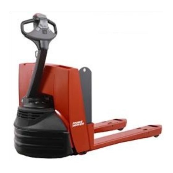
SMX45
Electric Walkie Low-Lift Pallet Truck
Effective Serial Number SMX__4533227001 - UP
Warning
Warning
Part no: 313084-000
Return
Master Service Manual
Read and observe all warnings on this unit
before operating it.
DO NOT operate this equipment unless all
factory installed guards and covers are
properly secured in place.
Front Cover
Date: December 12, 2006
Advertisement
Table of Contents
Troubleshooting

Subscribe to Our Youtube Channel
Related Manuals for prime mover smx45

Summary of Contents for prime mover smx45
- Page 1 Front Cover Master Service Manual SMX45 Electric Walkie Low-Lift Pallet Truck Effective Serial Number SMX__4533227001 - UP Warning Read and observe all warnings on this unit before operating it. Warning DO NOT operate this equipment unless all factory installed guards and covers are properly secured in place.
- Page 2 BT Prime-Mover is a trademark of BT Prime-Mover Inc., © 2006 BT Prime-Mover Inc., Muscatine, Iowa. All Rights Reserved. Return...
-
Page 3: Ordering Spare Parts
F-code Section C-code Ordering Spare Parts Version no T-code Ordering Spare Parts Supply the following information will assure prompt, efficient handling of the order: 1. Identify truck model and serial number. 2. Refer to Parts Book and locate page with the exploded diagram. - Page 4 F-code Section C-code Ordering Spare Parts Version no T-code This page is intentionally left blank. Master Service Manual 2005-07-11 Return...
-
Page 5: Standard Codes
= Component function Worksheet standard W-Code = Working code R-Code = Reason code SO-Code = Assortment F-Code List Low-Lift Pallet Truck T-Code List Model SMX45 C-Code List No Function Group C-Code Frame 0000 Motors 1000 Drive Gear / Transmission 2000... - Page 6 F-code Section C-code Standard Codes Version no T-code This page is intentionally left blank. Master Service Manual 2004-01-09 Return...
-
Page 7: Table Of Contents
Table of Contents Table of Contents Ordering Spare Parts ..................1 Standard Codes ..................... 3 Warning Symbols ..................13 Warning Levels ....................13 Prohibitory Symbols ..................14 Ordinance Symbols ....................14 Safety ......................15 General Safety ..................... 15 Battery Safety ....................20 Static Discharge Precautions .............. - Page 8 Table of Contents Jacking Truck Off The Floor ................. 58 Fork Section ......................... 59 Tractor Section ......................59 Lubricants ......................59 Standard ........................59 Cold Storage ........................ 59 Service Schedule ..................61 Planned Maintenance Schedule ................61 Planned Maintenance Procedures ............... 64 General .........................
- Page 9 Table of Contents Troubleshooting ....................76 Repair and Rebuild ....................76 Inspection Covers ..................83 Theory of Operation ..................... 83 Maintenance ......................83 Troubleshooting ....................83 Repair and Rebuild ....................83 Decals ......................85 Decal with Protective Sheet ................. 85 Decal without Protective Sheet ................
- Page 10 Table of Contents Drive Wheel Nut Inspection ..................115 Troubleshooting ....................117 Repair and Rebuild ..................... 117 Load Wheels ....................121 Theory of Operation .................... 121 Maintenance ....................... 121 Troubleshooting ....................121 Repair and Rebuild ..................... 122 Caster Wheel (Optional) ................125 Theory of Operation ....................
- Page 11 Table of Contents Shorts to Frame Test ..................... 157 Troubleshooting ....................161 Troubleshooting Flowchart ..................161 Main Harness Replacement ..................164 Operator Display and Programming ................168 Special Modes ......................168 Service Display ...................... 169 Digital Inputs/Outputs from Transistor Controller ........... 170 Transistor Controller System Mode ................
- Page 12 Table of Contents Switches ....................... 219 Theory of Operation .................... 219 Maintenance ....................... 220 Troubleshooting ....................222 Repair and Rebuild ..................... 223 Main ON/OFF Switch ....................224 Arm Angle Switches ....................224 Lift Limit Switch ......................225 Key Switch (Optional) ....................226 Horn Switch .........................
- Page 13 Table of Contents Hydraulic System ..................253 Theory of Operation .................... 253 Lift ..........................254 Lower ........................... 255 Relief Pressure ......................256 Maintenance ....................... 257 Changing Hydraulic System Fluid ................257 Hydraulic Pump Pressure Relief Valve ............... 259 Troubleshooting ....................259 Troubleshooting Chart Index ..................
- Page 14 Table of Contents This page is intentionally left blank. Master Service Manual 2004-05-17 Return...
-
Page 15: Warning Symbols
F-code Section C-code Warning Symbols Version no T-code Warning Symbols Always follow the warnings given in this Service Manual and on the truck to avoid accidents from occurring. 1. Warning Levels Warning levels Warning text is given in four levels and provide information on the risks, describe the consequences, and instruct how to avoid accidents. -
Page 16: Prohibitory Symbols
F-code Section C-code Prohibitory Symbols Version no T-code Prohibitory Symbols NO SMOKING If smoking occurs in situations where a restriction against smoking is stated, a serious accident can occur. OPEN FLAMES PROHIBITED If open flames are used in situations where open flames are prohibited, a serious accident can occur. -
Page 17: Safety
F-code Section C-code Safety Version no T-code Safety 1. General Safety Do NOT operate or work on this truck unless trained, qualified, and authorized to do so and have read the Operator’s Manual. Know the truck controls and what they do. Do NOT operate truck if it needs repair or if it is in any way unsafe. - Page 18 F-code Section C-code Safety Version no T-code Operate truck only from the position of the operator. Before working on this truck always press the red OFF (O) key on the keypad and disconnect the truck battery connector (unless this manual states otherwise.) Do NOT wear watches, rings, or jewelry when working on this truck.
- Page 19 F-code Section C-code Safety Version no T-code Follow scheduled lubrication, maintenance, inspection steps. Follow exactly the safety and repair instructions in this manual. Do NOT take “shortcuts”. Do NOT Use an open flame near the truck. Do NOT use gasoline or other flammable liquids for cleaning parts.
- Page 20 F-code Section C-code Safety Version no T-code Clean up any hydraulic fluid, oil, or grease that has leaked or spilled on the floor. Always operate and park truck indoors. Do not park truck in a cold storage area overnight. Do NOT wash truck with a hose. Master Service Manual 2004-01-09 Return...
- Page 21 F-code Section C-code Safety Version no T-code Do NOT add to or modify truck without written approval from BT Prime-Mover, Inc. Master Service Manual 2004-01-09 © BT Prime-Mover, Inc. Return...
-
Page 22: Battery Safety
F-code Section C-code Battery Safety Version no T-code Battery Safety As a battery is being charged, an explosive WARNING gas mixture forms within and around each cell. If the area is not properly ventilated, this explosive gas can remain in or around the battery for several hours after charging. - Page 23 F-code Section C-code Battery Safety Version no T-code Wear personal protective equipment to protect eyes, face, and skin when checking, handling, or filling batteries. This equipment includes goggles or face shield, rubber gloves (with or without arm shields) and a rubber apron. Make sure a shower and eyewash station are nearby in case there is an accident.
- Page 24 F-code Section C-code Battery Safety Version no T-code Keep the charger area well-ventilated to avoid hydrogen gas concentration. Press the red OFF (O) key on the keypad before disconnecting the battery from the truck at the battery connector. Do NOT break live circuits at the battery terminals. A spark often occurs at the point where a live circuit is broken.
- Page 25 F-code Section C-code Battery Safety Version no T-code Keep plugs, terminals, cables, and receptacles in good condition to avoid shorts and sparks. Cable Filler Plugs Keep filler plugs firmly in place at all times except when the electrolyte level is checked, when water is added to the cells or when the specific gravity is checked.
- Page 26 F-code Section C-code Battery Safety Version no T-code Make sure to install the correct size battery. A smaller or lighter weight battery could seriously affect truck stability. See the truck specification (data) plate for more information. Never plug a battery charger into the truck battery connector. Plug battery charger ONLY into battery connector from battery.
-
Page 27: Static Discharge Precautions
F-code Section C-code Static Discharge Precautions Version no T-code Static Discharge Precautions Electronic circuit board and devices used on the truck can be damaged by the discharge of static electricity, called electrostatic discharge. Static charges can accumulate from normal operation of the truck as well as movement or contact between non- conductive materials such as plastic bags, synthetic clothing, synthetic soles on shoes, styrofoam coffee cups, etc. - Page 28 F-code Section C-code Static Discharge Precautions Version no T-code 7. When the operator moves from any other place to the static-free station, the start-up procedure should be the same as the preparation for working at a static-free workstation. 8. “Plastic snow” polystyrene foam, peanuts, or other high-dielectric materials should never come in contact with or be used around electrostatic sensitive items, unless they have been treated with...
-
Page 29: Welding Safety
F-code Section C-code Welding Safety Version no T-code Welding Safety Flame cutting or welding on painted WARNING surfaces may produce potentially harmful fumes, smoke vapors. Prior performing flame cutting welding operations, it is recommended that the coating be removed in the vicinity where the operation(s) will be performed. - Page 30 F-code Section C-code Welding Safety Version no T-code Disconnect battery before attempting to CAUTION inspect, service or repair truck. Discharge residual charge in the transistor controller by connecting a load across the transistor controllers B+ and B- terminals (such as a contactor coil or by pressing the horn button.) •...
-
Page 31: Introduction, Service Manual
Introduction, Service Manual Version no T-code Introduction, Service Manual The information in this service manual covers model SMX45. Federal and State laws require that operators be completely trained in the safe operation of lift trucks in accordance with OHSA regulation 1910.178. - Page 32 F-code Section C-code Introduction, Service Manual Version no T-code This page is intentionally left blank. Master Service Manual 2004-01-09 Return...
-
Page 33: Contents, Section M
F-code Section C-code Contents, Section M Version no T-code Contents, Section M 1. Machine Information M1.0 GENERAL PRODUCT INFORMATION M2.0 TECHNICAL SERVICE DATA Master Service Manual 2004-01-09 © BT Prime-Mover, Inc. Return... - Page 34 F-code Section C-code Contents, Section M Version no T-code This page is intentionally left blank. Master Service Manual 2004-01-09 Return...
-
Page 35: General Product Information
The trucks lifting capacities can be found on the truck’s data plate. The SMX45 truck is equipped with a 24 volt electrical system. Speed is regulated by means of a transistor controller to provide infinite control of acceleration and speed while driving. -
Page 36: Prohibited Truck Application
(see page 36.) Metric dimensions and capacities are shown in parenthesis and have been rounded for convenience. Truck Data SMX45 Lifting capacity rated load, lb (kg) 4500 (2241) Lift height, inch (mm) 5.0 (127.0) Operating speed without load, mph (kph) 3.6 (5.8) -
Page 37: Dimensions
C-code M1.0 General Product Information Version no T-code 1.5. Dimensions The following diagram shows external dimensions for the SMX45 truck in its standard design. 68.6 inch (1742 mm) 23.0 inch (585 mm) Battery Compartment 27.0 inch 26.6 inch (685 mm) 28.0 inch... -
Page 38: Data Plate
F-code Section C-code M1.0 General Product Information Version no T-code Use only batteries that meet the following specifications: Battery Pack Dimension Specifications 24 Volt Battery Pack Amp Hour Length Width Height Max Weight Swing-out Upper Trays 26.5 inch 7.5 inch 26.45 inch 300 lbs (136 kg) with 15 amp charger... -
Page 39: Main Components
F-code Section C-code M1.0 General Product Information Version no T-code 2. Main Components 1. Steering Control Handle: The truck is to be controlled by the operator with 180 degree steering angle. The truck has the ability to right-angle stack. The brake is applied in the upper and lower position of the steering control head. - Page 40 F-code Section C-code M1.0 General Product Information Version no T-code 13. Main ON/OFF switch The main ON/OFF switch will cut off all electrical power to the control functions on the truck when pressed. 14. Travel speed / direction selection To select direction, rotate thumb controls in the direction of travel.
-
Page 41: Inch (Sae) And Metric Fasteners
F-code Section C-code M1.1 Inch (SAE) and Metric Fasteners Version no T-code Inch (SAE) and Metric Fasteners 1. Introduction Threaded fasteners such as bolts, nuts, cap screws, and studs are made to specifications that describe mechanical strength and hardness of fastener. A fastener used in a design application is selected in accordance with its specifications. -
Page 42: Nomenclature, Threads
F-code Section C-code M1.1 Inch (SAE) and Metric Fasteners Version no T-code 2. Nomenclature, Threads The thread design is specified by a series of numbers and letters for inch and metric fasteners (see figure below.) The diameter of shank of fastener is shown first in the series, e.g. M12=12 mm, M20=20 mm (1/2=1/2 inch, 3/4=3/4 inch.) The number of threads per inch is normally not shown for inch nomenclature and only UNC (Unified National Coarse) or... -
Page 43: Strength Identification
F-code Section C-code M1.1 Inch (SAE) and Metric Fasteners Version no T-code 3. Strength Identification The most common property classes for metric fasteners are 8.8 and 10.9. The property class is marked with a number on the head of the cap screw or on a nut. Property classes less then 8.8 are often not marked. - Page 44 F-code Section C-code M1.1 Inch (SAE) and Metric Fasteners Version no T-code Table 1. Bolt and Screw Designations Metric Fasteners Inch Fasteners Types of Strength Levels: Property Classes Strength Levels: SAE Grades Fasteners Markings Not Required 4.6* 4.8* 5.8* 10.9 12.9 Markings for size...
- Page 45 F-code Section C-code M1.1 Inch (SAE) and Metric Fasteners Version no T-code Table 2. Stud and Nut Designations Types of Inch Fasteners Metric Fasteners Strength Levels: SAE Grades Strength Levels: Property Classes Fasteners Markings Not Required Markings Not Required 4.6* 4.8* 5.8* 5.2*...
- Page 46 F-code Section C-code M1.1 Inch (SAE) and Metric Fasteners Version no T-code Table 3. Torque Nut Designations Inch Fasteners Types of Metric Fasteners Strength Levels: SAE Grades Strength Levels: Property Classes Fasteners All Metal Prevailing Torque Nuts All Metal Prevailing Torque Flange Nuts Master Service Manual 2004-01-12...
- Page 47 F-code Section C-code M1.1 Inch (SAE) and Metric Fasteners Version no T-code Table 4. Torque Nut with Nylon Insert Designations Types of Inch Fasteners Metric Fasteners Fasteners Strength Levels: SAE Grades Strength Levels: Property Classes Markings Not Required Nylon Insert Pre- vailing Torque Nuts Markings Not Required...
- Page 48 F-code Section C-code M1.1 Inch (SAE) and Metric Fasteners Version no T-code Table 5. Fastener Torque Values Property, Class Property, Class Property, Class 8.8* 10.9** 12.9*** Size and Pitch N•m in-lbs N•m in-lbs N•m in-lbs M5 x 0.8 44-53 62-71 8-10 71-88 M6 x 1...
-
Page 49: Truck Torque Specifications
F-code Section C-code M1.1 Inch (SAE) and Metric Fasteners Version no T-code 4. Truck Torque Specifications Description Torque Specification Drive motor end cover bolts 70.5 - 77.3 ft-lbs (95.6 - 104.8 N•m) Gear case cover mounting bolts 30 ft-lbs (42 N•m) (sealant, see page Drive wheel axle nut 55 ft-lbs (74.6 N•m) -
Page 50: Conversion Of Metric And English Units
F-code Section C-code M1.1 Inch (SAE) and Metric Fasteners Version no T-code 5. Conversion of Metric and English Units Area Multiply To Get Multiply To Get inches² 6.451 centimeters² (cm²) centimeters² 0.155 inches² (in²) feet² 0.093 meters² (m²) meters² 10.764 feet²... - Page 51 F-code Section C-code M1.1 Inch (SAE) and Metric Fasteners Version no T-code Temperature Multiply To Get Multiply To Get (Fahrenheit 0.56 Celsius (C) (Celsius x 1.8) Fahrenheit (F) -32) Torque Multiply To Get Multiply To Get inch pounds inch pound 0.113 Newton meter (N•m) Newton meter...
- Page 52 F-code Section C-code M1.1 Inch (SAE) and Metric Fasteners Version no T-code This page is intentionally left blank. Master Service Manual 2004-01-12 Return...
-
Page 53: Technical Service Data
F-code Section C-code M2.0 Technical Service Data Version no T-code Technical Service Data NOTE! When battery fully charged, performance may vary due to motor and system efficiency tolerance. Technical service data represents nominal values obtained under typical operating conditions. Specifications subject change without notice. - Page 54 F-code Section C-code M2.0 Technical Service Data Version no T-code Hydraulic Unit Power - horsepower [hp] (kilowatts [kW]) 1.9 (1.4) Duty factor 10% on 5 min. cycles Minimum brush length - inch (mm) 0.35 (9) Minimum commutator diameter - inch (mm) 1.13 (28.8) Minimum brush spring tension - ounce-force (newton) 17.98 (5)
- Page 55 F-code Section C-code M2.0 Technical Service Data Version no T-code Operating Speeds Without load - mph (kph) 3.6 (5.8) With rated load - mph (kph) 3.4 (5.5) Lifting/lowering Time Lift empty, high speed (seconds) Lift rated load, low speed (seconds) Lower with rated load, low speed (seconds) Current Readings Driving without load (amps taken at steady state)
- Page 56 F-code Section C-code M2.0 Technical Service Data Version no T-code This page is intentionally left blank. Master Service Manual 2006-08-03 Return...
-
Page 57: Contents, Section P
F-code Section C-code Contents, Section P Version no T-code Contents, Section P 1. Planned Maintenance P1.0 INTRODUCTION, MAINTENANCE P2.0 SERVICE SCHEDULE P3.0 LUBRICATION CHART P4.0 OIL AND GREASE SPECIFICATIONS Master Service Manual 2004-01-14 © BT Prime-Mover, Inc. Return... - Page 58 F-code Section C-code Contents, Section P Version no T-code This page is intentionally left blank. Master Service Manual 2004-01-14 Return...
-
Page 59: Introduction, Maintenance
F-code Section C-code P1.0 Introduction, Maintenance Version no T-code Introduction, Maintenance The schedule of maintenance and lubrication given in this section of the service manual cover up to one year’s operation of the truck. These schedules are based on hourly usage and can be adapted to suit most schedules. -
Page 60: Jacking Truck Off The Floor
F-code Section C-code P1.0 Introduction, Maintenance Version no T-code 1. Jacking Truck Off The Floor To perform maintenance that requires the truck to be lifted from the floor, observe the proper precautions as follows: 1. Lower the forks completely. Remove any load. 2. -
Page 61: Fork Section
F-code Section C-code P1.0 Introduction, Maintenance Version no T-code 1.1. Fork Section 1. Using the lift button, raise the forks to maximum height. 2. Block the fork section. The tractor section will remain on the floor. 3. Lower the forks on the blocks. 4. - Page 62 F-code Section C-code P1.0 Introduction, Maintenance Version no T-code This page is intentionally left blank. Master Service Manual 2006-08-03 Return...
-
Page 63: Service Schedule
F-code Section C-code P2.0 Service Schedule Version no T-code Service Schedule 1. Planned Maintenance Schedule WORK REQUIRED ITEM Interval in Hours 1500 Interval in Days/Weeks/Months 12 m General Check for loose hardware. Tighten if necessary. Note any unusual noise during operation Check for leaks around drive unit and hydraulic system. - Page 64 F-code Section C-code P2.0 Service Schedule Version no T-code WORK REQUIRED ITEM Interval in Hours 1500 Interval in Days/Weeks/Months 12 m 5000.8 Check operation of reverse button. 5110 Battery 5110.1 Check cleanliness and exterior conditions. 5110.2 Check the battery charge. 5110.3 Check the battery weight.
- Page 65 F-code Section C-code P2.0 Service Schedule Version no T-code 5110 5400 5111 0300 6420 5000 3550 4100 0300 6420 5700 1700 3300 3500 1700 6000 2550 Master Service Manual 2006-08-03 © BT Prime-Mover, Inc. Return...
-
Page 66: Planned Maintenance Procedures
F-code Section C-code P2.0 Service Schedule Version no T-code 2. Planned Maintenance Procedures This section describes how to perform the services listed in the Schedule of Planned Maintenance Operations. As with the “Schedule”, this section is subdivided into service intervals. 2.1. -
Page 67: Cables And Connections
F-code Section C-code P2.0 Service Schedule Version no T-code 2.1.4. Cables and Connections Tighten connections. Check all cable insulation for damage. Check that all electrical connections are clean and tight. Plug- in connectors should be unplugged and plugged back in to clean terminals. -
Page 68: Functions/Operations
F-code Section C-code P2.0 Service Schedule Version no T-code 2.2.5. Functions/Operations Test truck for the proper operation of all functions including the speed and thumb controls (arm angle switches), lift and lower functions, brakes, steering, reverser button, horn button and the main ON/OFF switch. Devices must be operational. Report any problems to the proper authorities. -
Page 69: Services Performed Every Two Months Or Every 250 Operating Hours
F-code Section C-code P2.0 Service Schedule Version no T-code 2.3. Services Performed Every Two Months or Every 250 Operating Hours The following inspections are to be made by the operator prior to each operating shift. It is the operator's responsibility to report any problems with the truck to the appropriate personnel. -
Page 70: Battery
F-code Section C-code P2.0 Service Schedule Version no T-code Check for electrical shorts to frame (see page 157.) 2.3.6. Battery Check battery mounting bolt. Check freeplay in battery mounting area. 2.3.7. Electrical Panel Clean and check electrical panel mounting to frame. Check for connections in harness connectors. -
Page 71: Hydraulic System
F-code Section C-code P2.0 Service Schedule Version no T-code 2.4.2. Hydraulic System The hydraulic system should be drained, flushed and refilled. Clean the hydraulic filters when hydraulic fluid is changed. The pressure relief valve setting should be checked. WARNING Before siphoning oil from the reservoir, make certain siphon is clean. - Page 72 F-code Section C-code P2.0 Service Schedule Version no T-code This page is intentionally left blank. Master Service Manual 2006-08-03 Return...
-
Page 73: Lubrication Chart
F-code Section C-code P3.0 Lubrication Chart Version no T-code Lubrication Chart Interval/Running Hours Lubricant Pos. No Service Point (See “Lubricants” 360 h 720 h 1440 h on page Wheel bearings Hydraulic system Drive gear Drive gear drain L= Lubrication C = Check O = Oil change Master Service Manual 2004-01-14... -
Page 74: Oil And Grease Specifications
F-code Section C-code P4.0 Oil and Grease Specifications Version no T-code Oil and Grease Specifications 1. Lubricants Lubricant Specifications Cold Storage Continuous Standard Operation Operation Down To Lubricant Down To 5° F (-15° C) Application area 32° F Intermittent (0° C) Operation Down To -13°... -
Page 75: Contents, Section S
F-code Section C-code Contents, Section S Version no T-code Contents, Section S 1. Service Instructions NO FUNCTION GROUP C-CODE FRAME 0000 MOTORS 1000 DRIVE GEAR / TRANSMISSION 2000 BRAKE / WHEEL SYSTEM 3000 STEERING SYSTEM 4000 ELECTRICAL / PNEUMATIC SYSTEM 5000 HYDRAULIC SYSTEM / CYLINDERS 6000... - Page 76 F-code Section C-code Contents, Section S Version no T-code This page is intentionally left blank. Master Service Manual 2003-10-28 Return...
-
Page 77: Frame
F-code Section C-code S0.1 0300 Frame Version no T-code Frame 1. Theory of Operation The carrier frame is the body section of the truck that contains the drive motor, drive unit, drive wheel, controls, and steering control handle (with electronic tiller arm card [ETAC.]) The lift frame is the section of the truck that contains the battery, pull rods, and load wheels, along with the hydraulic and electrical systems. -
Page 78: Troubleshooting
F-code Section C-code S0.1 0300 Frame Version no T-code 5. All bushings are to be replaced with new. 3. Troubleshooting Inspect carrier frame and lift frame for crack formation and damage. 4. Repair and Rebuild NOTE! CLEANLINESS! Perform procedures in a clean environment. - Page 79 F-code Section C-code S0.1 0300 Frame Version no T-code Truck Serial Numbers 33227001 - 34271000 Item Item Item Description Description Description Wheel fork assembly Screw Bushing Load wheel Bracket, lift limit Fork, wheel Frame, carrier Bushing Screw Screw Screw, set Link assembly, upper Pull rod assembly Bushing...
- Page 80 F-code Section C-code S0.1 0300 Frame Version no T-code Truck Serial Numbers 34271001 - Up 33 34 Master Service Manual 2006-08-03 Return...
- Page 81 F-code Section C-code S0.1 0300 Frame Version no T-code Item Item Item Description Description Description Wheel fork assembly Bracket, lift limit Load wheel Frame, carrier Screw Fork, wheel Screw Pull rod assembly Bushing Link assembly, upper Bushing Screw, set Bushing Screw Screw Fitting, grease (optional)
- Page 82 F-code Section C-code S0.1 0300 Frame Version no T-code 6. Remove truck cover(s) [see page 84.] When using compressed air, wear effective WARNING chip-guarding personal protective equipment Compressed used cleaning MUST be reduced to less than 30 psi (207 kPa). 7.
- Page 83 F-code Section C-code S0.1 0300 Frame Version no T-code Installation When using compressed air, wear effective WARNING chip-guarding personal protective equipment Compressed used cleaning MUST be reduced to less than 30 psi (207 kPa). 1. All parts should be cleaned and dried thoroughly. Metal parts should be lightly oiled prior to reassembly.
- Page 84 F-code Section C-code S0.1 0300 Frame Version no T-code 11. Turn the main ON/OFF switch to the ON position. Enter key code and press the green ON button “I” on the keypad. Test truck for proper operation before returning to service. Cylinder Retention Trucks with serial numbers 34271001 - Up are equipped with the retainer spring (33), nut (34), and washer (35, see...
-
Page 85: Inspection Covers
F-code Section C-code S0.2 0340 Inspection Covers Version no T-code Inspection Covers 1. Theory of Operation The truck covers are easily removed for access to the components. During operation of the truck, the covers must be secured to the truck. 2. - Page 86 F-code Section C-code S0.2 0340 Inspection Covers Version no T-code Item Description Clip Cover, upper Screw Cover, lower Bumper Lockwasher Screw Master Service Manual 2004-01-30 Return...
-
Page 87: Decals
F-code Section C-code S0.3 0851 Decals Version no T-code Decals Remove and replace any decals that are damaged or missing. Remove a damaged decal by using a sharp edge to peel the decal from the surface. Use caution not to scratch or damage the paint on the truck when removing the decal. - Page 88 F-code Section C-code S0.3 0851 Decals Version no T-code This page is intentionally left blank. Master Service Manual 2004-01-30 Return...
-
Page 89: Electric Motors
F-code Section C-code S1.0 1700 Electric Motors Version no T-code Electric Motors Electric motors provide power to the transmission and hydraulic systems. Motor speed and direction are controlled by the transistor controller or contactor with inputs from the operator controls. 1. -
Page 90: Troubleshooting
F-code Section C-code S1.0 1700 Electric Motors Version no T-code Each partial inspection of the motor must include: 1. Inspect the brushes for wear and for correct contact with the commutator. Record the level of wear on the brushes. This history will indicate whether a brush must be changed or if it can wait until the next inspection. -
Page 91: Repair And Rebuild
F-code Section C-code S1.0 1700 Electric Motors Version no T-code 4. Repair and Rebuild 4.1. Motor Brushes 4.1.1. Drive Motor 1. Park truck on a level surface and make sure parking brake is applied and load wheels are blocked to prevent accidental movement. 2. -
Page 92: Pump Motor
F-code Section C-code S1.0 1700 Electric Motors Version no T-code 4.1.2. Pump Motor Pump Motor Motor End Cover Brushes Brushes Figure 1-2: Pump Motor 1. The pump motor will need to be removed from the hydraulic assembly before inspecting brushes. Remove screws from motor end cover. -
Page 93: Brush Replacement
F-code Section C-code S1.0 1700 Electric Motors Version no T-code 4.1.4. Brush Replacement Do not replace just one or two brushes. When brush service is required on the motor, lift brush spring over holding bracket before removing brush (see the following drawing.) Put Spring In This Position For Brush Removal Figure 1-3: Motor Brush Removal... -
Page 94: Pump Motor
F-code Section C-code S1.0 1700 Electric Motors Version no T-code 4.2. Pump Motor Pump Motor Mounting Cylinder Assembly Contactor Pump Motor Reservoir Item Description Pump Motor Assembly Kit, brush and spring Bearing 4.2.1. Removal 1. Park truck on a level surface and make sure parking brake is applied and load wheels are blocked to prevent accidental movement. -
Page 95: Installation
F-code Section C-code S1.0 1700 Electric Motors Version no T-code 7. Disconnect hydraulic motor power cables and mark their positions. Disconnect contactor wiring, noting their position. 8. Remove screws securing hydraulic pump and motor assembly to frame. Remove pump/motor assembly from truck. 9. -
Page 96: Drive Motor
F-code Section C-code S1.0 1700 Electric Motors Version no T-code 4.3. Drive Motor 17 16 “EE” Master Service Manual 2006-08-04 Return... - Page 97 F-code Section C-code S1.0 1700 Electric Motors Version no T-code Item No. Description Item No. Description Ring, retainer Screw Gear Cover Plate, brush Case Spring Terminal Brush Screw Ring, retainer Washer Bearing Field Lockwasher Isolator Screw Bearing Shoe, pole Shim Washer Seal Screw...
-
Page 98: Drive Motor
F-code Section C-code S1.0 1700 Electric Motors Version no T-code 4.4. Drive Motor Drive Motor Mounting Steering Bearing Carrier Frame Steering Control Head Drive Wheel Drive Motor Transmission Assembly Master Service Manual 2006-08-04 Return... -
Page 99: Removal
F-code Section C-code S1.0 1700 Electric Motors Version no T-code 4.4.1. Removal There is no brake on the truck when the WARNING drive motor removed from transmission assembly. Block all wheels to reduce the risk of truck movement. 1. Park the truck on a level surface and make sure parking brake is applied and load wheels are blocked to prevent accidental movement. - Page 100 F-code Section C-code S1.0 1700 Electric Motors Version no T-code 7. Connect the battery connector to the truck. 8. Turn the main ON/OFF switch to the ON position. Enter key code and press the green ON button “I” on the keypad. 9.
-
Page 101: Transmission
F-code Section C-code S2.0 2550 Transmission Version no T-code Transmission 1. Theory of Operation This transmission is of the double reduction gear type. The gears are a combination of helical and straight cut gears for strength and low noise. The final drive gear is mounted on opposing tapered roller bearings. -
Page 102: Troubleshooting
F-code Section C-code S2.0 2550 Transmission Version no T-code 6. Fill transmission case with oil (see page through plug opening in transmission cover. 3. Troubleshooting Because of the uncomplicated nature of the transmission, troubleshooting is limited to identifying problems if they are mechanical or electrical in nature. - Page 103 F-code Section C-code S2.0 2550 Transmission Version no T-code Transmission Transmission Mounting Mounting Item No. Description Screw Cushion, upstop Screw Mount, stem Screw Clip Stem, handle Screw, set Steering control head Washer Bushing Spring Sleeve Washer Screw Lockwasher Carrier frame Drive unit Drive motor Brake assembly...
- Page 104 F-code Section C-code S2.0 2550 Transmission Version no T-code 14 15 Transmission Assembly Item No. Description Item No. Description Item No. Description Stud Ring, retainer Bearing Axle Gear Gear Seal Cover Bearing Bearing Plug Retainer ring Spacer Vent Gear O ring Screw Plug Lockwasher...
- Page 105 F-code Section C-code S2.0 2550 Transmission Version no T-code Removal There is no brake on the truck when the WARNING drive motor removed from transmission assembly. Block all wheels to reduce the risk of truck movement. NOTE! Call-outs in the following procedure refer to illustration on page 101.
- Page 106 F-code Section C-code S2.0 2550 Transmission Version no T-code Wiring Harness Connector Arm Angle Switches Figure 2-3: Handle Harness 8. Disconnect arm angle switches. 9. Remove screws from stem mount securing steering control handle assembly to the drive unit assembly. 10.
- Page 107 F-code Section C-code S2.0 2550 Transmission Version no T-code Disassembly NOTE! Call-outs in the following procedures refer to illustration on page 102. Thoroughly clean the outside of the gear case with a non- corrosive cleaning fluid. Dry all parts and proceed as follows. 1.
- Page 108 F-code Section C-code S2.0 2550 Transmission Version no T-code 5. Install second stage gear set (10) and (17). NOTE! The seal must be installed correctly with its open side and seal ring positioned towards the bearing. Ensure the motor end cap is installed before proceeding to the next step.
- Page 109 F-code Section C-code S2.0 2550 Transmission Version no T-code 8. Ensure drive unit contains the correct gear oil level (see page 72.) Install fill/level plug. 9. With the truck still blocked and drive unit off the ground, connect the truck to a battery. (Do not install battery on the truck at this time.) 10.
- Page 110 F-code Section C-code S2.0 2550 Transmission Version no T-code This page is intentionally left blank. Master Service Manual 2006-08-04 Return...
-
Page 111: Parking Brake System
F-code Section C-code S3.0 3300 Parking Brake System Version no T-code Parking Brake System 1. Theory of Operation The parking brake is an electrically released disk brake mounted on the drive motor armature for increased braking force through the transmission. The parking brake is applied when the control handle is returned to the upper rest position or in the bottom 8 degrees of the operating range. - Page 112 F-code Section C-code S3.0 3300 Parking Brake System Version no T-code When the steering control handle is in the upper rest position, the parking brake is engaged. When the handle is within 6 to 41 degrees of the upper rest position and travel request is made, the brake disengages, allowing the truck to operate in slow speed.
-
Page 113: Maintenance
F-code Section C-code S3.0 3300 Parking Brake System Version no T-code 2. Maintenance See “Planned Maintenance Schedule” on page 61. 2.1. Mechanical Brake Release If the brake can not be mechanically released, perform the following procedures: 1. Park truck on a level surface and load wheels are Mounting Bolts blocked to prevent accidental movement. -
Page 114: Troubleshooting
F-code Section C-code S3.0 3300 Parking Brake System Version no T-code 6. Loosen assembly mounting bolts on brake. 7. Turn the adjusting screws while checking the air gap at several points with a 0.008 to 0.014 inch (0.2 to 0.36 mm) feeler gauge. 8. -
Page 115: Repair And Rebuild
F-code Section C-code S3.0 3300 Parking Brake System Version no T-code 4. Repair and Rebuild Item Item Description Description Transmission assembly Disk Brake assembly Coil Flange, friction Screw Retaining ring Removal 1. Park truck on a level surface and make sure parking brake is applied and load wheels are blocked to prevent accidental movement. - Page 116 F-code Section C-code S3.0 3300 Parking Brake System Version no T-code 4. Remove truck cover(s) [see page 84.] 5. Loosen and remove mounting bolts (7). Remove brake coil (6) assembly. 6. Remove friction disk (5) from hub (4). 7. Remove retaining ring (8) from hub (4). 8.
-
Page 117: Drive Wheel
F-code Section C-code S3.1 3530 Drive Wheel Version no T-code Drive Wheel 1. Theory of Operation The drive wheel is mounted on the transmission drive axle. The drive wheel is part of the drive unit assembly. Drive Wheel Specifications 10 inch X 5 inch (255 X 125 mm) 2. - Page 118 F-code Section C-code S3.1 3530 Drive Wheel Version no T-code NOTE! The installation procedure of the studs, wheel and lug nuts must be completed in less than 0.50 hour to ensure the thread locking compound does not start to set up before the installation is complete.
-
Page 119: Troubleshooting
F-code Section C-code S3.1 3530 Drive Wheel Version no T-code 3. Troubleshooting Inspect wheel and tire for wear and damage. Trash that is wrapped around the wheel and axle will cause premature tire wear and bearing damage. The floors should be kept clean of trash to reduce risk of damage to wheel and tire. - Page 120 F-code Section C-code S3.1 3530 Drive Wheel Version no T-code 2. Press red OFF button “O” on the keypad. Depress main ON/OFF switch to the OFF position. 3. Disconnect the battery connector from the truck. 4. Remove truck cover(s) and bumper (see page 84.) 5.
- Page 121 F-code Section C-code S3.1 3530 Drive Wheel Version no T-code Tire Pressing Procedure 1. Check the inside surface of metal insert on the new tire. Remove any scaling or rust with sandpaper. Clean the inside of metal insert and lubricate with a soap solution.
- Page 122 F-code Section C-code S3.1 3530 Drive Wheel Version no T-code Any misalignment of tire and hub while tire CAUTION is being pressed onto hub can cause damage to hub. For this reason, chamfers have been provided on the outside edge of hub and on the end of the inside diameter of tire’s metal insert.
-
Page 123: Load Wheels
F-code Section C-code S3.2 3550 Load Wheels Version no T-code Load Wheels 1. Theory of Operation The load wheels are mounted on the pallet forks to support the rated load at the forks fully raised height. Load wheels contain sealed bearings on both sides. Load Wheel Specifications 3.25 inch X 4.50 inch (82 X 115 mm) 2. -
Page 124: Repair And Rebuild
F-code Section C-code S3.2 3550 Load Wheels Version no T-code 4. Repair and Rebuild Item Description Bearing Wheel, load Removal 1. Park the truck on a level surface. 2. Lift forks to maximum height and block (see page 58.) 3. Press red OFF button “O” on the keypad. Depress main ON/OFF switch to the OFF position. - Page 125 F-code Section C-code S3.2 3550 Load Wheels Version no T-code 6. Drive the axle out of the load arm casing with a hammer and brass drift pin. 7. Push the wheel out. 8. If bearings are to be reused, insert a brass drift pin into each of the load wheel and knock bearings out.
- Page 126 F-code Section C-code S3.2 3550 Load Wheels Version no T-code This page is intentionally left blank. Master Service Manual 2006-08-04 Return...
-
Page 127: Caster Wheel (Optional)
F-code Section C-code S3.3 3560 Caster Wheel (Optional) Version no T-code Caster Wheel (Optional) 1. Theory of Operation The caster assembly is mounted on the truck bumper to provide truck maximum stability. 2. Maintenance Normal maintenance includes lubricating the grease fittings on the caster assembly periodically. -
Page 128: Troubleshooting
F-code Section C-code S3.3 3560 Caster Wheel (Optional) Version no T-code 3. Troubleshooting Lubricate caster swivel as necessary. 4. Repair and Rebuild Master Service Manual 2005-07-11 Return... - Page 129 F-code Section C-code S3.3 3560 Caster Wheel (Optional) Version no T-code Item Item Item Description Description Description Caster Assembly Bearing, thrust Wheel Fitting, grease Screw Washer assembly Screw Block, torsion Bearing cup Housing Plate Washer, flat O Ring Washer, thrust Bearing Removal 1.
- Page 130 F-code Section C-code S3.3 3560 Caster Wheel (Optional) Version no T-code Installation When using compressed air, wear effective WARNING chip-guarding personal protective equipment. Compressed air used for cleaning MUST be reduced to less than 30 psi (207 kPa). 1. All parts should be cleaned and dried thoroughly. Metal parts should be lightly oiled prior to reassembly.
-
Page 131: Steering Control Handle
F-code Section C-code S4.0 4100 Steering Control Handle Version no T-code Steering Control Handle 1. Theory of Operation The steering control head fastens to the handle stem and mounts on the carrier frame. Ease of operator steering and the ability to right-angle stack is provided by the handle assembly. -
Page 132: Repair And Rebuild
F-code Section C-code S4.0 4100 Steering Control Handle Version no T-code 4. Repair and Rebuild Master Service Manual 2006-08-07 Return... - Page 133 F-code Section C-code S4.0 4100 Steering Control Handle Version no T-code Item Item Description Description Screw Sleeve Cushion, upstop Washer, plastic Screw Screw Mount, stem Lockwasher Screw Carrier frame Clip Drive unit Stem, handle Drive motor Screw, set Brake assembly Steering control head Transmission assembly Washer...
- Page 134 F-code Section C-code S4.0 4100 Steering Control Handle Version no T-code Cover Screw Figure 4-1: Control Handle Cover 6. Lift cover (4) off assembly and lay to one side. Wiring Harness Connector Arm Angle Switches Figure 4-2: Wiring Harness NOTE! Make note locations of cable ties on handle harness before disconnecting wiring.
- Page 135 F-code Section C-code S4.0 4100 Steering Control Handle Version no T-code 10. Inspect stem harness and washer (10), bushing (11), spring (12), sleeve (13), and washer (14) for excessive wear. Replace if necessary. Installation NOTE! Make sure brake release cam assembly is in the correct position before proceeding with installation procedures.
- Page 136 F-code Section C-code S4.0 4100 Steering Control Handle Version no T-code 8. Turn main ON/OFF switch to the “On” position and enter key code and press green ON button “I” on the keypad. 9. Test operation of all steering control handle functions before returning to service.
-
Page 137: Steering Control Head
F-code Section C-code S4.1 4100 Steering Control Head Version no T-code Steering Control Head 1. Theory of Operation The steering control head is mounted to the steering control handle. For functions of the control handle assembly see “Changing Driver Accessible Parameters (P)”... -
Page 138: Repair And Rebuild
F-code Section C-code S4.1 4100 Steering Control Head Version no T-code 4. Repair and Rebuild Master Service Manual 2006-08-07 Return... - Page 139 F-code Section C-code S4.1 4100 Steering Control Head Version no T-code Item Item Description Description Screw Spring Plate Screw Handle Screw Screw Tie, cable Cover (option) Screw Pad, key Tie, cable Screw Thumb control assembly Screw Screw Relief, strain Washer Plate Switch, right Handle assembly, control...
- Page 140 F-code Section C-code S4.1 4100 Steering Control Head Version no T-code Removal 1. Park truck on a level surface and make sure parking brake is applied and load wheels are blocked to prevent accidental movement. 2. Release pressure in hydraulic system by pressing the lowering button on steering control head.
- Page 141 F-code Section C-code S4.1 4100 Steering Control Head Version no T-code Installation NOTE! Place finger between housing (21) and reverser button (14) to hold right rocker (33) in place while installing housing (21). 1. Install thumb wheel assembly (30). 2. Install lift/lower button (44). 3.
- Page 142 F-code Section C-code S4.1 4100 Steering Control Head Version no T-code This page is intentionally left blank. Master Service Manual 2006-08-07 Return...
-
Page 143: Steering Bearing
F-code Section C-code S4.2 4180 Steering Bearing Version no T-code Steering Bearing 1. Theory of Operation The steering bearing is part of the drive unit assembly. The vertical and horizontal loads are carried by the steering bearing. 2. Maintenance Inspect for wear or damage. 3. -
Page 144: Repair And Rebuild
F-code Section C-code S4.2 4180 Steering Bearing Version no T-code 4. Repair and Rebuild Item No. Description Screw Lockwasher Bearing Stop, steering Transmission assembly Master Service Manual 2004-02-13 Return... - Page 145 F-code Section C-code S4.2 4180 Steering Bearing Version no T-code The steering bearing can not be repaired or rebuilt. Replace steering bearing with new as necessary. Removal 1. Park truck on a level surface and make sure parking brake is applied and load wheels are blocked to prevent accidental movement.
- Page 146 F-code Section C-code S4.2 4180 Steering Bearing Version no T-code Installation 1. Install bearing secure with lockwashers (2) and screws (1) on transmission. 2. Install transmission (see page 106.) 3. Connect all electrical connections. 4. Refill transmission with fluid as needed (see page 72.) 5.
-
Page 147: Electrical Functions
F-code Section C-code S5.0 5000 Electrical Functions Version no T-code Electrical Functions 1. Theory of Operation The travel control system on the truck is electrically controlled and monitored. The lift/lower systems are electrically controlled and hydraulically operated. All circuits are protected against overload with automatic resetting circuit breakers. -
Page 148: Battery Plugged In With Keypad
F-code Section C-code S5.0 5000 Electrical Functions Version no T-code 1.1. Battery Plugged In With Keypad With the battery connected to the truck, wire number 1 connects battery voltage to the positive side of the main contactor (K10), control fuse (F50), positive of the key switch jumper, electronic tiller arm card (ETAC) [A2] and positive side of resistor (PTC R1.) From resistor (PTC R1), a voltage of 1.0 to 1.5 volts less than battery voltage is provided to fuse... -
Page 149: Battery Plugged In With Key Switch
F-code Section C-code S5.0 5000 Electrical Functions Version no T-code 1.2. Battery Plugged In With Key Switch With the battery connected to the truck, wire number 1 connects battery voltage to the positive side of the main contactor (K10), control fuse (F50), positive side of the key switch and positive side of resistor (PTC R1.) From the resistor (PTC R1), a voltage of 1.0 to 1.5 volts less than the battery voltage is provided to fuse F51 and positive side of... -
Page 150: Main On/Off Switch/Keypad On
F-code Section C-code S5.0 5000 Electrical Functions Version no T-code 1.3. Main ON/OFF Switch/Keypad ON When the switches on wire number 22 connects to the battery voltage to the ETAC (A2) pin J11-1, this powers up the ETAC (A2) for start of communication to the transistor controller (A1). - Page 151 F-code Section C-code S5.0 5000 Electrical Functions Version no T-code This page is intentionally left blank. Master Service Manual 2006-12-12 © BT Prime-Mover, Inc. Return...
-
Page 152: Travel, Low Speed
F-code Section C-code S5.0 5000 Electrical Functions Version no T-code 1.4. Travel, Low Speed When the steering control handle is within 6 to 41 degrees of the upper rest position and the thumb controls are rotated from neutral, the travel signal is detected via hall effect sensors. - Page 153 F-code Section C-code S5.0 5000 Electrical Functions Version no T-code Travel Low Speed Pressure Oil Symbol Designation Symbol Designation Drive Transistor Controller Drive Motor Return Oil Electronic Tiller Arm Card Transistor Controller Pump Motor Keypad/Tiller Arm Circuit Fuse S18-1 Horn Switch B+ Circuit Main Control Fuse S18-2...
-
Page 154: Travel, High Speed
F-code Section C-code S5.0 5000 Electrical Functions Version no T-code 1.5. Travel, High Speed When the steering control handle is between 41 to 79 degrees from the upper rest position, the ETAC (A2) verifies that both arm angle switch (S24) and arm angle switch (S25) are engaged for high speed travel mode. -
Page 155: Reverser
F-code Section C-code S5.0 5000 Electrical Functions Version no T-code 1.6. Reverser When the reverser button is activated with the steering Pressure Oil control handle lowered in the travel mode, the control system Return Oil provides an immediate forks-first direction travel instruction. Reverse signal is converted into a forks-first travel instruction B+ Circuit transmitted via the CAN to the transistor controller. -
Page 156: Lift
F-code Section C-code S5.0 5000 Electrical Functions Version no T-code 1.7. Lift When the lift button is pressed, the transistor controller provides a negative pin J5-4 to the main contactor coil (K10), closing the main contactor (K10) to the main contactor relay (K4). -
Page 157: Lower
F-code Section C-code S5.0 5000 Electrical Functions Version no T-code 1.8. Lower When the lower button is pressed, the transistor controller provides a negative pin J5-4 to the main contactor coil (K10), closing the main contactor (K10) to the main contactor relay (K4). -
Page 158: Maintenance
F-code Section C-code S5.0 5000 Electrical Functions Version no T-code 2. Maintenance Connections must be kept clean and tight. The electrical components should be protected from moisture. If the truck is equipped with cold storage, or corrosive environment application package, then the di-electric compound (part number 302249-000) in the plug-in connectors should be renewed periodically. -
Page 159: Shorts To Frame Test
F-code Section C-code S5.0 5000 Electrical Functions Version no T-code switching the battery voltage to the motor on and off very quickly. Overtemperature. Overtemperature transistor controller is from 185 degrees F (85 degrees C) and above. At overtemperature, the drive current limit is linearly decreased from full set current down to zero. - Page 160 F-code Section C-code S5.0 5000 Electrical Functions Version no T-code • Motor brush leads touching housing • Insulation breakdown • Bare wires • Pinched wiring harness • Circuit cards improperly mounted Shorts to frame can occur at numerous locations on truck including the following: •...
- Page 161 F-code Section C-code S5.0 5000 Electrical Functions Version no T-code • Positive (+) lead to an unpainted, grounded surface on the truck frame. The voltmeter must show no more than 3V. 4. If a reading of 3V or more is received in the previous steps 2 or 3, proceed as follows: a.
- Page 162 F-code Section C-code S5.0 5000 Electrical Functions Version no T-code 7. To find the cause of the low resistance, disconnect the power cables from each motor or major subassembly one at a time, to determine if that item is causing the low resistance. Master Service Manual 2006-12-12 Return...
-
Page 163: Troubleshooting
F-code Section C-code S5.0 5000 Electrical Functions Version no T-code 3. Troubleshooting 3.1. Troubleshooting Flowchart Troubleshooting Truck Fault Code Find Code (see page 181) Transistor Controller Error Code Find Code (see page 246) Yes, Traction/Overall Check Troubleshooting Go to charts Chart (see page... - Page 164 F-code Section C-code S5.0 5000 Electrical Functions Version no T-code Troubleshooting can be broken down into two sections: (1) mechanical and (2) electrical circuits. Electrical circuits can be further broken down into control circuit and power circuit. Many hours of troubleshooting time can be saved by knowing the exact operational symptoms.
- Page 165 F-code Section C-code S5.0 5000 Electrical Functions Version no T-code 6° 40° 33° 8° Figure 5-1: Operating Range of Control Handle After the final troubleshooting test is completed, the truck should be repaired and operating properly. If it is not, then verify test results and possibly re-evaluate the failure symptoms.
-
Page 166: Main Harness Replacement
F-code Section C-code S5.0 5000 Electrical Functions Version no T-code 3.2. Main Harness Replacement Before removal of harness, document wire NOTE! to terminal connections for main harness. Control Wires/ Wire Guard Power Cables on Left Side Figure 5-2: Terminal Block 1. - Page 167 F-code Section C-code S5.0 5000 Electrical Functions Version no T-code 6. Remove the stem mount (see page 103) and stem handle as an assembly from the transmission (see Figure 5-3.) Remove the old harness from the truck (see page 192.) Upstop Stem Mount...
- Page 168 F-code Section C-code S5.0 5000 Electrical Functions Version no T-code 11. Position cables and wires as shown in see Figure 5-3 on page 165. 12. Correctly orient the wire guards and power wires through the transmission as shown in Figure 5-4.
- Page 169 F-code Section C-code S5.0 5000 Electrical Functions Version no T-code 15. Refer to see Figure 5-3 on page 165 when installing ring terminals. Install ring terminal and secure middle nut and torque to 79 in-lbs (8.9 N•m). Install ring terminal and secure outer nut, making sure wire is out of the way, before torquing outer nut to 79 in-lbs (8.9 N•m).
-
Page 170: Operator Display And Programming
F-code Section C-code S5.0 5000 Electrical Functions Version no T-code 3.3. Operator Display and Programming The display is located on the top of the steering control handle arm and displays the operator and machine-specific register. A - Numerical Field B - Hour Meter Indicator C - Parameter Control D - Battery Indicator E - Error Indicator... -
Page 171: Service Display
F-code Section C-code S5.0 5000 Electrical Functions Version no T-code parameter number display. All driver parameters and drivers are cycled through before Service Parameters, 0 = 10th driver.) • (P)art (n)umbers: use thumb control to scroll through the following: • (S)oftware (P)art (n)umber •... -
Page 172: Digital Inputs/Outputs From Transistor Controller
F-code Section C-code S5.0 5000 Electrical Functions Version no T-code 3.3.3. Digital Inputs/Outputs from Transistor Controller Digit Segment Function III IV Input (J5-14): Arm angle B – see below Input (J5-15): Lift limit Input (J5-12): Arm angle A – see below Input (J5-2): Lower valve (lit if valve present &... -
Page 173: Transistor Controller System Mode
F-code Section C-code S5.0 5000 Electrical Functions Version no T-code 3.3.4. Transistor Controller System Mode The transistor controller system mode is used only in special cases. Status Comment Motor drive, plug or active neutral braking Field reversal (transitional) Disable (major fault, such as severe overvoltage) Regen Regen taper (transitional) No activity: main contactor open because no output... -
Page 174: Changing Driver Accessible Parameters (P)
F-code Section C-code S5.0 5000 Electrical Functions Version no T-code 3.4. Changing Driver Accessible Parameters (P) Modify specific truck parameters will WARNING change the driving characteristics of the truck. 1. Enter special truck mode until “P” is displayed. The parameter control indicator is illuminated (see page 168.) 2. - Page 175 F-code Section C-code S5.0 5000 Electrical Functions Version no T-code The parameter change is complete. The next time the truck is started, the new parameter will be in effect. All parameters can be viewed, however, not all parameters can be changed. Truck NOTE! parameters may or may not be accessed, depending on the value of parameter 39...
-
Page 176: Changing Service Parameters
F-code Section C-code S5.0 5000 Electrical Functions Version no T-code 3.5. Changing Service Parameters A service key is required to change service NOTE! parameters. 1. Connect the service key at J41. With service key connected, the truck does NOTE! not power ON using the keypad or key switch. - Page 177 F-code Section C-code S5.0 5000 Electrical Functions Version no T-code If display/access for a service parameter is required, it is faster to initially rotate the thumb control away from the forks (go backwards through parameters/drivers.) The parameter number displays briefly, then if the thumb control is not rotated further the parameter value is displayed.
-
Page 178: Parameter Description
F-code Section C-code S5.0 5000 Electrical Functions Version no T-code 3.5.1. Parameter Description Parameter 1 Maximum speed value sent to transistor controller while in Slow mode except during turtle torque (gives torque boost if high load is encountered.) Parameter 2 Reduces speed value sent from the Electronic Tiller Arm Card (ETAC) to the transistor controller while in Fast mode (all throttle positions.) - Page 179 F-code Section C-code S5.0 5000 Electrical Functions Version no T-code • With the battery connected to the truck, service key connected, main ON/OFF switch turned to the ON position, press and hold down the horn button. • Enter key code and press “I” or turn on key switch. •...
- Page 180 F-code Section C-code S5.0 5000 Electrical Functions Version no T-code Parameter 14 Defines speed at low throttle positions. A negative number enhances low speed maneuverability. A positive number makes the truck more responsive. Parameter 20 Choose the hourmeter to display. •...
-
Page 181: Operating Parameter Programming
F-code Section C-code S5.0 5000 Electrical Functions Version no T-code Parameter 39 Determines whether the truck has a key switch or keypad and what access level service personnel will have to the driver parameters. This parameter is adjustable as follows: •... -
Page 182: Error Codes (E)
F-code Section C-code S5.0 5000 Electrical Functions Version no T-code 3.6. Error Codes (E) When an error occurs on the truck, a code is displayed (see page 181.) 3.6.1. Error Code History To access the error code history, proceed as follows: 1. -
Page 183: Truck Fault Codes
F-code Section C-code S5.0 5000 Electrical Functions Version no T-code 3.6.2. Truck Fault Codes Caution fault codes 0-49 are not logged. C codes 50-99 are logged. Code C14 - Arm Angle Reference Warning Reason Steering control handle was not in up position at power ON or after the truck has not been used for a time. Performance Limits Travel is not allowed until code is cleared. - Page 184 F-code Section C-code S5.0 5000 Electrical Functions Version no T-code Code C28 - Main ON/OFF Switch Warning Reason Transistor controller could not be reset via the CAN-bus at power ON or transistor controller reports main ON/ OFF switch is open. Performance Limits Truck functions are not allowed after code has been set.
- Page 185 F-code Section C-code S5.0 5000 Electrical Functions Version no T-code Code C42 - Battery Overvoltage Warning Reason Voltage at transistor controller B+ connection over 30V. Performance Limits Truck functions are allowed unless the voltage was above 34V, in which case the truck must be restarted (error 142, see page 186, may be displayed.)
- Page 186 F-code Section C-code S5.0 5000 Electrical Functions Version no T-code Fault codes 100 and over are logged. The log can contain multiple faults with the same number code. Throttle is not allowed, outputs are off (brake is mechanically NOTE! applied), and main contactor is dropped. Code is cleared when problem is resolved and truck is turned OFF and back ON (unless otherwise noted.)
- Page 187 F-code Section C-code S5.0 5000 Electrical Functions Version no T-code Code E108 - Contactor Welded or Missing Reason Main contactor tips welded or missing. Possible Causes Main contactor tips welded. with corrective Open or short circuit in contactor circuit. actions/checks Check contactor, wiring (coil) and cabling.
- Page 188 F-code Section C-code S5.0 5000 Electrical Functions Version no T-code Code E142 - Transistor Controller Disable Error Reason Transistor controller detected a major fault. Possible Causes Severe overvoltage (especially at main contactor close.) with corrective Check for proper voltage. actions/checks High current at digital input.
- Page 189 F-code Section C-code S5.0 5000 Electrical Functions Version no T-code Code E160 - Error In Reversing Circuit Reason ETAC detected problem with the throttle position sensors, including the sensor used to initiate reversing. Also see code 20 on page 181. Possible Causes Bad ETAC.
-
Page 190: Troubleshooting Chart Index
F-code Section C-code S5.0 5000 Electrical Functions Version no T-code 3.7. Troubleshooting Chart Index 3.7.1. Travel (Forward / Rearward) System 1. No travel in either direction, lift/lower okay (Code E106, Digital output or field overcurrent.) 2. No travel in either direction, lift/lower okay (Code E201 M-error.) 3. -
Page 191: Troubleshooting Charts
F-code Section C-code S5.0 5000 Electrical Functions Version no T-code 3.8. Troubleshooting Charts The following troubleshooting charts describe a course of testing and repair for each problem listed. If the given test is NOT successful, perform the repair listed with the test. If the given test IS successful, go to the next test or follow the special instructions given. - Page 192 F-code Section C-code S5.0 5000 Electrical Functions Version no T-code 4. Slow travel, lift/lower okay. No fault codes. Possible Cause Remedy Battery problems Replace battery with fully-charged good battery. Transistor controller ETAC Verify programming. If changed, reset programming. programming changed Binding drive wheel...
- Page 193 F-code Section C-code S5.0 5000 Electrical Functions Version no T-code 7. Slow or no travel (Code C43 (see page 183), Transistor controller thermal cutback.) Possible Cause Remedy Battery problems Verify a correct, fully-charged good battery (24V) is installed in truck. Binding load wheel(s) Make sure load wheels rotate freely, If not repair or replace (see page...
- Page 194 F-code Section C-code S5.0 5000 Electrical Functions Version no T-code Other Possible Troubleshooting Issues 1. Green and red LEDs on keypad do not light when a button on the keypad is pushed (keypad option only.) Possible Cause Remedy Open circuit of wires that power ETAC Check control wires, especially wires 1, 20, and 22 (red in steering control arm cable) and 40 (black in steering control arm cable.) Bad connectors...
- Page 195 F-code Section C-code S5.0 5000 Electrical Functions Version no T-code Main Harness Contactor Contactor Panel Assembly Power Circuit Cable Breaker Lift Limit Switch Steering Control Handle Harness Hydraulic Relay System 10 Amp Transmission Fuse Assembly Power Cables Power Cables Master Service Manual 2006-12-12 ©...
-
Page 196: Electrical Schematic 1(2)
F-code Section C-code S5.0 5000 Electrical Functions Version no T-code Electrical Schematic 1(2) Master Service Manual 2006-12-12 Return... -
Page 197: Electrical Schematic 2(2)
F-code Section C-code S5.0 5000 Electrical Functions Version no T-code Electrical Schematic 2(2) Master Service Manual 2006-12-12 © BT Prime-Mover, Inc. Return... - Page 198 F-code Section C-code S5.0 5000 Electrical Functions Version no T-code Electrical Legend Symbol Description Function Remark Transistor controller Drive motor Transistor controller Electronic Tiller Arm Card E.T.A.C. A2-S1 to A2-S9 Speed Ref Value Electronic Tiller Arm Card A2-S10 to A2-S18 Speed Ref Value Electronic Tiller Arm Card A2-S17...
- Page 199 F-code Section C-code S5.0 5000 Electrical Functions Version no T-code Electrical Graphics Graphic Description Graphic Description Battery Brake (coil) Contactor Diode Main On/Off Fuse Switch Inductive sensor Horn (normally closed) Inductive sensor (normally open) Key switch Magnet switch Magnet switch (normally closed) (normally open) Motor...
- Page 200 F-code Section C-code S5.0 5000 Electrical Functions Version no T-code Electrical Graphics Graphic Description Graphic Description Push button switch Push button switch (normally closed) (normally open) Resistor Switch Switch Switch (normally closed) (normally open) Valve Master Service Manual 2006-12-12 Return...
-
Page 201: Battery
F-code Section C-code S5.1 5110 Battery Version no T-code Battery 1. Theory of Operation Check the truck’s data plate for the weight of the battery required for the truck. Contact your local battery supplier for the purchase of a proper voltage battery. A 24 volt battery may not be supplied with the truck. -
Page 202: Exterior Cleaning
F-code Section C-code S5.1 5110 Battery Version no T-code material handled. If cells are overfilled and electrolyte collects on the covers, the following occurs: 1. The top of the battery becomes wet and stays wet, since the acid in the electrolyte does not evaporate. -
Page 203: Storage
F-code Section C-code S5.1 5110 Battery Version no T-code Read, understand, and follow procedures, recommendations and specifications available by the battery and battery charger supplier. NEVER plug the battery charger into the CAUTION truck. This will severely damage the truck’s electrical system. -
Page 204: History Record
F-code Section C-code S5.1 5110 Battery Version no T-code 2.5. History Record A battery record system is essential because battery failure can cause production slowdowns and increased battery operating costs. A properly supervised record system can detect and call attention to such operating irregularities as: •... -
Page 205: Repair And Rebuild
F-code Section C-code S5.1 5110 Battery Version no T-code 4. Repair and Rebuild Contact your local battery supplier for replacements or rebuilds. Removal 1. Park truck on a level surface and make sure parking brake is applied and load wheels are blocked to prevent accidental movement. - Page 206 F-code Section C-code S5.1 5110 Battery Version no T-code This page is intentionally left blank. Master Service Manual 2006-08-08 Return...
-
Page 207: Swing Out Battery Pack
F-code Section C-code S5.2 5110 Swing Out Battery Pack Version no T-code Swing Out Battery Pack 1. Theory of Operation The truck may be equipped with a multiple battery pack, or a maintenance-free battery and charger. 2. Maintenance Battery electrolyte is a solution of sulfuric WARNING acid and water. - Page 208 F-code Section C-code S5.2 5110 Swing Out Battery Pack Version no T-code Any cell that is different by more then 20 points indicates a suspect battery. b. Volts per cell, open circuit, before and after charging. Acceptable values: Dead battery - 1.9 v/cell Fully charged - 2.2 v/cell c.
- Page 209 F-code Section C-code S5.2 5110 Swing Out Battery Pack Version no T-code NOTE! If the AC power fuse blows or the DC 1 x circuit breaker trips, check for reverse polarity of the battery connection. a. Open circuit voltage test. With batteries disconnected and the charger turned on, the DC output voltage should be 1-1/2 times the rated DC voltage.
- Page 210 F-code Section C-code S5.2 5110 Swing Out Battery Pack Version no T-code Before checking components disconnect WARNING AC power supply, unplug batteries, and discharge capacitor with an insulated screwdriver. All tests should be made with the charger disconnected unless otherwise stated.
- Page 211 F-code Section C-code S5.2 5110 Swing Out Battery Pack Version no T-code On a good capacitor, the needle will deflect to the right (low resistance) and then deflect back to the left (high resistance) each time the meter leads are reversed. On a shorted capacitor, the needle will deflect to the right (low resistance) and remain there.
-
Page 212: Troubleshooting
F-code Section C-code S5.2 5110 Swing Out Battery Pack Version no T-code that it is comparable to the original batteries. Automotive type batteries will not function properly in this application. b. Excessive battery temperatures causing suppressed battery voltage. Allow batteries to cool. c. - Page 213 F-code Section C-code S5.2 5110 Swing Out Battery Pack Version no T-code Battery Specifications Exide type GC-3 6 volt 75-91 AMPS Trojan type T-90 or T-1900 6 volts 75-91 AMPS Master Service Manual 2006-08-08 © BT Prime-Mover, Inc. Return...
- Page 214 F-code Section C-code S5.2 5110 Swing Out Battery Pack Version no T-code Item No. Description Item No. Description Battery pack complete Screw Decal Grommet Charger, battery Screw Decal, warning Support, battery Screw Nut, clip Cable assembly Screw Cover Nut, clip Screw Tray, right Decal, warning...
- Page 215 F-code Section C-code S5.2 5110 Swing Out Battery Pack Version no T-code Battery Cable Routing Diagram Item Description Boot Tie, cable Cable Cable Battery connector Cable Cable Battery Battery Specifications Cable Washer, flat Exide type GC-3 6 volt 75-91 AMPS Trojan type T-90 or T- 1900 Master Service Manual...
- Page 216 F-code Section C-code S5.2 5110 Swing Out Battery Pack Version no T-code Battery Pack (GNB Pallet Pro™ Start/Stop Charger) Item No. Description Item No. Description Pallet pro™ battery pack, 24 Volt Washer, flat Charger assembly Decal, serial number Battery, 6 Volt Bracket Grommet Tray...
-
Page 217: Battery Connector
F-code Section C-code S5.3 5190 Battery Connector Version no T-code Battery Connector 1. Theory of Operation The truck battery connector is located at the top of the truck cover. The battery and charger have similar battery connectors. It is necessary to connect the battery to the truck Battery Connector before powering ON. -
Page 218: Repair And Rebuild
F-code Section C-code S5.3 5190 Battery Connector Version no T-code 4. Repair and Rebuild To Battery Item Description Puller Cable, negative Cable, positive Connector, SB-175 Cable, positive Cable, negative Screw, cap Screw, cap Master Service Manual 2004-03-08 Return... - Page 219 F-code Section C-code S5.3 5190 Battery Connector Version no T-code Do not attempt to repair or rebuild the battery connector or power cables. Replace damaged parts with new. Removal, Repair, and Installation The cables to the battery connectors have a lip on the forward end.
- Page 220 F-code Section C-code S5.3 5190 Battery Connector Version no T-code This page is intentionally left blank. Master Service Manual 2004-03-08 Return...
-
Page 221: Switches
F-code Section C-code S5.4 5310 Switches Version no T-code Switches 1. Theory of Operation The main ON/OFF switch (S21) is provided on the truck. In the OFF position, battery power to all control functions is interrupted. In the ON position, battery potential is provided to all control functions via the transistor controller. -
Page 222: Maintenance
F-code Section C-code S5.4 5310 Switches Version no T-code 2. Maintenance General Examine switch signs arcing, overheating, discoloration, cracking, or other physical damage. Replace switch if such damage is noticed. Use an ohmmeter set to a low resistance scale to measure resistance across the switch. - Page 223 F-code Section C-code S5.4 5310 Switches Version no T-code NOTE! Make sure the cam arm makes solid contact with switch lever. Switch S25 must operate within 6 degrees of the upper rest position or in the bottom 8 degrees of the operating range.
-
Page 224: Troubleshooting
F-code Section C-code S5.4 5310 Switches Version no T-code 7. Turn main ON/OFF switch to the ON position. Enter key code and press the green ON button “I” on the keypad. 8. Test truck for proper operation before returning to service. -
Page 225: Repair And Rebuild
F-code Section C-code S5.4 5310 Switches Version no T-code 4. Repair and Rebuild Item No. Description Item No. Description Item No. Description Switch, main ON / OFF Screw Switch, key (option) Switch, arm angle Switch, lift limit Screw Bracket Bracket Screw Switch, horn Screw... -
Page 226: Main On/Off Switch
F-code Section C-code S5.4 5310 Switches Version no T-code The switches can not be repaired or rebuilt. Replace a bad switch with new as necessary. 4.1. Main ON/OFF Switch Removal 1. Press red OFF button “O” on the keypad. Depress main ON/OFF switch to the OFF position. -
Page 227: Lift Limit Switch
F-code Section C-code S5.4 5310 Switches Version no T-code Installation 1. Mount the switch to the mounting bracket. 2. Connect the wires to the switch. 3. Connect the battery connector to the truck. 4. Turn main ON/OFF switch to the ON position. Enter key code and press the green ON button “I”... -
Page 228: Key Switch (Optional)
F-code Section C-code S5.4 5310 Switches Version no T-code 4.4. Key Switch (Optional) Removal 1. Press red OFF button “O” on the keypad. Turn key switch OFF. 2. Disconnect the battery connector from the truck. 3. Remove truck cover(s) [see page 84.] 4. -
Page 229: Converting Keypad To Key Switch
F-code Section C-code S5.4 5310 Switches Version no T-code 4. Turn main ON/OFF switch to the ON position. Enter key code and press the green ON button “I” on the keypad. 5. Test truck for proper operation before returning to service. - Page 230 F-code Section C-code S5.4 5310 Switches Version no T-code 9. Turn main ON/OFF switch to the ON position. Turn key switch ON. 10. Test truck for proper operation before returning to service. 11. Install truck cover(s). Master Service Manual 2006-08-08 Return...
-
Page 231: Fuses/Circuit Breakers
F-code Section C-code S5.5 5390 Fuses/Circuit Breakers Version no T-code Fuses/Circuit Breakers Fuse F50 Fuse F51 1. Theory of Operation The keypad and electronic tiller arm card (ETAC) circuit FU50 fuse is 10 Amps. The main ON/OFF switch circuit fuse FU51 is 10 Amps. -
Page 232: Wiring Harness
F-code Section C-code S5.5 5390 Fuses/Circuit Breakers Version no T-code 2.1. Wiring Harness When working on the truck, use care around the wiring harnesses. • Do not pull on wires. • Carefully mate and unmate all connectors. • Do not pry apart connectors with unspecified tools. •... -
Page 233: Power Cables
F-code Section C-code S5.5 5390 Fuses/Circuit Breakers Version no T-code 2.2. Power Cables Power cables should be checked for damage including: • Evidence of overheating • Burned spots in cable • Nicks in insulation • Damaged or overheated terminal lugs •... -
Page 234: Circuit Breaker
F-code Section C-code S5.5 5390 Fuses/Circuit Breakers Version no T-code 2.3. Circuit Breaker Circuit Breaker CB1 Under extreme operating conditions, the current demand on the battery may exceed the rating for the main circuit breaker (CB1) and force it open. This causes the truck to become inoperable until the circuit breaker automatically resets itself. -
Page 235: Master Control Relay
F-code Section C-code S5.5 5390 Fuses/Circuit Breakers Version no T-code 2.4. Master Control Relay Wire #26 Wire #24 The master control relay should be tested regularly for proper operation. To inspect/test master control relay proceed as follows: 1. Remove truck cover(s) [see page 84.] 2. -
Page 236: Troubleshooting
F-code Section C-code S5.5 5390 Fuses/Circuit Breakers Version no T-code 3. Troubleshooting During troubleshooting and repairs, it is sometimes necessary to unmate a connector, move a harness, cut a cable tie, or remove wire from a bracket. Note carefully the location of wire and all protective or securing attachments before moving harness. -
Page 237: Contactor Panel
F-code Section C-code S5.6 5436 Contactor Panel Version no T-code Contactor Panel 1. Theory of Operation The main contactor (K10) controls the transmission of battery power to the drive motor. 2. Maintenance Visually inspect the contactors for any signs of burning or physical damage. -
Page 238: Repair And Rebuild
F-code Section C-code S5.6 5436 Contactor Panel Version no T-code 4. Repair and Rebuild Master Service Manual 2004-03-10 Return... - Page 239 F-code Section C-code S5.6 5436 Contactor Panel Version no T-code Item No. Description Item No. Description Drive controller Screw Screw Control cable / harness Contactor Horn Panel Screw Battery connector Relay Screw Decal, breaker Breaker, circuit Decal, fuse Bar, bus Lockwasher Screw Replace main contactor if coil resistance is outside a range...
- Page 240 F-code Section C-code S5.6 5436 Contactor Panel Version no T-code 4. Remove screws (15) securing the bus bar (17) and cables to the contactor (3), noting the location for assembly later. 5. Remove screws (2) holding the contactor (3) assembly to the electrical panel (4). Installation 1.
-
Page 241: Transistor Controller
F-code Section C-code S5.7 5460 Transistor Controller Version no T-code Transistor Controller 1. Theory of Operation Interchanging the transistor controller WARNING with another truck model could cause internal failure transistor controller. The warranty will be void if the transistor controller is interchanged from one truck to another! The transistor controller is programmed specifically for this truck. -
Page 242: Interface
F-code Section C-code S5.7 5460 Transistor Controller Version no T-code in its optimal commutation range and arcing on the commutator is minimized. As the throttle is increased and the motor speeds up, the armature voltage will approach the battery. Top speed is limited by confining the minimum allowable field current. -
Page 243: Control Features
F-code Section C-code S5.7 5460 Transistor Controller Version no T-code 1.3. Control Features • Reversing without the use of direction contactors permitted with full bridge control of motor field. • Controlled and limited truck speed at top end through separate field and armature control. •... -
Page 244: Control Circuit
F-code Section C-code S5.7 5460 Transistor Controller Version no T-code The transistor controller has three terminals for the high current circuits B-, M-, and B+. Two quick connect terminals are provided for the field winding connections F1 and F2. Terminal Connecting Negative connection to battery Overcurrent protected and K10 switched... -
Page 245: Definitions
F-code Section C-code S5.7 5460 Transistor Controller Version no T-code Pin number 1 is located in the back row right side when viewing the logic connector. Pin No Connecting CAN High IN/OUT Lower Valve Not Used Out Main Contactor IN/OUT Brake OUT Pump Contactor OUT Horn CAN Low... -
Page 246: Maintenance
F-code Section C-code S5.7 5460 Transistor Controller Version no T-code Thermal Cutback. Thermal cutback of the transistor controller is below -13 degrees F (-25 degrees C) or above 185 to 203 degrees F (85 to 95 degrees C), the PWM drive current limit is linearly decreased from full set current down to zero. -
Page 247: Troubleshooting
F-code Section C-code S5.7 5460 Transistor Controller Version no T-code terminals before doing any work on the transistor controller. 3. Remove dirt or corrosion from the bus bar area. The transistor controller should be wiped clean with a moist rag. Allow to dry before reconnecting the battery. - Page 248 F-code Section C-code S5.7 5460 Transistor Controller Version no T-code signals the transistor controller has detected a fault within itself. The following table list some transistor controller codes that are okay (normal.) Error Program Probable Cause Explanation Code LCD Display Open circuit transistor...
-
Page 249: Repair And Rebuild
F-code Section C-code S5.7 5460 Transistor Controller Version no T-code Error Program Probable Cause Explanation Code LCD Display Main CONT Transistor controller is not setup or 3, 2 Bad transistor controller or ETAC. Welded functioning properly. See truck error code 200 (see page 187.) If ETAC does not display this code, there... - Page 250 F-code Section C-code S5.7 5460 Transistor Controller Version no T-code This page is intentionally left blank. Master Service Manual 2006-12-12 Return...
-
Page 251: Electronic Tiller Arm Card (Etac)
F-code Section C-code S5.8 5700 Electronic Tiller Arm Card (ETAC) Version no T-code Electronic Tiller Arm Card (ETAC) 1. Theory of Operation The programmable motor control functions are performed by the ETAC housed within the steering control handle. The ETAC controls. The transistor controller is the slave. The basic function of the ETAC include the following: •... -
Page 252: Maintenance
F-code Section C-code S5.8 5700 Electronic Tiller Arm Card (ETAC) Version no T-code 2. Maintenance See “Planned Maintenance Schedule” on page 61. 3. Troubleshooting See “Error Codes (E)” on page 180. Master Service Manual 2004-03-10 Return... -
Page 253: Repair And Rebuild
F-code Section C-code S5.8 5700 Electronic Tiller Arm Card (ETAC) Version no T-code 4. Repair and Rebuild A bad ETAC must be replaced with a new card. Reverser Push Button Button Electronic Horn Tiller Arm Button Card (ETAC) Lift/Lower Right Button Display Horn... - Page 254 F-code Section C-code S5.8 5700 Electronic Tiller Arm Card (ETAC) Version no T-code Removal 1. Press red OFF button “O” on the keypad. Depress main ON/OFF switch to the OFF position. 2. Disconnect the battery connector from the truck. 3. Remove screw from keypad. Unplug and remove keypad.
-
Page 255: Hydraulic System
F-code Section C-code S6.0 6000 Hydraulic System Version no T-code Hydraulic System 1. Theory of Operation The hydraulic system consists of a compact hydraulic unit, including a electric solenoid valve, pressure relief valve and a cylinder for lifting the forks. The hydraulic solenoid activates the hydraulic lowering valve that releases pressure on the lift cylinder to lowing the forks. -
Page 256: Lift
F-code Section C-code S6.0 6000 Hydraulic System Version no T-code 1.1. Lift When the lift button is pushed, the lift pump solenoid is energized starting the pump and motor. Fluid is drawn from the reservoir, through a pick up screen to the inlet of the gear pump. -
Page 257: Lower
F-code Section C-code S6.0 6000 Hydraulic System Version no T-code 1.2. Lower Hydraulic fluid is retained in the hydraulic cylinder by a check valve and electrical hydraulic lowering valve. When the solenoid is energized, oil passage from the cylinder to reservoir is opened. -
Page 258: Relief Pressure
F-code Section C-code S6.0 6000 Hydraulic System Version no T-code 1.3. Relief Pressure The relief valve is set by the manufacturer to open at a specified pressure of 3000 psi (20684 kPa). Pressure Oil Return Oil B+ Circuit B- Circuit Signal Pre-Charge Voltage 1.3 GPM... -
Page 259: Maintenance
F-code Section C-code S6.0 6000 Hydraulic System Version no T-code 2. Maintenance To prolong the life of the truck, keep all fittings and connections tight to prevent leaks. To avoid damage or distortion, do not over-tighten brass fittings. Before removing any component from the hydraulic system, wash the component and surrounding area with cleaning solution to prevent foreign matter from entering the system. - Page 260 F-code Section C-code S6.0 6000 Hydraulic System Version no T-code 1. Lower forks. 2. Press red OFF button “O” on the keypad. Depress main ON/OFF switch to the OFF position. 3. Disconnect the battery connector from the truck. 4. Remove truck cover(s) [see page 84.] 5.
-
Page 261: Hydraulic Pump Pressure Relief Valve
F-code Section C-code S6.0 6000 Hydraulic System Version no T-code 2.2. Hydraulic Pump Pressure Relief Valve The hydraulic system is protected by a relief valve installed in the adapter body. The relief valve is set by the manufacturer to open at specific pressure (3000 psi [20684 kPa]). There is no need to ever adjust the relief valve on this truck. -
Page 262: Troubleshooting Chart Index
F-code Section C-code S6.0 6000 Hydraulic System Version no T-code sources may be causing improper operation. Refer to the proper heading (relief valve) for detailed instructions for disassembly and check parts to remedy the trouble. 1. If pump operates but will only develop low pressure or slow lift: a. -
Page 263: Troubleshooting Charts
F-code Section C-code S6.0 6000 Hydraulic System Version no T-code 3.2. Troubleshooting Charts The following troubleshooting charts describe a course of testing and repair for each problem listed. If the given test is NOT successful, perform the repair listed with the test. If the given test IS successful, go to the next test or follow the special instructions given. - Page 264 F-code Section C-code S6.0 6000 Hydraulic System Version no T-code Possible Cause Remedy Low hydraulic pressure Check hydraulic pressure setting and adjust if necessary (see page 259.) Relief valve contaminated or When main ON/OFF switch OFF, and battery connector disconnected, bad.
- Page 265 F-code Section C-code S6.0 6000 Hydraulic System Version no T-code Possible Cause Remedy Contaminated or bad Check for contamination in hydraulic fluid. If contamination is present, pressure relief valve flush, fill and bleed the hydraulic system and clean relief valve. If no contamination is found, replace relief valve.
-
Page 266: Repair And Rebuild
F-code Section C-code S6.0 6000 Hydraulic System Version no T-code 4. Repair and Rebuild The lift motor solenoid, hydraulic reservoir, lowering valve, adapter body and lift pump can be repaired or rebuilt. Replace items as necessary. Master Service Manual 2006-08-08 Return... - Page 267 F-code Section C-code S6.0 6000 Hydraulic System Version no T-code Item No. Description Item No. Description Pump and motor assembly Tube Pump motor Magnet Solenoid Strainer Washer, flat Clamp, hose Lockwasher Reservoir Screw Elbow, 90 degrees Fitting, male tap 45 degrees Breather Plug Tube...
-
Page 268: Hydraulic Unit
F-code Section C-code S6.0 6000 Hydraulic System Version no T-code DO NOT use your hands to check for WARNING hydraulic leakage. piece cardboard or paper to search for leaks. Escaping fluid under pressure penetrate the skin causing injury. Relieve pressure before disconnecting hydraulic or other lines. -
Page 269: Hydraulic Solenoid
F-code Section C-code S6.0 6000 Hydraulic System Version no T-code Installation 1. Install hydraulic unit on the truck and bolt bracket. 2. Install hydraulic line on hydraulic unit. 3. Fill reservoir with specified fluid (see page 72.) Use a funnel with a flexible neck. Fill reservoir to within 1 inch (25.4 mm) below filler plug elbow. -
Page 270: Reservoir
F-code Section C-code S6.0 6000 Hydraulic System Version no T-code Inspection 1. Inspect seat where hydraulic lowering valve stem seals against the adapter body. The sealing surface must be completely clean and free from any nicks or damage. Installation 1. Thread adapter body into the adapter (32) and torque to 204 - 240 in-lbs (23 - 27 N•m). -
Page 271: Filter Screen And Inlet Tube
F-code Section C-code S6.0 6000 Hydraulic System Version no T-code Installation 1. Lubricate O ring with hydraulic fluid. Install O ring. 2. Carefully install reservoir on adapter (32) housing and attach with hose clamp. Torque clamp to 48 - 60 in-lbs (5.5 - 7 N•m). 3. -
Page 272: Lift Pump
F-code Section C-code S6.0 6000 Hydraulic System Version no T-code 4.5. Lift Pump Removal 1. Remove hydraulic unit from truck (see page 266) and put on a clean bench for disassembly. 2. Remove reservoir to gain access to pump (see page 268.) 3. -
Page 273: Lift Cylinder
F-code Section C-code S6.1 6420 Lift Cylinder Version no T-code Lift Cylinder 1. Theory of Operation The lift cylinders are the positive displacement type, meaning there are NO seals on the inner end of the cylinder rod. 2. Maintenance Inspect cylinder for leakage. Inspect cylinder rod for gouges or pits. -
Page 274: Repair And Rebuild
F-code Section C-code S6.1 6420 Lift Cylinder Version no T-code 4. Repair and Rebuild Item No. Description Item No. Description Cylinder assembly Wiper, rod Rod, cylinder Seal, rod Ring, retaining Tube If the cylinder contains gouges or pits it can not be repaired. The rod wiper, rod seal, and retainer ring are replaced as new in the seal kit available for this cylinder. - Page 275 F-code Section C-code S6.1 6420 Lift Cylinder Version no T-code NOTE! CLEANLINESS! Perform procedures in a clean environment. Make sure all parts are cleaned before disassembly and kept clean during assembly. Removal 1. Raise and block lift frame. Release pressure in cylinder by activating lowering valve.
- Page 276 F-code Section C-code S6.1 6420 Lift Cylinder Version no T-code Assembly 1. Using seal tool, install new seal (5) on the inside diameter of cylinder tube (6). Install new wiper (4) with lips facing inward to bottom on cylinder tube (6).
- Page 277 F-code Section C-code S6.1 6420 Lift Cylinder Version no T-code NOTE! DO NOT use your hands to check for hydraulic leakage. piece cardboard or paper to search for leaks. Escaping fluid under pressure penetrate the skin causing an injury. Relieve pressure before disconnecting hydraulic other lines.
- Page 278 F-code Section C-code S6.1 6420 Lift Cylinder Version no T-code This page is intentionally left blank. Master Service Manual 2006-12-12 Return...
- Page 279 Index Index ..... . . 240 Interface ......196 Legend .
- Page 280 Index ..25 Static Discharge Precautions ......27 Welding .
- Page 281 Return...
- Page 282 Back Cover BT Prime-Mover, Inc., 3305 N. Highway 38, Muscatine, Iowa 52761-8800 U.S.A. • • Tel (563) 262-7700 Fax (563) 262-7600 www.primemover.biz Return...
Need help?
Do you have a question about the smx45 and is the answer not in the manual?
Questions and answers
how do you get to the battery
To access the battery on a Prime Mover SMX45, follow these steps:
1. Identify the Battery Compartment: The battery is located in a compartment measuring approximately 23.0 inches (585 mm) wide.
2. Remove the Battery Connector: Push the spring-loaded retainer down while pushing the cable towards the rear to disconnect it from the battery connector.
3. Ensure Proper Handling: If any power cables or connectors are damaged, replace them with new parts instead of attempting repairs.
4. Lift the Battery if Needed: The battery weight is a minimum of 200 lbs (91 kg), so use appropriate lifting equipment if necessary.
Always follow safety procedures when handling the battery.
This answer is automatically generated