Table of Contents
Advertisement
Advertisement
Table of Contents

Related Manuals for Panasonic GA-ML Series


Summary of Contents for Panasonic GA-ML Series
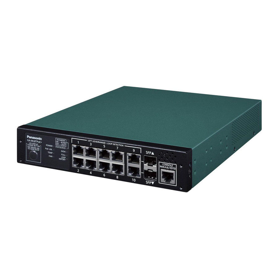
- Page 1 GA-ML Series WEB Reference Model Number PN260493N/PN260493H/PN260893/ PN260893H/PN260894/PN261693/ PN262492/PN262493 • Thank you for purchasing our product. • This manual provides important information about safe and proper operations of this Switching Hub.
- Page 2 The target model for this WEB reference is as follows Model name Model number Firmware version GA-ML4TPoE+ PN260493N 3.0.0.00 and above GA-MLi4TPoE+ PN260493H 3.0.0.00 and above GA-ML8TPoE+ PN260893 3.0.0.00 and above GA-MLi8TPoE+ PN260893H 3.0.0.00 and above GA-ML8THPoE+ PN260894 3.0.0.00 and above GA-ML16TPoE+ PN261693 3.0.0.00 and above GA-ML24TCPoE+ PN262492 3.0.0.00 and above GA-ML24TPoE+ PN262493 3.0.0.00 and above...
-
Page 3: Table Of Contents
Table of Contents 1 Introduction ..................9 1.1 Related Documentation ..................9 2 Web User Interface (Web UI) ............10 2.1 Connecting to the Web UI ................. 10 2.2 Understanding the Web UI ................12 3 System ....................13 3.1 Device Information .................... 13 3.2 System Information Settings ................ - Page 4 4.5 RMON (Remote Monitoring) ................61 4.5.1 RMON Global Settings ................61 4.5.2 RMON Statistics Settings ................62 4.5.3 RMON History Settings ................64 4.5.4 RMON Alarm Settings ................66 4.5.5 RMON Event Settings ................67 4.6 Telnet/Web ....................... 69 4.7 Session Time-out ....................
- Page 5 5.4 Loop Detection Configuration ................. 126 5.4.1 Detecting and Blocking the Loop Settings ..........126 5.4.2 Loop History Log ..................128 5.5 Link Aggregation .................... 129 5.6 L2 Protocol Tunnel ..................131 5.7 L2 Multicast Control ..................134 5.7.1 IGMP Snooping ..................134 5.7.1.1 IGMP Snooping Settings ...............
- Page 6 7.1.6 Queue Rate Limiting ................205 7.2 Advanced Settings ..................207 7.2.1 DSCP Mutation Map ................207 7.2.2 Port Trust State and Mutation Binding ........... 208 7.2.3 DSCP CoS Mapping ................209 7.2.4 CoS Color Mapping ................210 7.2.5 DSCP Color Mapping ................211 7.2.6 Class Map ....................
- Page 7 9.3.8 Accounting Settings ................311 9.4 Authentication ....................314 9.4.1 Authentication Dynamic VLAN Settings ..........314 9.4.2 Authentication Status Table ..............315 9.4.3 2-Step Authentication Settings ............... 316 9.5 RADIUS (Remote Authentication Dial-In User Service) ........317 9.5.1 RADIUS Global Settings ................. 317 9.5.2 RADIUS Server Settings ................
- Page 8 10.2 DDM (Digital Diagnostic Monitoring) ............. 369 10.2.1 DDM Settings ..................369 10.2.2 DDM Temperature Threshold Settings ..........371 10.2.3 DDM Voltage Threshold Settings ............372 10.2.4 DDM Bias Current Threshold Settings ........... 373 10.2.5 DDM TX Power Threshold Settings ............374 10.2.6 DDM RX Power Threshold Settings ............
- Page 9 14.2.2.1 Configuration Restore from HTTP ..........414 14.2.2.2 Configuration Restore from TFTP ..........415 14.2.2.3 Configuration Recovery from FTP Servers ........416 14.2.2.4 Configuration Restore from RCP ..........417 14.2.2.5 Configuration Backup to HTTP ............ 418 14.2.2.6 Configuration Backup to TFTP ............. 419 14.2.2.7 Configuration Backup to FTP Servers ...........
- Page 10 16 Appendix - System Trap Entries .............475 16.1 BPDU Guard ....................475 16.2 DDM ......................476 16.3 DHCP Server Protect ..................477 16.4 Gratuitous ARP ..................... 478 16.5 LLDP-MED ..................... 479 16.6 Detecting Loops .................... 480 16.7 MAC Based Access Control ................481 16.8 MAC Notification ..................
-
Page 11: Introduction
Web UI, and will be referred to as the “switch” in this document. Refer to the instruction found on our website (Panasonic Life Solutions Networks) or the manual of our products regarding the name of each part of them, the installation-method, and the separately sold option. -
Page 12: Web User Interface (Web Ui)
2 Web User Interface (Web UI) 2.1 Connecting to the Web UI Web User Interface (Web UI) Connecting to the Web UI You can directly or indirectly access the Web UI of a switch from any networking nodes, which are connected to an Ethernet port, by using the standard web browser. - Page 13 2 Web User Interface (Web UI) 2.1 Connecting to the Web UI Figure 2-3 Main Window of Web UI...
-
Page 14: Understanding The Web Ui
2 Web User Interface (Web UI) 2.2 Understanding the Web UI Understanding the Web UI The Web UI is divided into two sections (frame A and B) as illustrated in the figure below. Figure 2-4 All the features available in the Web UI of the switch are categorized into folders in frame A above. -
Page 15: System
3 System 3.1 Device Information System Device Information Use the following window to display general switch information and utilization (or usage). As you log-into the Web UI of the switch, the window is displayed from the beginning. Click the GA-MLxxT link (in Frame A) to display the following window. Figure 3-1 Device Information... -
Page 16: System Information Settings
3 System 3.2 System Information Settings System Information Settings Use the following window to implement the system information settings and display its settings. Choose System > System Information Settings to display the following window. Figure 3-2 System Information Settings In the section of System Information Settings, you can configure the following parameters. -
Page 17: Port Settings
3 System 3.3 Port Settings 3.3.1 Port Settings Port Settings 3.3.1 Port Settings Use the following window, and then implement the port settings on the switch to display its settings. Choose System > Port Configuration > Port Settings to display the following window. - Page 18 3 System 3.3 Port Settings 3.3.1 Port Settings Parameter Overview MDIX Choose an object of MDIX (Medium Dependent Interface Crossover). The options available are as follows. • Auto - This value automatically senses an optimum type of cables. • Normal - Choose this for normal cables. Selecting it makes a port to become the MDIX mode, and that allows a straight-through cable to connect to a PC LAN adapter.
- Page 19 3 System 3.3 Port Settings 3.3.1 Port Settings Parameter Overview Speed The following options are available to choose. • Automatic - In the case of a copper-port, an auto negotiation starts, and then it allows the speed and flow control to negotiate with its link-partner. In the case of fiber-ports, the auto negotiation starts, and then it allows the clock and full-control to negotiate with its link-partner.
-
Page 20: Port Status
3 System 3.3.2 Port Status 3.3.2 Port Status Use the following window to display the physical port-status and settings of the switch. Choose System > Port Configuration > Port Status to display the following window. Figure 3-4 Port Status... -
Page 21: Port Gbic
3 System 3.3.3 Port GBIC 3.3.3 Port GBIC Use the following window to display the information about the transceiver plugged into a physical port of the switch. GBIC stands for Gigabit Interface Converter. Choose System > Port Settings > Port GBIC to display the following window. -
Page 22: Port Auto Negotiation
3 System 3.3.4 Port Auto Negotiation 3.3.4 Port Auto Negotiation Use the following window to display an Auto Negotiation table of a port and its information. Choose System > Port Configuration > Port Auto Negotiation to display the following window. Figure 3-6 Port Auto Negotiation... -
Page 23: Error Disable Settings
3 System 3.3.5 Error Disable Settings 3.3.5 Error Disable Settings Use the following window, and then implement the settings on the error disable feature to display its settings. Choose System > Port Configuration > Error Disable Settings to display the following window. Figure 3-7 Error Disable Settings In the section of the configuration of Error Disable Recovery, you can configure the following parameters. -
Page 24: Jumbo Frame
3 System 3.3.6 Jumbo Frame 3.3.6 Jumbo Frame Use the following window, and then configure the jumbo frame to display its settings. The jumbo frame is the Ethernet frame, which consists of the payload, and its size is more than 1,518 (bytes). Choose System >... -
Page 25: Port Grouping Configuration
3 System 3.3.7 Port Grouping Configuration 3.3.7 Port Grouping Configuration Use the following window to configure the port-grouping and display its settings. Choose System > Port Configuration > Port Grouping Configuration to display the following window. Figure 3-9 Port Grouping Configuration In the section of Port Grouping Configuration, you can configure the following parameters. -
Page 26: System Log
3 System 3.4 System Log 3.4.1 System Log Settings System Log 3.4.1 System Log Settings Use the following window to implement the settings on system logs and display its settings. Choose System > System Log > System Log Settings to display the following window. - Page 27 3 System 3.4 System Log 3.4.1 System Log Settings Parameter Overview Identification Name Enter the identification name you use. The number of characters can be used up to 15. Specify the name of a discriminator profile. Based on the filtering standard stipulated on this profile, buffer-log messages will be filtered.
- Page 28 3 System 3.4 System Log 3.4.1 System Log Settings Parameter Overview Identification Name Enter an identification name to use it. The number of characters can be used up to 15. Specify the name of a discriminator profile. Based on the filtering standard stipulated on this profile, SMTP log messages will be filtered.
-
Page 29: System Log Discriminator Settings
3 System 3.4.2 System Log Discriminator Settings 3.4.2 System Log Discriminator Settings Use the following window to implement the settings on a discriminator and display its settings. Choose System > System Log > System Log Discriminator Settings to display the following window. Figure 3-11 System Log Discriminator Settings In the section of the Discriminator Log Settings, you can configure the following parameters. -
Page 30: System Log Server Settings
3 System 3.4.3 System Log Server Settings 3.4.3 System Log Server Settings Use the following window to implement the settings on the server, which is used on the system-log, and to display its settings. Choose System > System Log > System Log Server Settings to display the following window. - Page 31 3 System 3.4.3 System Log Server Settings Parameter Overview Facility Choose the facility number that are logged. The range is from 0 to 23. Each facility-number is associated with the specific facility below. See the following table. Facility- Facility Facility Description Number Name user...
-
Page 32: System Log
3 System 3.4.4 System Log 3.4.4 System Log Use the following window to display and clear system logs. Choose System > System Log > System Log Settings to display the following window. Figure 3-13 System Log Click the Clear Log button to clear the log-entry from the table above. If two or more pages exist, enter their page number. -
Page 33: System Attack Log
3 System 3.4.5 System Attack Log 3.4.5 System Attack Log Use the following window to display and clear the system attack log. Choose System > System Log > System Attack Log to display the following window. Figure 3-14 System Attack Log Click the Clear Attack Log button to clear the entry of attack logs from a table. -
Page 34: System Authentication Log
3 System 3.4.6 System Authentication Log 3.4.6 System Authentication Log Use the following window to implement the settings on a system authentication log and display its settings. Choose System > System Log > System Authentication Log to display the following window. Figure 3-15 System Authentication Log In the section of System Authentication Log, you can configure the following parameters. -
Page 35: Time And Sntp (Simple Network Time Protocol)
3 System 3.5 Time and SNTP (Simple Network Time Protocol) 3.5.1 Clock Settings Time and SNTP (Simple Network Time Protocol) 3.5.1 Clock Settings Use the following window to implement the settings on time and date, which is used on the time-dependent features of the switch, and to display its settings. -
Page 36: Time Zone Settings
3 System 3.5.2 Time Zone Settings 3.5.2 Time Zone Settings Use the following window to implement the settings on DST (Summer- time) and time zone to display its settings. Choose System > Time and SNTP > Time Zone Settings to display the following window. - Page 37 3 System 3.5.2 Time Zone Settings In the section of Recurring Settings, you can configure the following parameters. Parameter Overview From: Week of the Select the week when summer-time starts. Month From: Day of the Select the day when summer-time starts. Week From: Month Select the month when summer-time starts.
-
Page 38: Sntp Settings
3 System 3.5.3 SNTP Settings 3.5.3 SNTP Settings Use the following window to implement the settings on SNTP (Simple Network Time Protocol) and display its settings. Use the SNTP, and then obtain a synchronization automatically and periodically between the configuration of time and date for a switch and the settings hosted by an SNTP server. -
Page 39: Time Range
3 System 3.6 Time Range Time Range Use the following window to implement the settings on a time range profile and display its settings. Choose System > Time Range to display the following window. Figure 3-19 Time Range In the section of Time Range, you can configure the following parameters. - Page 40 3 System 3.6 Time Range If two or more pages exist, enter the page number. Then click Go to move to the specific page.
-
Page 41: Poe Configuration
3 System 3.7 PoE Configuration 3.7.1 PoE Global Configuration PoE Configuration 3.7.1 PoE Global Configuration implement the common configuration Use the following window to on a device regarding PoE and to display its settings. Choose System > PoE Configuration > PoE Global Configuration to display the following window. - Page 42 3 System 3.7 PoE Configuration 3.7.1 PoE Global Configuration Click Apply to reflect the change.
-
Page 43: Poe Port Configuration
3 System 3.7.2 PoE Port Configuration 3.7.2 PoE Port Configuration Use the following window to implement the settings on the power-supply per port. Choose System > PoE Configuration > PoE Port Configuration to display the following window. Figure 3-21 PoE Port Configuration In the section of PoE Port Configuration, you can configure the following parameters. -
Page 44: Poe Schedule Configuration
3 System 3.7.3 PoE Schedule Configuration 3.7.3 PoE Schedule Configuration Use the following window to implement the settings on the PoE scheduler and display the schedule information. Choose System > PoE Configuration > PoE Global Settings to display the following window. Figure 3-22 PoE Schedule Configuration In the section of the PoE Schedule Configuration, you can configure the following parameters. - Page 45 3 System 3.7.3 PoE Schedule Configuration Parameter Overview Date List Index This parameter displays the number regarding the date list where the PoE schedule is conducted. PoE Action This parameter displays an action of the PoE schedule. The options available are OFF, ON and OFF/ON. Order By This parameter configures the sequence of displaying the PoE schedule.
-
Page 46: Poe Schedule Port List Configuration
3 System 3.7.4 PoE Schedule Port List Configuration 3.7.4 PoE Schedule Port List Configuration Use the following window, and then implement the settings on the port- list of a PoE scheduler to display the port-list information. Choose System > PoE Configuration > PoE Schedule Port List Configuration to display the following window. -
Page 47: Poe Date List Configuration
3 System 3.7.5 PoE Date List Configuration 3.7.5 PoE Date List Configuration Use the following window, and then implement the settings on the date list of the PoE scheduler to display its settings. Choose System > PoE Configuration > PoE Date List Configuration to display the following window. -
Page 48: Poe Auto-Reboot Settings
3 System 3.7.6 PoE Auto-Reboot Settings 3.7.6 PoE Auto-Reboot Settings Use the following window to configure the PoE auto-reboot Choose System > PoE Configuration > PoE Auto Reboot to display the following window. Figure 3-25 PoE Auto-Reboot Settings Parameter Overview Ping Interval This parameter configures the interval with seconds (as (1-86400) - Page 49 3 System 3.7.6 PoE Auto-Reboot Settings Parameter Overview Number of LLDP Error This parameter configures the number of retrials during Retries errors as for monitoring the auto-reboot LLDP, which is (1-10) used for the PoE auto-reboot (factory default settings: Average Traffics This parameter configures the interval for calculating (1-60) the average value of traffics, which exist in a device...
- Page 50 3 System 3.7.6 PoE Auto-Reboot Settings Parameter Overview PoE OFF/ON Interval This parameter configures the interval of PoE power- supply OFF/ON when your switch determines an abnormality of the PoE auto-reboot. PoE OFF/ON Repeat This parameter enables or disables the repeat-execution of PoE power-supply OFF/ON when your switch determines an abnormality of PoE auto-reboot.
-
Page 51: Management
4 Management 4.1 User Accounts Encryption Management User Accounts Encryption Use the following window to enable or disable the user accounts encryption. Choose Management > User Accounts Encryption to view the following window. Figure 4-1 User Accounts Encryption In the section of User Accounts Encryption, you can configure the following parameter. -
Page 52: Login Method
4 Management 4.2 Login Method Login Method Use the following window to implement the settings on and display the log-in method for each log-in application, which is supported on the switch. Choose Management > Login Method to display the following window. Figure 4-2 Login Method In the section of Enable Password, you can configure the following parameters. - Page 53 4 Management 4.2 Login Method In the section of Login Method, you can configure the following parameter. Parameter Overview Log-in Method Click Edit, and then this parameter becomes configurable. Choose the log-in method for the application specified. The options available are as follows.
-
Page 54: Ip Setup
4 Management 4.3 IP Setup 4.3.1 IP Setup Protocol Settings IP Setup 4.3.1 IP Setup Protocol Settings Use the following window to enable or disable a function of an IP setup interface. Choose Management > IP Setup > IP Setup Protocol Settings to display the following window. -
Page 55: Snmp
4 Management 4.4 SNMP 4.4.1 SNMP Group Table Settings SNMP 4.4.1 SNMP Group Table Settings Use the following window to implement the settings on the SNMP group table settings and display its settings. The SNMP group maps SNMP users to SNMP view. Choose Management >... - Page 56 4 Management 4.4 SNMP 4.4.1 SNMP Group Table Settings Parameter Overview Security Level Choose the security level after choosing SNMPv3 to use from User-base Security Model. The options available are as follows. • NoAuthNoPriv - An authentication is not implemented, and encrypting packets, which are transmitted between a switch and a remote SNMP manager, is not performed.
-
Page 57: Snmp Engine Id Local Settings
4 Management 4.4.2 SNMP Engine ID Local Settings 4.4.2 SNMP Engine ID Local Settings Use the following window to implement the settings and display a local SNMP engine ID. The engine ID is unique to a switch and is used for implementing SNMPv3 (SNMP version 3). -
Page 58: Snmp User Table Settings
4 Management 4.4.3 SNMP User Table Settings 4.4.3 SNMP User Table Settings Use this window to implement the SNMP user settings and display its settings. Choose Management > SNMP > SNMP User Table Settings to display the following window. Figure 4-6 SNMP User Table Settings In the section of SNMP User Settings, you can configure the following parameters. - Page 59 4 Management 4.4.3 SNMP User Table Settings Parameter Overview Password Enter the password for an authentication protocol. • The number of characters for the MD5-password must be between 8 and 16. • The number of characters for the SHA-password must be between 8 and 20. Priv-Protocol by After choosing v3 from SNMP Version and Password Password...
- Page 60 4 Management 4.4.3 SNMP User Table Settings Click Add to add new entries based on the information specified. Click Delete to delete the entries.
-
Page 61: Snmp Host Table Settings
4 Management 4.4.4 SNMP Host Table Settings 4.4.4 SNMP Host Table Settings Use the following window to implement the settings on an SNMP host and display its settings. Choose Management > SNMP > SNMP Host Table Settings to display the following window. Figure 4-7 SNMP Host-table Settings In the section of SNMP Host Settings, you can configure the following parameters. - Page 62 4 Management 4.4.4 SNMP Host Table Settings Parameter Overview UDP Port Enter the UDP port-number. The default port-number is 162, and the range is from 1 to 65,535. Some port- numbers may conflict with other protocols. Community Character Enter the community character strings to be transmitted String / with the notification packets.
-
Page 63: Rmon (Remote Monitoring)
4 Management 4.5 RMON (Remote Monitoring) 4.5.1 RMON Global Settings RMON (Remote Monitoring) 4.5.1 RMON Global Settings Use the following window to enable or disable the trap state on RMON rising alarm and RMON falling alarm. Choose Management > RMON > RMON Global Settings to display the following window. -
Page 64: Rmon Statistics Settings
4 Management 4.5.2 RMON Statistics Settings 4.5.2 RMON Statistics Settings Use the following window to implement the settings on the RMON statistics for the port specified and display its settings. Choose Management > RMON > RMON Statistics Settings to display the following window. - Page 65 4 Management 4.5.2 RMON Statistics Settings Figure 4-10 RMON Statistics Settings (Show Detail.) Click Back to return to the previous window.
-
Page 66: Rmon History Settings
4 Management 4.5.3 RMON History Settings 4.5.3 RMON History Settings Use the following window to implement the RMON history settings on the port specified and display its settings. Choose Management > RMON > RMON History Settings to display the following window. Figure 4-11 RMON History Settings In the section of RMON History Settings, you can configure the following parameters. - Page 67 4 Management 4.5.3 RMON History Settings Click Show Detail to display the following window. Figure 4-12 RMON History Table (Show Detail.) Click Back to return to the previous window.
-
Page 68: Rmon Alarm Settings
4 Management 4.5.4 RMON Alarm Settings 4.5.4 RMON Alarm Settings Choose Management > RMON > RMON Alarm Settings to display the following window. Figure 4-13 RMON Alarm Settings In the section of RMON Alarm Settings, you can configure the following parameters. -
Page 69: Rmon Event Settings
4 Management 4.5.5 RMON Event Settings 4.5.5 RMON Event Settings Use the following window to implement the RMON event settings and display its settings. Choose Management > RMON > RMON Event Settings to display the following window. Figure 4-14 RMON Event Settings In the section of RMON Event Settings, you can configure the following parameters. - Page 70 4 Management 4.5.5 RMON Event Settings Click View-log to display the following window. Figure 4-15 RMON Event Settings (View Log) Click Back to return to the previous window.
-
Page 71: Telnet/Web
4 Management 4.6 Telnet/Web Telnet/Web Use the following window to implement the settings on Telnet and Web of the switch and display its settings. Choose Management > Telnet/Web to display the following window. Figure 4-16 Telnet/Web In the section of the Telnet Settings, you can configure the following parameters. -
Page 72: Session Time-Out
4 Management 4.7 Session Time-out Session Time-out Use the following window to implement the settings on Web, Console, Telnet and the session time-out of the SSH connection and to display its settings. Choose Management > Session Time-out to display the following window. -
Page 73: Dhcp Auto Configuration
4 Management 4.8 DHCP Auto Configuration DHCP Auto Configuration Use the following window to enable or disable a function of the DHCP auto configuration. Choose Management > DHCP Auto Configuration to display the following window. Figure 4-18 DHCP Auto Configuration In the section of DHCP Auto Configuration, you can configure the following parameter. -
Page 74: Dns (Domain Name System)
4 Management 4.9 DNS (Domain Name System) 4.9.1 DNS Global Settings DNS (Domain Name System) 4.9.1 DNS Global Settings Use the following window to implement the global DNS settings and display its settings. Choose Management> DNS> DNS Global Settings to display the following window. -
Page 75: Dns Name Server Settings
4 Management 4.9.2 DNS Name Server Settings 4.9.2 DNS Name Server Settings Use the following window to implement the settings on a DNS name server and display its settings. Choose Management > DNS > DNS Name Server Settings to display the following window. -
Page 76: Dns Host Settings
4 Management 4.9.3 DNS Host Settings 4.9.3 DNS Host Settings Use the following window to implement the DNS host settings and display its settings. Choose Management > DNS > DNS Host Settings to display the following window. Figure 4-21 DNS Host Settings In the section of Static Host Settings, you can configure the following parameters. -
Page 77: File System
4 Management 4.10 File System 4.10 File System Use the following window to implement the settings on a file system of a switch and display its settings. Choose Management > File System to display the following window. Figure 4-22 File System You can configure the following parameter. - Page 78 4 Management 4.10 File System Click Rename to rename a specific file-name. Click Delete to delete a file or folder from the file system. Click Copy to display the following window. Figure 4-24 File System (Copy) You can configure the following parameters. Parameter Overview Source...
-
Page 79: Smtp Settings
4 Management 4.11 SMTP Settings 4.11 SMTP Settings Use the following window to implement the SMTP (Simple Mail Transfer Protocol) settings and display its settings. Choose Management > SMTP Settings to display the following window. Figure 4-25 SMTP Settings In the section of the SMTP Global Settings, you can configure the following parameters. - Page 80 4 Management 4.11 SMTP Settings Click Apply to reflect the change. In the section of SMTP Email Receiver Address, you can configure the following parameter. Parameter Overview Adding an Email Enter the email address of a receiver. The number of Receiver characters for this character strings can be up to 254.
-
Page 81: Nlb Fdb Settings
4 Management 4.12 NLB FDB Settings 4.12 NLB FDB Settings Use the following window to implement the settings on NLB (Network Load Balancing) and FDB (File Database) of the port specified and to display its settings. Choose Management > NLB FDB Settings to display the following window. -
Page 82: L2 Features
5 L2 Features 5.1 FDB (Forwarding Database) 5.1.1 Static FDB 5.1.1.1 Unicast Static FDB L2 Features FDB (Forwarding Database) 5.1.1 Static FDB 5.1.1.1 Unicast Static FDB Use the following window to implement the settings on a static-unicast forwarding and display its settings. Choose L2 Features >... - Page 83 5 L2 Features 5.1 FDB (Forwarding Database) 5.1.1 Static FDB 5.1.1.1 Unicast Static FDB If two or more pages exist, enter the page-numbers. Then click Go to move to a specific page.
-
Page 84: Multicast Static Fdb
5 L2 Features 5.1.1.2 Multicast Static FDB 5.1.1.2 Multicast Static FDB Use the following window to implement the settings on Multicast static FDB and display its settings. Choose L2 Features > FDB > Static FDB > Multicast Static FDB to display the following window. -
Page 85: Mac Address Table Settings
5 L2 Features 5.1.2 MAC Address Table Settings 5.1.2 MAC Address Table Settings Use the following window to implement the settings on a MAC address table and display its settings. Choose L2 Features > FDB > MAC Address Table Settings to display the following window. - Page 86 5 L2 Features 5.1.2 MAC Address Table Settings In the section of MAC Address Port Learning Settings, you can configure the following parameters. Parameter Overview From Port/ To Port Choose the port you use. State This parameter enables or disables a function of a learning MAC address of the port specified.
- Page 87 5 L2 Features 5.1.2 MAC Address Table Settings In the section of a MAC Address for Searching VLAN Learning, you can configure the following parameter. Parameter Overview Enter the VLAN ID you use. The range is from 1 to 4,094. Click Find to search and display the entries in a table based on the search condition specified.
-
Page 88: Mac Address Table
5 L2 Features 5.1.3 MAC Address Table 5.1.3 MAC Address Table Use the following window to display and clear the entry of a MAC address table. Choose L2 Features > FDB > MAC Address Table to display the following window. Figure 5-6 MAC Address Table In the section of the MAC Address Table, you can configure the following parameters. -
Page 89: Mac Notification
5 L2 Features 5.1.4 MAC Notification 5.1.4 MAC Notification Use the following window to implement the settings on a global MAC notification and MAC notification of the port specified and display its settings. Choose L2 Features > FDB > MAC Notification to display the following window. - Page 90 5 L2 Features 5.1.4 MAC Notification Figure 5-8 MAC Notification (MAC Notification History)
-
Page 91: Vlan (Virtual Local Area Network)
5 L2 Features 5.2 VLAN (Virtual Local Area Network) 5.2.1 802.1Q VLAN VLAN (Virtual Local Area Network) 5.2.1 802.1Q VLAN Use the following window to implement the settings on IEEE 802.1Q VLAN and display its settings. Choose L2 Features > VLAN > 802.1Q VLAN to display the following window. - Page 92 5 L2 Features 5.2 VLAN (Virtual Local Area Network) 5.2.1 802.1Q VLAN Click See All to search and display all the entries available. Click Edit to edit the entry-settings. Click Delete to delete the entry. If two or more pages exist, enter the page numbers. Then click Go to move to a specific page.
-
Page 93: Protocol Vlan
5 L2 Features 5.2.2 802.1v Protocol VLAN 5.2.2.1 Protocol VLAN Profile 5.2.2 802.1v Protocol VLAN 5.2.2.1 Protocol VLAN Profile Use the following window to implement the settings on IEEE 802.1v protocol VLAN and display its settings. Two or more VLANs are supported on each protocol. - Page 94 5 L2 Features 5.2.2 802.1v Protocol VLAN 5.2.2.1 Protocol VLAN Profile Parameter Overview Ether-type Enter the Ethernet-type value of a group. Use the protocol value to identify a protocol of the frame-type specified. The range is from 0x0 to 0xFFFF. The octet character strings includes one of the following values, depending on a frame-type.
-
Page 95: Protocol Vlan Profile Interface
5 L2 Features 5.2.2.2 Protocol VLAN Profile Interface 5.2.2.2 Protocol VLAN Profile Interface Use the following window to implement the settings on an interface of a protocol VLAN profile and display its settings. Choose L2 Features > VLAN > 802.1v Protocol VLAN > Protocol VLAN Profile Interface to display the following window. -
Page 96: Gvrp
5 L2 Features 5.2.3 GVRP 5.2.3.1 GVRP Global 5.2.3 GVRP 5.2.3.1 GVRP Global Use the following window to implement the global settings on GVRP (GARP VLAN Registration Protocol) and display its settings. GARP stands for Generic Attribute Registration Protocol. Choose L2 Features > VLAN > GVRP > GVRP Global to display the following window. -
Page 97: Gvrp Port
5 L2 Features 5.2.3.2 GVRP Port 5.2.3.2 GVRP Port Use the following window to implement the settings on GVRP Port and display its settings. Choose L2 Features > VLAN > GVRP > GVRP Port to display the following window. Figure 5-13 GVRP Port In the section of GVRP Port, you can configure the following parameters. -
Page 98: Gvrp Advertise Vlan
5 L2 Features 5.2.3.3 GVRP Advertise VLAN 5.2.3.3 GVRP Advertise VLAN Use the following window to implement the settings on GVRP advertise VLAN and display its settings. Choose L2 Features > VLAN > GVRP > GVRP Advertise VLAN to display the following window. -
Page 99: Gvrp Forbidden Vlan
5 L2 Features 5.2.3.4 GVRP Forbidden VLAN 5.2.3.4 GVRP Forbidden VLAN Use the following window to implement the settings on GVRP forbidden VLAN and display its settings. Choose L2 Features > VLAN > GVRP > GVRP Forbidden VLAN to display the following window. Figure 5-15 GVRP Forbidden VLAN In the section of GVRP Forbidden VLAN, you can configure the following parameters. -
Page 100: Gvrp Statistics Table
5 L2 Features 5.2.3.5 GVRP Statistics Table 5.2.3.5 GVRP Statistics Table Use the following window to display and clear the GVRP statistics. Choose L2 Features > VLAN > GVRP > GVRP Statistics Table to display the following window. Figure 5-16 GVRP Statistics Table In the section of GVRP Statistics Table, you can configure the following parameter. -
Page 101: Asymmetric Vlan
5 L2 Features 5.2.4 Asymmetric VLAN 5.2.4 Asymmetric VLAN Use the following window to implement the settings on an asymmetric VLAN and display its settings. Choose L2 Features > VLAN > Asymmetric VLAN to display the following window. Figure 5-17 Asymmetric VLAN In the section of the Asymmetric VLAN, you can configure the following parameter. -
Page 102: Mac Vlan
5 L2 Features 5.2.5 MAC VLAN 5.2.5 MAC VLAN Use the following window to implement the settings on a MAC based VLAN. Then, a static MAC based VLAN entry is configured. If this is associated with a port, the VLAN operating on the port becomes changed. Choose L2 Features >... -
Page 103: Vlan Interface
5 L2 Features 5.2.6 VLAN Interface 5.2.6 VLAN Interface Use the following window to implement the settings on the VLAN interface and display its settings. Choose L2 Features > VLAN > VLAN Interface to display the following window. Figure 5-19 VLAN Interface Click Show Detail to display details on the entry. - Page 104 5 L2 Features 5.2.6 VLAN Interface In the section of VLAN Interface Settings, you can configure the following parameters. Parameter Overview VLAN Mode Choose the option of VLAN mode. The options available are Access, Hybrid, Trunk, Promiscuous and Host. Acceptable Frames Choose an operating option for acceptable frames.
- Page 105 5 L2 Features 5.2.6 VLAN Interface In the section of VLAN Interface Settings, you can configure the following parameters. Parameter Overview VLAN Mode Choose the option of VLAN mode. The options available are Access, Hybrid, Trunk, Promiscuous and Host. Acceptable Frames Choose an operating option for acceptable frames.The options available are Tagged only, Untagged only and Admit All.
- Page 106 5 L2 Features 5.2.6 VLAN Interface In the section of VLAN Interface Settings, you can configure the following parameters. Parameter Overview VLAN Mode Choose the option of VLAN mode. The options available are Access, Hybrid, Trunk, Promiscuous and Host. Acceptable Frames Choose an operating option for acceptable frames. ...
- Page 107 5 L2 Features 5.2.6 VLAN Interface Parameter Overview Acceptable Frames Choose an operating option for acceptable frames. The options available are Tagged only, Untagged only and Admit All. Checking Ingress This parameter enables or disables a function of checking ingresss. Clone If you choose this option, you need to enable the clone function.
-
Page 108: Subnet Vlan
5 L2 Features 5.2.7 Subnet VLAN 5.2.7 Subnet VLAN Use the following window to implement the settings on a subnet VLAN and display its settings. Configure the subnet VLAN. If you receive untagged IP packets or priority tag IP packets through a port, both of them are cross-checked (along) with the subnet VLAN entry by using the source IP address. -
Page 109: Voice Vlan
5 L2 Features 5.2.8 Voice VLAN 5.2.8.1 Voice VLAN Global 5.2.8 Voice VLAN 5.2.8.1 Voice VLAN Global Use the following window to implement the settings on a global voice VLAN. Enable or disable to set a voice VLAN function to global, and then specify the voice VLAN of a switch. - Page 110 5 L2 Features 5.2.8 Voice VLAN 5.2.8.1 Voice VLAN Global Click Apply to reflect the change.
-
Page 111: Voice Vlan Port
5 L2 Features 5.2.8.2 Voice VLAN Port 5.2.8.2 Voice VLAN Port Use the following window to implement the settings on a voice VLAN interface and display its settings. Choose L2 Features > VLAN > Voice VLAN > Voice VLAN Port to display the following window. - Page 112 5 L2 Features 5.2.8.2 Voice VLAN Port Parameter Overview Mode Chooses a mode. The options available are as follows. • Auto Untagged - the untagged membership of the voice VLAN is automatically learned. • Auto-Tag - the tagged membership regarding the voice VLAN is learned automatically.
-
Page 113: Voice Vlan Oui
5 L2 Features 5.2.8.3 Voice VLAN OUI 5.2.8.3 Voice VLAN OUI Use the following window to implement the settings on voice VLAN OUI and display its settings. You can associate the OUI of a user definition with the voice VLAN. If a source MAC address of packets received corresponds with an optional OUI pattern, the packets received are evaluated as voice packets. -
Page 114: Voice Lan Device
5 L2 Features 5.2.8.4 Voice LAN Device 5.2.8.4 Voice LAN Device Use the following window to display a table of the voice VLAN device and its information. Choose L2 Features > VLAN > Voice VLAN > Voice VLAN Device to display the following window. -
Page 115: Voice Vlan Lldp-Med Device
5 L2 Features 5.2.8.5 Voice VLAN LLDP-MED Device 5.2.8.5 Voice VLAN LLDP-MED Device Use the following window to display a table of the voice VLAN LLDP-MED device and its information. Choose L2 Features > VLAN > Voice VLAN > Voice VLAN LLDP-MED Device to display the following window. -
Page 116: Private Vlan
5 L2 Features 5.2.9 Private VLAN 5.2.9 Private VLAN Use the following window to implement the settings on a private VLAN and display its settings. Choose L2 Features > VLAN > Private VLAN to display the following window. Figure 5-32 Private VLAN In the section of the Private VLAN, you can configure the following parameters. - Page 117 5 L2 Features 5.2.9 Private VLAN In the section of Private VLAN Association, you can configure the following parameters. Parameter Overview VID List Enter the private VLAN ID you use. You can enter its consecutive VLAN IDs, by delimiting with a comma, or enter the range of VLAN IDs by delimiting with a hyphen.
- Page 118 5 L2 Features 5.2.9 Private VLAN In the section of the Private VLAN Mapping, you can configure the following parameters. Parameter Overview From Port/ To Port Choose the port you use. Primary VID Enter the primary VLAN ID you use. The range is from 1 to 4,094.
-
Page 119: Stp (Spanning Tree Protocol)
5 L2 Features 5.3 STP (Spanning Tree Protocol) 5.3.1 STP Global Settings STP (Spanning Tree Protocol) 5.3.1 STP Global Settings Use the following window to implement the settings on global STP and display its settings. Choose L2 Features > STP > STP Global Settings to display the following window. - Page 120 5 L2 Features 5.3 STP (Spanning Tree Protocol) 5.3.1 STP Global Settings Parameter Overview Priority Choose the value of an STP priority. You can specify the value within the range from 0 to 61,440. By default, the value is 32,768. The lower the value, the higher priority will be.
- Page 121 5 L2 Features 5.3 STP (Spanning Tree Protocol) 5.3.1 STP Global Settings Parameter Overview Max Hops Enter the maximum number (value) of hops to allow. The range is from 6 to 40 (hops). By default, the value is equal to 20 (hops). Use the value to configure the number of hops between devices existing in a domain of a spanning tree before removing BPDU packets, which are transmitted by a switch.
-
Page 122: Stp Port Settings
5 L2 Features 5.3.2 STP Port Settings 5.3.2 STP Port Settings Use the following window to implement the settings on STP ports and display its settings. Choose L2 Features > STP > STP Port Settings to display the following window. Figure 5-34 STP Port Settings In the section of STP Port Settings, you can configure the following parameters. - Page 123 5 L2 Features 5.3.2 STP Port Settings Parameter Overview Link Type Choose the link type option. The options available are Auto, P2P and Share. A full-duplex port is considered to have a Point-to-Point (P2P) connection. On the other hand, a half-duplex port is considered to have a shared connection.
-
Page 124: Mst Configuration Identification
5 L2 Features 5.3.3 MST Configuration Identification 5.3.3 MST Configuration Identification Use the following window to implement the settings on an MST configuration ID and display its settings. This configuration allows you to identify the Multiple Spanning Tree Instance (MSTI), which is configured on a switch. - Page 125 5 L2 Features 5.3.3 MST Configuration Identification Parameter Overview Instance ID Enter an Instance ID. The range is from 1 to 64. Action Choose the action you perform. The options available are Adding VID and Deleting VID. VID List Enter the VLAN ID you use. You can enter its consecutive VLAN IDs by delimiting with a comma.
-
Page 126: Stp Instance
5 L2 Features 5.3.4 STP Instance 5.3.4 STP Instance Use the following window to implement the settings on an STP instance. and display its settings. Choose L2 Features > STP > STP Instance to display the following window. Figure 5-36 STP Instance In the section of the STP Instance, you can configure the following parameter. -
Page 127: Mstp Port Information
5 L2 Features 5.3.5 MSTP Port Information 5.3.5 MSTP Port Information Use the following window to implement the settings and display MSTP port information. Choose L2 Features > STP > MSTP Port Information to display the following window. Figure 5-37 MSTP Port Information In the section of MSTP Port Information, you can configure the following parameters. -
Page 128: Loop Detection Configuration
5 L2 Features 5.4 Loop Detection Configuration 5.4.1 Detecting and Blocking the Loop Settings Loop Detection Configuration 5.4.1 Detecting and Blocking the Loop Settings Use the following window to implement the settings on detecting and blocking loops and display its settings. Choose L2 Features >... - Page 129 5 L2 Features 5.4 Loop Detection Configuration 5.4.1 Detecting and Blocking the Loop Settings Parameter Overview Recovering Loops This parameter enables or disables a function of recovering loops. If the function is set to enabled, ports become recovered to a normal condition after the value of time-out expires.
-
Page 130: Loop History Log
5 L2 Features 5.4.2 Loop History Log 5.4.2 Loop History Log Use the following window to display and clear a loop history log. Choose L2 Features > Detecting and Blocking Loops > Loop History Log to display the following window. Figure 5-39 Loop History Log Click the Clear Log button to clear log entries from a table. -
Page 131: Link Aggregation
5 L2 Features 5.5 Link Aggregation Link Aggregation Use the following window to implement the settings on a link aggregation and display its settings. Choose L2 Features > Link Aggregation to display the following window. Figure 5-40 Link Aggregation In the first section, you can configure the following parameters. Parameter Overview System Priority... - Page 132 5 L2 Features 5.5 Link Aggregation Parameter Overview Group ID Enter the channel-group number. The range is from 1 to 32. If a physical port participates in a channel group for the first time, the port-channel is automatically created. One interface can participate in one channel group, only.
-
Page 133: L2 Protocol Tunnel
5 L2 Features 5.6 L2 Protocol Tunnel L2 Protocol Tunnel Use the following window to implement the settings on layer 2 protocol tunnel and display its settings. Choose L2 Features > L2 Protocol Tunnel to display the following window. Figure 5-42 L2 Protocol Tunnel (L2 Protocol Tunnel Global Settings) In the section of the L2 Protocol Tunnel Global Settings, you can configure the following parameters. - Page 134 5 L2 Features 5.6 L2 Protocol Tunnel Parameter Overview Tunneled Protocol Choose a tunneled protocol. The options available are as follows. • GVRP - GVRP packets are tunneled to the address, which is configured already. • STP - STP packets are tunneled to the address, which is configured already.
- Page 135 5 L2 Features 5.6 L2 Protocol Tunnel Parameter Overview Protocol MAC After choosing Protocol MAC as the Tunneled Protocol, the following options are available. Choose Protocol MAC from it. The options available are 01-00- 0C-CC-CC-CC and 01-00-0C-CC-CC-CD. Threshold If you choose Shutdown or Removal in the Type field, this parameter becomes available.
-
Page 136: L2 Multicast Control
5 L2 Features 5.7 L2 Multicast Control 5.7.1 IGMP Snooping 5.7.1.1 IGMP Snooping Settings 5.7 L2 Multicast Control 5.7.1 IGMP Snooping 5.7.1.1 IGMP Snooping Settings Use the following window to implement the settings on IGMP (Internet Group Management Protocol) Snooping and display its settings. Choose L2 Features >... - Page 137 5 L2 Features 5.7 L2 Multicast Control 5.7.1 IGMP Snooping 5.7.1.1 IGMP Snooping Settings Parameter Overview Enter the VLAN ID you use. The range is from 1 to 4,094. Click Find to search and display the entries in a table based on the search condition specified.
- Page 138 5 L2 Features 5.7 L2 Multicast Control 5.7.1 IGMP Snooping 5.7.1.1 IGMP Snooping Settings Figure 5-46 IGMP Snooping Settings (Edit and Revise) In the section of IGMP Snooping VLAN Settings, you can configure the following parameters. Parameter Overview Fast Leave This parameter enables or disables a function of an IGMP Snooping fast leave.
-
Page 139: Igmp Snooping Group Settings
5 L2 Features 5.7.1.2 IGMP Snooping Group Settings 5.7.1.2 IGMP Snooping Group Settings Use the following window to implement the settings on an IGMP Snooping group and display its settings. Choose L2 Features > L2 Multicast Control > IGMP Snooping > IGMP Snooping Group Settings to display the following window. - Page 140 5 L2 Features 5.7.1.2 IGMP Snooping Group Settings Click See All to search and display all the entries available. In the section of the IGMP Snooping Group Table, you can configure the following parameters. Parameter Overview Choose and enter VLAN IDs to use. The range is from 1 to 4,094.
-
Page 141: Igmp Snooping Filter Settings
5 L2 Features 5.7.1.3 IGMP Snooping Filter Settings 5.7.1.3 IGMP Snooping Filter Settings Use the following window to implement the settings on the IGMP Snooping filtering and display its settings. Choose L2 Features > L2 Multicast Control > IGMP Snooping > IGMP Snooping Filter Settings to display the following window. - Page 142 5 L2 Features 5.7.1.3 IGMP Snooping Filter Settings In the section of the settings on IGMP Snooping Limitation, you can configure the following parameters. Parameter Overview From Port to Port: Choose the port you use. from the Beggining to the End Number of Enter the number of limitations.
- Page 143 5 L2 Features 5.7.1.3 IGMP Snooping Filter Settings In the section of the settings on Access Group, you can configure the following parameters. Parameter Overview From Port to Port: Choose the port you use. from the Beggining to the End Action Click Add to add a new entry based on the information entered.
- Page 144 5 L2 Features 5.7.1.3 IGMP Snooping Filter Settings Figure 5-49 IGMP Snooping Filter Settings (Show Detail.) If two or more pages exist, enter the page numbers. Then click Go to move to a specific page. Click Back to return to the previous window.
-
Page 145: Igmp Snooping Multicast Router Information
5 L2 Features 5.7.1.4 IGMP Snooping Multicast Router Information 5.7.1.4 IGMP Snooping Multicast Router Information Use the following window to implement the settings on an IGMP Snooping Multicast router and display its settings. Choose L2 Features > L2 Multicast Control > IGMP Snooping > IGMP Snooping Multicast Router Information to display the following window. - Page 146 5 L2 Features 5.7.1.4 IGMP Snooping Multicast Router Information In the section of a port table of IGMP Snooping Multicast Router, you can configure the following parameter. Parameter Overview Enter the VLAN ID you use. The range is from 1 to 4,094.
-
Page 147: Igmp Snooping Statistics Settings
5 L2 Features 5.7.1.5 IGMP Snooping Statistics Settings 5.7.1.5 IGMP Snooping Statistics Settings Use the following window to display and clear the IGMP Snooping statistics. Choose L2 Features > L2 Multicast Control > IGMP Snooping > IGMP Snooping Statistics Settings to display the following window. Figure 5-51 IGMP Snooping Statistics Settings In the section of the IGMP Snooping Statistics Settings, you can configure the following parameters. - Page 148 5 L2 Features 5.7.1.5 IGMP Snooping Statistics Settings In the section of a table regarding the IGMP Snooping Statistics, you can configure the following parameters. Parameter Overview Search Type Choose the interface type. The options available are VLAN and Port. Enter the VLAN ID you use.
-
Page 149: Mld Snooping
5 L2 Features 5.7.2 MLD Snooping 5.7.2.1 MLD Snooping Settings 5.7.2 MLD Snooping 5.7.2.1 MLD Snooping Settings Use the following window to implement the settings on MLD Snooping (Multicast Listener Discovery Snooping) and display its settings. Choose L2 Features > L2 Multicast Control > MLD Snooping > MLD Snooping Settings to display the following window. - Page 150 5 L2 Features 5.7.2 MLD Snooping 5.7.2.1 MLD Snooping Settings Parameter Overview Enter the VLAN ID you use. The range is from 1 to 4,094. Click Find to search and display the entries in a table based on the search condition specified.
- Page 151 5 L2 Features 5.7.2 MLD Snooping 5.7.2.1 MLD Snooping Settings Figure 5-54 MLD Snooping Settings (Edit and Revise)
- Page 152 5 L2 Features 5.7.2 MLD Snooping 5.7.2.1 MLD Snooping Settings In the section of IGMP Snooping VLAN Settings, you can configure the following parameters. Parameter Overview Fast Leave This parameter enables or disables a function of MLD Snooping fast-leave. If enabled, the membership is immediately removed when the system receives the MLD leave messages.
-
Page 153: Mld Snooping Group Settings
5 L2 Features 5.7.2.2 MLD Snooping Group Settings 5.7.2.2 MLD Snooping Group Settings Use the following window to implement the settings on an MLD Snooping group and display its settings. Choose L2 Features > L2 Multicast Control > MLD Snooping > MLD Snooping Group Settings to display the following window. - Page 154 5 L2 Features 5.7.2.2 MLD Snooping Group Settings In the section of a table of MLD Snooping Static Group, you can configure the following parameters. Parameter Overview Choose and enter VLAN IDs to use. The range is from 1 to 4,094. Group Address Click the Radio button, and then enter an address of an IPv6 Multicast Group.
-
Page 155: Mld Snooping Filter Settings
5 L2 Features 5.7.2.3 MLD Snooping Filter Settings 5.7.2.3 MLD Snooping Filter Settings Use the following window to implement the settings on the MLD Snooping filtering and display its settings. Choose L2 Features > L2 Multicast Control > MLD Snooping > MLD Snooping Filtering Settings to display the following window. - Page 156 5 L2 Features 5.7.2.3 MLD Snooping Filter Settings In the section of the settings on MLD Snooping Limitation, you can configure the following parameters. Parameter Overview From Port/ To Port Choose the port you use. Number of Enter the number of limitations. Use this parameter to Limitations limit the number of MLD cash entries, which can be created.
- Page 157 5 L2 Features 5.7.2.3 MLD Snooping Filter Settings Parameter Overview ACL Name Enter the name of the standard IP access-list. Use this parameter to allow users to participate in the group (*, G). To authorize a group (*,G), specify “any” in the source-address field of the access-list entry and “G”...
-
Page 158: Mld Snooping Multicast Router Information
5 L2 Features 5.7.2.4 MLD Snooping Multicast Router Information 5.7.2.4 MLD Snooping Multicast Router Information Use the following window to implement the settings on an MLD Snooping Multicast router and display its settings. Choose L2 Features > L2 Multicast Control > MLD Snooping > MLD Snooping Multicast Router Information to display the following window. - Page 159 5 L2 Features 5.7.2.4 MLD Snooping Multicast Router Information Click See All to search and display all the entries available. If two or more pages exist, enter the page numbers. Then click Go to move to a specific page.
-
Page 160: Mld Snooping Statistics Settings
5 L2 Features 5.7.2.5 MLD Snooping Statistics Settings 5.7.2.5 MLD Snooping Statistics Settings Use the following window to display and clear the MLD Snooping statistics. Choose L2 Features > L2 Multicast Control > MLD Snooping > MLD Snooping Statistics Settings to display the following window. Figure 5-59 MLD Snooping Statistics Settings In the section of MLD Snooping Statistics Settings, you can configure the following parameters. - Page 161 5 L2 Features 5.7.2.5 MLD Snooping Statistics Settings In the section of MLD Snooping Statistics Table, you can configure the following parameters. Parameter Overview Search Type Choose an interface type. The options available are VLAN and Port. Enter the VLAN ID you use. The range is from 1 to 4,094.
-
Page 162: Multicast Filtering Mode
5 L2 Features 5.7.3 Multicast Filtering Mode 5.7.3 Multicast Filtering Mode Use the following window to implement the settings on the Multicast filtering mode and display its settings. Choose L2 Features > L2 Multicast Control > Multicast Filtering Mode to display the following window. Figure 5-60 Multicast Filtering Mode In the section of the Multicast Filtering Mode, you can configure the following parameters. -
Page 163: Lldp (Link Layer Discovery Protocol)
5 L2 Features 5.8 LLDP (Link Layer Discovery Protocol) 5.8.1 LLDP Global Settings LLDP (Link Layer Discovery Protocol) 5.8.1 LLDP Global Settings Use the following window to implement the global LLDP settings and display its settings. Choose L2 Features > LLDP > LLDP Global Settings to display the following window. - Page 164 5 L2 Features 5.8 LLDP (Link Layer Discovery Protocol) 5.8.1 LLDP Global Settings Click Apply to reflect the change. In the section of LLDP-MED Configuration, you can configure the following parameter. Parameter Overview Number of Enter the value, which is equal to the number of Transmissions for transmissions regarding the LLDP-MED fast start.
-
Page 165: Lldp Port Settings
5 L2 Features 5.8.2 LLDP Port Settings 5.8.2 LLDP Port Settings Use the following window to implement the settings on an LLDP port and display its settings. Choose L2 Features > LLDP > LLDP Port Settings to display the following window. Figure 5-62 LLDP Port Settings In the section of LLDP Port Settings, you can configure the following parameters. - Page 166 5 L2 Features 5.8.2 LLDP Port Settings Parameter Overview Management State Choose the local LLDP agent to allow you to transmit and receive LLDP frames on the port. The options available are as follows. • TX - The local LLDP agent can transmit LLDP frames, only.
-
Page 167: Lldp Management Address List
5 L2 Features 5.8.3 LLDP Management Address List 5.8.3 LLDP Management Address List Use the following window to display the LLDP management address list and its information. Choose L2 Features > LLDP > LLDP Management Address List to display the following window. Figure 5-63 LLDP Management Address List You can configure the following parameter. -
Page 168: Lldp Basic Tlvs Settings
5 L2 Features 5.8.4 LLDP Basic TLVs Settings 5.8.4 LLDP Basic TLVs Settings Use the following window to implement the basic settings on LLDP TLV and display its settings. Choose L2 Features > LLDP > LLDP Basic TLVs Settings to display the following window. -
Page 169: Lldp Dot1 Tlv Settings
5 L2 Features 5.8.5 LLDP Dot1 TLV Settings 5.8.5 LLDP Dot1 TLV Settings Use the following window to implement the settings on IEEE 802.1 LLDP TLV and display its settings. Choose L2 Features > LLDP > LLDP Dot1 TLV Settings to display the following window. - Page 170 5 L2 Features 5.8.5 LLDP Dot1 TLV Settings Click Apply to reflect the change.
-
Page 171: Lldp Dot3 Tlv Settings
5 L2 Features 5.8.6 LLDP Dot3 TLV Settings 5.8.6 LLDP Dot3 TLV Settings Use the following window to implement the settings on IEEE 802.3 LLDP TLV and display its settings. Choose L2 Features > LLDP > LLDP Dot3 TLV Settings to display the following window. -
Page 172: Lldp-Med Port Settings
5 L2 Features 5.8.7 LLDP-MED Port Settings 5.8.7 LLDP-MED Port Settings Use the following window to implement the settings on an LLDP-MED port and display its settings. Choose L2 Features > LLDP > LLDP-MED Port Settings to display the following window. Figure 5-67 LLDP-MED Port Settings In the section of the LLDP-MED Port Settings, you can configure the following parameters. -
Page 173: Lldp Statistics Information
5 L2 Features 5.8.8 LLDP Statistics Information 5.8.8 LLDP Statistics Information Use the following window to display and clear the LLDP statistics. Choose L2 Features > LLDP > LLDP Statistics Information to display the following window. Figure 5-68 LLDP Statistics Information In the section of LLDP Port Statistics Port Statistics, you can configure the following parameter. -
Page 174: Lldp Local Port Information
5 L2 Features 5.8.9 LLDP Local Port Information 5.8.9 LLDP Local Port Information Use the following window to display local LLDP port information and its information. Choose L2 Features > LLDP > LLDP Local Port Information to display the following window. Figure 5-69 LLDP Local Port Information In the section of the LLDP Local Port Summary Table, you can configure the following parameter. - Page 175 5 L2 Features 5.8.9 LLDP Local Port Information Click Show Detail to display the following window. Figure 5-70 LLDP Local Port Information (Show Detail.) Click Individual Link to display the details, which are associated with the function specified, on the related table above. Click Back to return to the previous window.
-
Page 176: Lldp Neighbor Port Information
5 L2 Features 5.8.10 LLDP Neighbor Port Information 5.8.10 LLDP Neighbor Port Information Use the following window to display the LLDP port information on neighbor. Choose L2 Features > LLDP > LLDP Neighbor Port Information to display the following window. Figure 5-71 LLDP Neighbor Port Information In the section of a LLDP Neighbor Port Summary Table, you can configure the following parameter. -
Page 177: Rrp (Ring Redundant Protocol)
5 L2 Features 5.9 RRP (Ring Redundant Protocol) RRP (Ring Redundant Protocol) Use the following window to implement the RRP settings and display its settings. Choose L2 Features > RRP to display the following window. Figure 5-72 RRP In the section of RRP Global State, you can configure the following parameter. - Page 178 5 L2 Features 5.9 RRP (Ring Redundant Protocol) Figure 5-73 RRP (Show Detail.) Click Edit to edit the settings. Click Back to return to the previous window. Click Edit to display the following window. Figure 5-74 RRP (Edition) In the section of RRP Domain Settings, you can configure the following parameters.
- Page 179 5 L2 Features 5.9 RRP (Ring Redundant Protocol) Parameter Overview RRP Node Type Choose the type for RRP-node. The options available are as follows. • Master - Specifies the node as the master node in the domain. Only one master-node can specified in one RRP domain.
-
Page 180: L3 Features
6 L3 Features 6.1 ARP (Address Resolution Protocol) 6.1.1 ARP Aging Time L3 Features ARP (Address Resolution Protocol) 6.1.1 ARP Aging Time Use the following window to implement the settings on ARP aging time and display its settings. Choose L3 Features > ARP > ARP Aging Time to display the following window. -
Page 181: Static Arp
6 L3 Features 6.1.2 Static ARP 6.1.2 Static ARP Use the following window to implement the settings on the static ARP and display its settings. Choose L3 Features > ARP > Static ARP to display the following window. Figure 6-2 Static ARP In the section of the Static ARP Settings, you can configure the following parameters. - Page 182 6 L3 Features 6.1.2 Static ARP Click Delete to delete the entry. If two or more pages exist, enter the page numbers. Then click Go to move to a specific page.
-
Page 183: Arp Table
6 L3 Features 6.1.3 ARP Table 6.1.3 ARP Table Use the following window to display and clear the ARP entries in a table Choose L3 Features > ARP > ARP Table to display the following window. Figure 6-3 ARP Table In the section of Searching for ARP, you can configure the following parameters. -
Page 184: Gratuitous Arp
6 L3 Features 6.2 Gratuitous ARP Gratuitous ARP Use the following window to implement the settings on gratuitous ARP and display its settings. Gratuitous ARP request packets are the ARP request packets whose destination MAC address is a broadcast address; an IP address of the source and destination for gratuitous ARP packets is configured on an IP address of a transmission device. - Page 185 6 L3 Features 6.2 Gratuitous ARP In the section of Gratuitous ARP Transmission Interval, you can configure the following parameter. Parameter Overview Interval Time After you click Edit, enter the time for gratuitous ARP transmission-interval (seconds). Click Edit to edit the entry-settings. If two or more pages exist, enter the page numbers.
-
Page 186: Ipv6 Neighbor
6 L3 Features 6.3 IPv6 Neighbor IPv6 Neighbor Use the following window to implement the settings on IPv6 neighbor and display its settings. Choose L3 Features > IPv6 Neighbor to display the following window. Figure 6-5 IPv6 Neighbor In the section of IPv6 Neighbor Settings, you can configure the following parameters. -
Page 187: Interface
6 L3 Features 6.4 Interface 6.4.1 IPv4 Interface Interface 6.4.1 IPv4 Interface Use the following window to implement the settings on IPv4 interface and display its settings. Choose L3 Features > Interface > IPv4 Interface to display the following window. Figure 6-6 IPv4 Interface In the section of IPv4 Interface, you can configure the following parameter. - Page 188 6 L3 Features 6.4 Interface 6.4.1 IPv4 Interface Click Edit to display the following window. Figure 6-7 IPv4 Interface (Edit and IPv4 Interface Settings) In the section of Settings, you can configure the following parameters. Parameter Overview State This parameter enables or disables the global state of an IPv4 interface.
- Page 189 6 L3 Features 6.4 Interface 6.4.1 IPv4 Interface In the section of IP Settings, you can configure the following parameters. Parameter Overview Method of Obtaining Choose a method of obtaining an IP address. The options available are as follows. • Static - Enter an IPv4 address configuration of this interface in the entry field provided, manually.
- Page 190 6 L3 Features 6.4 Interface 6.4.1 IPv4 Interface Parameter Overview Class ID Character Enter the character strings of a class ID. The number of Strings character strings can be up to 32. If you choose the hex notation, enter the character strings of the class ID as the hex notation.
-
Page 191: Ipv6 Interface
6 L3 Features 6.4.2 IPv6 Interface 6.4.2 IPv6 Interface Use the following window to implement the settings on IPv6 interface and display its settings. Choose L3 Features > Interface > IPv6 Interface to display the following window. Figure 6-9 IPv6 Interface In the section of IPv6 Interface, you can configure the following parameter. - Page 192 6 L3 Features 6.4.2 IPv6 Interface In the section of IPv6 Interface Settings, you can configure the following parameters. Parameter Overview IPv6 MTU Enter the value of IPv6 MTU. The range is from 1,280 to 65,534 (bytes). By default, the value is set to 1,500 (bytes).
- Page 193 6 L3 Features 6.4.2 IPv6 Interface Choose the Neighbor Discover tab to display the following window. Figure 6-12 IPv6 Interface (Show Detail and Neighbor Discover) In the section of ND Settings, you can configure the following parameters. Parameter Overview Management Set the management configuration flag option to ON or Configuration Flag OFF.
- Page 194 6 L3 Features 6.4.2 IPv6 Interface Click Apply to add a new entry. Click Edit to edit the configuration of the entry specified. If two or more pages exist, enter the page numbers. Then click Go to move to a specific page. Choose the DHCPv6 Client tab to display the following window.
- Page 195 6 L3 Features 6.4.2 IPv6 Interface Click Apply to reflect the change.
-
Page 196: Ipv4 Default Route
6 L3 Features 6.5 IPv4 Default Route IPv4 Default Route Use the following window to implement the settings on an IPv4 default route and display its settings. Choose L3 Features > IPv4 Default Route to display the following window. Figure 6-14 IPv4 Default Route In these section of IPv4 Default Route, you can configure the following parameter. -
Page 197: Ipv6 Default Route
6 L3 Features 6.6 IPv6 Default Route IPv6 Default Route Use the following window to implement the settings on an IPv6 default route and display its settings. Choose L3 Features > IPv6 Default Route to display the following window. Figure 6-15 IPv6 Default Route In the section of IPv6 Default Route, you can configure the following parameters. -
Page 198: Ipv6 General Prefix
6 L3 Features 6.7 IPv6 General Prefix IPv6 General Prefix Use the following window to implement the settings on the IPv6 general prefix and display its settings. Choose L3 Features > IPv6 General Prefix to display the following window. Figure 6-16 IPv6 General Prefix In the section of the IPv6 General Prefix, you can configure the following parameters. -
Page 199: Qos (Quality Of Service)
7 QoS (Quality of Service) 7.1 Basic Settings 7.1.1 Port Default CoS QoS (Quality of Service) Basic Settings 7.1.1 Port Default CoS Use the following window to implement the settings on the default class of service (CoS) per port-interface and display its settings. Choose QoS >... -
Page 200: Port Scheduler Method
7 QoS (Quality of Service) 7.1.2 Port Scheduler Method 7.1.2 Port Scheduler Method Use the following window to implement the settings on the method for a scheduler function and display its settings. Choose QoS > Basic Settings > Port Scheduler Method to display the following window. - Page 201 7 QoS (Quality of Service) 7.1.2 Port Scheduler Method Parameter Overview Scheduler Method Choose the scheduler method, which is applied to the port specified. The options available are as follows. • Strict-Priority (SP) - This uses the strict-priority scheduling on all the queues. This is a strict-priority access that executes queues;...
-
Page 202: Queue Settings
7 QoS (Quality of Service) 7.1.3 Queue Settings 7.1.3 Queue Settings Use the following window to implement the settings on a QoS queue and display the settinags. Choose QoS > Basic Settings > Queue Settings to display the following window. Figure 7-3 Queue Settings In the section of Queue Settings, you can configure the following parameters. - Page 203 7 QoS (Quality of Service) 7.1.3 Queue Settings Parameter Overview WRR Weight Enter the value of WRR weight. The range is from 0 to 127. To satisfy the operating requirements of Expedited Forwarding (EF), always choose the highest queue with Per-hop Behavior (PHB) EF.
-
Page 204: Cos To Queue Mapping
7 QoS (Quality of Service) 7.1.4 CoS to Queue Mapping 7.1.4 CoS to Queue Mapping Use the following window to implement the settings on CoS (transmission) to queue mapping and display its settings. Choose QoS > Basic Settings > CoS to Queue Mapping to display the following window. -
Page 205: Port Rate Limiting
7 QoS (Quality of Service) 7.1.5 Port Rate Limiting 7.1.5 Port Rate Limiting Use the following window to implement the settings on limiting port band frequency and display its settings. Choose QoS > Basic Settings > Port Rate Limiting to display the following window. - Page 206 7 QoS (Quality of Service) 7.1.5 Port Rate Limiting Parameter Overview Limiting a Band Choose and enter the value of limiting a bandwidth. Frequency • If you choose Bandwidth, enter the input/output bandwidth to use in the entry field displayed. •...
-
Page 207: Queue Rate Limiting
7 QoS (Quality of Service) 7.1.6 Queue Rate Limiting 7.1.6 Queue Rate Limiting Use the following window to implement the settings on limiting queue bandwidth and display its settings. Choose QoS > Basic Settings > Queue Rate Limiting to display the following window. - Page 208 7 QoS (Quality of Service) 7.1.6 Queue Rate Limiting In the section of Limiting Queue Bandwidth, you can configure the following parameters. Parameter Overview From Port/ To Port Choose the port you use. Queue ID Choose a queue ID to be configured. The range of values to choose is from 0 to 7.
-
Page 209: Advanced Settings
7 QoS (Quality of Service) 7.2 Advanced Settings 7.2.1 DSCP Mutation Map Advanced Settings 7.2.1 DSCP Mutation Map Use the following window to implement the settings on DSCP (Differentiated Services Code Point) mutation map and display its settings. Choose QoS > Advanced Settings > DSCP Mutation Map to display the following window. -
Page 210: Port Trust State And Mutation Binding
7 QoS (Quality of Service) 7.2.2 Port Trust State and Mutation Binding 7.2.2 Port Trust State and Mutation Binding Use the following window to implement the settings on Port Trust State and Mutation Binding and display its settings. Choose QoS > Advanced Settings > Port Trust State and Port Trust State Mutation Binding to display the following window. -
Page 211: Dscp Cos Mapping
7 QoS (Quality of Service) 7.2.3 DSCP CoS Mapping 7.2.3 DSCP CoS Mapping Use the following window to implement the settings on a DSCP CoS mapping and display its settings. Choose QoS > Advanced Settings > DSCP CoS Mapping to display the following window. -
Page 212: Cos Color Mapping
7 QoS (Quality of Service) 7.2.4 CoS Color Mapping 7.2.4 CoS Color Mapping Use the following window to implement the settings on a CoS color mapping and display its settings. Choose QoS > Advanced Settings > CoS Color Mapping to display the following window. -
Page 213: Dscp Color Mapping
7 QoS (Quality of Service) 7.2.5 DSCP Color Mapping 7.2.5 DSCP Color Mapping Use the following window to implement the settings on DSCP color mapping and display its settings. Choose QoS > Advanced Settings > DSCP Color Mapping to display the following window. -
Page 214: Class Map
7 QoS (Quality of Service) 7.2.6 Class Map 7.2.6 Class Map Use the following window to configure a class map and display its settings. Choose QoS > Advanced Settings > Class Map to display the following window. Figure 7-12 Class Map You can configure the following parameters. - Page 215 7 QoS (Quality of Service) 7.2.6 Class Map You can configure the following parameters. Parameter Overview None If you choose this option, nothing is matched with this class map. Specify If you choose this option, one of the following parameters is matched with this class map. ACL Name Choose and enter the name of the access list to be matched with this class map.
-
Page 216: Aggregate Policer
7 QoS (Quality of Service) 7.2.7 Aggregate Policer 7.2.7 Aggregate Policer Use the following window to implement the settings on the aggregate policer and display its settings. Choose QoS > Advanced Settings > Aggregate Policer to display the following window. Figure 7-14 Aggregate Policer (Single Rate Settings) In the section of the Single Rate Settings, you can configure the following parameters. - Page 217 7 QoS (Quality of Service) 7.2.7 Aggregate Policer Parameter Overview Confirm Action Choose a confirm action. The action specifies the action to execute for green colored packets. If the action is not specified, the default action is to Transmit. The options available are as follows.
- Page 218 7 QoS (Quality of Service) 7.2.7 Aggregate Policer Parameter Overview Violate Action Choose the violate-action. The action specifies the action to be taken on the packets, which violate the normal and maximum burst sizes for singe-rate policing. Specify the action you take on the packets which conform to neither CIR nor PIR.
- Page 219 7 QoS (Quality of Service) 7.2.7 Aggregate Policer Figure 7-15 Aggregate Policer (2 Rate Settings) In the section of 2 Rate Settings, you can configure the following parameters. Parameter Overview Name of Aggregate Enter the name of an aggregate policer. Policer Enter the value of CIR (Committed Information Rate).
- Page 220 7 QoS (Quality of Service) 7.2.7 Aggregate Policer Parameter Overview Confirm Action Choose the confirm action. The action specifies the action to be taken for green colored packets. If the action is not specified, the default action is Transmit. The options available are as follows. •...
- Page 221 7 QoS (Quality of Service) 7.2.7 Aggregate Policer Parameter Overview Violate Action Choose the violate action. The action specifies the action you take on the packets, which violate the normal and maximum burst size for a singe rate policing. It specifies the action you take on the packets, which conform to neither CIR nor PIR.
-
Page 222: Policy Map
7 QoS (Quality of Service) 7.2.8 Policy Map 7.2.8 Policy Map Use the following window to implement the settings on a policy map and display its settings. Choose QoS > Advanced Settings > Policy Map to display the following window. Figure 7-16 Policy Map In the section of Create/Delete Policy Map, you can configure the following parameter. - Page 223 7 QoS (Quality of Service) 7.2.8 Policy Map Click Delete to delete the entry specified. If two or more pages exist, enter the page numbers. Then click Go to move to a specific page. Click Set Action to display the following window. Figure 7-17 Policy Map (Action Settings) In the section of Set Action, you can configure the following parameters.
- Page 224 7 QoS (Quality of Service) 7.2.8 Policy Map Click Apply to check the content changed. Click Back to return to the previous window. Click Policer and then specify Police as a police action to display the following window. Figure 7-18 Policy Map (Policer and Police) In the section of Police Action, you can configure the following parameters.
- Page 225 7 QoS (Quality of Service) 7.2.8 Policy Map Parameter Overview Conform Traffic Choose the conform-traffic action to be taken. Perform Action the action on green colored packets. The options available are as follows. • Drop - This option allows you to drop the packets. •...
- Page 226 7 QoS (Quality of Service) 7.2.8 Policy Map Parameter Overview Violate Action Choose the violate action to perform it. This action is performed on red colored packets. The options available are as follows. • None - No violate action is taken. •...
- Page 227 7 QoS (Quality of Service) 7.2.8 Policy Map In the section of Police Action, you can configure the following parameters. Parameter Overview None If you choose this option, a policer is not configured in this entry. Specify If you choose this option, the following policer configuration is applied in this entry.
- Page 228 7 QoS (Quality of Service) 7.2.8 Policy Map Parameter Overview Exceed Action Choose the exceed-action to be taken. This action is taken on the yellow colored packets, which exceed the bandwidth limitation. The options available are as follows. • Drop - This option allows you to drop the packets. •...
- Page 229 7 QoS (Quality of Service) 7.2.8 Policy Map Click Apply to check the content changed. Click Back to return to the previous window. Click the Policer button, and then specify the Police Aggregate as Police Action to display the following window. Figure 7-20 Policy Map (Policer and Police Aggregate) In the section of Police Action, you can configure the following parameters.
-
Page 230: Policy Binding
7 QoS (Quality of Service) 7.2.9 Policy Binding 7.2.9 Policy Binding Use the following window to implement the settings on a policy binding and display its settings. Choose QoS > Advanced Settings > Policy Binding to display the following window. Figure 7-21 Policy Binding In the section of the settings on a Policy Binding, you can configure the following parameters. -
Page 231: Egress Buffer Settings
7 QoS (Quality of Service) 7.3 Egress Buffer Settings 7.3.1 Egress Buffer Settings Egress Buffer Settings 7.3.1 Egress Buffer Settings Use the following window to configure the threshold of output buffering and display the threshold specified. Regarding the threshold of output buffering, operating with the default configuration is recommended. -
Page 232: Acl (Access Control List)
8 ACL (Access Control List) 8.1 ACL Configuration Wizard ACL (Access Control List) ACL Configuration Wizard Use the following window to configure new and existing ACLs on the ALC configuration wizard. Choose ACL > ACL Configuration Wizard to display the following window. - Page 233 8 ACL (Access Control List) 8.1 ACL Configuration Wizard You can configure the following parameters. Parameter Overview Create Choose this option to create a new ALC access list using the configuration wizard. ACL Name Enter a new ACL name. The number of characters for the name can be up to 32.
-
Page 234: Mac Acl
8 ACL (Access Control List) 8.1.1 MAC ACL 8.1.1 MAC ACL After you choose Create/Update from MAC ACL, the following window is displayed. Figure 8-4 ACL Configuration Wizard (Configuration of MAC ACL) You can configure the following parameters. Parameter Overview Sequence Number Enter the ACL rule number. - Page 235 8 ACL (Access Control List) 8.1.1 MAC ACL Parameter Overview Ethernet Type Enter the Ethernet-type with hexadecimal-value. The range is from 0x600 to 0xFFFF. If you choose an optional Ethernet-type profile from the Specify Ethernet Type drop-down list, the appropriate hexadecimal-value is automatically displayed.
- Page 236 8 ACL (Access Control List) 8.1.1 MAC ACL Click Apply to check the changes made and return to the ACL Configuration Wizard window. Click Back to return to the previous step in the wizard.
-
Page 237: Ipv4
8 ACL (Access Control List) 8.1.2 IPv4 8.1.2 IPv4 If you choose Update from the standard IP ACL, the following window is displayed. Figure 8-6 ACL Configuration Wizard (Configuration of a Standard IP ACL) If you choose Update an Extended IP ACL or Create an IPv4 ACL, the following window is displayed. - Page 238 8 ACL (Access Control List) 8.1.2 IPv4 You can configure the following parameters. Parameter Overview Sequence Number Enter the ACL rule number. The range is from 1 to 65,535. If you choose Auto Allocation, the ACL rule number regarding this entry is automatically generated. Protocol Type Choose the protocol type option.
- Page 239 8 ACL (Access Control List) 8.1.2 IPv4 Parameter Overview Source Port Choose and enter the value of the source port. The options available are as follows. • = - ACL uses the port-number specified, only. • > - ACL uses all the ports, which are greater than the port-number specified.
- Page 240 8 ACL (Access Control List) 8.1.2 IPv4 Parameter Overview Message Code If you do not choose the Specify ICMP Message type, enter the numerical value of a message code you use. The range is from 0 to 255. If you choose the ICMP Message Type, the numerical value of the message type is automatically entered.
- Page 241 8 ACL (Access Control List) 8.1.2 IPv4 After you click Next (in the previous step), the following window is displayed. Figure 8-8 ACL Configuration Wizard (IPv4, Step You can configure the following parameters. Parameter Overview From Port/ To Port Choose the port you use. Direction Choose a direction.
-
Page 242: Ipv6
8 ACL (Access Control List) 8.1.3 IPv6 8.1.3 IPv6 If you choose to update the Standard IPv6 ACL, the following window is displayed. Figure 8-9 ACL Configuration Wizard (Configuration of Standard IPv6 ACL) If you choose Update an Extended IPv6 ACL or Create an IPv6 ACL, the following window is displayed. - Page 243 8 ACL (Access Control List) 8.1.3 IPv6 Parameter Overview Protocol Type Choose the protocol type option. The options available are TCP, UDP, ICMP, Protocol ID, ESP (50), PCP (108), SCTP (132) and None. • Value - You can enter the protocol ID, manually. The range is from 0 to 255.
- Page 244 8 ACL (Access Control List) 8.1.3 IPv6 Parameter Overview Destination Choose and enter the value of the destination port. The options available are as follows. • = - ACL uses the port-number specified, only. • > - ACL uses all the ports, which are greater than the port-number specified.
- Page 245 8 ACL (Access Control List) 8.1.3 IPv6 Parameter Overview TCP Flag Choose the TCP flag to evaluate for this ACL. The options available are ack, fin, psh, rst, syn and urg. This parameter is available only if you choose TCP from the Protocol Type.
- Page 246 8 ACL (Access Control List) 8.1.3 IPv6 After you click Next (in the previous step), the following window is displayed. Figure 8-11 ACL Configuration Wizard (IPv6, Step 3) You can configure the following parameters. Parameter Overview From Port/ To Port Choose the port you use.
-
Page 247: Acl Access List
8 ACL (Access Control List) 8.2 ACL Access List ACL Access List Use the following window to implement the settings on ACL and ACL rule and to display their settings. Choose ACL > ACL Access List to display the following window. Figure 8-12 ACL Access List In the section of ACL Access List, you can configure the following parameters. - Page 248 8 ACL (Access Control List) 8.2 ACL Access List If two or more pages exist, enter the page numbers. Then click Go to move to a specific page. Click Edit to display the following window. Figure 8-13 ACL Access List (Edit) In the section of ACL Access List, you can configure the following parameters.
-
Page 249: Standard Ip Acl
8 ACL (Access Control List) 8.2.1 Standard IP ACL 8.2.1 Standard IP ACL Click Add ACL (the ACL Access List window) to display the following window. Figure 8-14 ACL Access List (Add ACL, standard IP ACL) In the section of Add an ACL Access-list, you can configure the following parameters. - Page 250 8 ACL (Access Control List) 8.2.1 Standard IP ACL Figure 8-15 ACL Access List (Add Rules, a standard IP ACL) In the section of Adding ACL Rules, you can configure the following parameters. Parameter Overview Sequence Number Enter the ACL rule number. The range is from 1 to 65,535.
- Page 251 8 ACL (Access Control List) 8.2.1 Standard IP ACL Click Apply to add a new ACL rule. Click Back to return to the ACL access list window.
-
Page 252: Extended Ip Acl
8 ACL (Access Control List) 8.2.2 Extended IP ACL 8.2.2 Extended IP ACL Click Add ACL (in the ACL Access List window) to to display the following window. Figure 8-16 ACL Access List (Add ACL, Extended IP ACL) In the section of Add ACL Access List, you can configure the following parameters. - Page 253 8 ACL (Access Control List) 8.2.2 Extended IP ACL Choose the Extended IP ACL profile, and then click Add Rules (ACL Access List window) to display the following window. Figure 8-17 ACL Access List (Add Rules, Extended IP ACL) In the section of Adding ACL Rules, you can configure the following parameters.
- Page 254 8 ACL (Access Control List) 8.2.2 Extended IP ACL Parameter Overview Source Choose and enter the source information. The options available are as follows. • Optional - Evaluates the optional source traffic according to this rule condition. • Host - Uses and enters a source host IP address. •...
- Page 255 8 ACL (Access Control List) 8.2.2 Extended IP ACL Parameter Overview Destination Ports Choose and enter the value of a destination port. The options available are as follows. • = - ACL uses the port-number specified, only. • > - ACL uses all the ports, which are greater than the port-number specified.
- Page 256 8 ACL (Access Control List) 8.2.2 Extended IP ACL Parameter Overview Choose the value of Type-of-Service (ToS) to use. The options available are normal (0), min-monetary-cost (1), max-reliability (2), max-throughput (4) and min- delay (8). • Value - You can enter the ToS value, manually. The range is from 0 to 15.
-
Page 257: Standard Ipv6 Acl
8 ACL (Access Control List) 8.2.3 Standard IPv6 ACL 8.2.3 Standard IPv6 ACL Click Add ACL (ACL Access window) to display the following window. Figure 8-18 ACL Access List (Adding ACL/Standard IPv6 ACL) In the section of Add ACL Access List, you can configure the following parameters. - Page 258 8 ACL (Access Control List) 8.2.3 Standard IPv6 ACL Figure 8-19 ACL Access List (Adding Rules, Standard IPv6 ACL)v...
- Page 259 8 ACL (Access Control List) 8.2.3 Standard IPv6 ACL In the section of Add ACL Rule, you can configure the following parameters. Parameter Overview Sequence Number Enter an ACL rule-number. The range is from 1 to 65,535. If you do not specify the number, it is automatically generated.
-
Page 260: Extended Ipv6 Acl
8 ACL (Access Control List) 8.2.4 Extended IPv6 ACL 8.2.4 Extended IPv6 ACL Click Add ACL (ACL Access List window) to display the following window. Figure 8-20 ACL Access List (Add ACL, Extended IPv6 ACL) In the section of Add an ACL Access List, you can configure the following parameters. - Page 261 8 ACL (Access Control List) 8.2.4 Extended IPv6 ACL Figure 8-21 ACL Access List (Add Rule, Extended IPv6 ACL) In the section of Add ACL Rule, you can configure the following parameters. Parameter Overview Sequence Number Enter the ACL rule number. The range is from 1 to 65,535.
- Page 262 8 ACL (Access Control List) 8.2.4 Extended IPv6 ACL Parameter Overview Source Choose and enter the source information. The options available are as follows. • Optional - Evaluates an optional source traffics based on this rule condition. • Host - Use and enter an IPv6 address of the source host.
- Page 263 8 ACL (Access Control List) 8.2.4 Extended IPv6 ACL Parameter Overview Destination Port Choose and enter the destination-port value. The options available are as follows. • = - The ACL uses the port-number specified. • > - The ACL uses all the ports, which are greater than the port number specified.
- Page 264 8 ACL (Access Control List) 8.2.4 Extended IPv6 ACL Parameter Overview DSCP Choose the DSCP value. The options available are: default (0), af11 (10), af12 (12), af13 (14), af21 (18), af22 (20), af23 (22), af31 (26), af32 (28), af33 (30), af41 (34), af42 (36), af43 (38), cs1 (8), cs2 (16), cs3 (24), cs4 (32), cs5 (40), cs6 (48), cs7 (56) and ef (46).
-
Page 265: Extended Mac Acl
8 ACL (Access Control List) 8.2.5 Extended MAC ACL 8.2.5 Extended MAC ACL Click Add ACL (the ACL Access List window) to display the following window. Figure 8-22 ACL Access List (Adding ACL, Extended MAC ACL) In the section of Add ACL Access List, you can configure the following parameters. - Page 266 8 ACL (Access Control List) 8.2.5 Extended MAC ACL Figure 8-23 ACL Access List (Adding Rules, Extended MAC ACL) In the section of Add ACL Rules, you can configure the following parameters. Parameter Overview Sequence Number Enter the ACL rule number. The range is from 1 to 65,535.
- Page 267 8 ACL (Access Control List) 8.2.5 Extended MAC ACL Parameter Overview Ethernet Type Enter the Ethernet type as the hexadecimal value. The range is from 0x600 to 0xFFFF. If you choose the optional Ethernet type profile from the drop-down list of Specify Ethernet Type, the appropriate hexadecimal-value is automatically displayed.
-
Page 268: Extended Expert Acl
8 ACL (Access Control List) 8.2.6 Extended Expert ACL 8.2.6 Extended Expert ACL Click Add ACL (in the ACL Access List window) to display the following window. Figure 8-24 ACL Access List (Add ACL, Extended Expert ACL) In the section of Add ACL Access List, you can configure the following parameters. - Page 269 8 ACL (Access Control List) 8.2.6 Extended Expert ACL Choose the Extended Expert ACL profile and click Add Rules (ACL Access List window) to display the following window. Figure 8-25 ACL Access List (Add Rules, Extended Expert ACL) In the section of Add ACL Rules, you can configure the following parameters.
- Page 270 8 ACL (Access Control List) 8.2.6 Extended Expert ACL Parameter Overview Protocol Type Choose the protocol type option. The options available are TCP, UDP, ICMP, EIGRP (88), ESP (50), GRE (47), IGMP (2), OSPF (89), PIM (103), VRRP (112), IP-in-IP (94), PCP (108), Protocol ID and None.
- Page 271 8 ACL (Access Control List) 8.2.6 Extended Expert ACL Parameter Overview Source Port Choose and enter the source-port value. The options available are as follows. • = - ACL uses the port-number specified, only. • > - ACL uses all the ports, which are greater than the port-number specified.
- Page 272 8 ACL (Access Control List) 8.2.6 Extended Expert ACL Parameter Overview Message Code If you do not choose the Specify ICMP Message Type, enter the numerical value of message code to use. The range is from 0 to 255. If you choose the ICMP Message Type, the numerical value of a message type is automatically entered.
- Page 273 8 ACL (Access Control List) 8.2.6 Extended Expert ACL Parameter Overview Time Range Enter the name of the time range profile to use in this ACL rule. The number of characters for the name can be up to 32. Click Apply to add a new ACL rule. Click Back to return to the ACL access list window.
-
Page 274: Acl Interface Access Group
8 ACL (Access Control List) 8.3 ACL Interface Access Group ACL Interface Access Group Use the following window to implement the settings on an ACL access group of the port specified and display its settings. Choose ACL > ACL Interface Access Group to display the following window. - Page 275 8 ACL (Access Control List) 8.3 ACL Interface Access Group Figure 8-27 ACL Interface Access Group (Please select.) Click OK to use the access-control list selected. If two or more pages exist, enter the page numbers. Then click Go to move to a specific page.
-
Page 276: Acl Vlan Access Map
8 ACL (Access Control List) 8.4 ACL VLAN Access Map ACL VLAN Access Map Use the following window to implement the settings on an ACL VLAN access map and display its settings. Choose ACL > ACL VLAN Access Map to display the following window. Figure 8-28 ACL VLAN Access Map In the section of ACL VLAN Access Map, you can configure the following parameters. - Page 277 8 ACL (Access Control List) 8.4 ACL VLAN Access Map If two or more pages exist, enter the page-numbers. Then click Go to move to a specific page. Click the Binding button to display the following window. Figure 8-29 ACL VLAN Access Map (Binding) In the section of Match Access List , you can configure the following parameters.
- Page 278 8 ACL (Access Control List) 8.4 ACL VLAN Access Map Figure 8-30 ACL VLAN Access Map (Please choose a binding.) Click OK to use the access control list selected. Click Go to move a specific page. If two or more pages exist, enter the page-numbers. Then click Go to move to a specific page.
-
Page 279: Acl Vlan Filter
8 ACL (Access Control List) 8.5 ACL VLAN Filter ACL VLAN Filter Use the following window to implement the settings on the ACL VLAN filtering and display its settings. Choose ACL > ACL VLAN Filter to display the following window. Figure 8-31 ACL VLAN Filter In the section of ACL VLAN Filter, you can configure the following parameters. -
Page 280: Security
9 Security 9.1 Port Security 9.1.1 Port Security Global Settings Security Port Security 9.1.1 Port Security Global Settings Use the following window to implement the settings on a global port security and display its settings. Choose Security > Port Security > Port Security Global Settings to display the following window. - Page 281 9 Security 9.1 Port Security 9.1.1 Port Security Global Settings In the section of Port Security VLAN Settings, you can configure the following parameters. Parameter Overview VID list Enter the VLAN ID you use. You can enter its consecutive VLAN IDs by delimiting with a comma or enter the range of VLAN IDs by delimiting with a hyphen.
-
Page 282: Port Security Port Settings
9 Security 9.1.2 Port Security Port Settings 9.1.2 Port Security Port Settings Use the following window to implement the port-security settings on the port specified and display its settings. Choose Security > Port Security > Port Security Port Settings to display the following window. - Page 283 9 Security 9.1.2 Port Security Port Settings Parameter Overview Security Mode Choose the security mode option. The options available are as follows. • Permanent - All the MAC addresses learned are not cleared except for the cases which users manually deleted entries.
-
Page 284: Port Security Address Entries
9 Security 9.1.3 Port Security Address Entries 9.1.3 Port Security Address Entries Use the following window to implement the settings on the MAC address entry of the port security and display its settings. Choose Security > Port Security > Port Security Address Entries to display the following window. -
Page 285: 283
9 Security 9.2 802.1X 9.2.1 802.1X Global Settings 802.1X 9.2.1 802.1X Global Settings Use the following window to implement the settings on the global IEEE 802.1X and display its settings. Choose Security > 802.1X > 802.1X Global Settings to display the following window. - Page 286 9 Security 9.2 802.1X 9.2.1 802.1X Global Settings In the section of 802.1X Authentication Port Settings, you can configure the following parameters. Parameter Overview Authentication Port Choose the authentication mode to use (it) on the port Mode specified. The options available are Port Based and Mac-Based.
-
Page 287: Forced Authorized Mac Settings
9 Security 9.2.2 802.1X Forced Authorized MAC Settings 9.2.2 802.1X Forced Authorized MAC Settings Use the following window to implement the settings on IEEE 802.1X forced authorized MAC and display its settings. Choose Security > 802.1X > 802.1X Forced Authorized MAC Settings to display the following window. -
Page 288: Unauthorized Mac Settings
9 Security 9.2.3 802.1X Unauthorized MAC Settings 9.2.3 802.1X Unauthorized MAC Settings Use the following window to implement the settings on IEEE 802.1X unauthorized MAC and display its settings. Choose Security > 802.1X > 802.1X Unauthorized MAC Settings to display the following window. Figure 9-6 802.1X Unauthorized MAC Settings In the section of Unauthorized MAC Address Settings, you can configure the following parameters. -
Page 289: Ports Settings
9 Security 9.2.4 802.1X Ports Settings 9.2.4 802.1X Ports Settings Use the following window to implement the settings on IEEE 802.1X port- based/MAC based access-control on the port specified and display its settings. Choose Security > 802.1X > 802.1X Ports Settings to display the following window. - Page 290 9 Security 9.2.4 802.1X Ports Settings Parameter Overview Supplicant Time-out Enter the value of a supplicant time-out. This is the number of seconds needed to wait for the response coming from the supplicant. If this period passes, the supplicant message becomes time-out. This is not applied to the EAP request ID.
- Page 291 9 Security 9.2.4 802.1X Ports Settings Click the MAC-Based Access Control tab to display the following window. Figure 9-8 802.1X Ports Settings (MAC-Based Access Control) In the section of MAC-Based Access Control, you can configure the following parameters. Parameter Overview From Port/ To Port Choose the port you use.
- Page 292 9 Security 9.2.4 802.1X Ports Settings Parameter Overview Server Time-out Enter the value of the server time-out. This is the number of seconds needed to wait for the response coming from an authentication server. If this period passes, the connection becomes time-out. The range is from 1 to 65,535 (seconds).
- Page 293 9 Security 9.2.4 802.1X Ports Settings Click Show Detail to display the following window. Figure 9-9 802.1X Ports Settings (MAC Based Access Control, Show Detail) Click Edit to enable or disable the re-authentication function. Click Initiate to initiate the settings on the MAC-based access control on the port specified.
-
Page 294: Eap Port Config
9 Security 9.2.5 EAP Port Config 9.2.5 EAP Port Config Use the following window to implement the EAP settings on the port specified and display its settings. Choose Security > 802.1X > EAP Port Config to display the following window. Figure 9-10 EAP Port Config You can configure the following parameters. -
Page 295: Authentication Statistics Information
9 Security 9.2.6 802.1X Authentication Statistics Information 9.2.6 802.1X Authentication Statistics Information Use the following command to display and clear the statistics information about the IEEE 802.1X authentication of the port specified. Choose Security > 802.1X > 802.1X Authentiscation Statistics Information to display the following window. -
Page 296: Supplicant Global Settings
9 Security 9.2.7 802.1X Supplicant Global Settings 9.2.7 802.1X Supplicant Global Settings In the following screen, you can configure a user-name and a password to operate a switching hub as a supplicant. With the supplicant function of 802.1X, you can connect this device to the port, which configures the IEEE802.1X function (port-based authentication) on a upper switching- hub. -
Page 297: Supplicant Port Settings
9 Security 9.2.8 802.1X Supplicant Port Settings 9.2.8 802.1X Supplicant Port Settings The following window displays the configuration and state regarding the function of IEEE 802.1X supplicant of the port specified. Choose Security > 802.1X > 802.1X Supplicant Port Settings to display the following window. - Page 298 9 Security 9.2.8 802.1X Supplicant Port Settings Click Apply to reflect the change.
-
Page 299: Supplicant Statistics Information
9 Security 9.2.9 802.1X Supplicant Statistics Information 9.2.9 802.1X Supplicant Statistics Information The following window displays the IEEE 802.1X supplicant statistics information on the port specified. Choose Security > 802.1X > 802.1X Supplicant Statistics to display the following window. Figure 9-14 802.1X Supplicant Statistics Information In the section of 802.1X Supplicant Statistics, you can configure the following parameter. -
Page 300: Aaa (Authentication, Authorization, And Accounting)
9 Security 9.3 AAA (Authentication, Authorization, and Accounting) 9.3.1 AAA Global Settings AAA (Authentication, Authorization, and Accounting) 9.3.1 AAA Global Settings Use the following window to enable or disable to set an AAA function to global. Choose Security > AAA > AAA Global Settings to display the following window. -
Page 301: Aaa Authentication Settings
9 Security 9.3.2 AAA Authentication Settings 9.3.2 AAA Authentication Settings Use the following window to implement the settings on the AAA authentication and display its settings. Choose Security > AAA > AAA Authentication Settings to display the following window. Figure 9-16 AAA Authentication Settings In the section of AAA Web Authentication Settings, you can configure the following parameters. - Page 302 9 Security 9.3.2 AAA Authentication Settings Parameter Overview Authentication Fail Enter the number of seconds (needed) to block a host in Block Time case of the Web authentication failure. The range is from 1 to 65,535 (seconds). Click Apply to check the content changed. In the section of AAA MAC Authentication Settings, you can configure the following parameters.
- Page 303 9 Security 9.3.2 AAA Authentication Settings In the section of AAA 802.1X Authentication Settings, you can configure the following parameters. Parameter Overview Primary Database Choose a primary database to use for IEEE 802.1X authentication. The options available are as follows. •...
-
Page 304: Aaa Authentication User Settings
9 Security 9.3.3 AAA Authentication User Settings 9.3.3 AAA Authentication User Settings Use the following window to implement the settings on AAA authentication users and display its settings. Choose Security > AAA > AAA Authentication User Settings to display the following window. Figure 9-17 AAA Authentication User Settings In the section of AAA Authentication User Settings, you can configure the following parameters. - Page 305 9 Security 9.3.3 AAA Authentication User Settings Click Apply to add a new entry. Click Delete to delete the entry specified. If two or more pages exist, enter the page numbers. Then click Go to move to a specific page.
-
Page 306: Aaa Authentication Mac Settings
9 Security 9.3.4 AAA Authentication MAC Settings 9.3.4 AAA Authentication MAC Settings Use the following window to implement the settings on AAA authentication MAC and display its settings. Choose Security > AAA > AAA Authentication MAC Settings to display the following window. Figure 9-18 AAA Authentication MAC Settings In the section of the AAA Authentication MAC Settings, you can configure the following parameters. - Page 307 9 Security 9.3.4 AAA Authentication MAC Settings If two or more pages exist, enter the page numbers. Then click Go to move to a specific page.
-
Page 308: Application Authentication Settings
9 Security 9.3.5 Application Authentication Settings 9.3.5 Application Authentication Settings Use the following window to implement the settings on the application authentication and display its settings. Choose Security > AAA > Application Authentication Settings to display the following window. Figure 9-19 Application Authentication Settings Click Edit to display the following window. -
Page 309: Application Accounting Settings
9 Security 9.3.6 Application Accounting Settings 9.3.6 Application Accounting Settings Use the following window to implement the settings on an application accounting and display its settings. Choose Security > AAA > Application Accounting Settings to display the following window. Figure 9-21 Application Accounting Settings Click Edit to display the following window. - Page 310 9 Security 9.3.6 Application Accounting Settings In the section of the Application Accounting Command Method List, you can configure the following parameters. Parameter Overview Application Choose the application you use. The options available are Console, Telnet and SSH. Level Choose the privilege level you use. The range of values to choose is from 1 to 15.
-
Page 311: Authentication Exec Settings
9 Security 9.3.7 Authentication EXEC Settings 9.3.7 Authentication EXEC Settings Use the following window to implement the settings on the authentication EXEC and display its settings. Choose Security > AAA > Authentication EXEC Settings to display the following window. Figure 9-23 Authentication EXEC Settings In the section of AAA Authentication Enable, you can configure the following parameters. - Page 312 9 Security 9.3.7 Authentication EXEC Settings In the section of AAA Authentication Login, you can configure the following parameters. Parameter Overview List Name Enter the method-list name, which is used in the AAA Authentication Login option Method 1 - Method 4 Choose the method lists, which are used for this configuration.
-
Page 313: Accounting Settings
9 Security 9.3.8 Accounting Settings 9.3.8 Accounting Settings Use the following window to implement the settings on AAA account and display its settings. Choose Security > AAA > Accounting Settings to display the following window. Figure 9-24 Accounting Settings (AAA Accounting Network) In the section of AAA Accounting Network, you can configure the following parameters. - Page 314 9 Security 9.3.8 Accounting Settings Parameter Overview Method 1 - Method 4 Choose the method list to use for this configuration.The options available are None, Group, RADIUS and TACACS+. The None option is available for the method Click Apply to check the content changed. Click AAA Accounting Exec tab to display the following window.
- Page 315 9 Security 9.3.8 Accounting Settings Figure 9-27 Accounting Settings (AAA Accounting Command) In the section of AAA Accounting Command, you can configure the following parameters. Parameter Overview Level Choose the privilege level you use. The range of values to choose is from 1 to 15 (level). List Name Enter the method list name to use in the AAA Accounting Command option.
-
Page 316: Authentication
9 Security 9.4 Authentication 9.4.1 Authentication Dynamic VLAN Settings Authentication 9.4.1 Authentication Dynamic VLAN Settings Use the following window to implement the dynamic VLAN settings, which is used for an authentication, and display its settings. Choose Security > Authentication > Authentication Dynamic VLAN Settings to display the following window. -
Page 317: Authentication Status Table
9 Security 9.4.2 Authentication Status Table 9.4.2 Authentication Status Table Use the following window to display an authentication state table and its information. In addition, the authentication aging time can be configured in this window. Choose Security > Authentication > Authentication Status Table to display the following window. -
Page 318: 2-Step Authentication Settings
9 Security 9.4.3 2-Step Authentication Settings 9.4.3 2-Step Authentication Settings Use the following window to implement the settings on the 2 step authentication of the port specified and display its settings. Choose Security > Authentication > 2-Step Authentication Settings to display the following window. -
Page 319: Radius (Remote Authentication Dial-In User Service)
9 Security 9.5 RADIUS (Remote Authentication Dial-In User Service) 9.5.1 RADIUS Global Settings RADIUS (Remote Authentication Dial-In User Service) 9.5.1 RADIUS Global Settings Use the following window to implement the global settings, which is associated with the RADIUS function, and display its settings. Choose Security >... - Page 320 9 Security 9.5 RADIUS (Remote Authentication Dial-In User Service) 9.5.1 RADIUS Global Settings In the section of RADIUS Global IPv6 Source Interface, you can configure the following parameter. Parameter Overview IPv6 RADIUS Source Enter the name of the IPv6 RADIUS source interface. Interface Name Click Apply to reflect the change.
-
Page 321: Radius Server Settings
9 Security 9.5.2 RADIUS Server Settings 9.5.2 RADIUS Server Settings Use the following window to implement the settings on a RADIUS server and display its settings. Choose Security > RADIUS > RADIUS Server Settings to display the following window. Figure 9-32 RADIUS Server Settings In the section of the RADIUS Server Settings, you can configure the following parameters. -
Page 322: Radius Group Server Settings
9 Security 9.5.3 RADIUS Group Server Settings 9.5.3 RADIUS Group Server Settings Use the following window to implement the settings on and display its settings. Choose Security > RADIUS > RADIUS Group Server Settings to display the following window. Figure 9-33 RADIUS Group Server Settings In the section of RADIUS Group Server Settings, you can configure the following parameters. - Page 323 9 Security 9.5.3 RADIUS Group Server Settings You can configure the following parameters. Parameter Overview IPv4 RADIUS Source Enter the name of the IPv4 RADIUS source-interface Interface Name IPv6 RADIUS Source Enter the name of the IPv6 RADIUS source-interface. Interface Name Click Apply to add a new entry.
-
Page 324: Radius Statistics
9 Security 9.5.4 RADIUS Statistics 9.5.4 RADIUS Statistics Use the following window to display and clear the RADIUS statistics information. Choose Security > RADIUS > RADIUS Statistics to display the following window. Figure 9-35 RADIUS Statistics In the section of RADIUS Statistics, you can configure the following parameter. -
Page 325: Tacacs+ (Terminal Access Controller Access-Control System Plus)
9 Security 9.6 TACACS+ (Terminal Access Controller Access-Control System Plus) 9.6.1 TACACS+ Global Settings TACACS+ (Terminal Access Controller Access- Control System Plus) 9.6.1 TACACS+ Global Settings Use the following window to implement the global settings, which is associated with the TACACS+ function, and display its settings. Choose Security >... -
Page 326: Tacacs+ Server Settings
9 Security 9.6.2 TACACS+ Server Settings 9.6.2 TACACS+ Server Settings Use the following window to implement the settings on a TACACS+ server and display its settings. Choose Security > TACACS+ > TACACS+ Server Settings to display the following window. Figure 9-37 TACACS+ Server Settings In the section of TACACS+ Server Settings, you can configure the following parameters. -
Page 327: Tacacs+Group Servers Settings
9 Security 9.6.3 TACACS+Group Servers Settings 9.6.3 TACACS+Group Servers Settings Use the following window to implement the settings on and display its settings. Choose Security > TACACS+ > TACACS+Group Servers Settings to display the following window. Figure 9-38 TACACS+Group Servers Settings In the section of the TACACS+Group Servers Settings, you can configure the following parameters. - Page 328 9 Security 9.6.3 TACACS+Group Servers Settings In the section of TACACS+Settings on Group Servers, you can configure the following parameter. Parameter Overview IPv4 TACACS+Source Enter the name of an IPv4 TACACS+source interface. Interface Name Click Apply to add a new entry. Click Delete to delete the entry specified.
-
Page 329: Tacacs+Statistics
9 Security 9.6.4 TACACS+Statistics 9.6.4 TACACS+Statistics Use the following window to display and clear TACACS+statistics information. Choose Security > TACACS+ > TACACS+Statistics to display the following window. Figure 9-40 TACACS+Statistics In the section of the TACACS+Statistics, you can configure the following parameter. -
Page 330: Savi (Source Address Validation Improvements)
9 Security 9.7 SAVI (Source Address Validation Improvements) 9.7.1 IPv4 9.7.1.1 DHCPv4 Snooping 9.7.1.1.1 DHCP Snooping Global Settings SAVI (Source Address Validation Improvements) 9.7.1 IPv4 9.7.1.1 DHCPv4 Snooping 9.7.1.1.1 DHCP Snooping Global Settings Use the following window to implement the global settings, which is associated with a DHCP Snooping function, and display its settings. -
Page 331: Dhcp Snooping Port Settings
9 Security 9.7.1.1.2 DHCP Snooping Port Settings 9.7.1.1.2 DHCP Snooping Port Settings Use the following window to implement the settings on the DHCP Snooping and display its settings. Choose Security > SAVI > IPv4 > DHCPv4 Snooping > DHCP Snooping Port Settings to display the following window. -
Page 332: Dhcp Snooping Vlan Settings
9 Security 9.7.1.1.3 DHCP Snooping VLAN Settings 9.7.1.1.3 DHCP Snooping VLAN Settings Use the following window to implement the settings on DHCP Snooping of the VLAN specified and display its settings. Choose Security > SAVI > IPv4 > DHCPv4 Snooping > DHCP Snooping VLAN Settings to display the following window. -
Page 333: Dhcp Snooping Database
9 Security 9.7.1.1.4 DHCP Snooping Database 9.7.1.1.4 DHCP Snooping Database Use the following window to implement the settings on the DHCP Snooping database and display its settings. Choose Security > SAVI > IPv4 > DHCPv4 Snooping > DHCP Snooping Database to display the following window. Figure 9-44 DHCP Snooping Database In the section of DHCP Snooping Database, you can configure the following parameter. - Page 334 9 Security 9.7.1.1.4 DHCP Snooping Database In the section of Load DHCP Snooping Database, you can configure the following parameter. Parameter Overview Choose a location from the drop-down list and enter the URL for loading the DHCP Snooping database. The locations to choose are TFTP, FTP and Local.
-
Page 335: Dhcp Snooping Binding Entry
9 Security 9.7.1.1.5 DHCP Snooping Binding Entry 9.7.1.1.5 DHCP Snooping Binding Entry Use the following window to implement the settings on the DHCP Snooping binding entry and display its settings. Choose Security > SAVI > IPv4 > DHCPv4 Snooping > DHCP Snooping Binding Entry to display the following window. -
Page 336: Dynamic Arp Inspection
9 Security 9.7.1.2 Dynamic ARP Inspection 9.7.1.2.1 ARP Access List 9.7.1.2 Dynamic ARP Inspection 9.7.1.2.1 ARP Access List Use the following window to implement the settings on the ARP access list and display its settings. Choose Security > SAVI > IPv4 > Dynamic ARP Inspection > ARP Access List to display the following window. - Page 337 9 Security 9.7.1.2 Dynamic ARP Inspection 9.7.1.2.1 ARP Access List Figure 9-47 ARP Access List (Edit) You can configure the following parameters. Parameter Overview Action Choose the action you perform. The options available are Permit and Deny. Choose the type of the sender IP address you use. The options available are Any, Host and IP and Mask Sender IP If you choose Host or IP and Mask as the IP type, enter...
-
Page 338: Arp Inspection Settings
9 Security 9.7.1.2.2 ARP Inspection Settings 9.7.1.2.2 ARP Inspection Settings Use the following window to implement the settings on ARP inspections and display its settings. Choose Security > SAVI > IPv4 > Dynamic ARP Inspection > ARP Inspection Settings to display the following window. Figure 9-48 ARP Inspection Settings In the section of ARP Inspection Items, you can configure the following parameters. - Page 339 9 Security 9.7.1.2.2 ARP Inspection Settings Parameter Overview This parameter enables or disables the IP option. The parameter checks a disabled IP address and an unexpected IP address on the ARP body. In addition, the parameter checks the validity of an IP address of the ARP payload.
- Page 340 9 Security 9.7.1.2.2 ARP Inspection Settings Click Add to add new entries. Click Delete to delete entries based on the information specified. If two or more pages exist, enter the page numbers. Then click Go to move to a specific page.
-
Page 341: Arp Inspection Port Settings
9 Security 9.7.1.2.3 ARP Inspection Port Settings 9.7.1.2.3 ARP Inspection Port Settings Use the following window to implement the settings on the ARP inspection port settings and display its settings. Choose Security > SAVI > IPv4 > Dynamic ARP Inspection > ARP Inspection Port Settings to display the following window. -
Page 342: Arp Inspection Statistics Information
9 Security 9.7.1.2.4 ARP Inspection Statistics Information 9.7.1.2.4 ARP Inspection Statistics Information Use the following window to display and clear the statistics information on the dynamic ARP inspection. Choose Security > SAVI > IPv4 > Dynamic ARP Inspection > ARP Inspection Statistics Information to display the following window. -
Page 343: Arp Inspection Log
9 Security 9.7.1.2.5 ARP Inspection Log 9.7.1.2.5 ARP Inspection Log Use the following window to display and clear the information on dynamic ARP inspection log. In addition, you can configure the log-buffer value in the window. Choose Security > SAVI > IPv4 > Dynamic ARP Inspection > ARP Inspection Log to display the following window. -
Page 344: Ip Source Guard
9 Security 9.7.1.3 IP Source Guard 9.7.1.3.1 IP Source Guard Port Settings 9.7.1.3 IP Source Guard 9.7.1.3.1 IP Source Guard Port Settings Use the following window to implement the settings on an IP source guard of the port specified and display its settings. Choose Security >... -
Page 345: Ip Source Guard Binding
9 Security 9.7.1.3.2 IP Source Guard Binding 9.7.1.3.2 IP Source Guard Binding Use the following window to implement the settings on an IP source guard binding and display its settings. Choose Security > SAVI > IPv4 > IP Source Guard > IP Source Guard Binding to display the following window. - Page 346 9 Security 9.7.1.3.2 IP Source Guard Binding In the section of IP Source Binding Entry, you can configure the following parameters. Parameter Overview From Port/ To Port Choose the port you use. IP Address Enter an IP address of the binding entry. MAC Address Enter a MAC address of the binding entry.
-
Page 347: Ip Source Guard Hw Entry
9 Security 9.7.1.3.3 IP Source Guard HW Entry 9.7.1.3.3 IP Source Guard HW Entry Use the following window to display the IP source guard HW entry and its information. Choose Security > SAVI > IPv4 >IP Source Guard > IP Source Guard HW Entry to display the following window. -
Page 348: Bpdu Guard
8 セキュリティ 9.8 BPDU Guard BPDU Guard Use the following window to implement the settings on the state of a BPDU guard function on the port specified and display its settings. Choose Security > BPDU Guard to display the following window. Figure 9-55 BPDU Guard In the section of BPDU Guard Settings, you can configure the following parameters. - Page 349 8 セキュリティ 9.8 BPDU Guard In the section of BPDU Guard Port Settings, you can configure the following parameters. Parameter Overview From Port/ To Port Choose the port you use. State This parameter enables or disables the BPDU guard on the port specified.
-
Page 350: Netbios Filtering
9 Security 9.9 NetBIOS Filtering NetBIOS Filtering Use the following window to implement the settings on the NetBIOS filtering of the port specified and display its settings. Choose Security > NetBIOS Filtering to display the following window. Figure 9-56 NetBIOS Filtering In the section of NetBIOS Filtering, you can configure the following parameters. -
Page 351: Mac Authentication
9 Security 9.10 MAC Authentication 9.10 MAC Authentication Use the following window to implement the settings on authentication and display its settings. Choose Security > MAC Authentication to display the following window. Figure 9-57 MAC Authentication In the section of the MAC Authentication Settings, you can configure the following parameter. - Page 352 9 Security 9.10 MAC Authentication Parameter Overview Delimiter Choose the type of a delimiter to use for a MAC address. The options available are as follows. • Hyphen - Uses a hyphen as a delimiter for a MAC address (e.g. AA-BB-CC-DD-EE-FF). •...
-
Page 353: Web Authentication
9 Security 9.11 Web Authentication 9.11.1 Web Authentication Settings 9.11 Web Authentication 9.11.1 Web Authentication Settings Use the following window to implement the settings on Web authentication and display its settings. Choose Security > Web Authentication > Web Authentication Settings to display the following window. Figure 9-58 Web Authentication Settings In the section of Global Settings, you can configure the following parameter. - Page 354 9 Security 9.11 Web Authentication 9.11.1 Web Authentication Settings Parameter Overview Virtual Enter a virtual IPv4 address to use. All the Web authentication processes communicate with the virtual IP address, and the virtual IP does not respond to ICMP packets or ARQ requests. The IPv4 address for a virtual IPv4 address and a switch needs to use a different subnet.
-
Page 355: Web Page Contents Settings
9 Security 9.11.2 Web Page Contents Settings 9.11.2 Web Page Contents Settings Use the following window to implement the settings on Web page contents and display the settings. Choose Security > Web Authentication > Web Page Contents Settings to display the following window. Figure 9-59 Web Page Contents Settings In the section of Web Page Contents Settings, you can configure the following parameters. - Page 356 9 Security 9.11.2 Web Page Contents Settings Parameter Overview Description Enter a description message of a custom. The number of characters can be up to 256 for it. Either Japanese- typing or the following HTML tag is available. <a> <b> <i> <u> <center> <right> <left> <font> <h1> 〜 <h5>...
-
Page 357: Trusted Host
9 Security 9.12 Trusted Host 9.12 Trusted Host Use the following window to implement the settings on the trusted host and display its settings. Choose Security > Trusted Host to display the following window. Figure 9-60 Trusted Host In the section of the Trusted Host, you can configure the following parameters. -
Page 358: Storm Control
9 Security 9.13 Storm Control 9.13 Storm Control Use the following window to implement the storm-control settings and display its settings. Choose Security > Storm Control to display the following window. Figure 9-61 Storm Control (Level Type and PPS) In the section of Storm Control Polling Settings, you can configure the following parameters. - Page 359 9 Security 9.13 Storm Control In the section of Storm Control Port Settings, you can configure the following parameters. Parameter Overview From Port/ To Port Choose the port you use. Type Choose the storm-attack type to control it. The options available are Broadcast, Multicast and Unicast.
- Page 360 9 Security 9.13 Storm Control Figure 9-62 Storm Control(Level Type, Kbps) You can configure the following additional parameters. Parameter Overview KBPS Rise Enter the value of Kbps rise. This option specifies the rising-threshold with the rate (the number of kilo-bits per second).
- Page 361 9 Security 9.13 Storm Control Figure 9-63 Storm Control (Level Type, Level) You can configure the following additional parameters. Parameter Overview Level Rise Enter the value of level rise. This option specifies the rising threshold (with a percent) to all the bandwidth per port, which receives traffics.
-
Page 362: Ssh (Secure Shell)
9 Security 9.14 SSH (Secure Shell) 9.14.1 SSH Global Settings 9.14 SSH (Secure Shell) 9.14.1 SSH Global Settings Use the following window to implement the global settings, which is associated with an SSH function, and display its settings. Choose Security > SSH > SSH Global Settings to display the following window. -
Page 363: Host Key
9 Security 9.14.2 Host Key 9.14.2 Host Key Use the following window to implement the settings on SSH host key and display its settings. Choose Security > SSH > Host Key to display the following window. Figure 9-65 Host Key In the section of Host Key Management, you can configure the following parameters. -
Page 364: Ssh Server Connection
9 Security 9.14.3 SSH Server Connection 9.14.3 SSH Server Connection Use the following window to display the SSH server connection table and its information. Choose Security > SSH > SSH Server Connection to display the following window. Figure 9-66 SSH Server Connection... -
Page 365: Ssh User Settings
9 Security 9.14.4 SSH User Settings 9.14.4 SSH User Settings Use the following window to implement the SSH user settings and display its settings. Choose Security > SSH > SSH User Settings to display the following window. Figure 9-67 SSH User Settings In the section of the SSH User Settings, you can configure the following parameters. -
Page 366: Ssl (Secure Sockets Layer)
9 Security 9.15 SSL (Secure Sockets Layer) 9.15.1 SSL Global Settings 9.15 SSL (Secure Sockets Layer) 9.15.1 SSL Global Settings Use the following window to implement the global settings, which is associated with an SSL function and to display its settings. Choose Security >... -
Page 367: Crypto Pki Trustpoint
9 Security 9.15.2 Crypto PKI Trustpoint 9.15.2 Crypto PKI Trustpoint Use the following windoaw to implement the settings on the SSL encrypted PKI trustpoint and display its settings. PKI stands for Public Key Infrastructure. Choose Security > SSL > Crypto PKI Trustpoint to display the following window. -
Page 368: Ssl Service Policy
9 Security 9.15.3 SSL Service Policy 9.15.3 SSL Service Policy Use the following window to implement the settings on the SSL service policy and display its settings. Choose Security > SSL > SSL Service Policy to display the following window. Figure 9-70 SSL Service Policy In the section of the SSL Service Policy, you can configure the following parameters. - Page 369 9 Security 9.15.3 SSL Service Policy Click Edit to edit the configuration of the entry specified. Click Delete to delete the entry specified.
-
Page 370: Oam (Operations, Administration & Management)
10 OAM (Operations, Administration & Management) 10.1 Cable Diagnostics OAM (Operations, Administration & Management) 10.1 Cable Diagnostics Use the following window to start the cable diagnostic test for the port specified and display the result. Choose OAM > Cable Diagnostics to display the following window. Figure 10-1 Cable Diagnostics In the section of Cable Diagnostics, you can configure the following parameter. -
Page 371: Ddm (Digital Diagnostic Monitoring)
10 OAM (Operations, Administration & Management) 10.2 DDM (Digital Diagnostic Monitoring) 10.2.1 DDM Settings 10.2 DDM (Digital Diagnostic Monitoring) 10.2.1 DDM Settings Use the following window to implement the settings on the global settings (which is associated with a DDM function) and DDM shutdown of the port specified, and to display the settings. - Page 372 10 OAM (Operations, Administration & Management) 10.2 DDM (Digital Diagnostic Monitoring) 10.2.1 DDM Settings In the section of DDM Shutdown Settings, you can configure the following parameters. Parameter Overview From Port/ To Port Choose the port you use. State This parameter enables or disables a DDM function on the port specified.
-
Page 373: Ddm Temperature Threshold Settings
10 OAM (Operations, Administration & Management) 10.2.2 DDM Temperature Threshold Settings 10.2.2 DDM Temperature Threshold Settings Use the following window to implement the settings on the DDM temperature threshold of the port specified and display its settings. Choose DDM > DDM Temperature Threshold Settings to display the following window. -
Page 374: Ddm Voltage Threshold Settings
10 OAM (Operations, Administration & Management) 10.2.3 DDM Voltage Threshold Settings 10.2.3 DDM Voltage Threshold Settings Use the following window to implement the DDM voltage threshold settings on the port specified and display its settings. Choose DDM > DDM Voltage Threshold Settings to display the following window. -
Page 375: Ddm Bias Current Threshold Settings
10 OAM (Operations, Administration & Management) 10.2.4 DDM Bias Current Threshold Settings 10.2.4 DDM Bias Current Threshold Settings Use the following window to implement the settings on the DDM bias current threshold of the port specified and display its settings. Choose DDM >... -
Page 376: Ddm Tx Power Threshold Settings
10 OAM (Operations, Administration & Management) 10.2.5 DDM TX Power Threshold Settings 10.2.5 DDM TX Power Threshold Settings Use the following window to implement the settings on DDM TX power threshold of the port specified and display its settings. Choose DDM > DDM TX Power Threshold Settings to display the following window. -
Page 377: Ddm Rx Power Threshold Settings
10 OAM (Operations, Administration & Management) 10.2.6 DDM RX Power Threshold Settings 10.2.6 DDM RX Power Threshold Settings Use the following window to implement the settings on the DDM RX power threshold on the port specified and to display its settings. Choose DDM >... -
Page 378: Ddm Status Table
10 OAM (Operations, Administration & Management) 10.2.7 DDM Status Table 10.2.7 DDM Status Table Use the following window to display the DDM status table and its information. Choose DDM > DDM Status Table to display the following window. Figure 10-8 DDM Status Table... -
Page 379: Ethernet Oam
10 OAM (Operations, Administration & Management) 10.3 Ethernet OAM 10.3.1 Ethernet OAM Configuration 10.3 Ethernet OAM 10.3.1 Ethernet OAM Configuration Use the following window to display the Ethernet OAM configuration. Choose OAM > Ethernet OAM > Ethernet OAM Configuration to display the following window. - Page 380 10 OAM (Operations, Administration & Management) 10.3 Ethernet OAM 10.3.1 Ethernet OAM Configuration Parameter Overview Threshold of This parameter displays the lower-threshold of the CRC Errors for threshold of error frames with CRC errors exist. The Receiving Frames range is from 0 to 65,535. The default is one. (Low) Window for the This parameter displays the window size of the polling...
-
Page 381: Ethernet Oam (Discovery Information)
10 OAM (Operations, Administration & Management) 10.3.2 Ethernet OAM (Discovery Information) 10.3.2 Ethernet OAM (Discovery Information) Use the following window to display the discovery information on the Ethernet OAM. Choose OAM > Ethernet OAM > Discovery Information to display the following window. -
Page 382: Ethernet Oam Statistics
10 OAM (Operations, Administration & Management) 10.3.3 Ethernet OAM Statistics 10.3.3 Ethernet OAM Statistics Use the following window to display the statistics of the Ethernet OAM. Choose OAM > Ethernet OAM > Statistics to display the following window. Figure 10-11 Statistics In the section of Statistics, you can configure the following parameters. - Page 383 10 OAM (Operations, Administration & Management) 10.3.3 Ethernet OAM Statistics Click Clear All to clear the statistics of each port. Click Details to display the statistics information on the corresponding ports. Click Clear to display the statistics information on the corresponding ports.
- Page 384 10 OAM (Operations, Administration & Management) 10.3.3 Ethernet OAM Statistics Parameter Overview OAM PDU TX This parameter displays the number of transmissions for Unsupported unsupported PDU. OAM PDU RX: This parameter displays the number of receptions for Unsupported unsupported PDU. Link Failure Record This parameter displays the number of link-failures to occur.
-
Page 385: Cfm
10 OAM (Operations, Administration & Management) 10.4 CFM 10.4.1 CFM Status 10.4 10.4.1 CFM Status Use the following window to display the global settings on a CFM function. Choose CFM > CFM Status to display the following window. Figure 10-13 CFM Status Settings In the section of CFM Status, you can configure the following parameters. -
Page 386: Cfm Maintenance Intermediate Point
10 OAM (Operations, Administration & Management) 10.4.2 CFM Maintenance Intermediate Point 10.4.2 CFM Maintenance Intermediate Point Use the following window to display the definition of the CFM maintenance intermediate point (MIP). Choose CFM > CFM Maintenance Intermediate Point to display the following window. -
Page 387: Cfm Maintenance End Point
10 OAM (Operations, Administration & Management) 10.4.3 CFM Maintenance End Point 10.4.3 CFM Maintenance End Point Use the following window to display the settings on CFM maintenance end point (MEP). Choose CFM > CFM Maintenance End Point to display the following window. -
Page 388: Cfm Maintenance Association
10 OAM (Operations, Administration & Management) 10.4.4 CFM Maintenance Association 10.4.4 CFM Maintenance Association Use the following window to display the CFM maintenance association (MA). Choose CFM > CFM Maintenance Association to display the following window. Figure 10-16 CFM Maintenance Association In the section of the CFM Maintenance Association, you can configure the following parameters. -
Page 389: Cfm Loop-Back
10 OAM (Operations, Administration & Management) 10.4.5 CFM Loop-back 10.4.5 CFM Loop-back Use the following window to display the definition of CFM loop-back. Choose CFM > CFM Loop-back to display the following window. Figure 10-17 CFM Loop-back In the section of CFM Loop-back, you can configure the following parameters. -
Page 390: Cfm Linktrace
10 OAM (Operations, Administration & Management) 10.4.6 CFM Linktrace 10.4.6 CFM Linktrace Use the following window to display the definition of the CFM linktrace. Choose CFM > CFM Linktrace to display the following window. Figure 10-18 CFM Linktrace Settings In the section of CFM Linktrace, you can configure the following parameters. -
Page 391: Monitoring
11 Monitoring 11.1 Utilization 11.1.1 Port Utilization Monitoring 11.1 Utilization 11.1.1 Port Utilization Use the following window to display a table of port-utilization and its information. Choose Monitoring > Utilization > Port Utilization to display the following window. Figure 11-1 Port Utilization In the section of the Port Utilization, you can configure the following parameter. -
Page 392: Statistics
11 Monitoring 11.2 Statistics 11.2.1 Port 11.2 Statistics 11.2.1 Port Use the following window to display the statistics for sending and receiving ports and its information. Choose Monitoring > Statistics > Port to display the following window. Figure 11-2 Port In the section of Port, you can configure the following parameter. - Page 393 11 Monitoring 11.2 Statistics 11.2.1 Port Click Show Detail to display the following window. Figure 11-3 Port (Show Detail.) Click Back to return to the previous window. Click Refresh to refresh the information displayed in a table.
-
Page 394: Interface Counters
11 Monitoring 11.2.2 Interface Counters 11.2.2 Interface Counters Use the following window to display the interface-counter statistics and its information. Choose Monitoring > Statistics > Interface Counters to display the following window. Figure 11-4 Interface Counters In the section of the Interface Counters, you can configure the following parameter. - Page 395 11 Monitoring 11.2.2 Interface Counters Click Show Errors to display the following window. Figure 11-5 Interface Counters (Show Errors.) Click Back to return to the previous window. Click Refresh to refresh the information displayed in a table.
-
Page 396: Counters
11 Monitoring 11.2.3 Counters 11.2.3 Counters Use the following window to display and clear the link-change counters of the port specified. Choose Monitoring > Statistics > Counters to display the following window. Figure 11-6 Counters In the section of Counters, you can configure the following parameter. Parameter Overview From Port/ To Port... - Page 397 11 Monitoring 11.2.3 Counters Click Show Detail to display the following window. Figure 11-7 Counters (Show Detail.) Click Back to return to the previous window. Click Refresh to refresh the information displayed in the table above.
-
Page 398: Mirror Settings
11 Monitoring 11.3 Mirror Settings 11.3 Mirror Settings Use the following window to implement the settings on a port mirror and display its settings. Choose Monitoring > Mirror Settings to display the following window. Figure 11-8 Mirror Settings In the section of RSPAN VLAN Settings, you can configure the following parameter. - Page 399 11 Monitoring 11.3 Mirror Settings In the section of Mirror Settings, you can configure the following parameters. Parameter Overview Session Number Choose the mirror-session number of this entry. The range of the number is from 1 to 4. Destination Choose and configure the destination settings on this port-mirror entry.
- Page 400 11 Monitoring 11.3 Mirror Settings In the section of Mirror Session Table, you can configure the following parameter. Parameter Overview Session Type Choose the mirror-session type of information to be displayed. The options available are All Sessions, Session Number, Remote Session and Local Session.
-
Page 401: Device
11 Monitoring 11.4 Device 11.4 Device Use the following window to display the value of the current temperature measurement, fan condition and power-module state in a switch. Choose Monitoring > Device Environment to display the following window. Figure 11-10 Device Environment... -
Page 402: Eco Mode
12 ECO Mode 12.1 Power-Saving ECO Mode 12.1 Power-Saving Use the following window to implement the settings on the power-saving and display its settings. Choose ECO Mode > Power-Saving to display the following window. Figure 12-1 Power-Saving In the section of Power-Saving Settings, you can configure the following parameters. -
Page 403: Eee (Energy Efficient Ethernet)
12 ECO Mode 12.2 EEE (Energy Efficient Ethernet) 12.2 EEE (Energy Efficient Ethernet) Use the following window to implement the settings on EEE of the port specified and display its settings. Choose ECO Mode > EEE to display the following window. Figure 12-2 EEE In the section of EEE Settings, you can configure the following parameters. -
Page 404: Led-Base Mode
12 ECO Mode 12.3 LED-Base Mode 12.3 LED-Base Mode Use the following window to display the settings on the LED-base mode. Choose OAM > Echo Mode > LED-Base Mode (State) to display the following window. Figure 12-3 LED-Base Mode Click Apply to reflect the change. -
Page 405: Sflow
9 OAM(Operations, Administration & Management) 13.1 sFlow 13.1.1 sFlow Settings sFlow 13.1 sFlow 13.1.1 sFlow Settings Use the following window to display the definition of a sFlow collector. Click sFlow to display the following window. Figure 13-1 sFlow Settings You can configure the following parameters. Parameter Overview This parameter displays if the host IPv4 address (which... - Page 406 9 OAM(Operations, Administration & Management) 13.1 sFlow 13.1.1 sFlow Settings Parameter Overview Sampler Data Source This parameter displays the port of sFlow sampler data Interface source to enable it. The valid (or effective) interface is the physical interface. Sampler-Poller This parameter displays if the settings on the sampler Interval Status poller interval is enabled or disabled.
-
Page 407: Tool Bar
14 Tool Bar 14.1 Save 14.1.1 Save Configuration 14.2.1.1 Firmware Upgrade from HTTP (Servers) Tool Bar 14.1 Save 14.1.1 Save Configuration Use the following window to save the running configuration as the start- up configuration. Doing so prevents the loss of configuration during a power-failure. - Page 408 14 Tool Bar 14.2 Tool 14.2.1 Firmware Upgrade & Backup 14.2.1.1 Firmware Upgrade from HTTP (Servers) Figure 14-2 Firmware Upgrade from HTTP (Servers) You can configure the following parameters. Parameter Overview Source File Click Browse to navigate to the location where a firmware file exists (on the local PC) for this upgrade.
-
Page 409: Firmware Upgrade From Tftp
14 Tool Bar 14.2.1.2 Firmware Upgrade from TFTP 14.2.1.2 Firmware Upgrade from TFTP Use the following window to upgrade firmware in a switch from a TFTP server. Choose Tool > Firmware Upgrade & Backup > Firmware Upgrade from TFTP (Servers) to display the following window. Figure 14-3 Firmware Upgrade from TFTP (Servers) You can configure the following parameters. -
Page 410: Firmware Upgrade From Ftp Servers
14 Tool Bar 14.2.1.3 Firmware Upgrade from FTP Servers 14.2.1.3 Firmware Upgrade from FTP Servers Use the following window to upgrade firmware in a switch from an RCP server. Choose Tool >Firmware Upgrade & Backup > Firmware Upgrade from an FTP Server on the tool-bar to display the following window. Figure 14-4 Firmware Upgrade from the FTP Server You can configure the following parameters. -
Page 411: Firmware Upgrade From Rcp
14 Tool Bar 14.2.1.4 Firmware Upgrade from RCP 14.2.1.4 Firmware Upgrade from RCP Use the following window to upgrade the firmware existing in a switch from an RCP server. Choose Tool > Firmware Upgrade and Backup > Firmware Upgrade from RCP (Servers) to display the following window. Figure 14-5 Firmware Upgrade from RCP (Servers) You can configure the following parameters. -
Page 412: Firmware Backup To Http
14 Tool Bar 14.2.1.5 Firmware Backup to HTTP 14.2.1.5 Firmware Backup to HTTP Use the following window to save a backup copy of the firmware existing in a switch into a local PC with HTTP. Choose Tool > Firmware Upgrade & Backup > Firmware Backup to HTTP (Servers) to display the following window. -
Page 413: Firmware Backup To Tftp
14 Tool Bar 14.2.1.6 Firmware Backup to TFTP 14.2.1.6 Firmware Backup to TFTP Use the following window to save the backup copy of firmware existing in a switch into a TFTP server. Choose Tool > Firmware Upgrade & Backup > Firmware Backup to TFTP (Servers) on the tool-bar to display the following window. -
Page 414: Firmware Backup To Ftp Servers
14 Tool Bar 14.2.1.7 Firmware Backup to FTP Servers 14.2.1.7 Firmware Backup to FTP Servers Use the following window to save a backup copy of firmware in a switch into an RCP server. Choose Tool > Firmware Upgrade & Backup > Firmware Backup to an FTP Server on the tool-bar to display the following window. -
Page 415: Firmware Backup To Rcp
14 Tool Bar 14.2.1.8 Firmware Backup to RCP 14.2.1.8 Firmware Backup to RCP Use the following window to save a backup copy of the firmware existing in a switch into an RCP server. Choose Tool > Firmware Upgrade & Backup > Firmware Backup to RCP (Servers) on the tool-bar to display the following window. -
Page 416: Configuration Restore & Backup
14 Tool Bar 14.2.2 Configuration Restore & Backup 14.2.2.1 Configuration Restore from HTTP 14.2.2 Configuration Restore & Backup 14.2.2.1 Configuration Restore from HTTP Use the following window to restore the configuration in a switch by using HTTP from a local PC. Choose Tool >... -
Page 417: Configuration Restore From Tftp
14 Tool Bar 14.2.2.2 Configuration Restore from TFTP 14.2.2.2 Configuration Restore from TFTP Use the following window to recover the switch configuration from a TFTP server. Choose Tool > Configuration Recovery & Backup > Configuration Restore from TFTP (Servers) to display the following window. Figure 14-11 Configuration Restore from TFTP (Servers) You can configure the following parameters. -
Page 418: Configuration Recovery From Ftp Servers
14 Tool Bar 14.2.2.3 Configuration Recovery from FTP Servers 14.2.2.3 Configuration Recovery from FTP Servers Use the following window to recover the configuration of a switch from an FTP server. Choose Tool > Configuration Recovery & Backup > Configuration Recovery from an FTP Server on the tool-bar to display the following window. -
Page 419: Configuration Restore From Rcp
14 Tool Bar 14.2.2.4 Configuration Restore from RCP 14.2.2.4 Configuration Restore from RCP Use the following window to restore the configuration of a switch from an RCP server. Choose Tools > Configuration Restore & Backup > Configuration Restore from RCP (Servers) from the tool-bar to display the following window. -
Page 420: Configuration Backup To Http
14 Tool Bar 14.2.2.5 Configuration Backup to HTTP 14.2.2.5 Configuration Backup to HTTP Use the following window to save a backup copy of a switch configuration into a local PC by using HTTP. Choose Tools > Configuration Restore & Backup > Configuration Backup to HTTP (Servers) from the tool-bar to display the following window. -
Page 421: Configuration Backup To Tftp
14 Tool Bar 14.2.2.6 Configuration Backup to TFTP 14.2.2.6 Configuration Backup to TFTP Use the following window to save a backup copy of a switch configuration into a TFTP server. Choose Tool > Configuration Restore & Backup > Configuration Backup to TFTP (Servers) from the tool-bar to display the following window. -
Page 422: Configuration Backup To Ftp Servers
14 Tool Bar 14.2.2.7 Configuration Backup to FTP Servers 14.2.2.7 Configuration Backup to FTP Servers Use the following window to save a backup copy of the switch configuration into an FTP server. Choose Tool > Configuration Recovery & Backup > Configuration Backup to an FTP Server on the tool-bar to display the following window. -
Page 423: Configuration Backup To Rcp
14 Tool Bar 14.2.2.8 Configuration Backup to RCP 14.2.2.8 Configuration Backup to RCP Use the following window to save a backup copy of a switch configuration into an RCP server. Choose Tools > Configuration Restore & Backup > Configuration Backup to RCP from the tool-bar to display the following window. Figure 14-17 Configuration Backup to RCP You can configure the following parameters. -
Page 424: Log Backup
14 Tool Bar 14.2.3 Log Backup 14.2.3.1 Log Backup to HTTP 14.2.3 Log Backup 14.2.3.1 Log Backup to HTTP Use the following window to save system-logs of a switch or a copy of attack-logs into a local PC by using HTTP. Choose Tool >... -
Page 425: Log-Backup To Tftp
14 Tool Bar 14.2.3.2 Log-backup to TFTP 14.2.3.2 Log-backup to TFTP Use the following window to save a copy of system-logs or attack-logs of a switch into a TFTP server. Choose Tools > Log Backup > Log Backup to TFTP (Servers) from the tool-bar to display the following window. -
Page 426: Log Backup To Rcp
14 Tool Bar 14.2.3.3 Log Backup to RCP 14.2.3.3 Log Backup to RCP Use the following to save a copy of system-logs or attack-logs on the switch into an RCP server. Choose Tools > Log Backup > Log Backup to RCP from the tool-bar to display the following window. -
Page 427: Ping
14 Tool Bar 14.2.4 Ping 14.2.4 Ping Use the following window to ping a destination IPv4/IPv6 address or a domain-name and to perform a test for the network connection. The access list can be applied to a ping request. Choose Tool > Ping in the tool-bar to display the following window. Figure 14-21 Ping In the section of Ping Access Class, you can configure the following parameters. - Page 428 14 Tool Bar 14.2.4 Ping In the section of IPv4 Ping, you can configure the following parameters. Parameter Overview Target IPv4 Address Choose and enter a destination IPv4 address. Domain Name Choose and enter the name of a destination domain. The number of characters for this can be up to 255.
- Page 429 14 Tool Bar 14.2.4 Ping Choose and enter the IPv4 Ping parameter, and then click Start to display the following window. Figure 14-22 Ping (Result) Click Stop to stop the ping process. Click Back to return to the previous ping window. Click Please Select to display the following window.
-
Page 430: Trace Route
14 Tool Bar 14.2.5 Trace Route 14.2.5 Trace Route Use the following window to trace a route to either a destination IPv4/ IPv6 address or a domain-name and to perform a test for the network connection. Choose Tools > Trace Route from a tool-bar to display the following window. - Page 431 14 Tool Bar 14.2.5 Trace Route In the section of IPv6 Trace Route, you can configure the following parameters. Parameter Overview IPv6 Address Choose and enter a destination IPv6 address. Domain Name Choose and enter a destination domain-name. The number of characters for it can be up to 255. Max TTL Enter the maximum value of TTL of a trace-route request.
-
Page 432: Reset
14 Tool Bar 14.2.6 Reset 14.2.6 Reset Use the following window to reset the value (of a switch) to the value of a factory default settings on a switch software configuration. Choose Tools > Reset from the tool-bar to display the following window. Figure 14-26 Reset You can configure the following parameter. -
Page 433: Reboot System
14 Tool Bar 14.2.7 Reboot System 14.2.7 Reboot System Use the following window to reboot a switch. New configuration changes are made as the last (or previous) reboot or power-on becomes lost if the changes were not saved during the last time. Choose Tools >... -
Page 434: Language
14 Tool Bar 14.3 Language 14.3 Language Choose a language of Web UI. By default, you can choose either English or Japanese. Choose a language as illustrated in the screen below. Figure 14-28 Language... -
Page 435: Log Out
14 Tool Bar 14.4 Log Out 14.4 Log Out Click Log Out on the tool-bar to log out from Web UI of a switch. Figure 14-29 Log Out... -
Page 436: Appendix - System Log Entries
15 Appendix - System Log Entries 15.1 802.1X Appendix - System Log Entries 15.1 802.1X Overview of Logs Severity Overview of events: 802.1X authentication is successful to implement. Information Log message: 802.1X](<method>) Authorized user <username> (<macaddr>) on Port <portNum> to VLAN <vid> Overview of parameters: method: indicates either local or RADIUS. -
Page 437: Aaa
15 Appendix - System Log Entries 15.2 AAA 15.2 Overview of Logs Severity Overview of events: log-in is successful. Information Log message: successful login through <Console | Telnet | SSH>(Username: <username>, IP: <ipaddr | ipv6address>) Overview of parameters: ipaddr: indicates an IP address. username: indicates a user-name. - Page 438 15 Appendix - System Log Entries 15.2 AAA Overview of Logs Severity 10. Overview of events: the migration of administrative privileges is successful Information with the AAA local authentication, the server authentication or without an authentication. Log message: Successful Enable Admin through <Console | Telnet | SSH> from <ipaddr | ipv6address>...
- Page 439 15 Appendix - System Log Entries 15.2 AAA Overview of Logs Severity 14. Overview of events: log-in failure occurs because of the authentication of Warning either AAA local or AAA server. Log message: log-in failed through <Console | Telnet | SSH> from <ipaddr | ipv6address>...
-
Page 440: Arp
15 Appendix - System Log Entries 15.3 ARP 15.3 Overview of Logs Severity Overview of events: duplicated IPs are detected in gratuitous ARP. Warning Log message: a conflicting IP is detected with this device (IP: <ipaddr>, MAC: <macaddr>, Port <portNum>, Interface: <ipif_name>) Overview of parameters: ipaddr: duplicated IP addresses with the device (in the progress of) being used. -
Page 441: Authentication (2 Steps)
15 Appendix - System Log Entries 15.4 Authentication (2 Steps) 15.4 Authentication (2 Steps) Overview of Logs Severity Overview of events: 2-step authentication is successful. Information Log message: <step-mode>] (<method>) Authorized user <username> (<macaddr>) on Port <portNum> to VLAN <vid> Overview of parameters: step-mode: indicates the 2-step authentication mode. - Page 442 15 Appendix - System Log Entries 15.4 Authentication (2 Steps) Overview of Logs Severity Overview of events: 802.1X-WEB authentication failures. Notice Log message: 802.1X-WEB] (<method>) Rejected at WEB auth user <username> (<macaddr>) on Port <portNum> Overview of parameters: method: indicates either local or RADIUS. username: indicates rejected users.
-
Page 443: Bpdu Guard
15 Appendix - System Log Entries 15.5 BPDU Guard 15.5 BPDU Guard Overview of Logs Severity Overview of events: BPDU attacks have occurred. Information Log message: Port<portNum> enter BPDU under attacking state (mode: drop / block / shutdown) Overview of parameters: portNum: indicates the port-number. -
Page 444: Command
15 Appendix - System Log Entries 15.6 Command 15.6 Command Overview of Logs Severity Overview of events: command-logging. Information Log message: “<command-str>” executed by <username> from <line>, IP: <ip-address>] Overview of parameters: username: the account-name that has executed this command. command-str: the command strings, which is executed successfully and makes a change to a switch configuration. -
Page 445: Configuration/Firmware
15 Appendix - System Log Entries 15.7 Configuration/Firmware 15.7 Configuration/Firmware Overview of Logs Severity Overview of events: upgrading firmware is successful. Information Log message: irmware upgraded by <session> successfully (Username: <username>, IP: <ipaddr>, MAC: <macaddr>], Server IP: <serverIP>, File Name: <pathFile>) Overview of parameters: session: indicates a user-session. - Page 446 15 Appendix - System Log Entries 15.7 Configuration/Firmware Overview of Logs Severity Overview of events: downloading a configuration is successful. Information Log message: Configuration downloaded by <session> successfully. (Username: <username>, IP: <ipaddr>, MAC: <macaddr>], Server IP: <serverIP>, File Name: <pathFile>) Overview of parameters: session: indicates a user-session.
- Page 447 15 Appendix - System Log Entries 15.7 Configuration/Firmware Overview of Logs Severity 10. Overview of events: uploading log-messages is successful. Information Log message: Log message uploaded by <session> successfully. (Username: <username>, IP: <ipaddr>, MAC: <macaddr>]) Overview of parameters: session: indicates a user-session. username: indicates a current log-in user.
-
Page 448: Dad
15 Appendix - System Log Entries 15.8 DAD 15.8 Overview of Logs Severity Overview of events: as DUT receives Neighbor Solicitation (NS) messages Warning with duplicated addresses during the DAD period, logs are added. Log message: duplicate address <ipv6address > on <interface-id> via receiving neighbor solicitation messages. -
Page 449: Ddm
15 Appendix - System Log Entries 15.9 DDM 15.9 Overview of Logs Severity Overview of events: the SFP parameter exceeding the warning threshold Warning exists. Log message: optical transceiver <interface-id> <component> <high-low> warning threshold exceeded Overview of parameters: interface-id: indicates a port-interface ID. component: DDM-threshold type-one of the following can be this type. -
Page 450: Debug Error
15 Appendix - System Log Entries 15.10 Debug Error 15.10 Debug Error Overview of Logs Severity Overview of events: as a vital error of a system occurs, you need to restart the Urgent system. Log message: system re-start reason: system fatal error Overview of events: as an exception of CPU occurs, you need to restart the system. -
Page 451: Dhcpv6 Client
15 Appendix - System Log Entries 15.11 DHCPv6 Client 15.11 DHCPv6 Client Overview of Logs Severity Overview of events: the administrator state of a DHCPv6 client-interface Information becomes changed. Log message: a DHCPv6 client on interface <ipif-name> changed state to enabled | disabled] Overview of parameters: <ipif-name>: the name of the DHCPv6 client interface... - Page 452 15 Appendix - System Log Entries 15.11 DHCPv6 Client Overview of Logs Severity Overview of events: the administrator state of the DHCPv6 client PD Information interface becomes changed. Log message: the DHCPv6 client PD on interface <intf-name> changed state to <enabled | disabled> Overview of parameters: intf-name: the name of the DHCPv6 client PD interface Information...
-
Page 453: Dynamic Arp
15 Appendix - System Log Entries 15.12 Dynamic ARP 15.12 Dynamic ARP Overview of Logs Severity Overview of events: this log is generated if ARP packets with disabled DAI are Warning detected. Log message: Illegal ARP <type> packets (IP: <ip-address>, MAC: <mac-address>, VLAN <vlan-id>, on <interface-id>) Overview of parameters: type: ARP packet type. -
Page 454: Interface
15 Appendix - System Log Entries 15.13 Interface 15.13 Interface Overview of Logs Severity Overview of events: the port becomes link-up. Information Log message: Port <port> link up, <nway> Overview of parameters: Port: indicates the logical port-number. nway: indicates the link-speed and duplex mode. Overview of events: the port becomes link-down. -
Page 455: Poe
15 Appendix - System Log Entries 15.14 PoE 15.14 PoE Overview of Logs Severity Overview of Events: the power-supply for ports becomes ON. Information Log Message: Port-<port> Power OFF notification Overview of Parameters: port: indicates the logical port-number. Overview of Events: the power-supply for ports becomes OFF. Information Log Message: Port-<port>... -
Page 456: Poe Scheduler
15 Appendix - System Log Entries 15.15 PoE Scheduler 15.15 PoE Scheduler Overview of Logs Severity Overview of Events: the PoE scheduler (has) set a PoE power-supply to ON. Warning Log Message: (PoE) PoE port is changed to ON by PoE Scheduler. Overview of Parameters : port: indicates the logical port-number. -
Page 457: Poe Auto Reboot
15 Appendix - System Log Entries 15.16 PoE Auto Reboot 15.16 PoE Auto Reboot Overview of Logs Severity Overview of events: OFF/ON for a PoE power-supply is executed. Information Log Message: Execute PoE OFF/ON Port-<port> Overview of Parameters: port: indicates the logical port-number. Overview of events: After monitoring Pings, an abnormality of a PoE terminal is Information detected. -
Page 458: Verifying Ip Source Guard
15 Appendix - System Log Entries 15.17 Verifying IP Source Guard 15.17 Verifying IP Source Guard Overview of Logs Severity Overview of events: this message indicates that hardware-rule resources for Warning setting DHCP Snooping entry to an IPSG table do not exist. Log message: Failed to set IPSG entry due to no hardware-rule resources. -
Page 459: Lldp-Med
15 Appendix - System Log Entries 15.18 LLDP-MED 15.18 LLDP-MED Overview of Logs Severity Overview of events: a network device has detected a change in an LLDP- Notice MED topology. Log message: an LLDP-MED topology change detected (on port <portNum>. chassis id: <chassisType>, <chassisID>, port id: <portType>, <portID>, device class: <deviceClass>) Overview of parameters: portNum: indicates the port-number. - Page 460 15 Appendix - System Log Entries 15.18 LLDP-MED Overview of Logs Severity Overview of events: a network device has detected the conflicting LLDP- Notice MED device-type. Log message: the conflicting LLDP-MED device-type is detected (on port <portNum >, chassis id: < chassisType>, <chassisID>, port id: < portType>, <portID>, device class: <deviceClass>) Overview of parameters: portNum: indicates the port-number.
-
Page 461: Lacp
15 Appendix - System Log Entries 15.19 LACP 15.19 LACP Overview of Logs Severity Overview of events: a link-aggregation group becomes link-up. Information Log Message: Link Aggregation Group < group_id > link up Overview of Parameters: group_id: a group ID of an aggregation group that becomes link-up. Overview of events: a link-aggregation group becomes link-down. -
Page 462: Detecting Loops
15 Appendix - System Log Entries 15.20 Detecting Loops 15.20 Detecting Loops Overview of Logs Severity Overview of events: a loop is detected between two ports or two LACP Warning interfaces. Log message: the loop detected between port/port-channel <portNum> and <portNum> Overview of parameters: portNum: indicates the port-number or an LACP interface ID Overview of events: a loop is detected on one port or one LACP interface. -
Page 463: Mac-Based Access Control
15 Appendix - System Log Entries 15.21 MAC-based Access Control 15.21 MAC-based Access Control Overview of Logs Severity Overview of events: a MAC authentication is successful. Information Log message: MAC](<method>)Authorized <macaddr> on Port <portNum> to VLAN <vid> Overview of parameters: method: indicates either local or RADIUS. -
Page 464: Mstp Debug Extension
15 Appendix - System Log Entries 15.22 MSTP Debug Extension 15.22 MSTP Debug Extension Overview of Logs Severity Overview of events: a topology becomes changed. Notice Log message: topology changed (Instance : <Instance-id>,<interface-id>, MAC:<macaddr> ) Overview of parameters: Instance-id: indicates an instance ID. interface-id: indicates a port ID. - Page 465 15 Appendix - System Log Entries 15.22 MSTP Debug Extension Overview of Logs Severity 10. Overview of events: a spanning-tree version becomes changed. Information Log message: spanning tree version change (new version :< new-version>) Overview of parameters: new_version: indicates an STP version with changes made. 11.
-
Page 466: Port Security
15 Appendix - System Log Entries 15.23 Port Security 15.23 Port Security Overview of Logs Severity Overview of events: an address is full on a port. Warning Log message: MAC address <mac-address> causes the port security violation on <interface-id> Overview of parameters: macaddr: indicates a violative MAC address. -
Page 467: Radius
15 Appendix - System Log Entries 15.24 RADIUS 15.24 RADIUS Overview of Logs Severity Overview of events: this log is generated if RADIUS allocates the VLAN ID Information attribute. Log message: RADIUS server <server-ip> assigned VID: <vid> to port <interface-id> (Username: <username>) Overview of parameters: server-ip: indicates an IP address of a RADIUS server. -
Page 468: Rrp
15 Appendix - System Log Entries 15.25 RRP 15.25 RRP Overview of Logs Severity Overview of events: the state of a master-node becomes changed from Notice "Failed" to "Complete". Log message: ring-topology was recovered to complete. Overview of events: the state of a master-node becomes changed from Warning "Complete"... -
Page 469: Snmp
15 Appendix - System Log Entries 15.26 SNMP 15.26 SNMP Overview of Logs Severity Overview of events: an SNMP request, including the invalid community Information strings is received. Log message: SNMP request received from <ipaddr> with invalid community string Overview of parameters: ipaddr: indicates an IP address. -
Page 470: System
15 Appendix - System Log Entries 15.27 System 15.27 System Overview of Logs Severity Overview of events: a system has started up. Critical Log message: System started up. Overview of events: a current configuration is stored on a flash. Information Log message: Configuration saved to flash by console (Username: <username>). -
Page 471: Telnet
15 Appendix - System Log Entries 15.28 Telnet 15.28 Telnet Overview of Logs Severity Overview of events: logging in with Telnet is successful. Information Log message: successful login through Telnet (Username: <username>, IP: <ipaddr>) Overview of parameters: ipaddr: indicates an IP address of Telnet client. username: indicates the user-name, which is used to log into a Telnet server. -
Page 472: Temperature
15 Appendix - System Log Entries 15.29 Temperature 15.29 Temperature Overview of Logs Severity Overview of events: a temperature sensor has migrated to the alarm state. Critical Log message: Unit <unitID> Sensor:<sensorID> detects abnormal temperature <temperature> Overview of parameters: unitID: indicates a unit ID. sensorID: indicates a sensor ID. -
Page 473: Traffic Control
15 Appendix - System Log Entries 15.30 Traffic Control 15.30 Traffic Control Overview of Logs Severity Overview of events: a storm of Broadcast, Multicast or Unicast occurs. Warning Log message: Broadcast | Multicast | Unicast> storm is occurring on <interface-id>. Overview of parameters: interface-id: indicates the interface ID where a storm occurs. -
Page 474: Voice Vlan
15 Appendix - System Log Entries 15.31 Voice VLAN 15.31 Voice VLAN Overview for Logs Severity Overview of events: a new voice device is detected on an interface. Information Log message: New voice device detected (<interface-id>, MAC: < mac- address >). Overview of parameters: interface-id: indicates the name of an interface. -
Page 475: Wac
15 Appendix - System Log Entries 15.32 WAC 15.32 WAC Overview of Logs Severity Overview of events: a client host fails to be authenticated. Warning Log message: WEB](RADIUS/Local) Rejected user <string> (<macaddr>) on Port <portNum>. Overview of parameters: string: indicates a user-name. Macaddr: indicates a MAC address. -
Page 476: Web
15 Appendix - System Log Entries 15.33 Web 15.33 Web Overview of Logs Severity Overview of events: log-in from Web is successful. Information Log message: "Successful login through Web (Username: <username>, IP: <ipaddr>)" Overview of parameters: username: indicates a user-name. ipaddr: indicates the IP address of the user who accessed to a switch from Web. -
Page 477: Appendix - System Trap Entries
16 Appendix - System Trap Entries 16.1 BPDU Guard Appendix - System Trap Entries 16.1 BPDU Guard Trap Name Overview of Traps mnoBpduProtectionUn BPDU attacks occur, and then migrate to the 1.3.6.1.4.1.396. derAttackingTrap drop/block / shutdown mode. 5.5.3.4.0.1 Binding objects: mnoBpduProtectionPortIndex Port interface (2) mnoBpduProtectionPortMode... -
Page 478: Ddm
16 Appendix - System Trap Entries 16.2 DDM 16.2 Trap Name Overview of Traps mnoDdmAlarmTrap If the parameter value exceeds the alarm 1.3.6.1.4.1.396. threshold or recovers to the normal state, this 5.5.1.4.0.1 trap is sent, depending on the configuration of a trap action. -
Page 479: Dhcp Server Protect
16 Appendix - System Trap Entries 16.3 DHCP Server Protect 16.3 DHCP Server Protect Trap Name Overview of Traps mnoFilterDetectedTrap If unauthorized DHCP servers are detected, this 1.3.6.1.4.1.396. trap is transmitted. An IP address of the 5.5.3.7.0.1 unauthorized DHCP server detected is transmitted to a trap-receiver (once) during the unauthorized period of log-stopping. -
Page 480: Gratuitous Arp
16 Appendix - System Trap Entries 16.4 Gratuitous ARP 16.4 Gratuitous ARP Trap Name Overview of Traps mnoAgentGratuitousA Traps are sent if IP addresses conflict each other. 1.3.6.1.4.1.396. RPTrap Binding objects: 5.5.3.6.0.1 agentGratuitousARPIpAddr The conflicted IP address received in the gratuitous ARP agentGratuitousARPMacAddr The sender’s MAC address of the gratuitous ARP... -
Page 481: Lldp-Med
16 Appendix - System Trap Entries 16.5 LLDP-MED 16.5 LLDP-MED Trap Name Overview of Traps lldpRemTablesChange The lldpRemTablesChange notification is sent if 1.0.8802.1.1.2. the value of lldpStatsRemTableLastChangeTime 0.0.1 becomes changed. Binding objects: (1) lldpStatsRemTablesInserts (2) lldpStatsRemTablesDeletes (3) lldpStatsRemTablesDrops (4) lldpStatsRemTablesAgeouts lldpXMedTopologyCha The notification indicates that a new remote 1.0.8808.1.1.2. -
Page 482: Detecting Loops
16 Appendix - System Trap Entries 16.6 Detecting Loops 16.6 Detecting Loops Trap Name Overview of Traps mnoLoopDetectNotifica This indicates that a network group has occurred. 1.3.6.1.4.1.396. tion 5.5.2.1 mnoLoopRecoveryNotif This indicates that a network group has been 1.3.6.1.4.1.396. ication deleted (or removed). -
Page 483: Mac Based Access Control
16 Appendix - System Trap Entries 16.7 MAC Based Access Control 16.7 MAC Based Access Control Trap Name Overview of Traps mnoMacBasedAccessC If you log into the MAC based access-control host 1.3.6.1.4.1.396. ontrolLoggedSuccess successfully, this trap is sent. 5.5.3.2.0.1 Binding objects: mnoMacBasedAuthInfoMacIndex Host MAC address mnoMacBasedAuthInfoPortIndex... -
Page 484: Mac Notification
16 Appendix - System Trap Entries 16.8 MAC Notification 16.8 MAC Notification Trap Name Overview of Traps mnoL2macNotification This trap indicates that a change is made in a 1.3.6.1.4.1.396 MAC address of an address table. .5.5.3.1.0.1 Binding objects: mnoL2macNotifyInfo The changed information regarding a MAC address of a device. -
Page 485: Mstp
16 Appendix - System Trap Entries 16.9 MSTP 16.9 MSTP Trap Name Overview of Traps newRoot This trap indicates that a sending agent has 1,3,6,1,2,1,17.0 become a new route of the spanning tree. A bridge sends this trap right after the trap is selected as a new root (e.g. -
Page 486: Port Security
16 Appendix - System Trap Entries 16.10 Port Security 16.10 Port Security Trap Name Overview of Traps mnoL2PortSecurityViol A new MAC address that violates the port- 1.3.6.1.4.1.396. ationTrap security configuration defined, in advance, 5.5.3.3.0.1 triggers to send trap messages. Binding objects: mnoPortSecPortIndex Port interface mnoL2PortSecurityViolationMac... -
Page 487: Port
16 Appendix - System Trap Entries 16.11 Port 16.11 Port Trap Name Overview of Traps linkUp This notification is generated if a port becomes 1.3.6.1.6. link-up. 3.1.1.5.4 Binding objects: (1) ifIndex (2) if AdminStatus (3) ifOperStatus linkDown This notification is generated if a port becomes 1.3.6.1.6. -
Page 488: Rmon
16 Appendix - System Trap Entries 16.12 RMON 16.12 RMON Trap Name Overview of Traps risingAlarm SNMP traps are generated if an alarm entry 1.3.6.1.2.1.16 exceeds the upper-threshold. Then the event, .0.1 which is configured to send SNMP traps, is generated. -
Page 489: Snmp Authentication
16 Appendix - System Trap Entries 16.13 SNMP Authentication 16.13 SNMP Authentication Trap Name Overview of Traps authenticationFailure authenticationFailure traps indicate that the 1.3.6.1.6. SNMPv2 entity operating as an agent roll has 3.1.1.5.5 received the protocol message, which is not accurately authenticated. -
Page 490: System
16 Appendix - System Trap Entries 16.14 System 16.14 System Trap Name Overview of Traps coldStart coldStart traps indicate the possibility that the 1.3.6.1.6. SNMPv2 entity operating with an agent-role 3.1.1.5.1 becomes reinitialized and its configuration becomes changed. warmStart warmStart traps indicate that an SNMPv2 entity 1.3.6.1.6. -
Page 491: Temperature
16 Appendix - System Trap Entries 16.15 Temperature 16.15 Temperature Trap Name Overview of Traps mnoTemperatureRising This notification is sent if the current temperature 1.3.6.1.4.1.396. Alarm exceeds the upper-threshold. 5.5.1.2.1 mnoTemperatureFalling This notification is sent if the current temperature 1.3.6.1.4.1.396. Alarm lowers from the upper-threshold. -
Page 492: Traffic Control
16 Appendix - System Trap Entries 16.16 Traffic Control 16.16 Traffic Control Trap Name Overview of Traps mnoPktStormOccurred If the packet-storm mechanism detects the 1.3.6.1.4.1.396. packet storm, and if you shutdown as an action, 5.5.3.5.0.1 the following is the related information. Binding objects: mnoPktStormCtrlPortIndex Port Interface... -
Page 493: Troubleshooting
Troubleshooting If you find any problems of the product (or device) you purchased, please check the following steps. ◆ LED ○ If the POWER LED does not light up: ● Is the power-cord unplugged? Please check if your device is securely connected. ●... -
Page 494: If The Communication Speed Is Slow
◆ If the Communication Speed is Slow ● Are the communication speed and communication mode of the device accurately configured? If the proper signal indicating the communication mode cannot be obtained, operate it with the half-duplex mode. Reconfirm the configuration of an auto-negotiation. Do not set the communication device to the forced full-duplex, as the opponent. -
Page 495: Warranty And After-Service
Warranty and After-service: 1. Warranty: The warranty is enclosed with the instruction (hard-copy) on this device. Be sure to fill out and check the “date of original consumer purchase, your dealer (company name)” of the warranty and then receive it to read and store the content, carefully. - Page 496 Tel ( ) − Customer service contact Tel ( ) − (Notice: See the log-in screen) © Panasonic Life Solutions Networks Co., Ltd. 2021 Panasonic Life Solutions Networks Co., Ltd 〒 105-0021 2-12-7, Higashi-Shimbashi, Minato-ku, Tokyo TEL 03-6402-5301 / FAX 03-6402-5304 URL: http://panasonic.co.jp/ls/plsnw/ P0321-1051...