Sign In
Upload
Manuals
Brands
Mitsubishi Electric Manuals
Touch Panel
C80 Series
Mitsubishi Electric C80 Series Manuals
Manuals and User Guides for Mitsubishi Electric C80 Series. We have
4
Mitsubishi Electric C80 Series manuals available for free PDF download: Manual, Instruction Manual, Connection And Set Up Manual, Maintenance Manual
Mitsubishi Electric C80 Series Manual (749 pages)
Brand:
Mitsubishi Electric
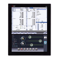
| Category:
Touch Panel
| Size: 3.84 MB
Table of Contents
Manual List
3
Manuals for Mtbs (Drive Section)
4
Manuals for Mtbs (NC)
4
Manuals for Mtbs (Others)
5
Reference Manual for Mtbs
6
For Safe Use
8
Precautions for Safety
8
Caution
9
Disposal
10
Table of Contents
16
Alarm
18
1 Operation Errors (M)
20
Aux Ax Dog Overrun
21
Aux Ax R-Pnt Direction Illegal
21
Aux Ax External Interlock
21
Aux Ax Internal Interlock
21
Some Ax Does Not Pass Z Phase
22
R-Pnt Direction Illegal
22
External Interlock Axis Exists
22
Internal Interlock Axis Exists
22
S/W Stroke End Axis Exists
23
Chuck/Tailstock Stroke End Ax
23
Ref Point Return No. Invalid
23
Illegal Op in MID Pt Sg Block
23
R-Pnt Ret Invld at Abs Pos Alm
24
R-Pnt Ret Invld at Zero Pt Ini
24
High-Accuracy Skip Disabled
24
Hi-Ac Skip Coord Retrieval Err
24
Chopping Axis R-Pnt Incomplete
25
Synchronous Error Excessive
25
No Spindle Select Signal
25
No Spindle Serial Connection
25
Wait for Tap Retract
26
Handle Ratio too Large
26
R-Pos Offset Value Illegal
26
R-Pos Scan Distance Exceeded
26
Illegal Op in Dia/Rad Select
27
No Operation Mode
27
Cutting Override Zero
27
External Feed Rate Zero
27
F 1-Digit Feed Rate Zero
28
Spindle Stop
28
Handle Feed Ax No. Illegal
28
Spindle Rotation Speed over
28
Restart Switch on
29
Program Check Mode
29
Cycle St. in Buffer Correct
29
In Reset Process
29
In Synchronous Correction Mode
30
No Synchronous Control Option
30
Computer Link B Not Possible
30
X/Z Axes Simultaneous Prohibit
30
PLC Interruption Impossible
31
Restart Posn Return Disabled
31
Zero Point Return Interruption
31
Excessive No. of Reverse Block
31
Unable to Start Automatic Mode
32
Tool Data Sorting in Progress
32
Tolerance Control Invalid
32
Ill Manualmode Select in 3Dcnv
32
Chopping Override Zero
33
Command Axis Chopping Axis
33
Bottom Dead Center Pos. Zero
33
Chopping Disable for Handle Ax
33
No Speed Set out of Soft Limit
34
Aux Ax R-Pnt Ret Incomplete
34
Aux Abs Position Initializing
34
Aux Ax Abs Position Error
34
Aux Ax Torque Limit Value Zero
35
Ill. Op During T Tip Control
35
Illegal Op in Spline Interpol2
35
Illegal OP in Tilted Face Cut
35
Rotary Axis para Unswitchable
36
Interference Check Invalidated
36
Machine Interference 1
36
Tool Interfere. Check Disabled
36
Too Many Simul. Control Axes
37
Changing Prg Format Disabled
37
Multi Ax for 3D Manual Feed
37
3D Manual Feed Coord Sys Err
37
Rot Center Err Comp Excessive
38
Unable to Start Measuring Err
38
Invalid Op Mode in Err Measure
38
Machining Surface Operation Disabled
38
No Spec: Spatial Error Comp
39
Spatial Error Comp Excessive
39
Auto Backlash Adjust Illegal
39
Operating Auto Backlash Adjust
39
N/A During High-Cycle Sampling
40
Invalid CMD During Param Write
40
SP Orient. Z Detection Error
40
Illegal Movement Command During Superimposition
40
Superimposition Command Illegal
41
G114.N Command Illegal
41
Spindle In-Use by Synchro Tap
41
GB Spindle Synchro Signal off
41
GB SP Sync:phase Mem Sgnl Ilgl
42
GB SP Sync:phase Set Sgnl Ilgl
42
GB SP Sync:z Phase Not Pass
42
Cmnd Impsbl in Spindle Rtry Ax
42
Thread Recutting Impossible
43
Thread Recutting Data Illegal
43
Variable Speed Thread Disabled
43
Synchronization Mismatch
43
Sp-Sp Polygon Cut Interlock
44
Mixed Sync Ctrl Prmtr Illegal
44
Mixed Sync Ctrl Disable Modal
44
Synchro Ctrl Setting Disable
44
Move Cmnd Invld to Synchro Ax
45
No Spindle Speed Clamp
45
Cont Ax Superimpos II Prm Illg
45
Sync Error Btwn Part Systems
45
Intrf Check Across Sys: Alarm
46
Interfe Chk 0Pt Return Incomp
46
Feed-Forward Control Disabled
46
Superimposition Axis Param Err
46
Cross Control Axis Exists
47
Arbitrary Ax Superimp. Sys Err
47
Spindle Speed Fluctuation
47
Sp Synchro Phase Calc Illegal
47
Sub Part System I Call Error
48
Sub Part System II Start Error
48
Constant Surface Speed Rdndnt
48
Constant Torque Disabled
48
Droop Cancel Disabled
49
Cmnd Disabled in Droop Cancel
49
SP Equivalent Load Factor over
49
Differential Tap Cmnd Disabled
49
Spindle Sync Cancel Error
50
GB SP Sync:cancel Sgnl Illegal
50
GB SP Sync Runs Independently
50
Cmds Illegal in Spindle Synchr
50
Prog Check: Machine Posn Error
51
NC/PLC Axis Switch Illegal
51
No Spec: Multi Axis Synch Ctrl
51
Multiple Secondary Ax Selected
51
Interference Data Unspecified
52
Interf. 3D Objects Count Error
52
Interfere Check III: Time over
52
Interfere: Control Axis Error
52
Interfere:2 Rot Axes Object er
53
Interfere:1 Rot Axis Object er
53
Interf. Selection: Offset over
53
Interf:rot Objects Comb. Error
53
2 Stop Codes (T)
54
Axis in Motion
55
NC Not Ready
55
Reset Signal on
55
Auto Operation Pause Signal on
55
Operation Mode Duplicated
56
Operation Mode Changed
56
Tape Search Execution
56
Cycle Start Prohibit
56
In Absolute Position Alarm
57
In Abs Posn Initial Setting
57
In Manual Measurement
57
Sub Part Sys I Mode Is Active
57
Cycle Start Prohibit (OP Error)
58
Cycle Start Prohibit(SBT Warn)
58
Cycle St. Prohibit (Term Exp'D)
58
Cycle Start Disabled (in SBT)
58
Block Stop Cmnd in User Macro
60
MDI Completed
60
Block Start Interlock
60
Cutting Blck Start Interlock
60
Collation Stop
61
Fin Wait
61
3 Servo/Spindle Alarms (S)
62
Servo Errors (S01/S03/S04)
63
Drive Unit Alarm
64
Encoder Alarm (Servo Drive Unit)
68
Encoder Alarm (Spindle Drive Unit)
69
Dual Signal Error (4D)
70
Power Supply Alarm
72
Initial Parameter Errors (S02)
73
Safety Function Errors (S05)
75
Parameter Errors (S51)
76
Servo Warnings (S52)
77
Drive Unit Warning
78
Dual Signal Warning (A4)
78
Power Supply Warning
79
Safety Function Warnings (S53)
80
4 MCP Alarms (Y)
82
System Alm: Process Time over
83
SV Commu Er: Data ID Error
83
SV Commu Er: Recv Frame No.
83
SV Commu Er: Commu Error
83
SV Commu Er: Connect Error
84
SV Commu Er: Safe Posn FB Err
84
SV Commu er : Init Commu Error
84
SV Commu Er: Node Detect Err
85
SV Commu Er: Commu Not Support
85
Drive Unit Unequipped
85
Mcp_No Setting Error
87
Too Many Drive Units Connected
88
Too Many Axisno Connected
88
No Commu. with Axis Drv Unit
88
No Commu. with Sp Drv Unit
88
RIO Connection Error
89
Parameter Compare Error
89
Sfty Obsrvation: CMD Spd Err
89
Sfty Obsrvation: FB Pos Err
89
Sfty Obsrvation: FB Speed Err
90
Door Signal: Input Mismatch
90
No Speed Observation Mode in Door Open
90
Speed Obsv: para Incompatible
90
Contactor Welding Detected
91
No Spec: Safety Observation
91
SDIO Connector Input Volt Err
91
Device Setting Illegal
92
Contactor Operation Abnormal
92
STO Function Operation Illegal
93
STO Function Illegal at Pwr on
93
Dual Signal: Parameter Setting Error
93
Safety Observation: Parameter Memory Error
93
Parameter G0T1 Illegal
94
Parameter G1T1 Illegal
94
Parameter Grid Space Illegal
94
Parameter Stapt1-4 Illegal
94
OMR-II Parameter Error
95
PLC Indexing Stroke Length Err
95
Hi-Acc Time Const Unextendable
95
Superimpos Linear G0 Error
95
Unable to Alloc. Hi-Acc Buffer
96
Too Many Hi-Speed/Accu Systems
96
Parameter G0Tl_2 Illegal
96
Parameter G0T1_2 Illegal
96
Machine Group No. Discrepancy
97
M-Group Alarm Stop Disabled
97
Basic Axes I, J, K Error
97
Values of PC1/PC2 too Large
97
5 System Alarms (Z)
98
System Error
99
CC-L IE F Communication Error
99
CC-L IE F Parameter Error
99
CC-Link IE F H/W Test Status
99
Network Expansion Card Error
100
PROFIBUS Parameter Error
100
Axis Ex-Adr. Error
100
Unable to Start Safe Spd Clamp
100
Ethernet/Ip Communication Err
101
Socket Open Error(Socket)
101
Socket Bind Error(Bind)
101
Connection Wait Queue Error(Listen)
101
Devicenet Error
102
Direct Socket Connection Error
102
Direct Socket Receive Error
102
Direct Socket Send Error
102
Ecomonitorlight Comm. Error
103
Ecomonitorlight Qty Discrepant
103
Insulation Deterioration Wrn
103
E-Mail Send Error
103
E2PROM Error
104
Battery Fault
104
CNC Overheat
104
RIO Communication Stop
105
System Warning
105
ROM Write Not Completed
105
Acc/Dec Time Cnst too Large
106
Fieldbus Communication Error
106
Valid Term Soon to be Expired
106
Valid Term Has Been Expired
106
External Link Error
107
3D Machine Interference/No Machine Model
108
3D Machine Interference/Machine Model Illegal
108
3D Machine Interference Check Load Excess
108
3D Machine Interference Check Error
108
No Display Conn. to Panel I/O
109
Power on Sequence Error
109
Power off Sequence Error
109
Display Unit Shutoff Timeout
109
Overvoltage Detection Alarm
110
Memory ECC Error
110
6 Absolute Position Detection System Alarms (Z7*)
112
Abs Posn Base Set Incomplete
113
Absolute Position Lost
113
Abs Posn Param Changed
113
Abs Posn Initial Set Illegal
113
Abs Posn Param Restored
114
Abs Posn Data Lost
114
Abs Posn Error(Servo Alm 25)
114
Abs Posn Error(Servo Alm E3)
114
Absencoder: Commu Error
115
Absencoder: Abs Data Changed
115
Absencoder: Serial Data Error
115
Absencoder: Abs/Inc Posn Diffr
115
Battery for Abs Data Fault
116
7 Distance-Coded Reference Scale Errors (Z8*)
118
Basic Position Lost
119
Basic Position Restore
119
No Spec: Distance-Coded Scale
119
R-Pos Adjustment Data Lost
119
8 Emergency Stop Alarms (EMG)
120
Emergency Stop
121
9 Computer Link Errors (L)
124
Timeout Error
125
Host er Signal off
125
Parity H Error
125
Parity V Error
125
10 User PLC Alarms (U)
126
No User PLC
127
Illegal PLC
127
11 Network Service Errors (N)
136
Modem Initial Error
137
Redial over
137
TEL Unconnect
137
Invalid Net Communication
137
Password Error
138
Customer Number Error
138
Storage Capacity over
138
File Deletion Error
138
12 Program Errors (P)
140
No. of Simultaneous Axes over
141
Illegal Axis Address
141
Division Error
141
Not Accept Command
141
Illegal Address
142
Format Error
142
Illegal G Code
142
Setting Value Range over
142
No Specifications
143
Pre-Read Block Error
143
G Code Combination Error
143
Restart Pos Return Incomplete
143
No Spec: Unidirectional Posit.
144
No F Command
144
No Spec: High Speed Mode 3
144
F Value Is Exceeding the Limit
144
No Spec: Herical Cutting
145
No Spec: Spiral Cutting
145
Can't Calculate 3DIM Arc
145
3DIM Arc Illegal
145
Plane Select During Figure Rot
146
Plane Selected While Coord Rot
146
Plane Selected While R Compen
146
Illegal Plane Select
146
No Spec: High-Accuracy Control
147
No Spec: Inverse Time Feed
147
G93 Mode Error
147
Invalid Cmnd in High-Accuracy
147
No Spec: Cnst Surface Ctrl G96
148
Spindle Rotation Speed S=0
148
Illegal P-No. G96
148
G96 Clamp Err.
148
Radius Compen During Arc Mode
149
No Intersection
149
Compensation Interference
149
No Spec: 3D Compensation
149
Illegal Tip Point
150
No Spec: 3D Tool R Comp
150
Disable CMD in 3D Tool R Comp
150
3D Tool R Comp Is Disabled
150
G10 P Number Error
151
No Spec:comp Input by Prog G11
151
Tool Life Count Active
151
Tool Life Data Entry over
151
Synchronous Tap Error
152
No Pitch/Thread Number
152
Pitch/Thread Number Error
152
No Spec: Sync Tapping Cycle
152
Tool Selection Is Incorrect
153
No Spec: MRC Cycle
153
Program Error (MRC)
153
Block over (MRC)
153
No Spec: Special Fixed Cycle
154
No. of Special Fixed Holes = 0
154
G36 Angle Error
154
G12/G13 Radius Error
154
Program Editing
155
No Spec: Variable Commands
155
No Variable No.
155
Can't Use Variables
155
No Spec: Figure Rotation
156
Figure Rotation Overlapped
156
Coord Rotate in Fig. Rotation
156
No Spec: Coordinates Rotation
156
Macro Call Nesting over
157
Macro Argument over
157
Illegal G67 Command
157
Macro Alarm Message
157
If-Endif MMC.
158
IF Sentence Error
158
WHILE Sentence Error
158
SETVN Sentence Error
158
Address-A Error
159
G200-G202 Cmnd in Tape
159
Variable Name Illegal
159
Variable Name Duplicated
159
Facing T-Post MR Illegal
160
No Spec: Corner R/C
160
No Spec: Arc R/C
160
No Corner Movement
160
No Spec: Geometric Arc
161
Inc Value in 2Nd Block (GEOMT)
161
No Linear Move Command (GEOMT)
161
Illegal Address (GEOMT)
161
Illegal Modal G111
162
No Spec: Axis Name Switch
162
No Spec: para Input by Program
162
Parameter Input Error
162
R-Navi Input Error
163
R-Pnt Return Incomplete
163
No Spec: 2,3,4Th R-Point Ret
163
No Spec: Start Position Return
163
G29 and M Commands in a Block
164
G52 Invalid During G54.1
164
No Spec: Chuck Barrier
164
No Spec: Stroke Chk Bef Travel
164
No Spec: Milling
165
Illegal G Code (Mill)
165
Illegal Axis (Mill)
165
R-Pnt Ret Incomplete (Mill)
165
Illegal Modal (Mill)
166
Milling Error
166
Cross (G110) Impossible
167
Illegal G110 Axis
167
Synchronization M Code Error
167
Control Axis Superimposition/Designated Axis Illegal
167
Illegal Synchronization Axis
168
No Spec: Wk Instl Err Cmp
168
Invld CMD in Wk Instl Err Cmp
168
Wk Instl Err Cmp CMD Invalid
168
Invld Manual Interrupt in G6.2
169
Invalid Restart During G06.2
169
Fairing Changeover Disabled
169
Skip Axis Illegal
169
TLM Illegal Axis
170
T & TLM Command in a Block
170
T Cmnd Not Found before TLM
170
TLM Illegal Signal
170
Exponential Function Error
171
Sub Sys Identification # Error
171
Other G Code in Sub Sys Block
171
Illegal Mode (Sub Part System)
171
PLC Device too Much
172
Illegal Command Value
172
Dia/Rad Selection CMD Invalid
172
Invld CMD in Dia/Rad Selection
172
Proceed of Prog Check Disabled
173
No Spec: Normal Line Control
173
Normal Line Control Axis G92
173
Normal Line Control Axis Error
173
Illegal Addr in 3D Coord Blk
174
Travel CMD Error in 3Dconvert
174
End Point Err in 3D Conversion
174
No Spec: Tool Axis Compen
174
Invalid T Tip Control Command
175
Invalid Cmnd During T Tip Ctrl
175
Tool Posture Command Illegal
175
No Spec: Tilt Face Machining
175
Inclined Face Coord Illegal
176
G68.2P10 Surface Not Defined
176
Tool Axis dir Ctrl Cmp Amt 0
176
Tool Axis dir Ctrl Axis Illeg
176
Illegal Direct Cmnd Mode Cmnd
177
PREPRO Error
177
13 Smart Safety Observation Alarm (V)
178
Smart Safety Observation Error (V01/V02/V03/V04/V05/V06/V07)
179
Safety Watchdog Error
179
Cross-Check Error
179
Safe Sys Internal Process Err
179
NC-DRV Initial Safe Comm Error
180
Safe IO Init. Process Timeout
180
Encoder Error
180
NC-DRV Safe Communication Err
180
Slave Station Data Compare Err
181
Output off Check Error
181
Output Signal Cross-Check Err
182
Transmission Cross-Check Error
182
Reception Cross-Check Error
182
Host Station Comm. Error 1
183
Host Station Comm. Error 2
183
Drv Safe Receive Crosscheck er
183
User Safety Sequence 1 Error
183
User Safety Sequence 2 Error
184
Output Sig. Cross Check Error
184
Safety Observation & Smart both on
184
Safety IO Device Unconnectable
184
Safe IO Disabled: Connect Err
185
Safe IO Disabled: no Safe I/Os
185
Safety PLC Is Not yet Written
185
NC-DRV Safety Comm. Disabled
185
EMG Stop Signal Device Illegal
186
Safe IO Assign para Setting er
186
Safety I/O Param Inconsistent
186
SLS Speed Error
186
SLS Deceleration Error
187
SLP Position Error
187
SOS Speed Error
187
SOS Position Deviation Error
187
SOS Travel Distance Error
188
SS1 Deceleration Error
188
SS2 Deceleration Error
188
Safety External EMG Stop Is on
188
Smart Safety Observation Warning (V50/V51/V52/V53/V54)
189
SSM Hysteresis Setting Error
189
Safe Absol. Posn Unestablished
189
SBT Start Disabled
189
SBT Warning 4
190
SBT Warning 5
190
SBT Warning 6
190
PLC Safety Stop Is Active
190
Warning on 24Hr Continuous on
191
Simple Test Mode Is Active
191
14 Multi CPU Errors (A) [C80]
192
Power Shutoff
193
ROM Write Count Error
193
Default Gateway/Gw IP Address Error
193
Own Node Port Number Error
193
Socket Comm. Response Send Error
194
TCP Connection Timeout
194
IP Address Error
194
Connection Number Acquisition Error
194
Parameter
194
TCP/IP Send Failed
195
Unsend Data Send Error
195
Module Moderate Error
195
Parameter
195
Multiple CPU Synchronization Processing Error
196
Receive Queue Full
196
Receive Processing Error
196
Transient Data Error
196
Parameter
196
Module Configuration Error
197
Parameter
197
CPU Module Configuration Error
198
Parameter
198
Base Unit a Configuration Error
199
Inter-Module Synch Configure Error
199
Parameter
199
Module Unrecognized
200
IP Address Duplication Error
200
Invalid File
200
File Specification Error
200
Parameter
200
Parameter a Error
201
Parameter Error (Module)
202
Parameter Error (Network)
202
Parameter
203
Parameter Verification Error
204
Security Key Authentication Error
204
Remote a Password Setting Error
204
Module Verification Error
205
Fuse Blown Error
205
Module Major Error
205
Parameter
205
Another CPU Module Major Error
206
Multiple CPU Error
206
Parameter
206
System Bus Error
207
Parameter
207
Parameter
208
WDT Error
209
Invalid Interrupt
209
Inter-Module Synch Signal Error
209
Parameter
209
Multiple CPU Synch Signal Error
210
Boot Function Execution Error
210
Parameter
210
Pointer Setting Error
211
Interrupt Pointer Setting Error
211
Parameter
211
Hardware Failure
212
Parameter
212
Parameter
213
Parameter
214
Parameter
215
Parameter
216
Parameter
217
Advertisement
Mitsubishi Electric C80 Series Instruction Manual (460 pages)
Brand:
Mitsubishi Electric
| Category:
Control Systems
| Size: 6.11 MB
Table of Contents
Table of Contents
22
1 Outline of Menu Items
26
2 Screen Operations
32
Graphic Operation Terminal (GOT)
33
Screen Operation of GOT
33
Explanations of the Screens
34
Messages
38
External Memory Interface
39
CNC Monitor2 Screen
40
Displayed Part System
42
NC Status
43
Operation Mode/MDI Status
44
Operation Status
44
Alarms/Warnings
45
Operation Messages
45
Changing the Screen Theme Color
46
Screen Transition Diagram
47
Setting Data
48
Setting Numerals and Alphabetical Characters
48
Inputting Operations
49
Guidance Function
51
Parameter Guidance
51
Alarm Guidance
53
G Code Guidance
56
Menu List
59
Touchscreen Functions
61
Basic Operation
61
Software Keyboard
63
Operating the Screen by Touch Gestures
67
Menu Customization Function
71
Changing the Operation Level (Protect Setting Screen)
73
3 Inputting a Machining Program and Defining Variables
74
Inputting a Machining Program
75
Creating and Editing a Machining Program
75
Registering and Editing the MDI Program
83
Registering and Editing the Fixed Cycle Program
85
Fixed Cycle Operation Parameters
85
Transmitting and Erasing the Fixed Cycle Program
85
Erasing a File
86
Editing Operations
87
Changing the Display
87
Displaying an Arbitrary Line
89
Rewriting Data
89
Inserting Data (Initial Data Overwrite Mode)
90
Overwriting Data (Initial Data Insertion Mode)
91
Deleting Data
91
Searching for Character Strings
93
Replacing Character Strings
95
Copying and Pasting Data
96
Undoing Program Changes
98
Program Editing Support Function
99
Performing Operation Search at the Cursor Position
99
Adding Sequence No. (N No.) Automatically
100
G Code Guidance
101
Playback Editing
102
Editing a Multi-Part System Program
106
Multi-Part System Simultaneous Program Editing
106
Special Program Editing Display for Synchronization between Part Systems
112
Defining Variables
113
Common Variables
113
Local Variables
118
4 Inputting and Outputting a Machining Program
122
Inputting and Outputting a Program
123
Selecting a Device, Directory and File
127
Transferring a File
130
Comparing Files (Compare)
133
Erasing a File
134
Changing a File Name (Rename)
135
Creating a Directory
136
Other Functions
137
Merging a File
137
List of File Names
138
Edit Lock B and C
138
Program Display Lock
139
Data Protection Keys
139
Leading Zero
140
The Batch Input/Output the Machining Program of NC Memory
141
5 Setting a Tool and a Workpiece
146
Setting a Tool
147
Registering a Tool (Tool Registration Screen)
147
Registering a Tool in the Magazine Pot
149
Setting the PLC Command
149
Setting and Erasing the Tool No. of Spindle/Standby Tools
150
Erasing the Tool Registration Data
150
Measuring a Tool (Tool Measurement Screen)
151
Tool Measurement (M System)
151
Tool Measurement (L System)
156
Setting Tool Compensation Amount (Tool Offset Screen)
167
Setting the Tool Compensation Data
174
Switching the Input Method for the Tool Compensation Data
176
Erasing the Tool Compensation Data
177
Copying and Pasting the Tool Compensation Data
178
Undoing Change of Tool Compensation Data
178
Disabling the Setting of Tool Compensation Amount
179
Measuring Tool Compensation Amount
180
Moving to Designated Compensation Number
182
Setting the Tool Management Data (Tool Management Screen)
183
List of Display Items
185
Data Setting Range
190
Menu Configuration
194
Registering New Tool Management Data
198
Switching the Item Type of the Tool Management Data Detailed Portion
198
Displaying Data by Designating Tool Management Data no
199
Displaying Data by Designating Tool no
200
Sorting the Data by Tool no
201
Deleting the Tool Management Data
202
Copying and Pasting the Tool Management Data
203
Specifying Display Format and Setting Range of Additional Information
205
Tool Life Management
206
Displaying the Group List (M System: Tool Life Management I, II / L System: Tool Life Management II)
208
Displaying the Life Management Data in Group Units (M System)
212
Displaying the Life Management Data (L System: Tool Life Management I)
220
Displaying the Tool Life Management Data in Group Units (L System: Tool Life Management II)
222
Setting and Measuring a Workpiece
227
Workpiece Measurement (M System)
227
Carrying out Surface Measurement
231
Carrying out Hole Measurement
232
Carrying out Width Measurement
234
Carrying out Rotation Measurement
236
Performing Automatic Recontact When Contacting the Workpiece
239
Workpiece Measurement (L System)
240
Setting Workpiece Coordinate System Offset
246
Setting the Coordinate System Offset Amount
248
Erasing the Coordinate System Offset Amount
249
Setting the Workpiece Coordinate Origin
249
Changing the Coordinate System Display
250
Setting Workpiece Coordinate System Shift
251
Manually Setting the Workpiece Coordinate System Shift Value
255
Automatically Setting the Workpiece Coordinate System Shift Value
257
Mitsubishi Electric C80 Series Connection And Set Up Manual (304 pages)
Brand:
Mitsubishi Electric
| Category:
Control Systems
| Size: 14.66 MB
Table of Contents
Table of Contents
28
1 System Basic Configuration
32
System Basic Configuration Drawing
33
2 General Connection Diagram
34
3 List of Configuration
36
CNC Control Unit
37
Got
47
Gt27
47
Gt25
49
Peripheral Device
50
Dual Signal Module
50
List of Q Series Units (for RQ Extension Base Unit)
51
4 General Specifications
54
Installation Environment Conditions
55
Base Unit
56
Basic Base Unit
56
Extension Base Unit
57
RQ Extension Base Unit
59
Power Supply
60
R61P/R62P/R63P/R64P
60
Q61P/Q63P/Q64Pn
64
Plc Cpu
69
CNC CPU Module
74
Dual Signal Module
78
Signal Splitter
83
Manual Pulse Generator
85
Manual Pulse Generator (UFO-01-2Z9)
85
Manual Pulse Generator (HD60C)
86
Recommended Terminal Block for Dual Signal Module
86
GOT (Panel Cut Dimensions)
87
5 Installation
88
Module Installation
89
Precautions for Handling
89
Precautions for Installation of Basic Base Unit
92
Module Installation and Removal
94
Installation and Removal the Signal Splitter
97
Calculating Heat Generation by C80
99
6 Wiring and Connecting
102
Precautions
103
Precautions for Power Supply Wiring
103
Precautions for Wiring of I/O Equipment
104
Precautions for Grounding
104
Precautions for Using Optical Communication Cable
105
Wiring to the Power Supply Module
107
R61P/R62P/R63P/R64P
107
Q61P/Q63P/Q64Pn
108
Connecting the Emergency Stop Signal
109
Connecting the GOT
110
Connecting the Drive Unit
111
Connecting the Dual Signal Module
112
Connecting the Signal Splitter
113
Connecting the Skip Signal (Sensor)
114
Connecting the Manual Pulse Generator
115
7 Cable
118
Symbols for Writing Cable Drawings
119
Cables for CNC CPU
120
F020/F021/F022 Cable
120
G020/G021/G022 Cable
121
H010 Cable
122
H101 Cable
123
H300 Cable
124
H310 Cable
125
H401 Cable
126
H501 Cable
126
J303 Cable
127
Cable Relating to Drive Unit
128
Cable Wire and Assembly
128
CNP2E-1 Cable
129
CNP3EZ-2P/CNP3EZ-3P Cable
130
CNV2E-8P/CNV2E-9P Cable
131
CNV2E-D Cable
132
CNV2E-HP Cable
133
DG30 Cable
134
G380 Cable
135
J395 Cable
136
J396 Cable
137
MR-BKS1CBL-A1-H / MR-BKS1CBL-A2-H Cable
138
MR-BT6V2CBL Cable
138
MR-D05UDL3M-B Cable
139
MR-PWS1CBL-A1-H / MR-PWS1CBL-A2-H Cable
139
SH21 Cable
140
8 Setup Outline
142
Flow of the Initial Setup
143
9 GOT Initial Setup
144
GT Designer3
145
Installing GT Designer3
145
Making Communication Settings
146
Setting Ethernet Connection
146
Setting the Saving Destination Drive for Backup Data
153
Setting Time on GOT
155
Creating a GOT Screen
157
Precautions for Device Settings
157
Special Function Switch
158
Writing the Package Data to GOT
159
10 PLC CPU Initial Setup
164
GX Works3
165
Connecting the Devices Necessary for Setup
165
Setting the Connection to GX Works3
166
Setting Multi-CPU Parameters
168
Writing the Created Parameters to the PLC
179
Advertisement
Mitsubishi Electric C80 Series Maintenance Manual (162 pages)
Brand:
Mitsubishi Electric
| Category:
Controller
| Size: 7.08 MB
Table of Contents
Table of Contents
28
1 System Basic Configuration
30
System Basic Configuration Drawing
31
General Connection Diagram
32
How to Check the System Configuration
33
System Configuration Screen
33
Option Display Screen
34
Each Unit Status Display
35
Power Supply
35
R61P/R62P/R63P/R64P
35
Q61P/Q63P/Q64Pn
36
PLC CPU Module
37
CNC CPU Module
39
2 Daily Maintenance and Periodic Maintenance
40
Daily Maintenance
41
Got
41
Periodic Maintenance
41
3 Maintenance of the Drive Unit
42
Periodic Inspections
43
Durable Parts
44
Adding and Replacing Units and Parts
45
MDS-E/EH Series
45
Replacing the Drive Unit
45
Replacing the Unit Fan
46
Replacing the Battery
48
MDS-EJ/EJH Series
51
Replacing the Drive Unit
51
Replacing the Unit Fan
51
Replacing the Battery
57
MDS-EM/EMH Series
60
Replacing the Drive Unit
60
Replacing the Fan Unit
61
Replacing the Battery
62
4 Failure Diagnosis
66
Introduction
67
Failure Diagnosis Procedure
67
Diagnosis Based on the Alarm
68
How to Check the Alarm Information
68
Alarm History
70
Alarm Message Details
72
Diagnosis Based on the I/F Diagnosis Screen
73
I/F Diagnosis Screen
73
Displaying the PLC Device Data
75
Carrying out Modal Output
76
Carrying out One-Shot Output
77
List of Devices for PLC Uses
78
Diagnosis Based on the Self Diagnosis Screen
79
Self Diagnosis Screen
79
Diagnosis Based on the Data Sampling Screen
82
Diagnosis Based on the Drive Monitor Screen
83
Drive Monitor Screen (Servo Unit)
83
Drive Monitor Screen (Spindle Unit)
88
Drive Monitor Screen (Power Supply Unit)
93
Drive Monitor Screen (Synchronous Error)
95
Clearing the Alarm History on Drive Monitor Screen
96
NC Memory Diagnosis Screen
97
Safety Observation Screen
99
Safety Observation Screen (Configuration Diagnosis)
99
Safety Observation Screen (Signal Monitor)
101
Safety Observation Screen (Drive Monitor)
103
Safety Observation Screen (Version Display)
106
Servo Diagnosis Screen
107
Diagnosis Data Collection Setting
110
Starting the Data Collection
112
Stopping the Data Collection
112
Clearing the Collected Data
113
Referring to the Collected Data
113
Advertisement
Related Products
Mitsubishi Electric CMB-1013
Mitsubishi Electric CMB-WP-V-GA1
Mitsubishi Electric CITY MULTI PQHY-P-YEM-A Series
Mitsubishi Electric CAHV-R450YA-HPB-BS
Mitsubishi Electric CITY MULTI PUHY-HP-TJMU-A-BS
Mitsubishi Electric CITY MULTI PURY-P-YHMU-A-BS
Mitsubishi Electric CITY MULTI PQHY-P-TSLMU-A
Mitsubishi Electric CITY MULTI PUHY-P-ZKMU-A
Mitsubishi Electric CITY MULTI PUHY-P-YJMU-A-BS
Mitsubishi Electric CITY MULTI PEFY-P-VMR-E-R Series
Mitsubishi Electric Categories
Air Conditioner
Controller
Projector
Inverter
Heat Pump
More Mitsubishi Electric Manuals
Login
Sign In
OR
Sign in with Facebook
Sign in with Google
Upload manual
Upload from disk
Upload from URL