Sign In
Upload
Manuals
Brands
Keysight Manuals
Measuring Instruments
N9038A
User Manuals: Keysight N9038A EMI Test Receiver
Manuals and User Guides for Keysight N9038A EMI Test Receiver. We have
9
Keysight N9038A EMI Test Receiver manuals available for free PDF download: Service Manual, Measurement Manual, Manual, Installation Note, Demo Manual
Keysight N9038A Service Manual (745 pages)
MXE EMI Receiver
Brand:
Keysight
| Category:
Receiver
| Size: 26 MB
Table of Contents
1. Overview
5
Table of Contents
5
1 Overview
17
What You will Find in this Chapter
17
Service Manual Revision History
18
Keysight MXE EMI Receiver Overview
20
Virus Information
20
Instrument Option Descriptions
21
Before You Start Troubleshooting
23
General Safety Considerations
24
ESD Information
26
Protection from Electrostatic Discharge
26
Handling of Electronic Components and ESD
27
Test Equipment Usage and ESD
27
For Additional Information about ESD
27
Service Equipment You will Need
28
Tools You will Need
28
Calibration Application Software
29
Front End Controller Troubleshooting Kit
30
Type-M Troubleshooting Cable
30
After an Instrument Repair
31
Contacting Keysight Technologies
31
Instrument Serial Numbers
34
How to Return Your Instrument for Service
35
Service Order Number
35
Original Packaging
35
Other Packaging
36
2 Boot up and Initialization
37
What You will Find in this Chapter
37
Check the Basics
38
MXE Instrument Boot up Process
39
Typical Instrument Boot-Up Process Flow
40
Potential Problems During Boot Process
43
Yellow Standby LED Does Not Illuminate
43
Green Power on LED Does Not Illuminate
45
Fan(S) Are Not Operating
49
No Keysight Splash Screen Displayed
52
Instrument Hangs at the Keysight Splash Screen
53
Instrument Cannot Completely Load or Run the Operating System
54
Troubleshooting a Blank Display
54
Verify LCD Backlight Functionality
55
Verify Video Signal Path Integrity
58
Video Controller / LCD Troubleshooting
58
Initializations DID Not Complete
59
Fails an Initial Alignment
59
Signal Level Verification
63
3 Instrument Messages
67
Introduction
67
Event Vs. Condition Messages
67
Event and Condition Categories
68
Event Message Format
70
Event Queues
70
Advisory Messages
72
Event Messages
77
800, Operation Complete Event
78
700, Request Control Event
78
600, User Request Event
78
500, Power on Event
78
-400 to -499, Query Errors
78
-300 to -399, Device-Specific Errors
79
-221 Settings Conflict Errors
82
-200 to -299, Execution Errors
95
-100 to -199, Command Errors
105
Error
107
Condition Messages
108
Condition Errors 1 to 99, Calibration
108
Condition Errors 101 to 199, Measurement Integrity
113
Condition Errors 201 to 299, Signal Integrity
116
Condition Errors 301 to 399, Uncalibrated Integrity
120
Condition Errors 401 to 499, Power
124
Condition Errors 501 to 599, Frequency
125
Condition Errors 601 to 699, Error Summaries
126
Condition Errors 701 to 799, Operation
127
Condition Errors 801 to 899, Temperature
129
4 Input Selection & Level Control
131
What You will Find in this Chapter
131
Input Selection & Level Control Section Purpose
132
Input Selection & Level Control Section Description
132
Input Selection & Level Control Assembly Descriptions
133
A9 Input Attenuator a
133
A10 Attenuator B
133
A23 Limiter Assembly
134
SW1 Cal Switch
135
SW2 Transfer Switch
135
Input Selection & Level Control Section Troubleshooting
136
A9 Attenuator a
136
A10 Attenuator B
136
A10 Attenuator B
145
A23 Limiter Assembly
149
SW1 Cal Switch
155
SW2 Transfer Switch
159
5 Rf Preselector Section
163
5 RF Preselector Section
164
RF Preselector Section Purpose
164
RF Preselector Section Description
164
RF Preselector Section Signal Paths
164
RF Preselector Section Assembly Descriptions
166
A21 RF Preselector Input Assembly
166
A22 Radiated Filter Assembly
170
A24 Conducted Filter Assembly
173
RF Preselector Section Troubleshooting
175
A21 RF Preselector Input Assembly
175
A22 Radiated Filter Assembly
175
A24 Conducted Filter Assembly
175
A22 Radiated Filter Assembly
194
A24 Conducted Filter Assembly
204
6 Rf Downconverter Section
217
What You will Find in this Chapter
217
RF Downconverter Section Description
218
RF Section Purpose
218
RF Section Signal Paths
220
RF Section Assembly Descriptions
225
RF Downconverter Section Troubleshooting
233
A11 RF Switch / High Band Preamp
233
A12 YTF Preselector
242
A13 RF Front End Assembly
252
7 L.O. Synthesizer
261
What You will Find in this Chapter
261
A14 L.O. Synthesizer Assembly Description
262
A14 L.O. Synthesizer Purpose
262
A14 L.O. Synthesizer Description
262
A14 L.O. Synthesizer Assembly Connections
263
A14 L.O. Synthesizer Assembly Troubleshooting
264
Assembly Initialization
264
Assembly Status Leds
265
Frequency and Amplitude of the 1St lo Output
266
8 Front End Control
269
What You will Find in this Chapter
269
A15 Front End Control Description
270
A15 Front End Control Purpose
270
A15 Front End Control Assembly Description
270
A15 Front End Control Assembly Connections
271
A15 Front End Control Assembly Troubleshooting
274
Assembly Initialization
274
Assembly Control Verification - (Option 503, 508, & 526 Only)
275
A9 Input Attenuator a Control - (Option 503, 508, & 526 Only)
277
A10 Input Attenuator B Control - (Option 503, 508, & 526 Only)
281
A11 RF Switch / High Band Preamp Control - (Option 503, 508, & 526 Only)
284
A12 YTF Preselector Control - (Option 508 & 526 Only)
288
A12 YTF Preselector Alignment
291
A13 RF Front End Assembly Control - (Option 503, 508, & 526 Only)
292
IF Switching
297
AUX if Output (Option CR3)
302
9 Reference Assembly
305
A16 Reference Assembly Description
306
A16 Reference Assembly Purpose
306
A16 Reference Assembly Description
307
A16 Reference Assembly Connections
307
A16 Reference Assembly Troubleshooting
309
Assembly Initialization
309
Assembly Status Leds
309
Assembly Output Signal Frequency & Amplitude Verification
311
Digital if Reference (10 Mhz)
312
50 Mhz Calibrator
313
E-Cal Reference
314
Digital if Reference (100 Mhz)
315
3Rd lo
316
4.8 Ghz Calibrator
317
1St lo Reference
318
2Nd lo (Low Band)
319
Wideband if Reference
320
10 Analog & Digital if
321
What You will Find in this Chapter
321
A2 Analog if Assembly Description
322
A2 Analog if Assembly Purpose
322
Overall A2 Analog if Assembly Resolution Bandwidth
324
A2 Analog if Assembly Connections
325
A2 Analog I.F. Troubleshooting
326
Assembly Initialization
326
Signal Path Verification
326
A2 Analog if Filter Path Switching
327
A2 Analog if Filter Path Passband Shape
330
A2 Analog if 25 Mhz Filter Path (Option B25 Only)
335
A3 Digital I.F. Assembly Description
337
A3 Digital if Assembly Purpose
337
A3 Digital if Assembly Description
338
A3 Digital if Assembly Connections
339
A3 Digital I.F. Troubleshooting
342
Assembly Initialization
342
Assembly Functionality Verification
343
22.5 Mhz if Signal Processing
344
10 Mhz Reference Output
345
Trigger Outputs
346
Trigger Inputs
347
Analog Output (Option YAS Only)
348
Noise Source Output (Optional N9069A Software Required)
350
Smart Noise Source Interface (Optional N9069A Software Required)
351
11 CPU & Disk Drive
355
What You will Find in this Chapter
355
A4 Processor Assembly Description
356
Disk Drive
356
A4A1 Disk Drive Interface Board
356
Front Panel Interface
356
Graphics Controller
356
Power Supply Control
357
Rear Panel Connectivity
357
System Memory
358
System Processor
358
Processor Battery
358
SD Memory Card Slot
358
A4 Processor Board Assembly Troubleshooting
359
Boot-Up or Initialization Problems
359
BIOS Settings
359
A5 Disk Drive
360
Overview
361
Troubleshooting Software Related Issues
362
Reloading the Instrument Application Software
363
Disk Drive Recovery Process
364
Instrument Image Recovery System
364
Using the Instrument Recovery System
365
Replacing the Instrument Disk Drive
366
12 Power Supply & Midplane
367
What You will Find in this Chapter
367
A6 Power Supply Description
368
A6 Power Supply Purpose
368
A6 Power Supply Assembly Troubleshooting
371
Supply Voltages
371
Control Inputs
371
Status Outputs
371
A7 Midplane Board Assembly Description
373
A7 Midplane Assembly Purpose
373
A7 Midplane Assembly Description
373
A7 Midplane Assembly Connections
374
A7 Midplane Board Assembly Troubleshooting
375
Instrument Power Supply Leds and Test Points
375
Additional Power Supply Regulation
375
Instrument Secure Storage
375
Power Supply Dithering
375
13 Motherboard & Front Panel
379
What You will Find in this Chapter
379
A8 Motherboard Assembly Description
380
A8 Motherboard Assembly Purpose
380
A8 Motherboard Assembly Connections
380
A1 Front Panel Assembly
382
A1A2 Front Panel Interface Board
382
A1A3 Lcd
382
A1A4 Backlight Power Supply
382
A1A5 Front Panel Daughter Board
382
14 Optional Assemblies
383
What You will Find in this Chapter
383
A25 Wideband Analog if Assembly Description
384
A25 Wideband Analog if Assembly Purpose
384
A25 Wideband Analog if Assembly Troubleshooting
387
Assembly Initialization
387
Overall Wideband Signal Path Verification
388
2400 Mhz Reference Input Verification
389
Input Signal Level Verification
390
Input Switching Verification
391
A26 Wideband Digital if Assembly Description
393
A26 Wideband Digital if Assembly Purpose
393
A26 Wideband Digital if Assembly Connections
395
A26 Wideband Digital if Assembly Troubleshooting
396
Assembly Initialization
396
Internal Alignment Failures
397
Overall Wideband Signal Path Verification
397
A30 LISN Control Assembly Description
399
A30 LISN Control Assembly Purpose
399
A30 LISN Control Assembly Connections
399
A30 LISN Control Assembly Troubleshooting
401
Assembly Initialization
401
Option LSN License Key
401
Output Data Line Status Leds
402
Rear Panel AUX I/O Outputs
403
15 Block Diagrams
405
What You will Find in this Chapter
405
Block Diagrams
407
N9038A RF Input Option 503, 508, 526 Block Diagram
407
N9038A RF Input Option 544 Block Diagram
408
LO Synthesizer Block Diagram
428
Reference Block Diagram
429
MXE Computer Block Diagram
430
16 Service and Diagnostics Menus
432
Overview
432
Controlling Access
432
Secure Service Access
433
Service Menus
434
Service Key Descriptions
441
Service
441
Timebase
442
Corrections
443
Lock Functions
444
LO Control
445
Align
445
Diagnostics
448
RF Preselector
448
AUX I/O Control
454
Diagnostics Key Description
455
17 Replaceable Parts
456
What You will Find in this Chapter
456
How to Order Parts
457
Replaceable Parts
458
Hardware
476
18 Assembly Replacement Procedures
508
What You will Find in this Chapter
508
Before Starting
510
Safety
510
Tools You will Need
511
Adjustments Tests after an Instrument Repair
511
Major Assembly Locations
512
Instrument Outer Case
513
Removal
513
Replacement
514
Top Brace and Power Supply Bracket
515
Removal
515
Replacement
516
RF Area - Option 503, 508, & 526
517
Attenuators - Option 503, 508, & 526
518
RF Switch/High Band Preamp Assembly - Option 503, 508, & 526
521
YTF Preselector - Option 503, 508, & 526
525
Cal Switch and Transfer Switch - Option 503, 508, & 526
528
Attenuators - Option 544
538
RF Switch/High Band Preamp Assembly - Option 544
541
YTF Preselector - Option 544
544
Cal Switch and Transfer Switch - Option 544
547
RF Front End Assembly
551
Removal
551
Replacement
553
Limiter Assembly
554
Removal
554
Replacement
555
Front End Control Assembly
556
Removal
556
Replacement
557
LO Synthesizer Assembly
558
Removal
558
Replacement
559
Radiated Filter Assembly
560
Removal
560
Replacement
561
RF Preselector Input Assembly
562
Removal
562
Replacement
562
Conducted Filter Assembly
563
Removal
563
Replacement
563
LISN Control Assembly
564
Removal
564
Replacement
565
Wideband Analog if and Wideband Digital if Assemblies
566
Removal
566
Replacement
567
Reference Assembly
568
Removal
568
Replacement
569
Midplane Board Assembly
570
Removal
570
Replacement
571
Rear Panel
572
Removal
572
Replacement
573
Power Supply Assembly
574
Removal
574
Replacement
575
CPU Assembly
576
Removal
576
Replacement
576
Disk Drive
577
Drive Removal and Replacement
577
Disk Drive Interconnect
581
AIF/DIF Assembly
583
Removal
583
Separate AIF/DIF Assembly
585
Replacement
586
Motherboard Assembly
587
Removal
587
Replacement
591
W35 Removal
594
Fan Assembly
595
Removal
595
Replacement
598
Input Connector Assembly
599
RF Input 1 Connector
599
RF Input 2 Connector
601
Front Frame Assembly
603
Removal
603
Replacement
605
Front Frame Assembly Components - LED
606
Front Frame Assembly Components - CCFL Backlight
614
Input 2 LED Board
623
19 Post-Repair Procedures
624
What You will Find in this Chapter
624
Before Starting
624
Calibration Data Backup and Restore
628
20 Instrument Software
640
What You will Find in this Chapter
640
Instrument Software Overview
641
Software Licensing
641
Software Updates
642
Instrument Measurement Application Software
642
21 Performance Verification and Adjustment Software
644
Test Software Overview
644
Performance Verification Tests
644
Adjustments
644
Required Test Equipment
645
22 Tests
647
Functional Test Versus Performance Verification
647
Before Performing a Functional Test
648
Test Equipment
649
Displayed Average Noise Level (DANL)
652
Procedure
653
Frequency Readout Accuracy
656
Procedure
657
Second Harmonic Distortion (SHD)
659
Procedure
660
Amplitude Accuracy at 50 Mhz
662
Procedure
663
Amplitude Accuracy - Preamp on
667
Procedure
668
Frequency Response (Flatness)
671
Procedure
672
Frequency Response (Flatness) - Preamp on
677
Procedure
678
Scale Fidelity
683
Procedure
684
CISPR Resolution Bandwidth Shape Accuracy
686
Procedure
687
Quasi-Peak Detector Accuracy
690
Sine Wave Generator Characterization
691
Initial Setup
692
Band a Testing
692
Band B Testing
694
Band C Testing
697
Band D Testing
700
Peak Detector Accuracy
704
Sine Wave Generator Characterization
705
Initial Setup
706
Band a Testing
706
Band B Testing
708
Band C Testing
710
Band D Testing
712
EMI Average Detector Accuracy
714
Sine Wave Generator Characterization
715
Initial Setup
716
Band a Testing
716
Band B Testing
718
Band C Testing
720
Band D Testing
723
RMS Average Detector Accuracy
725
Sine Wave Generator Characterization
726
Initial Setup
727
Band a Testing
727
Band B Testing
729
Band C Testing
731
Band D Testing
734
Intermittent, Unsteady, Drifting Disturbances
736
Initial Setup
737
EMI Average Detector Testing
737
RMS Average Detector Testing
739
Advertisement
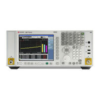
Keysight N9038A Measurement Manual (225 pages)
Signal Analyzer Spectrum Analyzer Mode
Brand:
Keysight
| Category:
Measuring Instruments
| Size: 7 MB
Table of Contents
Table of Contents
5
Getting Started with the Spectrum Analyzer Measurement Application
12
Making a Basic Measurement
12
Using the Front Panel
12
Presetting the Signal Analyzer
13
Viewing a Signal
14
Recommended Test Equipment
17
Accessories Available
18
50 Ohm Load
18
50 Ohm/75 Ohm Minimum Loss Pad
18
75 Ohm Matching Transformer
18
AC Probe
18
AC Probe (Low Frequency)
19
Broadband Preamplifiers and Power Amplifiers
19
GPIB Cable
19
USB/GPIB Cable
19
RF and Transient Limiters
19
Power Splitters
20
Static Safety Accessories
20
Measuring Multiple Signals
21
Comparing Signals on the same Screen Using Marker Delta
22
Comparing Signals Not on the same Screen Using Marker Delta
25
Resolving Signals of Equal Amplitude
28
Resolving Small Signals Hidden by Large Signals
33
Decreasing the Frequency Span Around the Signal
37
Easily Measure Varying Levels of Modulated Power Compared to a Reference
39
Measuring a Low−Level Signal
43
Reducing Input Attenuation
44
Decreasing the Resolution Bandwidth
47
Using the Average Detector and Increased Sweep Time
50
Trace Averaging
52
Improving Frequency Resolution and Accuracy
55
Using a Frequency Counter to Improve Frequency Resolution and Accuracy
56
Tracking Drifting Signals
57
Measuring a Source Frequency Drift
58
Tracking a Signal
61
Making Distortion Measurements
63
Identifying Analyzer Generated Distortion
64
Third-Order Intermodulation Distortion
67
Measuring Noise
71
Measuring Signal-To-Noise
72
Measuring Noise Using the Noise Marker
74
Measuring Noise-Like Signals Using Band/Interval Density Markers
78
Measuring Noise-Like Signals Using the Channel Power Measurement
81
Measuring Signal-To-Noise of a Modulated Carrier
83
Improving Phase Noise Measurements by Subtracting Signal Analyzer Noise
88
Making Time-Gated Measurements
93
Generating a Pulsed-RF FM Signal
94
Signal Source Setup
94
Analyzer Setup
95
Digitizing Oscilloscope Setup
97
Connecting the Instruments to Make Time-Gated Measurements
99
Gated lo Measurement
100
Gated Video Measurement
104
Gated FFT Measurement
108
Measuring Digital Communications Signals
111
Channel Power Measurements
112
Occupied Bandwidth Measurements
114
Troubleshooting Hints
115
Making Adjacent Channel Power (ACP) Measurements
116
Making Statistical Power Measurements (CCDF)
121
Making Burst Power Measurements
126
Spurious Emissions Measurements
132
Troubleshooting Hints
134
Spectrum Emission Mask Measurements
135
Troubleshooting Hints
136
10 Demodulating am Signals
139
Measuring the Modulation Rate of an am Signal
140
Measuring the Modulation Index of an am Signal
144
11 IQ Analyzer Measurement
147
Capturing Wideband Signals for Further Analysis
148
Complex Spectrum Measurement
149
IQ Waveform (Time Domain) Measurement
151
12 Using Option BBA Baseband I/Q Inputs
155
Baseband I/Q Measurements Available for X-Series Signal Analyzers
156
Baseband I/Q Measurement Overview
157
13 Option EXM External Mixing
159
Using Option EXM with the Keysight 11970 Series Mixers
160
Amplitude Calibration
161
Loading Conversion Loss Data for the PXA Signal Analyzer
161
Signal ID
166
Image Shift
166
Using the M1970 Series Mixers with X-Series Signal Analyzers
168
Exm)
168
Operating Precautions
168
Equipment Set up
169
Operation
171
Amplitude Calibration
172
LO Adjustment
172
Viewing the External Mixer Setup Screen
173
14 Option Esc External Source Control
175
Using Option ESC with the Keysight MXG Signal Sources
176
Lan
177
Loading Conversion Loss Data for the PXA Signal Analyzer
177
Signal ID
182
Image Shift
182
Using the M1970 Series Mixers with X-Series Signal Analyzers
184
Exm)
184
Operating Precautions
184
Equipment Set up
185
Operation
187
Amplitude Calibration
188
LO Adjustment
188
Viewing the External Mixer Setup Screen
189
15 Concepts
191
Resolving Closely Spaced Signals
192
Resolving Signals of Equal Amplitude
192
Resolving Small Signals Hidden by Large Signals
192
Trigger Concepts
194
Selecting a Trigger
194
Time Gating Concepts
197
Introduction: Using Time Gating on a Simplified Digital Radio Signal
197
How Time Gating Works
199
Measuring a Complex/Unknown Signal
205
Quick Rules" for Making Time-Gated Measurements
210
Using the Edge Mode or Level Mode for Triggering
213
Noise Measurements Using Time Gating
214
AM and FM Demodulation Concepts
215
Demodulating an am Signal Using the Analyzer as a Fixed Tuned Receiver (Time-Domain)
215
Demodulating an FM Signal Using the Analyzer as a Fixed Tuned Receiver (Time-Domain)
215
IQ Analysis Concepts
216
Purpose
216
Complex Spectrum Measurement
216
IQ Waveform Measurement
217
Spurious Emissions Measurement Concepts
218
Purpose
218
Measurement Method
218
Spectrum Emission Mask Measurement Concepts
219
Purpose
219
Measurement Method
219
Occupied Bandwidth Measurement Concepts
220
Purpose
220
Measurement Method
220
Baseband I/Q Inputs (Option BBA) Measurement Concepts
221
What Are Baseband I/Q Inputs
221
What Are Baseband I/Q Signals
221
Why Make Measurements at Baseband
222
Selecting Input Probes for Baseband Measurements
223
Baseband I/Q Measurement Views
224
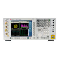
Keysight N9038A Manual (119 pages)
Signal Analyzers, Instrument Messages
Brand:
Keysight
| Category:
Measuring Instruments
| Size: 1 MB
Table of Contents
Signal Analyzers
1
Safety Information
2
Table of Contents
4
List of Instrument Messages
6
Overview of Instrument Messaging System
24
A-Series and B-Series Differences
24
Message Types
24
Event and Condition Categories
26
Event Categories
27
Condition Categories
28
Error Message Fields
29
Event Queues & Displays
30
Message Display & Controls
32
A-Series
32
B-Series
32
Event Message Boxes
32
Status Bar
34
Status Dialog
34
Advisory Messages
36
Band Adjust Has no Effect on a Fixed Marker
37
Fixed lo Freq Should be Greater than RF Stop Freq
38
LO Fixed Freq Should be Greater than if Stop Freq
39
Probe Disconnected, Reverting to Cable Calibration Data; <Port
40
Signals Deleted
41
Event Messages
42
800, Operation Complete Event
43
700, Request Control Event
43
600, User Request Event
43
500, Power on Event
43
To -499, Query Errors
43
Query DEADLOCKED
44
To -399, Device-Specific Errors
45
Calibration Memory Lost
46
Calibration Failed; <Failure Msg><Port
47
Settings Conflict Errors
48
Settings Conflict; <Trigger Source> Trigger Is Not Available While Input Is <Input Port
49
Settings Conflict; Averaged Acquisition Duration Time Exceeds Maximum Value, Acq
50
Settings Conflict; Can't Auto-Couple Res BW in Zero Span
51
Settings Conflict; Db*/Mhz Is Not Applicable to the Following Y-Axis Units, Dbm, W, V, a
52
Settings Conflict; Electronic Attenuator Unavailable with Preamp on
53
Settings Conflict; Feature Not Supported for this Measurement
54
Settings Conflict; Freq > 3.6 Ghz Unavailable While Electronic Attenuator Enabled
55
Settings Conflict; Gate Is Not Available When Marker Count on
56
Settings Conflict; Input Port Is Not Available While Occupied by Output of Incompatible Frequency
57
Settings Conflict; Marker Cannot be Relative to Itself
58
Settings Conflict; MPA GPS Port Power Setting <N>Dbm Is Lower than -130Dbm Minimum
59
Settings Conflict; Normalize Is Not Available While Demod View Is on
60
Settings Conflict; Param Only Available When Frequency Mode Is Swept
61
Settings Conflict; Pre-Trigger Is Insufficient for Demod. Decrease Trig Delay
62
Settings Conflict; Signal Track Is Not Available with Continuous Peak
63
Settings Conflict; Step Keys Are Not Available to Modify this Function
64
Settings Conflict; too Many Points; Stop Freq Clipped to Nearest Value Allowed
65
Settings Conflict;Auto Scan Time/Meas Time Do Not Apply in Stepped Scan Type
66
To -299, Execution Errors
67
All Ranges Are Off. Turn on at Least a Range
68
Execution Error; no Ranges Are Defined. Activate a Range
69
Arm Ignored
70
Arm Deadlock
71
Parameter Error;License Slot <N> Is Locked, Therefore Cannot be Replaced
72
Data out of Range; Clipped to Source Max/Min
73
Data out of Range; Two Entries Already Exist at this X-Axis Value
74
Illegal Parameter Value; Gated lo Is Not Available While Sweep Type Is Set to FFT
75
Data Corrupt or Stale; Measurement Data Is Not Available
76
Hardware Error
77
Antenna Unit Already in Used in Another Range
78
Mass Storage Error; File <Filename> Wrong Type
79
Mass Storage Error; Sharing Violation
80
Corrupt Media
81
Cannot Create Program
82
Incompatible Type
83
To -199, Command Errors
84
Block Data Error
85
No Error
86
Condition Messages
87
To 99, Calibration
87
To 34, Calibration Skipped
87
To 64, Calibration Needed or Failed
88
ADC Alignment Failure
89
To 92, Calibration Needed (Extended)
90
To 95, Calibration Failure (Extended)
91
To 199, Measurement Integrity
92
Input Overload
93
Input Overload;Adc over Range
94
I/O Error
95
Settings Alert; Acquisition Truncated
96
To 299, Signal Integrity
97
Burst Not Found
99
Carrier(S) Incorrect or Missing
100
Demod Error
101
To 399, Uncalibrated Integrity
102
AC Coupled: Accy Unspec'D <10 Mhz
103
User Cal; Cal Invalidated
104
Calibration
105
To 499, Power
106
Full Bypass Enabled, Maximum Safe Input Power Reduced
107
To 599, Frequency
108
To 699, Error Summaries
109
To 799, Operation
110
To 899, Temperature
111
Over Current: Reboot
112
Status Register System & SCPI Status Subsystem
114
Status Register System Overview
115
Documents & Web Sites
118
Advertisement
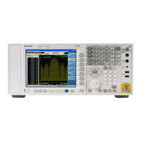
Keysight N9038A Manual (52 pages)
Signal Analyzers
Brand:
Keysight
| Category:
Measuring Instruments
| Size: 0 MB
Table of Contents
Safety Notices
2
Table of Contents
5
Visual Basic
6
1 Introduction to Programming X-Series Applications
9
How to Use this Manual
9
X-Series Programming Options
10
Hardware Connection Formats
11
Interchangeable Virtual Instruments (IVI-COM, IVI-C) Drivers
11
VISA Driver Options
12
Keysight VEE Pro
13
Programming Documentation Roadmap
14
2 SCPI Programming Fundamentals
15
SCPI Language Basics
16
Command Keywords, Separators and Syntax
16
Creating Valid Commands
17
Special Characters in Commands
17
Parameters in Commands
19
Variable Parameters
19
Block Program Data
21
Writing Multiple Commands on the same Line
21
SCPI Termination and Separator Syntax Examples
21
Where to Find X-Series SCPI Command Definitions
23
Help System Features for SCPI Programmers
23
Help System Contents Pane
23
Help Topic Content
24
List of SCPI Commands
25
Simple SCPI Communication Methods
26
Communicating SCPI Using Telnet
26
Determining Instrument IP Address
27
Enabling Telnet in Windows
28
Communicating SCPI Using Keysight Connection Expert
28
Techniques for Improving Measurement Performance
31
Turn off Display Updates
31
Use Binary Data Format Instead of ASCII
31
Minimize the Number of Bus Transactions
31
Use USB or LAN Connection Instead of GPIB
32
Minimize Dut/Instrument Setup Changes
32
Avoid Unnecessary Use of *RST
32
Avoid Automatic Attenuator Setting
32
Avoid Using Rfburst Trigger for Single Burst Signals
32
Making a Single Burst Measurement
33
Optimize GSM Output RF Spectrum Switching Measurement (N9071A Measurement Application)
33
To Make Power Measurements on Multiple Bursts or Slots Use Calculate:data<N>:Compress
33
More Hints & Tips
34
3 Developing and Deploying VISA Projects
35
Programming in Visual Basic 6 with VISA
35
Location of Header Files
35
Programming in C or C++ with VISA
35
Location of Header Files & Libraries
35
Programming with Microsoft .NET and VISA
36
Location of Header Files
36
Requirements for Deploying a VISA Project
37
Multiple VISA DLL Versions
37
4 Program Samples
39
Where to Find Sample Programs
39
N9060A Spectrum Analyzer Mode Programing Samples
40
Matrix of Program Sample Functionality and Programming Language
40
Visual Basic
41
Retrieve Screen Images
42
Read Binary Trace Data
42
C, C
42
Retrieve Screen Image
42
Poll Method for Operation Complete
43
Set and Query Relative Band Power Markers
43
Set Traces and Couple Markers
43
SRQ Interrupt Method for Operation Complete
43
SRQ Method for Operation Complete
43
Phase Noise Trace Math
44
C#.NET & Visual Studio 2010
44
Phase Noise Trace Math Calculation
44
Poll Method for Operation Complete
45
Retrieve Screen Images
45
SRQ Method for Operation Complete
45
Phase Noise Trace Math
46
Keysight VEE Pro
46
Retrieve Screen Images
47
Retrieve Trace Data
47
Labview
47
Screen Capture
47
Matlab
47
46 A
47
IVI-COM Personality (Mode) Select
48
Switch Instrument Mode 42 B 45 C
48
Upload a File
48
Upload a State File
48
N9064A VXA Vector Signal Analyzer Programming Samples
49
Vector Analysis Measurement
49
Digital Demod Measurement
49
Documents & Web Sites
51
Developer Resources
52
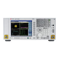
Keysight N9038A Measurement Manual (36 pages)
Signal Analyzer Analog Demod Measurement Application
Brand:
Keysight
| Category:
Measuring Instruments
| Size: 0 MB
Table of Contents
Table of Contents
5
1 Demodulating AM, FM, ΦM, FM Stereo/Rds Signals
7
Setting up and Making a Measurement
8
Making the Initial Signal Connection
8
Using Analyzer Mode and Measurement Presets
8
The 3 Steps to Set up and Make Measurements
9
Demodulating an am Signal
11
Demodulating an FM Signal
12
Demodulating an FM Stereo/Rds Signal
13
Measuring L Only FM Stereo/Rds Signals
13
Measuring L=R FM Stereo/Rds Signals
19
2 Concepts
25
AM Concepts
26
FM Concepts
28
FM Stereo/Rds Concepts
30
FM Stereo
30
Rds/Rbds
30
Demodulating an am Signal Using the Analyzer as a Fixed Tuned Receiver (Time-Domain)
32
Demodulating an FM Signal Using the Analyzer as a Fixed Tuned Receiver (Time-Domain)
33
Demodulating an FM Stereo/Rds Signal Using the Analyzer as a Fixed Tuned Receiver (Time-Domain)
34
Modulation Distortion Measurement Concepts
35
Purpose
35
Measurement Technique
35
Modulation SINAD Measurement Concepts
36
Purpose
36
Measurement Technique
36
Keysight N9038A Installation Note (33 pages)
MXE EMI Receiver, Option HL4, High Performance Digital Signal Processing Upgrade
Brand:
Keysight
| Category:
Receiver
| Size: 1 MB
Table of Contents
Table of Contents
5
ESD Information
6
Protection from Electrostatic Discharge
6
Handling of Electronic Components and ESD
7
Test Equipment Usage and ESD
7
For Additional Information about ESD
7
Installation Instructions
8
Instrument Software Version Verification
8
Instrument Dress Cover Removal
9
Top Brace and Power Supply Bracket Removal
10
Rear Panel Removal
12
Right Outer Chassis Side Removal
13
Front End Control Assembly Removal
14
Enhanced Front End Control Assembly Installation
15
Analog/Digital if Assembly Removal
16
Enhanced Analog If/High Performance Digital if Installation
19
Rear Panel Installation
23
Miscellaneous if Cable Installation
24
Right Outer Chassis Side Installation
25
Top Brace and Power Supply Bracket Installation
26
Instrument Dress Cover Installation
26
New Hardware Driver Installation
27
License Key Retrieval and Installation
30
FPGA Programming
30
Installation Verification
31
Adjustments and Performance Verification
32
Adjustments Required
32
Performance Testing Recommended
32
Keysight N9038A Demo Manual (30 pages)
MXE EMI Receiver Self-Guided Demonstration
Brand:
Keysight
| Category:
Measuring Instruments
| Size: 4 MB
Table of Contents
Table of Contents
2
Introduction
3
Demonstration Preparation
5
Making Measurements
6
Single Frequency Measurement
20
Diagnostic Tools
22
Other Features
25
Appendix
28
Web Resources
29
Keysight N9038A Installation Note (10 pages)
MXE EMI Receiver. Real-Time Spectrum Analysis Upgrade Option RT1
Brand:
Keysight
| Category:
Receiver
| Size: 0 MB
Keysight N9038A Installation Note (8 pages)
MXE EMI Receiver Option YAS Y-Axis Screen Video Out
Brand:
Keysight
| Category:
Receiver
| Size: 0 MB
Table of Contents
Option YAS Installation Kit
3
Installation Procedure over USB
5
Verify the Installation
7
Utilities, Adjustments, and Performance Verification Tests
8
Advertisement
Related Products
Keysight N9030A
Keysight N9030A-503
Keysight N9030A-508
Keysight N9030B-B5
Keysight N9030B PXA
Keysight N9032B PXA
Keysight N9032B
Keysight N9030B-LNP
Keysight N9030B-MPB
Keysight N9030B-B2X
Keysight Categories
Measuring Instruments
Test Equipment
Multimeter
Portable Generator
Power Supply
More Keysight Manuals
Login
Sign In
OR
Sign in with Facebook
Sign in with Google
Upload manual
Upload from disk
Upload from URL