Sign In
Upload
Manuals
Brands
Allied Telesis Manuals
Switch
IS230-10GP
Allied Telesis IS230-10GP Managed Switch Manuals
Manuals and User Guides for Allied Telesis IS230-10GP Managed Switch. We have
4
Allied Telesis IS230-10GP Managed Switch manuals available for free PDF download: Web User Manual, Installation Manual, Reference Manual
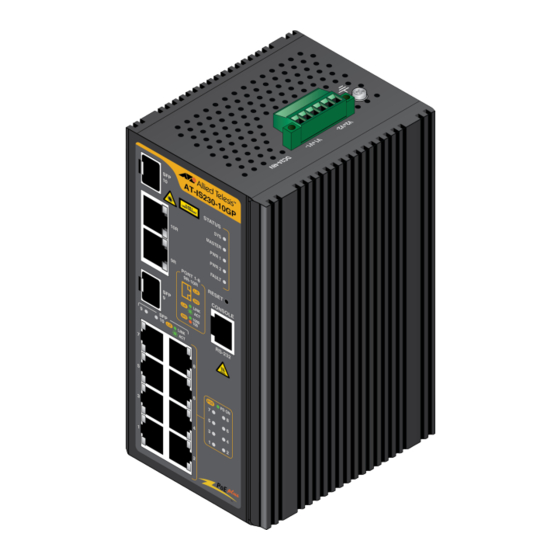
Allied Telesis IS230-10GP Web User Manual (136 pages)
Industrial Ethernet Layer 2 Switch
Brand:
Allied Telesis
| Category:
Network Router
| Size: 6 MB
Table of Contents
Table of Contents
3
Preface
16
Safety Symbols Used in this Document
17
Contacting Allied Telesis
18
Chapter 1: Configuration Utility
20
First Time Setup
21
Overview
21
Introduction
21
Administrative Interface Access
21
Default User Name and Password
22
Using the Graphical (Web) Interface
22
Configuring the Switch for Network Access
23
Configuring the Ethernet Ports
24
Command Line Interface Configuration
25
Introduction to Command-Line Interface (CLI)
25
Accessing the CLI
25
Web Browser Configuration
26
Default Network Configuration
26
Log in
26
Figure 1: Login Screen
26
Change Default Password
27
Figure 2: Initial Web Window - Monitor > Device Information
27
Figure 3: Switch > Tools > User Account - Add/Edit User Window
27
Chapter 2: Managing Switch
30
Monitoring
31
Device Information
31
Figure 4: Monitoring > Device Information
31
Logging Message
32
Figure 5: Monitoring > Logging Message
32
Table 1: Device Information
32
Table 2: Logging Message
32
Port Monitoring
33
Figure 6: Monitoring > Port Monitoring > Port Statistics
33
Port Statistics
33
Figure 7: Monitoring > Port Monitoring > Port Utilization
34
Port Utilization
34
Table 3: Port Statistic
34
Link Aggregation
35
LLDP Statistics
35
Figure 8: Monitoring > LLDP Statistics
35
Table 4: Port Utilization
35
Table 5: LLDP Statistics
35
IGMP Statistics
36
Figure 9: Monitoring > IGMP Statistics
36
Table 6: IGMP Statistics
36
MLD Statistics
37
Figure 10: Monitoring > MLD Statistics
37
Table 7: MLD Statistics
37
System
38
IP Settings
38
Figure 11: System > IP Settings
38
Table 8: IP Settings
38
Ipv6 Settings
39
Figure 12: System > Ipv6 Settings
39
Table 9: Ipv6 Settings
39
DHCP Client Option 82
40
Figure 13: System > DHCP Client Option 82
40
Table 10: DHCP Client Option 82
40
DHCP Auto Provision
41
Management VLAN
41
Figure 14: System > DHCP Auto Provision
41
Figure 15: System > Management VLAN
41
Table 11: DHCP Auto Provision
41
Table 12: Management VLAN
41
System Time
42
Figure 16: System > System Time
42
Table 13: System Time
42
Network Port
43
Figure 17: System > Network Port
43
Table 14: Network Port Settings
44
L2 Switching
45
Port Configuration
45
Figure 18: L2 Switching > Port Configuration
45
Table 15: L2 Switching Port Configuration
45
Port Mirror
46
Figure 19: L2 Switching > Port Mirror
46
Table 16: Port Mirror
46
Link Aggregation
47
Figure 20: L2 Switching > Link Aggregation > Load Balance
47
LAG Management
47
Load Balance
47
Table 17: Load Balance
47
Figure 21: L2 Switching > Link Aggregation > LAG Management
48
LAG Port Settings
48
Table 18: LAG Management
48
Figure 22: L2 Switching > Link Aggregation > LAG Port Settings
49
Figure 23: L2 Switching > Link Aggregation > LACP Priority Settings
49
LACP Priority Settings
49
Table 19: LAG Port Settings
49
Table 20: LACP Priority Settings
49
LACP Port Settings
50
Q Vlan
50
Figure 24: L2 Switching > Link Aggregation > LACP Port Settings
50
Table 21: LACP Port Settings
50
Figure 25: L2 Switching > 802.1Q VLAN > VLAN Management
51
PVID Settings
51
Table 22: VLAN Management
51
VLAN Management
51
Figure 26: L2 Switching > 802.1Q VLAN > PVID Settings
52
Port to VLAN
52
Table 23: PVID Settings
52
Figure 27: L2 Switching > 802.1Q VLAN > Port to VLAN
53
Port-VLAN Mapping
53
Table 24: Port to VLAN
53
Q-In-Q
54
Figure 28: L2 Switching > Q-In-Q > Global Settings
54
Global Settings
54
Table 25: Q-In-Q Global Settings
54
Port Settings
55
Garp
55
Figure 29: L2 Switching > Q-In-Q > Port Settings
55
Table 26: Q-In-Q Port Settings
55
Figure 30: L2 Switching > GARP > GARP Settings
56
GARP Settings
56
GVRP Settings
56
Table 27: GARP Settings
56
Az EEE
57
Figure 31: L2 Switching > GARP > GVRP Settings
57
Figure 32: L2 Switching > 802.3Az EEE
57
Table 28: GVRP Settings
57
Table 29: 802.3Az EEE
57
Multicast
58
Figure 33: L2 Switching > Multicast > Multicast Filtering
58
IGMP Snooping
58
Multicast Filtering
58
Table 30: Multicast Filtering
58
Figure 34: L2 Switching > Multicast > IGMP Snooping > IGMP Settings
59
IGMP Querier
59
IGMP Settings
59
Table 31: IGMP Settings
59
Figure 35: L2 Switching > Multicast > IGMP Snooping > IGMP Querier
60
Figure 36: L2 Switching > Multicast > IGMP Snooping > IGMP Static Groups
60
IGMP Static Groups
60
Table 32: IGMP Querier
60
Table 33: IGMP Static Groups
60
Figure 37: L2 Switching > Multicast > MLD Snooping > MLD Settings
61
MLD Settings
61
MLD Snooping
61
Multicast Groups
61
Router Ports
61
Figure 38: L2 Switching > Multicast > MLD Snooping > MLD Querier
62
MLD Querier
62
Table 34: MLD Settings
62
Table 35: MLD Querier
62
Figure 39: L2 Switching > Multicast > MLD Snooping > MLD Static Groups
63
MLD Static Groups
63
Multicast Groups
63
Router Ports
63
Table 36: MLD Static Group
63
Jumbo Frame
64
Spanning Tree
64
Figure 40: L2 Switching > Jumbo Frame
64
Figure 41: L2 Switching > Spanning Tree > STP Global Settings
64
STP Global Settings
64
Table 37: Jumbo Frame
64
Figure 42: L2 Switching > Spanning Tree > STP Port Settings
65
STP Port Settings
65
Table 38: STP Global Settings
65
Table 39: STP Port Settings
65
Figure 43: L2 Switching > Spanning Tree > STP Bridge Settings
66
STP Bridge Settings
66
Table 40: STP Bridge Settings
66
Figure 44: L2 Switching > Spanning Tree > STP Port Advanced Settings
67
STP Port Advanced Settings
67
Table 41: STP Port Advanced Settings
67
Figure 45: L2 Switching > Spanning Tree > MST Config Identification
68
Figure 46: L2 Switching > Spanning Tree > MST Instance ID Settings
68
MST Config Identification
68
MST Instance ID Settings
68
Table 42: MST Config Identification
68
Figure 47: L2 Switching > Spanning Tree > MST Instance Priority Settings
69
MST Instance Info
69
MST Instance Priority Settings
69
Table 43: MST Instance ID Settings
69
Table 44: MST Instance Priority Settings
69
STP Statistics
70
X-Ring Elite
70
Figure 48: L2 Switching > X-Ring Elite > X-Ring Elite Settings
70
Table 45: X-Ring Elite Settings
70
X-Ring Elite Groups
70
X-Ring Elite Settings
70
X-Ring Pro
71
Figure 49: L2 Switching > X-Ring Elite > X-Ring Elite Groups
71
Figure 50: L2 Switching > X-Ring Pro > X-Ring Pro Settings
71
Table 46: X-Ring Elite Groups
71
X-Ring Pro Settings
71
Figure 51: L2 Switching > X-Ring Pro > X-Ring Pro Groups > X-Ring Pro Groups Settings
72
Table 47: X-Ring Pro Settings
72
Table 48: X-Ring Pro Groups Settings
72
X-Ring Pro Groups
72
X-Ring Pro Groups Settings
72
Chain Settings
73
Couple Settings
73
Figure 52: L2 Switching > X-Ring Pro > X-Ring Pro Groups > Chain Setting
73
Figure 53: L2 Switching > X-Ring Pro > X-Ring Pro Groups > Couple Setting
73
Table 49: Chain Setting
73
Table 50: Couple Setting
73
Pair Settings
74
Loopback Detection
74
Figure 54: L2 Switching > X-Ring Pro > X-Ring Pro Groups > Pair Setting
74
Figure 55: L2 Switching > Loopback Detection > Global Settings
74
Global Settings
74
Table 51: Pair Setting
74
Figure 56: L2 Switching > Loopback Detection > Port Settings
75
Port Settings
75
Table 52: Loopback Detection Global Settings
75
Table 53: Loopback Detection Port Settings
75
MAC Address Table
76
Static MAC
76
Figure 57: MAC Address Table > Static MAC
76
Table 54: Static MAC
76
MAC Aging Time
77
Dynamic Forwarding Table
77
Figure 58: MAC Address Table > MAC Aging Time
77
Figure 59: MAC Address Table > Dynamic Forwarding Table
77
Table 55: MAC Aging Time
77
Table 56: Dynamic Forwarding Table
77
Security
79
Storm Control
79
Figure 60: Security > Storm Control > Global Settings
79
Global Settings
79
Table 57: Storm Control Global Settings
79
Figure 61: Security > Storm Control > Port Settings
80
Port Settings
80
Table 58: Storm Control Port Settings
80
Port Security
81
Protected Ports
81
Figure 62: Security > Port Security
81
Figure 63: Security > Protected Ports
81
Table 59: Port Security
81
Dos Prevention
82
Dos Global Settings
82
Figure 64: Security > Dos Prevention > Dos Global Settings
82
Table 60: Protected Ports
82
Table 61: Dos Global Settings
83
Dos Port Settings
84
Applications
84
Figure 65: Security > Dos Prevention > Dos Port Settings
84
Figure 66: Security > Applications > TELNET
84
Table 62: Dos Port Settings
84
Telnet
84
Figure 67: Security > Applications > SSH
85
Ssh
85
Table 63: TELNET
85
Table 64: SSH
85
Figure 68: Security > Applications > HTTP
86
Figure 69: Security > Applications > HTTPS
86
Http
86
Https
86
Table 65: HTTP
86
802.1X Settings
87
Figure 70: Security > 802.1X > 802.1X Settings
87
Table 66: HTTPS
87
Table 67: 802.1X Settings
87
802.1X Port Configuration
88
Figure 71: Security > 802.1X > 802.1X Port Configuration
88
Table 68: 802.1X Port Configuration
88
IP Security
89
Entry Settings
89
Figure 72: Security > IP Security > Global Settings
89
Figure 73: Security > IP Security > Entry Settings
89
Global Settings
89
Table 69: IP Security Global Settings
89
Table 70: IP Security Entry Settings
90
Qos
91
General
91
Figure 74: Qos > General > Qos Properties
91
Qos Properties
91
Table 71: Qos Properties
91
Figure 75: Qos > General > Qos Settings
92
Qos Scheduling
92
Qos Settings
92
Table 72: Qos Settings
92
Figure 76: Qos > General > Qos Scheduling
93
Table 73: Qos Scheduling
93
Cos Mapping
94
Figure 77: Qos > General > Cos Mapping
94
Table 74: Cos Mapping
94
DSCP Mapping
95
Figure 78: Qos > General > DSCP Mapping
95
Table 75: DSCP Mapping
95
Figure 79: Qos > General > IP Precedence Mapping
96
IP Precedence Mapping
96
Table 76: IP Precedence Mapping
96
Qos Basic Mode
97
Figure 80: Qos > Qos Basic Mode > Global Settings
97
Figure 81: Qos > Qos Basic Mode > Port Settings
97
Global Settings
97
Port Settings
97
Table 77: Qos Basic Mode Global Settings
97
Rate Limit
98
Figure 82: Qos > Rate Limit > Ingress Bandwidth Control
98
Ingress Bandwidth Control
98
Table 78: Qos Basic Mode Port Settings
98
Table 79: Ingress Bandwidth Control
98
Egress Bandwidth Control
99
Egress Queue
99
Figure 83: Qos > Rate Limit > Egress Bandwidth Control
99
Figure 84: Qos > Rate Limit > Egress Queue
99
Table 80: Egress Bandwidth Control
99
Table 81: Egress Queue
100
Management
101
Lldp
101
Figure 85: Management > LLDP > LLDP System Settings
101
LLDP System Settings
101
Table 82: LLDP System Settings
101
Figure 86: Management > LLDP > LLDP Port Settings > LLDP Port Configuration
102
LLDP Port Settings
102
Table 83: LLDP Port Configuration
102
Figure 87: Management > LLDP > LLDP Port Settings > Optional Tlvs Selection
103
Figure 88: Management > LLDP > LLDP Port Settings > VLAN Name TLV VLAN Selection
103
Table 84: Optional Tlvs Selection
103
Figure 89: Management > LLDP > LLDP Local Device Info
104
LLDP Local Device Info
104
Table 85: VLAN Name TLV VLAN Selection
104
LLDP Overloading
105
LLDP Remote Device Info
105
Snmp
105
Figure 90: Management > LLDP > LLDP Remote Device Info
105
SNMP Settings
105
Table 86: LLDP Remote Device Info
105
Figure 91: Management > SNMP > SNMP Settings
106
Figure 92: Management > SNMP > SNMP Community
106
SNMP Community
106
Table 87: SNMP Settings
106
Table 88: SNMP Community
106
Figure 93: Management > SNMP > Snmpv3 Settings
107
Snmpv3 Settings
107
Table 89: SNMP User Settings
107
Figure 94: Management > SNMP > SNMP Trap
108
SNMP Trap
108
Table 90: SNMP Trap
108
Power over Ethernet
109
Figure 95: Management > Power over Ethernet > Poe System Settings
109
Poe System Settings
109
Table 91: Poe System Settings
109
Figure 96: Management > Power over Ethernet > Poe Port Settings
110
Poe Port Settings
110
Table 92: Poe Port Settings
110
Poe Port Status
111
DHCP Server
111
Figure 97: Management > DHCP Server > Status Settings
111
Status Settings
111
Table 93: Status Settings
111
Figure 98: Management > DHCP Server > Global Settings
112
Global Settings
112
Table 94: DHCP Server Global Settings
112
Figure 99: Management > DHCP Server > Port Settings
113
Port Settings
113
Table 95: DHCP Server Port Settings
113
Figure 100: Management > DHCP Server > VLAN Settings
114
Table 96: DHCP Server Port Settings
114
VLAN Settings
114
Figure 101: Management > DHCP Server > Option 82 Settings
115
Option 82 Settings
115
Table 97: Option 82 Settings
115
Figure 102: Management > SMTP Client > Global Settings
116
Global Settings
116
Lease Entry
116
SMTP Client
116
Table 98: SMTP Client Global Settings
116
Figure 103: Management > SMTP Client > Profile Settings
117
Profile Settings
117
Profile Settings Window
117
Table 99: SMTP Client Profile Settings
117
Figure 104: Management > SMTP Client > Profile Settings > Profile Target Mail Settings
118
Figure 105: Management > SMTP Client > Sending Message
118
Profile Target Mail Settings Window
118
Sending Message
118
Table 100: Profile Target Mail Settings
118
Figure 106: Management > RMON > Rmon Statistics
119
Rmon
119
RMON Statistics
119
Table 101: Sending Message
119
Table 102: Rmon Statistics
119
Figure 107: Management > RMON > RMON History
120
RMON History
120
Table 103: RMON History
120
Figure 108: Management > RMON > Rmon Alarm
121
RMON Alarm
121
Table 104: Rmon Alarm
121
Figure 109: Management > RMON > RMON Event
122
RMON Event
122
Table 105: RMON Event
122
Diagnostics
123
Cable Diagnostics
123
Figure 110: Diagnostics > Cable Diagnostics
123
Ping Test
123
Table 106: Cable Diagnostics
123
Figure 111: Diagnostics > Ping Test
124
Table 107: Ping Test
124
Figure 112: Diagnostics > Ipv6 Ping Test
125
Ipv6 Ping Test
125
Table 108: Ipv6 Ping Test
125
Figure 113: Diagnostics > System Log > Logging Service
126
Local Logging
126
Logging Service
126
System Log
126
Table 109: Logging Service
126
Figure 114: Diagnostics > System Log > Local Logging
127
Table 110: Local Logging
127
Figure 115: Diagnostics > System Log > System Log Server
128
System Log Server
128
Table 111: System Log Server
128
DDM
129
Figure 116: Diagnostics > DDM Alarm
129
Figure 117: Diagnostics > DDM Alarm Info
129
Table 112: DDM Alarm
129
Table 113: DDM Alarm Info
129
Figure 118: Diagnostics > LED Indication
130
LED Indication
130
Table 114: DDM Alarm
130
Tools
131
Backup Manager
131
Figure 119: Tools > Backup Manager
131
Table 115: Backup Manager
131
Figure 120: Tools > Upgrade Manager
133
Table 116: Upgrade Manager
133
Upgrade Manager
133
Dual Image
134
Figure 121: Tools > Dual Image
134
Figure 122: Tools > User Account
134
Save Configuration
134
Table 117: Dual Image
134
User Account
134
Reboot Device
135
Reset System
135
Table 118: User Account
135
Troubleshooting
136
Advertisement
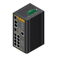
Allied Telesis IS230-10GP Installation Manual (108 pages)
Industrial Ethernet Layer 2 Switches
Brand:
Allied Telesis
| Category:
Switch
| Size: 4 MB
Table of Contents
Electrical Safety and Emissions Standards
3
Safety
4
Emi
4
Ems
4
Shock
5
Freefall
5
Vibration
5
Rohs
5
Table of Contents
7
Preface
13
Safety Symbols Used in this Document
14
Contact Allied Telesis
15
Chapter 1: Overview
17
Hardware Components
18
Figure 1: AT-IS230-10GP Switch Front Panel
18
Figure 2: AT-IS130-6GP Switch Front Panel
18
Figure 3: AT-IS230-10GP Switch Top Panel
19
Figure 4: AT-IS130-6GP Switch Top Panel
19
Figure 5: AT-IS230-10GP Switch Back Panel Features
20
DIN Rail Bracket
21
Figure 6: AT-IS130-6GP Switch Back Panel Features
21
Screw Holes for Wall Brackets
21
Features
22
IS Series Common Features
22
AT-IS230-10GP Managed Features
23
Twisted-Pair Ports
23
Power over Ethernet
24
SFP Slots
24
Console Port
24
Leds
25
Power/Alarm Connector
25
MAC Address Tables
25
AT-IS230-10GP Management Software
25
AT-IS230-10GP Management Methods
25
Installation Options
25
Additional Features
26
10/100/1000Base-T Twisted-Pair Ports
27
Connector Type
27
Speed
27
Duplex Mode
27
Maximum Cable Distance
28
MDI/MDIX
29
Port Pinouts
29
Power over Ethernet
30
Poe Versions
30
Table 1: Maximum Power Levels
30
Powered Device Classes for Poe and Poe
31
Poe Connection Guidelines
31
Table 2: Poe and Poe+ Powered Device Classes
31
Poe Budget
32
Port Prioritization
33
SFP Slots
34
Table 3: Maximum Installation Site Temperatures Versus SFP Temperature Ratings
34
AT-IS230-10GP Console Port
35
AT-IS230-10GP Reset Button
36
Ground Screw
37
Power/Alarm Connector
38
Power Supply Inputs
38
P-Fail Alarm Relay Contacts
38
Figure 7: IS Series Power/Alarm Connectors
38
Figure 8: Example of the P-Fail Alarm Relay Circuit
39
Leds
40
Status Leds
40
Table 4: Status Leds
40
Twisted-Pair Port Leds
41
Figure 9: AT-IS230-10Gptwisted-Pair Port Leds: Ports 1-10
41
Figure 10: AT-IS130-6GP Twisted-Pair Port Leds: Ports 1-5
41
Table 5: Twisted-Pair Port Leds: Ports 1-10
41
SFP Slot Leds
42
Figure 11: AT-IS230-10GP SFP Leds: Ports 9 and 10
42
Figure 12: AT-IS130-6GP SFP LED: Port 6
42
Poe Status Leds
43
Figure 13: AT-IS230-10GP Poe Status Leds: Ports 1-8
43
Figure 14: AT-IS130-6GP Poe Status Leds: Ports 1 - 4
43
Table 6: SFP Slot LED
43
Table 7: Poe Status LED Descriptions
44
Power Supplies
45
At-Is230-10Gp
45
At-Is130-6Gp
45
Power Supply Redundancy
46
Power Supply Connections
46
Chapter 2: Begin Installation
47
Review Safety Precautions
48
Ground Connection
49
Power/Alarm Connection
49
Safety Instructions
49
Safety Statements
52
Safety Precautions with Electricity
55
Review Site Requirements
56
Table 8: Ground Resistivity Recommendations
57
Verify Package Contents
58
Figure 15: Pre-Installed Components on the AT-IS230-10GP Front Panel
58
Figure 16: Pre-Installed Components on the AT-IS130-6GP Front Panel
59
Figure 17: Pre-Installed Components on the Top Panel
60
Figure 18: Pre-Installed DIN Rail Bracket on the Back Panel
60
Figure 19: AT-IS230-10GP Accessory Kit Components
61
Figure 20: AT-IS130-6GP Accessory Kit Components
61
Chapter 3: Install the Switch
63
DIN Rail Installation
64
Figure 21: Orientation of the Switch on a DIN Rail
64
Figure 22: Install Top Slot of DIN Rail Bracket Onto DIN Rail
65
Figure 23: Install Switch on DIN Rail
65
Install Switch on Concrete or Masonry Wall or Industrial Panel
66
Figure 24: Remove Din Rail Mounting Bracket
67
Figure 25: Install Wall Mount Brackets on the Back of the Switch
67
Figure 26: Mark Wall Bracket Hole Locations
68
Figure 27: Install Switch Using Wall Brackets
69
Chapter 4: Install Twisted-Pair Ports Cables
71
Twisted-Pair Port Cables
72
Install SFP Transceivers and Fiber Cables
73
Figure 28: Remove the Dust Plug from an SFP Slot
73
Figure 29: Install SFP Transceiver
74
Figure 30: Remove Dust Cover from SFP Transceiver
74
Figure 31: Connect Fiber Optic Cable to SFP Transceiver
75
Chapter 5: Power on Switch
77
Connect Ground Wire
78
Figure 32: Strip Grounding Wire
78
Figure 33: Loosen Grounding Screw
79
Figure 34: Wrap Grounding Wire Around Ground Screw
79
Figure 35: Secure Grounding Wire to the Switch
79
Power/Alarm Connector Cables
81
Power/Alarm Connector Wiring
81
Figure 36: Strip Power or Alarm Wire
81
Figure 37: Wrap Wire Strands
82
Figure 38: Remove Power/Alarm Connector
82
Figure 39: Loosen Power/Alarm Connector Wire Retaining Screws
83
Figure 40: Insert Power Supply and Alarm Wires into Power/Alarm Connector
83
Figure 41: Verify Wire Installation
84
Figure 42: Tighten Wires in Power/Alarm Connector
84
Figure 43: Insert the Power/Alarm Connector
85
Figure 44: Fasten the Power/Alarm Connector to Chassis
85
Apply Power to Switch
86
Verify Switch Operations
86
Start Management Session
87
Local Management Session
87
Network Management Session
88
Chapter 6: Troubleshooting
91
PWR 1 and PWR 2 Leds
92
Twisted-Pair Ports
93
SFP Slots
94
Power over Ethernet
95
Appendix A: Technical Specifications
97
Physical Specifications
98
Dimensions
98
Weights
98
Cabinet Dimensions
98
Table 9: Product Dimensions
98
Table 10: Product Weights
98
Table 11: Minimum Cabinet Dimensions
98
Environmental Specifications
99
Table 12: Environmental Specifications
99
Power Specifications
100
Table 13: Maximum Power Consumptions
100
Table 14: External Power Supply DC Output Specifications
100
Table 15: Heat Dissipation (British Thermal Units/Hour)
100
Certifications
101
Table 16: Regulatory Approvals
101
Standard Cable Requirements
102
Table 17: Twisted-Pair Standard Cable Requirements
102
Cabling for Poe Devices
103
Table 18: Poe Twisted-Pair Cable Requirements for Powered Devices
103
RJ-45 Twisted-Pair Ethernet Port Pinouts
104
Figure 45: RJ-45 Port Pin Layout (Front View)
104
Table 19: Pin Signals for 10 and 100 Mbps
104
Table 20: Pin Signals for 1000 Mbps
105
RJ-45 Style Serial Console Port Pinouts
106
Table 21: Console Port Pin Signals
106
Power/Alarm Connectors
107
Pin Assignments
107
P-Fail Alarm Contact Rating
107
Figure 46: IS Series Power/Alarm Connectors
107
Table 22: Power Connector Pinout Assignments
107
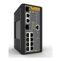
Allied Telesis IS230-10GP Installation Manual (94 pages)
Industrial Ethernet Layer 2 Switch
Brand:
Allied Telesis
| Category:
Network Router
| Size: 4 MB
Table of Contents
Table of Contents
7
Preface
13
Safety Symbols Used in this Document
14
Contact Allied Telesis
15
Chapter 1: Overview
17
Hardware Components
18
Figure 1: Switch Front Panel
18
Figure 2: Switch Top Panel
18
DIN Rail Bracket
19
Figure 3: Switch Back Panel Features
19
Screw Holes for Wall Brackets
19
Features
20
Twisted-Pair Ports
20
Power over Ethernet
21
SFP Slots
21
Console Port
21
Leds
21
Power/Alarm Connector
21
MAC Address Tables
22
Management Software
22
Management Methods
22
Installation Options
22
Additional Features
22
10/100/1000Base-T Twisted-Pair Ports
23
Connector Type
23
Speed
23
Duplex Mode
23
Maximum Distance
24
Cable Requirements
24
Automatic MDIX Detection
24
Port Pinouts
24
Table 1: Twisted-Pair Cable Requirements
24
Power over Ethernet
25
Poe Versions
25
Ethernet Cabling for Poe Devices
25
Table 2: Maximum Power Levels
25
Powered Device Classes for Poe and Poe
26
Table 3: Poe Twisted-Pair Cable Requirements for Powered Devices
26
Table 4: Poe and Poe+ Powered Device Classes
26
Poe Connection Guidelines
27
Poe Budget
27
Port Prioritization
28
SFP Slots
29
Table 5: Maximum Installation Site Temperatures Versus SFP Temperature Ratings
29
Console Port
30
Reset Button
31
Grounding Screw
32
Power/Alarm Connector
33
Power Supplies
33
P-Fail Alarm Relay Contacts
33
Figure 4: Example of the P-Fail Alarm Relay Circuit
34
Leds
35
Status Leds
35
Table 6: Status Leds
35
Twisted-Pair Port Leds
36
Figure 5: Twisted-Pair Port Leds: Ports 1-10
36
Table 7: Twisted-Pair Port Leds: Ports 1-10
36
SFP Slot Leds
37
Poe Status Leds
37
Figure 6: SFP Leds: Ports 9 and 10
37
Figure 7: Poe Status Leds: Ports 1-8
37
Table 8: SFP Slot Leds: Ports 9 and 10
37
Table 9: Poe Status LED Descriptions: Ports 1-8
38
Power Supplies
39
Figure 8: Power/Alarm Connector
40
Chapter 2: Begin Installation
41
Review Safety Precautions
42
Ground Connection
43
Power/Alarm Connection
43
Safety Instructions
43
Figure 9: Power/Alarm Connector on Top of Chassis
43
Safety Precautions with Electricity
47
Review Site Requirements
48
Table 10: Ground Resistivity Recommendations
49
Verify Package Contents
50
Figure 10: Pre-Installed Components on the Front Panel
50
Figure 11: Pre-Installed Components on the Top Panel
51
Figure 12: Pre-Installed DIN Rail Bracket on the Back Panel
51
Figure 13: Components in the Accessory Kit
52
Chapter 3: Install the Switch
53
DIN Rail Installation
54
Figure 14: Orientation of the Switch on a DIN Rail
54
Figure 15: Install Top Slot of DIN Rail Bracket Onto DIN Rail
54
Figure 16: Install Switch on DIN Rail
55
Install Switch on Concrete or Masonry Wall or Industrial Panel
56
Figure 17: Remove Din Rail Mounting Bracket
57
Figure 18: Install Wall Mount Brackets on the Back of the Switch
57
Figure 19: Mark Wall Bracket Hole Locations
58
Figure 20: Install Switch Using Wall Brackets
59
Chapter 4: Install Twisted-Pair Ports Cables
61
Twisted-Pair Port Cables
62
Install SFP Transceivers and Fiber Cables
63
Figure 21: Remove the Dust Plug from an SFP Slot
63
Figure 22: Install SFP Transceiver
64
Figure 23: Remove Dust Cover from SFP Transceiver
64
Figure 24: Connect Fiber Optic Cable to SFP Transceiver
65
Chapter 5: Power on Switch
67
Connect Ground Wire
68
Figure 25: Strip Grounding Wire
68
Figure 26: Loosen Grounding Screw
69
Figure 27: Wrap Grounding Wire Around Ground Screw
69
Figure 28: Secure Grounding Wire to the Switch
69
Power/Alarm Connector Cables
71
Power/Alarm Connector Wiring
71
Figure 29: Strip Power or Alarm Wire
71
Figure 30: Wrap Wire Strands
72
Figure 31: Remove Power/Alarm Connector
72
Figure 32: Loosen Power/Alarm Connector Wire Retaining Screws
73
Figure 33: Insert Power Supply and Alarm Wires into Power/Alarm Connector
73
Figure 34: Verify Wire Installation
73
Figure 35: Tighten Wires in Power/Alarm Connector
74
Figure 36: Insert the Power/Alarm Connector
74
Figure 37: Fasten the Power/Alarm Connector to Chassis
75
Apply Power to Switch
76
Verify Switch Operations
76
Start Local Management Session
77
Chapter 6: Troubleshooting
79
PWR 1 and PWR 2 Leds
80
Twisted-Pair Ports
81
SFP Slots
82
Power over Ethernet
83
Appendix A: Technical Specifications
85
Physical Specifications
86
Table 11: Product Dimensions
86
Table 12: Product Weights
86
Table 13: Minimum Cabinet Dimensions
86
Environmental Specifications
87
Table 14: Environmental Specifications
87
Power Specifications
88
Table 15: Maximum Power Consumptions
88
Table 16: External Power Supply DC Output Specifications
88
Table 17: Heat Dissipation (British Thermal Units/Hour)
88
Certifications
89
Table 18: Regulatory Approvals
89
RJ-45 Twisted-Pair Ethernet Port Pinouts
90
Figure 38: RJ-45 Port Pin Layout (Front View)
90
Table 19: Pin Signals for 10 and 100 Mbps
90
Table 20: Pin Signals for 1000 Mbps
91
RJ-45 Style Serial Console Port Pinouts
92
Table 21: RJ-45 Style Console Port Pin Signals
92
Power/Alarm Connectors
93
Pin Assignments
93
P-Fail Alarm Contact Rating
93
Table 22: Power Connector Pinout Assignments
93
Advertisement
Allied Telesis IS230-10GP Reference Manual (79 pages)
Industrial Ethernet Layer 2 Switch
Brand:
Allied Telesis
| Category:
Switch
| Size: 1 MB
Table of Contents
Table of Contents
3
Preface
7
Safety Symbols Used in this Document
8
Contact Allied Telesis
9
Chapter 1: Command-Line Interface Overview
11
Initially Configuring a Device
11
Accessing the CLI
11
Understanding Command Syntax
12
Understanding Enable and Enable Secret Passwords
12
Abbreviating Commands
12
Using Aliases for CLI Commands
12
Table 1: Default Command Aliases
12
Chapter 2: Layer 2 Features
15
Port Configuration
15
Table 2: Port Configuration
16
Flow Control
18
Port Mirror
18
Table 3: Flow Control
18
Table 4: Port Mirror
18
Link Aggregation
19
Table 5: Link Aggregation
19
802.1Q Vlan
22
Table 6: 802.1Q VLAN
22
MAC Address Table
24
Table 7: MAC Address Table
25
Q-In-Q
27
Table 8: Q-In-Q
27
Garp
28
Gvrp
28
Table 9: GARP
28
Table 10: GVRP
28
802.3Az Energy Efficient Ethernet (EEE)
29
Multicast
30
Table 11: IGMP Snooping
30
MLD Snooping
35
Table 12: MLD Snooping
35
Jumbo Frame
39
Table 13: Jumbo Frame
39
Spanning Tree
40
Table 14: Spanning Tree
40
X-Ring Elite
44
Table 15: X-Ring Elite
44
Loop Detection / Prevention
45
Table 16: Loop Detection / Prevention
45
Chapter 3: Security
47
Storm Control
47
Table 17: Storm Control
47
Port Security
48
Table 18: Port Security
48
802.1X
49
Table 19: 802.1X
49
Account Manager
50
Dos Attack Prevention
50
Table 20: Account Manager
50
Table 21: Dos Attack Prevention
50
IP Security
52
Table 22: IP Security
52
Chapter 4: Quality of Service
53
Qos
53
Table 23: Qos
53
Rate Limit
55
Table 24: Rate Limit
55
Chapter 5: Management
57
IP Management
57
Table 25: IP Management
57
Lldp
59
Table 26: LLDP
59
Snmp
61
Table 27: SNMP
61
Power over Ethernet
62
Table 28: Power over Ethernet
62
Configuration Management
64
Table 29: Configuration Management
64
Firmware Management
65
DHCP Server
65
Table 30: Firmware Management
65
Table 31: DHCP Server
65
DHCP Client Option 82
66
Table 32: DHCP Client
67
System Log (SYSLOG)
68
Table 33: System Log (SYSLOG)
68
SNTP - Network Time Protocol
69
Table 34: SNTP - Simple Network Time Protocol
69
Smtp
70
Table 35: SMTP
70
Rmon
71
Table 36: RMON
71
IP Configuration
72
Telnet
73
Ssh
73
Table 37: IP Configuration
73
Table 38: TELNET
73
Table 39: SSH
73
Http
74
Table 40: HTTP
74
Chapter 6: Diagnostics
75
Cable Diagnostic
75
Table 41: Cable Diagnostic
75
Table 44: Alarm LED
75
Device Monitoring Information
76
IP-Based Diagnostic
76
Table 42: DMI
76
Table 43: IP-Based Diagnostic
76
Alarm Leds
77
System Commands
78
Table 45: System
78
Advertisement
Related Products
Allied Telesis IS Series
Allied Telesis IS130-6GP
Allied Telesis IA Series
Allied Telesis IE340 Series
Allied Telesis IE340-12GP
Allied Telesis IE340L-18GP
Allied Telesis IE200 Series
Allied Telesis IE220 Series
Allied Telesis IE220-6GHX
Allied Telesis IE340-12GT
Allied Telesis Categories
Switch
Network Router
Media Converter
Network Hardware
Wireless Access Point
More Allied Telesis Manuals
Login
Sign In
OR
Sign in with Facebook
Sign in with Google
Upload manual
Upload from disk
Upload from URL