
Subscribe to Our Youtube Channel
Related Manuals for Allied Telesis IS Series


Summary of Contents for Allied Telesis IS Series
- Page 1 IS Series Industrial Ethernet Layer 2 Switch IS230-10GP Installation Guide 613-002547 Rev. A...
- Page 2 Telesis, Inc. be liable for any incidental, special, indirect, or consequential damages whatsoever, including but not limited to lost profits, arising out of or related to this manual or the information contained herein, even if Allied Telesis, Inc. has been advised of, known, or should have known, the possibility of such damages.
- Page 3 European Union Restriction of the Use of Certain Hazardous Substances (RoHS) in Electrical and Electronic Equipment This Allied Telesis RoHS-compliant product conforms to the European Union Restriction of the Use of Certain Hazardous Substances (RoHS) in Electrical and Electronic Equipment. Allied Telesis ensures RoHS conformance by requiring supplier Declarations of Conformity, monitoring incoming materials, and maintaining manufacturing process controls.
- Page 4 IS230-10GP Industrial Ethernet Layer 2 Switch Installation Guide FCC part15 Subpart B/ Class A ICES-003 Class A EN55032 Class A CISPR 32 Class A VCCI Class A AS/NZS CISPR 32 Class A EN61000-6-4 Class A ...
- Page 5 IS230-10GP Industrial Ethernet Layer 2 Switch Installation Guide Translated Safety Statements Important: The indicates that a translation of the safety statement is available in a PDF document titled “Translated Safety Statements” on our web site at http://www.alliedtelesis.com/ support.
-
Page 7: Table Of Contents
Table of Contents Preface ....................................13 Safety Symbols Used in this Document ........................14 Contact Allied Telesis ..............................15 Chapter 1: Overview ................................17 Hardware Components ..............................18 DIN Rail Bracket..............................19 Screw Holes for Wall Brackets ..........................19 Features ..................................20 Twisted-Pair Ports ..............................20 Power Over Ethernet.............................21 SFP Slots ................................21... - Page 8 Contents Chapter 2: Begin Installation ............................41 Review Safety Precautions............................42 Ground Connection .............................. 43 Power/Alarm Connection............................43 Safety Instructions ..............................43 Safety Precautions With Electricity ..........................47 Review Site Requirements ............................48 Verify Package Contents ............................. 50 Chapter 3: Install the Switch............................53 DIN Rail Installation ..............................
- Page 9 Figures Figure 1: Switch Front Panel ..............................18 Figure 2: Switch Top Panel ..............................18 Figure 3: Switch Back Panel Features..........................19 Figure 4: Example of the P-Fail Alarm Relay Circuit ......................34 Figure 5: Twisted-Pair Port LEDs: Ports 1-10........................36 Figure 6: SFP LEDs: Ports 9 and 10 ............................37 Figure 7: PoE Status LEDs: Ports 1-8 ..........................37 Figure 8: Power/Alarm Connector ............................40 Figure 9: Power/Alarm Connector on Top of Chassis ......................43...
- Page 10 Figures...
- Page 11 Tables Table 1: Twisted-Pair Cable Requirements .........................24 Table 2: Maximum Power Levels ............................25 Table 3: PoE Twisted-Pair Cable Requirements for Powered Devices ................26 Table 4: PoE and PoE+ Powered Device Classes ......................26 Table 5: Maximum Installation Site Temperatures Versus SFP Temperature Ratings ............29 Table 6: Status LEDs ................................35 Table 7: Twisted-Pair Port LEDs: Ports 1-10 ........................36 Table 8: SFP Slot LEDs: Ports 9 and 10 ..........................37...
- Page 12 Tables...
-
Page 13: Preface
Preface This guide contains the hardware installation instructions for the IS230-10GP switch. The preface contains the following sections: “Safety Symbols Used in this Document” on page 14 “Contact Allied Telesis” on page 15 ... -
Page 14: Safety Symbols Used In This Document
Preface Safety Symbols Used in this Document This document uses the following conventions. Note Notes provide additional information. Caution Cautions inform you that performing or omitting a specific action may result in equipment damage or loss of data. Warning Warnings inform you that performing or omitting a specific action may result in bodily injury. -
Page 15: Contact Allied Telesis
IS230-10GP Industrial Ethernet Layer 2 Switch Installation Guide Contact Allied Telesis If you need assistance with this product, you may contact Allied Telesis technical support by going to the Support & Services section of the Allied Telesis web site at www.alliedtelesis.com/support. You can find links for... - Page 16 Preface...
-
Page 17: Chapter 1: Overview
Chapter 1 Overview This chapter describes the hardware features of the IS230-10GP switch. The sections in the chapter are listed here: “Hardware Components” on page 18 “Features” on page 20 “10/100/1000Base-T Twisted-Pair Ports” on page 23 “Power over Ethernet” on page 25 ... -
Page 18: Hardware Components
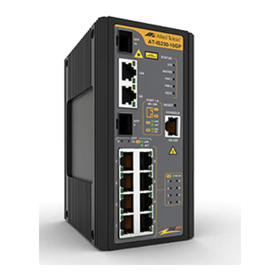
Chapter 1: Overview Hardware Components The front panel of the switch is shown in Figure 1. Fiber System Status 1000Base-T LEDs twisted-pair ports Reset button Console Fiber management port 1000Base-T PoE Status twisted-pair LEDs ports Figure 1. Switch Front Panel Figure 2 shows the components on the switch top panel. -
Page 19: Din Rail Bracket
IS230-10GP Industrial Ethernet Layer 2 Switch Installation Guide Figure 3 identifies the components on the switch back panel. Screw holes for wall bracket DIN rail bracket Screw holes for wall bracket Figure 3. Switch Back Panel Features DIN Rail Bracket The switch comes with one DIN rail bracket pre-installed on the back panel. -
Page 20: Features
Chapter 1: Overview Features The basic features of the IS230-10GP switch are: “Twisted-Pair Ports” “Power Over Ethernet” on page 21 “SFP Slots” on page 21 “Console Port” on page 21 “LEDs” on page 21 “Power/Alarm Connector” on page 21 ... -
Page 21: Power Over Ethernet
IS230-10GP Industrial Ethernet Layer 2 Switch Installation Guide IEEE 802.3az Energy-Efficient Ethernet - LPI at 100BASE-TX support - LPI at 1000BASE-T support Power Over Ports 1 to 8 on the IS230-10GP switch offer the following Power over Ethernet features: Ethernet Ports 1 to 8 support PoE (15 watts) and PoE+ (30 watts) ... -
Page 22: Mac Address Tables
Chapter 1: Overview MAC Address Here are the basic features of the MAC address tables: Tables Storage capacity up to 8,192 MAC address entries Automatic learning and aging 300 second default aging time - range from 10 to 630 seconds ... -
Page 23: 10/100/1000Base-T Twisted-Pair Ports
IS230-10GP Industrial Ethernet Layer 2 Switch Installation Guide 10/100/1000Base-T Twisted-Pair Ports This section describes the following hardware aspects of the twisted-pair ports: “Connector Type” “Speed” “Duplex Mode” “Maximum Distance” “Cable Requirements” on page 24 “Automatic MDIX Detection” on page 24 ... -
Page 24: Maximum Distance
Chapter 1: Overview Maximum The ports have a maximum operating distance of 100 meters (328 feet). Distance Cable The cable requirements for the ports on the IS230-10GP switch are listed in Table 1. Requirements Table 1. Twisted-Pair Cable Requirements Cable Type 10Mbps 100Mbps 1000Mbps... -
Page 25: Power Over Ethernet
IS230-10GP Industrial Ethernet Layer 2 Switch Installation Guide Power over Ethernet Ports 1 to 8 on the IS230-10GP switch switch support Power over Ethernet (PoE). With PoE, the switch can supply electrical power to network devices over the same twisted-pair cables that carry network traffic. The feature can simplify network installation and maintenance because it allows you to use the switch as a central power source for other network devices. -
Page 26: Powered Device Classes For Poe And Poe
Chapter 1: Overview Table 3. PoE Twisted-Pair Cable Requirements for Powered Devices 10Mbps 100Mbps 1000Mbps Cable Type PoE+ PoE+ PoE+ Standard TIA/EIA 568- B-compliant Category 3 shielded or unshielded cabling with 100 ohm impedance and a frequency of 16 MHz. Standard TIA/EIA 568- A-compliant Category 5 shielded or unshielded... -
Page 27: Poe Connection Guidelines
IS230-10GP Industrial Ethernet Layer 2 Switch Installation Guide PoE Connection Here are guidelines for connecting different types of powered devices (PDs) on the PoE switch ports: Guidelines PoE or PoE+ devices that comply with the IEEE 802.3af and 802.3at standards support Alternatives A and can be connected to any of the twisted-pair ports 1 - 8. -
Page 28: Port Prioritization
Chapter 1: Overview Port If the power requirements of the powered devices exceed the switch’s power budget, the switch denies power to some ports based on a system Prioritization called port prioritization. You may use this mechanism to ensure that powered devices critical to the operations of your network are given preferential treatment by the switch in the distribution of power should the demands of the devices exceed the available PoE power capacity. -
Page 29: Sfp Slots
IS230-10GP Industrial Ethernet Layer 2 Switch Installation Guide SFP Slots The two slots support Ethernet 100/1000Base fiber optic, MSA-compliant SFP transceivers. You can use transceivers to connect switches to other network devices over large distances, build a high-speed backbone network between network devices, or connect high-speed devices, such as servers, to your network. -
Page 30: Console Port
Chapter 1: Overview Console Port The Console port is a serial RS-232 port you use to access the management software to configure the features. Management sessions conducted through the Console port are called local management sessions because you have to be at the location of the switch. Local management sessions do not interfere with the network operations of the switch and are not performed over the network. -
Page 31: Reset Button
IS230-10GP Industrial Ethernet Layer 2 Switch Installation Guide Reset Button The Reset button resets the switch. You might reset the switch if it is experiencing a problem. The reset button is recessed in the chassis. To press it, use a straightened paper clip or similar object. The switch behaves as follows: Hold it for 5 sec: The switch software will reboot and return the ... -
Page 32: Grounding Screw
Chapter 1: Overview Grounding Screw The grounding screw is used to connect the chassis to the earth ground at the installation site. The instructions for connecting the post are provided in the paragraph, “Connect Ground Wire” on page 68. Note The switch must be connected to an earth ground. -
Page 33: Power/Alarm Connector
The power supply requirements are described in “Power Supplies” on page 39. Allied Telesis does not sell or provide power supplies for this product. Note This product is intended to be supplied by a UL61010 OR UL61010-2-201 and 60950-1 or 62368-1 Listed DC power source, rated 24-48Vdc, 7A minimum and Tma 75 degree C. -
Page 34: Figure 4: Example Of The P-Fail Alarm Relay Circuit
LED on. When the switch detects that all its ports have links again, it opens the circuit, which turns off the LED. Note External alarm devices are not available from Allied Telesis. Circuit open - LED off Circuit closed - LED on... -
Page 35: Leds
IS230-10GP Industrial Ethernet Layer 2 Switch Installation Guide LEDs The following sections describe the LEDs on the switches: “Status LEDs” on page 35 “Twisted-Pair Port LEDs” on page 36 “SFP Slot LEDs” on page 37 “PoE Status LEDs” on page 37 ... -
Page 36: Twisted-Pair Port Leds
Chapter 1: Overview Twisted-Pair Port Twisted-pair ports 1-10 have two LEDs. The LEDs are identified in Figure 5. LEDs Link/Activity LED (L/A) Speed LED (SPD) Figure 5. Twisted-Pair Port LEDs: Ports 1-10 The descriptions of the twisted-pair port LEDs are defined in Table 7 on page 36. -
Page 37: Sfp Slot Leds
IS230-10GP Industrial Ethernet Layer 2 Switch Installation Guide SFP Slot LEDs Each SFP slot has one LED. The SFP LEDs for Combo ports 9 and 10 are shown in Figure 6. Figure 6. SFP LEDs: Ports 9 and 10 The descriptions of the SFP LEDs are defined in Table 8. Table 8. -
Page 38: Table 9: Poe Status Led Descriptions: Ports 1-8
Chapter 1: Overview The PoE LED functional descriptions for the twisted-pair ports 1 - 8 are defined in Table 9. Table 9. PoE Status LED Descriptions: Ports 1-8 State Description Solid Green PoE is active on the port and is delivering power to a powered device. -
Page 39: Power Supplies
IS230-10GP Industrial Ethernet Layer 2 Switch Installation Guide Power Supplies Allied Telesis does not sell power supplies for these products. Power supplies can be purchased from power supply manufacturers. Note This product is intended to be supplied by a UL61010 OR UL61010-2-201 and 60950-1 or 62368-1 Listed DC power source, rated 24-48Vdc, 7A minimum and Tma 75 degree C. -
Page 40: Figure 8: Power/Alarm Connector
Chapter 1: Overview Note See for “Power Connector Pinout Assignments” on page 93 for the pinout function assignments. Figure 8. Power/Alarm Connector... -
Page 41: Chapter 2: Begin Installation
Chapter 2 Begin Installation The chapter contains the following sections: “Review Safety Precautions” on page 42 “Safety Precautions With Electricity” on page 47 “Review Site Requirements” on page 48 “Verify Package Contents” on page 50 ... -
Page 42: Review Safety Precautions
Chapter 2: Begin Installation Review Safety Precautions Please review the following safety precautions before beginning the installation procedures. Note Safety statements that have the symbol are translated into multiple languages in the Translated Safety Statements document at www.alliedtelesis.com/support. Caution CAUTION: FOR USE IN A CONTROLLED ENVIRONMENT ATTENTION: Pour utilisation dans un environnement contrôlé... -
Page 43: Ground Connection
IS230-10GP Industrial Ethernet Layer 2 Switch Installation Guide Ground Please review this safety information and installation guidelines before installing the ground connection. Refer to “Connect Ground Wire” on Connection page 68 for the installation procedure. Caution Before connecting the power, properly ground the device. Lack of a proper grounding setup may result in a safety risk and could be hazardous. - Page 44 Chapter 2: Begin Installation 5. If the equipment is used in a manner not specified by the manufacturer, the protection provided by the equipment may be impaired. Warning Class 1 Laser product. L1 Warning Do not stare into the laser beam. L2 Warning Do not look directly at the fiber optic ends or inspect the cable ends with an optical lens.
- Page 45 IS230-10GP Industrial Ethernet Layer 2 Switch Installation Guide Caution Air flow around the unit and through the cooling fins must not be restricted. E20 Note All Countries: Install product in accordance with local and National Electrical Codes. E8 Warning Only trained and qualified personnel are allowed to install or replace this equipment.
- Page 46 Note The equipment meets EN61000-4-5 Class 3 on the DC inputs and Ethernet ports. Warning Allied Telesis does not warrant against lightning or power surges causing damage the device. Such damage will be the responsibility of the equipment owner.
-
Page 47: Safety Precautions With Electricity
IS230-10GP Industrial Ethernet Layer 2 Switch Installation Guide Safety Precautions With Electricity Please review the following additional safety guidelines before beginning the installation procedure. Disconnect all power by turning off the circuit breakers before installing or removing the device or when working with the power supplies. -
Page 48: Review Site Requirements
Chapter 2: Begin Installation Review Site Requirements Please observe the following requirements and guidelines when choosing a site for the switch: You can install the switch on a concrete or masonry wall or industrial panel or DIN 35x7.5mm rail. You should not install the switch on a wall or industrial panel that ... -
Page 49: Table 10: Ground Resistivity Recommendations
IS230-10GP Industrial Ethernet Layer 2 Switch Installation Guide The switch and DC power source should be installed close to each other so that the DC power cables are kept as short as possible to minimize voltage loss. The switch and power supply should be properly connected to a ... -
Page 50: Verify Package Contents
Chapter 2: Begin Installation Verify Package Contents Figure 10 identifies the pre-installed components on the front panel of the switch. Eleven dust covers on the twisted- pair ports and Console port Two dust covers on the SFP slots Figure 10. Pre-installed Components on the Front Panel... -
Page 51: Figure 11: Pre-Installed Components On The Top Panel
IS230-10GP Industrial Ethernet Layer 2 Switch Installation Guide The Power/Alarm connector and the grounding screw locations are identified in Figure 11. One M4x8 Phillips-head grounding screw with star washer One 6-pin connector on the DC power PWR 1, PWR 2 and P-Fail connector Figure 11. -
Page 52: Figure 13: Components In The Accessory Kit
Chapter 2: Begin Installation Figure 13 lists the items included in the accessory kit that comes with the switch. Two wall brackets Six M4x8 Phillips-head screws One 2 m (6.6 ft) local management cable with RJ-45 (8P8C) and DB-9 (D-sub 9-pin) connectors Figure 13. -
Page 53: Chapter 3: Install The Switch
Chapter 3 Install the Switch The procedures in this chapter are listed here: “DIN Rail Installation” on page 54 “Install Switch On Concrete or Masonry Wall or Industrial Panel” on page 56... -
Page 54: Din Rail Installation
Chapter 3: Install the Switch DIN Rail Installation The switch comes with a DIN rail bracket pre-installed on the back panel. The bracket is compatible with a DIN 35x7.5mm rail. The bracket has a spring built into it which holds the bracket in place. Figure 14 shows the proper orientation of the switch on a DIN rail. -
Page 55: Figure 16: Install Switch On Din Rail
IS230-10GP Industrial Ethernet Layer 2 Switch Installation Guide 2. Press down (against the spring within the bracket) on the top back edge of the switch until you the bottom edge of the front faceplate of the switch can be pushed back and under the bottom edge of the DIN rail. -
Page 56: Install Switch On Concrete Or Masonry Wall Or Industrial Panel
Chapter 3: Install the Switch Install Switch On Concrete or Masonry Wall or Industrial Panel This section contains instructions on how to install the switch on a concrete or masonry wall or industrial panel. Warning The device is heavy. Always ask for assistance before moving or lifting it to avoid injuring yourself or damaging the equipment. -
Page 57: Figure 17: Remove Din Rail Mounting Bracket
IS230-10GP Industrial Ethernet Layer 2 Switch Installation Guide Figure 17. Remove Din Rail Mounting Bracket 3. On the top and bottom of the switch’s back panel, align and install the two wall mounting brackets (provided) with the six screws (provided). Refer to Figure 18. -
Page 58: Figure 19: Mark Wall Bracket Hole Locations
Chapter 3: Install the Switch 4. Hold the switch on the concrete or masonry wall or industrial panel at the selected location for the device while you use a pencil or pen to mark the locations of the four screw holes in the two wall brackets. Refer to Figure 19. -
Page 59: Figure 20: Install Switch Using Wall Brackets
– Prior to drilling, set the drill to hammer and rotation mode. The modes break up the concrete and clean out the hole. – Allied Telesis recommends cleaning out the holes with a brush or compressed air. b. Insert anchors (not provided) into the four holes. - Page 60 Chapter 3: Install the Switch...
-
Page 61: Chapter 4: Install Twisted-Pair Ports Cables
Chapter 4 Install Twisted-Pair Ports Cables This chapter contains the following procedures: “Twisted-Pair Port Cables” on page 62 “Install SFP Transceivers and Fiber Cables” on page 63 ... -
Page 62: Twisted-Pair Port Cables
Chapter 4: Install Twisted-Pair Ports Cables Twisted-Pair Port Cables Here are the guidelines to cabling the 10/100/1000Base-T twisted-pair ports: The ports have 8-pin RJ45 connectors. The cable specifications for the twisted-pair ports are listed in Table 1 on page 24. The cable specifications for the PoE twisted-pair ports are listed in ... -
Page 63: Install Sfp Transceivers And Fiber Cables
IS230-10GP Industrial Ethernet Layer 2 Switch Installation Guide Install SFP Transceivers and Fiber Cables Please review the following guidelines before installing SFP transceivers: SFP transceivers are hot-swappable. You may install them while the device is powered on. For a list of supported transceivers, refer to the product data sheet. ... -
Page 64: Figure 22: Install Sfp Transceiver
Chapter 4: Install Twisted-Pair Ports Cables 2. Remove the transceiver from its shipping container and store the packaging material in a safe location. 3. Position the transceiver with its handle on the right and slide it into the slot until it clicks into place. Refer to Figure 22. SFP handle Figure 22. -
Page 65: Figure 24: Connect Fiber Optic Cable To Sfp Transceiver
IS230-10GP Industrial Ethernet Layer 2 Switch Installation Guide 5. Connect the fiber optic cable to the transceiver. The connector on the cable should fit snugly into the port, and the tab should lock the connector into place. Refer to Figure 24. This space is reserv Figure 24. - Page 66 Chapter 4: Install Twisted-Pair Ports Cables...
-
Page 67: Chapter 5: Power On Switch
Chapter 5 Power On Switch This chapter contains the following procedures: “Connect Ground Wire” on page 68 “Power/Alarm Connector Cables” on page 71 “Apply Power To Switch” on page 76 “Start Local Management Session” on page 77 ... -
Page 68: Connect Ground Wire
Chapter 5: Power On Switch Connect Ground Wire Here are the guidelines for the ground wire: Warning Take into consideration the following guidelines before wiring the device. Attention Tenez compte des directives suivantes avant de câbler l'appareil. The terminal block (CN1) is suitable for 12-18 AWG (7A). Torque ... -
Page 69: Figure 26: Loosen Grounding Screw
IS230-10GP Industrial Ethernet Layer 2 Switch Installation Guide 2. Loosen the grounding screw several turns with a #2 Phillips-head screwdriver. Refer to Figure 26 on page 69. Figure 26. Loosen Grounding Screw 3. Wrap the grounding wire clockwise around the base of the grounding screw beneath the star-lock washer provided. - Page 70 Chapter 5: Power On Switch 5. Connect the other end of the ground wire to an earth-ground point at the installation site. 6. Go to “Power/Alarm Connector Cables” on page 71.
-
Page 71: Power/Alarm Connector Cables
IS230-10GP Industrial Ethernet Layer 2 Switch Installation Guide Power/Alarm Connector Cables Here are the materials and tools needed to build the DC power and alarm cables: 12-18 AWG stranded wires. 6-wire connector for the power and alarm cables connections. ... -
Page 72: Figure 30: Wrap Wire Strands
Figure 30. Wrap Wire Strands Note Allied Telesis recommends that you also tin the wires with solder as added protection against loose strands. This guide does not provide instructions on how to tin wires. 3. Loosen the two fastening screws on the ends of the Power/Alarm connector . -
Page 73: Figure 32: Loosen Power/Alarm Connector Wire Retaining Screws
IS230-10GP Industrial Ethernet Layer 2 Switch Installation Guide 4. Loosen the wire retaining screws for each of the six wire connections on the power/alarm connector with a #1 screwdriver as shown in Figure 32. Figure 32. Loosen Power/Alarm Connector Wire Retaining Screws 5. -
Page 74: Figure 35: Tighten Wires In Power/Alarm Connector
Chapter 5: Power On Switch 7. Tighten the retaining screws on the power/alarm connector to secure the wires to a torque value 7 lb-in. Refer to Figure 35. Figure 35. Tighten Wires In Power/Alarm Connector 8. Connect the opposite end of the alarm wires to the external alarm circuit. -
Page 75: Figure 37: Fasten The Power/Alarm Connector To Chassis
IS230-10GP Industrial Ethernet Layer 2 Switch Installation Guide 13. Tighten the two connector fastening screws on the ends of the power/ alarm connector to the chassis as shown in Figure 37. This space is reserved fo Figure 37. Fasten the Power/Alarm Connector to Chassis 14. -
Page 76: Apply Power To Switch
Chapter 5: Power On Switch Apply Power To Switch This section contains the procedure for powering on the switch. To power on the chassis, perform the following procedure: 1. Apply power to the DC power supplies. Note The IS230-10GP switch does not have an On/Off switch. To turn the unit OFF, you must turn OFF the power supplies. -
Page 77: Start Local Management Session
IS230-10GP Industrial Ethernet Layer 2 Switch Installation Guide Start Local Management Session This section contains the procedure for starting a local management session on the switch. Please review the following information before performing the procedure: The initial management session with the switch must be a local ... - Page 78 Chapter 5: Power On Switch 4. Press Enter. You are prompted for the name and password of the manager account. 5. Enter the user name and password. The default values are “manager” and “friend” (without the quotes), respectively. Note User names and passwords are case sensitive. The switch starts the local management session and displays the following prompt: awplus>...
-
Page 79: Chapter 6: Troubleshooting
“PWR 1 and PWR 2 LEDs” on page 80 “Twisted-Pair Ports” on page 81 “SFP Slots” on page 82 “Power Over Ethernet” on page 83 Note For further assistance, please contact Allied Telesis Technical Support at www.alliedtelesis.com/support. -
Page 80: Pwr 1 And Pwr 2 Leds
Chapter 6: Troubleshooting PWR 1 and PWR 2 LEDs Problem: A DC power supply is connected to the switch, but the corresponding PWR 1 or PWR 2 LED on the front panel is off. Solutions: The unit is not receiving power from the power supply or the power is outside the operating range of the switch. -
Page 81: Twisted-Pair Ports
IS230-10GP Industrial Ethernet Layer 2 Switch Installation Guide Twisted-Pair Ports Problem: A twisted-pair port on the switch is connected to a network device but the port’s LINK/ACT LED is off. Solutions: The port is unable to establish a link to a network device. Try the following: Verify that the port is connected to the correct twisted-pair cable. -
Page 82: Sfp Slots
Chapter 6: Troubleshooting SFP Slots Problem: The LINK/ACT LED for an SFP transceiver is off. Solutions: The fiber optic port on the transceiver cannot establish a link to a network device. Try the following: Verify that the remote network device connected to the fiber optic ... -
Page 83: Power Over Ethernet
IS230-10GP Industrial Ethernet Layer 2 Switch Installation Guide Power Over Ethernet Problem: The AT-IS230-10GP switch is not providing power to a PoE or PoE+ device. Solutions: Try the following: Check that the device’s power requirements do not exceed those listed in Table 2 on page 25. - Page 84 Chapter 6: Troubleshooting...
-
Page 85: Appendix A: Technical Specifications
Appendix A Technical Specifications This appendix contains the following sections: “Physical Specifications” on page 86 “Environmental Specifications” on page 87 “Power Specifications” on page 88 “Certifications” on page 89 “RJ-45 Twisted-Pair Ethernet Port Pinouts” on page 90 ... -
Page 86: Physical Specifications
Physical Specifications Dimensions Table 11 lists the dimensions of the products. Table 11. Product Dimensions IS230-10GP switch 74 x 105 x 152 mm (W x D x H) (2.91 x 4.13 x 5.98 in.) Weights Table 12 lists the weights of the products. Table 12. -
Page 87: Environmental Specifications
IS230-10GP Industrial Ethernet Layer 2 Switch Installation Guide Environmental Specifications Table 14 lists the environmental specifications of the switches. Table 14. Environmental Specifications Operating Temperature Range -40° C to 75° C (-40° F to 167° F) Storage Temperature -40° C to 85° C (-40° F to 185° F) Operating Humidity 10% to 95% noncondensing Storage Humidity... -
Page 88: Power Specifications
Power Specifications Table 15 lists the maximum power consumption values. Table 15. Maximum Power Consumptions IS230-10GP switch 168W (Max) Table 16 lists the external power supply DC output specifications. Table 16. External Power Supply DC Output Specifications DC Output 24 - 48 VDC, 7.0 A Operating Temperature Range C to 75 C (-40... -
Page 89: Certifications
IS230-10GP Industrial Ethernet Layer 2 Switch Installation Guide Certifications The regulatory approvals of the product are listed in Table 18. Table 18. Regulatory Approvals Safety IEC/EN/UL60950-1 CAN/CSA-C22.2 No.60950-1 UL61010-2-201 CAN/CSA-C22.2 No.61010-2-201 EN 61010-2-201 FCC part15 Subpart B/ Class A ICES-003 Class A EN55032 Class A CISPR 32 Class A VCCI Class A... -
Page 90: Rj-45 Twisted-Pair Ethernet Port Pinouts
RJ-45 Twisted-Pair Ethernet Port Pinouts Figure 38 identifies pin 1 on an RJ-45 twisted-pair port. Figure 38. RJ-45 Port Pin Layout (Front View) Table 19 lists the pin signals for a port when it is operating at 10 or 100 Mbps. -
Page 91: Table 20: Pin Signals For 1000 Mbps
IS230-10GP Industrial Ethernet Layer 2 Switch Installation Guide Table 20 lists the pin signals for a port when it operating at 1000 Mbps. Table 20. Pin Signals for 1000 Mbps Pinout Pair Pair 1 + Pair 1 - Pair 2 + Pair 3 + Pair 3 - Pair 2 -... -
Page 92: Rj-45 Style Serial Console Port Pinouts
RJ-45 Style Serial Console Port Pinouts Table 21 lists the pin signals for the RJ-45 style serial Console port. Table 21. RJ-45 Style Console Port Pin Signals Signal Open Open Transmit Data Ground Ground Receive Data Open Ground... -
Page 93: Power/Alarm Connectors
IS230-10GP Industrial Ethernet Layer 2 Switch Installation Guide Power/Alarm Connectors Pin Assignments The pinout assignments for the power connector are given in Table 22. For power supply requirements, refer to “Power Supplies” on page 39. Table 22. Power Connector Pinout Assignments Assignment Function V1 +...
Need help?
Do you have a question about the IS Series and is the answer not in the manual?
Questions and answers