Table of Contents
Advertisement
Quick Links
Advertisement
Table of Contents

Summary of Contents for SMB MAT-LC-C Series
-
Page 2: Table Of Contents
Contents 1 System Overview…………………………………………………………………………..5 Product Description ........................... 5 1.1.1 Introduction to CPU ......................... 5 1.1.2 C06/C07 Series Expansion Modules ..................6 System Structure ..........................8 Electrical Specifications and Environmental Conditions ..............9 Functional Application ........................10 1.4.1 Motion Control Function ......................10 1.4.2 Logic Control Function ...................... - Page 3 Features of C06/C07 Series Motion Controllers ................48 6 Structure of CODESYS…………………………………………………………………..52 Composition of The Project ......................52 Language ............................54 6.2.1 Instruction List (IL)......................... 54 6.2.2 Structured Text (ST) ......................56 6.2.3 Sequential Function Chart(SFC) ..................61 6.2.4 Functional block diagram(FBD)...
- Page 4 Configurate EtherCAT slave device ..................142 ExtBus library ..........................147 Install ExtBus library files ....................... 147 ExtBus library instruction description..................148 Install the device description file in CODESYS ................155 H.1 Install EtherCAT servo slave device description file .............. 155 Install PLC/402 axis device description file ................
-
Page 5: System Overview
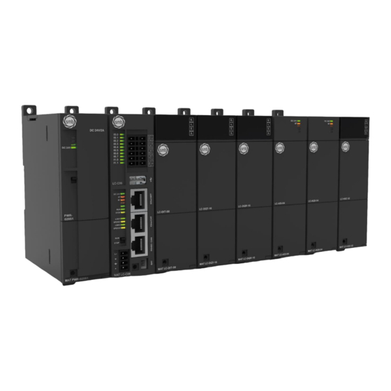
1 System Overview Product Description MAT-LC-CXX series C06/C07motion controllers can be combined with a variety of expansion modules or units to form a powerful programmable logic controller system. It has the characteristics of high speed, high precision, intelligence and ease of use, strong communication and interconnection capabilities, and medium I/O scale. -
Page 6: C06/C07 Series Expansion Modules
◆ Fast Operation The bit instruction execution speed of the CPU is 0.015μs/step. Floating point instruction execution speed is 1µs/step ◆ High-speed Transmission The high-speed bus between CPU and expansion module adopts M-LVDS technology, and the data transmission rate reaches 55Mbps. The CPU integrates 10 digital inputs and supports 6 high-speed counters. - Page 7 Table 1-1 MAT-LC-CXX Series Expansion Modules: Digital Input “Module Digital Output Module MAT-LC-DIT-08 MAT-LC-DQT-08 MAT-LC-DIT-16 MAT-LC-DQT-16 MAT-LC-DQR-08 MAT-LC-DQR-16 Analog Input Module Analog Output Module MAT-LC-AIS-04 MAT-LC-AQS-04 High-speed Pulse Output Power Module Counting Module Module MAT-PWR-020S1 MAT-LC-HSC-02 MAT-LC-HSP-04 EtherCAT Slave Module MAT-LC-ETC-00S1...
-
Page 8: System Structure
System Structure The typical system architecture of C06/C07 application system is shown in the following figure: ➢ C06/C07 can communicate with the host computer through EtherNET communication port (using standard network cable) or RS485 communication port. ➢ The application system can be composed of one central rack and three expansion racks at most, and up to 32 expansion units can be installed. -
Page 9: Electrical Specifications And Environmental Conditions
Electrical Specifications and Environmental Conditions Electromagnetic compatibility (EMC) refers to the ability of electrical equipment to function properly in its electromagnetic environment without interfering with the environment. Table 1-2 and Table 1-3 describe the electrical specification environmental condition standards that the C06/C07 should comply with. -
Page 10: Functional Application
Sinusoidal vibration (bare 5~150Hz, 0.05G2/Hz metal) IEC60068-2 150Hz~500Hz -3dB/oct, 1 hour/axis, X, Y, Z total 3 axes Shock (bare metal) IEC60068-2 15G, 11ms pulse, 3 times/direction High Voltage Insulation Test Between 24V/5V nominal 500 VAC circuits 1500 VAC 110V/220V circuit to ground 1500 VAC 110V/220V circuit to 110V/220V circuit... -
Page 11: Logic Control Function
Scara (select Parallel (parallel Gantry (gantry table) compliance equipped robot) robotic arm) Application-ori ented CNC functions 1.4.2 Logic Control Function Three Program Organization Units Program(Program) Function Block(Function Block) Function(Function) Six programming languages Instruction list(IL) Structured text(ST) ... -
Page 12: Getting Started
2 Getting started Based on a specific example, this chapter introduces how to create a simple project including a PLC program, download the program to the target device LC-C06 motion controller), run and monitor the program. The sample program is written in LD language and includes a program: PLC_PRG. PLC_PRG contains two timers, in which timer 1 starts timing when the program starts, and is set after 5 seconds;... -
Page 13: Start The Codesys Software
First, you need to install the SMB device description configuration file (MAT LC-C06_V1.0.devdesc.xml). After the installation is successful, you can use the SMB device in the program system. The specific operations are as follows: Select the menu item "Tools" → "Device Repository" to open the following dialog box, which... - Page 14 The device is added to the device catalog in the Device Repository. The profiles provided by SMB can be selected by setting the corresponding filters. After the above operations are completed, you can refer to the following steps to enter the device directory to check whether the files are installed correctly: Select the menu item "Tools"...
- Page 15 Expand "PLC" → "SoftMotion PLCs" in the Device Repository dialog box, you can see the SMB device "MAT-LC-C06_V1.0" that has been successfully installed. After checking, if you need to continue to install the device file, please uncheck "Enable Device Repository Dialog" in "Tools"...
- Page 16 2、Create a New Project (1)Select the menu item "File" → "New Project" on the main page of CODESYS, and then select "Standard project" in the pop-up dialog box and set the file name and storage directory). (2)After performing the above operations and confirming, another dialog box will pop up. Select the required file device () and programming language in the dialog box, and then click "OK"...
- Page 17 3、Add Library Users can add instruction library in CODESYS according to their specific needs. The specific operations are as follows: Open the Library Manager in the project tree and select Add Library. In the displayed interface, select the library you want to add and click "OK" to add the required library to the library manager.
-
Page 18: Set Up Communication
Set Up Communication Please refer to the following steps to set up the communication between LC-C06 and the host computer: 1、Set the IP of the programming device to the same network segment as the LC-C06 Before setting the communication, it is necessary to set the IP of the programming device PG/PC to the same network segment as the LC-C06 (IP: 192.168.0.x). -
Page 19: Programming
Programming This example program achieves the purpose: Timer 1 and Timer 2 repeat the set and reset operations in the 5S interval. In the device view, the default POU is "PLC_PRG". Double-click "PLC_PRG" in the device view to automatically open it in the LD language editor in the middle of the CODESYS user interface. The LD language editor includes a declaration part and an implementation part. -
Page 20: Compile And Run The Program
2、Enter the command in the implementation part of PLC_PRG Expand "Ladder Diagram Elements" in the toolbox on the right side of the LD language editor, use the mouse to drag "Power-on Delay Timer TON" to the implementation part of the language editor, and then drag from the "Ladder Diagram Elements"... -
Page 21: Monitoring And Debugging
2、Login, download and start the program Select the menu item "Online" → "Login..." to establish a connection between the application and the LC-C06, and enter the online state. If the communication settings have been made, the following dialog box will pop up: Click "Yes"... - Page 22 3、Use watch window Select the menu item "View" → "Monitor" → "Monitor 1" to open the monitor window. Then, click the first row of the expression column to open the edit box, enter the full path of the variable TRIG1 to be monitored: "Device.Application.PLC_PRG.TRIG1", and then the variable can be written and forced.
-
Page 23: Install
3 Install Installation Precautions The shape of the C06/C07 motion controller makes it extremely easy to install. In the field, the module can be fixed on the back panel of the control cabinet by using the mounting holes, or the module can be fixed on a standard (DIN) rail by using the DIN clip on the device. - Page 24 Figure 3-1 Installation Diagram ❑ Power Budget After selecting the CPU, power supply module, relay module and expansion module of each rack, it is also necessary to confirm whether the current consumption and power consumption of the system bus meet the following conditions: Condition 1: Confirmation of bus current consumption The internal bus voltage is 5VDC, and the current is provided by the CPU .
-
Page 25: Installation Size
When replacing or installing a C06/C07 motion controller, be sure to use the correct or equivalent module. When replacing the C06/C07 motion controller, in addition to using the same module, make sure that the installation direction and position are correct. NOTIFICATION ●... -
Page 26: Installation Method
The rack of the C06/C07 is a mounting rail. You can use this guide rail to install the modules to which the C06/C07 application system belongs. If you are installing modules in a rack, note the following: 1-The number of modules installed on the right side of the CPU does not exceed eight (SM, FM, CP). - Page 27 2) Fix the module on the backplane with suitable screws; 3) If an expansion module is used, connect the flat cable of the expansion module to the expansion port under the bus cover. DIN rail mounting 1) Fix the guide rail on the back panel; 2) Open the DIN clip at the bottom of the module and clamp the back of the module on the DIN rail;...
-
Page 28: Grounding And Wiring
Wiring Wiring Precautions: NOTIFICATION When installing or wiring, be sure to turn off all external power sources. Failure to turn off all power may result in electric shock to the user or damage to the product. After completing the installation or wiring, when starting the power supply or operating the PLC, it should be confirmed whether the terminal block is correctly inserted into the corresponding terminal base of the PLC. -
Page 29: Suppression Circuit
Proper grounding and wiring are essential for all electrical equipment to ensure optimal operating characteristics for your system, as well as provide better protection from electrical noise for your system. The wiring of the C06/C07 motion controller and its related equipment follows all valid electrical coding rules. - Page 30 ❑ AC output and relay output to control AC load The AC output has internal protection for most applications, as the relay can be used for DC or AC loads so no internal protection is provided. Figure 3-7 shows an example of an AC load suppression circuit. In most applications, an additional metal oxide variable resistor (MOV) can limit the peak voltage, thereby protecting the internal circuitry of the C06/C07 motion controller.
-
Page 31: Power Module
4 Power Module 4.1 Specifications PWR-020S1 power supply module, the best match for MAT-LC-CXX series CPU, can provide 24V DC power supply for CPU and expansion modules (except digital modules). Please select a power supply module for each rack, and select other power supply for digital input and output power supply and sensor power supply. -
Page 32: Interface Diagram
Overcurrent Protection Power output provides overcurrent protection Safe Electromagnetic Compatibility Withstand voltage Input~Output: 1.5KVDC, Input-PE: 1.5KVDC, Output-PE: 500VDC Input~Output, Input-PE, Output-PE: 100MΩ/500VDC Isolation resistance According to the standard Safety refer UL60950 UL1950, electromagnetic compatibility refer to EN55022 4.2 Wiring Specifications 4.2.1 Interface diagram 4.2.2... - Page 33 Table 4-5 Definition of 24V DC output power interface of PWR-020S1 4-Position Removable Signal Signal definition Terminal 24Vpower supply positive 24Vpower supply negative 24Vpower supply positive 24Vpower supply negative Table 4-6 DIP switch definition of PWR-020S1 Two-state switch Tag number Dial direction Signal definition With 24V DC output...
-
Page 34: Main Control Module
5 Main Control Module The C06/C07 main control module is the central processing unit of the application system. As the core control device of the system, it is used to process various operations and the operation of user programs. Table 5-1 Basic characteristics of the main control module Name Specifications Order NO. -
Page 35: Cpu Input Function
supply SF indicator (red) On: System failure; Off: No error BF indicator (red) On: bus fault; off: no error RUN indicator (green) On: the system is running; off: the system is stopped STOP indicator (yellow) On: the system is stopped; off: the system is running Network port communication indicator Link1 indicator (green) On: Connected;... - Page 36 Logic 1 signal (minimum) 15 VDC,2.5mA Logic 0 signal (max) 5 VDC,1mA Connecting 2-wire proximity switch sensor 1mA (maximum leakage current allowed) (BERO) Configurable, support 0.2us, 0.4us, 0.8us, 1.6us, 3.2us, 6.4us, input filtering 12.8us, 0.2ms, 0.4ms, 0.8ms, 1.6ms, 3.2ms, 6.4ms, 12.8ms, the default is 6.4ms Isolation (field vs logic) 500V AC, 1 minute...
-
Page 37: High-Speed Count Input
5.2.2 High-speed count input Table 5-4 C06/C07 motion controller high-speed counter input points Model Description Input HSC0 I0.0 I0.1 I0.2 HSC1 I0.3 I0.4 I0.5 HSC2 I0.6 I0.7 HSC3 I1.0 I1.1 HSC4 I0.2 HSC5 I0.5 Single-phase Clock counter with Clock Reset internal direction control Single-phase... - Page 38 13:6.4us 14:12.8us bit0~bit3:HSC Mode(0,1,3,4,6,7,9,10) bit4:Z lock disable 0:enable 1:disable HSC0 MODE BYTE bit5:z dear disable 0:enable 1:disable bit6:reserve bit7:clear lock data 0:clear 1:not clear bit0~bit3:HSC Filter(HZ) HSC0 Filter BYTE 16#2 16#2 1:750K 2:500K 3:375K 4:250K 5:125K 6:100K 7:75K HSC0 Current DINT Value HSC0 Preset...
- Page 39 bit6: Current Value update 0: not update 1: update bit7:HSC Enable 0:disable 1:enable bit0~bit3:HSC Mode(0,1,3,4,6,7,9,10) bit4:Z lock disable 0:enable 1:disable HSC2 MODE BYTE bit5:z dear disable 0:enable 1:disable bit6:reserve bit7:clear lock data 0:clear 1:not clear HSC2 Filter BYTE 16#2 16#2 bit0~bit3:HSC Filter(HZ) 1:750K 2:500K 3:375K 4:250K 5:125K 6:100K 7:75K...
- Page 40 bit5:preset value update, 0:not update 1:update bit6:Current Value update’ 0:not update 1:update bit7:HSC Enable 0:disable 1:enable bit0~bit3:HSC Mode(0,1,3,4,6,7,9,10) bit4:Z lock disable 0:enable 1:disable HSC4 MODE BYTE bit5:z dear disable 0:enable 1:disable bit6:reserve bit7:clear lock data 0:clear 1:not clear bit0~bit3:HSC Filter(HZ) HSC4 Filter BYTE 16#2...
-
Page 41: Communication Function
bit4:direction update, 0:not update 1:update bit5:preset value update, 0:not update 1:update bit6:Current Value update, 0:not update 1:update Communication Function 5.3.1 Communication Port Specification Table 5-6 Integrated Port Specifications Integrated communication functions Bus interface Provide expansion module interface USB port Provides USB host interface EtherNET port Provide 1 EtherNET interface RS485 port... - Page 42 Ethernet network Paramet read write Type Meaning commands TCP_MBUS_MSG enable bit Read and write request bits, each new read and First BOOL write request must be triggered by a pulse Destination IP address, MODBUS over TCP STRING fixed port 502 BYTE Operation command: 0--read, 1--write Select the data type for reading and writing, 0000...
- Page 43 107=Slave rejected the message 108=Slave memory parity error EtherCAT Communication Port Communication 1 EtherCAT communication master interface Interface Baud rate 10/100Mbps adaptive Agreement type EtherCAT interface protocol Maximum cable 100m length per segment Maximum number of Each master supports up to 128 EtherCAT slaves sites Support distributed clock configuration, redundant settings Support startup parameter configuration...
-
Page 44: Schematic Diagram And Definition Of External Interface
5.3.2 Schematic diagram and definition of external interface Schematic diagram of external interface... - Page 45 Table 5-8 Definition of power interface 4-position removable terminals Symbol Signal definition (3.50mm pitch) 24Vpower supply positive 24Vpower supply negative 24Vpower ground Table 5-9 Definition of USB interface USB interface Tag number Symbol Signal definition 红 白 绿 黑 V_Bus Data-Data+ GND V_BUS +5V power supply...
-
Page 46: Make Standard Network Cables
Main control module for CANopen communication The main control module performs CANopen communication with CAN slaves such as SMB Refer to the following diagram to make a standard network cable: Data Memory Specifications C06/C07 series motion controllers store information in different memory units, each unit has a unique address, you can specify the memory address to be accessed, which allows the user program to directly access this information. - Page 47 Table 5-13 Available memory areas: Storage Area Name Size(Bytes) Input fields (physical inputs driven by 1280 inputs, "sensors") Output area (physical outputs driven by 1280 outputs, "actuators") Memory area 32767 Table 5-14 The following length prefixes can be used: Single binary bit None Single binary bit Byte (8 bits)
-
Page 48: Features Of C06/C07 Series Motion Controllers
X1.7 X1.0 X0.15 X0.8 X1.7 X1.0 X1.15 X1.8 D(n-3) D(n/4) W(n-1) W(n/2) Xn.7 Xn.0 X(n/2). X(n/2). n = number of bytes In byte addressing mode, the memory overlap varies, for example: D0 includes B0-B3, W0 includes B0 and B1, W1 includes B1 and B2, and W2 includes B2 and B3. - Page 49 Modbus The SMB_Modbus_V1.1.library file Modbus RTU communication can communication provided by SMB can be used for be carried out through the MODBUS RTU and MODBUS TCP RS485/CAN communication port of communication. For the use of the the C06/C07 motion controller;...
- Page 50 communication connected to the CAN slave station devices through the device catalog: through the RS485/CAN CANBUS, CAN master, CAN slave, communication port and the CAN slave module, etc. standard network cable, and CANopen communication can be realized. <Remarks> Please refer to chapter "7 User Guide" for the usage of various communication methods.
- Page 51 Graphical languages: Sequential Function Chart (SFC), Function Block Diagram (FBD), Ladder Diagram (LD), Continuous Function Chart (CFC) based on Function Block Diagram <Remark> Please refer to chapter "6.2 Language" for the description of programming language. Standardized PLC functions Standardized PLC functions can be realized by using related instructions, such as: type conversion, numerical function, arithmetic function, shift function, Boolean operation function, selection function, comparison function, character string function, timer, counter, edge detection, bistable state elements, etc.
-
Page 52: Structure Of Codesys
6 Structure of CODESYS CODESYS is a device-independent PLC programming system. CODESYS supports not only all programming languages compliant with the IEC 61131-3 standard, but also the C language. Combined with the CODESYS real-time system, multiple controller devices can be configured in one project. - Page 53 variables and returns the result of dividing the product of the first two variables by the third variable. Function block A function block is a POU that provides one or more values in a program. In contrast to functions, a function block has no return value. The declaration of a function block begins with the keyword FUNCTION_BLOCK, and a copy or instance of the function block can be created.
-
Page 54: Language
• PLC browser for controller monitoring. • Tools, related to the target system, call external tool programs inside and outside CODESYS. Library file A series of library files can be included in the project file, and the POUs, data types, and global variables of the library files can be used like custom variables. - Page 55 Operator and Qualifier Meaning LD N make the current value equal to the operand ST N saves the current value at the operand's place Set the Boolean operand to TRUE when the current value is TRUE Set the boolean operand to FALSE when the current value is TRUE AND N,(...
-
Page 56: Structured Text (St)
Here Erg is 7, but if you add a parenthesis: LD 2 MUL (2 ADD 3 ST Erg The result of Erg is 10, and the operation MUL starts to calculate when ")" is reached; at this time, the operand 5 calculates the MUL. 6.2.2 Structured Text (ST) Structured text contains a series of instructions written in a high-level language that can be... - Page 57 Instruction type Example A:=B; CV := CV + 1 ;C:=SIN(X); Assign CMD_TMR(IN := %IX5, PT := 300) ; Call a function block and use the function block A:=CMD_TMR.Q output RETURN ; RETURN D:=B*B ; IF D<0.0 THEN C:=A; ELSIF D=0.0 THEN C:=B;...
- Page 58 Calling function blocks in structured text A function block is called by writing the instance name of the function block and then assigning values to the parameters in parentheses. In the following example, a timer is called by assigning values to two parameters IN and PT, and then the value of the resulting variable Q is assigned to variable A.
- Page 59 2-14 CoDeSys V2.3 <Value2>: <Instruction 2> <Value3, Value4, Value5>: <Instruction 3> <Value6 .. Value10>: <Instruction 4> <Value n>: <Instruction n> ELSE <ELSE instruction> END_CASE; CASE instructions are processed according to the following patterns: If the variable Var1 has the value Value1, then the instruction Instruction1 is executed. If the variable Var1 is not the specified value, then execute the ELSE Instruction.
- Page 60 As long as the counter INT_Var is not greater than END_VALUE, the instruction Instructions will always be executed. Before executing the Instructions, check the value of the counter first. If the INIT_VALUE is greater than the END_VALUE, the Instructions will not be executed. When Instructions are executed, INT_Var is usually increased by a Step size.
-
Page 61: Sequential Function Chart(Sfc
REPEAT Loop The difference between a REPEAT loop and a WHILE loop is that its break condition is checked after the loop executes, which means that the loop executes at least once, regardless of the break condition. Sentence: REPEAT <Instructions> UNTIL <Boolean expression>... - Page 62 An action can consist of a series of instruction lists or structured text instructions, a network of function block diagrams or ladder diagrams, or another sequential function diagram. In simple steps, actions are often linked to steps. To edit an action, double-click on the step or select the step, and then choose the menu command "Extras"...
- Page 63 can be reused many times in a POU. Therefore, they must be associated with a single step with the command "Extras Associate action". In addition to actions, Boolean variables can also be assigned to steps. Active and inactive actions and boolean variables can be controlled using so-called qualifiers. There may be a time delay, and if an action is still active and the next step has already started processing, a concurrent process can be achieved with the qualifier S (set).
- Page 64 Implicit variables can also be accessed by other programs, for example, boolvar1:=sfc1.step1.x; where step1.x is an implicit boolean variable, which represents the state of IEC step step1 in POUsfc1. SFC designator Identifiers are used to control the operation of SFC POUs and are implicitly created during project operation.
-
Page 65: Functional Block Diagram(Fbd
The ExpressionResult structure and implicitly used analysis modules are provided by the AnalysisNew.lib library file, and the analysis modules can also be used explicitly by other POUs not written in SFC. The timeout registration in the previous step is a prerequisite for parsing a conversion expression, so there must be a time watch applied here, and SFCError must be defined in the declaration window. -
Page 66: Ladder Diagram(Ld
6.2.6 Ladder Diagram(LD) Ladder diagram is also a graphics-based programming language, which is close to the structure of electronic circuits. On the one hand, ladder diagram is very suitable for building logic switches. On the other hand, it can also create network diagrams like FBD. Useful when controlling calls to other POUs. -
Page 67: Online Debugging Function
Contact setting/resetting Contacts can be defined as set/reset contacts. A set contact is denoted by an "S" in the contact symbol, it never overrides the TRUE value in the corresponding boolean variable, that is, if the variable is set to TRUE, it will remain in the same state. The reset contact is denoted by "R", it never overwrites the FALSE value in the corresponding boolean variable, and if the variable has been set to FALSE, it will remain in that state. -
Page 68: Standardization
Single cycle If single loop is selected, execution ends when each loop ends. Change value in online mode During operation, variables can be set to a specific value (write value), or redefined to a specific value (force value) after each loop. In online mode, the value of a variable can be changed by double-clicking on its value. -
Page 69: User's Guidance
7 User's Guidance 7.1 Application example of communication method C06/C07 motion controller supports bus, CANopen, EtherCAT, EtherNET and other communication methods. This section will introduce the communication methods supported by LC-C06 through specific examples. 7.1.1 Bus Communication 1、Preparation before communication Table 7-1 Example Components for Bus Communication Components Function... - Page 70 Step 2: Configuration in CODESYS 1) Select "SMB LocalBus" in the device view and right-click to select "Add Device", you can select and add a relay module in the pop-up dialog box, refer to the following...
-
Page 71: Modbus Rtu Communicaiton
CPU executes user program, supplies 5V voltage to bus of Master module: LC-C06 LC-C06 system and communicates with other modules via Ethernet interface. SMB-MAT-HMI serves as Modbus master and communicates SMB-MAT-HMI with LC-C06. Inverter, which supports Modbus protocol, serves as slave of Inverter Modbus RTU and communicates with LC-C06. - Page 72 ◆ LC-C06 serves as slave of Modbus RTU and communicates with SMB-MAT-HMI. 3. Operating steps Step 1: Wiring for LC-C06, power module, HMI and inverter. PWR-020S1 Refer to above diagram for wiring of LC-C06, power module , SMB-MAT-HMI and inverter.
- Page 73 RS485 port of LC-C06 to Modbus port of inverter with communication cable. 3)When LC-C06 serves as slave of Modbus RTU and communicates withSMB-MAT-HMI, connect RS485 port of LC-C06 to Modbus port of SMB-MAT-HMI with communication cable. Step 3: When LC-C06 serves as master of Modbus RTU and communicates with inverter, program LC-C06 as below:...
-
Page 74: Modbus Tcp Communication
7.1.3 Modbus TCP Communication In this chapter, one example will be used to display Modbus TCP communication function of LC-C06 motion controller. 1. Preparation Table 7-3 Example components of Modbus TCP Component Function Programming Install programming device with CODSYS V3.5SP18 Patch6, to device PG\PC configurate, program and debug LC-C06 PLC. - Page 75 2. Network connection Connect two LC-C06, which serve as master and slave of Modbus TCP, with standard network cable and then start Modbus TCP communication: 3. Operating steps Step 1: Wiring between LC-C06 and power module Open front panels of LC-C06 and power module PWR 020S1, wiring according to above network conneciton diagram.
- Page 76 Step 2:Device connection Connect program device and Modbus TCP with standard network cable. Step 3: Program for LC-C06, which serves as slave of Modbus TCP. 1)Input order on shell of PLC, like “setip 192.168.0.1” and push ENTER to set IP address. 2)Program for slave of Modbus TCP in PLC_PRG(PRG).
-
Page 77: Canopen Communication
Executes user program, supplies 5V voltage to bus of LC-C06 LC-C06 motion controller system and communicates with other modules via Ethernet interface. SMB servo driver and In example: SMB servo driver and matching motor are used. motor Standard network cable Connect programming device with LC-C06. Encoder cable Connect servo driver and motor. - Page 78 “CANopen_Manager” to select “Scan device” to display slave device (SMB) under CAN master. 4)Add drive of CAN slave (SMB) If SMB is added as CAN slave in step 3, add its drive here: in devices view, right click CAN slave (SMB) and select “Add SoftMotion CiA 402 Axis” to add the drive.
- Page 79 Input node ID of CAN master in “Overview“ of master: 127 7)CANopen slave(SMB)configuration First, in “Overview” tab, set node ID of slave (address of slave SMB) and then tick “Enable expert settings”. Then, select needed parameters in “PDOs” tab, setting of the example is as below:...
- Page 80 LC-C06 and IPC. Step 5. Run and debug 1) Set the slave address on the front panel of the SMB servo driver: P4:00= 2 ,3 ,4..etc., so that the slave addresses of all CanOpen communication drivers are different.
- Page 81 EtherCAT communication of LC-C06 will be displayed through the example in this chapter. 1. Preparation Table 7-6 Example components of EtherCAT communication Component Function Programming device Install programming device with CODSYS V3.5 SP18 Patch6, to PG\PC configurate, program and debug motion controller LC-C06. Install guide rail To fix modules of the system.
- Page 82 3. Communicaition setup Before communication setting, set IP of programming device PG/PC and LC-C06 (IP: 192.168.0.X) in the same network segment: in local connection property of PC, double click TCP/IP protocol, change “Get IP address automatically” to “Use the following IP address”, then input the IP address “192.168.0.X”.
- Page 83 3)Connect OUT port of first EtherCAT slave to IN port of second EtherCAT slave with standard network cable. Step 2.1 Connect SMB device with cable. Network connection details as below: 1)Connect PC and EtherNET port of LC-C06 with standard network cable;...
- Page 84 Description files provided by SMB can be selected by setting corresponding filters(Note:EtherCAT XML device description profile must be selected). Click "open" button to confirm option, and then add the new device to device directory in the "Device Repository".
- Page 85 After checking, if more device files need to be installed, select “tools”→”Option”, tick “enable Device Repository dialog box”. Hint 1)If you need to use other devices of SMB (CANopen or other EtherCAT slave device), installation of below device description files will be needed: CANopen slave device configuration files(*.eds):SMB_SD_LP_C_V1_XX.eds ...
- Page 86 3) Add EtherCAT master In overview of opened project, right click “Device (MAT-LC-C06_V1.0)”, select “add device” to add EtherCAT master in dialog box: select supplier as <all suppliers>, field bus as “EtherCAT”→”master”→”EtherCAT Master”. 4) Add EtherCAT slave In device view, select EtherCAT master, right click and choose “add device” to add EtherCAT slave in pop up dialog: select supplier as <all suppliers>, field bus as “EtherCAT”→”slave”...
- Page 87 6) EtherCAT slave(ETC-00)configuration In “Overview” tab, tick “enable expert settings”, and set distributed clock as DC “SM-Synchron”. <Remark> Please refer to appendix “F.3 EtherCAT slave device configuration” for more information. Step 5. Refer to “communication setup“ about communication between LC-C06 and IPC. Step 6.
-
Page 88: Electronic Cam Based On Ethercat Communication
Executes user program, supplies 5V voltage to bus and LC-C06 motion controller communicates with other modules via Ethernet interface. SMB servo driver and In the example: SMB servo driver and matching motor are used motor Connect LC-C06 and programming device. Connect LC-C06 and servo driver Standard network cable ... - Page 89 1)Open front panels of LC-C06, power module PWR-020S1 and refer to above diagram for connectiong LC-C06 to PWR-020S1. 2)Connect SMB servo driver to main power and control power supply. Step 2. Connect each device with cable. Network connection details as below:...
- Page 90 EtherCAT slave (SMB) of LC-C06 under EtherCAT master (LC-C06). 3)Add drive of EtherCAT slave In device view, select EtherCAT slave (SMB) and right click to select “Add softmotion- CiA402-axis” in pop dialog to add the drive. 4)EtherCAT master configuration Set source address (MAC) in “Overview”...
- Page 91 <Remark> Please refer to appendix “F.3 EtherCAT slave device configuration” for more information. 6)SMB drive(SM_Driver_GenericDSP402)configuration “Softmotion drive: basic” tab of SM_Driver_GenericDSP402 is as below: Set axis type and limit as “Finite”.
- Page 92 7)Create cam table In device view, open “Device”→”PLC”, right click “Application” and select “Add object”→”cam table”, input table name in pop-up dialog, click “Open” and the cam table is created. Double click the created cam table and set it in ideal conditions as below:...
- Page 93 Step 4. Programming...
-
Page 94: Ethernet/Ip Communication
In device view, double click “PLC_PRG (PRG)” to open program diagram, trigger and download each instruction in sequence. 7.1.6 EtherNET/IP communication You can add any X device that supports Ethernet/IP communication on Codesys and make the necessary adjustments to communicate with the SMB controller and perform the necessary operations. -
Page 95: Application Example Of High Speed Counting Module
Connected with LC-C06 via bus and to count motor speed, counting module position, etc. Servo equipment SMB servo driver Servo motor Connected with SMB servo driver. Standard network cable To connect programming device and CPU, SMB servo driver. Encoder cable To connect SMB servo driver and motor. - Page 96 5)Wiring for high speed counting module and SMB servo driver. Step 2: Run the drive system Set parameters of SMB servo driver to run the motor, refer to <SMB Series AC Servo Driver User Manual> for more detailes. Step 3: PLC communication setup Refer to Chapter 2 Introductory and set communication in CODESYS, to establish communication beteween LC-C06 and programming device.
- Page 97 HSC_SETMODE will not be needed. Step 5: Run the drive system. Set parameters of SMB servo driver to run the motor, refer to <SMB Series AC Servo Driver User Manual> for more detailes. Step 6: Add library file Extbus Library Install library file through “Tools“→“Library“...
-
Page 98: Application Example Of Cpu High Speed Counter
3)Connect SMB servo driver and motor with encoder cable. Step 2: Run the drive system Set parameters of SMB servo driver to run the motor, refer to <SMB Series AC Servo Driver User Manual> for more detailes. Step 3: PLC communication setup Refer to Chapter 2 Introductory and set communication in CODESYS, to establish communication between LC-C06 and programming device. - Page 99 ⚫ In device directory, right click “<blank><blank>” under “CPU Local IO”, select “Insert device” and in pop-up dialog, select supplier as “SMB”, select “Local IO” and click “Insert device” button to add the device, which will be finally displayed under CPU Local IO.
- Page 100 2) Install library file After installation, high speed counter integrated in C06/C07 can be used in program system. Installation steps are as below: In menu, select “Tools”→”Libray Repository” to open below dialog, click “Install”.
- Page 101 Select “SMB_ExtBus_V1.3.library” in dialog, click “Open” button to confirm selection, then in “Device Repository”, add the new device to device directory.
- Page 102 After above operations, refer to below steps to check if the file is correctly installed in device directory: ⚫ In menu, select “Tools“→”Library Repository”→”Misc.” to check installed SMB ExtBus library 3) Program with library file After library file is added correctly, the instructions of the high-speed counter can be called for programming, and HSC_GETCV instruction is the example.
- Page 103 Click the option box, select "SMB_ExtBus"→"HSC" to see instructions related to the high-speed counter, and click needed instruction to confirm and transfer instructions into program.
- Page 104 Select HSC_GETCV instruction. After the instruction is called, the MOD_ID value it inputs is the default one in “Internal configuration”. In device directory, click “Local_IO”, select “Internal configuration“ to see default MDO_ID value. Remark: All MOD_ID value input by HSC related instructions, take default value in “Internal configuration”...
-
Page 105: Hsc Interrupt Example
⚫ In device directory, right click “<blank><blank>” under “CPU Local IO”, select “Insert device” and in pop-up dialog, select supplier as “SMB”, select “Local IO” and click “Insert device” button to add the device, which will be finally displayed under CPU Local IO. - Page 106 2) Install library file After installation, high speed counter integrated in C06/C07 can be used in program system. Installation steps are as below: In menu, select “Tools”→”Libray Repository” to open below dialog, click “Install”.
- Page 107 Select “SMB_ExtBus_V1.3.library” in dialog, click “Open” button to confirm selection, then in “Device Repository”, add the new device to device directory. After above operations, refer to below steps to check if the file is correctly installed in device directory:...
- Page 108 ⚫ In menu, select “Tools“→”Library Repository”→”Misc.” to check installed SMB ExtBus library. 3)Program with library file After library file is added correctly, the instructions of the high-speed counter can be called for programming. 2. Set interrupt Right click “Task configuration”, select “Add object”, then “Tast” to creat a new task.
- Page 109 Click created “Task” to set interrupt. Firstly, set configure type as “External”. Then select external event among the 30 options.
-
Page 110: Cnc Routine
POU. Drag created POU to place under configurated “Task”(interruption task), and write sub-program of interruption. When interruption happens, corresponding sub-program will execute for once. CNC routine Please get CNC function related routine in installation directory of CODESYS: C:\Program Files\SMB\CODESYS\Projects\SoftMotion\Examples\Tutorial... -
Page 111: Appendix
Appendix Table A-1 Explanation of abbreviated terms Abbreviation Full name Explanation Alternating Current Alternating current Direct Current Direct current Analog to Digital Converter Analog to digital converter Digital-to-Analog Converter Digital-to-analog converter Development system under CODESYS Controlled Development System controll Programmable logic Programmable Logic Controller controller Central Processing Unit... -
Page 112: C Specifications Of Extension Modules
Condition 2: Check power consumption of bus When using power module, power consumption of other modules of each frame in total should not exceed max power consumption allowed by power module. When using external power supply, choose model of porper power according to total power consumption of attached modules. - Page 113 Name Specification Order No. PWR-020S1 power Input:85~264V AC MAT-PWR-020S1 module Output:24V DC/2A Table C-2 General properties of PWR-020S1 power module Physical property Dimensions(W×H×D) 34×115×101.6 mm LED Indicator characteristic power indicator On: with 24V DC output, OFF: without 24VDC output (green) Switch property Control 24V DC power output Switch...
- Page 114 Interface diagram Interface definition Table C-4 220V AC input power interface definition of PWR-020S1 3-position removable Signal Signal definiton terminal Live line Neutral wire Earth Table C-5 24V DC output power interface definition of PWR-020S1 4-position removable Signal Signal definition terminal 24VPower supply (positive) 24VPower supply (negative)
-
Page 115: Digital Module
Table C-6 Dial switch definition of PWR-020S1 Two-state switch Position Dial direction Signal definiton Upward With 24V DC output Downward Without 24V DC output Digital module Table C-7 Basic properties of digital module Name Specification Order No. DIT-08 digital module Digital input 8 x 24VDC MAT-LC-DIT-08 DIT-16 digital module... - Page 116 Wiring specification ◆ DIT-08 Wiring diagram ◆ DIT-16 Wiring diagram Digital output module Table C-9 Specification of digital output module Item DQT-08 DQT-16 DQR-08 DQR-16 Dimensions 34×115×100 mm (W×H×D ) Output points Current consumption 50mA 95mA 64mA 130mA 24V DC 70mA 120mA 45mA...
- Page 117 Rated output 24V DC DC:24V,AC: voltage 110V/220V Output voltage 20.4~28.8V DC DC:5~30V, range AC:5~250V Logic 1(Min) 20V DC 0.1V DC,10KΩ load Logic 0(Max) Output current 0.5A (Max) Current at each Max 4A Max 16A common terminal Output leakage current 15uA (maximum) 8A,100ms 5A,4s@10%...
- Page 118 Wiring specification ◆ DQT-08 Wiring diagram ◆ DQT-16 Wiring diagram ◆ DQR-08 Wiring diagram ◆ DQR-16 Wiring diagram...
-
Page 119: Analog Module
Analog module Table C-10 Basic properties of analog module Name Specification Order No. Analog voltage and current input, 4AI x AIS-04 Analog module MAT-LC-AIS-04 12bit Analog voltage and current output, 4AQ x AQS-04 Analog module MAT-LC-AQS-04 12bit Table C-11 General properties of analog module Item AIS-04 AQS-04... - Page 120 Analog input module Item AIS-04 Input type Voltage or current (differential input) Input points Input scale Unipolar: 0~5V,0~10V, bipolar: ±2.5V,±5V Voltage Current 0~20mA,4~20mA Max input voltage 30V DC Max input current 40mA Input impedance ≥2MΩ Voltage 250Ω Current Voltage: 0~+32000 (unipolar), -32000~+32000 (bipolar) Data format Current: 0~+32000 Input step response...
-
Page 121: High Speed Counting Module
Wiring Specification ◆ AIS-04 Wiring diagram High speed counting module Table C-20 Intruduction Name Specifications Part No. 2-ch differential/single-ended signal HSC-02 MAT-LC-HSC-02 input Table C-21 HSC-02 specifications Dimensions W×H×D 34×115×100 mm Power supply Bus supply voltage +5V DC Bus supply current 130mA LED indicator light Indicator light... - Page 122 d input Max input frequency: 500KHz Allowable range of signal duty cycle: 40%-60% Max protection voltage of 30VDC signal input Input filter Configrable,125KHz/250KHz/500KHz/1MHz/2MHz Quadrature encoding 1、2、4 frequency multiplication Counter format 32 Bit Counter reset Yes,Zsignal Counter capture Yes,Zsignal Multi - counter Yes,INTsignal synchronous counting INTsignal voltage...
-
Page 123: Pulse Output Module
Pulse output module Table C-22 Introduction Name Specifications Part No. 4-ch differential/single-ended signal HSP-04 MAT-LC-HSP-04 output Table C-23 HSP-04 specifications Dimensions W×H×D 34×115×101.6 mm Power supply Rated input voltage 24V DC Input voltage range 20.4V~28.8V DC Input current 100mA Reverse polarity protection Bus power voltage... -
Page 124: Ethercat Slave
Wiring diagram EtherCAT slave Table C-29 EtherCATslave introduction Name Specifications Part No. Supports max 8 expansion modules, only EtherCAT slave digital module, analog module and MAT-LC-ETC-00S1 temperature module can be connected Please visit the official website and download the " MAT-LC-CXX Series EtherCAT Slave Module User Manual"... - Page 125 Bus power current 1.6A LED indicator light 24V power light ON:24VDC power supply is normal,OFF:No 24VDC power supply (Green) SF light(Red) ON:EtherCAT slave module failure,OFF:No error BF light(Red) ON: The extension bus is faulty. Off: No error LINK light(Green) ON: Normal;Blinking: pre-operation (2), safe operation (4) (see Note (Slave status indicator) 1);OFF: No connection (0), initialization (1) On: Connects to another EtherCAT interface...
- Page 126 slave is the longest Isolation Isolation of communication interface The EtherCAT communication port uses shielded network cables as communication cables. The available network cables range from 22AWG to 25AWG, and their specifications are as follows. The resistance value is the DC resistance value of a single wire. 24AWG is recommended. Table C-33 Cimmunication cable specifications Outside dia mm Outside dia inch...
-
Page 127: Io Module Channel Configuration
Table C-34 Power interface 4-bit detachable Number Signal Definition terminal 24V power + 24V power - Table C-35 Double RJ45 interface Double RJ45 interface Number Signal Definition Positive end of data transmission Negative end of data transmission Positive end of data reception Negative end of data reception... -
Page 128: Digital Output Module Channel Configuration
3:1.60ms 5:3.20ms 6:6.40ms(default) 7:12.8ms Default value for channel control bytes:16#66 Digital output module channel configuration The configuration parameters of each group (8 channels) are in the following format: Bit 7 Bit 6 Bit 5 Bit 4 Bit 3 Bit 2 Bit 1 Bit 0 Retain... -
Page 129: Analog Output Module Channel Configuration
Analog output module channel configuration Analog output - Group type configuration format: Bit 7 Bit 6 Bit 5 Bit 4 Bit 3 Bit 2 Bit 1 Bit 0 Retain Retain Voltage/C Range(including polarity) urrent Bit 15 Bit 14 Bit 13 Bit 12 Bit 11 Bit 10... -
Page 130: Esmb_Modbus Library
SMB_MODBUS library Install SMB_Modbus library file To enable Modbus communication, install the SMB_MODBUS library file (download the library file from the SMB website: https://www.smbtechnics.com) and run the "Library" instruction to use the library instruction. 1) Install the library Start the CODESYS software, select the menu item "Tools" → "Library Repository" : In the pop-up window, browse to the folder where SMB_modbus. -
Page 131: Modbus_Rtu Library
Expand "Misc" in the above dialog box, select "SMB Modbus Library" in the sub-list and click "Confirm" button to add SMB_MODBUS Library to the current project. Modbus_RTU library 1)Modbus_RTU master MBUS_CTRL Table E-1 MBUS_CTRL instruction Parameter Description Data type Range... - Page 132 1: Instruction is completed Error Error code BYTE 2)Master MBUS_MSG Table E-2 MBUS_MSG instruction Initializ Parameter Description Data type ation Active bit (0: inactive 1: active). If not activated once, First BOOL the instruction is executed once. Slave Slave number BYTE R/W read and write 0:Read...
- Page 133 Table E-3 MBUS_INIT instruction Initializ Parameter Description Data type ation Mode Enable switch (0:OFF 1:ON) BOOL Addr Address BYTE Baud rate Baud DWORD 9600 (1200,2400,4800,9600,19200,38400,57600,115200) Parity check 0: no parity check Parity BYTE 1: indicates odd check 2: parity check Reply delay time (generally set to 0.
-
Page 134: Modbus_Tcp Library
Modbus_TCP library 1)Modbus_Tcp Master MBUS_TCP_REQ Table E-5 MBUS_TCO_REQ instruction Parameter Description Data type Initialization The activation bit (0: inactive 1: active) First activated once and the instruction executed BOOL once. Salve ipaddress,eg.'192.168.0.X' STRING 192.168.0.X Port Slave port number,eg.502 WORD Unit Slave unit number,eg.0 BYTE Read/Write... -
Page 135: F Operation Instructions In Codesys
Table E-10 MBUS_TCP_SLAVE instruction Initializ Parameter Description Data type ation Enable switch Mode 0:OFF BOOL 1:ON Port Salve port number,eg:502 WORD Unit Slave unit number,eg:0 BYTE Reply delay time (generally set to 0. If other communication parameters are correct but Delay communication still fails, increase the value appropriately) - Page 136 2)Add CAN master Select the successfully added CANBUS in the device view and right-click Add Device to add the CAN master station: Fieldbus →CANopen→CANopen Manager →CANopen_Manager in the Add Device dialog box. 3)Add or Scan CAN slave Select the successfully added "CANopen_Manager" in the device view and right-click "Add Device"...
- Page 137 4)Add CANopen slave drive Select the CANopen slave station (SMB_SD_LP_X) in the device view and right click, and select "Add Softmotion - CIA402-Axis" in the pop-up menu, that is, the driver is added successfully. 2、Add EtherCAT communication devices to CODESYS 1)Add EtherCATmaster Right-click "Device(MAT LC-C06)"...
- Page 138 "Add Device", then choose to add EtherCAT slave in the dialog box that pops up: Supplier select "< All suppliers >", fieldbus select "Ethercat" → "slave station" → "AKIMMETAL-SMB SERVO DRIVES" → " SMB_SD_LP_E_V1_XX "; Alternatively, right-click on the EtherCAT master (LC-C06) and select "Scan Device" to display the EtherCAT slave...
-
Page 139: Configurate Canopen Slave Device
Note: EtherCAT slave modules cannot be added by "scanning devices", they can only be added manually. 3)Add EtherCAT slave drive Select the EtherCAT slave station (SMB_SD_LP_X) in the device view and right-click. In the pop-up menu, select "Add Softmotion - CIA402-Axis", that is, the driver has been added successfully. - Page 140 ○ ,1Overview TAB: Set the node ID and select Enable Expert Settings. ② “PDOs”tab In the Receive PDOs (Master => Slave) and Transmit PDOs (Slave => Master) configuration boxes tick the parameter groups that need to be displayed in the Receive PDOs (Master => Slave) Transmit PDOs...
- Page 141 < Remarks > When SMB servo is used as CANopen slave station, please refer to the relevant servo operation manual for the description of each parameter. For example, if SMB_SD_LP_X servo is used as CANopen slave station, please refer to SMB_SD_LP_X Servo Operation Manual.④“Transfer PDOs”tab...
-
Page 142: Configurate Ethercat Slave Device
Configurate EtherCAT slave device After the EtherCAT slave device (SMB_SD_LP_X) has been successfully added to CODESYS, it needs to be configured. Configurate (SMB_SD_LP_X) ① Overview TAB: Select Enable Expert Settings and DC for Synchronization for the distributed clock. ② “Expert Process Data”tab "Expert process data". - Page 143 The input (read) and output (write) parameter sets selected by the device can be used in the I/O mapping dialog as input and output to the PLC (project variables may be mapped). To change the current selection, you must first deselect the current selection by clicking the box in front of it, and then you can set another group.
- Page 144 Configurate ETC-00 ① “DC for synchronization”. ② “Expert Process Data”tab "Expert Process Data" tab: You can add/delete PDO. ③ “Process Data”tab...
- Page 145 Displays the input/output process data of the slave, which is defined by the name, type, and index of the device description file. The input (read) and output (write) parameter sets selected by the device can be used in the I/O mapping dialog as input and output to the PLC (project variables may be mapped).
- Page 146 For modules attached under ETC-00 to read and write parameters, do the following: Debug the Module to which it is attached in the Module I/O Mapping TAB of the ETC-00 slave station (check Always in Bus Cycle Task). Take the Digital Output 16 Bits input Module as an example. Click DQ-16_16DQ (Digital Output 16 Bits) below ETC-00 and select Module I/O mapping so that the parameters can be read and written.
-
Page 147: G Extbus Library
To use the high-speed counter provided by the CPU and the high-speed counter extension module, first install the ExtBus library file (download the library file from the SMB TECHNICS website: (https://www.smbtechnics.com), and then run the "Add Library" instruction to use the library. -
Page 148: Extbus Library Instruction Description
Expand "Miscellaneous" in the above dialog box, select " SMB ExtBus library" in the sublist and click "OK" button to add the ExtBus library to the current project. ExtBu library instruction description The instruction library (ExtBus) supported by the high-speed counter, the description of each... - Page 149 1、Set the counter parameter instruction Function:HSC_300 Parameter Description Type Initialization Remark PLC 16# 0a000605, Module DWOR MOD_ID Module Id of hardware address configuration PLC local value (0-5) Channel CH_ID BYTE HSC module value (0, address CTRL Control byte BYTE 16#F9 See following table Preset DINT...
- Page 150 2. Clear the latched value Function:HSC_CLEARLOCK Parameter Description Type Initialization Remark PLC 16# 0a000605, Module MOD_ID DWORD Module Id of hardware address configuration Channel PLC local value (0-5) CH_ID BYTE address HSC module value (0, 1) Module status byte 0: OK 5: Module parameter Module BYTE...
- Page 151 3. Obtian current count value Function:HSC_GETCV Parameter Descriptio Type Initiali Remark zation Module DWOR PLC 16# 0a000605, Module Id of MOD_ID address hardware configuration PLC local value (0-5) HSC module CH_ID Channel BYTE value (0, 1) Current DINT Current value count value Module status byte 0: OK 2: invalid Module...
- Page 152 5. Obtain current speed by average value 0unction:HSC_GETSPEED-AVG Parameter Description Type Initiali Remark zation Module PLC 16# 0a000605, Module Id of MOD_ID DWORD address hardware configuration Channel PLC local value (0-5) HSC CH_ID BYTE address module value (0, 1) Average Average buffer size is greater BUFSIZE DI1, NT...
- Page 153 Channel PLC local value (0-5) HSC module CH_ID BYTE address value (0, 1) Bit0~Bit3: current mode Bit4: reserved Bit5: HSC0 current count direction Count bit: 1 = count up HSC_STA BYTE status Bit6=1: The current value is equal to the preset value bit Bit7=1: The current value is greater than the preset value bit Module status byte 0: OK 2: invalid...
- Page 154 Bit0~Bit3: HSC counting mode (this machine supports 0, 1, 3, 4, 6, 7, 9, 10; HSC-02 supports 0-11 mode) Mode 0~2: Single-phase counter with internal direction control. Modes 3~5: Single-phase counter with external direction. Modes 6~8: Two-phase counter with 2 clock MODE Count mode BYTE...
-
Page 155: H Install The Device Description File In Codesys
H Install the device description file in CODESYS Install EtherCAT servo slave device description file 1. Open the CODESYS software, select the menu "Tools" → "Device Repository" to open the following dialog box, and click "Install" in the dialog box. 2. -
Page 156: Install Canopenslave Eds File
2. After the above operation, a dialog box will pop up as follows. Please select the file type "Device Description Configuration file (*.devdesc.xml)". Select MAT LC-C06_V1.0.devdesc.xml or MAT LC-C07_V1.0.devdesc.xml and click Open. The installation is successful. Install CANopenslave EDS file 1. - Page 157 2. A dialog box is displayed as follows. Select the file type EDS and DCF file (*.eds.*.DCF) and the suffix SMB_SD_LP_C_V1_XX.eds Click "Open" to install the EDS file successfully.
-
Page 158: I Instruction Quick Check
Instruction Quick Check Operator summary in CODESYS The following table summarizes the operators that exist in the Standard.lib and Util.lib libraries of CODESYS, respectively. Note the 'IL' column: only lines that use this symbol are displayed. A necessary condition is that the first set of necessary operands has been successfully loaded on the previous line (e.g., LD in) The 'Mod.IL' column shows modifiers that are possible in IL: Modifier for the result of the preceding expression being TRUE. - Page 159 Now execute the set operation Bit AND Bit OR bit specific OR bit NOT addition subtraction multiplication division > Greater than >= great than or equal to equal to <> unequal to <= Less than or equal to < Less than MOD(in) Module division INDEXOF(in)
-
Page 160: Standard.lib Library
(in) another basic type. TIME_TO_<type> TIME operand type is converted to another TIME_TO_<type> (in) basic type. TOD_TO_<type>(i TOD operand type is converted to another TOD_TO__<type> basic type. DATE operand type is converted to DATE_TO_<type>( DATE_TO_<type> another basic type. DT operand type is converted to another DT_TO_<type>... -
Page 161: Util.lib Library
Bistable FB is set to dominant. Bistable FB reset. SEMA SEMA FB: Arm board software (interruptible) R_TRIG R_TRIG FB: The rising boundary is monitored. F_TRIG F_TRIG FB: The falling boundary is monitored. FB: Appreciation count. FB:Depreciation count. CTUD CTUD FB:Count up and down. FB:trigger FB:On-Delay lock FB:Off-Delay clock... -
Page 162: Softmotion Library
SoftMotion library SM3_Basic Library This library is the base library for CODESYS SoftMotion applications, so it must be included in the SoftMotion project. This will happen automatically when a SoftMotion device is plugged in. The library provides the following function blocks and functions: ●... - Page 163 SMC_CONTROLLER_MODE It describes which quantity of the motor is controlled. It includes all possible error numbers returned by the SMC_ERROR SoftMotion function block. It defines the homing sequence when used by SMC_HOMING_MODE SMC_Homing. SMC_INT_STATUS It describes the state of the interpolator instance. It is used in the function SMC_ErrorString to determine the SMC_LANGUAGE_TYPE language.
- Page 164 It can be used to check if the actual setpoint of the drive exceeds the maximum value configured in the controller. The SMC_CheckLimits result of the check will be indicated by the bLimitsExceeded output. It will write the position set point to the axis without any SMC_FollowPosition checks.
- Page 165 device, which is connected to a master device in absolute mode, and the master device moves at the specified maximum speed and acceleration/deceleration. It represents a tappet control unit. It acts on the SMC_CAMRegister MC_CAM_REF structure like MC_CamIn, cancels the original track information and only reads the tappet information.
- Page 166 It is used to command a never-ending controlled movement at MC_MoveVelocity a specific speed. MC_PositionProfile It is used to command a time-position locked motion profile. MC_Power It is used to control the power stage ("on" or "off"). MC_ReadActualPosition It will return the actual position of the reference axis. It is used to describe common axis errors not related to MC_ReadAxisError function blocks.
- Page 167 SM3_CNC Library SM3_CNC.Library library are used (according to DIN 66025) to decode trajectories created in the CNC editor. Decoding is to transform the trajectory into a structure so that it can be used by IEC programs (trajectory preprocessing), or can be modified, interpolated, and transformed so that it is readable by the driving device (for example, SMC_NCDecoder, ToolCorr, SMC_AvoidLoop, SMC_SmoothPath, SMC_RoundPath, SMC_Interpolator).
- Page 168 Its value indicates the actual state of the FB instance. possible SMC_INT_STATUS states: SMC_INT_VELMODE Its value determines the velocity profile. It is a member of SMC_GEOINFO, which specifies the geometry SMC_MOVTYP of the object. SMC_TC_STATUS Its value represents the actual state of the FB instance. SMC_TOOLCORRMOD Its value represents the mode in which the SMC_Toolcorr runs.
- Page 169 poqDataIn will be rotated around the Z axis by the given angle dPhi[°]. A positive angle is a mathematical positive rotation (counterclockwise). When it executes, the trajectory contained in poqDataIn will SMC_SCALEQUEUE3D be stretched by the factor fScaleFactor. The path stored in poqDataIn through its execution will be SMC_TRANSLATEQUEUE3D converted according to vec , which is the data type of SMC_VECTOR3D.
- Page 170 It sets the variables of the SMC_OUTQUEUE data structure SMC_OUTQUEUEINIT to its default. This function block restores an interpolated or processed SMC_RESTOREQUEUE structure. This is only possible if the entire trajectory can be stored into the table referenced by poq. SMC_SETQUEUECAPACITY for setting the SMC_OUTQUEUE data structure.
- Page 171 intercepted by the intersection of the two lines. The SMC_SmoothPath function block can be used for trajectory preprocessing. It rounds the path angles, resulting SMC_SMOOTHPATH in a slur path. It is used when the accuracy of the trajectory is not high, but the speed is high, and the speed is not allowed to drop to 0.
- Page 172 This transition module is used to provide reverse SMC_TRAFO_GANTRYH2 transitions to address H gantry systems with fixed drives. The function module is used to operate a three-dimensional gantry operating system without motion. Therefore, this module only adds an offset to each of the X SMC_TRAFOF_GANTRY2 and Y axes.
- Page 173 the trajectory velocity and trajectory direction as the control variable of the axis. ● Inside the SM_Trafo_POUs\Parallel Systems folder Instruction Name Function The conversion module is used to provide a backward SMC_TRAFO_BIPOD_ARM conversion to handle the bipod arm. The conversion module is used to provide backward SMC_TRAFO_TRIPOD conversion for handling tripods.
-
Page 174: J Ordering Information
Ordering Information Table J-1 List of ordering information Specification description Part Number LC-C06 Motion Controller LC-C06 main control module , 32MB program data space, 64KB power-down retention data , 55M expansion bus, 1 RS485 communication port, MODBUS free port protocol , 1 EtherCAT MAT-LC-C06 interface, 1 EtherNET interface, 1 CAN port, 1 USB ports, support SoftMotion...
Need help?
Do you have a question about the MAT-LC-C Series and is the answer not in the manual?
Questions and answers