Table of Contents
Advertisement
AC Servo Drives
V
-
Series
USER'S MANUAL
For Use with Large-Capacity Models
Design and Maintenance
Multi-Winding Drive Unit
Rotational Motor
Analog Voltage and Pulse Train References
Multi-Winding Drive Unit Model: JUSP-MDD01A
SERVOPACK Model: SGDV-J
Converter Model: SGDV-COA
Servomotor Model: SGMVV
MANUAL NO. SIEP S800001 68B
Outline
Panel Operator
Wiring and Connection
Trial Operation
Operation
Adjustments
Utility Functions (Fn)
Monitor Displays (Un)
Troubleshooting
Appendix
1
2
3
4
5
6
7
8
9
10
Advertisement
Table of Contents
Troubleshooting

Related Manuals for YASKAWA JUSP-MD D01A Series


Summary of Contents for YASKAWA JUSP-MD D01A Series
- Page 1 AC Servo Drives Series USER'S MANUAL For Use with Large-Capacity Models Design and Maintenance Multi-Winding Drive Unit Rotational Motor Analog Voltage and Pulse Train References Multi-Winding Drive Unit Model: JUSP-MDD01A SERVOPACK Model: SGDV-J Converter Model: SGDV-COA Servomotor Model: SGMVV Outline Panel Operator Wiring and Connection...
- Page 2 Yaskawa. No patent liability is assumed with respect to the use of the information contained herein. Moreover, because Yaskawa is con- stantly striving to improve its high-quality products, the information contained in this manual is subject to change without notice.
-
Page 3: About This Manual
About this Manual This manual describes information required for designing, testing, adjusting, and maintaining large-capacity models of servo systems in the Σ-V series. Keep this manual in a location where it can be accessed for reference whenever required. Manuals outlined on the following page must also be used as required by the application. - Page 4 Notation Used in this Manual • Notation for Reverse Signals The names of reverse signals (i.e., ones that are valid when low) are written with a forward slash (/) before the signal name. Notation Example BK = /BK • Notation for Parameters The notation depends on whether the parameter requires a value setting (parameter for numeric settings) or requires the selection of a function (parameter for selecting functions).
- Page 5 Manuals Related to the Σ-V Large-Capacity Models Refer to the following manuals as required. Selecting Trial Maintenance Models and Ratings and System Panels and Trial Operation Name Peripheral Specifications Design Wiring Operation and Servo Inspection Devices Adjustment Σ-V Series User’s Manual For Use with Large-Capacity Models Setup...
- Page 6 Trademarks MECHATROLINK is a trademark of the MECHATROLINK Members Association. Safety Information The following conventions are used to indicate precautions in this manual. Failure to heed precautions pro- vided in this manual can result in serious or possibly even fatal injury or damage to the products or to related equipment and systems.
-
Page 7: Safety Precautions
Safety Precautions These safety precautions are very important. Read them before performing any procedures such as checking products on delivery, storage and transportation, installation, wiring, operation and inspection, or disposal. Be sure to always observe these precautions thoroughly. WARNING • Never touch any rotating motor parts while the motor is running. Failure to observe this warning may result in injury. - Page 8 WARNING • Be sure to connect the servomotor’s built-in thermostat to the host controller or to the main circuit magnetic contactor’s operation circuit. Failure to observe this warning may result in injury, fire, or damage to the product. • Usage Example 1: In this example, the output signal from the thermostat is received by the host controller if the thermostat is activated and the host controller turns OFF the servo.
- Page 9 Storage and Transportation CAUTION • Do not store or install the product in the following locations. Failure to observe this caution may result in fire, electric shock, or damage to the product. • Locations subject to direct sunlight • Locations subject to temperatures outside the range specified in the storage/installation temperature con- ditions •...
- Page 10 Wiring CAUTION • Be sure to wire correctly and securely. Failure to observe this caution may result in motor overrun, injury, or malfunction. • Do not connect a commercial power supply to the U, V, or W terminals for the servomotor connec- tion.
- Page 11 Operation CAUTION • Always use the servomotor, multi-winding drive unit, SERVOPACK, and converter in one of the specified combinations. Failure to observe this caution may result in fire or malfunction. • Conduct trial operations on the servomotor alone, with the motor shaft disconnected from the machine to avoid accidents.
- Page 12 • The drawings presented in this manual are typical examples and may not match the product you received. • If the manual must be ordered due to loss or damage, inform your nearest Yaskawa representative or one of the offices listed on the back of this manual.
-
Page 13: Warranty
6. Events for which Yaskawa is not responsible, such as natural or human-made disasters (2) Limitations of Liability 1. Yaskawa shall in no event be responsible for any damage or loss of opportunity to the customer that arises due to failure of the delivered product. - Page 14 2. The customer must confirm that the Yaskawa product is suitable for the systems, machines, and equipment used by the customer. 3. Consult with Yaskawa to determine whether use in the following applications is acceptable. If use in the application is acceptable, use the product with extra allowance in ratings and specifications, and provide safety measures to minimize hazards in the event of failure.
-
Page 15: Harmonized Standards
Harmonized Standards North American Safety Standards (UL) Name (Model) UL Standards (UL File No.) Mark SERVOPACKs (SGDV-J), UL508C (E147823) converters (SGDV-COA) Multi-winding drive units (JUSP-MDD) UL508C (E147823) Servomotors (SGMVV) UL1004 (E165827) European Directives Name (Model) European Directives Harmonized Standards Machinery Directive EN ISO13849-1: 2008, 2006/42/EC... - Page 16 Safe Performance Items Standards Performance Level IEC 61508 SIL2 Safety Integrity Level IEC 62061 SILCL2 IEC 61508, PFH ≤ 1.7×10 [1/h] Probability of Dangerous Failure per Hour IEC 62061 (0.17% of SIL2) Category EN 954-1 Category 3 Performance Level EN ISO 13849-1 PL d (Category 3) Mean Time to Dangerous Failure of Each...
-
Page 17: Table Of Contents
Contents About this Manual ............iii Safety Precautions. - Page 18 3.3 I/O Signal Connections......... 3-15 3.3.1 Names and Functions for Multi-Winding Drive Unit I/O Signals (CN1) .
- Page 19 5.3 Speed Control ..........5-19 5.3.1 Basic Settings for Speed Control .
- Page 20 Chapter 6 Adjustments ........6-1 6.1 Type of Adjustments and Basic Adjustment Procedure .
- Page 21 Chapter 8 Monitor Displays (Un) ......8-1 8.1 List of Monitor Displays ......... 8-2 8.2 Viewing Monitor Displays.
- Page 22 Outline 1.1 Σ-V Large-Capacity Multi-Winding Drive Unit, SERVOPACKs and Converters ..........1-2 1.2 System Configuration Diagram .
-
Page 23: Σ-V Large-Capacity Multi-Winding Drive Unit, Servopacks
1 Outline Σ-V Large-Capacity Multi-Winding Drive Unit, SERVOPACKs and Converters The Σ-V-series servo drives were designed for applications that require high-speed, high-frequency position- ing. They can quickly maximize machine performance to help improve productivity. System Configuration Diagram A multi-winding drive system consists of a multi-winding drive unit, SERVOPACKs, converters, and a multi-winding servomotor. -
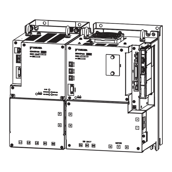
Page 24: Part Names
1.3 Part Names Part Names 1.3.1 Multi-Winding Drive Unit Part Names The part names of the multi-winding drive unit are given below. Name Description Reference Control power supply input CN7A is the 24 VDC (±15%) input connector. connectors (CN7A and CN7B takes the same input, but it is normally not –... -
Page 25: Servopack Part Names
1 Outline 1.3.2 SERVOPACK Part Names (cont’d) Name Description Reference Rotary switch (S1001) Do not use this switch. – DIP switch (S1002) Do not use this switch. – MS1 LED indicator This indicator cannot be used. – MMA, MM2, MM3, and MM4 Lights green when local communications are –... - Page 26 1.3 Part Names (cont’d) Name Description Reference Indicates the servo status with a seven-segment Panel display – LED display. Indicates the SERVOPACK model and ratings. Nameplate – Located on the side of the SERVOPACK. Input voltage – –...
-
Page 27: Converter Part Names
1 Outline 1.3.3 Converter Part Names 1.3.3 Converter Part Names This section describes the parts of a converter. Use a converter together with a SERVOPACK. For details, refer to 1.7 Combinations for Multi-Winding Drive Systems. Note: For the purpose of this description, the converter is shown with the front cover removed. Always keep the front cover attached when using the converter. - Page 28 1.3 Part Names (cont’d) Name Description Reference Converter LED indicator Lights (green) when the converter is ready to be – (C-RDY) used for operations. Converter LED indicator Lights (red) when the converter’s heat sink is – (OVERHEAT) overheated. Lights (red) when the voltage between the main Converter LED indicator circuit’s DC voltage output terminals P and N is –...
-
Page 29: Ratings And Specifications Of A Multi-Winding Drive System
1 Outline 1.4.1 Ratings Ratings and Specifications of a Multi-Winding Drive System This section gives the ratings and specifications of a multi-winding drive system. 1.4.1 Ratings (1) Multi-Winding Drive Unit Ratings The ratings of the multi-winding drive unit are given below. Model (JUSP-MDD) Control Power Supply 24 VDC (+15% to -15%), 0.6 A... -
Page 30: Basic Specifications
1.4 Ratings and Specifications of a Multi-Winding Drive System 1.4.2 Basic Specifications (1) Multi-Winding Drive Unit Specifications Feedback Encoder: 20-bit (incremental or absolute) Surrounding Air Tem- 0°C to +55°C perature Storage Temperature -10°C to +85°C Ambient Humidity 90% RH or less With no freezing or condensation Storage Humidity 90% RH or less... - Page 31 1 Outline 1.4.2 Basic Specifications (cont’d) Phases A, B, and C: Line driver Encoder Output Pulses Encoder output pulses: User specified. Fixed Input Encoder absolute data request (SEN) Number of Channels • Servo ON (/S-ON) • Proportional control (/P-CON) • Forward run prohibited (P-OT) and reverse run prohib- ited (N-OT) •...
- Page 32 1.4 Ratings and Specifications of a Multi-Winding Drive System (cont’d) Included. Dynamic Brake (DB) External dynamic brake units are required for the SERVOPACKs. Included. Regenerative Processing External regenerative resistor units are required for the converters Dynamic brake stop, deceleration to a stop, or coasting to a stop at P-OT or Overtravel Prevention (OT) N-OT Overcurrent, overvoltage, insufficient voltage, overload, regeneration error,...
-
Page 33: Speed/Position/Torque Control
1 Outline 1.4.3 Speed/Position/Torque Control ∗1. Set Pn001 to 2 in the multi-winding drive unit parameters if you will not use the dynamic brake. ∗2. Implement risk assessment and confirm that the safety requirements of the machine have been met. 1.4.3 Speed/Position/Torque Control The following table shows the basic specifications of the multi-winding drive unit at speed/position/torque... -
Page 34: Internal Block Diagrams
1.5 Internal Block Diagrams Internal Block Diagrams 1.5.1 Internal Block Diagram of the Multi-Winding Drive Unit CN41A Local CN41B communications CN7A ASIC Control power +24 V (local communications) ± 15 V Control supply (You must power provide a DC power +5 V supply supply (24 VDC).) -
Page 35: Model Designations
1 Outline 1.6.1 Multi-Winding Drive Unit Model Designation Model Designations 1.6.1 Multi-Winding Drive Unit Model Designation This section shows the multi-winding drive unit model designation. 1st + 2nd 5th + 6th 13th 8th + 9th + 11th + 12th digits digit digit digits... -
Page 36: Servopack Model Designation
1.6 Model Designations 1.6.2 SERVOPACK Model Designation This section shows SERVOPACK model designation. Rotation 13th 11th + 12th 8th + 9th + 1st + 2nd + 5th + 6th digit digits 10th digits digit digit 3rd digits digits SGDV – F1 A Series 7th digit: Design... -
Page 37: Combinations For Multi-Winding Drive Systems
• Load factor: 80% max. • Operation rate: 20 hours/day max. The parameters of any multi-winding drive unit overhauled by Yaskawa are reset to the factory settings before shipping. Be sure to confirm that the parameters are properly set before starting operation. - Page 38 Panel Operator 2.1 Overview ..........2-2 2.1.1 Names and Functions .
-
Page 39: Chapter 2 Panel Operator
2 Panel Operator 2.1.1 Names and Functions Overview 2.1.1 Names and Functions Panel operator consists of display part and keys. Setting parameters, displaying status, executing utility functions, and monitoring multi-winding drive unit or converter operation are possible with the panel operator. The names and functions of the keys on the panel operator are as follows. -
Page 40: Status Display
2.1 Overview 2.1.3 Status Display The display shows the following status. Analog Bit Data Code Code Meaning Code Meaning Baseblock Reverse Run Prohibited Servo OFF (servomotor power OFF) N-OT is OFF. Safety Function The SERVOPACK and converter are Servo ON (servomotor power ON) baseblocked by the safety function. -
Page 41: Utility Functions (Fn)
2 Panel Operator Utility Functions (Fn) The utility functions are related to the setup and adjustment of the multi-winding drive unit. In this case, the panel operator displays numbers beginning with Fn. Analog Display Example for Origin Search The following table outlines the procedures necessary for an origin search (Fn003). Display after Step Keys... -
Page 42: Parameters (Pn)
2.3 Parameters (Pn) Parameters (Pn) This section describes the classifications, methods of notation, and settings for parameters given in this man- ual. 2.3.1 Parameter Classification There are two types of multi-winding drive unit parameters. One type of parameter is required to set up the basic conditions for operation and the other type is required for tuning to adjust servo characteristics. -
Page 43: Setting Parameters
2 Panel Operator 2.3.3 Setting Parameters • Notation Example Analog Panel Operator Display (Display Example for Pn002) Digit Notation Setting Notation Notation Meaning Notation Meaning Indicates the value for the Indicates that the value for the Pn002.0 = x Pn002.0 1st digit 1st digit of parameter Pn002. - Page 44 2.3 Parameters (Pn) Parameters with Setting Ranges of Six Digits or More Panel operator displays five digits. When the parameter number is more than six digits, values are displayed and set as shown below. Analog Leftmost flash display shows digit's position.
- Page 45 2 Panel Operator 2.3.3 Setting Parameters (cont’d) Display after Step Keys Operation Operation Press the MODE/SET Key to write the value set here (0123456789 in this example) to the multi-winding drive unit. After the saving is completed, press the DATA/SHIFT Key for approximately one second.
-
Page 46: Monitor Displays (Un)
2.4 Monitor Displays (Un) Monitor Displays (Un) You can monitor (display) the reference values set in the multi-winding drive unit, the I/O signal status, and the internal status of the multi-winding drive unit. For details, refer to 8.2 Viewing Monitor Displays. The panel operator displays numbers beginning with Un. -
Page 47: Wiring And Connection
Wiring and Connection 3.1 Main Circuit Wiring ......... . 3-3 3.1.1 Main Circuit Terminals . - Page 48 3 Wiring and Connection 3.9.4 Setting the Dynamic Brake Answer Function ......3-43 3.9.5 Installation Standards .
-
Page 49: Main Circuit Wiring
3.1 Main Circuit Wiring Main Circuit Wiring The names and specifications of the main circuit terminals are given below. Also this section describes the general precautions for wiring and precautions under special environments. 3.1.1 Main Circuit Terminals The names and specifications of the main circuit terminals are given below. Note: For the purpose of this description, the SERVOPACK is shown with the front cover removed. - Page 50 3 Wiring and Connection 3.1.1 Main Circuit Terminals SERVOPACK M-II CN115 CN103, CN104 P, N U, V, W DU, DV, DW Connectors/ Name Specifications Terminals Main circuit DC voltage input P, N Connect these terminals to the P and N terminals on the converter. terminals U, V, W Servomotor terminals...
- Page 51 3.1 Main Circuit Wiring Converter Converter SGDV-COA5EDA CN101 CN103, CN104 P, N B1, B2 L1, L2, L3 Connectors/ Name Specifications Terminals Main circuit power input termi- L1, L2, L3 Three-phase, 380 to 480 VAC, +10% to -15%, 50/60 Hz nals 24 VDC, ±15% Mating connector model: 231-202/026-000 (Manufactured by...
-
Page 52: Main Circuit Wire
3 Wiring and Connection 3.1.2 Main Circuit Wire 3.1.2 Main Circuit Wire This section describes wires used in the main circuit. • The specified wire sizes are for use when the three lead cables are bundled and when the rated electric current is applied with a surrounding air temperature of 40°C. •... - Page 53 (AWG) (N・m) Mfg. Co., Ltd.) Ground terminal 1.2 to 1.4 2.0 (14) R2-4 ∗ Use the crimp terminals that are recommended by Yaskawa or an equivalent. Connector Model Connector Model Connector Model HIV Wire Connector (Made by (Made by (Made by...
- Page 54 3 Wiring and Connection 3.1.2 Main Circuit Wire (3) Wire Size (UL Standard) To comply with the UL standard, use the recommended wires. The following table shows the wire sizes (AWG) at a rating of 75°C. Wire Sizes for SERVOPACKs and Converters Tightening Combination of SERVOPACK and Screw Size for...
-
Page 55: Typical Main Circuit Wiring Examples
3.1 Main Circuit Wiring Crimp Terminal Tools for SERVOPACKs and Converters Tools by J.S.T. Mfg Co., Ltd. Model Body Head Dies R5.5-6 YHT-2210 – – R22-10 TD-223, TD-212 Body only: YPT-150-1 R38-8 TD-224, TD-212 R38-10 R60-8 TD-225, TD-213 Body: YF-1; Head: YET-150-1 70-8 TD-226, TD-213 70-10... - Page 56 3 Wiring and Connection 3.1.3 Typical Main Circuit Wiring Examples Power supply Three-phase, 400 VAC R S T Converter SERVOPACK 1 CN101 CN103 CN103 CN901 CN901 1FLT Dynamic brake unit CN115 CN6A/B Servomotor Regenerative +24 V resistor ALM+ Multi-winding Terminator drive unit ALM- (CN41)
-
Page 57: General Precautions For Wiring
3.1 Main Circuit Wiring 3.1.4 General Precautions for Wiring • Use a molded-case circuit breaker (1QF) or fuse to protect the main circuit. The SERVOPACKs and converters connect directly to a commercial power supply; They are not isolated through a transformer or other device. Always use a molded-case circuit breaker (1QF) or fuse to protect the servo system from accidents involving different power system voltages or other accidents. - Page 58 3 Wiring and Connection 3.1.4 General Precautions for Wiring (1) Power Supply Capacities and Power Losses The following tables show the power supply capacities and power losses of the multi-winding drive unit, SERVOPACKs, and converters. The values are for two pairs of a SERVOPACK and converter. ...
-
Page 59: Discharging Time Of The Main Circuit's Capacitor
3.1 Main Circuit Wiring 3.1.5 Discharging Time of the Main Circuit’s Capacitor The following table shows the discharging time of the main circuit’s capacitor for the SERVOPACKs and con- verters. Combinations Discharging Time Input Voltage SERVOPACK Model: Converter Model: [min.] SGDV- SGDV-COA Three-phase... -
Page 60: Connecting The Converter To The Servopack
3 Wiring and Connection 3.2.1 Connecting the Connectors Connecting the Converter to the SERVOPACK 3.2.1 Connecting the Connectors Connect CN901 and CN103 on the SERVOPACK and converter as shown in the following figure. Converter M-II SERVOPACK CN103: Control power supply input connector 24-VDC control power supply cable I/O signal connection cable CN901: I/O signal connector between the SERVOPACK and converter... -
Page 61: I/O Signal Connections
3.3 I/O Signal Connections I/O Signal Connections This section describes the names and functions of I/O signals (CN1) on the multi-winding drive unit and the safety function signals (CN8) on the SERVOPACK. Also connection examples are provided for different con- trol methods. - Page 62 3 Wiring and Connection 3.3.1 Names and Functions for Multi-Winding Drive Unit I/O Signals (CN1) (cont’d) Refer- Control Signal Pin No. Function ence Method Name Section PULS Input pulse modes: Select one of them. /PULS • Sign + pulse train 5.4.1 SIGN •...
-
Page 63: Servopack Safety Function Signal (Cn8) Names And Functions
3.3 I/O Signal Connections 2. The functions allocated to /TGON, /S-RDY, and /V-CMP (/COIN) output signals can be changed by using the parameters. Refer to 3.4.2 Output Signal Allocations for details. 3.3.2 SERVOPACK Safety Function Signal (CN8) Names and Functions The following table shows the names and functions of safety function signals (CN8) on the SERVOPACKs. -
Page 64: Example Of I/O Signal Connections In Speed Control
3 Wiring and Connection 3.3.3 Example of I/O Signal Connections in Speed Control 3.3.3 Example of I/O Signal Connections in Speed Control Connection example in speed control is as shown below. Multi-winding drive unit Speed reference ∗ 1 (Max. input V-REF voltage range: ALO1... -
Page 65: Example Of I/O Signal Connections In Position Control
3.3 I/O Signal Connections 3.3.4 Example of I/O Signal Connections in Position Control Connection example in position control is as shown below. Multi-winding drive unit ∗ 1. 150 Ω PULS PULS ALO1 /PULS Phase A Alarm code output (OFF for alarm) ALO2 Max. -
Page 66: Example Of I/O Signal Connections In Torque Control
3 Wiring and Connection 3.3.5 Example of I/O Signal Connections in Torque Control 3.3.5 Example of I/O Signal Connections in Torque Control Connection example in torque control is as shown below. Multi-winding drive unit External speed limit V-REF ALO1 (Max. input Alarm code output (OFF for alarm) voltage range: ALO2... -
Page 67: I/O Signal Allocations
3.4 I/O Signal Allocations I/O Signal Allocations This section describes the I/O signal allocations. 3.4.1 Input Signal Allocations In most cases, input signals can be used at the factory settings. Input signals can also be allocated as required. (1) Using Factory Settings Items in cells with bold lines in the following table are the factory-set signal allocations. - Page 68 3 Wiring and Connection 3.4.1 Input Signal Allocations (2) Changing Input Signal Allocations • Inverting the polarity of the Servo ON, forward run prohibited, and reverse run prohib- ited signals from the factory setting will prevent the main circuit’s power supply from being turned OFF or the overtravel function from working in case of signal line discon- nections or other failures.
- Page 69 3.4 I/O Signal Allocations (cont’d) Connection Not Required CN1 Pin Numbers (Processed inside the Input Signal Names Validity Input Multi-Winding Drive and Parameters Level Signal Unit) Always Always N-OT Reverse Run Prohibited Pn50B.0 /N-OT /ARM-RST Alarm Reset – Pn50B.1 ARM-RST /P-CL Forward External Torque Limit...
- Page 70 3 Wiring and Connection 3.4.1 Input Signal Allocations (3) Example of Input Signal Allocation The procedure to replace Servo ON (/S-ON) signal allocated on CN1-40 and Forward External Torque Limit (/P-CL) allocated on CN1-45 is shown below. Pn50A Pn50B Before After Display after Step...
-
Page 71: Output Signal Allocations
3.4 I/O Signal Allocations <Input signal polarities> Input signal polarities are as follows when sequence input circuit is connected to a sink circuit. If connected to a source circuit, polarities are reversed. For details, refer to 3.5.2 Sequence Input Circuit. Signal Level Voltage Level... - Page 72 3 Wiring and Connection 3.4.2 Output Signal Allocations (2) Changing Output Signal Allocations • The signals not detected are considered as "Invalid." For example, Positioning Com- pletion (/COIN) signal in speed control is "Invalid." • Inverting the polarity of the brake signal (/BK), i.e. positive logic, will prevent the hold- ing brake from working in case of its signal line disconnection.
- Page 73 3.4 I/O Signal Allocations (3) Example of Output Signal Allocation The procedure to set Rotation Detection (/TGON) signal of factory setting to Invalid and allocate Brake " " Interlock (/BK) signal is shown below. Pn50E Pn50F Before After Display after Step Keys Operation...
-
Page 74: Examples Of Connection To Host Controller
3 Wiring and Connection 3.5.1 Reference Input Circuit Examples of Connection to Host Controller This section provides examples of multi-winding drive unit and I/O signal connections to the host controller. 3.5.1 Reference Input Circuit (1) Analog Input Circuit CN1 connector pins 5 and 6 (speed reference input) and pins 9 and 10 (torque reference input) on the multi- winding drive unit are explained below. - Page 75 3.5 Examples of Connection to Host Controller • Precaution when host controller uses open collectors with customer-supplied power. The multi-winding drive unit may malfunction depending on the relationship between the pull-up voltage (Vcc) and the pull-up resistance (R1). Before wiring, confirm that the specifications of the host controller satisfy the values shown in the following table.
-
Page 76: Sequence Input Circuit
3 Wiring and Connection 3.5.2 Sequence Input Circuit 3.5.2 Sequence Input Circuit (1) Photocoupler Input Circuit Multi-winding drive unit CN1 connector pins 40 to 47 are explained below. The sequence input circuit interface is connected through a relay or open-collector transistor circuit. When connecting through a relay, use a low-current relay. - Page 77 3.5 Examples of Connection to Host Controller (2) Safety Input Circuit The input signals for the SERVOPACK safety function have a 0-V common. It is necessary to make an input signal redundant. Input Signal Connection Example Power supply 24-V SERVOPACK 1 Control Converter 1 power...
-
Page 78: Sequence Output Circuit
3 Wiring and Connection 3.5.3 Sequence Output Circuit 3.5.3 Sequence Output Circuit Three types of multi-winding drive unit sequence output circuits to a SERVOPACK are available and one type of SERVOPACK sequence output circuit is available. Incorrect wiring or incorrect voltage application to the output circuit may cause short-cir- cuit. - Page 79 3.5 Examples of Connection to Host Controller Photocoupler Output Circuit Photocoupler output circuits are used for the multi-winding drive unit’s servo alarm (ALM), servo ready (/S- RDY), and other sequence output signal circuits. Connect a photocoupler output circuit through a relay or line receiver circuit.
- Page 80 3 Wiring and Connection 3.5.3 Sequence Output Circuit (2) SERVOPACK Safety Output Circuit The external device monitor (EDM1) for safety output signals is explained below. A configuration example for the EDM1 output signal is shown in the following diagram. Note: The safety function signals can be connected only to a SERVOPACK. SERVOPACK 1 Host controller 24-V power supply...
-
Page 81: Local Communications Cable Connections
3.6 Local Communications Cable Connections Local Communications Cable Connections The local communications connector (CN41A/CN41B) connections from the multi-winding drive unit are explained below. Use the special cable for local communications. Connections between the multi-winding drive unit and SERVOPACK are 1:1, so two communications ports are provided on the multi-winding drive unit. -
Page 82: Encoder Connection
3 Wiring and Connection 3.7.1 Encoder Signal (CN21) Names and Functions Encoder Connection This section describes the multi-winding drive unit’s encoder signal (CN21) names, functions, and connection examples. 3.7.1 Encoder Signal (CN21) Names and Functions The following table shows the names and functions of encoder signals (CN21). Signal Name Pin No. - Page 83 • When Installing a Battery on the Encoder Cable Use the encoder cable with a battery case that is specified by Yaskawa. Refer to the multi-winding drive system catalog for details. • When Installing a Battery on the Host Controller Insert a diode near the battery to prevent reverse current flow.
-
Page 84: Selecting And Connecting A Regenerative Resistor Unit
The regenerative resistor units specified by Yaskawa are listed in the following table. You must acquire the regenerative resistor units separately. If you use a regenerative resistor unit specified by Yaskawa, use it only in one of the combinations that are given in the following table. -
Page 85: Connecting A Regenerative Resistor Unit
(1) Using a Regenerative Resistor Unit Specified by Yaskawa Using a Specified Combination If you use a regenerative resistor unit specified by Yaskawa in one of the specified combinations, use the fac- tory setting for Pn600. Using a Non-Specified Combination If you use a non-specified combination, refer to (2) Using a Non-Specified Regenerative Resistor Unit. -
Page 86: Installation Standards
Installation Standards Observe the following installation standards when you use a regenerative resistor unit specified by Yaskawa. Provide at least 70 mm on each side of the unit and at least 200 mm at both the top and bottom of the unit to enable fan and natural convection cooling. -
Page 87: Selecting And Connecting A Dynamic Brake Unit
SERVOPACK parameter. To enable a new parameter setting, turn the control power supply OFF and ON again. 3.9.1 Selection Use the following tables to select a dynamic brake unit or dynamic brake resistor. (1) Using a Yaskawa Dynamic Brake Unit Resistance Main Circuit SERVOPACK... -
Page 88: Setting The Dynamic Brake Unit
Stops servomotor without applying DB by coasting to a n.2 stop. When using a dynamic brake resistor from a company other than Yaskawa, set Pn00D.1 (second digit) to 0 or 1 in accordance with the following table depending if an NO or NC contact is used. When... -
Page 89: Setting The Dynamic Brake Answer Function
To use the dynamic brake answer function, select a contactor that has auxiliary contacts. Note: The dynamic brake answer function cannot be used with a Yaskawa dynamic brake unit because there are no auxil- iary contacts on the contactor. -
Page 90: Installation Standards
70 min. 70 min. Units: mm If you use a dynamic brake resistor from a company other than Yaskawa, follow the specifications of the dynamic brake resistor when you install it. 3.9.6 Connections (1) Using a Yaskawa Dynamic Brake Unit A dynamic brake contactor is built into a Yaskawa dynamic brake unit. - Page 91 3.9 Selecting and Connecting a Dynamic Brake Unit (2) Using a Dynamic Brake Resistor from Another Company Using NO Contacts for the Dynamic Brake Contactor The following example shows connecting dynamic brake resistors for the SERVOPACK for one winding. When connecting dynamic brake resistors for actual operation, refer to the following figure and connect resis- tors for two windings.
- Page 92 3 Wiring and Connection 3.9.6 Connections Using NC Contacts for the Dynamic Brake Contactor The following example shows connecting dynamic brake resistors for the SERVOPACK for one winding. When connecting dynamic brake resistors for actual operation, refer to the following figure and connect resis- tors for two windings.
- Page 93 3.9 Selecting and Connecting a Dynamic Brake Unit If the coil current of NC dynamic brake contactors is 300 mA or higher, obtain an NO relay that can switch the contactor coil current and voltage and a power supply for the contactor coil.
-
Page 94: Noise Control And Measures For Harmonic Suppression
3 Wiring and Connection 3.10.1 Wiring for Noise Control 3.10 Noise Control and Measures for Harmonic Suppression This section describes the wiring for noise control and the DC reactor for harmonic suppression. 3.10.1 Wiring for Noise Control • Because the multi-winding drive unit, SERVOPACKs, and converters are designed as industrial devices, they provide no mechanism to prevent noise interference. - Page 95 3.10 Noise Control and Measures for Harmonic Suppression (1) Noise Filter The multi-winding drive unit, SERVOPACKs, and converters have built-in microprocessors, so protect them from external noise as much as possible by installing noise filters in the appropriate places. The following is an example of wiring for noise control. Servomotor Noise filter ∗3 SERVOPACKs and converters...
-
Page 96: Precautions On Connecting Noise Filter
3 Wiring and Connection 3.10.2 Precautions on Connecting Noise Filter 3.10.2 Precautions on Connecting Noise Filter Always observe the following installation and wiring instructions. Some noise filters have large leakage currents. The grounding measures taken also affects the extent of the leakage current. If necessary, select an appropriate leakage cur- rent detector or leakage current breaker taking into account the grounding measures that are used and leakage current from the noise filter. - Page 97 3.10 Noise Control and Measures for Harmonic Suppression Connect the noise filter ground wire directly to the ground plate. Do not connect the noise filter ground wire to other ground wires. Correct Incorrect Noise Noise Filter Filter Converter SERVOPACK Converter SERVOPACK Shielded ground wire Ground plate...
-
Page 98: Connecting A Reactor For Harmonic Suppression
3 Wiring and Connection 3.10.3 Connecting a Reactor for Harmonic Suppression 3.10.3 Connecting a Reactor for Harmonic Suppression The converters have reactor connection terminals for power supply harmonic suppression that can be used as required. Connect a reactor as shown in the following figure. DC Reactor AC Reactor Converter... -
Page 99: Trial Operation
Trial Operation 4.1 Inspection and Checking before Trial Operation ....4-2 4.2 Trial Operation for Servomotor without Load ..... . 4-2 4.3 Trial Operation for Servomotor without Load from Host Reference . -
Page 100: Chapter 4 Trial Operation
4 Trial Operation Inspection and Checking before Trial Operation To ensure safe and correct trial operation, inspect and check the following items before starting trial operation. (1) Servomotors Inspect and check the following items, and take appropriate measures before performing trial operation if any problem exists. -
Page 101: Trial Operation For Servomotor Without Load From Host Reference
4.3 Trial Operation for Servomotor without Load from Host Reference Trial Operation for Servomotor without Load from Host Reference Check the following items before performing trial operation of the servomotor without load from host refer- ence. • Check that servomotor operation reference input from the host controller to the multi-winding drive unit and I/O signals are set properly. -
Page 102: Inspecting Connection And Status Of Input Signals
4 Trial Operation 4.3.1 Inspecting Connection and Status of Input Signals CAUTION Before performing trial operation of the servomotor alone under references from the host controller, be sure that the servomotor has no load (i.e., the coupling and belt are removed from the servomotor) to prevent unexpected accidents. - Page 103 4.3 Trial Operation for Servomotor without Load from Host Reference (cont’d) Step Operation Reference Turn ON the control power supply. Make sure that the panel operator display is as shown below. 8.4 Monitoring Input Signals Check the input signal using the input signal monitor (Un005) from the panel operator. If the dis- 3.4.1 Input Signal Allocations play is not the same as shown below, correct the input signal setting.
-
Page 104: Trial Operation In Speed Control
4 Trial Operation 4.3.2 Trial Operation in Speed Control (1) Connecting a Safety Function Device Connect a safety function device using the following procedure. Remove the safety function’s jumper connector from CN8. Analog Hold the jumper connector with Safety function’s two fingers and pull it out. -
Page 105: Trial Operation Under Position Control From The Host Controller With The Multi-Winding Drive Unit Used For Speed Control
4.3 Trial Operation for Servomotor without Load from Host Reference 4.3.3 Trial Operation under Position Control from the Host Controller with the Multi- Winding Drive Unit Used for Speed Control To operate the multi-winding drive unit in speed control under the position control from the host controller, check the operation of the servomotor after finishing the trial operation explained in 4.3.2 Trial Operation in Speed Control Step... - Page 106 4 Trial Operation 4.3.4 Trial Operation in Position Control (cont’d) Step Operation Reference Check the actual number of motor rotations from the changes in the feedback pulse monitor before and after the reference. − The feedback pulse can be checked with Un00D. Check that step 7 and step 8 satisfy the following formula.
-
Page 107: Trial Operation With The Servomotor Connected To The Machine
4.4 Trial Operation with the Servomotor Connected to the Machine Trial Operation with the Servomotor Connected to the Machine Perform the following steps for trial operation when the servomotor is connected to the machine. The steps are specified on the condition that trial operation for servomotor without load has been completed in each control method. -
Page 108: Trial Operation Of Servomotor With Brakes
4 Trial Operation (cont’d) Step Operation Reference Perform trial operation with the servomotor connected to the machine, following each section in 4.3 Trial Operation for Servomotor without Load from Host Refer- 4.3 Trial Operation for ence. Servomotor without Load from Host Reference Check that the trial operation is completed with as the trial operation for servomotor without load. -
Page 109: Chapter 5 Operation
Operation 5.1 Control Method Selection ........5-3 5.2 Basic Functions Settings . - Page 110 5 Operation 5.6 Internal Set Speed Control ........5-49 5.6.1 Basic Settings for Speed Control with an Internal Set Speed .
-
Page 111: Control Method Selection
5.1 Control Method Selection Control Method Selection The control methods supported by the multi-winding drive unit are described below. The control method can be selected with parameter Pn000.1. Control Method Selection Reference Pn.000.1 Control Description Section Controls servomotor speed by means of an analog voltage speed reference. -
Page 112: Basic Functions Settings
5 Operation 5.2.1 Servo ON Signal Basic Functions Settings 5.2.1 Servo ON Signal This sets the servo ON signal (/S-ON) that determines whether the servomotor power is ON or OFF. (1) Signal Setting Connector Type Name Setting Meaning Pin Number Servomotor power is ON. -
Page 113: Servomotor Rotation Direction
5.2 Basic Functions Settings 5.2.2 Servomotor Rotation Direction The servomotor rotation direction can be reversed with parameter Pn000.0 without changing the polarity of the speed/position reference. This causes the rotation direction of the servomotor to change, but the polarity of the signals, such as encoder output pulses, output from the multi-winding drive unit does not change. -
Page 114: Overtravel
5 Operation 5.2.3 Overtravel 5.2.3 Overtravel The overtravel limit function of the multi-winding drive unit forces movable machine parts to stop if they exceed the allowable range of motion and turn ON a limit switch. For rotating application such as disc table and conveyor, overtravel function is not necessary. In such a case, no wiring for overtravel input signals is required. - Page 115 5.2 Basic Functions Settings (2) Overtravel Function Setting Parameters Pn50A and Pn50B can be set to enable or disable the overtravel function. If the overtravel function is not used, no wiring for overtravel input signals will be required. When Parameter Meaning Classification Enabled...
- Page 116 5 Operation 5.2.3 Overtravel When Servomotor Stopping Method is Set to Decelerate to Stop Emergency stop torque can be set with Pn406. Emergency Stop Torque Speed Position Torque Classification Pn406 Setting Range Setting Unit Factory Setting When Enabled 0 to 800 Immediately Setup...
-
Page 117: Holding Brakes
5.2 Basic Functions Settings 5.2.4 Holding Brakes A holding brake is a brake that is used to hold the position of the movable part of the machine when the multi- winding drive unit is turned OFF so that movable part does not move due to gravity or external forces. Hold- ing brakes are built into servomotors with brakes. - Page 118 5 Operation 5.2.4 Holding Brakes ∗1. The operation delay time of the brake is shown in the following table. The operation delay time is an example when the power supply is turned ON and OFF on the DC side. Be sure to evaluate the above times on the actual equipment before using the application.
- Page 119 5.2 Basic Functions Settings • Select the optimum surge absorber in accordance with the applied brake current and brake power supply. When using the LPSE-2H01-E power supply: Z10D471 (Made by SEMITEC Corporation) When using the LPDE-1H01-E power supply: Z10D271 (Made by SEMITEC Corporation) When using the 24-V power supply: Z15D121 (Made by SEMITEC Corporation) •...
- Page 120 5 Operation 5.2.4 Holding Brakes (3) Brake Signal (/BK) Allocation The brake signal (/BK) is not allocated at shipment. Use parameter Pn50F.2 to allocate the /BK signal. Connector When Classifica- Pin Number Parameter Meaning Enabled tion + Terminal - Terminal n.0...
- Page 121 5.2 Basic Functions Settings (5) Brake Signal (/BK) Output Timing during Servomotor Rotation If an alarm occurs while the servomotor is rotating, the servomotor will come to a stop and the brake signal (/BK) will be turned OFF. The timing of brake signal (/BK) output can be adjusted by setting the brake refer- ence output speed level (Pn507) and the waiting time for brake signal when motor running (Pn508).
-
Page 122: Stopping Servomotors After /S-On Turned Off Or Alarm Occurrence
5 Operation 5.2.5 Stopping Servomotors after /S-ON Turned OFF or Alarm Occurrence 5.2.5 Stopping Servomotors after /S-ON Turned OFF or Alarm Occurrence The servomotor stopping method can be selected after the /S-ON (Servo ON) signal turns OFF or an alarm occurs. - Page 123 5.2 Basic Functions Settings Stopping Method for Servomotor for Gr.1 Alarms The stopping method of the servomotor when a Gr.1 alarm occurs is the same as that in (1) Stopping Method for Servomotor after /S-ON Signal is Turned OFF. Mode After Parameter Stop Mode...
-
Page 124: Instantaneous Power Interruption Settings
Pn509 will be ignored. • The holding time of the control power supply (24 VDC) depends on the capability of the power supply (not provided by Yaskawa). Check the power supply before using the application. If the uninterruptible power supplies are used for the control power supply and main circuit power supply, the SERVOPACK can withstand an instantaneous power interruption period of 50,000 ms max. -
Page 125: Setting Motor Overload Detection Level
5.2 Basic Functions Settings 5.2.7 Setting Motor Overload Detection Level In the multi-winding drive unit, the detection timing of the warnings and alarms can be changed by changing how to detect an overload warning (A.910) and overload (low load) alarm (A.720). The overload characteristics and the detection level of the overload (high load) alarm (A.710) cannot be changed. - Page 126 5 Operation 5.2.7 Setting Motor Overload Detection Level (2) Changing Detection Timing of Overload (Low Load) Alarm (A.720) An overload (low load) alarm (A.720) can be detected earlier to protect the servomotor from overloading. The time required to detect an overload alarm can be shortened by using the derated motor base current obtained with the following equation.
-
Page 127: Speed Control
5.3 Speed Control Speed Control This section describes operation with speed control. Select the speed control with parameter Pn000.1. Parameter Meaning When Enabled Classification n.0 [Fac- Pn000 Speed control After restart Setup tory setting] 5.3.1 Basic Settings for Speed Control This section describes the basic settings for speed control. -
Page 128: Reference Offset Adjustment
5 Operation 5.3.2 Reference Offset Adjustment (2) Parameter Setting Using Pn300, set the analog voltage level for the speed reference (V-REF) necessary to operate the servomotor at the rated speed. Speed Reference Input Gain Torque Speed Position Classification Setting Range Setting Unit Factory Setting When Enabled... - Page 129 5.3 Speed Control (1) Automatic Adjustment of Reference Offset (Fn009) The automatic adjustment of reference offset measures the amount of offset and adjusts the reference voltage automatically. After completion of the automatic adjustment, the amount of offset measured is saved in the multi-wind- ing drive unit.
- Page 130 5 Operation 5.3.2 Reference Offset Adjustment (2) Manual Adjustment of Reference Offset (Fn00A) This method adjusts the offset inputting the amount of reference offset directly. Use the manual adjustment of the reference offset (Fn00A) in the following cases: • To adjust the position error to zero when a position loop is formed with the host controller and the servomo- tor is stopped by servolock.
-
Page 131: Soft Start
5.3 Speed Control 5.3.3 Soft Start The soft start is a function to convert stepped speed reference input into constant acceleration and decelera- tion. The time can be set for acceleration and deceleration. Speed reference Motor speed Use this function to smooth speed control (including selection of internal set speeds). Note: Set both parameters Pn305 and Pn306 to "0"... -
Page 132: Zero Clamp Function
5 Operation 5.3.5 Zero Clamp Function 5.3.5 Zero Clamp Function The zero clamp function locks the servo when the input voltage of the speed reference (V-REF) drops below the speed set in the zero clamp level (Pn501) while the zero clamp signal (/P-CON or /ZCLAMP) is ON. The multi-winding drive unit internally forms a position loop, ignoring the speed reference. - Page 133 5.3 Speed Control (2) Changing Input Signal Allocations (Pn50A.0 = 1) Use the /ZCLAMP signal when switching to zero clamp function. Connector Type Setting Meaning Pin Number The zero clamp function will be turned ON if the input volt- age of the speed reference (V-REF) drops below the set speed (closed) in the zero clamp level (Pn501).
-
Page 134: Encoder Output Pulses
5 Operation 5.3.6 Encoder Output Pulses 5.3.6 Encoder Output Pulses The encoder pulse output is a signal that is output from the encoder and processed inside the multi-winding drive unit. It is then output externally in the form of a two-phase pulse signal (phases A and B) with a 90° phase differential. -
Page 135: Setting Encoder Output Pulse
5.3 Speed Control 5.3.7 Setting Encoder Output Pulse Set the encoder output pulse using the following parameter. Encoder Output Pulses Speed Position Torque Classification Pn212 Setting Range Setting Unit Factory Setting When Enabled 16 to 1073741824 1 P/rev 2048 After restart Setup Pulses from the encoder per revolution are divided inside the multi-winding drive unit by the number set in this parameter before being output. -
Page 136: Setting Speed Coincidence Signal
5 Operation 5.3.8 Setting Speed Coincidence Signal 5.3.8 Setting Speed Coincidence Signal The speed coincidence output signal (/V-CMP) is output when the actual servomotor speed is the same as the reference speed. The host controller uses the signal as an interlock. This signal is the output signal during speed control. -
Page 137: Position Control
5.4 Position Control Position Control This section describes operation with position control. Select position control with Pn000.1. Parameter Meaning When Enabled Classification Pn000 n.1 Position Control After restart Setup Block Diagram for Position Control A block diagram for position control is shown below. Multi-winding drive system Torque reference Speed reference... -
Page 138: Basic Settings For Position Control
5 Operation 5.4.1 Basic Settings for Position Control 5.4.1 Basic Settings for Position Control This section describes the basic settings for position control. (1) Reference Pulse Form Set the reference pulse form using Pn200.0. Parameter Reference Pulse Input Pulse Forward Run Reverse Run Form Multiplier... - Page 139 5.4 Position Control (3) Connection Example The following diagram shows a connection example. Use an SN75ALS174 or MC3487 manufactured by Texas Instruments Inc., or equivalent for the line driver. Line Driver Output Host controller Multi-winding drive unit Line driver ∗...
- Page 140 5 Operation 5.4.1 Basic Settings for Position Control The built-in power supply of the multi-winding drive unit can be used. With an external power supply, a pho- tocoupler isolation circuit will be used. A non-isolated circuit will be used if the built-in power supply is used. Host controller Multi-winding drive unit +12 V...
- Page 141 5.4 Position Control (4) Electrical Specifications for Pulse Train Reference Forms of pulse train references are as shown below. Pulse Train Reference Form Electrical Specifications Remarks ≤ Sign + pulse train input 0.025 μs Sign (SIGN) t1, t2, t3, t7 t1 t2 SIGN (SIGN + PULS signal)
-
Page 142: Clear Signal Setting
5 Operation 5.4.2 Clear Signal Setting 5.4.2 Clear Signal Setting The clear input signal sets the error counter in the multi-winding drive unit to zero. (1) Connecting the Clear Signal Type Signal Name Connector Pin Number Name CN1-15 Input Clear input /CLR CN1-14 (2) Clear Input Signal Form... -
Page 143: Reference Pulse Input Multiplication Switching Function
5.4 Position Control 5.4.3 Reference Pulse Input Multiplication Switching Function The input multiplier for the position reference pulses can be switched between 1 and n (n = 1 to 100) by turn- ing the Reference Pulse Input Multiplication Switching Input signal (/PSEL) ON and OFF. The Reference Pulse Input Multiplication Switching Output signal (/PSELA) can be used to confirm that the multiplier has been switched. -
Page 144: Electronic Gear
5 Operation 5.4.4 Electronic Gear (4) Output Signal Setting This output signal indicates when the multiplier of the input reference pulse has been switched for the Refer- ence Pulse Input Multiplication Switching Input signal (/PSEL). Signal Connector Type Setting Meaning Name Pin Number ON (closed) - Page 145 5.4 Position Control (1) Electronic Gear Ratio Set the electronic gear ratio using Pn20E and Pn210. Electronic Gear Ratio (Numerator) Position Classification Pn20E Setting Range Setting Unit Factory Setting When Enabled 1 to 1073741824 After restart Setup Electronic Gear Ratio (Denominator) Position Classification Pn210...
- Page 146 5 Operation 5.4.4 Electronic Gear (2) Electronic Gear Ratio Setting Examples The following examples show electronic gear ratio settings for different load configurations. Load Configuration Ball Screw Disc Table Belt and Pulley Reference unit: 0.001 mm Reference unit: 0.005 mm Reference unit: 0.01°...
-
Page 147: Smoothing
5.4 Position Control 5.4.5 Smoothing Applying a filter to a reference pulse input, this function provides smooth servomotor operation in the follow- ing cases. • When the host controller that outputs a reference cannot perform acceleration/deceleration processing. • When the reference pulse frequency is too low. Note: This function does not affect the travel distance (i.e., the number of reference pulses). -
Page 148: Positioning Completed Signal
5 Operation 5.4.6 Positioning Completed Signal 5.4.6 Positioning Completed Signal This signal indicates that servomotor movement has been completed during position control. When the difference between the number of reference pulses output by the host controller and the travel dis- tance of the servomotor (position error) drops below the set value in the parameter, the positioning completion signal will be output. -
Page 149: Positioning Near Signal
5.4 Position Control 5.4.7 Positioning Near Signal Before confirming that the positioning completed signal has been received, the host controller first receives a positioning near signal and can prepare the operating sequence after positioning has been completed. The time required for this sequence after positioning can be shortened. This signal is generally used in combination with the positioning completed output signal. -
Page 150: Reference Pulse Inhibit Function
5 Operation 5.4.8 Reference Pulse Inhibit Function 5.4.8 Reference Pulse Inhibit Function This function inhibits the multi-winding drive unit from counting input pulses during position control. When this function is enabled, the multi-winding drive unit does not accept the reference pulse input. (1) Factory-set Input Signal Allocations (Pn50A.0 = 0) Use Pn000.1=B and the /P-CON signal to use the reference pulse inhibit function while the input signal allo- cations are still in the factory settings. -
Page 151: Torque Control
5.5 Torque Control Torque Control This section describes operation with torque control. Input the torque reference to the multi-winding drive unit using an analog reference and control the servomo- tor operation with the torque in proportion to the input voltage. Select the torque control with parameter Pn000.1. -
Page 152: Reference Offset Adjustment
5 Operation 5.5.2 Reference Offset Adjustment (2) Parameter Setting Using Pn400, set the analog voltage level for the torque reference (T-REF) that is necessary to operate the ser- vomotor at the rated torque. Torque Reference Input Gain Torque Speed Position Classification Setting Range Setting Unit... - Page 153 5.5 Torque Control (1) Automatic Adjustment of Reference Offset (Fn009) The automatic adjustment of reference offset measures the amount of offset and adjusts the reference voltage automatically. After completion of the automatic adjustment, the amount of offset measured is saved in the multi-winding drive unit.
- Page 154 5 Operation 5.5.2 Reference Offset Adjustment (2) Manual Adjustment of Reference Offset (Fn00B) This mode adjusts the offset by inputting the amount of torque reference offset directly. Use the manual adjustment of the torque reference offset (Fn00B) in the following cases: •...
-
Page 155: Torque Reference Filter
5.5 Torque Control 5.5.3 Torque Reference Filter This smooths the torque reference by applying a first order lag filter to the torque reference (T-REF) input. Note: A setting value that is too large, however, will slow down response. Check the response characteristics when setting this parameter. T-REF Filter Time Constant Speed Position... - Page 156 5 Operation 5.5.4 Speed Limit in Torque Control Internal Speed Limit Function If the internal speed limit function is selected in Pn002.1, set the limit of the maximum speed of the servomo- tor in Pn407. The limit of the speed in Pn408.1 can be either the maximum speed of the servomotor or the overspeed alarm detection speed.
-
Page 157: Internal Set Speed Control
5.6 Internal Set Speed Control Internal Set Speed Control This section describes operation using speed control with the internal set speeds. This function enables an operation to be executed at a controlled speed. The speed and direction are selected in accordance with a combination of input signals from an external source. - Page 158 5 Operation 5.6.1 Basic Settings for Speed Control with an Internal Set Speed (3) Related Parameters Set the internal set speed with Pn301, Pn302, and Pn303. Internal Set Speed 1 Speed Classification Pn301 Setting Range Setting Unit Factory Setting When Enabled 0 to 10000 Immediately Setup...
-
Page 159: Example Of Operating With Internal Set Speeds
5.6 Internal Set Speed Control 5.6.2 Example of Operating with Internal Set Speeds An operating example of speed control with the internal set speeds is as shown below. This example combines speed control with the internal set speeds with the soft start function. The shock that results when the speed is changed can be reduced by using the soft start function. -
Page 160: Combination Of Control Methods
5 Operation 5.7.1 Switching Internal Set Speed Control (Pn000.1 = 4, 5, or 6) Combination of Control Methods The multi-winding drive unit can switch between a combination of two control methods. Select the control method with Pn000.1. Parameter Combination of Control Methods When Enabled Classification Internal Set Speed Control ↔... - Page 161 5.7 Combination of Control Methods The following diagram describes an operation example for internal set speed control + soft start ↔ position control. Motor speed +SP EED3 Decelerating to a stop +SP EED2 +SP EED1 -S P E E D 1 -S P E E D 2 -S P E E D 3 /COIN...
-
Page 162: Switching Other Than Internal Set Speed Control (Pn000.1 = 7, 8 Or 9)
5 Operation 5.7.2 Switching Other Than Internal Set Speed Control (Pn000.1 = 7, 8 or 9) 5.7.2 Switching Other Than Internal Set Speed Control (Pn000.1 = 7, 8 or 9) Use the following signals to switch control methods when Pn000.1 is set to 7, 8, or 9. The control methods switch depending on the signal status as shown below. -
Page 163: Limiting Torque
5.8 Limiting Torque Limiting Torque The multi-winding drive unit provides the following four methods for limiting output torque to protect the machine. Reference Sec- Limiting Method Description tion Always limits torque by setting the parameter. 5.8.1 Internal torque limit Limits torque by input signal from the host controller. 5.8.2 External torque limit Torque limiting by analog... -
Page 164: External Torque Limit
5 Operation 5.8.2 External Torque Limit 5.8.2 External Torque Limit Use this function to limit torque by inputting a signal from the host controller at specific times during machine operation. For example, some pressure must continually be applied (but not enough to damage the workpiece) when the robot is holding a workpiece or when a device is stopping on contact. -
Page 165: Torque Limiting Using An Analog Voltage Reference
5.8 Limiting Torque (3) Changes in Output Torque during External Torque Limiting The following diagrams show the change in output torque when the internal torque limit is set to 800%. In this example, the servomotor rotation direction is Pn000.0 = 0 (Sets CCW as forward direction). /P-CL Pn402 Pn402... - Page 166 5 Operation 5.8.3 Torque Limiting Using an Analog Voltage Reference (1) Input Signals Use the following input signals to limit a torque by analog voltage reference. Connector Type Signal Name Name Pin Number T-REF CN1-9 Torque reference input Input CN1-10 Signal ground for torque reference input Refer to 5.5.1 Basic Settings for Torque Control.
-
Page 167: Torque Limiting Using An External Torque Limit And Analog Voltage Reference
5.8 Limiting Torque 5.8.4 Torque Limiting Using an External Torque Limit and Analog Voltage Reference This function can be used to combine torque limiting by an external input and by analog voltage reference. When /P-CL (or /N-CL) is ON, either the torque limit by analog voltage reference or the setting in Pn404 (or Pn405) will be applied as the torque limit, whichever is smaller. -
Page 168: Checking Output Torque Limiting During Operation
5 Operation 5.8.5 Checking Output Torque Limiting during Operation (2) Related Parameters Set the following parameters for torque limit by external torque limit and analog voltage reference. Torque Reference Input Gain Classification Speed Position Torque Setting Range Setting Unit Factory Setting When Enabled Pn400 Setup... -
Page 169: Absolute Encoders
5.9 Absolute Encoders Absolute Encoders If using an absolute encoder, a system to detect the absolute position can be designed for use with the host controller. By using an absolute position detection system, an operation can be performed without a zero point return operation immediately after the control power supply is turned ON. -
Page 170: Connecting The Absolute Encoder
5 Operation 5.9.1 Connecting the Absolute Encoder 5.9.1 Connecting the Absolute Encoder The following diagram shows the connection between a servomotor with an absolute encoder, the multi-wind- ing drive unit, and the host controller. (1) Using an Encoder Cable with a Battery Case Multi-winding drive unit Host controller ∗4... - Page 171 • When Installing a Battery on the Encoder Cable Use the encoder cable with a battery case that is specified by Yaskawa. Refer to the multi-winding drive system catalog for details. • When Installing a Battery on the Host Controller Insert a diode near the battery to prevent reverse current flow.
-
Page 172: Absolute Data Request Signal (Sen)
5 Operation 5.9.2 Absolute Data Request Signal (SEN) 5.9.2 Absolute Data Request Signal (SEN) The absolute data request signal (SEN) must be input to obtain absolute data as an output from the multi-wind- ing drive unit. The following table describes the SEN signal. Connector Type Signal Name... -
Page 173: Battery Replacement
5.9 Absolute Encoders • Maintain the high level for at least 1.3 seconds when the SEN signal is turned OFF and then ON, as shown in the figure below. SEN signal ON (high level) 1.3 s min. 15 ms min. •... - Page 174 5 Operation 5.9.3 Battery Replacement (1) Battery Replacement Procedure Using an Encoder Cable with a Battery Case 1. Turn ON only the control power supply. 2. Open the battery case cover. Open the cover. 3. Remove the old battery and mount the new JZSP-BA01 battery as shown below. To multi-winding drive unit Encoder Cable Mount the JZSP-BA01 battery.
-
Page 175: Absolute Encoder Setup And Reinitialization
5.9 Absolute Encoders Installing a Battery in the Host Controller 1. Turn ON only the control power supply. 2. Remove the old battery and mount the new battery. 3. After replacing the battery, turn OFF the control power supply to clear the absolute encoder battery error alarm (A.830). - Page 176 5 Operation 5.9.4 Absolute Encoder Setup and Reinitialization (2) Procedure for Setup and Reinitialization Follow the steps below to setup or reinitialize the absolute encoder. Display after Opera- Step Keys Operation tion Press the MODE/SET Key to select the utility function. MODE/SET DATA/ Press the UP or the DOWN Key to select Fn008.
-
Page 177: Absolute Data Reception Sequence
5.9 Absolute Encoders 5.9.5 Absolute Data Reception Sequence The sequence in which the multi-winding drive unit receives the output from the absolute encoder and trans- mits it to host controller is shown below. (1) Outline of Absolute Data The serial data, pulses, etc., of the absolute encoder that are output from the multi-winding drive unit are out- put from the PAO, PBO, and PCO signals as shown below. - Page 178 5 Operation 5.9.5 Absolute Data Reception Sequence Rotational serial data: Indicates how many turns the motor shaft has made from the reference position, which was the position at setup. Initial incremental pulses: The initial incremental pulses that provide absolute data is the number of pulses required to rotate the motor shaft from the servomotor origin to the present position.
- Page 179 5.9 Absolute Encoders (3) Rotational Serial Data Specifications and Initial Incremental Pulses Rotational Serial Data Specifications The rotational serial data is output from PAO signal. Data Transfer Start-stop Synchronization (ASYNC) Method Baud rate 9600 bps Start bits 1 bit Stop bits 1 bit Parity...
-
Page 180: Multiturn Limit Setting
5 Operation 5.9.6 Multiturn Limit Setting 5.9.6 Multiturn Limit Setting The multiturn limit setting is used in position control applications for a turntable or other rotating device. For example, consider a machine that moves the turntable in the following diagram in only one direction. Rotation Turntable Gear... -
Page 181: Multiturn Limit Disagreement Alarm (A.cc0)
5.9 Absolute Encoders Set the value, the desired rotational amount -1, to Pn205. Factory Setting (= 65535) Other Setting (≠65535) +32767 Reverse Pn205 setting value Forward Forward Reverse Rotational data Rotational data Motor rotations -32768 Motor rotations 5.9.7 Multiturn Limit Disagreement Alarm (A.CC0) When the multiturn limit set value is changed with parameter Pn205, a multiturn limit disagreement alarm (A.CC0) will be displayed because the value differs from that of the encoder. -
Page 182: Other Output Signals
5 Operation 5.10.1 Servo Alarm Output Signal (ALM) and Alarm Code Output Signals (ALO1, ALO2, and ALO3) 5.10 Other Output Signals This section explains other output signals. Use these signals according to the application needs, e.g., for machine protection. 5.10.1 Servo Alarm Output Signal (ALM) and Alarm Code Output Signals (ALO1, ALO2, and ALO3) This section describes signals that are output when the multi-winding drive unit detects errors and the resetting methods for those errors. -
Page 183: Warning Output Signal (/Warn)
5.10 Other Output Signals Resetting Alarms by Turning ON the /ALM-RST Signal Connector Pin Type Signal Name Meaning Number Input /ALM-RST CN1-44 Alarm reset Resetting Alarms Using the Panel Operator Simultaneously press the UP and the DOWN Keys on the panel operator. For details, refer to 2.1.1 Names and Functions. -
Page 184: Rotation Detection Output Signal (/Tgon)
5 Operation 5.10.3 Rotation Detection Output Signal (/TGON) 5.10.3 Rotation Detection Output Signal (/TGON) This output signal indicates that the servomotor is rotating at the speed set for Pn502 or a higher speed. (1) Signal Specifications Signal Connector Pin Type Setting Meaning Name... -
Page 185: Safety Function
5.11 Safety Function 5.11 Safety Function The safety function is incorporated in the multi-winding drive unit to reduce the risk associated with the machine by protecting workers from injury and by securing safe machine operation. Especially when working in hazardous areas inside the safeguard, as for machine maintenance, it can be used to avoid adverse machine movement. - Page 186 5 Operation 5.11.1 Hard Wire Base Block (HWBB) Function (1) Risk Assessment When using the HWBB function, be sure to perform a risk assessment of the servo system in advance. Make sure that the safety level of the standards is met. For details about the standards, refer to Harmonized Stan- dards at the front of this manual.
- Page 187 5.11 Safety Function (Motor current /HWBB1 ON (Normal operation) shut-off request) /HWBB2 /S-ON SERVOPACK Operating HWBB state BB state state Note 1. If the SERVOPACK is placed in a BB state with the main power supply turned OFF, the HWBB state will be maintained until the servo ON signal is turned OFF.
- Page 188 5 Operation 5.11.1 Hard Wire Base Block (HWBB) Function Specifications Signal Connector Type Setting Meaning Name Pin Number ON (closed) Does not use the HWBB function. (normal operation) CN8-4 /HWBB1 Uses the HWBB function. (motor current shut-off CN8-3 OFF (open) request) Input ON (closed)
- Page 189 5.11 Safety Function (6) Operation with Utility Functions The HWBB function works while the SERVOPACK operates in the utility function. If any of the following utility functions is being used with the /HWBB1 and /HWBB2 signals turned OFF, the SERVOPACK cannot be operated by turning ON the /HWBB1 and /HWBB2 signals. Cancel the utility func- tion first, and then set the SERVOPACK to the utility function again and restart operation.
- Page 190 5 Operation 5.11.1 Hard Wire Base Block (HWBB) Function (9) Dynamic Brake If the dynamic brake is enabled in Pn001.0 (Stopping Method for Servomotor after /S-ON Signal is Turned OFF), the servomotor will come to a stop under the control of the dynamic brake when the HWBB function works while the /HWBB1 or /HWBB2 signal is OFF.
-
Page 191: External Device Monitor (Edm1)
5.11 Safety Function 5.11.2 External Device Monitor (EDM1) The external device monitor (EDM1) functions to monitor failures in the HWBB function. Connect the moni- tor to feedback signals to the safety function device. Note: To meet the performance level d (PLd) in EN ISO13849-1, the EDM signal must be monitored by a host controller. If the EDM signal is not monitored by a host controller, the system only qualifies for the performance level c (PLc). - Page 192 5 Operation 5.11.2 External Device Monitor (EDM1) Connection Example EDM1 output signal is used for source circuit. SERVOPACK 1 Host controller 24-V power supply /EDM1+ /EDM1- SERVOPACK 2 /EDM1+ 7 /EDM1- Specifications Signal Connector Type Setting Meaning Name Pin Number Both the /HWBB1 and the /HWBB2 signals are working ON (closed)
-
Page 193: Application Example Of Safety Functions
5.11 Safety Function 5.11.3 Application Example of Safety Functions An example of using safety functions is shown below. (1) Connection Example In the following example, a safety unit is used and the HWBB function operates when the guard opens. Close Limit switch Card G9SX-BC202... -
Page 194: Confirming Safety Functions
5 Operation 5.11.4 Confirming Safety Functions (3) Procedure Request to open the guard. When the servomotor is operating, the host controller stops the servomotor and turns OFF the Servo ON signal (/S-ON). Open the guard and enter. The /HWBB1 and /HWBB2 signals are OFF and HWBB function operates. - Page 195 Adjustments 6.1 Type of Adjustments and Basic Adjustment Procedure ....6-3 6.1.1 Adjustments ............6-3 6.1.2 Basic Adjustment Procedure .
- Page 196 6 Adjustments 6.7 Compatible Adjustment Function ......6-45 6.7.1 Feedforward Reference ..........6-45 6.7.2 Torque Feedforward .
-
Page 197: Chapter 6 Adjustments
6.1 Type of Adjustments and Basic Adjustment Procedure Type of Adjustments and Basic Adjustment Procedure This section describes type of adjustments and the basic adjustment procedure. 6.1.1 Adjustments Adjustments (tuning) are performed to optimize the responsiveness of the multi-winding drive unit. The responsiveness is determined by the servo gain that is set in the multi-winding drive unit. -
Page 198: Basic Adjustment Procedure
6 Adjustments 6.1.2 Basic Adjustment Procedure 6.1.2 Basic Adjustment Procedure The basic adjustment procedure is shown in the following flowchart. Make suitable adjustments considering the conditions and operating requirements of the machine. Start adjusting servo gain. (1) Adjust using Advanced Autotuning. Automatically adjusts the moment of inertia ratio, gains, and filters with internal references in the multi-winding drive unit. -
Page 199: Monitoring Operation During Adjustment
6.1 Type of Adjustments and Basic Adjustment Procedure 6.1.3 Monitoring Operation during Adjustment Check the operating status of the machine and signal waveform when adjusting the servo gain. Connect a mea- suring instrument, such as a memory recorder, to an analog monitor connector on the multi-winding drive unit to monitor the analog signal waveform. - Page 200 6 Adjustments 6.1.3 Monitoring Operation during Adjustment The following signals can be monitored by selecting functions with parameters Pn006 and Pn007. Pn006 is used for analog monitor 1 and Pn007 is used for analog monitor 2. Description Parameter Monitor Signal Unit Remarks n.00...
- Page 201 6.1 Type of Adjustments and Basic Adjustment Procedure (3) Setting Monitor Factor The output voltages on analog monitors 1 and 2 are calculated by the following equations. × × Analog monitor 1 output voltage = (-1) Signal selection Multiplier + Offset voltage [V] (Pn550) (Pn006=n.00 ) (Pn552)
-
Page 202: Safety Precautions On Adjustment Of Servo Gains
6 Adjustments 6.1.4 Safety Precautions on Adjustment of Servo Gains 6.1.4 Safety Precautions on Adjustment of Servo Gains CAUTION • If adjusting the servo gains, observe the following precautions. • Do not touch the rotating section of the servomotor while power is being supplied to the motor. •... - Page 203 6.1 Type of Adjustments and Basic Adjustment Procedure If the acceleration/deceleration of the position reference exceeds the capacity of the servomotor, the servomo- tor cannot perform at the requested speed, and the allowable level for position error will be increased as not to satisfy these equations.
- Page 204 6 Adjustments 6.1.4 Safety Precautions on Adjustment of Servo Gains Related Alarms Alarm Alarm Name Meaning Display This alarm occurs if the servomotor power is turned ON when the position Position Error Overflow A.d01 error is greater than the set value of Pn526 while the servomotor power is Alarm at Servo ON OFF.
-
Page 205: Advanced Autotuning (Fn201)
6.2 Advanced Autotuning (Fn201) Advanced Autotuning (Fn201) With advanced tuning for the multi-winding drive system, adjustment is performed only for moment of inertia calculation. 6.2.1 Calculating the Moment of Inertia To calculate the load moment of inertia, the multi-winding drive unit and SERVOPACKs perform automatic operation (reciprocal forward and reverse operation) and the moment of inertia is calculated during operation. -
Page 206: Procedure For Calculating The Moment Of Inertia
6 Adjustments 6.2.2 Procedure for Calculating the Moment of Inertia (2) When Advanced Autotuning Cannot Be Performed Advanced autotuning cannot be performed normally under the following conditions. Make adjustments using one-parameter tuning (Fn203). • The machine system can work only in a single direction. •... - Page 207 6.2 Advanced Autotuning (Fn201) (cont’d) Step Display after Operation Keys Operation STROKE (Travel Distance) Setting The travel distance setting range is from -99,990,000 to +99,990,000 [reference units]. Specify the STROKE (travel distance) in increments of 1,000 reference units. The negative (-) direction is for reverse rotation, and the positive (+) direction is for forward rotation. Initial value: About 3 rotations Note 1.
- Page 208 6 Adjustments 6.2.2 Procedure for Calculating the Moment of Inertia (2) Failure in Operation When "NO-OP" Flashes on the Display Probable Cause Corrective Actions The main circuit power supply was OFF. Turn ON the main circuit power supply. An alarm or warning occurred. Remove the cause of the alarm or the warning.
-
Page 209: One-Parameter Tuning (Fn203)
6.3 One-parameter Tuning (Fn203) One-parameter Tuning (Fn203) Adjustments with one-parameter tuning are described below. 6.3.1 One-parameter Tuning One-parameter tuning is used to manually make tuning level adjustments during operation with a position ref- erence or speed reference input from the host controller. One-parameter tuning enables automatically setting related servo gain settings to balanced conditions by adjusting one or two tuning levels. -
Page 210: One-Parameter Tuning Procedure
6 Adjustments 6.3.2 One-parameter Tuning Procedure 6.3.2 One-parameter Tuning Procedure The following procedure is used for one-parameter tuning. There are the following two operation procedures depending on the tuning mode being used. • When the tuning mode is set to 0 or 1, the model following control will be disabled and one-parameter tun- ing will be used as the tuning method for applications other than positioning. - Page 211 6.3 One-parameter Tuning (Fn203) (2) Digital Operator Operating Procedure Setting the Tuning Mode 0 or 1 Step Display after Operation Keys Operation Press the Key to view the main menu for the utility function. Press the Key to move through the list and select Fn203.
- Page 212 6 Adjustments 6.3.2 One-parameter Tuning Procedure (cont’d) Step Display after Operation Keys Operation If readjustment is required, select the digit with the Key or change the LEVEL with the Key. Check the response. If readjustment is not required, go to step 9. Note: The higher the level, the greater the respon- siveness will be.
- Page 213 6.3 One-parameter Tuning (Fn203) Setting the Tuning Mode 2 or 3 Step Display after Operation Keys Operation Press the Key to view the main menu for the utility function. Press the Key to move through the list and select Fn203. Status Display Press the Key to display the moment of inertia...
- Page 214 6 Adjustments 6.3.2 One-parameter Tuning Procedure (cont’d) Step Display after Operation Keys Operation If readjustment is required, select the digit with the Key or change the FF LEVEL and FB LEVEL with the Key. Check the response. If readjustment is not required, go to step 9. Note: The higher the FF LEVEL, the positioning time will be shorter and the response will be better.
- Page 215 6.3 One-parameter Tuning (Fn203) (3) Related Functions on One-parameter Tuning This section describes functions related to one-parameter tuning. Notch Filter Usually, set this function to Auto Setting. (The notch filter is factory-set to Auto Setting.) If this function is set to Auto Setting, vibration will be detected automatically during one-parameter tuning and the notch filter will be set.
- Page 216 6 Adjustments 6.3.2 One-parameter Tuning Procedure Friction Compensation This function compensates for changes in the following conditions. • Changes in the viscous resistance of the lubricant, such as the grease, on the sliding parts of the machine • Changes in the friction resistance resulting from variations in the machine assembly •...
-
Page 217: One-Parameter Tuning Example
6.3 One-parameter Tuning (Fn203) 6.3.3 One-parameter Tuning Example The following procedure is used for one-parameter tuning on the condition that the tuning mode is set to 2 or 3. This mode is used to reduce positioning time. Step Measuring Instrument Display Example Operation Position error Measure the positioning time after setting the moment of iner-... -
Page 218: Related Parameters
6 Adjustments 6.3.4 Related Parameters 6.3.4 Related Parameters The following table lists parameters related to this function and their possibility of being changed while exe- cuting this function or of being changed automatically after executing this function. • Parameters related to this function These are parameters that are used or referenced when executing this function. -
Page 219: Anti-Resonance Control Adjustment Function (Fn204)
6.4 Anti-Resonance Control Adjustment Function (Fn204) Anti-Resonance Control Adjustment Function (Fn204) This section describes the anti-resonance control adjustment function. 6.4.1 Anti-Resonance Control Adjustment Function The anti-resonance control adjustment function increases the effectiveness of the vibration suppression after one-parameter tuning. This function is effective in supporting anti-resonance control adjustment if the vibra- tion frequencies are from 100 to 1000 Hz. -
Page 220: Anti-Resonance Control Adjustment Function Operating Procedure
6 Adjustments 6.4.2 Anti-Resonance Control Adjustment Function Operating Procedure 6.4.2 Anti-Resonance Control Adjustment Function Operating Procedure With this function, an operation reference is sent, and the function is executed while vibration is occurring. Anti-resonance control adjustment function is performed from the digital operator (option) or SigmaWin+. The function cannot be performed from the panel operator. - Page 221 6.4 Anti-Resonance Control Adjustment Function (Fn204) (cont’d) Step Display after Operation Keys Operation Press the Key. The cursor will move to "damp," and the flashing of "freq" will stop. Select the digit with the Key, and press Key to set the damping gain. tion Error Error...
- Page 222 6 Adjustments 6.4.2 Anti-Resonance Control Adjustment Function Operating Procedure (cont’d) Step Display after Operation Keys Operation Press the Key and set the tuning mode "1." Press the Key while "Tuning Mode = 1" is dis- played. The screen shown on the left will appear and "freq"...
- Page 223 6.4 Anti-Resonance Control Adjustment Function (Fn204) (cont’d) Step Display after Operation Keys Operation Press the Key to save the settings. "DONE" will flash for approximately two seconds and "RUN" will be displayed. Press the Key to complete the anti-resonance control adjustment function. The screen in step 1 will appear again.
- Page 224 6 Adjustments 6.4.2 Anti-Resonance Control Adjustment Function Operating Procedure (2) For Fine-tuning After Adjusting the Anti-Resonance Control Step Display after Operation Keys Operation Press the Key to view the main menu for the utility function. Use the Key to move through the list, select Fn204.
-
Page 225: Related Parameters
6.4 Anti-Resonance Control Adjustment Function (Fn204) 6.4.3 Related Parameters The following table lists parameters related to this function and their possibility of being changed while exe- cuting this function or of being changed automatically after executing this function. • Parameters related to this function These are parameters that are used or referenced when executing this function. -
Page 226: Vibration Suppression Function (Fn205)
6 Adjustments 6.5.1 Vibration Suppression Function Vibration Suppression Function (Fn205) The vibration suppression function is described in this section. 6.5.1 Vibration Suppression Function The vibration suppression function suppresses transitional vibration at frequency as low as 1 to 100 Hz that is generated mainly when positioning if the machine stand vibrates. -
Page 227: Vibration Suppression Function Operating Procedure
6.5 Vibration Suppression Function (Fn205) (3) Detection of Vibration Frequencies Frequency detection may not be possible if there is not enough vibration to affect the position error. The detection sensitivity can be adjusted by changing the setting for the remained vibration detection width (Pn560) which is set as a percentage of the positioning completed width (Pn522). - Page 228 6 Adjustments 6.5.2 Vibration Suppression Function Operating Procedure (2) Operating Procedure Step Display after Operation Keys Operation Input a operation reference and take the following steps while repeating positioning. Press the Key to view the main menu for the utility function. Use the Key to move through the list, select Fn205.
- Page 229 6.5 Vibration Suppression Function (Fn205) (cont’d) Step Display after Operation Keys Operation Press the Key. The "Setting f" will change to usual display and the frequency currently displayed will be set for the vibration suppression function Rota- tion Position Error Torque reference Example of measured waveform...
-
Page 230: Related Parameters
6 Adjustments 6.5.3 Related Parameters • Model following control is used to make optimum feedforward settings in the multi- winding drive unit when model following control is used with the feedforward function. Therefore, model following control is not normally used together with either the speed feedforward (V-REF) input or torque feedforward (T-REF) input from the host control- ler. -
Page 231: Additional Adjustment Function
6.6 Additional Adjustment Function Additional Adjustment Function This section describes the functions that can be used for additional fine tuning after making adjustments with advanced autotuning, advanced autotuning by reference, or one-parameter tuning. • Switching gain settings • Friction compensation •... - Page 232 6 Adjustments 6.6.1 Switching Gain Settings (2) Manual Gain Switching Manual gain switching uses an external input signal (/G-SEL) to switch between gain setting 1 and gain set- ting 2. Connector Pin Type Signal Name Setting Meaning Number Switches to gain setting 1. Input /G-SEL Must be allocated...
- Page 233 6.6 Additional Adjustment Function Relationship between the Waiting and Switching Times for Gain Switching In this example, the "positioning completed signal (/COIN) ON" condition is set as condition A for automatic gain switching. The position loop gain is switched from the value in Pn102 (position loop gain) to the value in Pn106 (2nd position loop gain).
- Page 234 6 Adjustments 6.6.1 Switching Gain Settings (cont’d) 2nd Speed Loop Integral Time Constant Position Speed Classification Pn105 Setting Range Setting Unit Factory Setting When Enabled 15 to 51200 0.01 ms 2000 Immediately Tuning 2nd Position Loop Gain Position Classification Pn106 Setting Range Setting Unit Factory Setting...
-
Page 235: Manual Adjustment Of Friction Compensation
6.6 Additional Adjustment Function 6.6.2 Manual Adjustment of Friction Compensation Friction compensation rectifies the viscous friction change and regular load change. The friction compensation function can be automatically adjusted with advanced autotuning (Fn201), advanced autotuning by reference input (Fn202), or one-parameter tuning (Fn203). This section describes the steps to follow if manual adjustment is required. - Page 236 6 Adjustments 6.6.2 Manual Adjustment of Friction Compensation (2) Operating Procedure for Friction Compensation The following procedure is used for friction compensation. CAUTION • Before using friction compensation, set the moment of inertia ratio (Pn103) as accurately as possible. If the wrong moment of inertia ratio is set, vibration may result.
-
Page 237: Current Control Mode Selection Function
6.6 Additional Adjustment Function 6.6.3 Current Control Mode Selection Function This function reduces high-frequency noises while the servomotor is being stopped. This function is enabled by default. Parameter Meaning When Enabled Classification n. 0 Selects the current control mode 1. Pn009 After restart Tuning... -
Page 238: Position Integral
Position Integral The position integral is the integral function of the position loop. It is used for the electronic cams and elec- tronic shafts when using the multi-winding drive unit with Yaskawa MP900/2000 machine controllers. Position Integral Time Constant Position... -
Page 239: Compatible Adjustment Function
6.7 Compatible Adjustment Function Compatible Adjustment Function With the multi-winding drive unit, you can use the adjustment functions described in section 6.1 to 6.6 to adjust the machine. This section explains compatible functions provided by earlier models, such as the Σ-II large-capacity SER- VOPACK. -
Page 240: Torque Feedforward
6 Adjustments 6.7.2 Torque Feedforward When the Multi-winding Drive Unit Performs Position Control Multi-winding drive system Host controller Pn415 Pn400 T-REF Differe- Torque reference input gain T-REF filter time constant ntial Pn300 Pn002.0 V-REF Speed reference input gain Servomotor Elec- Current Refer-... -
Page 241: Speed Feedforward
6.7 Compatible Adjustment Function 6.7.3 Speed Feedforward The speed forward function shortens positioning time. This function is enabled only when the multi-winding drive unit performs position control. The host controller finds the difference from the position reference to generate a speed feedforward reference, and inputs the speed feedforward reference together with the position reference to the multi-winding drive unit. -
Page 242: Proportional Control
6 Adjustments 6.7.4 Proportional Control 6.7.4 Proportional Control The /P-CON signal can be sent from the host control to select proportional control. The speed control section uses a PI control if the reference stays zero in the speed control. This integral effect may cause the servomotor to move. -
Page 243: Mode Switch (P/Pi Switching)
6.7 Compatible Adjustment Function 6.7.5 Mode Switch (P/PI Switching) The mode switch automatically switches between proportional and PI control. Set the switching condition with Pn10B.0 and set the level of detection points with Pn10C, Pn10D, Pn10E, and Pn10F. Overshooting caused by acceleration and deceleration can be suppressed and the settling time can be reduced by setting the switching condition and detection points. - Page 244 6 Adjustments 6.7.5 Mode Switch (P/PI Switching) (2) Operating Examples for Different Switching Conditions Using the Torque Reference [Factory Setting] With this setting, the speed loop is switched to P control when the value of torque reference input exceeds the torque set in Pn10C.
-
Page 245: Torque Reference Filter
6.7 Compatible Adjustment Function 6.7.6 Torque Reference Filter As shown in the following diagram, the torque reference filter contains first order lag filter and notch filters arrayed in series, and each filter operates independently. The notch filters can be enabled and disabled with the Pn408. - Page 246 6 Adjustments 6.7.6 Torque Reference Filter (2) Notch Filter The notch filter can eliminate specific frequency elements generated by the vibration of sources such as reso- nance of the shaft of a ball screw. The notch filter puts a notch in the gain curve at the specific vibration fre- quency.
- Page 247 6.7 Compatible Adjustment Function (cont’d) 2nd Notch Filter Depth Speed Position Torque Classification Pn40E Setting Range Setting Unit Factory Setting When Enabled 0 to 1000 0.001 Immediately Tuning • Sufficient precautions must be taken when setting the notch filter frequencies. Do not set the notch filter frequencies (Pn409 or Pn40C) that is close to the speed loop’s response frequency.
-
Page 248: Utility Functions (Fn)
Utility Functions (Fn) 7.1 List of Utility Functions ........7-2 7.2 Alarm History Display (Fn000) . -
Page 249: List Of Utility Functions
7 Utility Functions (Fn) List of Utility Functions Utility functions are used to execute the functions related to servomotor operation and adjustment. Each utility function has a number starting with Fn. The following table lists the utility functions and reference section. Operation Operation from Function... -
Page 250: Alarm History Display (Fn000)
7.2 Alarm History Display (Fn000) Alarm History Display (Fn000) This function displays the last ten alarms that have occurred in the servo drive. The latest ten alarm numbers and time stamps can be checked. ∗ Time Stamps A function that measures the ON times of the control power supply and main circuit power supply in 100-ms units and displays the total operating time when an alarm occurs. -
Page 251: Jog Operation (Fn002)
7 Utility Functions (Fn) JOG Operation (Fn002) JOG operation is used to check the operation of the servomotor under speed control without connecting the multi-winding drive unit to the host controller. CAUTION • While the multi-winding drive unit is in JOG operation, the overtravel function will be disabled. Consider the operating range of the machine when performing JOG operation for the multi-winding drive unit. - Page 252 7.3 JOG Operation (Fn002) (cont’d) Display after Step Keys Operation Operation Press the DATA/SHIFT Key for approximately one second. "Fn002" is displayed again. MODE/SET DATA/ When you finish the JOG operation, turn the control power supply OFF and ON again.
-
Page 253: Origin Search (Fn003)
7 Utility Functions (Fn) Origin Search (Fn003) The origin search is designed to position the origin pulse position of the incremental encoder (phase C) and to clamp at the position. CAUTION • Perform origin searches without connecting the coupling. The forward run prohibited (P-OT) and reverse run prohibited (N-OT) signals are not effective in origin search mode. - Page 254 7.4 Origin Search (Fn003) (2) Operating Procedure Use the following procedure. Display after Step Keys Operation Operation Press the MODE/SET Key to select the utility function. MODE/SET DATA/ Press the UP or DOWN Key to select Fn003. MODE/SET DATA/ Press the DATA/SHIFT Key for approximately one sec- ond, and the display shown on the left appears.
-
Page 255: Program Jog Operation (Fn004)
7 Utility Functions (Fn) Program JOG Operation (Fn004) The program JOG operation is a utility function, that allows continuous operation determined by the preset operation pattern, movement distance, movement speed, acceleration/deceleration time, waiting time, and number of times of movement. This function can be used to move the servomotor without it having to be connected to a host controller for the machine as a trial operation in JOG operation mode. - Page 256 7.5 Program JOG Operation (Fn004) Pn530.0 = 1 → × (Waiting time Pn535 Reverse movement Pn531) Number of movements Pn536 Number of movements Pn536 At zero speed Movement Pn531 Pn531 Pn531 Speed Movement Movement Movement speed distance distance distance Diagram Pn533 Press the Key.
- Page 257 7 Utility Functions (Fn) Pn530.0 = 4 → → → (Waiting time Pn535 Forward movement Pn531 Waiting time Pn535 Reserve movement Pn531) × Number of movements Pn536 Number of movements Pn536 Movement Pn531 speed Movement Speed Pn533 distance Diagram At zero speed Press the Key.
- Page 258 7.5 Program JOG Operation (Fn004) (cont’d) Program JOG Movement Speed Speed Position Torque Classification Pn533 Setting Range Setting Unit Factory Setting When Enabled 1 to 10000 Immediately Setup 1 min Program JOG Acceleration/Deceleration Time Speed Position Torque Classification Pn534 Setting Range Setting Unit Factory Setting When Enabled...
-
Page 259: Initializing Parameter Settings (Fn005)
7 Utility Functions (Fn) Initializing Parameter Settings (Fn005) This function is used when returning to the factory settings after changing parameter settings. • Be sure to initialize the parameter settings while the servo ON (/S-ON) signal is OFF • After initialization, always turn the control power supply OFF and ON again to validate the settings. -
Page 260: Clearing Alarm History (Fn006)
7.7 Clearing Alarm History (Fn006) Clearing Alarm History (Fn006) The clear alarm history function deletes all of the alarm history recorded in the multi-winding drive unit. Note: The alarm history is not deleted when the alarm reset is executed or the control power supply of the multi-winding drive unit is turned OFF. -
Page 261: Offset Adjustment Of Analog Monitor Output (Fn00C)
7 Utility Functions (Fn) Offset Adjustment of Analog Monitor Output (Fn00C) This function is used to manually adjust the offsets for the analog monitor outputs (torque reference monitor output and motor speed monitor output). The offset values are factory-set before shipping. Therefore, the user need not usually use this function. - Page 262 7.8 Offset Adjustment of Analog Monitor Output (Fn00C) (cont’d) Display after Step Keys Operation Operation Press the DATA/SHIFT Key. Offset data will be displayed as shown on the left. MODE/SET DATA/ Press the UP or DOWN Key to change the data. MODE/SET DATA/ Press the DATA/SHIFT Key to return to the screen as...
-
Page 263: Gain Adjustment Of Analog Monitor Output (Fn00D)
7 Utility Functions (Fn) Gain Adjustment of Analog Monitor Output (Fn00D) This function is used to manually adjust the gains for the analog monitor outputs (torque reference monitor output and motor rotating speed monitor output). The gain values are factory-set before shipping. Therefore, the user need not usually use this function. - Page 264 7.9 Gain Adjustment of Analog Monitor Output (Fn00D) (3) Operating Procedure Use the following procedure to perform the gain adjustment of analog monitor output. Display after Step Keys Operation Operation Press the MODE/SET Key to select the utility function. MODE/SET DATA/ Press the UP or DOWN Key to select Fn00D.
-
Page 265: Write Prohibited Setting (Fn010)
7 Utility Functions (Fn) 7.10 Write Prohibited Setting (Fn010) This function prevents changing parameters by mistake and sets restrictions on the execution of the utility function. Parameter changes and execution of the utility function become restricted in the following manner when Write prohibited (P.0001) is assigned to the write prohibited setting parameter (Fn010). - Page 266 7.10 Write Prohibited Setting (Fn010) (2) Operating Procedure Follow the steps to set enable or disable writing. Setting values are as follows: • P.0000 : Write permitted (Releases write prohibited mode.) [Factory setting] " " • P.0001 : Write prohibited (Parameters become write prohibited from the next time the control power sup- "...
-
Page 267: Servomotor Model Display (Fn011)
7 Utility Functions (Fn) 7.11 Servomotor Model Display (Fn011) This function is used to check the model, voltage, capacity, encoder type, and encoder resolution of the servo- motor connected to the multi-winding drive unit. If the multi-winding drive unit has a special specification, the specification number is also displayed. - Page 268 7.11 Servomotor Model Display (Fn011) (cont’d) Display after Step Keys Operation Operation Press the DATA/SHIFT Key for approximately one second. "Fn011" is displayed again. MODE/SET DATA/ 7-21...
-
Page 269: Software Version Display (Fn012)
7 Utility Functions (Fn) 7.12 Software Version Display (Fn012) Select Fn012 to check the multi-winding drive unit and encoder software version numbers. (1) Preparation There are no tasks that must be performed before the execution. (2) Operating Procedure Use the following procedure. Display after Step Keys... -
Page 270: Vibration Detection Level Initialization (Fn01B)
7.13 Vibration Detection Level Initialization (Fn01B) 7.13 Vibration Detection Level Initialization (Fn01B) This function detects vibration when servomotor is connected to a machine in operation and automatically adjusts the vibration detection level (Pn312) to output more exactly the vibration alarm (A.520) and the vibra- tion warning (A.911). - Page 271 7 Utility Functions (Fn) (2) Operating Procedure Use the following procedure. Display after Step Keys Operation Operation Press the MODE/SET Key to select the utility function. MODE/SET DATA/ Press the UP or DOWN Key to select Fn01b. MODE/SET DATA/ Press the DATA/SHIFT Key for approximately one second. The display shown on the left appears.
-
Page 272: Display Of Multi-Winding Drive Unit And Servomotor Id (Fn01E)
7.14 Display of Multi-Winding Drive Unit and Servomotor ID (Fn01E) 7.14 Display of Multi-Winding Drive Unit and Servomotor ID (Fn01E) This function displays ID information for the multi-winding drive unit and the servomotor, encoder, and option modules connected to the SERVOPACKs. The ID information of some option modules (SGDV- OFA01A) is not stored in the multi-winding drive unit. - Page 273 7 Utility Functions (Fn) (2) Operating Procedure Use the following procedure. Step Display after Operation Keys Operation Press the Key to view the main menu for the Rotation − F U N C T I O N − R U N utility function.
-
Page 274: Easyfft (Fn206)
7.15 EasyFFT (Fn206) 7.15 EasyFFT (Fn206) EasyFFT sends a frequency waveform reference from the SERVOPACK to the servomotor and slightly rotates the servomotor several times over a certain period, thus causing machine vibration. The multi-winding drive unit detects the resonance frequency from the generated vibration and makes notch filter settings according to the resonance frequency detection.. - Page 275 7 Utility Functions (Fn) (2) Operating Procedure Use the following procedure. Display after Step Keys Operation Operation Press the MODE/SET Key to select the utility function. MODE/SET DATA/ Press the UP or DOWN Key to select Fn206. MODE/SET DATA/ Press the DATA/SHIFT Key for approximately one second. The display shown on the left appears.
- Page 276 7.15 EasyFFT (Fn206) (cont’d) Display after Step Keys Operation Operation After the detection completes normally, press the MODE/ SET Key. The optimum notch filter for the detected reso- nance frequency will automatically be set. When the notch filter is set correctly, the "donE" flashes and then the display shown on the left appears.
-
Page 277: Online Vibration Monitor (Fn207)
7 Utility Functions (Fn) 7.16 Online Vibration Monitor (Fn207) If vibration is generated during operation and this function is executed while the servo ON signal (/S-ON) is still ON, the machine vibration can sometimes be suppressed by setting a notch filter or torque reference filter for the vibration frequencies. - Page 278 7.16 Online Vibration Monitor (Fn207) (2) Operating Procedure Use the following procedure. Display after Step Keys Operation Operation Press the MODE/SET Key to select the utility function. MODE/SET DATA/ Press the UP or DOWN Key to select the Fn207. MODE/SET DATA/ Press the DATA/SHIFT Key for approximately one second.
- Page 279 7 Utility Functions (Fn) (3) Related Parameters The following table lists parameters related to this function and their possibility of being changed while exe- cuting this function or of being changed automatically after executing this function. • Parameters related to this function These are parameters that are used or referenced when executing this function.
-
Page 280: Monitor Displays (Un)
Monitor Displays (Un) 8.1 List of Monitor Displays ........8-2 8.2 Viewing Monitor Displays . -
Page 281: List Of Monitor Displays
8 Monitor Displays (Un) List of Monitor Displays The monitor displays can be used for monitoring the I/O signal status, and the multi-winding drive unit inter- nal status. Refer to the following table. Parameter Description Unit Un000 Motor rotating speed Un001 Speed reference Un002... -
Page 282: Viewing Monitor Displays
8.2 Viewing Monitor Displays Viewing Monitor Displays The example below shows how to view the contents of monitor number Un000 (when the servomotor rotates at 1500 min Display after Step Keys Operation Operation Press the MODE/SET Key to select the monitor display. MODE/SET DATA/ If Un000 is not displayed, press the UP or DOWN Key to... -
Page 283: Reading 32-Bit Data In Decimal Displays
8 Monitor Displays (Un) Reading 32-bit Data in Decimal Displays The 32-bit data is displayed in decimal format. This section describes how to read the display. Display after Step Keys Operation Operation Press the MODE/SET Key to select the monitor display. MODE/SET DATA/ Press the UP or DOWN Key to display the parameter to be... -
Page 284: Monitoring Input Signals
8.4 Monitoring Input Signals Monitoring Input Signals The status of input signals can be checked with the input signal monitor (Un005). The procedure for display- ing the status, the method of interpreting the display, and a display example are shown below. 8.4.1 Displaying Input Signal Status Use the following steps to display the input signal status. -
Page 285: Input Signal Display Example
8 Monitor Displays (Un) 8.4.3 Input Signal Display Example 8.4.3 Input Signal Display Example Input signals are displayed as shown below. • When the /S-ON signal is ON Analog The bottom segment of number 1 is lit. 7 6 5 4 3 2 1 •... -
Page 286: Monitoring Output Signals
8.5 Monitoring Output Signals Monitoring Output Signals The status of output signals can be checked with the output signal monitor (Un006). The procedure for dis- playing the status, the method of interpreting the display, and a display example are shown below. 8.5.1 Displaying Output Signal Status Use the following steps to display the output signal status. -
Page 287: Output Signal Display Example
8 Monitor Displays (Un) 8.5.3 Output Signal Display Example 8.5.3 Output Signal Display Example Output signals are displayed as shown below. • When the ALM signal is OFF Analog The top segment of number 1 is lit. 5 4 3 2 1... -
Page 288: Monitoring Safety Input Signals
8.6 Monitoring Safety Input Signals Monitoring Safety Input Signals The status of safety input signals can be checked with the safety I/O signal monitor (Un015). The procedure for displaying the status, the method of interpreting the display, and a display example are shown below. 8.6.1 Displaying Safety Input Signals Use the following procedure to display the input signal. -
Page 289: Safety Input Signal Display Example
8 Monitor Displays (Un) 8.6.3 Safety Input Signal Display Example 8.6.3 Safety Input Signal Display Example Safety input signals are displayed as shown below. • When the /HWBB1 signal turns OFF to activate the HWBB function Analog The bottom segment of the number 1 is lit. -
Page 290: Troubleshooting
Troubleshooting 9.1 Alarm Displays ..........9-2 9.1.1 List of Alarms . -
Page 291: Alarm Displays
9 Troubleshooting 9.1.1 List of Alarms Alarm Displays The following sections describe troubleshooting in response to alarm displays. The alarm name, alarm meaning, alarm stopping method, alarm code output, and alarm reset capability are listed in order of the alarm numbers in 9.1.1 List of Alarms. The causes of alarms and troubleshooting methods are provided in 9.1.2 Troubleshooting of Alarms. - Page 292 9.1 Alarm Displays (cont’d) Servomotor Alarm Code Output Alarm Alarm Alarm Name Meaning Stopping Number Reset ALO1 ALO2 ALO3 Method Motor Winding Current Un- The currents in the motor windings are not A.150 Gr.1 Available balance correct. Regenerative circuit or regenerative resis- A.300 Regeneration Error Gr.1...
- Page 293 9 Troubleshooting 9.1.1 List of Alarms (cont’d) Servomotor Alarm Code Output Alarm Alarm Alarm Name Meaning Stopping Number Reset ALO1 ALO2 ALO3 Method The internal temperature of encoder is too A.860 Encoder Overheated Gr.1 high. Speed Reference A/D The A/D converter for speed reference A.b10 Gr.2 Available...
- Page 294 9.1 Alarm Displays (cont’d) Servomotor Alarm Code Output Alarm Alarm Alarm Name Meaning Stopping Number Reset ALO1 ALO2 ALO3 Method Local Communications The servo was not turned OFF within 1 A.EE0 Servo OFF Operation Er- Gr.1 Available second after the servo OFF request. ror 1 Local Communications The servo was not turned ON within 1 sec-...
-
Page 295: Troubleshooting Of Alarms
play. Refer to the following table to identify the cause of an alarm and the action to be taken. Contact your Yaskawa representative if the problem cannot be solved by the described corrective action. Alarm Number: Alarm Name Cause... - Page 296 9.1 Alarm Displays (cont’d) Alarm Number: Alarm Name Cause Investigative Actions Corrective Actions (Alarm Description) The SERVOPACK capacity, con- Check the combination of SERVO- verter capacity, and the servomo- Select the proper combination of PACK, converter, and servomotor tor capacity do not match each capacities.
- Page 297 9 Troubleshooting 9.1.2 Troubleshooting of Alarms (cont’d) Alarm Number: Alarm Name Cause Investigative Actions Corrective Actions (Alarm Description) After executing the utility func- A.0b0: tion to turn ON the power to the Turn the control power supply OFF − motor, the servo ON signal (/S- and ON again.
- Page 298 9.1 Alarm Displays (cont’d) Alarm Number: Alarm Name Cause Investigative Actions Corrective Actions (Alarm Description) An external regenerative resistor Check the external regenerative Connect the external regenerative unit is not connected. resistor unit connection. resistor unit. The regenerative resistor unit is Check the regenerative resistor unit Correctly connect the regenerative incorrectly wired, or is removed...
- Page 299 9 Troubleshooting 9.1.2 Troubleshooting of Alarms (cont’d) Alarm Number: Alarm Name Cause Investigative Actions Corrective Actions (Alarm Description) A power supply voltage of 580 Set AC power supply voltage within Measure the power supply voltage. VAC or higher was detected. the specified range.
- Page 300 9.1 Alarm Displays (cont’d) Alarm Number: Alarm Name Cause Investigative Actions Corrective Actions (Alarm Description) Remove foreign matter or debris The Converter fan stopped (The from the converter. If the alarm still Check for foreign matter or debris FAN STOP indicator on the con- occurs, the SERVOPACK or con- inside the converter.
- Page 301 9 Troubleshooting 9.1.2 Troubleshooting of Alarms (cont’d) Alarm Number: Alarm Name Cause Investigative Actions Corrective Actions (Alarm Description) Check for abnormal noise from the Abnormal vibration was detected servomotor, and check the speed Reduce the motor speed or reduce at the motor speed. and torque waveforms during oper- the speed loop gain (Pn100).
- Page 302 9.1 Alarm Displays (cont’d) Alarm Number: Alarm Name Cause Investigative Actions Corrective Actions (Alarm Description) Decrease the surrounding air tem- The surrounding air temperature Check the surrounding air tempera- perature by improving the installa- is too high. ture using a thermostat. tion conditions of the SERVOPACK.
- Page 303 9 Troubleshooting 9.1.2 Troubleshooting of Alarms (cont’d) Alarm Number: Alarm Name Cause Investigative Actions Corrective Actions (Alarm Description) The battery connection is incor- Check the battery connection. Reconnect the battery. A.830: rect. Absolute Encoder The battery voltage is lower than Battery Error Measure the battery voltage.
- Page 304 9.1 Alarm Displays (cont’d) Alarm Number: Alarm Name Cause Investigative Actions Corrective Actions (Alarm Description) A malfunction occurred in the Clear and reset the alarm and restart A.b20: − reading section of the torque ref- the operation. Reference Torque In- erence input.
- Page 305 9 Troubleshooting 9.1.2 Troubleshooting of Alarms (cont’d) Alarm Number: Alarm Name Cause Investigative Actions Corrective Actions (Alarm Description) The order of phases U, V, and W Confirm that the servomotor is cor- in the servomotor wiring is incor- Check the motor wiring. rectly wired.
- Page 306 9.1 Alarm Displays (cont’d) Alarm Number: Alarm Name Cause Investigative Actions Corrective Actions (Alarm Description) Noise interference occurred on Take countermeasures against noise the I/O signal line from the − for the encoder wiring. encoder. Excessive vibration and shocks Reduce the machine vibration or Check the operating environment.
- Page 307 9 Troubleshooting 9.1.2 Troubleshooting of Alarms (cont’d) Alarm Number: Alarm Name Cause Investigative Actions Corrective Actions (Alarm Description) Confirm that there is no contact The servomotor U, V, and W wir- Check the servomotor main circuit fault in the motor wiring or encoder ings is faulty.
- Page 308 9.1 Alarm Displays (cont’d) Alarm Number: Alarm Name Cause Investigative Actions Corrective Actions (Alarm Description) A.EE2: Servo ON status could not be Check to see if the multi-winding Perform an alarm reset and restart Local Communica- detected for all axes during servo tions Servo ON Oper- drive unit is in ready status.
- Page 309 9 Troubleshooting 9.1.2 Troubleshooting of Alarms (cont’d) Alarm Number: Alarm Name Cause Investigative Actions Corrective Actions (Alarm Description) Disconnect the digital operator and then re-connect it. If the alarm still A digital operator fault occurred. − occurs, the digital operator may be faulty.
-
Page 310: Warning Displays
9.2 Warning Displays Warning Displays The following sections describe troubleshooting in response to warning displays. The warning name, warning meaning, and warning code output are listed in order of the warning numbers in 9.2.1 List of Warnings. The causes of warnings and troubleshooting methods are provided in 9.2.2 Troubleshooting of Warnings. 9.2.1 List of Warnings This section provides list of warnings. -
Page 311: Troubleshooting Of Warnings
Troubleshooting of Warnings Refer to the following table to identity the cause of a warning and the action to be taken. Contact your Yaskawa representative if the problem cannot be solved by the described corrective action. Warning Num- ber: Warning... - Page 312 9.2 Warning Displays (cont’d) Warning Num- ber: Warning Cause Investigative Actions Corrective Actions Name (Warning Description) Abnormal vibration was Check for abnormal noise from the Reduce the motor speed or reduce the detected at the motor servomotor, and check the speed and servo gain by using the function such speed.
-
Page 313: The Servomotor
9 Troubleshooting 9.2.2 Troubleshooting of Warnings (cont’d) Warning Num- ber: Warning Cause Investigative Actions Corrective Actions Name (Warning Description) The AC power supply voltage dropped to 280 Set the power supply voltage within Measure the power supply voltage. V or less for a 400-VAC the specified range. -
Page 314: Troubleshooting Malfunction Based On Operation And Conditions Of The Servomotor
9.3 Troubleshooting Malfunction Based on Operation and Conditions of the Servomotor Troubleshooting Malfunction Based on Operation and Conditions of the Servomotor Troubleshooting for the malfunctions based on the operation and conditions of the servomotor is provided in this section. Be sure to turn OFF the servo system before troubleshooting items shown in bold lines in the table. Problem Probable Cause Investigative Actions... - Page 315 9 Troubleshooting (cont’d) Problem Probable Cause Investigative Actions Corrective Actions Servomotor Servomotor wiring is incorrect. Check the wiring. Correct the wiring. Moves Instantaneously, Encoder wiring is incorrect. Check the wiring. Correct the wiring. and then Stops Check connections of power line Servomotor Wiring connection to servomotor is Tighten any loose terminals or con-...
- Page 316 9.3 Troubleshooting Malfunction Based on Operation and Conditions of the Servomotor (cont’d) Problem Probable Cause Investigative Actions Corrective Actions The encoder cable must be tinned annealed copper shielded twisted- Noise interference due to incorrect pair or screened unshielded twisted- cable specifications of encoder Use the specified encoder cable.
- Page 317 9 Troubleshooting (cont’d) Problem Probable Cause Investigative Actions Corrective Actions The encoder cable must be tinned annealed copper shielded twisted- Noise interference due to incorrect pair or screened unshielded twisted- cable specifications of encoder Use the specified encoder cable. cable. pair cable with a core of 0.12 mm min.
- Page 318 9.3 Troubleshooting Malfunction Based on Operation and Conditions of the Servomotor (cont’d) Problem Probable Cause Investigative Actions Corrective Actions Check the settings for parameters Select a servomotor stop method Pn001.0 and Pn001.1 when the ser- other than "coast to stop." Overtravel (OT) vomotor power is OFF.
- Page 319 9 Troubleshooting (cont’d) Problem Probable Cause Investigative Actions Corrective Actions Ambient operating temperature too Measure the servomotor ambient Reduce the ambient operating tem- high operating temperature. perature to 40°C or less. Servomotor surface dirty Visually check the surface. Clean dust and oil from the surface. If an overload occurs, reduce the load or replace the SERVOPACK, Servomotor overloaded...
-
Page 320: Chapter 10 Appendix
Appendix 10.1 Connection to Host Controller ....... . 10-2 10.1.1 Connection to MP2200/MP2300 Motion Module SVA-01 ....10-2 10.1.2 Connection to MP920 Servo Module SVA-01A . -
Page 321: Connection To Host Controller
(torque reference monitor) Analog monitor 2 Analog monitor 2 (speed monitor) (speed monitor) MP2200/MP2300 Motion Module SVA-01 manufactured by Multi-winding drive unit Yaskawa Electric Corporation CN1/CN2 AO_0 (NREF) V-REF AI_0 (VTG) AO_1 (TREF) T-REF 0V (For 24 V) 0V (For 24 V) -
Page 322: Connection To Host Controller
10.1 Connection to Host Controller Note 1. Connection cables (model: JEPMC-W2040-) to connect the multi-winding drive unit to the MP2200/ MP2300 are prepared by Yaskawa. For details, refer to Machine Controller MP2200/2300 Motion Module User’s Manual (No.: SIEP C880700 16). -
Page 323: Connection To Mp920 Servo Module Sva-01A
Note 1. Connection cables (model: JEPMC-W6050-) to connect the multi-winding drive unit to the MP920 are pre- pared by Yaskawa. For details, refer to Machine Controller MP920 User’s Manual design and maintenance (No.: SIEZ-C887-2.1). 2. Only the signals that are related to the multi-winding drive unit and MP920-series SVA-01A are given in this example. -
Page 324: Connection To Omron's Motion Control Unit
10.1 Connection to Host Controller 10.1.3 Connection to OMRON’s Motion Control Unit Motion Control Unit Analog manufactured by OMRON Corporation C200H-MC221 (CS1W-MC221/MC421) (CV500-MC221/MC421) Multi-winding drive unit DRV connector 24 VDC 24 V input 24 V input ground X -axis alarm input ALM+ X-axis run reference output /S-ON... -
Page 325: Connection To Omron's Position Control Unit
10 Appendix 10.1.4 Connection to OMRON’s Position Control Unit 10.1.4 Connection to OMRON’s Position Control Unit Analog I/O power supply Position Control Unit manufactured by OMRON Corporation +24 V CS1W-NC133 / 233 / 433 +5 V 5-V power supply for pulse output Multi-winding drive unit 5-V GND for pulse output ∗2... -
Page 326: Connection To Mitsubishi's Ad72 Positioning Module (Multi-Winding Drive Unit In Speed Control)
10.1 Connection to Host Controller 10.1.5 Connection to MITSUBISHI’s AD72 Positioning Module (Multi-Winding Drive Unit in Speed Control) Analog Multi-winding drive unit I/O power supply +24 V +24 V Positioning Module AD72 manufactured by Mitsubishi Electric ∗ 2 Corporation CONT ON when positioning is STOP... -
Page 327: Connection To Mitsubishi's Ad75 Positioning Module (Multi-Winding Drive Unit In Position Control)
10 Appendix 10.1.6 Connection to MITSUBISHI’s AD75 Positioning Module (Multi-Winding Drive Unit in Position Control) 10.1.6 Connection to MITSUBISHI’s AD75 Positioning Module (Multi-Winding Drive Unit in Position Control) Analog I/O power Positioning Module supply AD75 Multi-winding drive unit manufactured by +24 V +24 V Mitsubishi... -
Page 328: Connection To Mitsubishi's Qd75D Positioning Module (Multi-Winding Drive Unit In Position Control)
10.1 Connection to Host Controller 10.1.7 Connection to MITSUBISHI’s QD75D Positioning Module (Multi-Winding Drive Unit in Position Control) Analog Positioning Module QD75D manufactured by Mitsubishi Electric Multi-winding drive unit Corporation ON when proximity is detected STOP ON when positioning READY is canceled READY COM ∗... - Page 329 10 Appendix 10.2.1 Utility Functions 10.2 List of Parameters 10.2.1 Utility Functions The following list shows the available utility functions. Opera- Operation from Refer- Parame- tion from the Digital Function ence Sec- ter No. the Panel Operator or tion Operator SigmaWin+ ...
-
Page 330: List Of Parameters
10.2 List of Parameters 10.2.2 Parameters This section contains a tables of parameters. Note: Do not change the following parameters from the factory settings. • Reserved parameters • Parameters not described in this manual When you turn the power supplies OFF and ON again to enable new settings, turn the control power supplies to the multi-winding drive unit, SERVOPACKs, and converters OFF and ON again at the same time. -
Page 331: Parameters
10 Appendix 10.2.2 Parameters (cont’d) Parameter Setting Factory Classifi- Reference Size Name Units When Enabled Range Setting cation Section Application Function Select − − 0000 to 1122 0000 After restart Setup Switch 1 4th 3rd 2nd 1st digit digit digit digit n. -
Page 332: List Of Parameters
10.2 List of Parameters (cont’d) Parameter Setting Factory Classifi- Reference Size Name Units When Enabled Range Setting cation Section Application Function Select − 0000 to 005F 0002 Immediately Setup 6.1.3 Switch 6 4th 3rd 2nd 1st digit digit digit digit n. -
Page 333: Parameters
10 Appendix 10.2.2 Parameters (cont’d) Parameter Setting Factory Classifi- Reference Size Name Units When Enabled Range Setting cation Section Application Function Select − − 0000 to 7121 0000 After restart Setup Switch 8 4th 3rd 2nd 1st digit digit digit digit n. - Page 334 10.2 List of Parameters (cont’d) Parameter Setting Factory Classifi- Reference Size Name Units When Enabled Range Setting cation Section Application Function Select − − 0000 to 1111 0000 After restart Setup Switch B 4th 3rd 2nd 1st digit digit digit digit n.
- Page 335 10 Appendix 10.2.2 Parameters (cont’d) Parameter Setting Factory Classifi- Reference Size Name Units When Enabled Range Setting cation Section Application Function Select − − 0000 to 1111 0000 After restart Setup Switch 81 digit digit digit digit Phase-C Pulse Output Selection Pn081 Outputs phase-C pulse only in forward direction.
- Page 336 10.2 List of Parameters (cont’d) Parameter Setting Factory Classifi- Reference Size Name Units When Enabled Range Setting cation Section Application Function for Gain − − − − 0000 to 5334 0000 Select Switch 4th 3rd 2nd 1st digit digit digit digit n.
- Page 337 10 Appendix 10.2.2 Parameters (cont’d) Parameter Setting Factory Classifi- Reference Size Name Units When Enabled Range Setting cation Section Automatic Gain Changeover − 0000 to 0052 0000 Immediately Tuning 6.6.1 Related Switch 1 4th 3rd 2nd 1st digit digit digit digit n.
- Page 338 10.2 List of Parameters (cont’d) Parameter Setting Factory Classifi- Reference Size Name Units When Enabled Range Setting cation Section Model Following Control Bias − Pn144 0 to 10000 0.1% 1000 Immediately Tuning (Reverse Direction) Vibration Suppression 1 − Pn145 10 to 2500 0.1 Hz Immediately Tuning...
- Page 339 10 Appendix 10.2.2 Parameters (cont’d) Parameter Setting Factory Classifi- Reference Size Name Units When Enabled Range Setting cation Section − Pn163 Anti-Resonance Damping Gain 0 to 300 Immediately Tuning Anti-Resonance Filter Time − Pn164 -1000 to 1000 0.01 ms Immediately Tuning Constant 1 Compensation Anti-Resonance Filter Time...
- Page 340 10.2 List of Parameters (cont’d) Parameter Setting Factory Classifi- Reference Size Name Units When Enabled Range Setting cation Section Position Control Function − − 0000 to 2210 0000 After restart Setup Switch 4th 3rd 2nd 1st digit digit digit digit n.
- Page 341 10 Appendix 10.2.2 Parameters (cont’d) Parameter Setting Factory Classifi- Reference Size Name Units When Enabled Range Setting cation Section − − Vibration Detection Switch 0000 to 0002 0000 Immediately Setup 4th 3rd 2nd 1st digit digit digit digit n. Reference Vibration Detection Selection Section...
- Page 342 10.2 List of Parameters (cont’d) Parameter Setting Factory Classifi- Reference Size Name Units When Enabled Range Setting cation Section Torque Related − − − − 0000 to 1111 0000 Function Switch 4th 3rd 2nd 1st digit digit digit digit n. When Reference 1st Step Notch Filter Selection...
- Page 343 10 Appendix 10.2.2 Parameters (cont’d) Parameter Setting Factory Classifi- Reference Size Name Units When Enabled Range Setting cation Section 6.2.1 − Notch Filter Adjustment Switch 0000 to 0101 0101 Immediately Tuning 6.2.1 6.3.1 4th 3rd 2nd 1st digit digit digit digit n.
- Page 344 10.2 List of Parameters (cont’d) Parameter Setting Factory Classifi- Reference Size Name Units When Enabled Range Setting cation Section − − Input Signal Selection 1 0000 to FFF1 2100 After restart Setup 4th 3rd 2nd 1st digit digit digit digit n.
- Page 345 10 Appendix 10.2.2 Parameters (cont’d) Parameter Setting Factory Classifi- Reference Size Name Units When Enabled Range Setting cation Section − Input Signal Selection 2 0000 to FFFF 6543 After restart Setup – 4th 3rd 2nd 1st digit digit digit digit n.
- Page 346 10.2 List of Parameters (cont’d) Parameter Setting Factory Classifi- Reference Size Name Units When Enabled Range Setting cation Section − − Input Signal Selection 3 0000 to FFFF 8888 After restart Setup 4th 3rd 2nd 1st digit digit digit digit n.
- Page 347 10 Appendix 10.2.2 Parameters (cont’d) Parameter Setting Factory Classifi- Reference Size Name Units When Enabled Range Setting cation Section − − Input Signal Selection 4 0000 to FFFF 8888 After restart Setup 4th 3rd 2nd 1st digit digit digit digit n.
- Page 348 10.2 List of Parameters (cont’d) Parameter Setting Factory Classifi- Reference Size Name Units When Enabled Range Setting cation Section − − Output Signal Selection 2 0000 to 3333 0000 After restart Setup 4th 3rd 2nd 1st digit digit digit digit n.
- Page 349 10 Appendix 10.2.2 Parameters (cont’d) Parameter Setting Factory Classifi- Reference Size Name Units When Enabled Range Setting cation Section − Output Signal Inverse Setting 0000 to 0111 0000 After restart Setup 3.4.2 4th 3rd 2nd 1st digit digit digit digit n.
- Page 350 10.2 List of Parameters (cont’d) Parameter Setting Factory Classifi- Reference Size Name Units When Enabled Range Setting cation Section − − Input Signal Selection 6 0000 to FFFF 8888 After restart Setup 4th 3rd 2nd 1st digit digit digit digit n.
- Page 351 10 Appendix 10.2.2 Parameters (cont’d) Parameter Setting Factory Classifi- Reference Size Name Units When Enabled Range Setting cation Section 0 to Pn522 Positioning Completed Width reference Immediately Setup 5.4.6 1073741824 unit 1 to Pn524 NEAR Signal Width reference Immediately Setup 5.4.7 1073741824 1073741824...
- Page 352 10.2 List of Parameters (cont’d) Parameter Setting Factory Classifi- Reference Size Name Units When Enabled Range Setting cation Section -10000 to Pn551 Analog Monitor 2 Offset Voltage 0.1 V Immediately Setup 6.1.3 10000 Analog Monitor -10000 to ×0.01 Pn552 Immediately Setup 6.1.3 Magnification (×1)
-
Page 353: List Of Monitor Displays
10 Appendix 10.3 List of Monitor Displays The following list shows the available monitor displays. Parameter Description Unit Un000 Motor rotating speed Un001 Speed reference Un002 Internal torque reference (percentage of the rated torque) Rotational angle 1 (encoder pulses from the phase-C origin: ∗4 Un003 encoder pulse... -
Page 354: Parameter Recording Table
10.4 Parameter Recording Table 10.4 Parameter Recording Table Use the following table for recording parameters. Factory When Parameter Name Setting Enabled Pn000 0000 Basic Function Select Switch 0 After restart Pn001 0000 Application Function Select Switch 1 After restart Pn002 0000 Application Function Select Switch 2 After restart... - Page 355 10 Appendix (cont’d) Factory When Parameter Name Setting Enabled Automatic Gain Changeover Related Pn139 0000 Immediately Switch 1 Pn13D 2000 Current Gain Level Immediately Model Following Control Related Pn140 0100 Immediately Switch Pn141 Model Following Control Gain Immediately Model Following Control Gain Com- Pn142 1000 Immediately...
- Page 356 10.4 Parameter Recording Table (cont’d) Factory When Parameter Name Setting Enabled − Pn22A 0000 Reserved − Pn281 Reserved Pn300 Speed Reference Input Gain Immediately Pn301 Internal Set Speed 1 Immediately Pn302 Internal Set Speed 2 Immediately Pn303 Internal Set Speed 3 Immediately Pn304 JOG Speed...
- Page 357 10 Appendix (cont’d) Factory When Parameter Name Setting Enabled Pn502 Rotation Detection Level Immediately Speed Coincidence Signal Output Pn503 Immediately Width Brake Reference - Servo OFF Delay Pn506 Immediately Time Pn507 Brake Reference Output Speed Level Immediately Waiting Time for Brake Signal When Pn508 Immediately Motor Running...
- Page 358 10.4 Parameter Recording Table (cont’d) Factory When Parameter Name Setting Enabled Pn550 Analog Monitor 1 Offset Voltage Immediately Pn551 Analog Monitor 2 Offset Voltage Immediately Pn552 Analog Monitor Magnification (×1) Immediately Pn553 Analog Monitor Magnification (×2) Immediately Pn560 Remained Vibration Detection Width Immediately Pn561 Overshoot Detection Level...
-
Page 359: Index
Index Index baseblock - - - - - - - - - - - - - - - - - - - - - - - - - - - - - - - - - - - - - - - 2-3 battery battery case- - - - - - - - - - - - - - - - - - - - - - - - - - - - - - - - - - 5-61 battery replacement - - - - - - - - - - - - - - - - - - - - - - - - - - - - 5-65... - Page 360 Index external torque limit - - - - - - - - - - - - - - - - - - - - - - - - - - - - - - - 5-56 multiturn limit setting - - - - - - - - - - - - - - - - - - - - - - - - - - - - - 5-72 feedforward - - - - - - - - - - - - - - - - - - - - - - - - - - - - - - - - - - - - 6-45 noise control and measures - - - - - - - - - - - - - - - - - - - - - - - - - - 3-48 feedforward compensation - - - - - - - - - - - - - - - - - - - - - - - - - - 6-45...
- Page 361 Index switching gain settings - - - - - - - - - - - - - - - - - - - - - - - - - - - - - 6-37 switching internal set speed control - - - - - - - - - - - - - - - - - - - - 5-52 reactor for harmonic suppression - - - - - - - - - - - - - - - - - - - - - - 3-52 switching multiplier of reference pulse - - - - - - - - - - - - - - - - - - 5-35 reading 32-bit data in displays - - - - - - - - - - - - - - - - - - - - - - - - - 8-4...
- Page 362 Revision History The revision dates and numbers of the revised manuals are given on the bottom of the back cover. MANUAL NO. SIEP S800001 68B <1> Revision number Published in Japan July 2016 Date of publication Date of Rev. Section Revised Content Publication July 2016...
- Page 363 Phone 81-4-2962-5151 Fax 81-4-2962-6138 http://www.yaskawa.co.jp YASKAWA AMERICA, INC. 2121, Norman Drive South, Waukegan, IL 60085, U.S.A. Phone 1-800-YASKAWA (927-5292) or 1-847-887-7000 Fax 1-847-887-7310 http://www.yaskawa.com YASKAWA ELÉTRICO DO BRASIL LTDA. 777, Avenida Piraporinha, Diadema, São Paulo, 09950-000, Brasil Phone 55-11-3585-1100 Fax 55-11-3585-1187 http://www.yaskawa.com.br...
Need help?
Do you have a question about the JUSP-MD D01A Series and is the answer not in the manual?
Questions and answers