
Related Manuals for YASKAWA JUSP-OP05A-1-E


Summary of Contents for YASKAWA JUSP-OP05A-1-E
- Page 1 AC Servo Drives Series USER'S MANUAL Operation of Digital Operator Model: JUSP-OP05A-1-E Introduction Parameter/Monitor Modes Utility Function Mode Parameter Copy Mode MANUAL NO. SIEP S800000 55B...
- Page 2 All rights reserved. No part of this publication may be reproduced, stored in a retrieval system, or transmitted, in any form, or by any means, mechanical, electronic, photo- copying, recording, or otherwise, without the prior written permission of Yaskawa. No patent liability is assumed with respect to the use of the information contained herein.
-
Page 3: About This Manual
About this Manual This manual provides the users of the Σ -V series of SGM S/SGDV servodrives with an explanation of the digital operator (Model: JUSP-OP05A-1-E) and its features, including the following items: • Functions and connection method • Parameters and monitor mode •... - Page 4 Indication of Reverse Signals In this manual, the names of reverse signals (ones that are valid when low) are written with a forward slash (/) before the signal name, as shown in the following example: • S-ON = /S-ON • P-CON = /P-CON Related Manuals Refer to the following manuals as required.
- Page 5 Inspec- SERVOPACKs, Ratings Panel Trial tion Servomotors, System Configura- Trial Operation Manuals and Peripheral Charac- Design tion and operation and Servo Mainte- Devices teristics Wiring Adjustment nance Σ -V series User’s Manual Design and Maintenance Linear Motor/ MECHATROLINK-II Communications Reference (SIEP S800000 48) Σ...
-
Page 6: Safety Information
Safety Information The following conventions are used to indicate precautions in this manual. Failure to heed precautions provided in this manual can result in serious or possibly even fatal injury or damage to the products or to related equipment and systems. Indicates precautions that, if not heeded, could WARNING possibly result in loss of life or serious injury. -
Page 7: Notes For Safe Operation
Notes for Safe Operation Read this manual thoroughly before checking products on delivery, storage and trans- portation, installation, wiring, operation and inspection, and disposal of the AC ser- vodrives. WARNING • Never touch any rotating servomotor parts while the servomotor is running. Failure to observe this warning may result in injury. - Page 8 WARNING • Provide appropriate braking devices on the machine side to ensure safety. The holding brake on a servomotor with a brake is not a braking device for ensuring safety. Failure to observe this warning may result in injury. • Do not come close to the machine immediately after resetting an instanta- neous power interruption to avoid an unexpected restart.
- Page 9 Storage and Transportation CAUTION • Do not store or install the product in the following places. Failure to observe this caution may result in fire, electric shock, or damage to the equip- ment. • Locations subject to direct sunlight • Locations subject to temperatures outside the range specified in the storage or installa- tion temperature conditions •...
- Page 10 Wiring CAUTION • Be sure to wire correctly and securely. Failure to observe this caution may result in motor overrun, injury, or malfunction. • Do not connect a commercial power supply to the U, V, or W terminals for the ser- vomotor connection.
- Page 11 CAUTION • Do not reverse the polarity of the battery when connecting it. Failure to observe this caution may damage the battery, the SERVOPACK or servomotor, or cause an explosion. • Wiring or inspection must be performed by a technical expert. •...
- Page 12 Operation CAUTION • Always use the servomotor and SERVOPACK in one of the specified combinations. Failure to observe this caution may result in fire or malfunction. • Conduct trial operation on the servomotor alone with the motor shaft discon- nected from the machine to avoid accidents. Failure to observe this caution may result in injury.
- Page 13 • The drawings presented in this manual are typical examples and may not match the prod- uct you received. • If the manual must be ordered due to loss or damage, inform your nearest Yaskawa repre- sentative or one of the offices listed on the back of this manual.
-
Page 14: Warranty
Limitations of Liability 1. Yaskawa shall in no event be responsible for any damage or loss of opportunity to the customer that arises due to failure of the delivered product. 2. Yaskawa shall not be responsible for any programs (including parameter settings) or the results of program execution of the programs provided by the user or by a third party for use with programmable Yaskawa products. - Page 15 Yaskawa product is used in combination with any other products. 2. The customer must confirm that the Yaskawa product is suitable for the systems, machines, and equipment used by the customer. 3. Consult with Yaskawa to determine whether use in the following applications is acceptable.
-
Page 16: Table Of Contents
CONTENTS About this Manual ..........iii Safety Information . - Page 17 3.2.23 Origin Setting (Fn020) ......... . 3-53 3.2.24 Software Reset (Fn030) .
-
Page 18: Introduction
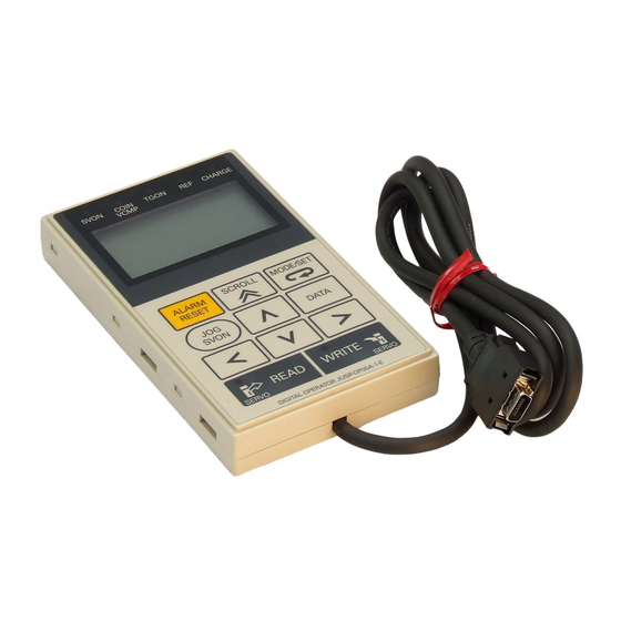
Introduction 1.1 Part Names and Functions ..........1-3 1.2 Switching Mode . - Page 19 1 Introduction The JUSP-OP05A-1-E optional digital operator for the Σ -V Series SGDV SERVOPACK is used to set and display the SERVOPACK parameters. Connect the digital operator to the CN3 connector of the SERVOPACK. JUSP-OP05A-1-E Digital Operator SVON C O I N...
-
Page 20: Part Names And Functions
WRITE SERVO SERVO DIGITAL OPERATOR JUSP-OP05A-1-E LED Display The digital operator has an LCD display with a maximum of 17 characters for each of the 5 lines. It also has 5 LED indicators to show the status of the servo ON, position- ing completion, and others. - Page 21 1 Introduction Operation Keys Operation Key Main Function Resets the alarm. (The alarm cannot be reset unless the cause of the alarm is removed.) Switches the display mode of digital operator. • Switches the cursor position between the parameter number and the setting when setting a parameter.
-
Page 22: Switching Mode
1.2 Switching Mode Switching Mode Connect the digital operator to the SERVOPACK, and turn ON the power to the SER- VOPACK. The initial display appears, and then the parameter/monitor mode display appears. Press the Key to change the mode. Power ON [Initial Display] Displayed for two seconds F i l e l i s t l o a d i n g... - Page 23 1 Introduction <NOTE> Other Alarm Displays If a communications error occurs between the SERVOPACK and digital operator, the following communications error codes are displayed. These errors may be caused by incorrect connector connection. Check the connection and correct it. Then, turn the power OFF and ON.
-
Page 24: Parameter/Monitor Modes
Parameter/Monitor Modes 2.1 Parameter Mode ........... . . 2-2 2.1.1 Parameter Setting . -
Page 25: Parameter Mode
2 Parameter/Monitor Modes 2.1.1 Parameter Setting Parameter Mode This section describes how to display and set parameters in the parameter/monitor mode. There are two types of notation used for parameters, one for parameter that requires a value setting (parameter for numeric settings) and one for parameter that requires the selection of a function (parameter for selecting functions). - Page 26 2.1 Parameter Mode Step Display after Operation Keys Operation − P R M / M O N − P n 0 0 0 = n. 0 0 0 0 Press the Key to move the cur- sor to the setting side (to the position of U n 0 0 2 = 0 0 0 0 0 the first digit of Pn000.0).
- Page 27 2 Parameter/Monitor Modes 2.1.1 Parameter Setting Operation Example 2: Setting the Parameters for Numeric Settings This example shows the operation procedure to set “1000” (min-1) for Pn304 (JOG speed). Step Display after Operation Keys Operation − P R M / M O N − U n 0 0 0 = 0 0 0 0 0 Press the...
- Page 28 2.1 Parameter Mode Step Display after Operation Keys Operation − P R M / M O N − P n 3 0 4 = 0 0 5 0 0 Press the Key twice to move the U n 0 0 2 = 0 0 0 0 0 cursor to the third digit of Pn304.
-
Page 29: Parameter Classification
2 Parameter/Monitor Modes 2.1.2 Parameter Classification 2.1.2 Parameter Classification Parameters of the Σ -V Series SERVOPACK are classified into two types of parame- ters. One type of parameters is required for setting up the basic conditions for opera- tion and the other type is required for tuning parameters that are required to adjust servomotor characteristics. -
Page 30: Monitor Mode
2.2 Monitor Mode Monitor Mode This section describes available monitor modes and operation procedures in the parameter/monitor mode. 2.2.1 Monitor Items Parameter No Content of Display Unit Un000 Motor rotating speed Un001 Speed reference Internal torque reference (in percentage to the Un002 rated torque) Rotational angle 1 (encoder pulses from the... - Page 31 2 Parameter/Monitor Modes 2.2.1 Monitor Items Parameter No Content of Display Unit − Un015 Safety input/output signal monitor Un020 Motor rated speed Un021 Motor maximum speed − Linear scale pitch Un084 Un085 (Scale pitch=Un084×10 [pm]) − Linear scale pitch index Un085 Un085 (Scale pitch=Un084×10...
- Page 32 2.2 Monitor Mode ∗2. The output signal monitor Un006 is displayed as follows. The upper portion indicates the OFF status, the lower portion indicates the ON status. The undefined digits are displayed in the lower portion (ON status). U n 0 0 6 = 8 7 6 5 4 3 2 1 digit Display Output Terminal Name...
-
Page 33: Monitor Mode Display
2 Parameter/Monitor Modes 2.2.2 Monitor Mode Display 2.2.2 Monitor Mode Display • Operation Example Select Un000 (Motor speed) on the first line, Un002 (Internal torque reference) on the second line, Un005 (Input signal monitor) on the third line, and Un006 (Output signal monitor) on the fourth line, and then save the display. - Page 34 2.2 Monitor Mode Step Display after Operation Keys Operation − P R M / M O N − U n 0 0 0 = 0 0 0 0 0 Press the Key to dis- U n 0 0 2 = 0 0 0 0 0 play Un005 (Input signal monitor).
-
Page 35: Utility Function Mode
Utility Function Mode 3.1 Outline ............. 3-3 3.2 Operations . - Page 36 3 Utility Function Mode 3.2.31 Vibration Suppression Function (Fn205) ......3-87 3.2.32 EasyFFT (Fn206) ..........3-91 3.2.33 Online Vibration Monitor (Fn207) .
-
Page 37: Outline
3.1 Outline Outline Utility functions are used to execute the functions related to servomotor operation and adjustment. Each utility function has a number starting with Fn. Utility Functions List Remarks Function Name Function ∗1 ∗2 − − Fn000 Alarm history display Displays the history up to the last 10 alarms. Runs the servomotor using the operation keys Fn002 JOG operation... - Page 38 The utility function marked with a “ ” in column *2 under Remarks is disabled when the /S-ON (Servo ON) input signal is ON. “NO-OP” is displayed when the Utility Function Mode main menu display is switched to each utility function display. ∗3. Fn01E and Fn01F can be executed only from the JUSP-OP05A-1-E digital operator.
- Page 39 3.1 Outline (cont’d) Remarks Function Name Function ∗1 ∗2 Uses a software program to internally reset the SERVOPACK and, as when the power is turned Fn030 Software reset – OFF and then ON again, to make all calcula- tions, including those for parameters. Detects polarity and stores phase information of Fn080 Polarity detection...
-
Page 40: Operations
3 Utility Function Mode 3.2.1 Alarm History Display (Fn000) Operations This section describes the operation method on the execution display selected from the main menu of the utility function. Press the Key in the parameter/monitor mode to display the main menu of utility function mode. - Page 41 3.2 Operations Preparation There are no tasks that must be performed before displaying the alarm history. Operating Procedure Use the following procedure. Step Display after Operation Keys Operation Press the Key to view the main menu for the utility function mode. Use the Key to move through the list and select Fn000.
-
Page 42: Jog Operation (Fn002)
3 Utility Function Mode 3.2.2 JOG Operation (Fn002) 3.2.2 JOG Operation (Fn002) JOG operation is used to check the operation of the servomotor under speed control without connecting the SERVOPACK to the host controller. CAUTION • While the SERVOPACK is in JOG operation, the overtravel function will be dis- abled. - Page 43 3.2 Operations (cont’d) Step Display after Operation Keys Operation Press the Key. The display changes to the Fn002 execution display. Press the Key. The cursor moves to the setting side (the right side) of Pn304 (JOG speed). Press the Key and the Key to set the JOG speed to 1000 min Press the...
- Page 44 3 Utility Function Mode 3.2.2 JOG Operation (Fn002) (cont’d) Step Display after Operation Keys Operation Press the Key. The display returns to the main menu of the utility function mode. Turn OFF the power and then turn it ON again. 3-10...
-
Page 45: Origin Search (Fn003)
3.2 Operations 3.2.3 Origin Search (Fn003) The origin search is designed to position the origin pulse position of the incremental encoder (phase C) and to clamp at the position. CAUTION • Perform origin searches without connecting the coupling. The forward run prohibited (P-OT) and reverse run prohibited (N-OT) signals are not effective in origin search mode. - Page 46 3 Utility Function Mode 3.2.3 Origin Search (Fn003) Operating Procedure Use the following procedure. Step Display after Operation Keys Operation Press the Key to view the main menu for the utility function mode. Use the Key to move through the list and select Fn003. Press the Key.
- Page 47 3.2 Operations (cont’d) Step Display after Operation Keys Operation Press the Key. The display returns to the main menu of the utility function mode. Turn OFF the power and then turn it ON again. 3-13...
-
Page 48: Program Jog Operation (Fn004)
3 Utility Function Mode 3.2.4 Program JOG Operation (Fn004) 3.2.4 Program JOG Operation (Fn004) The program JOG operation is a utility function, that allows continuous operation determined by the preset operation pattern, movement distance, movement speed, acceleration/deceleration time, waiting time, and number of times of movement. This function can be used to move the servomotor without it having to be connected to a host controller for the machine as a trial operation in JOG operation mode. - Page 49 3.2 Operations Operating Procedure Use the following procedure to perform the program JOG operation after setting a program JOG operation pattern. Step Display after Operation Keys Operation Press the Key to view the main menu for the utility function mode. Use the Key to move through the list and select Fn004.
- Page 50 3 Utility Function Mode 3.2.4 Program JOG Operation (Fn004) (cont’d) Step Display after Operation Keys Operation When the set program JOG operation movement is completed, “END” is dis- played for one second, and then “RUN” is displayed. Press the Key. The servomotor becomes baseblocked status.
-
Page 51: Initializing Parameter Settings (Fn005)
3.2 Operations 3.2.5 Initializing Parameter Settings (Fn005) This function is used when returning to the factory settings after changing parameter settings. • Be sure to initialize the parameter settings while the servo- motor power is OFF • After initialization, turn OFF the power supply and then turn ON again to validate the settings. - Page 52 3 Utility Function Mode 3.2.5 Initializing Parameter Settings (Fn005) (cont’d) Step Display after Operation Keys Operation Press the Key to initialize parameters. During initialization, “Parameter Init” is flashing in the display. After the initialization is completed, “Parameter Init” stops flashing and the status display changes as follows: “BB”...
-
Page 53: Clearing Alarm History (Fn006)
3.2 Operations 3.2.6 Clearing Alarm History (Fn006) The clear alarm history function deletes all of the alarm history recorded in the SER- VOPACK. Note: The alarm history is not deleted when the alarm reset is executed or the main circuit power supply of the SERVOPACK is turned OFF. -
Page 54: Absolute Encoder Multiturn Reset And Encoder Alarm Reset (Fn008)
3 Utility Function Mode 3.2.7 Absolute Encoder Multiturn Reset and Encoder Alarm Reset (Fn008) 3.2.7 Absolute Encoder Multiturn Reset and Encoder Alarm Reset (Fn008) CAUTION • The rotational data will be a value between -2 and +2 rotations when the absolute encoder setup is executed. - Page 55 3.2 Operations Operating Procedure Use the following procedure. Step Display after Operation Keys Operation Press the Key to view the main menu for the utility function mode. Use Key to move through the list and select Fn008. Press the Key. The display changes to the Fn008 execution dis- play.
-
Page 56: Automatic Tuning Of Analog (Speed, Torque) Reference Offset (Fn009)
3 Utility Function Mode 3.2.8 Automatic Tuning of Analog (Speed, Torque) Reference Offset (Fn009) 3.2.8 Automatic Tuning of Analog (Speed, Torque) Reference Offset (Fn009) This function measures the amount of offsets and adjusts the reference voltage auto- matically. The amount of offsets measured is saved in the SERVOPACK. Note: This function cannot be used when a position loop has been formed with a host control- ler. - Page 57 3.2 Operations (cont’d) Step Display after Operation Keys Operation Press the Key to execute the automatic adjustment of analog voltage reference (speed or torque) offset. “DONE” is displayed during the pro- R e f A d j u s t cessing, and “BB”...
-
Page 58: Manual Servo-Tuning Of Speed Reference Offset (Fn00A)
3 Utility Function Mode 3.2.9 Manual Servo-tuning of Speed Reference Offset (Fn00A) 3.2.9 Manual Servo-tuning of Speed Reference Offset (Fn00A) With this function, the speed reference offset can be adjusted by manually inputting the amount of the offset. Use this function in the following cases. •... - Page 59 3.2 Operations (cont’d) Step Display after Operation Keys Operation R U N V e l o c i t y A d j u s t Press the Key to Z A D J V = + 0 0 0 1 2 adjust the reference speed offset value.
-
Page 60: Manual Servo-Tuning Of Torque Reference Offset (Fn00B)
3 Utility Function Mode 3.2.10 Manual Servo-tuning of Torque Reference Offset (Fn00B) 3.2.10 Manual Servo-tuning of Torque Reference Offset (Fn00B) This function executes the manual adjustment or the torque reference offset value. Use this function in the following cases. • To deliberately set the offset amount to some value. •... - Page 61 3.2 Operations (cont’d) Step Display after Operation Keys Operation R U N T o r q u e A d j u s t Press the Key to Z A D J T = - 0 0 0 0 7 adjust the reference torque offset value.
-
Page 62: Offset Adjustment Of Analog Monitor Output (Fn00C)
3 Utility Function Mode 3.2.11 Offset Adjustment of Analog Monitor Output (Fn00C) 3.2.11 Offset Adjustment of Analog Monitor Output (Fn00C) This function is used to manually adjust the offsets for the analog monitor outputs (torque reference monitor output and motor speed monitor output). The offset values are factory-set before shipping. - Page 63 3.2 Operations (cont’d) Step Display after Operation Keys Operation Adjust the offset of CH2 in the same way as for CH1. Press the Key to adjust the offset of CH2. Adjust the offset so that the measure- ment instrument reading is as close to 0 V as possible.
-
Page 64: Gain Adjustment Of Analog Monitor Output (Fn00D)
3 Utility Function Mode 3.2.12 Gain Adjustment of Analog Monitor Output (Fn00D) 3.2.12 Gain Adjustment of Analog Monitor Output (Fn00D) This function is used to manually adjust the gains for the analog monitor outputs (torque reference monitor output and motor speed monitor output). The gain values are factory-set before shipping. - Page 65 3.2 Operations (cont’d) Step Display after Operation Keys Operation Adjust the gain of CH2 in the same way as for CH1. Press the Key to adjust the gain adjustment width of CH2 (motor speed monitor). After having completed the adjustment both for CH1 and CH2, press the Key.
-
Page 66: Automatic Offset-Signal Adjustment Of The Motor Current Detection Signal
3 Utility Function Mode 3.2.13 Automatic Offset-Signal Adjustment of the Motor Current Detection Signal (Fn00E) 3.2.13 Automatic Offset-Signal Adjustment of the Motor Current Detection Signal (Fn00E) Perform this adjustment only if highly accurate adjustment is required for reducing torque ripple caused by current offset. The user need not usually use this function. •... - Page 67 3.2 Operations (cont’d) Step Display after Operation Keys Operation Press the Key to start the auto- matic offset-signal adjustment of motor current detection. When the adjustment is completed, the status display shows “DONE” for one second. The status display then returns to show “BB”...
-
Page 68: Manual Offset-Signal Adjustment Of The Motor Current Detection Signal
3 Utility Function Mode 3.2.14 Manual Offset-Signal Adjustment of the Motor Current Detection Signal (Fn00F) 3.2.14 Manual Offset-Signal Adjustment of the Motor Current Detection Signal (Fn00F) Use this function only if the torque ripple is still high after the automatic offset-signal adjustment of the motor current detection signal (Fn00E). - Page 69 3.2 Operations (cont’d) Step Display after Operation Keys Operation Turn ON the servo ON (/S-ON) signal. Adjust the phase-U offset. Press the Key to adjust the offset amount. Adjust the offset amount by 10 in the direction that the torque ripple is reduced.
-
Page 70: Write Prohibited Setting (Fn010)
3 Utility Function Mode 3.2.15 Write Prohibited Setting (Fn010) 3.2.15 Write Prohibited Setting (Fn010) This function prevents changing parameters by mistake and sets restrictions on the execution of the utility function. Parameter changes and execution of the utility function become restricted in the fol- lowing manner when the write prohibited setting is set. - Page 71 3.2 Operations (cont’d) Parameter Write Prohibited Function Setting Fn01B Vibration detection level initialization Cannot be executed Fn01E Display of SERVOPACK and servomotor ID Executable Display of servomotor ID in feedback option Fn01F Executable module Fn020 Origin setting Cannot be executed Fn030 Software reset Executable...
- Page 72 3 Utility Function Mode 3.2.15 Write Prohibited Setting (Fn010) Operating Procedure Follow the steps to set enable or disable writing. Step Display after Operation Keys Operation − F U N C T I O N − Press the Key to view the main F n 0 0 F : C u r M a n u A d j menu for the utility function mode.
-
Page 73: Servomotor Model Display (Fn011)
3.2 Operations 3.2.16 Servomotor Model Display (Fn011) This function is used to check the servomotor model, voltage, capacity, encoder type, and encoder resolution. If the SERVOPACK has been custom-made, you can also check the specification codes of SERVOPACKs. Preparation There are no tasks that must be performed before the execution. Operating Procedure Use the following procedure. - Page 74 3 Utility Function Mode 3.2.16 Servomotor Model Display (Fn011) Servomotor Model 40 Linear servomotor – M o t o r l n f o – Servomotor input voltage T Y P E 4 0 A C 2 0 0 V 4 0 0 W Servomotor capacity E N C O R D E R 0 1 8 b i t...
-
Page 75: Software Version Display (Fn012)
3.2 Operations 3.2.17 Software Version Display (Fn012) This function is used to check the SERVOPACK and encoder software version num- bers. Preparation There are no tasks that must be performed before the execution. Operating Procedure Use the following procedure. Step Display after Operation Keys Operation... -
Page 76: Multiturn Limit Value Setting Change When A Multiturn Limit Disagreement
3 Utility Function Mode 3.2.18 Multiturn Limit Value Setting Change When a Multiturn Limit Disagreement Alarm Occurs (Fn013) 3.2.18 Multiturn Limit Value Setting Change When a Multiturn Limit Disagreement Alarm Occurs (Fn013) When the multiturn limit set value is changed with parameter Pn205, a multiturn limit disagreement alarm (A.CC0) will be displayed because the value differs from that of the encoder. - Page 77 3.2 Operations (cont’d) Step Display after Operation Keys Operation Press the Key. The display returns to the main menu of the utility function mode. Turn OFF the power and then turn it ON again to validate the new setting. 3-43...
-
Page 78: Resetting Configuration Errors In Option Modules (Fn014)
3 Utility Function Mode 3.2.19 Resetting Configuration Errors in Option Modules (Fn014) 3.2.19 Resetting Configuration Errors in Option Modules (Fn014) The SERVOPACK with option module recognizes installation status and types of option modules that are connected to SERVOPACK. If an error is detected, the SER- VOPACK issues an alarm. - Page 79 3.2 Operations (cont’d) Step Display after Operation Keys Operation Press the Key to clear the con- − O p t I n i t − figuration error of the option module. 0 1 : C o m m a n d O p t The error is cleared and the status dis- 0 2 : S a f e t y O p t play shows “DONE”...
-
Page 80: Vibration Detection Level Initialization (Fn01B)
3 Utility Function Mode 3.2.20 Vibration Detection Level Initialization (Fn01B) 3.2.20 Vibration Detection Level Initialization (Fn01B) This function detects vibration when servomotor is connected to a machine in opera- tion and automatically adjusts the vibration detection level (Pn312) to output more exactly the vibration alarm (A.520) and the vibration warning (A.911). - Page 81 3.2 Operations • The vibration may not be detected because of improper servo gains. Also, not all kinds of vibrations can be detected. Use the detection result as a guideline. • Set a proper moment of inertia ratio (Pn103). Improper setting may result in the vibration alarm, warning misde- tection, or non-detection.
- Page 82 3 Utility Function Mode 3.2.20 Vibration Detection Level Initialization (Fn01B) (cont’d) Step Display after Operation Keys Operation R U N Press the Key. The display changes V i b r a t i o n D e t e c t L e v e l I n i t from “Init”...
-
Page 83: Display Of Servopack And Servomotor Id (Fn01E)
3.2 Operations 3.2.21 Display of SERVOPACK and Servomotor ID (Fn01E) This function displays ID information for SERVOPACK, servomotor, encoder, and option module connected to the SERVOPACK. The ID information of some option modules (SGDV-OFA01A, for example) is not stored in the SERVOPACK. “Not available”... - Page 84 3 Utility Function Mode 3.2.21 Display of SERVOPACK and Servomotor ID (Fn01E) Operating Procedure Use the following procedure. Step Display after Operation Keys Operation − F U N C T I O N − Press the Key to view the main R U N F n 0 1 B : V i b l v l I n i t menu for the utility function mode.
-
Page 85: Display Of Servomotor Id In Feedback Option Module (Fn01F)
3.2 Operations 3.2.22 Display of Servomotor ID in Feedback Option Module (Fn01F) This function displays ID information for servomotor and encoder in Feedback Option Module connected to the SERVOPACK. If the option module is not con- nected, “Not connect” will be displayed after the module name. The following items can be displayed. - Page 86 3 Utility Function Mode 3.2.22 Display of Servomotor ID in Feedback Option Module (Fn01F) (cont’d) Step Display after Operation Keys Operation Encoder type/resolution Press the Key. − F B O p M o t I D − The encoder ID information is displayed. E n c o d e r Use the Key to scroll left...
-
Page 87: Origin Setting (Fn020)
3.2 Operations 3.2.23 Origin Setting (Fn020) When using an external absolute encoder for fully-closed loop control, this function is used to set the current position of the external absolute encoder as the origin (zero point position). This function can be used with the following products. Mitutoyo Corporation ABS ST780A series Model: ABS ST78 A/ST78 AL... -
Page 88: Software Reset (Fn030)
3 Utility Function Mode 3.2.24 Software Reset (Fn030) 3.2.24 Software Reset (Fn030) This function enables resetting the SERVOPACK internally from software. This function is used when resetting alarms and changing the settings of parameters that normally require restarting the SERVOPACK. This function can be used to change those parameters without restarting the SERVOPACK. - Page 89 3.2 Operations (cont’d) Step Display after Operation Keys Operation Press the Key to execute the soft- ware reset. After the software reset starts, S o f t w a r e R e s e t “RESET5” will no longer be displayed. After the reset has been successfully com- pleted, the screen which appears when the F i l e F i r s t L o a d i n g...
-
Page 90: Polarity Detection (Fn080)
3 Utility Function Mode 3.2.25 Polarity Detection (Fn080) 3.2.25 Polarity Detection (Fn080) This function detects the polarity and stores motor phase information in the SERVO- PACK. With this function, phase information stored in the SERVOPACK is read every time the power is turned ON, so an immediate start of operations is possible with no need to detect the polarity. - Page 91 3.2 Operations (cont’d) Step Display after Operation Keys Operation When the polarity detection is com- M a g n e t i c P o l e plete, the display shown on the left D e t e c t appears.
-
Page 92: Tuning-Less Levels Setting (Fn200)
3 Utility Function Mode 3.2.26 Tuning-less Levels Setting (Fn200) 3.2.26 Tuning-less Levels Setting (Fn200) This function sets the load level during tuning-less function. CAUTION • To ensure safety, perform the tuning-less function in a state where the SERVO- PACK can come to an emergency stop at any time. Preparation The following conditions must be met to perform the tuning-less function. - Page 93 3.2 Operations (cont’d) Step Display after Operation Keys Operation Press the Key or the Key to select the rigidity level. Select the rigidity level from 0 to 4. The larger the value, the higher the gain is and the better response performance will be. (The factory setting is 4.) Notes: •...
-
Page 94: Advanced Autotuning (Fn201)
3 Utility Function Mode 3.2.27 Advanced Autotuning (Fn201) 3.2.27 Advanced Autotuning (Fn201) This function automatically operates the servo system (in reciprocating movement in the forward and reverse directions) within set limits and adjust the SERVOPACK automatically according to the mechanical characteristics while the servo system is operating. - Page 95 3.2 Operations Operating Procedure CAUTION • When using the SERVOPACK with Jcalc = OFF (load moment of inertia is not cal- culated), be sure to set a suitable value for the moment of inertia ratio (Pn103). If the setting greatly differs from the actual moment of inertia ratio, normal control of the SERVOPACK may not be possible, and vibration may result.
- Page 96 3 Utility Function Mode 3.2.27 Advanced Autotuning (Fn201) (cont’d) Step Display after Operation Keys Operation Type Selection Select the type according to the machine element to be driven. If there is noise or the gain does not increase, better results may be obtained by changing the rigidity type. Type = 1: For belt drive mechanisms Type = 2: For ball screw drive mechanisms [Factory setting] Type = 3: For rigid systems in which the servomotor is directly coupled to the machine (without gear...
- Page 97 3.2 Operations (cont’d) Step Display after Operation Keys Operation Calculates the moment of inertia. Press the Key if a positive (+) value is set in STROKE (travel distance), or press the Key if a negative (-) value is set. Calculation of the moment of inertia will start.
- Page 98 3 Utility Function Mode 3.2.27 Advanced Autotuning (Fn201) (cont’d) Step Display after Operation Keys Operation Gain Adjustment When the Key is pressed according to the sign (+ or -) of the value set for stroke (travel distance), the calcu- lated value of the moment of inertia ratio will be saved in the SERVOPACK and the auto run operation will restart.
- Page 99 3.2 Operations When “Error” Flashes on the Display Error Probable Cause Corrective Actions • Increase the set value for Pn522. Machine vibration is occur- • Change the mode from 2 to 3. The gain adjustment ring or the positioning com- •...
- Page 100 3 Utility Function Mode 3.2.27 Advanced Autotuning (Fn201) (cont’d) Error Probable Cause Corrective Actions Display • When using the torque limit, increase the torque limit. Err4 The torque limit was reached. • Double the set value of the moment of inertia calculating start level (Pn324).
-
Page 101: Advanced Autotuning By Reference (Fn202)
3.2 Operations 3.2.28 Advanced Autotuning by Reference (Fn202) This function is used to automatically achieve optimum tuning of the SERVOPACK in response to the user reference inputs from the host controller. This function is performed generally to fine-tune the SERVOPACK after advanced autotuning of the SERVOPACK has been performed. - Page 102 3 Utility Function Mode 3.2.28 Advanced Autotuning by Reference (Fn202) Operating Procedure CAUTION • When using the MP2000 Series with phase control, select the mode = 1 (standard level). If 2 or 3 is selected, phase control of the MP2000 Series may not be possi- ble.
- Page 103 3.2 Operations (cont’d) Step Display after Operation Keys Operation Turn ON the Servo ON (/S-ON) signal. Input a reference from the host controller and then press the Key to start the adjustment. “ADJ” will flash during adjustment on the status display. Note: Adjustment cannot be performed during “BB”...
- Page 104 3 Utility Function Mode 3.2.28 Advanced Autotuning by Reference (Fn202) Failure in Operation When “NO-OP” Flashes on the Display Probable Cause Corrective Actions The main circuit power supply was OFF. Turn ON the main circuit power supply. An alarm or warning occurred. Remove the cause of the alarm or the warning.
-
Page 105: One-Parameter Tuning (Fn203)
3.2 Operations 3.2.29 One-parameter Tuning (Fn203) This function is used to manually make tuning level adjustments during operation with a position reference or speed reference input from the host controller. This function enables automatically setting related servo gain settings to balanced conditions by adjusting one or two tuning levels. - Page 106 3 Utility Function Mode 3.2.29 One-parameter Tuning (Fn203) Operating Procedure The following procedure is used for one-parameter tuning. There are the following two operation procedures depending on the tuning mode being used. • When the tuning mode is set to 0 or 1, the model following control will be disabled and one-parameter tuning will be used as the tuning method for applications other than positioning.
- Page 107 3.2 Operations Setting the Tuning Mode 0 or 1 Step Display after Operation Keys Operation Press the Key to view the main menu for the utility function mode. Press the Key to move through the list and select Fn203. Press the Key to display the Status Display moment of inertia ratio set in Pn103 at...
- Page 108 3 Utility Function Mode 3.2.29 One-parameter Tuning (Fn203) (cont’d) Step Display after Operation Keys Operation Press the Key again to display the LEVEL setting screen. If readjustment is required, select the digit with the Key or change the LEVEL with the Key.
- Page 109 3.2 Operations (cont’d) Step Display after Operation Keys Operation Press the Key to complete the one- parameter tuning operation. The display returns to the main menu of the utility function mode. Note: The status display will always be RUN when the servomotor power is ON. Setting the Tuning Mode 2 or 3 Step Display after Operation...
- Page 110 3 Utility Function Mode 3.2.29 One-parameter Tuning (Fn203) (cont’d) Step Display after Operation Keys Operation If the servomotor power is OFF, turn ON the servo ON (/S-ON) signal. The display will change from “BB” to “RUN.” If the servomotor power is ON, go to step 6. Press the Key to display the set value.
- Page 111 3.2 Operations (cont’d) Step Display after Operation Keys Operation If readjustment is required, select the digit with the Key or change the FF LEVEL and FB LEVEL with the Key. Check the response. If readjustment is not required, go to step 9. Note: The higher the FF LEVEL, the posi- tioning time will be shorter and the response will be better.
- Page 112 3 Utility Function Mode 3.2.29 One-parameter Tuning (Fn203) (cont’d) Step Display after Operation Keys Operation Press the Key to display the confirma- tion screen after level adjustment. • Press the Key to save the adjusted values. After the data is saved, “DONE” will flash for approximately two seconds and then “RUN”...
-
Page 113: Anti-Resonance Control Adjustment Function (Fn204)
3.2 Operations 3.2.30 Anti-Resonance Control Adjustment Function (Fn204) This function increases the effectiveness of the vibration suppression after one- parameter tuning. This function is effective in supporting anti-resonance control adjustment if the vibration frequencies are from 100 to 1,000 Hz. This function rarely needs to be used because it is automatically set by the advanced autotuning or advanced autotuning by reference input. - Page 114 3 Utility Function Mode 3.2.30 Anti-Resonance Control Adjustment Function (Fn204) • The tuning-less function must be disabled (Pn170.0 = 0). • The test without a motor function must be disabled (Pn00C.0 = 0). • The control must not be set to torque control. •...
- Page 115 3.2 Operations (cont’d) Step Display after Operation Keys Operation Press the Key while “Tuning Mode = 0” is displayed. The screen shown on the left will appear. The detection of vibration fre- quencies will start and “freq” will flash. Return to step 3 if vibration is not detected. Note: If vibration is not detected even when vibration is occurring, lower the vibra- tion detection sensitivity (Pn311).
- Page 116 3 Utility Function Mode 3.2.30 Anti-Resonance Control Adjustment Function (Fn204) (cont’d) Step Display after Operation Keys Operation Select the digit with the Key, and press the Key to set the damping gain. Error Error Error Torque reference Torque reference Torque reference Positioning completed Positioning completed Positioning completed...
- Page 117 3.2 Operations • With Determined Vibration Frequency Step Display after Operation Keys Operation Press the Key to view the main menu for the utility function mode. Use the Key to move through the list, select Fn204. Press the Key to display the initial set- ting screen for tuning mode.
- Page 118 3 Utility Function Mode 3.2.30 Anti-Resonance Control Adjustment Function (Fn204) (cont’d) Step Display after Operation Keys Operation Select the digit with the Key, and press the Key to adjust the damping gain. Error Error Error Torque reference Torque reference Torque reference Positioning completed Positioning completed Positioning completed...
- Page 119 3.2 Operations For Fine-tuning After Adjusting the Anti-Resonance Control Step Display after Operation Keys Operation Press the Key to view the main menu for the utility function mode. Use the Key to move through the list, select Fn204. Press the Key to display the “Tun- ing Mode = 1”...
- Page 120 3 Utility Function Mode 3.2.30 Anti-Resonance Control Adjustment Function (Fn204) (cont’d) Step Display after Operation Keys Operation Press the Key to complete the anti- resonance control adjustment function. The display returns to the main menu of the utility function mode. 3-86...
-
Page 121: Vibration Suppression Function (Fn205)
3.2 Operations 3.2.31 Vibration Suppression Function (Fn205) This function suppresses transitional vibration at frequency as low as 1 to 100 Hz that is generated mainly when positioning if the machine stand vibrates. This function is set automatically when advanced autotuning or advanced autotuning by reference is executed. - Page 122 3 Utility Function Mode 3.2.31 Vibration Suppression Function (Fn205) Preparation The following conditions must be met to perform the vibration suppression function. The message “NO-OP” indicating that the settings are not appropriate will be dis- played, if all of the following conditions are not met. •...
- Page 123 3.2 Operations (cont’d) Step Display after Operation Keys Operation Press the Key. The displayed “Mea- sure f” value will be displayed as the “Setting f” value as well. Position Error Torque reference Example of measured waveform If the vibration is not completely suppressed, select the digit with the Key, and press the...
- Page 124 3 Utility Function Mode 3.2.31 Vibration Suppression Function (Fn205) (cont’d) Step Display after Operation Keys Operation Press the Key to save the setting. “DONE” will flash for approximately two seconds and “RUN” will be displayed again. Press the Key to complete the vibration suppression function.
-
Page 125: Easyfft (Fn206)
3.2 Operations 3.2.32 EasyFFT (Fn206) This function sends a frequency waveform reference from the SERVOPACK to the servomotor and rotates the servomotor at very low speed several times over a certain period, thus causing machine vibration. The SERVOPACK detects the resonance fre- quency from the generated vibration and makes notch filter settings according to the resonance frequency detection. - Page 126 3 Utility Function Mode 3.2.32 EasyFFT (Fn206) (cont’d) Step Display after Operation Keys Operation Press the Key. The display changes to the Fn206 execution display. Note: If the display is not switched and “NO-OP” is displayed in the status display, check to make sure that the required operating conditions are being met ((1) Preparation) and take corrective action.
- Page 127 3.2 Operations (cont’d) Step Display after Operation Keys Operation When the detection processing is success- fully completed, “Measure” stops flashing and the results and the notch filter value to be set are displayed. If the processing was not completed, “No Measure” is displayed. To check the results, go to step 8.
- Page 128 3 Utility Function Mode 3.2.32 EasyFFT (Fn206) (cont’d) Step Display after Operation Keys Operation Press the Key. The servomotor enters a baseblocked sta- tus. The display returns to the main menu of the utility function mode. Turn OFF the power and then turn it ON again to validate the new setting. 3-94...
-
Page 129: Online Vibration Monitor (Fn207)
3.2 Operations 3.2.33 Online Vibration Monitor (Fn207) If vibration is generated during operation and this function is executed while the ser- vomotor power is still ON, the machine vibration can sometimes be suppressed by setting a notch filter or torque reference filter for the vibration frequencies. When online, vibration frequency caused by machine resonance will be detected and the frequency that has the highest peak will be displayed on the panel operator. - Page 130 3 Utility Function Mode 3.2.33 Online Vibration Monitor (Fn207) (cont’d) Step Display after Operation Keys Operation Press the Key for at least one sec- ond to start vibration detection. The Key must be pressed until “Measure” flashes on the display. After this message appears, the Key does not have to be pressed and the detection continues...
-
Page 131: Parameter Copy Mode
Parameter Copy Mode 4.1 Outline ............. 4-2 4.2 Operations . -
Page 132: Outline
4 Parameter Copy Mode Outline The JUSP-OP05A-1-E digital operator has a storage area of seven blocks of parame- ters with one block per SERVOPACK. The parameter copy mode can operate param- eter blocks to save parameters. Parameter Copy Mode Menus and Functions The following four functions can be executed in parameter copy mode. -
Page 133: Operations
4.2 Operations Operations This section describes the operation method on the execution display selected from the main menu of the parameter copy mode. Press the Key to display the parameter copy mode menu. Press the Key to select a menu to be executed, and press the Key to switch the display to the corresponding menu execution display. - Page 134 4 Parameter Copy Mode 4.2.1 Read-out Parameters from SERVOPACK (SERVO → OP) (cont’d) Step Display after Operation Keys Operation Press the Key. − S E R V O → O P − The display changes to the execution dis- 0 0 : ∗ ∗ ∗ ∗ play.
- Page 135 4.2 Operations Notes on Read-out Parameters Function • If the parameter block which has been already saved is selected, and read-out parameter function is executed, the parameter block is overwritten. • Press the Key to cancel the operation while reading parameters. “Canceled” is displayed and the display returns to the parameter block selection display.
-
Page 136: Write-In Parameters (Op → Servo)
4 Parameter Copy Mode 4.2.2 Write-in Parameters (OP → SERVO) 4.2.2 Write-in Parameters (OP → SERVO) The selected block of parameters saved in the digital operator are written into the SERVOPACK. Operating Procedure Step Display after Operation Keys Operation Open the parameter copy mode menu −... - Page 137 4.2 Operations (cont’d) Step Display after Operation Keys Operation When the parameters were read out from − O P → S E R V O − A . 9 4 1 the specified block in digital operator, 0 0 : S G D V − R 7 0 and saved in the SERVOPACK, “Com- pleted”...
- Page 138 4 Parameter Copy Mode 4.2.2 Write-in Parameters (OP → SERVO) Notes on Write-in Parameters Function • Do not disconnect the digital operator from the SERVOPACK while the parame- ters are being written in. Otherwise, the writing process is cancelled, and a part of parameters are not written in.
-
Page 139: Verify Parameters (Verify)
4.2 Operations 4.2.3 Verify Parameters (VERIFY) The parameters of the selected block saved in the digital operator and those in the SERVOPACK are verified, and the result is displayed. Operating Procedure Step Display after Operation Keys Operation Open the parameter copy mode menu −... - Page 140 4 Parameter Copy Mode 4.2.3 Verify Parameters (VERIFY) (cont’d) Step Display after Operation Keys Operation When the verification of the parameters − V E R I F Y − read out from the digital operator, the parameters read out from the SERVO- 0 0 : S G D V −...
- Page 141 4.2 Operations Notes on Verify Parameters Function ∗∗∗∗ • If an empty block (“ ”) is selected and the verify function is executed, the mes- sage “No Data” is displayed, and the verification will not be executed. Press Key to return to the parameter block selection display. •...
-
Page 142: Parameter Block List Display (List)
4 Parameter Copy Mode 4.2.4 Parameter Block List Display (LIST) 4.2.4 Parameter Block List Display (LIST) The statuses of one of seven parameter blocks in the storage area of digital operator are displayed in a list, and unnecessary parameter blocks can be deleted. Operating Procedure Step Display after Operation... - Page 143 4.2 Operations (cont’d) Step Display after Operation Keys Operation When the selected parameter block is − L I S T − deleted, “Completed” is displayed. 0 0 : S G D V − R 7 0 C o m p l e t e d After “Completed”...
-
Page 144: Revision History
Revision History The revision dates and numbers of the revised manuals are given on the bottom of the back cover. MANUAL NO. SIEP S800000 55A <1>-1 WEB revision number Revision number Published in Japan September 2009 Date of publication Date of Rev. - Page 145 Phone 81-4-2962-5151 Fax 81-4-2962-6138 http://www.yaskawa.co.jp YASKAWA AMERICA, INC. 2121, Norman Drive South, Waukegan, IL 60085, U.S.A. Phone 1-800-YASKAWA (927-5292) or 1-847-887-7000 Fax 1-847-887-7310 http://www.yaskawa.com YASKAWA ELÉTRICO DO BRASIL LTDA. 777, Avenida Piraporinha, Diadema, São Paulo, 09950-000, Brasil Phone 55-11-3585-1100 Fax 55-11-3585-1187 http://www.yaskawa.com.br...
Need help?
Do you have a question about the JUSP-OP05A-1-E and is the answer not in the manual?
Questions and answers