
Related Manuals for YASKAWA SGM-A3


Summary of Contents for YASKAWA SGM-A3
- Page 1 YASKAWA Series SGM/SGMP/DR2 USER'S MANUAL AC Servomotors and Driver SGM/SGMP Servomotors DR2 Servopack YASKAWA MANUAL NO. TSE-S800-17D...
- Page 2 Such modification is made as a revision by renewing the manual No. S To order a copy of this manual, if your copy has been damaged or lost, contact your YASKAWA representative listed on the last page stating the manual No. on the front cover.
- Page 3 NOTES FOR SAFE OPERATION Read this manual thoroughly before installation, operation, maintenance or inspection of the AC Servo Drives. In this manual, the NOTES FOR SAFE OPERATION are classified as “WARNING” or “CAUTION”. WARNING Indicates a potentially hazardous situation which, if not avoided, could result in death or serious personal inju- CAUTION Indicates a potentially hazardous situation which, if not avoided, may result in minor or moderate personal injury and/or damage to the equipment.
- Page 4 WARNING (INSTALLATION) S After voltage resistance test, wait at least five minutes before servicing the product. Failure to observe this warning may result in electric shock. (WIRING) S Grounding must be in accordance with the national code and consistent with sound local practices. Failure to observe this warning may lead to electric shock or fire.
- Page 5 CAUTION (OPERATION) S To avoid inadvertent accidents, run the SERVOMOTOR only in test run (without load). Failure to observe this caution may result in personal injury. S Before starting operation with a load connected, set up user constants suitable for the machine. Starting operation without setting up user constants may lead to overrun failure.
-
Page 6: Chapter 1 For First-Time Users Of Ac Servos
Manual Contents This manual provides Σ-Series users with information on the following: • An overview of servo systems for first-time users. • Checking the product on delivery and basic applications of the servo. • Servo applications. • Selecting an appropriate servo for your needs and placing an order. •... - Page 7 APPENDIXES A Differences between DR2 and DR1, SGDA and SGD Servopacks ..........
- Page 8 Unless otherwise specified, the following definitions are used: Servomotor: Σ-Series SGM/SGMP Servomotor Servopack: An amplifier (Trademark of Yaskawa servo amplifier “DR2 Servopack”) Servodrive: A SGM/SGMP Servomotor and an amplifier (DR2 Servopack) Servo system: A complete servo control system consisting of servodrive, host controller,...
- Page 9 Yas- kawa. No patent liability is assumed with respect to the use of the information contained herein. Moreover, because Yaskawa is constantly striving to improve its high-quality products, the information contained in this manual is subject to change without notice.
-
Page 10: Table Of Contents
CONTENTS CHAPTER 1 FOR FIRST-TIME USERS OF AC SERVOS ....Basic Understanding of AC Servos ......... . 1.1.1 Servo Mechanisms . - Page 11 CONTENTS Setting Stop Mode ............3.4.1 Adjusting Offset .
- Page 12 CONTENTS Using the Functions ............4.2.1 Operation in Alarm Trace-back Mode .
- Page 13 CONTENTS 5.6.14 Encoder Signal Converter Unit ........5.6.15 Cables for Connecting PC and Servopack .
- Page 14 CONTENTS List of Alarm Displays ........... . Relationship between Reference Forms and User Constants .
- Page 15 FOR FIRST-TIME USERS OF AC SERVOS This chapter is intended for first-time users of AC servos. It describes the ba- sic configuration of a servo mechanism and basic technical terms relating to servos. Users who already have experience in using a servo should also take a look at this chapter to understand the features of Σ-Series AC Servos.
-
Page 16: Basic Understanding Of Ac Servos
FOR FIRST-TIME USERS OF AC SERVOS 1.1.1 Servo Mechanisms Basic Understanding of AC Servos This section describes the basic configuration of a servo mechanism and technical terms relating to servos and also explains the features of Σ-Series AC Servos. 1.1.1 Servo Mechanisms . - Page 17 1.1 Basic Understanding of AC Servos Servo system could be defined in more detail as a mechanism that: • Moves at a specified speed and • Locates an object in a specified position To develop such a servo system, an automatic control system involving feedback control must be designed.
- Page 18 General servomotors or Yaskawa SGM/SGMP Servomotors. In some cases, a position detector (encoder) is included in a servomotor. Servopack Trademark of Yaskawa servo amplifier “DR2 Servopack.” Servo drive A Servomotor and amplifier pair. Also called “servo.” Servo system A closed control system consisting of a host controller, servo drive and controlled system to form a servo mechanism.
-
Page 19: Servo Configuration
1.1 Basic Understanding of AC Servos 1.1.2 Servo Configuration 1) Configuration of Servo System The following diagram illustrates a servo system in detail: Host controller Position or speed reference Servo amplifier Comparator Power amplifier (Output) Position Motor drive (Input) circuit Speed Movable Gear... - Page 20 FOR FIRST-TIME USERS OF AC SERVOS 1.1.2 Servo Configuration cont. Servo components (1) to (5) are outlined below: (1) Controlled system In the previous figure, the controlled system is a movable table for which the position or speed is controlled. The movable table is driven by a ball screw and is connected to the servomotor via gears.
- Page 21 The following figure illustrates the structure of a synchronous type servomotor: Light-receiving Rotary disc element Armature Housing Front cap wire Light-emitting Stator core element Ball bearing Shaft Rotor core Magnet Position detector Lead wire (encoder) Yaskawa SGM and SGMP Servomotors are of the synchronous type.
- Page 22 FOR FIRST-TIME USERS OF AC SERVOS 1.1.2 Servo Configuration cont. (c) Performance of Servomotor A servomotor must have “instantaneous power” so that it can start as soon as a start reference is received. The term “power rating (kW/s)” is used to represent instantaneous power. It refers to the electric power (kW) that a servomotor generates per second.
- Page 23 1.1 Basic Understanding of AC Servos (4) Servo amplifier A servo amplifier is required to operate an AC servomotor. The following figure illustrates the configuration of a servo amplifier: Servo amplifier Motor driving AC power Power amplifier Comparator Reference input Feedback Servomotor Commercial AC power...
- Page 24 A host controller controls a servo amplifier by specifying a position or speed as a set point. For speed reference, a position control loop may be formed in the host controller when a position feedback signal is received. Yaskawa PROGIC-8 is a typical host controller. PROGIC-8 TERMS A programmable machine controller.
-
Page 25: Features Of Σ-Series Servos
1.1 Basic Understanding of AC Servos 1.1.3 Features of Σ-Series Servos 1) Σ-Series SGM/SGMP Servomotors are synchronous type servomotors and have the fol- lowing features: • Size and weight reduced to one-third those of our conventional models. Compact Servomotor for saving installation space. - Page 26 In this way, the host controller can freely perform the control required for the servo mech- anism. The Servopack undertakes the speed control loop and subsequent control processing. Yaskawa programmable machine controller PROGIC-8 is available as a typical host con- troller.
- Page 27 1.1 Basic Understanding of AC Servos 4) Speed/torque control Servopack can also provide torque control as shown below. • Using Servopack in Speed/Torque Control Mode (Torque Control) Host controller Position monitoring Position Torque Servopack information reference (speed/torque control) Power amplifier (Analog voltage) Speed Servomotor...
- Page 28 FOR FIRST-TIME USERS OF AC SERVOS 1.1.3 Features of Σ -Series Servos cont. 5) Position control Servopack can be used as below. • Using Servopack in Position Control Mode Host controller Position monitoring Position reference Servopack (position control) Position information Power amplifier Servomotor...
-
Page 29: Chapter 2 Basic Uses Of Σ-Series Products
BASIC USES OF Σ-SERIES PRODUCTS This chapter describes the first things to do when Σ-Series products are deliv- ered. It also explains the most fundamental ways of connecting and operating Σ-Series products. Both first-time and experienced servo users must read this chapter. -
Page 30: Precautions
BASIC USES OF Σ-SERIES PRODUCTS 2.1.1 Notes on Use Precautions This section provides notes on using Σ-Series products. 2.1.1 Notes on Use ........... 2.1.1 Notes on Use NOTE Always note the following to ensure safe use. - Page 31 2.1 Precautions Always follow the specified installation method. Provide sufficient clearance 10 mm The Servopack generates heat. Install the Servo- pack so that it can radiate heat freely. Note also that the Servopack must be in an environment free from condensation, vibration and shock. Ambient temperature: 0 to 55°C...
-
Page 32: Installation
BASIC USES OF S-SERIES PRODUCTS 2.2.1 Checking on Delivery Installation This section describes how to check S-Series products on delivery and how to install them. 2.2.1 Checking on Delivery ..........2.2.2 Installing the Servomotor . -
Page 33: Installing The Servomotor
2.2 Installation Appearance Nameplate Type D R 2 - 0 1 A C P - F Servopack type Σ-Series DR2 Servopack Rated Ouoput A3:0.04HP A5:0.07HP 01:0.13HP 02:0.27HP 03:0.40HP 04:0.53HP Servo- 08:1.01HP Power Supply pack Type C: Incremental/absolute encoder available Serial number Applicable motor Output power voltage Blank: SGM Servomotor... - Page 34 BASIC USES OF Σ-SERIES PRODUCTS 2.2.2 Installing the Servomotor cont. Installation sites: The Servomotor SGM and SGMP types are designed for indoor use. Install Servomotor in an environment which meets the following conditions: a) Free from corrosive and explosive gases b) Well-ventilated and free from dust and moisture c) Ambient temperature of 0 to 40°C d) Relative humidity of 20% to 80% (non-condensing)
- Page 35 2.2 Installation • Servomotor with incremental encoder Allowable Allowable Radial Load Thrust Load Motor Type Reference Drawing Fr [N(lb)] Fs [N(lb)] (in.) SGM-A3 68 (15) 54 (12) 20 (0.82) SGM-A5 68 (15) 54 (12) 20 (0.82) SGM-01 78 (17) 54 (12) 20 (0.82)
-
Page 36: Installing The Servopack
BASIC USES OF Σ-SERIES PRODUCTS 2.2.3 Installing the Servopack 2.2.3 Installing the Servopack Σ-Series DR2 Servopack is a rack−mounted type ser- vo controller. Incorrect installation will cause problems. Always ob- serve the installation instructions described in the next page. DR2 Servopack Storage: When the Servopack is to be stored with the power cable disconnected, store it in the following temperature range:... - Page 37 2.2 Installation Installation method: When installing multiple Servopacks side by side in a control panel, observe the following installation method: 50 mm or more 30 mm or more 50 mm or more 10 mm or more a) Install Servopack perpendicularly so that the front panel (containing connectors) faces outward.
- Page 38 BASIC USES OF Σ-SERIES PRODUCTS 2.2.3 Installing the Servopack cont. c) When installing Servopacks side by side, provide at least 10 mm space between them and at least 50 mm space above and below them as shown in the figure above. Install cooling fans above the Servopacks to prevent the temperature around each Servopack from increasing excessively and also to maintain the temperature inside the control panel evenly.
-
Page 39: Connection And Wiring
2.3 Connection and Wiring Connection and Wiring This section describes how to connect Σ-Series products to peripheral devices and explains a typical example of wiring the main circuit. It also describes an example of connecting to main host controllers. 2.3.1 Connecting to Peripheral Devices . - Page 40 BASIC USES OF S-SERIES PRODUCTS Standard connection method for S-Series AC Servo Drives: Molded-case circuit breaker (MCCB) Power supply: Digital Operator Single-phase Used to protect power 200 or 100 V supply line. Shuts the Allows the user circuit off when to set user overcurrent is detected.
- Page 41 Host controller Servopack is compatible with most P.L.C.motion controllers and indexers. Personal computer References are input as analog signals or pulse trains. Exclusive-use cable between personal computer and Servo- pack (for NEC PC) is available. Type: DE9405258 (2m, 6.6ft.) consult factory about cable for IBM PC.
-
Page 42: Main Circuit Wiring And Power On Sequence
BASIC USES OF Σ-SERIES PRODUCTS 2.3.2 Main Circuit Wiring and Power ON Sequence 2.3.2 Main Circuit Wiring and Power ON Sequence 1) The following diagram shows a typical example of wiring the main circuit for Σ-Series products: For 100 V Type + 10 + 10 Single-phase 100 to 115 VAC... - Page 43 2.3 Connection and Wiring 3) Form a power ON sequence as follows: a) Form a power ON sequence so that the main power is turned OFF when a servo alarm signal is output. (See the circuit diagram shown on the previous page.) b) Hold down the power ON push-button for at least two seconds.
-
Page 44: Examples Of Connecting I/O Signal Terminals
2) Example of Connecting to PROGIC-8 Servopack for Speed Control Servopack Speed (MADE BY YASKAWA) FG (connector frame) *1 These pin numbers are also applicable to SV2 to SV4. *2 Do not change the standard settings of user constants for the Servopack. - Page 45 2.3 Connection and Wiring 3) Example of Connecting to GL-Series Positioning Module B2833 Servopack for Speed Control SERVOPACK Speed (MADE BY YASKAWA) SERVO NORMAL DECEL LS D/A OUTPUT *1 These signals are output for ALARM approximately two seconds when the power is turned ON.
- Page 46 BASIC USES OF Σ-SERIES PRODUCTS 2.3.3 Examples of Connecting I/O Signal Terminals cont. 4) Example of Connecting to GL-Series Positioning Module B2813 Servopack for Position Control Servopack Positions (MADE BY YASKAWA) SERVO NORMAL DECEL LS ALARM *1 These signals are output for approximately two seconds when the power is turned ON.
- Page 47 * These signals are output for approximately two seconds when the power is turned ON. Take this into consideration when designing a power ON sequence. Relay 1Ry is used to stop main circuit power supply to Servopack. Note The signals shown here are applicable only to OMRON Sequencer C500-NC222 and Yaskawa Servopack DR2-VVVV.
- Page 48 *2 Change the Cn-02 setting as follows: Bit No. 3 = 1 Bit No. 4 = 0 Bit No. 5 = 0 *3 Manufactured by Yaskawa Controls Co., Ltd. Note The signals shown here are applicable only to OMRON Sequencer C500-NC112 and Yaskawa Servopack DR2-VVVV.
- Page 49 2.3 Connection and Wiring 7) Example of Connecting to MITSUBISHI Positioning Unit AD72 Servopack for Speed Control SERVOPACK Speed I/O POWER SUPPLY (MADE BY MITSUBISHI) AD72 (ON when position- ing is stopped) (ON when proximity is detected) SPEED REF- ERENCE *1 These signals are output for approximately two seconds when the power is turned ON.
- Page 50 ON sequence. Relay 1Ry is used to stop main circuit power supply to Servopack. *2 Manufactured by Yaskawa Controls Co., Ltd. Note The signals shown here are applicable only to MITSUBISHI Sequencer AD71 (B Type)
-
Page 51: Conducting A Test Run
2.4 Conducting a Test Run Conducting a Test Run This section describes how to conduct a full test run. The test run is divided into two steps. Complete a test run in step 1 first, then proceed to step 2. 2.4.1 Test Run in Two Steps . - Page 52 BASIC USES OF Σ-SERIES PRODUCTS 2.4.1 Test Run in Two Steps cont . Step 1: Conducting a test run for the motor without load . . . Check that the motor is wired correctly. Conduct a test run with the motor shaft disconnected Operate the motor with a from the machine.
-
Page 53: Step 1: Conducting A Test Run For Motor Without Load
2.4 Conducting a Test Run 2.4.2 Step 1: Conducting a Test Run for Motor without Load Check that the motor is wired correctly. If the motor fails to rotate properly during a servo drive test run, the cause most frequently lies in incorrect wiring. - Page 54 BASIC USES OF Σ-SERIES PRODUCTS 2.4.2 Step 1: Conducting a Test Run for Motor without Load cont. (4) Turn the power ON. Turn the Servopack power ON. If the Servo- pack is turned ON normally, the LED on the Digital Operator lights up as shown in the fig- ure.
- Page 55 2.4 Conducting a Test Run If the signal lines below are not wired correctly, the motor fails to rotate. Always wire them correctly. (If signal lines are not to be used, short them as necessary.) P-OT 1CN-42 Motor can rotate in forward direction when this input signal is at 0 V. N-OT 1CN-43 Motor can reverse when this input signal is at 0 V.
- Page 56 BASIC USES OF Σ-SERIES PRODUCTS 2.4.2 Step 1: Conducting a Test Run for Motor without Load cont. (2) Check the following items in monitor mode (Refer to 4.6.1.): (1) Has a reference speed been input? (2) Is the motor speed as designed? (3) Does the reference speed match the actual motor speed? (4) Does the motor stop when no reference is input? Un-00...
-
Page 57: Step 2: Conducting A Test Run With The Motor Connected To The Machine
2.4 Conducting a Test Run (3) Check the following items in monitor mode (Refer to 4.6.1.): (1) Has a reference pulse been input? (2) Is the motor speed as set? (3) Does the reference speed match the actual motor speed? (4) Does the motor stop when no reference is input? Un-00 Actual motor speed... - Page 58 BASIC USES OF Σ-SERIES PRODUCTS 2.4.3 Step 2: Conducting a Test Run with the Motor Connected to the Machine cont. NOTE Before proceeding to step 2, repeat step 1 (conducting a test run for the motor without load) until you are fully satisfied that the test has been completed successfully. Operation faults that arise after the motor is connected to the machine not only damage the machine but may also cause an accident resulting in injury or death.
-
Page 59: Supplementary Information On Test Run
2.4 Conducting a Test Run 2.4.4 Supplementary Information on Test Run In the following cases, always refer to the information described below before starting a test run: • When using a servomotor with a brake • When performing position control from the host controller 1) When using a servomotor with brake The brake prevents the motor shaft from rotating due to a backdriving torque. - Page 60 BASIC USES OF Σ-SERIES PRODUCTS 2.4.4 Supplementary Information on Test Run cont. 2) When performing position control from the host controller Check motor operation first and then conduct a test run as described in the table below. Type: DR2−jjjj GOOD POOR Speed reference...
-
Page 61: Minimum User Constants Required And Input Signals
2.4 Conducting a Test Run 2.4.5 Minimum User Constants Required and Input Signals 1) This section describes the minimum user constants that must be set to conduct a test run. For details on how to set each user constant, refer to 4.1.5 Operation in User Constant Setting Mode. -
Page 62: Chapter 3 Applications Of Σ-Series Products
APPLICATIONS OF Σ-SERIES PRODUCTS This chapter is prepared for readers who wish to learn more about the applica- tions of Σ-series products after fully understanding Chapter 2 Basic Uses of Σ-series Products. It explains how to set user constants for each purpose and how to use each function. - Page 63 Chapter Table of Contents, Continued 3.4.2 Using Dynamic Brake ......3.4.3 Using Zero-Clamp .
-
Page 64: Before Reading This Chapter
Before Reading this Chapter 1) This chapter describes how to use each 1CN connector I/O signal for the DR2 Servopack and how to set the corresponding user constant. 2) For a list of I/O signals of 1CN connecor, refer to Appendix C List of I/O Signals. For terminal arrangement for I/O signals of 1CN connecor, refer to 3.8.8 Connector Ter- minal Layouts. -
Page 65: Setting User Constants According To Machine Characteristics
APPLICATIONS OF Σ-SERIES PRODUCTS 3.1.1 Changing the Direction of Motor Rotation Setting User Constants According to Machine Characteristics This section describes how to set user constants according to the dimensions and performance of the machine to be used. 3.1.1 Changing the Direction of Motor Rotation . - Page 66 3.1 Setting User Constants According to Machine Characteristics 3) Setting Reverse Rotation Mode: Reverse rotation mode can be set in either of the following two ways. Normally, method 1 is easier to use. a) Method 1: Setting Memory Switch Set bit 0 of memory switch Cn-02 to select reverse rotation mode. Cn-02 Bit 0 Rotation Direction Factory...
-
Page 67: Setting The Overtravel Limit Function
APPLICATIONS OF Σ-SERIES PRODUCTS 3.1.2 Setting the Overtravel Limit Function 3.1.2 Setting the Overtravel Limit Function 1) The overtravel limit function forces the moving part of the machine to stop when it ex- ceeds the movable range. 2) To use the overtravel limit function, connect the following input signal terminals correctly. Forward Rotation Prohibited For Speed/Torque →... - Page 68 3.1 Setting User Constants According to Machine Characteristics 3) Use the following user constants (memory switch) to specify whether input signals for overtravel are to be used. Use of P-OT Input Signal Factory For Speed/Torque Control Cn-01 Bit 2 Setting: 0 and Position Control Use of N-OT Input Signal Factory...
- Page 69 APPLICATIONS OF Σ-SERIES PRODUCTS 3.1.2 Setting the Overtravel Limit Function cont. Setting Meaning Stops the motor in the same way as when the servo is turned OFF. The motor is stopped by dynamic brake or coasts to a stop. Either of Cn-01 these stop modes can be selected by setting bit 6 of Cn-01.
-
Page 70: Restricting Torque
3.1 Setting User Constants According to Machine Characteristics If dynamic brake stop mode is selected, specify the operation to be performed when the motor stops. Setting Meaning Releases dynamic brake after the motor stops. Cn-01 Cn-01 bit 7 Does not release dynamic brake even after the motor stops. 3.1.3 Restricting Torque 1) The Servopack can provide the following torque control: D Torque restriction... - Page 71 APPLICATIONS OF Σ-SERIES PRODUCTS 3.1.3 Restricting Torque cont. Sets the maximum torque values for forward rotation and reverse rotation, Output Signal for Torque Restric- respectively. tion Function Sets these user constants when torque D CLT+ (1CN-25), CLT- (1CN-26) must be restricted according to ma- chine conditions.
- Page 72 3.1 Setting User Constants According to Machine Characteristics Preset Value: Cn-08 (TLMTF) Cn-09 (TLMTR) Cn-18 (CLMIF) : P-CL input only Cn-19 (CLMIR) : N-CL input only Note This function is changed to another function depending on the setting of bit 4 of memory switch Cn-01.
- Page 73 APPLICATIONS OF Σ-SERIES PRODUCTS 3.1.3 Restricting Torque cont. 3) How to Set Level 2: External Torque Limit First, use a contact input signal to make the torque Servopack (current) limit value set in the user constant valid. Without Torque limit can be set separately for forward and Forward torque limit rotation...
- Page 74 3.1 Setting User Constants According to Machine Characteristics CLMIF Unit: Setting Factory For Speed/Torque Forward External Range: 0 to Setting: Control and Position Cn-18 Torque Limit Maximum Control Torque CLMIR Unit: Setting Factory For Speed/Torque Reverse External Range: 0 to Setting: Control and Position Cn-19...
- Page 75 APPLICATIONS OF Σ-SERIES PRODUCTS 3.1.3 Restricting Torque cont. ON: 1CN-45 is at Torque restriction applies during forward rotation. Limit value: low level. Cn-18 P CL P-CL OFF: 1CN-45 is at Torque restriction does not apply during forward high level. rotation. Normal operation status. ON: 1CN-46 is at Torque restriction applies during reverse rotation.
- Page 76 3.1 Setting User Constants According to Machine Characteristics • Handling of the CLT+, CLT- signals are the same as for level 1 (internal torque limit). Refer to Using CLT+, CLT- Signals on page 58.
-
Page 77: Setting User Constants According To Host Controller
APPLICATIONS OF Σ-SERIES PRODUCTS 3.2.1 Inputting Speed Reference Setting User Constants According to Host Controller This section describes how to connect a Σ-series Servo to a host controller and how to set user constants. 3.2.1 Inputting Speed Reference ........3.2.2 Inputting Position Reference . - Page 78 3.2 Setting User Constants According to Host Controller Speed Reference Input For Speed/Torque → Input V-REF 1CN-5 Control Only Signal Ground for Speed For Speed/Torque → Input SG-V 1CN-6 Reference Input Control Only Use these signals when speed control is selected 4500 (memory switch Cn-02 bit B = 0).
- Page 79 APPLICATIONS OF Σ-SERIES PRODUCTS 3.2.1 Inputting Speed Reference cont. 3) Use the memory switch and input signal P-CON to specify one of the four modes shown below. Cn-01 Bit A Control Mode Selection Factory For Speed/Torque Control Setting: 0 Only Cn-01 Bit B Control Mode Selection Factory...
- Page 80 3.2 Setting User Constants According to Host Controller Cn-01 Setting Control Mode Control Mode Bit B Bit A Speed Control DR2 Servopack This is normal speed control. Speed reference V-REF (1CN-5) D Speed reference is input from V-REF P/PI changeover P-CON (1CN-5).
- Page 81 APPLICATIONS OF Σ-SERIES PRODUCTS 3.2.1 Inputting Speed Reference cont. • Using P-CON Signal: Proportional Control, etc. For Speed/Torque → Input P-CON 1CN-41 Control and Position Control The function of input signal P-CON changes with the memory switch setting. Servopack Switching between P control and PI control Switching between zero-clamp enabled mode and zero-clamp prohibited mode Switching between torque control and speed control...
-
Page 82: Inputting Position Reference
3.2 Setting User Constants According to Host Controller 3.2.2 Inputting Position Reference 1) Using the following memory switch, select the position control. Selection of Speed/Torque Factory For Speed/Torque Control Cn-02 Bit B Control or Position Control Setting: 0 and Position Control Select the control mode (speed/torque control or position control) by bit B of memory switch Cn-02. - Page 83 APPLICATIONS OF Σ-SERIES PRODUCTS 3.2.2 Inputting Position Reference cont. Connection Example 2: Open Collector Output Sets the value of limiting re- Host controller Servopack sistor R1 so that input cur- rent i falls within the following range: 1CN-7 Photocoupler 1CN-8 Input Current i: 7 to 15 mA Examples: 1CN-11...
- Page 84 3.2 Setting User Constants According to Host Controller Connection Example 3: When Power for Open Collector Reference is Used When power for open collec- Host controller Servopack tor reference (PL1, PL2, Photo- coupler PL3) is used, connect be- tween PL1 and PULS, PL2 and SIGN, PL3 and CLR as follows: ↕P: Represents twisted-pair cables...
- Page 85 APPLICATIONS OF Σ-SERIES PRODUCTS 3.2.2 Inputting Position Reference cont. Input Refer- Cn-02 Motor Forward Motor Forward Motor Reverse Motor Reverse Pulse Pulse ence ence Multipli- Pulse Run Reference Run Reference Bit D Form Sign + pulse (1CN-7) train (1CN-7) (1CN-11) (1CN-11) Two- phase...
- Page 86 3.2 Setting User Constants According to Host Controller Input Pulse Multiply Function: Number of motor move When the reference form is two-phase pulse pulses train with 90° phase difference, the input pulse multiply function can be used. Input reference pulse (1CN-7) The electronic gear function can also be used (1CN-11)
- Page 87 APPLICATIONS OF Σ-SERIES PRODUCTS 3.2.2 Inputting Position Reference cont. Allowable Voltage Level and Timing for Reference Pulse Input Reference Pulse Form Electrical Specifications Remarks Sign + pulse train input The signs for each (SIGN + PULS signal) reference pulse are as follows: Maximum reference ¨: High level...
- Page 88 3.2 Setting User Constants According to Host Controller Error Counter Clear Signal Factory For Position Control Only Cn-02 Bit A Selection Setting: 0 Selects the pulse form of error counter clear signal CLR (1CN-15). Setting Meaning Clears the error counter when the CLR signal is set at high level.
-
Page 89: Using Encoder Output
APPLICATIONS OF Σ-SERIES PRODUCTS 3.2.3 Using Encoder Output 3.2.3 Using Encoder Output 1) Encoder output signals divided inside the Servopack can be output externally. These signals can be used to form a position control loop in the host controller. This output is explained here. - Page 90 3.2 Setting User Constants According to Host Controller 2) I/O signals are described below. Encoder Output For Speed/Torque Control Output → PAO 1CN-33 Phase-A and Position Control Encoder Output For Speed/Torque Control Output → £ PAO 1CN-34 Phase-A and Position Control Encoder Output For Speed/Torque Control Output →...
- Page 91 APPLICATIONS OF Σ-SERIES PRODUCTS 3.2.3 Using Encoder Output cont. SEN Signal Input For Speed/Torque Control → Input SEN 1CN-4 and Position Control SEN Signal Input For Speed/Torque Control → Input 0SEN 1CN-2 and Position Control Encoder Output For Speed/Torque Control Output →...
- Page 92 3.2 Setting User Constants According to Host Controller 4) Set the pulse dividing ratio in the following user constant. PGRAT Unit: Setting Factory For Speed/Torque Dividing Ratio Setting Range: 16 Setting: Control and Position Cn-0A to No. of 2048 Control Encoder Pulses Sets the number of output pulses for PG output...
-
Page 93: Using Contact I/O Signals
There are no power terminals to which the DR2 Servopack outputs signals exter- nally. External Power Supply: 24 1 VDC 50 mA or more Yaskawa recommends that this external power supply be the same type as for the output circuit. I/O Power Supply For Speed/Torque →... - Page 94 Note Provide an external I/O power supply separately. There are no power terminals to which the DR2 Servopack outputs signals exter- nally. Yaskawa recommends that this external power supply be the same type as for the input circuit. Signal Ground for Alarm For Speed/Torque Output →...
-
Page 95: Using Electronic Gear
APPLICATIONS OF Σ-SERIES PRODUCTS 3.2.5 Using Electronic Gear 3.2.5 Using Electronic Gear For position control only. 1) Outline Positions The electronic gear function enables the motor travel distance per input reference pulse to be set to any value. It allows the host controller to perform control without having to consider the machine gear ratio and the number of encoder pulses. - Page 96 3.2 Setting User Constants According to Host Controller c) Determine the reference unit to be used. Reference unit is the minimum unit of posi- To move a table in 0.001 mm units Reference unit: 0.001 mm tion data used for moving the load. (Minimum unit of reference from host con- troller) Examples:...
- Page 97 APPLICATIONS OF Σ-SERIES PRODUCTS 3.2.5 Using Electronic Gear cont. f) Set the electronic gear ratio in the user constants below. Reduce the electronic gear ratio to their lowest terms so that both A and B are an integer smaller than 65535, then set A and B in the following user constants. ...
- Page 98 3.2 Setting User Constants According to Host Controller 3) Examples of Setting an Electronic Gear Ratio for Different Load Mechanisms Ball Screw Reference unit: 0.001 mm Travel distance per = 6000 0.001mm revolution of load shaft = 2048 × 4 × 1 = Cn-24 Load shaft Electronic gear ratio...
-
Page 99: Using Contact Input Speed Control
APPLICATIONS OF Σ-SERIES PRODUCTS 3.2.6 Using Contact Input Speed Control 3.2.6 Using Contact Input Speed Control 1) The contact input speed control function provides easy-to-use speed control. It allows the user to initially set three different motor speeds in user constants, select one of the speeds externally by contact input and run the motor. - Page 100 3.2 Setting User Constants According to Host Controller Setting Meaning Input Signal P-CON(1CN-41) Used to switch between P control and PI Does not use the control. contact input contact input speed control speed control P-CL(1CN-45) Used for forward external torque limit input function.
- Page 101 APPLICATIONS OF Σ-SERIES PRODUCTS 3.2.6 Using Contact Input Speed Control cont. In the Servopack, a speed reference is multi- Speed plied by the preset acceleration or decelera- reference tion value to provide speed control. Soft start Servopack When a progressive speed reference is input Internal speed reference or contact input speed control is used, smooth...
- Page 102 3.2 Setting User Constants According to Host Controller • For Position Control: 0: OFF, 1: ON Contact Signal User Constant Cn-02 Cn-01 Selected Speed P-CON P-CON P-CL P-CL N-CL N-CL Bit 2 Bit F Stop −−−− Pulse reference input Pulse reference input Direction of SPEED (Cn-1F) rotation...
- Page 103 APPLICATIONS OF Σ-SERIES PRODUCTS 3.2.6 Using Contact Input Speed Control cont. 4) The figure below illustrates an example of operation in contact input speed control mode. Using the soft start function reduces physical shock at speed changeover. When Contact Input Speed Control is Used Motor speed 3rd speed Set acceleration and...
-
Page 104: Using Torque Control
3.2 Setting User Constants According to Host Controller 3.2.7 Using Torque Control 1) The Servopack can provide the following torque control: Speed D Torque restriction Level 1: To restrict the maximum output torque to protect the machine or workpiece Level 2: To restrict torque after the motor moves the machine to a specified position D Torque control Level 3: To always control output torque, not speed... - Page 105 APPLICATIONS OF Σ-SERIES PRODUCTS 3.2.7 Using Torque Control cont. Cn-01 Setting Control Mode Control Mode Bit B Bit A Torque Control II Torque control and speed control can be switched. Servopack Speed reference D A speed reference or speed limit value is (1CN-5) input from V-REF (1CN-5).
- Page 106 3.2 Setting User Constants According to Host Controller Cn-01 Setting Control Mode Control Mode Bit B Bit A For Speed Control when P-CON is ON: Values set in bit F of user constant Cn-01 and bit F of Cn-02 determine the following: Speed Torque...
- Page 107 APPLICATIONS OF Σ-SERIES PRODUCTS 3.2.7 Using Torque Control cont. Torque Reference Input For Speed/Torque → Input T-REF 1CN-9 Control Only Signal Ground for Torque For Speed/Torque → Input SG-T 1CN-10 Reference Input Control Only These signals are used when torque control is se- lected (bits A and B of memory switch Cn-01).
- Page 108 3.2 Setting User Constants According to Host Controller User constant Cn-03 can be used to change the voltage input range. (This is also applica- ble to speed restriction.) Example of Input Circuit: Servopack See the figure on the right. • For noise control, always use twisted- pair cables.
- Page 109 APPLICATIONS OF Σ-SERIES PRODUCTS 3.2.7 Using Torque Control cont. • Torque/Speed Changeover Control This function is used to switch between torque control and speed control in torque con- trol II mode. ON: 1CN-41 is at low level. Speed control OFF: 1CN-41 is at high level. Torque control 4) Set the following user constants for torque control according to the servo system used.
-
Page 110: Using Torque Feed-Forward Function
3.2 Setting User Constants According to Host Controller 3.2.8 Using Torque Feed-forward Function For speed control only. Speed 1) Outline The torque feed-forward function reduces positioning time. It differentiates a speed refer- ence at the host controller (prepared by the customer) to generate a torque feed-forward reference, then sends this torque feed-forward reference and the speed reference to the Servopack. -
Page 111: Using Torque Restriction By Analog Voltage Reference
APPLICATIONS OF Σ-SERIES PRODUCTS 3.2.9 Using Torque Restriction by Analog Voltage Reference • This function cannot be used with the function for torque restriction by analog voltage reference, described in 3.2.9 Using Torque Restriction by Analog Voltage Reference. • For user constants and control modes, refer to Appendix D List of User Constants. 3) Setting a Torque Feed-forward Value in User Constant Cn-13 The factory setting is Cn-13 = 30. - Page 112 3.2 Setting User Constants According to Host Controller 2) How to Use Torque Restriction by Analog Voltage Reference To use this torque restriction function, set the following memory switch to 1. Torque Restriction by Analog Factory For Speed Control Only Cn-02 Bit F Voltage Reference Setting: 0...
-
Page 113: Using The Reference Pulse Inhibit Function (Inhibit)
APPLICATIONS OF Σ-SERIES PRODUCTS 3.2.10 Using the Reference Pulse Inhibit Function (INHIBIT) 3.2.10 Using the Reference Pulse Inhibit Function (INHIBIT) For position control only. Positions 1) Outline This function inhibits a position control from counting input reference pulses. While this function is being used, the motor remains in servo locked (clamped) status. The P-CON signal is used to enable or prohibit this function. -
Page 114: Using The Reference Pulse Input Filter Selection Function
3.2 Setting User Constants According to Host Controller • Always set bit 2 of memory switch Cn-02 to 0. If bit 2 is set to 1, the contact input speed control function is selected, and the INHIBIT function cannot be used. (The P-CON signal is used for changing the motor rotation direction. -
Page 115: Using The Analog Monitor
APPLICATIONS OF Σ-SERIES PRODUCTS 3.2.12 Using the Analog Monitor 3.2.12 Using the Analog Monitor 1) The following two analog voltage monitor signals are output. Output → TRQ-M 1CN-16 Torque monitor For Speed/Torque Control Control Output → VTG-M 1CN-17 Speed monitor TRQ-M : Torque monitor output (¦3V/¦100% torque) VTG-M : Speed monitor output (¦3V/¦1000 r/min) •... -
Page 116: Setting Up The Σ Servopack
3.3 Setting Up the Σ Servopack Setting Up the Σ Servopack This section describes how to set user constants to operate the DR2 Servopack. 3.3.1 Setting User Constants ......... . . 3.3.2 Setting the Jog Speed . -
Page 117: Setting The Jog Speed
APPLICATIONS OF Σ-SERIES PRODUCTS 3.3.2 Setting the Jog Speed • For Position Control: User Name and Code Remarks Constant Cn-01 Memory switch Each bit number has a Each bit number has a switch (ON/OFF). Cn-02 Memory switch Cn-04 LOOPHZ Speed loop gain Cn-.. -
Page 118: Setting The Number Of Encoder Pulses
3.3 Setting Up the Σ Servopack 3.3.3 Setting the Number of Encoder Pulses 1) To ensure that the Σ-series Servo System operates properly, set the type of the encoder to be used and the number of encoder pulses per revolution in the following user constants: Encoder Type Selection Factory... -
Page 119: Setting The Motor Type
APPLICATIONS OF Σ-SERIES PRODUCTS 3.3.4 Setting the Motor Type 3.3.4 Setting the Motor Type 1) To ensure that the Σ-series Servo System operates properly, set the type of the servomo- tor to be used in the following user constant. Motor Selection Factory Setting: For Speed/Torque Control Cn-02 Bit 8... -
Page 120: Setting Stop Mode
3.4 Setting Stop Mode Setting Stop Mode This section describes how to stop the motor properly. 3.4.1 Adjusting Offset ..........3.4.2 Using Dynamic Brake . -
Page 121: Using Dynamic Brake
APPLICATIONS OF Σ-SERIES PRODUCTS 3.4.2 Using Dynamic Brake 3) For detailed adjustment procedures, refer to the following sections. Adjustment Method 1) Automatic adjustment of 4.2.4 Reference Offset Automatic Adjustment reference offset 2) Manual adjustment of reference 4.2.5 Speed Reference Offset Manual offset AdjustmentMode 3.4.2 Using Dynamic Brake... -
Page 122: Using Zero-Clamp
3.4 Setting Stop Mode 3.4.3 Using Zero-Clamp 1) The zero-clamp function is used for a system in which the host controller does not form a position loop by speed reference input. Speed/Torque In other words, this function is used to cause the motor to stop and enter a servo locked status when the input voltage of speed reference V-REF is not 0 V. -
Page 123: Using Holding Brake
APPLICATIONS OF Σ-SERIES PRODUCTS 3.4.4 Using Holding Brake 3) Set in the following user constant the motor speed level at which zero-clamp is to be per- formed: ZCLVL Zero-Clamp Unit: Setting Range: Factory For Speed Control Cn-29 Level r/min 0 to Maximum Setting: Only Speed... - Page 124 3.4 Setting Stop Mode 2) Use Servopack contact output-signal TGON+, TGON- and brake power supply to form a brake ON/OFF circuit. An example of standard wiring is shown below. Servopack Servomotor with brake Power supply TGON+ 1CN-27 Motor plug TGON- 1CN-28 Blue or yellow...
- Page 125 APPLICATIONS OF Σ-SERIES PRODUCTS 3.4.4 Using Holding Brake cont. 3) Between the brake is released and applied by brake power (TGON+) ON/OFF, time delay occurs as follows: S-ON Input (1CN-40) TGON+ Output (Brake Power Supply) 180ms max. (1CN-27) 100ms max. Release Apply Apply...
- Page 126 3.4 Setting Stop Mode 5) Set the following user constants to adjust brake ON timing so that holding brake is applied when the motor stops. Speed Level at which Unit: Setting Factory Brake Signal Is Output r/min Range: Setting: Speed/Torque Cn-15 BRKSPD during Motor Operation...
-
Page 127: Running The Motor Smoothly
APPLICATIONS OF Σ-SERIES PRODUCTS 3.5.1 Using the Soft Start Function Running the Motor Smoothly This section explains how to run the servomotor smoothly. 3.5.1 Using the Soft Start Function ........3.5.2 Using the Smoothing Function . -
Page 128: Using The Smoothing Function
3.5 Running the Motor Smoothly 3.5.2 Using the Smoothing Function 1) The smoothing function adjusts constant-frequency reference input inside the Servo- pack so that acceleration and deceleration can be as constant as possible. To use this function, set the following user constant. Positions ACCTME Position Reference... -
Page 129: Adjusting Offset
APPLICATIONS OF Σ-SERIES PRODUCTS 3.5.5 Setting the Torque Reference Filter Time Constant 3.5.4 Adjusting Offset 1) If reference voltage from the host controller or external circuit has an offset in the vicinity of 0 V, smooth operation cannot be expected. Adjust the reference offset to 0 V. Speed/Torque When Reference Voltage from Host Controller or External Circuit has an Offset Offset... - Page 130 3.5 Running the Motor Smoothly Set the following memory switch to select the torque reference filter degree. Torque Reference Filter Factory For Speed/Torque Control Cn-02 Bit C Degree Setting: 0 and Position Control Setting Meaning Primary filter Secondary filter...
-
Page 131: Minimizing Positioning Time
APPLICATIONS OF Σ-SERIES PRODUCTS 3.6.2 Setting Servo Gain Minimizing Positioning Time This section describes how to minimize positioning time. 3.6.1 Using Autotuning Function ........3.6.2 Setting Servo Gain . - Page 132 3.6 Minimizing Positioning Time 2) Set the following user constants related to speed loop as necessary. Setting Factory For Speed/Torque LOOPHZ Unit: Range: 1 Setting: Control and Position Cn-04 Speed Loop Gain (Kv) to 2000 Control PITIME Unit: Setting Factory For Speed/Torque Speed Loop Integration 0.01...
-
Page 133: Using Feed-Forward Control
APPLICATIONS OF Σ-SERIES PRODUCTS 3.6.4 Using Proportional Control 3.6.3 Using Feed-forward Control Feed-forward control shortens positioning time. To use feed-forward control, set the follow- ing user constant. Positions FFGN Unit: Setting Factory For Position Control Cn-1D Feed-forward Gain Range: 0 Setting: 0 Only to 100... -
Page 134: Setting Speed Bias
3.6 Minimizing Positioning Time For speed/torque control only. Cn-01 Setting Control Mode Control Mode Bit B Bit A D Signal P-CON (1CN-41) is used to switch between P control and PI control. DR2 Servopack P-CON (1CN-41) PI control is open (OFF) P/PI P/PI changeover... -
Page 135: Using Mode Switch
APPLICATIONS OF Σ-SERIES PRODUCTS 3.6.6 Using Mode Switch 3.6.6 Using Mode Switch 1) Use the mode switch for the following purposes: a) To prevent overshoot during acceleration or deceleration (for speed control). b) To prevent undershoot during positioning in order to reduce settling time (for position control). - Page 136 3.6 Minimizing Positioning Time 3) Servopacks can use four types of mode switches (1 to 4). To select a mode switch, use the following memory switch. Note that the mode switch setting methods for speed/ torque control and position control are slightly different. For Speed/ For Position Torque...
- Page 137 APPLICATIONS OF Σ-SERIES PRODUCTS 3.6.6 Using Mode Switch cont. When Speed Reference Is Used as a Detection Point of Mode Switch If a speed reference exceeds the value set in user Speed reference Motor speed constant Cn-0D, the speed loop switches to P Speed control.
- Page 138 3.6 Minimizing Positioning Time When Error Pulse Is Used as a Detection Point of Mode Switch For position control only. Motor Speed reference speed Speed Error Positions If an error pulse exceeds the value set in user pulse constant Cn-0F, the speed loop switches to P con- trol.
- Page 139 APPLICATIONS OF Σ-SERIES PRODUCTS 3.6.6 Using Mode Switch cont. Mode Switch Selection Factory For Speed/Torque Control Cn-01 Bit C Setting: 0 and Position Control Mode Switch Selection Factory For Speed/Torque Control Cn-01 Bit D Setting: 0 and Position Control Use the following user constants to set the mode switch to be used. Memory User Constant Switch...
- Page 140 3.6 Minimizing Positioning Time TRQMSW Mode Switch Unit: % Setting Factory (Torque Range: 0 Setting: Speed/Torque Cn-0C Reference) to 800 Control and Position Control REFMSW Mode Switch Unit: Setting Factory (Speed r/min Range: 0 Setting: 0 Speed/Torque Cn-0D Reference) to 4500 Control and Position Control ACCMSW...
-
Page 141: Forming A Protective Sequence
APPLICATIONS OF Σ-SERIES PRODUCTS 3.7.1 Using Servo Alarm Output and Alarm Code Output Forming a Protective Sequence This section describes how to use I/O signals from the Servopack to form a protective sequence for safety purposes. 3.7.1 Using Servo Alarm Output and Alarm Code Output . - Page 142 3.7 Forming a Protective Sequence 2) Contact Output Signal ALM+, ALM- Servo Alarm Output For Speed Torque Output → ALM+ 1CN-31 Control and Position Control Signal Ground for Servo For Speed Torque Output → ALM- 1CN-32 Alarm Output Control and Position Control Signal ALM+ is output when the Servopack de- Servopack...
- Page 143 APPLICATIONS OF Σ-SERIES PRODUCTS 3.7.1 Using Servo Alarm Output and Alarm Code Output cont. 4) Relationship between Alarm Display and Alarm Code Output Alarm Display and Alarm Code Output: Servo Alarm Code Output Alarm Alarm Alarm Alarm Alarm Type Alarm Type Alarm Description Alarm Description (ALM+)
- Page 144 3.7 Forming a Protective Sequence Servo Alarm Code Output Alarm Alarm Alarm Alarm Alarm Type Alarm Type Alarm Description Alarm Description (ALM+) Display ALO1 ALO2 ALO3 Output Digital Communication error oc- Operator curred between Digital Oper- transmis- transmis- ator and Servopack. ator and Servopack.
-
Page 145: Using Servo On Input Signal
APPLICATIONS OF Σ-SERIES PRODUCTS 3.7.2 Using Servo ON Input Signal 3.7.2 Using Servo ON Input Signal 1) This section describes how to wire and use contact input signal “servo ON (S-ON).” Use this signal to forcibly turn the servomotor OFF from the host controller. Servopack I/O power supply... -
Page 146: Using Positioning Complete Signal
3.7 Forming a Protective Sequence 3.7.3 Using Positioning Complete Signal 1) This section describes how to wire and use contact output-signal “positioning complete output (COIN).” This signal is output to indicate that servomotor operation is complete. Positions I/O power supply Servopack Photocoupler output 1CN-25... -
Page 147: Using Speed Coincidence Output Signal
APPLICATIONS OF Σ-SERIES PRODUCTS 3.7.4 Using Speed Coincidence Output Signal COINLV Positioning Unit: Setting Factory For Position Cn-1B Complete Reference Range: 0 Setting: 7 Control Only Range Unit to 250 For position control only. Reference Motor Speed This user constant is used to set output timing of positioning complete signal (COIN+, 1CN-25) to Error pulse be output when motor operation is complete after... - Page 148 3.7 Forming a Protective Sequence Speed Coincidence Output For Speed/Torque Output → CLT+ 1CN-25 Control Only Speed Coincidence Output For Speed/Torque Output → CLT- 1CN-26 Control Only For speed/torque control only. Motor speed This output signal indicates that actual motor speed matches the input speed reference during Reference speed control.
-
Page 149: Using Running Output Signal
APPLICATIONS OF Σ-SERIES PRODUCTS 3.7.5 Using Running Output Signal Note When output signals CLT+ and CLT- are used as the speed coincide output, set the following memory switch (Cn-01 bit4) to 1. CLT+, CLT- Output Signals Factory For Speed/Torque Control Cn-01 Bit 4 Selection Setting: 0... - Page 150 3.7 Forming a Protective Sequence Circuit between 1CN-27 and 1CN-28 is Motor is running. closed. (Motor speed is greater than the preset status: 1CN-27 is at low level. value.) Circuit between 1CN-27 and 1CN-28 is Motor is stopped. open. status: (Motor speed is below the preset value.) 1CN-27 is at high level.
-
Page 151: Using Servo Ready Output Signal
APPLICATIONS OF Σ-SERIES PRODUCTS 3.7.6 Using Servo Ready Output 3) Use the following user constant to specify the output conditions for running output signals TGON+, TGON-. Setting Factory Zero-Speed Unit: Range: 1 to Speed/Torque Cn-0B TGONLV Setting: Level r/min Maximum Control and Speed Position Control... - Page 152 3.7 Forming a Protective Sequence Servo Ready Output For Speed/Torque Output → S-RDY Control and Position Control This signal indicates that the Servopack is ready to receive servo ON signals. Circuit is closed or signal is at low level. servo ready state status: Circuit is open or signal is at high level.
-
Page 153: Special Wiring
To ensure safe and stable operation, always refer to the following wiring instructions. NOTE Always use the following cables for reference input and encoder wiring. Maximum Cable Type Yaskawa Drawing No. Allowable Length For reference Twisted-pair 3 m (9.8 ft.) −... - Page 154 3.8 Special Wiring NOTE Use a noise filter to prevent noise interference. Noise filter (For details, refer to the following Caution.) • If the servo is to be used near private houses or may receive noise interference, install a noise filter on the input side of the power supply line.
-
Page 155: Wiring For Noise Control
APPLICATIONS OF Σ-SERIES PRODUCTS 3.8.2 Wiring for Noise Control MCCB or Fuse for Each Power Capacity Power Capacity Per Power Capacity Per Power Servopack Type Servopack (kVA) MCCB or Fuse (A) Voltage (see note 1) (see note 2) DR2-A3Aj 0.25 DR2-A5Aj DR2-01Aj 200 V... - Page 156 3.8 Special Wiring c) The following is an example of wiring for noise control. Noise filter Servomotor (Red) (White) 100 or 200 VAC Servopack (Blue) (Green) 3.5 mm or more (Casing) • Operation relay se- 3.5 mm quence or more Motor •...
- Page 157 DR2-02Bj (0.27 HP) 200 VAC, 10 A 300 W LF-220 Single-phase DR2-03Bj (0.39 HP) 200 VAC, 20 A Note These noise filters are manufactured by Tokin Corp. and available from Yaskawa. For noise filters, contact your nearest Yaskawa sales representatives.
- Page 158 3.8 Special Wiring b) Always observe the following installation and wiring instructions. Incorrect use of a noise filter halves its benefits. • Separate input lines from output lines. Do not put the input and output lines in the same duct or bundle them together.
- Page 159 APPLICATIONS OF Σ-SERIES PRODUCTS 3.8.2 Wiring for Noise Control cont. • Connect the noise filter ground wire directly to the ground plate. Do not connect the noise filter ground wire to other ground wires. Noise Noise filter filter Shielded ground wire Thick short...
-
Page 160: Using More Than One Servo Drive
3.8 Special Wiring 3.8.3 Using More Than One Servo Drive Example of Wiring More than One Servo Drive Note Make sure to connect only one cable to power input terminals (L1, L2, L, N). Never connect more than one cables to one terminal. Power supply Power Power... -
Page 161: Using Regenerative Units
APPLICATIONS OF Σ-SERIES PRODUCTS 3.8.4 Using Regenerative Units 1) Connect the alarm output (ALM) terminals for the three Servopacks in series to enable alarm detection relay 1Ry to operate. This is because ALM is a logical complement out- put signal, so the output transistor is turned OFF when the system enters an alarm state. 2) Multiple servos can share a single MCCB or noise filter. - Page 162 3.8 Special Wiring 2) “When is a Regenerative Unit Required?” For general use, a generative unit is not required. In the following cases, however, the user must determine whether a regenerative unit is required or not: a) When the motor is used to control a vertical axis. b) When the motor starts and stops frequently.
- Page 163 APPLICATIONS OF Σ-SERIES PRODUCTS 3.8.4 Using Regenerative Units cont. 4) Connecting a Regenerative Unit The standard connection diagram for a regenerative unit is shown below. DR2 Servopack (DR2-A3A, A5A, 01A or 02A) Servomotor Single-phase 200-230 VAC or 100-115 VAC Photocoupler Alarm Alarm Regenerative unit...
-
Page 164: Using An Absolute Encoder
3.8 Special Wiring 3.8.5 Using an Absolute Encoder 1) Outline An absolute value detection system detects an absolute position of the machine even when the servo system is OFF. If such a system is to be formed in the host controller, use an SGM or SGMP Servomotor with absolute encoder. - Page 165 APPLICATIONS OF Σ-SERIES PRODUCTS 3.8.5 Using an Absolute Encoder cont. SEN signal Electrical Specifications • The SEN signal must be set at high level af- Host controller Servopack ter at least three seconds after the power is turned ON. At high level 7406 or Approx.
- Page 166 3.8 Special Wiring Use the following user constant to set the number of pulses for the absolute en- coder to be used: PULSNO Unit: Setting Factory For Speed/Torque Number of Encoder Range: Setting: Control and Position Cn-11 Pulses Number of 2048 Control Encoder...
- Page 167 APPLICATIONS OF Σ-SERIES PRODUCTS 3.8.5 Using an Absolute Encoder cont. b) The setup procedure is as follows: Turning DR2 Servopack Control Power ON Resetting Data • Wire the DR2 Servopack, motor and encoder in the • Turn the DR2 Servopack control power OFF, then normal way.
- Page 168 3.8 Special Wiring b) Contents of Absolute Data Serial Data: Indicates how many turns the motor shaft has made from the reference position (position specified at setup). Initial Incremental Pulse: Outputs pulses at the same pulse rate as when the motor shaft rotates from the home position to the current posi- tion at the maximum speed of 4900 r/min.
- Page 169 APPLICATIONS OF Σ-SERIES PRODUCTS 3.8.5 Using an Absolute Encoder cont. d) Detailed Specifications of Each Signal • Specifications of PAO Serial Data: “CR” “P” or “A” “+” or “-” ”0” to “9”” The number of revolutions is output in five dig- its.
- Page 170 3.8 Special Wiring • Use the following user constant to set the pulse dividing ratio. PGRAT Unit: P/R Setting Range: Factory For Speed/Torque Dividing Ratio 16 to Number Setting: Control and Cn-0A Setting of Encoder 2048 Position Control Pulses Set the number of output pulses for PG output Output terminals: PAO (1CN-33) Servopack...
- Page 171 APPLICATIONS OF Σ-SERIES PRODUCTS 3.8.5 Using an Absolute Encoder cont. 8) Alarm Display When a 12-bit absolute encoder is used, the following alarms are detected and dis- played. List of Alarms Digital PAO Serial PSO Serial Alarm Type Meaning Operator Data Data Display...
-
Page 172: Extending An Encoder Cable
3.8 Special Wiring 9) Absolute Encoder Home Position Error Detection Absolute Encoder Home Factory For Speed/Torque Control Cn-02 Bit 1 Position Error Detection Setting: 0 and Position Control This memory switch is used to specify whether to use home position error detection (alarm A.80) when an absolute encoder is used. - Page 173 APPLICATIONS OF Σ-SERIES PRODUCTS 3.8.6 Extending an Encoder Cable cont. b) 50-meter (164 ft.) Extension Cable: • For both incremental and absolute encoders: DP8409179 Cut this cable 30 cm (0.98 ft.) or less from each end. Be sure to connect each wire correctly (see the following table).
-
Page 174: Using Dr2 Servopack With High Voltage Line
3.8 Special Wiring 2) Connect cables of the same color to each other as shown in the table below. Note that wiring for incremental and absolute encoders is different. Color and Wire Size of Color and Wire Size of Signal Cable with Connectors 50-meter Extension Name... - Page 175 APPLICATIONS OF Σ-SERIES PRODUCTS 3.8.7 Using DR2 Servopack with High Voltage Line cont. 2) Select appropriate power transformer capacity according to the following table. Power Supply Capacity Per Supply Servopack Type DR2 Servopack (kVA) Voltage (see note) DR2-A3Aj 0.25 DR2-A5Aj DR2-01Aj 200 V 200 V...
-
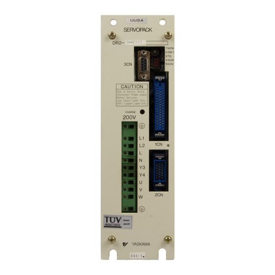
Page 176: Connector Terminal Layouts
3.8 Special Wiring 3.8.8 Connector Terminal Layouts This section describes connector terminal layouts for Servopacks, Servomotors and Digital Operator. 1) Servopack Connectors for Speed/Torque and Position Control 1CN Terminal Layout Open Collector Refer- Open Collector Refer- Frame Ground Frame Ground ence Power Supply Speed Monitor *PSO... - Page 177 APPLICATIONS OF Σ-SERIES PRODUCTS 3.8.8 Connector Terminal Layouts cont. 2CN Terminal Layout ⋅For Incremental Encoder PG0V PG0V PG0V PG0V PG0V PG0V PG5V PG5V PG5V PG5V PG5V PG5V ⋅For 12-bit Absolute Encoder PG0V PG0V PG0V PG0V PG0V PG0V RESET RESET PG5V PG5V PG5V PG5V...
- Page 178 3.8 Special Wiring 2) Connectors for Incremental Encoder Channel A output Blue Channel A output Blue/Black Channel B output Yellow Channel B output Yellow/Black Channel C output Green Channel C output Green/Black 0 V (power supply) Gray +5 V (power supply) Frame ground (FG) Orange Items to be Prepared by Customer...
- Page 179 APPLICATIONS OF Σ-SERIES PRODUCTS 3.8.8 Connector Terminal Layouts cont. 3) Connectors for Absolute Encoder Channel A output Blue Channel A output White/Blue Channel B output Yellow Channel B output White/Yellow Channel Z output Green Channel Z output White/Green 0 V (power supply) Black Do not use this termi- nal.
- Page 180 Brake terminal Black Cap: 172160-1 Socket: 170362-1 or 170366-1 (Manufactured by AMP) (DC side) AC input Black Brake power supply (manufactured by Yaskawa Controls Co., Ltd.) • 100 VAC input: 90 VDC (LPDE-1H01) • 200 VAC input: 90 VDC (LPSE-2H01)
- Page 181 APPLICATIONS OF Σ-SERIES PRODUCTS 3.8.8 Connector Terminal Layouts cont. 6) Connectors for Digital Operator • JUSP-OP02A-1 (Hand-held Type) 17JE-23090-02 Cable (manufactured by Daiichi (Provided) Denshi Kogyo K.K.) Pin Signal Signal Circuit Name Signal No. Name Direction Transmit data (non-inversion side) P z S Transmit data (inversion side) P z S Receive data (non-inversion side) P ! S...
-
Page 182: Using The Digital Operator
USING THE DIGITAL OPERATOR This chapter describes the basic operation of the digital operator and the con- venient features it offers. All constant settings and motor operations are possible by simple, conve- nient, operation. Operate the digital operator as you read through this chapter. 4.1 Basic Operations . -
Page 183: Basic Operations
USING THE DIGITAL OPERATOR 4.1.1 Connecting the Digital Operator Basic Operations This section describes the basic operations using the Digital Operator. 4.1.1 Connecting the Digital Operator ........4.1.2 Resetting Servo Alarms . -
Page 184: Resetting Servo Alarms
4.1 Basic Operations 4.1.2 Resetting Servo Alarms Servo alarms can be reset using the Digital Operator. (Servo alarms can also be reset by the 1CN-44, ALMRST input signal. Refer to 3.7.1 for details.) Alarm Reset Press NOTE After an alarm occurs, remove the cause of the alarm before resetting it. Refer to Section 6.2 Troubleshooting to determine and remedy the cause of an alarm. -
Page 185: Basic Functions And Mode Selection
USING THE DIGITAL OPERATOR 4.1.3 Basic Functions and Mode Selection 4.1.3 Basic Functions and Mode Selection Digital Operator operation allows status display, user constant setting, operating reference, and auto-tuning operations. Basic Mode Selection The four basic modes are listed below. Each time the mode key is pressed, the next mode in the sequence is selected. -
Page 186: Operation In Status Display Mode
4.1 Basic Operations 4.1.4 Operation in Status Display Mode The status display mode displays the Servopack status as bit data and codes. • Selecting Status Display Mode Press to select the status display mode. The status display mode is selected when the Status Display power supply is turned ON. - Page 187 USING THE DIGITAL OPERATOR 4.1.4 Operation in Status Display Mode cont. Bit Data Description Control Power ON Lit when Servopack control power ON. Not lit when Servopack control power OFF. Main Power ON Lit when Servopack main circuit power ON. Not lit when Servopack main circuit power OFF.
- Page 188 4.1 Basic Operations For Position Control Bit Data Code Positions Positioning Complete Base Block Control Power ON see next page TGON or Brake Interlock Signal Reference Pulse Input see below Main Power ON CLR Input Code Status Base block Servo OFF Servo ON Forward Rotation Prohibited 1CN-42 (P-OT) OFF.
-
Page 189: Operation In User Constant Setting Mode
USING THE DIGITAL OPERATOR 4.1.5 Operation in User Constant Setting Mode Bit Data Description Control Power ON Lit when Servopack control power ON. Not lit when Servopack control power OFF. Main Power ON Lit when Servopack main circuit power ON. Not lit when Servopack main circuit power OFF. - Page 190 4.1 Basic Operations 2) Using the Setting Mode for Constant Settings (Cn-03 to Cn-23) The constant settings (Cn-03 to Cn-23) allow setting of a constant. Check the permitted range of the constant in Appendix D List of User Constant Settings, before changing the data.
- Page 191 USING THE DIGITAL OPERATOR 4.1.5 Operation in User Constant Setting Mode cont. 3) Using the Setting Mode for Memory Switches (Cn-01, Cn-02) Turn the bits of the memory switches ON and OFF to select the functions required. The example below shows how to turn ON Bit 4 of memory switch Cn-01. 1) Press DSPL to select the user constant...
-
Page 192: Operation In Monitor Mode
4.1 Basic Operations DATA Memory 8) Press once more to display the user User Constant ENTER Switch Data Number constant number again. • Refer to Appendix D List of User Constant Settings. 4.1.6 Operation in Monitor Mode 1) The monitor mode allows the reference values input into the Servopack, I/O signal status, and Servopack internal status to be monitored. - Page 193 USING THE DIGITAL OPERATOR 4.1.6 Operation in Monitor Mode cont. 3) Keys to Monitor Mode Display are shown below. Note that the display differs between the speed/torque control and position control types. For Speed/Torque Control Monitor Monitor Display Speed/Torque Number Actual motor speed Units: r/min Input speed reference...
- Page 194 4.1 Basic Operations For Position Control Monitor Monitor Display Positions Number Actual motor speed Units: r/min Internal torque reference Units: % (with respect to rated torque) Number of pulses from motor U-phase edge Units: pulses Internal Status Electrical angle Bit Display Units: 0.1deg Internal status bit display Internal status bit display...
- Page 195 USING THE DIGITAL OPERATOR 4.1.6 Operation in Monitor Mode cont. Monitor Bit # Description Related I/O Signal, User Constant Un-06 Input reference pulse 1CN-1 (PLUS), 1CN-2( PULS) £ Input pulse sign 1CN-3(SIGN), 1CN-4 ( SIGN) £ Error counter clear input 1CN-5 (CLR), 1CN-6( CLR) £...
-
Page 196: Using The Functions
4.2 Using the Functions Using the Functions This section describes how to use the basic operations described in section 1 to operate and adjust the motor. 4.2.1 Operation in Alarm Trace-back Mode ....... 4.2.2 Operation Using the Digital Operator . - Page 197 USING THE DIGITAL OPERATOR 4.2.1 Operation in Alarm Trace-back Mode cont. 2) Using the Alarm Trace-back Mode Follow the procedure below to determine which alarms occurred previously. 1) Press DSPL to select the alarm trace- back mode. Alarm Trace-back Mode 2) Press the keys to scroll the Older...
-
Page 198: Using The Functions
4.2 Using the Functions 3) The table below lists the alarms displayed in the alarm trace-back mode. Displayed Alarm Description Code Absolute data error User constant breakdown User constant setting error Overcurrent Blown fuse Regenerative error Position error pulse overflow (for position control only) Overvoltage Overspeed Overload... -
Page 199: Operation Using The Digital Operator
USING THE DIGITAL OPERATOR 4.2.2 Operation Using the Digital Operator The following are operator-related alarms which are not recorded by alarm trace-back. Digital Operator transmission error 1 Digital Operator transmission error 2 • Refer to the troubleshooting procedures when an alarm occurs, described in section 6.2. - Page 200 4.2 Using the Functions 2) Select the user constant number Cn-00. Select Cn-00. (User constant Cn-00 is selected when the power is turned ON.) The selected digit blinks. Press the keys to select the digit. Press the keys to change the value. DATA 3) Press to display the current data for...
-
Page 201: Autotuning
USING THE DIGITAL OPERATOR 4.2.3 Autotuning 2) Changing Motor Speed The motor speed for operation under Digital Operator control can be changed with a fol- lowing user constant. JOGSPD Jog Speed Unit: r/min Setting Factory For Speed/ Range: Setting: Torque Cn-10 0 to MAX. - Page 202 4.2 Using the Functions 3) User Constants Automatically Settable with Autotuning Speed/torque Position control Speed/Torque control Positions Cn-04 Speed loop gain Cn-04 Speed loop gain Cn-05 Speed loop integration time Cn-05 Speed loop integration time constant constant Cn-1A Position loop gain Once autotuning has been completed, the autotuning procedure can be omitted for sub- sequent machines, providing the machine specifications remain unchanged.
- Page 203 USING THE DIGITAL OPERATOR 4.2.3 Autotuning cont. Operating Level User Constant Setting Torque reference Cn-0C to maximum torque Speed reference Cn-0D to a preset value exceeding Cn-10 Acceleration Cn-0E to the maximum value: 3000 Error pulse Cn-0F to the maximum value: 10000 Select the operating level using Bit C and Bit D of Cn-01.
- Page 204 4.2 Using the Functions 4) Using Autotuning Follow the procedure below to run autotuning. 1) Press DSPL to select the user constant setting mode. Setting Mode 2) Select the user constant number Cn-00. Select Cn-00. (User constant Cn-00 is selected when the power is turned ON.) The selected digit blinks.
- Page 205 USING THE DIGITAL OPERATOR 4.2.3 Autotuning cont. 8) Press to set the servo ON status. Press SVON Servo ON - motor ON Select Servo ON/Servo OFF Servo OFF to change. - base block 9) Press the keys to operate the Motor runs Motor forward while...
- Page 206 4.2 Using the Functions • If the Machine Resonates At servo ON when the key is pressed or when the motor is operated by press- SVON ing the key, machine resonance indicates an inappropriate machine rigid- ity setting. Follow the procedure below to correct the machine rigidity setting, and run autotuning once more.
- Page 207 USING THE DIGITAL OPERATOR 4.2.3 Autotuning cont. c) Input Signals • The OT signal and SEN signal (absolute encoder only) are enabled during autotuning. Input the OT signal and SEN signal (absolute encoder only) during autotuning. To conduct autotuning without inputting these signals, set user constant Cn-01 Bits 1, 2, and 3 to 1.
-
Page 208: Reference Offset Automatic Adjustment
4.2 Using the Functions 4.2.4 Reference Offset Automatic Adjustment 1) Why Does Reference Offset Occur? Using a speed/torque control, the motor may rotate slowly when the reference voltage is intended to be 0 V. Speed/Torque This occurs when the host controller or external circuit has a small offset (measured in mV) in the reference voltage. - Page 209 USING THE DIGITAL OPERATOR 4.2.4 Reference Offset Automatic Adjustment cont. 3) Using the Reference Offset Automatic Adjustment Mode Follow the procedure below to automatically adjust the reference offset. 1) Follow the procedure below to set the mo- Motor 0 V Speed tor into operating mode.
-
Page 210: Speed Reference Offset Manual Adjustment Mode
4.2 Using the Functions 4) The reference offset automatic adjustment mode cannot be used where a position loop is formed with the host controller and the error pulses are zeroed when servo lock is stopped. In this case, use the speed reference offset manual adjustment mode. Refer to sub-sec- tion 4.2.5 for details. - Page 211 USING THE DIGITAL OPERATOR 4.2.5 Speed Reference Offset Manual Adjustment Mode cont. Offset Adjustment Range and Setting Units are as follows: Reference Speed or Reference Torque Offset Adjustment Range Speed Reference Input Voltage Offset Units or Torque Reference Input Voltage Offset Adjustment Range: -512 to +511 (78 mV) Offset Units: Reference Speed: 0.038 r/min.
- Page 212 4.2 Using the Functions 4) Press the keys to change the Set to 00-03. data to 03. Press the keys to change the value. 5) Press DSPL to select the speed refer- ence offset manual adjustment mode. Speed Reference (The amount of speed reference offset is Offset Manual Adjustment Mode displayed.)
-
Page 213: Clearing Alarm Trace-Back Data
USING THE DIGITAL OPERATOR 4.2.6 Clearing Alarm Trace-back Data 4.2.6 Clearing Alarm Trace-back Data 1) This procedure clears the alarm history, which stores the alarms occurring in the Servo- pack. Each alarm in the alarm history is set to A99, which is not an alarm code. Refer to 4.2.1 Operation in Alarm Trace-back Mode for details. -
Page 214: Checking Motor Type
4.2 Using the Functions 4.2.7 Checking Motor Type 1) Set Cn-00 to 00-04 to select the motor-type check mode. This mode is used for maintenance and is not normally used by the customer. Operation Motor Type Display Set Cn-00 to 00-04 Motor Capacity 9E: 30W Motor Type... -
Page 215: Chapter 5 Servo Selection And Data Sheets
SERVO SELECTION AND DATA SHEETS This chapter describes how to select Σ-Series servo drives and peripheral de- vices. The section also presents the specifications and dimensional drawings re- quired for selection and design. Choose and carefully read the relevant sections of this chapter. 5.1 Selecting a Σ-Series Servo . - Page 216 Chapter Table of Contents, Continued 5.6 Specifications and Dimensional Drawings of Peripheral Devices ..... . 5.6.1 Cable Specifications and Peripheral Devices .
-
Page 217: Selecting A Σ-Series Servo
5.1 Selecting a Σ -Series Servo Selecting a Σ-Series Servo This section describes how to select the Σ-Series Servomotor, Servopack, and Digital Operator. 5.1.1 Selecting a Servomotor ......... . . 5.1.2 Selecting a Servopack . - Page 218 SERVO SELECTION AND DATA SHEETS 5.1.1 Selecting a Servomotor cont. SGM- 01 3 1 2 j Σ-Series SGM: SGM Servomotor SGMP: SGMP Servomotor (cube type) 1) Rated output (motor capacity) (Type SGM only) A3: 30W (0.04HP) A5: 50W (0.07HP) (Types SGM and SGMP) 01: 100W (0.13HP) 02: 200W (0.27HP) 03: 300W (0.40HP) 04: 400W (0.53HP) 08: 750W (1.01HP)
- Page 219 5.1 Selecting a Σ -Series Servo 2) The actual selection of the SGM or SGMP Servomotor is conducted according to the flowchart in the next page. If an SGMP Servomotor is selected, replace SGM with SGMP. SGMP Servomotors are available from 100W (0.13HP) to 750W (1.01HP). A 1500W (2.01HP) type also exists but the DR2 Servopack can handle up to 750W (1.01HP).
- Page 220 SERVO SELECTION AND DATA SHEETS 5.1.1 Selecting a Servomotor cont. Flowchart for Servomotor Selection Start Servomotor selection If necessary, refer to the data sheets in 5.2.1 1) Select motor capacity D D D Ratings and Specifications. Refer to 3) Machine Data Table on page 210. Fill in Machine Data Table D D D Select capacity using...
- Page 221 Under gravitational load SGM-jjjjjjB With shaft seal Oil used at end of shaft SGM-jjjjjjS With brake and Gravitational load+oil shaft seal SGM-jjjjjjD Drip-proofed Subject to water droplets SGM-jjjjjjP End Servomotor selection Note Consult Yaskawa sales representative for sizing or sizing software.
- Page 222 SERVO SELECTION AND DATA SHEETS 5.1.1 Selecting a Servomotor cont. 3) Machine Data Table Fill out the machine data table below as an aid to selecting the drive system. When the machine data table is complete, use the servomotor sizing software to select the motor capacity.
- Page 223 5.1 Selecting a Σ -Series Servo 5) Roll Feeder Press force Load GD kg¡cm (lb¡in ℓ Tension kg (lb) Press force kg (lb) Roller Roller diameter mm (in.) Coefficient of friction µ Motor Motor Overall efficiency η Gear+coupling Gear+coupling Gear ratio R (= Nm/Nl) Gear+coupling kg¡cm...
-
Page 224: Selecting A Servopack
SERVO SELECTION AND DATA SHEETS 5.1.2 Selecting a Servopack 5.1.2 Selecting a Servopack 1) The selection of a DR2 Servopack matched to the servo system in which it is used is based on the Servopack type, that is, the four to six alphanumeric characters after “DR2-”, described below. - Page 225 5.1 Selecting a Σ -Series Servo DR2 - 01 A C P - F Σ-Series DR2: DR2 Servopack 1) Rated output A3: 30W (0.04HP) A5: 50W (0.07HP) 01: 100W (0.13HP) 02: 200W (0.27HP) 03: 300W (0.40HP) 04: 400W (0.53HP) 08: 750W (1.01HP) 2) Supply voltage A: 200V B: 100V 3) Model...
- Page 226 SERVO SELECTION AND DATA SHEETS 5.1.2 Selecting a Servopack cont. 2) The actual selection of the DR2 Servopack is conducted according to the following flow- chart. Flowchart for Servopack Selection Start Servopack selection Check specifications in 5.3.1 Ratings 1) Enter rated output D D D and Specifications.
- Page 227 5.1 Selecting a Σ -Series Servo From the previous page 5) Determine option specifications Semi-closed specifications (standard) DR2-jjjjj Semi-closed/Full-closed? Full-closed specifications DR2-jjjjj-F End Servopack selection...
-
Page 228: Digital Operator
SERVO SELECTION AND DATA SHEETS 5.1.3 Digital Operator 5.1.3 Digital Operator 1) Use the following digital operator (hand-held type) for operation. • Use held in the hand while connected with the 1 m cable supplied. JUSP-OP02A-1 (Hand-held Type) Note Mount type digital operator (JUSP-OP03A) cannot be used for DR2 Servopack. -
Page 229: Sgm Servomotor
5.2 SGM Servomotor SGM Servomotor This section presents tables of ratings and specifications for SGM and SGMP Servomotors. Refer to these tables when selecting a Servomotor. 5.2.1 Ratings and Specifications ........5.2.2 Mechanical Characteristics . - Page 230 SERVO SELECTION AND DATA SHEETS 5.2.1 Ratings and Specifications cont. SGM Servomotor Rated Output* W (HP) (0.04) (0.07) (0.13) (0.27) (0.53) (1.01) Rated Torque* N¡m 0.095 0.159 0.318 0.637 1.27 2.39 (oz¡in) (13.5) (22.6) (45.1) (90.1) (181) (338) Instantaneous Peak Torque* N¡m 0.29 0.48...
- Page 231 5.2 SGM Servomotor Type SGM− Item −4 Holding brake kg¡m 0.0085 0.058 0.14 ¢10 −3 (oz¡in¡s (0.120) (0.816) (1.98) ¢10 −4 12-bit absolute kg¡m 0.025 ¢10 encoder −3 (oz¡in¡s (0.352) ¢10 Electrical Specifications of the Holding Brake a) SGM Type (Rated Voltage: 90 VDC) Standard Motor Model Motor...
- Page 232 SERVO SELECTION AND DATA SHEETS 5.2.1 Ratings and Specifications cont. 3) 200-VAC SGM Servomotor Torque-Motor Speed Characteristics • SGM-A3A (V) • SGM-A5A (V) 4000 4000 3000 3000 Motor Motor Speed Speed (r/min) (r/min) 2000 2000 1000 1000 0.15 0.45 • SGM-01A (V) •...
- Page 233 5.2 SGM Servomotor 4) Ratings and Specifications of 200-VAC SGMP Servomotors Time rating: continuous Heat resistance class: Class B (Class A for UL spec. type SGMP-jU) Vibration class: 15µm or below Withstand voltage: 1500 VAC Insulation resistance: 500 VDC 10MΩ min. Enclosure: totally enclosed, self-cooled Ambient temperature:...
- Page 234 SERVO SELECTION AND DATA SHEETS 5.2.1 Ratings and Specifications cont. Rated torques are continuous allowable torque values at 40°C with an attached heat sink as specified below. Heat sink dimensions 01A, 02A, 04A 250¢250¢6(mm), (9.84¢9.84¢0.24 (in.)) ..300¢300¢12(mm),(11.81¢11.81¢0.47(in.)) Electrical Specifications of the Holding Brake a) SGMP Type (Rated Voltage: 90 VDC)
- Page 235 5.2 SGM Servomotor 5) 200-VAC SGMP Servomotor Torque-Motor Speed Characteristics • SGMP-01A (V) • SGMP-02A (V) 4000 4000 3000 3000 Motor Motor Speed Speed (r/min) (r/min) 2000 2000 1000 1000 • SGMP-04A (V) • SGMP-08A (V) 4000 4000 3000 3000 Motor Motor Speed...
- Page 236 SERVO SELECTION AND DATA SHEETS 5.2.1 Ratings and Specifications cont. 6) Ratings and Specifications of 100-VAC SGM Servomotors Time rating: continuous Heat resistance class: Class B (Class A for UL spec. type SGM-jU) Vibration class: 15µm or below Withstand voltage: 1500 VAC Insulation resistance: 500 VDC 10MΩ...
- Page 237 5.2 SGM Servomotor NOTE The ratings and specifications above refer to a standard Servomotor. Add the numerical values below to the moment of inertia values in the table for a motor fitted with a holding brake and/or a 12-bit absolute encoder. Other specifications will also change slightly.
- Page 238 SERVO SELECTION AND DATA SHEETS 5.2.1 Ratings and Specifications cont. 7) 100-VAC SGM Servomotor Torque-Motor Speed Characteristics • SGM-A3B (W) • SGM-A5B (W) 4000 4000 3000 3000 Motor Motor Speed Speed 2000 2000 (r/min) (r/min) 1000 1000 0.15 0.3 0.45 •...
- Page 239 5.2 SGM Servomotor 8) Ratings and Specifications of 100-VAC SGMP Servomotors Time rating: continuous Heat resistance class: Class B (Class A for UL spec. type SGMP-jU) Vibration class: 15µm or below Withstand voltage: 1500 VAC Insulation resistance: 500 VDC 10MΩ min. Enclosure: totally enclosed, self-cooled Ambient temperature:...
- Page 240 SERVO SELECTION AND DATA SHEETS 5.2.1 Ratings and Specifications cont. Electrical Specifications of the Holding Brake a) SGMP Type (Rated Voltage: 90 VDC) ..Standard Motor Model Motor Holding Brake Specifications Capacity Capacity Holding Coil Rated...
- Page 241 5.2 SGM Servomotor 9) 100-VAC SGMP Servomotor Torque-Motor Speed Characteristics • SGMP-01B (W) • SGMP-02B (W) 4000 4000 3000 3000 Motor Motor Speed Speed 2000 (r/min) 2000 (r/min) 1000 1000 • SGMP-03B (W) 4000 3000 Motor Speed 2000 (r/min) 1000 A: Continuous Duty Zone B: Intermittent Duty Zone...
-
Page 242: Mechanical Characteristics
Conduct mechanical design such that the thrust loads and radial loads do not exceed the values stated below. Servomotor Allowable Allowable Reference Diagram Type Radial Load Thrust Load Fr [N(lb)] Fs [N(lb)] (in.) SGM-A3 68 (15) 54 (12) 20 (0.82) SGM-A5 68 (15) 54 (12) 20 (0.82) SGM-01 78 (17) 54 (12) 20 (0.82) - Page 243 5.2 SGM Servomotor 2) Mechanical Tolerance The tolerances of the SGM and SGMP Servomotor output shaft and installation are shown in the table below. Tolerance (T.I.R.) Reference Diagram Perpendicularity between flange 0.04mm face and output shaft (0.0016in.) Mating concentricity of flange O.D. 0.04mm (0.0016in.) Run-out at end of shaft...
- Page 244 SERVO SELECTION AND DATA SHEETS 5.2.2 Mechanical Characteristics cont. 6) Vibration Class Vibration Measurement Position The SGM and SGMP Servomotors meet the following vibration class at rated speed. • Vibration Class: 15µm or below Vibration Class TERMS Vibration class 15µm or below indicates that the total amplitude of vibration of the motor alone, running at rated speed, does not exceed 15µm.
-
Page 245: Servopack Ratings And Specifications
5.3 Servopack Ratings and Specifications Servopack Ratings and Specifications This section presents tables of DR2 Servopack ratings and specifications separately for speed/torque control and for position control. 5.3.1 Ratings and Specifications ........5.3.2 Power Consumption . - Page 246 SERVO SELECTION AND DATA SHEETS 5.3.1 Ratings and Specifications cont. Voltage 200 VAC 100 VAC Servopack Type DR2- A3AC A5AC 01AC 02AC 04AC 08AC A3BC A5BC 01BC 02BC 03BC Max. Applicable Motor Capacity W (HP) (0.04) (0.07) (0.13) (0.27) (0.53) (1.01) (0.04) (0.07)
- Page 247 5.3 Servopack Ratings and Specifications Indicators Power (green LED) and status/alarm (red, 7-segment LEDs) Digital operator: status/alarm (red, 7-segment LEDs ×5) Others Torque control, zero clamp operation (position loop stop}, soft start/stop, speed coincidence, brake interlock signal output, reverse run connection, JOG run, auto-tuning Allowable load inertia ranges require no optional regenerative unit (applicable to 200V 30W to 200W) or external regenerative resistor (applicable to 100V 200W, 300W or 200V 400W, 750W).
- Page 248 SERVO SELECTION AND DATA SHEETS 5.3.1 Ratings and Specifications cont. 3) Ratings and Specifications of DR2 Servopack for Position Control Voltage 200 VAC 100 VAC Servopack Type DR2- A3AC A5AC 01AC 02AC 04AC 08AC A3BC A5BC 01BC 02BC 03BC Max. Applicable Motor Capacity W (HP) (0.04) (0.07)
- Page 249 5.3 Servopack Ratings and Specifications Overtravel Dynamic brake stop at P-OT or N-OT or deceleration stop Protective Functions Overcurrent, overload, overvoltage, overspeed, overrun prevention, origin error, CPU error, encoder error, overflow, fuse blown, undervoltage Indicators Power (green LED) and status/alarm (red, 7-segment LEDs) Digital operator: status/alarm (red, 7-segment LEDs ×5) Others Brake interlock signal output, reverse run connection, JOG run, electronic gear, auto-tuning...
-
Page 250: Power Consumption
(300W-0.40HP) Note Power loss of regenerative resistor shows the allowable loss. If this value is exceeded, re- move the built-in regenerative resistor inside the Servopack and install a resistor externally. Before installing an external regenerative resistor, contact your Yaskawa representative. -
Page 251: Overload Characteristics
5.3 Servopack Ratings and Specifications 5.3.3 Overload Characteristics The Servopack has a built-in overload protective function to protect the Servopack and Ser- vomotor from overload. Therefore, the Servopack allowable power is limited by the overload protective function, as shown below. The overload detection level is quoted under hot start conditions at a motor ambient temper- ature of 40°C. -
Page 252: Starting Time And Stopping Time
SERVO SELECTION AND DATA SHEETS 5.3.4 Starting Time and Stopping Time 5.3.4 Starting Time and Stopping Time 1) The motor starting time (tr) and stopping time (tf) under constant load are calculated by the following formulas. The motor viscous torque and friction torque are ignored. Starting Time: tf = 104.7 ×... -
Page 253: Load Inertia
5.3 Servopack Ratings and Specifications 5.3.5 Load Inertia 1) The larger the load inertia becomes, the worse the movement response of the load. The size of the load inertia [J ] allowable when using a Servomotor depends on the motor capacity, as shown in the diagrams below. - Page 254 SERVO SELECTION AND DATA SHEETS 5.3.5 Load Inertia cont. a) SGM Servomotors 200-VAC Servomotors with incremental encoder Load Inertia Load Inertia −4 −4 kg¡m kg¡m ¢10 ¢10 −3 −3 (oz¡in¡s (oz¡in¡s ¢10 ¢10 (0.27HP) (0.04HP) 0.63 (51.2) (8.92) 2.83 ( 40.1 ) Motor Speed Motor Speed Load Inertia...
- Page 255 5.3 Servopack Ratings and Specifications b) SGM Servomotors 100-VAC Servomotors with incremental encoder Load Inertia Load Inertia −4 −4 kg¡m kg¡m ¢10 ¢10 −3 −3 (oz¡in¡s (oz¡in¡s ¢10 ¢10 200W 3.69 (0.04HP) (0.27HP) (52.3 ) 0.63 (8.21) 3000 4500 Motor Speed Motor Speed Load Inertia Load Inertia...
- Page 256 SERVO SELECTION AND DATA SHEETS 5.3.5 Load Inertia cont. c) SGMP Servomotors 200-VAC Servomotors with incremental encoder Load Inertia Load Inertia −4 −4 kg¡m kg¡m ¢10 ¢10 −3 −3 (oz¡in¡s (oz¡in¡s ¢10 ¢10 200W (0.13HP) (0.27HP) 1.95 6.27 (88.8 ) (27.6) 2.65 (37.5 )
- Page 257 5.3 Servopack Ratings and Specifications d) SGMP Servomotors 100-VAC Servomotors with incremental encoder Load Inertia Load Inertia −4 −4 kg¡m kg¡m ¢10 ¢10 −3 −3 (oz¡in¡s (oz¡in¡s ¢10 ¢10 200W (0.13HP) (0.27HP) 6.27 1.95 (88.8 ) (27.6 ) 4500 3000 Motor Speed Motor Speed Load Inertia...
-
Page 258: Overhanging Loads
SERVO SELECTION AND DATA SHEETS 5.3.6 Overhanging Loads 2) An overvoltage alarm is likely during deceleration if the load inertia exceeds the range of the diagrams. Take one of the countermeasures below. a) Reduce the torque limit value. b) Reduce the deceleration rate. c) Reduce the maximum speed used. -
Page 259: Σ-Series Dimensional Drawings
5.4 Σ-Series Dimensional Drawings Σ-Series Dimensional Drawings This section presents dimensional drawings of the Σ-Series Servomotor, Servopack, and Digital Operator. 5.4.1 Servomotor Dimensional Drawings ....... . . 5.4.2 Servomotor Dimensional Drawings (TÜV approved, conforming to the machine instructions) - Page 260 SERVO SELECTION AND DATA SHEETS 5.4.1 Servomotor Dimensional Drawings cont. (1) SGM Servomotor Incremental encoder, no brake (Type SGM-jjj31j) • 30W (0.04 HP), 50W (0.07 HP),100W (0.13 HP) 300 30 (11.811.18) 35 (1.38) Encoder Plug Encoder Lead UL2854 Motor Lead UL1828 or UL3534 Protective Tube (Black) Motor Plug...
- Page 261 5.4 Σ-Series Dimensional Drawings Note 1) The detector uses an incremental encoder 2048 P/R. 2) Type “A” indicates 200 V specification, and type “B” indicates 100 V specification. 3) “A3A(B)314”, “A3A(B)316”, “A5A(B)314”, “A5A(B)316” “01A(B)314” and “01A(B)316” have a keyed shaft. The keyway complies with JIS B 1301-1976 (precision). A straight key is supplied.
- Page 262 SERVO SELECTION AND DATA SHEETS 5.4.1 Servomotor Dimensional Drawings cont. Type Screw Approx. Allow- Allow- SGM- dimensions mass able able radial thrust (HP) (lb) load load N (lb) N (lb) 02A312 126.5 96.5 62.5 No key − 02B312 (4.98) (3.80) (2.46) ( 98) (3 80) (2 6)
- Page 263 5.4 Σ-Series Dimensional Drawings • 750 W (1.01 HP) Encoder Lead Encoder Plug Screw Motor Lead (Teflon wire) AWG20 UL1828 or UL3534 Motor Plug Protective Tube (Black) Cross-section Y-Y 80 (3.15) φ 90 ( φ 3.54) 4-φ7 (φ0.28) MTG Holes 4−R8.2 Shaft end screw hole (SGM-...
- Page 264 SERVO SELECTION AND DATA SHEETS 5.4.1 Servomotor Dimensional Drawings cont. • Details of Motor and Encoder Plugs (Common for 30 W (0.04 HP) to 750 W (1.01 HP) Motor Plug Motor Wiring Specifications Plug : 172167-1 (AMP) U phase Pin: 170360-1 or 170364-1 V phase White (170359-1 or 170363-1: 30, 50, or...
- Page 265 5.4 Σ-Series Dimensional Drawings (2) SGM Servomotor Incremental encoder, with brake (Type SGM-jjj31jB) • 30W (0.04 HP), 50W (0.07 HP), 100W (0.13 HP) 30030 (11.811.18) Encoder Lead Encoder Plug 35 (1.38) Motor Lead UL1828 or UL3534 Motor Plug Protective Tube (0.0008) (0.0016) (Black)
- Page 266 SERVO SELECTION AND DATA SHEETS 5.4.1 Servomotor Dimensional Drawings cont. Note 1) The detector uses an incremental encoder 2048 P/R. 2) Type “A” indicates 200 V specification, and type “B” indicates 100 V specification. 3) “A3A(B)314B”, “A3A(B)316B”, “A5A(B)314B”, “A5A(B)316B”, “01A(B)314B” and “01A(B)316B”...
- Page 267 5.4 Σ-Series Dimensional Drawings Type Screw Out- Approx. Allow- Allow- SGM- dimensions mass able able radial thrust (HP) (lb) load load N (lb) N (lb) 02A312B 166.0 136.0 62.5 No key − 02B312B (6.54) (5.35) (2.46) ( 3 ) (2 6) (0 2 ) (0.27) (3 3)
- Page 268 SERVO SELECTION AND DATA SHEETS 5.4.1 Servomotor Dimensional Drawings cont. • 750 W (1.01 HP) Encoder Lead Encoder Plug Screw Motor Lead (Teflon wire) AWG22 Motor Plug UL1828 or UL3534 Protective Tube (Black) Cross-section Y-Y 34 (1.34) 111 (4.37) 15 (0.59) 80 (3.15) Brake φ90...
- Page 269 5.4 Σ-Series Dimensional Drawings • Details of Motor and Encoder Plugs (Common for 30 W (0.04 HP) to 750 W (1.01 HP) Motor Plug Motor Wiring Specifications Plug : 172168-1 (AMP) Pin: 170360-1 or 170364-1 U phase (17359-1 or 170363-1: 30, 50, or V phase White 100 W only)
- Page 270 SERVO SELECTION AND DATA SHEETS 5.4.1 Servomotor Dimensional Drawings cont. (3) SGM Servomotor Absolute encoder, no brake (Type SGM-jjjW1j) • 30 W (0.04 HP), 50 W (0.07 HP), 100 W (0.13 HP) 30030 (11.811.18) Encoder Lead UL20276 Encoder Plug 35 (1.38) Motor Lead (Teflon wire) AWG24 Screw UL1828 or UL3534...
- Page 271 5.4 Σ-Series Dimensional Drawings Note 1) The detector uses a 12-bit absolute encoder 1024 P/R. 2) Type “A” indicates 200 V specification, and type “B” indicates 100 V specification. 3) “A3A(B)W14”, “A3A(B)W16”, “A5A(B)W14”, “A5A(B)W16”, “01A(B)W14” “01A(B)W16” have a keyed shaft. The keyway complies with JIS B 1301-1976 (preci- sion).
- Page 272 SERVO SELECTION AND DATA SHEETS 5.4.1 Servomotor Dimensional Drawings cont. • 200 W (0.27 HP), 300W (0.40 HP), 400 W (0.53 HP) Encoder Lead 30030 (11.811.18) UL20276 35 (1.38) Encoder Plug Screw Motor Lead (Teflon wire) AWG24 UL1828 or UL3534 Motor Plug Protective Tube (Black) Cross-section Y-Y...
- Page 273 5.4 Σ-Series Dimensional Drawings Note 1) The detector uses a 12-bit absolute encoder 1024 P/R. 2) Type “A” indicates 200 V specification, and type “B” indicates 100 V specification. 3) “02A(B)W14”, “02A(B)W16”, “03BW14” “03BW16”, “04AW14” and “04AW16” have a keyed shaft. The keyway complies with JIS B 1301-1976 (precision). A straight key is supplied.
- Page 274 SERVO SELECTION AND DATA SHEETS 5.4.1 Servomotor Dimensional Drawings cont. • 750 W (1.01 HP) Encoder Lead 30030 (11.811.18) UL20276 35 (1.38) Encoder Plug Screw Motor Lead UL1828 or UL3534 Motor Plug Protective Tube (Black) 30030 (11.811.18) (0.0016) Cross-section Y-Y 0.04 206 (8.10) 166 (6.54)
- Page 275 5.4 Σ-Series Dimensional Drawings • Details of Motor and Encoder Plugs (Common for 30 W (0.04 HP) to 750 W (1.01 HP) Motor Plug Motor Wiring Specifications Plug : 172167-1 (AMP) U phase Pin: 170360-1 or 170364-1 V phase White (17359-1 or 170363-1: 30, 50, or 100 W only) W phase...
- Page 276 SERVO SELECTION AND DATA SHEETS 5.4.1 Servomotor Dimensional Drawings cont. (4) SGM Servomotor Absolute encoder, with brake (Type SGM-jjjW1jB) • 30 W (0.04 HP), 50 W (0.07 HP), 100 W (0.13 HP) Encoder Lead 30030 (11.811.18) UL20276 35 (1.38) Screw Encoder Plug Motor Lead (Teflon wire) AWG24 UL1828 or UL3534...
- Page 277 5.4 Σ-Series Dimensional Drawings Note 1) The detector uses a 12-bit absolute encoder 1024 P/R. 2) Type “A” indicates 200 V specification, and type “B” indicates 100 V specification. 3) “A3A(B)W14B”, “A3A(B)W16B”, “A5A(B)W14B”, “A5A(B)W16B”, “01A(B)W14B” and “01A(B)W16B” have a keyed shaft. The keyway complies with JIS B 1301-1976 (preci- sion).
- Page 278 SERVO SELECTION AND DATA SHEETS 5.4.1 Servomotor Dimensional Drawings cont. Type Screw Out- Approx. Allow- Allow- SGM- dimen- mass able able sions radial thrust (HP) load load (lb) N (lb) N (lb) (HP) 02AW12B 187.0 157.0 62.5 No key − ( 36) (7.36) (6.18) (2.46) (6 18)
- Page 279 5.4 Σ-Series Dimensional Drawings • 750 W (1.01 HP) 30030 (11.811.18) 35 (1.38) Encoder Plug Screw Motor Lead UL1828 or UL3534 Protective Tube (Black) Motor Plug Encoder Lead 30030 (11.811.18) UL20276 Cross-section Y-Y (0.0016) 0.04 250.5 (9.86) 40 (1.57) 210.5 (8.29) (0.0016) 55 (2.17) 111 (4.35)
- Page 280 SERVO SELECTION AND DATA SHEETS 5.4.1 Servomotor Dimensional Drawings cont. • Details of Motor and Encoder Plugs (Common for 30 W (0.04 HP) to 750 W (1.01 HP) Motor Wiring Specifications Motor Plug U phase Plug : 172168-1 (AMP) V phase White Pin: 170360-1 or 170364-1 W phase...
- Page 281 5.4 Σ-Series Dimensional Drawings 2) The dimensional drawings of the SGMP Servomotors are broadly grouped into the fol- lowing four categories. a) Incremental encoder, no brake (from page 270) b) Incremental encoder, with brake (from page 275) c) Absolute encoder, no brake (from page 280) d) Absolute encoder, with brake (from page 284) Motor capacities are available as 100 W (0.13 HP), 200 W (0.27 HP), 300 W (0.40 HP) , 400 W (0.53 HP), 750 W (1.01 HP).
- Page 282 SERVO SELECTION AND DATA SHEETS 5.4.1 Servomotor Dimensional Drawings cont. (1) SGMP Servomotor Incremental encoder, no brake (Type SGM-jjj31j) • 100 W (0.13 HP) Encoder Lead Encoder Plug UL2854 Motor Lead Motor Plug Screw Cross-section Y-Y Hex. Nut 14 (0.55) Sealant Incremental Encoder 4-∅5.5...
- Page 283 5.4 Σ-Series Dimensional Drawings Note 1) The detector uses an incremental encoder 2048 P/R. 2) Type “A” indicates 200 V specification, and type “B” indicates 100 V specification. 3) “01A(B)314” and “01A(B)316” have a keyed shaft. The keyway complies with JIS B 1301-1976 (precision).
- Page 284 SERVO SELECTION AND DATA SHEETS 5.4.1 Servomotor Dimensional Drawings cont. Type Screw Out- Approx. Allowable Allowable SGMP- mass radial thrust men- load load sions (HP) (lb) N (lb) N (lb) 02A312 92 48.1 No key 245 (55.1) 68 (15.3) 02B312 (3.62) (3 62) (2.44) (1 89)
- Page 285 5.4 Σ-Series Dimensional Drawings • 750 W (1.01 HP) Encoder Lead Encoder Plug Motor Lead Motor Plug Screw Cross-section Y-Y Hex.nut 17 (0.67) Sealant MTG Holes Shaft end screw hole (SGMP-08A316, Incremental Encoder with key type only) Type Screw Output Approx.
- Page 286 SERVO SELECTION AND DATA SHEETS 5.4.1 Servomotor Dimensional Drawings cont. • Details of Motor and Encoder Plugs (Common for 100 W (0.13HP) to 750 W (1.01HP)) Motor Wiring Specifications Motor Plug Plug : 172167-1 (AMP) U phase Pin: 170360-1 or 170364-1 V phase White Blue...
- Page 287 5.4 Σ-Series Dimensional Drawings (2) SGMP Servomotor Incremental encoder, with brake (Type SGMP-jjj31jB) • 100 W (0.13HP) Screw Encoder Lead Encoder Plug Motor Plug Cross-section Y-Y Motor Lead Hex. nut 14 (0.55) 21(0.83) Sealant Shaft end screw hole Incremental Encoder Holding Brake (deenergization 4-∅5.5 (SGMP-01A(B)316B,...
- Page 288 SERVO SELECTION AND DATA SHEETS 5.4.1 Servomotor Dimensional Drawings cont. 4) The quoted allowable radial load is the value at a position 20 mm (0.79in.) from the motor mounting surface. 5) The electromagnetic brake is only to hold the load in position and cannot be used to stop the motor.
- Page 289 5.4 Σ-Series Dimensional Drawings Type Screw Out- Approx. Allow- Allow- SGMP- dimen- mass able able sions radial thrust load load (HP) (lb) N (lb) N (lb) 02A312B 123.5 93.5 48.1 No key 02B312B (4.86) ( 86) (3 68) (3.68) (1 89) (1.89) (0 2 ) (0.27)
- Page 290 SERVO SELECTION AND DATA SHEETS 5.4.1 Servomotor Dimensional Drawings cont. • 750 W (1.01HP) Encoder Lead Encoder Plug Screw Motor Lead Motor Plug Cross-section Y-Y Hex. nut 17 (0.67) Sealant MTG Holes Holding Brake (deenergization operation) Shaft end screw hole Incremental Encoder (φ0.0016) (SGMP-08A316B, with key type only)
- Page 291 5.4 Σ-Series Dimensional Drawings 4) The quoted allowable radial load is the value at a position 35 mm (1.38 in.) from the mo- tor mounting surface. 5) The electromagnetic brake is only to hold the load in position and cannot be used to stop the motor.
- Page 292 SERVO SELECTION AND DATA SHEETS 5.4.1 Servomotor Dimensional Drawings cont. (3) SGMP Servomotor Absolute encoder, no brake (Type SGMP-jjjW1j) • 100 W (0.13HP) Encoder Plug Encoder Lead Motor Plug Screw Motor lead Cross-section Y-Y Hex. nut 14 (0.55) 55 (2.17) 21 (0.83) sealant 4-∅5.5...
- Page 293 5.4 Σ-Series Dimensional Drawings • 200 W (0.27 HP), 300 W (0.40 HP) (100 V only), 400 W (0.53HP) (200 V only) Encoder Plug Encoder Lead Motor Plug Screw Cross-section Y-Y Hex. nut 14 (0.55) 4-∅7 Shaft end screw hole Absolute encoder (4-∅0.28) (SGMP-jj...
- Page 294 SERVO SELECTION AND DATA SHEETS 5.4.1 Servomotor Dimensional Drawings cont. 3) “02A(B)W14”, “02A(B)W16”, “03BW14”, “03BW16”, “04AW14”, and “04AW16” have a keyed shaft. The keyway complies with JIS B 1301-1976 (precision). A straight key is supplied. 4) The quoted allowable radial load is the value at a position 25 mm (0.98 in.) from the mo- tor mounting surface.
- Page 295 5.4 Σ-Series Dimensional Drawings Note 1) The detector uses a 12-bit absolute encoder 1024 P/R. 2) Type “A” indicates 200 V specification. 3) “08AW14” and “08AW16” have a keyed shaft. The keyway complies with JIS B 1301-1976 (precision). A straight key is supplied. 4) The quoted allowable radial load is the value at a position 35 mm (1.38 in.) from the mo- tor mounting surface.
- Page 296 SERVO SELECTION AND DATA SHEETS 5.4.1 Servomotor Dimensional Drawings cont. (4) SGMP Servomotor Absolute encoder, with brake (Type SGMP-jjjW1jB) • 100 W (0.13 HP) Encoder Plug Encoder Lead Screw Motor Lead Motor Plug Cross-section Y-Y Hex. nut 14 (0.55) 55 (2.17) Sealant Sealant Absolute Encoder...
- Page 297 5.4 Σ-Series Dimensional Drawings Note 1) The detector uses a 12-bit absolute encoder 1024 P/R. 2) Type “A” indicates 200 V specification, and type “B” indicates 100 V specification. 3) “01A(B)W14B” and “01A(B)W16B” have a keyed shaft. The keyway complies with JIS B 1301-1976 (precision).
- Page 298 SERVO SELECTION AND DATA SHEETS 5.4.1 Servomotor Dimensional Drawings cont. • 200 W (0.27 HP), 300 W (0.40 HP), 400 W (0.53 HP) Encoder Lead UL20276 300¦30(11.81¦1.18) (35)(1.38) Encoder Plug Screw Motor Lead UL2464 Motor Plug Cross-section Y-Y (35)(1.38) 300¦30(11.81¦1.18) Sealant Hex.hut 14 (0.55)
- Page 299 5.4 Σ-Series Dimensional Drawings 3) “02A(B)W14B”, “02A(B)W16B”, “03BW14B”, “03BW16B”, “04AW14B” and “04AW16B” have a keyed shaft. The keyway complies with JIS B 1301-1976 (precision). A straight key is supplied. 4) The quoted allowable radial load is the value at a position 25 mm (0.98 in.) from the mo- tor mounting surface.
- Page 300 SERVO SELECTION AND DATA SHEETS 5.4.1 Servomotor Dimensional Drawings cont. Note 1) The detector uses a 12-bit absolute encoder 1024 P/R. 2) Type “A” indicates 200 V specification. 3) “08AW14B” and “08AW16B” have a keyed shaft. The keyway complies with JIS B 1301-1976 (precision).
-
Page 301: Servomotor Dimensional Drawings
• As for the dimensional drawings of TÜV approved SGMP servomotors, see from the page 309 on. All drawings conform to the machine instructions. As for the motor drawings conforming to the EMC instructions, encoder plug and its accessories are different. For details, con- tact your Yaskawa representative. - Page 302 SERVO SELECTION AND DATA SHEETS 5.4.2 Servomotor Dimensional Drawings cont. (1) TÜV approved (conforming to the machine instructions) SGM Servomotor Incremental encoder, no brake (Type SGM-jjj31j) • 30W (0.04 HP), 50W (0.07 HP),100W (0.13 HP) (11.81¦1.18) (1.38) Motor Lead Marked Wire φ7 (φ0.29) Encoder Lead UL2854...
- Page 303 5.4 Σ-Series Dimensional Drawings Note 1) The detector uses an incremental encoder 2048 P/R. 2) Type “V” indicates 200 V specification, and type “W” indicates 100 V specification. 3) “A3V(W)314”, “A3V(W)316”, “A5V(W)314”, “A5V(W)316”, “01V(W)314” “01V(W)316” have a keyed shaft. The keyway complies with JIS B 1301-1976 (preci- sion).
- Page 304 SERVO SELECTION AND DATA SHEETS 5.4.2 Servomotor Dimensional Drawings cont. Note 1) The detector uses an incremental encoder 2048 P/R. 2) Type “V” indicates 200 V specification, and type “W” indicates 100 V specification. 3) “02V(W)314”, “02V(W)316”, “03W314”, “03W316”, “04V314” and “04V316” have a keyed shaft.
- Page 305 5.4 Σ-Series Dimensional Drawings 3) “08V314” and “08V316” have a keyed shaft. The keyway complies with JIS B 1301-1976 (precision). A straight key is supplied. 4) The quoted allowable radial load is the value at a position 35 mm (1.38 in.) from the mo- tor mounting surface.
- Page 306 SERVO SELECTION AND DATA SHEETS 5.4.2 Servomotor Dimensional Drawings cont. (2) TÜV approved (conforming to the machine instructions) SGM Servomotor Incremental encoder, with brake (Type SGM-jjj31jB) • 30W (0.04 HP), 50W (0.07 HP), 100W (0.13 HP) (11.81¦1.18) (1.38) Marked Wire Encoder Lead UL2854 Screw...
- Page 307 5.4 Σ-Series Dimensional Drawings Note 1) The detector uses an incremental encoder 2048 P/R. 2) Type “V” indicates 200 V specification, and type “W” indicates 100 V specification. 3) “A3V(W)314B”, “A3V(W)316B”, “A5V(W)314B”, “A5V(W)316B”, “01V(W)314B” and “01V(W)316B” have a keyed shaft. The keyway complies with JIS B 1301-1976 (preci- sion).
- Page 308 SERVO SELECTION AND DATA SHEETS 5.4.2 Servomotor Dimensional Drawings cont. Type SGM- Screw Out- Approx. Allow- Allow- diminsions mass able able radial thrust (HP) (lb) load load N (lb) N (lb) 02V312B 166.0 136.0 62.5 No key − (6.54) (5.35) (2.46) ( 3 ) (2 6) (0 2 )
- Page 309 5.4 Σ-Series Dimensional Drawings • 750 W (1.01 HP) (11.81¦1.18) Encoder Lead UL2854 (1.38) Marked Wire Motor Lead φ7 Screw (φ0.29) (0.0016) Cross-section Y-Y (11.81¦1.18) (9.04) (φ0.0016) (1.57) (0.83) (7.46) (4.37) (1.75) (0.12) (φ0.55) (1.34) (0.31) (0.20) (0.59) Sealant Brake Lead Sealant (3.15) Sealant...
- Page 310 SERVO SELECTION AND DATA SHEETS 5.4.2 Servomotor Dimensional Drawings cont. • Details of Motor and Encoder Plugs (Common for 30 W (0.04 HP) to 750 W (1.01 HP) Motor Plug Motor Wiring Specifications Plug : 172168-1 (AMP) U phase Pin: 170360-1 or 170364-1 V phase White (17359-1 or 170363-1: 30, 50, or...
- Page 311 5.4 S-Series Dimensional Drawings (3) TÜV approved (conforming to the machine instructions) SGM Servomotor Absolute encoder, no brake (Type SGM-jjjW1j) · 30 W (0.04 HP), 50 W (0.07 HP), 100 W (0.13 HP) 300¦30(11.81¦1.18) (1.38) Motor Lead Marked Wire f7 (f0.29) Encoder Lead UL20276 Screw...
- Page 312 SERVO SELECTION AND DATA SHEETS 5.4.2 Servomotor Dimensional Drawings cont. 1) The detector uses a 12-bit absolute encoder 1024 P/R. Note 2) Type “V” indicates 200 V specification, and type “W” indicates 100 V specification. 3) “A3V(W)W14”, “A3V(W)W16”, “A5V(W)W14”, “A5V(W)W16”, “01V(W)W14” and “01V(W)W16”...
- Page 313 5.4 Σ-Series Dimensional Drawings Type Screw Output Approx. Allow- Allow- SGM- dimen- mass able able sions (HP) radial thrust (lb) load load N (lb) N (lb) 02VW12 147.5 117.5 62.5 No key − 02WW12 (5.81) (4.63) (2.46) ( 81) ( 63) (2 6) ( 8 ) (7.87)
- Page 314 SERVO SELECTION AND DATA SHEETS 5.4.2 Servomotor Dimensional Drawings cont. · 750 W (1.01 HP) 300¦30(11.81¦1.18) 35 (1.38) Motor Lead Marked Wire Screw f7 (f0.29) Cross-section Y-Y Shaft end screw Encoder Lead hole UL20276 (0.0016) (SGM- VW16, 300¦30(11.81¦1.18) (f0.0016) with key type only) 0.04 206 (8.11) f0.04...
- Page 315 5.4 Σ-Series Dimensional Drawings • Details of Motor and Encoder Plugs (Common for 30 W (0.04 HP) to 750 W (1.01 HP) Motor Plug Motor Wiring Specifications Plug : 172167-1 (AMP) U phase Pin: 170360-1 or 170364-1 V phase White (17359-1 or 170363-1: 30, 50, or 100 W only) Blue...
- Page 316 SERVO SELECTION AND DATA SHEETS 5.4.2 Servomotor Dimensional Drawings cont. (4) TÜV approved (conforming to the machine instructions) SGM Servomotor Absolute encoder, with brake (Type SGM-jjjW1jB) · 30 W (0.04 HP), 50 W (0.07 HP), 100 W (0.13 HP) 300¦30 (11.81¦1.18) Screw (1.38) Marked Wire...
- Page 317 5.4 S-Series Dimensional Drawings 1) The detector uses a 12-bit absolute encoder 1024 P/R. Note 2) Type “V” indicates 200 V specification, and type “W” indicates 100 V specification. 3) “A3V(W)W14B”, “A3V(W)W16B”, “A5V(W)W14B”, “A5V(W)W16B”, “01V(W)W14B” and “01V(W)W16B” have a keyed shaft. The keyway complies with JIS B 1301-1976 (precision).
- Page 318 SERVO SELECTION AND DATA SHEETS 5.4.2 Servomotor Dimensional Drawings cont. Type Screw Approx. Allow- Allow- SGM- dimen- mass able able sions radial thrust (HP) (lb) load load N (lb) N (lb) 02VW12B 187.0 157.0 62.5 No key − 02WW12B (7.36) (6.18) (2.46) ( 36) (6 18) (2 6)
- Page 319 5.4 S-Series Dimensional Drawings · 750 W (1.01 HP) 300¦30 (11.81¦1.18) Screw (1.38) Marked Wire Cross-section Y-Y Encoder Lead Motor Lead UL20276 Shaft end screw hole (f0.29) (0.0016) (f0.0016) 300¦30 (11.81¦1.18) (SGM-08VW16B, 0.04 f0.04 250.5(9.86) with key type only) 210.5 (8.29) 40 (1.57) (0.83) 21 111 (4.37)
- Page 320 SERVO SELECTION AND DATA SHEETS 5.4.2 Servomotor Dimensional Drawings cont. • Details of Motor and Encoder Plugs (Common for 30 W (0.04 HP) to 750 W (1.01 HP) Motor Wiring Specifications Motor Plug U phase Plug : 172168-1 (AMP) V phase White Pin: 170360-1 or 170364-1 (17359-1 or 170363-1: 30, 50, or...
- Page 321 • As for the dimensional drawings of TÜV approved SGM servomotors, see from the page 289 on. All drawings conform to the machine instructions. As for the motor drawings conforming to the EMC instructions, encoder plug and its accessories are different. For details, con- tact your Yaskawa representative.
- Page 322 SERVO SELECTION AND DATA SHEETS 5.4.2 Servomotor Dimensional Drawings cont. (1) TÜV approved (conforming to the machine instructions) SGMP Servomotor Incremental encoder, no brake (Type SGMP-jjj31j) • 100 W (0.13 HP) Encoder Lead (11.81¦1.18) UL2854φ6 (1.38) (φ0.24) Motor Lead UL2464 Marked Wire φ7(φ0.29) Screw...
- Page 323 5.4 Σ-Series Dimensional Drawings • 200 W (0.27 HP), 300 W (0.40 HP), 400 W (0.53 HP) Encoder Lead UL2854φ6 (11.81¦1.18) (φ0.24) (1.38) Motor Lead UL2464 Marked Wire φ7 (φ0.29) Screw Cross-section Y-Y (1.38) Hex. Nut (11.81¦1.18) (3.15) 14 (0.55) (1.18) (0.0016) Sealant...
- Page 324 SERVO SELECTION AND DATA SHEETS 5.4.2 Servomotor Dimensional Drawings cont. 3) “02V(W)314”, “02V(W)316”, “04V314”, “04V316”, “03W314”, and 03W316 have a keyed shaft. The keyway complies with JIS B 1301-1976 (precision). A straight key is supplied. 4) The quoted allowable radial load is the value at a position 25 mm (0.98 in.) from the mo- tor mounting surface.
- Page 325 5.4 Σ-Series Dimensional Drawings • Details of Motor and Encoder Plugs (Common for 100 W (0.13HP) to 750 W (1.01HP)) Motor Wiring Specifications Motor Plug U phase Plug : 172167-1 (AMP) Pin: 170360-1 or 170364-1 V phase White W phase Blue Connected to Cap 172159-1...
- Page 326 SERVO SELECTION AND DATA SHEETS 5.4.2 Servomotor Dimensional Drawings cont. (2) TÜV approved (conforming to the machine instructions) SGMP Servomotor Incremental encoder, with brake (Type SGMP-jjj31jB) • 100 W (0.13HP) Encoder Lead UL2854φ6 (11.81¦1.18) (φ0.24) (1.38) Motor Lead UL2464 φ7 (φ0.29) Marked Wire Screw Cross-section Y-Y...
- Page 327 5.4 Σ-Series Dimensional Drawings 4) The quoted allowable radial load is the value at a position 20 mm (0.79in.) from the motor mounting surface. 5) The electromagnetic brake is only to hold the load in position and cannot be used to stop the motor.
- Page 328 SERVO SELECTION AND DATA SHEETS 5.4.2 Servomotor Dimensional Drawings cont. Type SGMP- Screw Output Approx. Allow- Allow- dimen- mass able able sions (HP) radial thrust (lb) load load N (lb) N (lb) 02V312B(C) 123.5 93.5 48.1 No key 1.9 (4.19) 245 −...
- Page 329 5.4 Σ-Series Dimensional Drawings • 750 W (1.01HP) (11.81¦1.18) Encoder Lead (1.38) UL2854φ 6 (φ 0.24) Motor Lead Marked Wire UL2464 φ7 (φ0.29) Screw Cross-section Y-Y (1.38) (11.81¦1.18) (6.22 MAX) (4.65 MAX) (1.57) Hex. Nut (2.63) Sealant 17 (0.67) (0.38) (4.72) (0.41) (0.0016)
- Page 330 SERVO SELECTION AND DATA SHEETS 5.4.2 Servomotor Dimensional Drawings cont. • Details of Motor and Encoder Plugs (Common for 100 W (0.13 HP) to 750 W (1.01 HP)) Motor Plug Motor Wiring Specifications Plug : 172168-1 (AMP) U phase Pin: 170360-1 or 170364-1 (17359-1 or 170363-1: 30, 50, or V phase White...
- Page 331 5.4 Σ-Series Dimensional Drawings (3) TÜV approved (conforming to the machine instructions) SGMP Servomotor Absolute encoder, no brake (Type SGMP-jjjW1j) • 100 W (0.13HP) (11.81¦1.18) (1.38) Marked Wire Motor Lead UL2464 Encoder Lead φ 7 (φ 0.29) Screw UL20276 φ8 (0.31) Cross-section Y-Y (1.38) Hex.
- Page 332 SERVO SELECTION AND DATA SHEETS 5.4.2 Servomotor Dimensional Drawings cont. • 200 W (0.27 HP), 300 W (0.40 HP) (100 V only), 400 W (0.53HP) (200 V only) (11.81¦1.18) Encoder Lead (1.38) UL20276 φ 8 (φ0.31) Screw Marked Wire Motor Lead Cross-section Y-Y UL2464 φ7 (φ0.29) Hex.
- Page 333 5.4 Σ-Series Dimensional Drawings 3) “02V(W)W14”, “02V(W)W16”, “03WW14”, “03WW16”, “04VW14”, and “04VW16” have a keyed shaft. The keyway complies with JIS B 1301-1976 (precision). A straight key is supplied. 4) The quoted allowable radial load is the value at a position 25 mm (0.98 in.) from the mo- tor mounting surface.
- Page 334 SERVO SELECTION AND DATA SHEETS 5.4.2 Servomotor Dimensional Drawings cont. • 750 W (1.01HP) Encoder Lead UL20276φ8 (11.81¦1.18) (φ0.31) (1.38) Motor Lead UL2464 Marked Wire φ7 (φ0.29) Screw Cross-section Y-Y (1.38) (11.81¦1.18) (5.75) Hex. Nut (4.17) (1.57) 17 (0.67) (4.72) (2.63) Sealant (0.55)
- Page 335 5.4 Σ-Series Dimensional Drawings • Details of Motor and Encoder Plugs (Common for 100 W (0.13 HP) to 750 W (1.01 HP)) Motor Wiring Specifications Plug : 172167-1 (AMP) Motor Plug U phase Pin 170360-1 or 170364-1 Connected to V phase White Cap 172159-1 W phase...
- Page 336 SERVO SELECTION AND DATA SHEETS 5.4.2 Servomotor Dimensional Drawings cont. (4) TÜV approved (conforming to the machine instructions) SGMP Servomotor Absolute encoder, with brake (Type SGMP-jjjW1jB) • 100 W (0.13 HP) (11.81¦1.18) (1.38) Motor Lead UL2464 φ7 (φ0.29) Marked Wire Screw Encoder Lead Cross-section Y-Y...
- Page 337 5.4 Σ-Series Dimensional Drawings 4) The quoted allowable radial load is the value at a position 20 mm (0.79 in.) from the mo- tor mounting surface. 5) The electromagnetic brake is only to hold the load in position and cannot be used to stop the motor.
- Page 338 SERVO SELECTION AND DATA SHEETS 5.4.2 Servomotor Dimensional Drawings cont. • 200 W (0.27 HP), 300 W (0.40 HP), 400 W (0.53 HP) (11.81¦1.18) Screw (1.38) Motor Lead UL2464 φ7 Marked Wire Cross-section Y-Y (φ0.29) Encoder Lead Hex. Nut UL20276φ8 (3.15) 14 (0.55) (φ0.31)
- Page 339 5.4 Σ-Series Dimensional Drawings 2) Type “V” indicates 200 V specification, and “W” indicates 100 V specification. 3) “02V(W)W14B”, “02V(W)W16B”, “03WW14B”, “03WW16B”, “04VW14B”, and “04VW16B” have a keyed shaft. The keyway complies with JIS B 1301-1976 (precision). A straight key is supplied. 4) The quoted allowable radial load is the value at a position 25 mm (0.98 in.) from the mo- tor mounting surface.
- Page 340 SERVO SELECTION AND DATA SHEETS 5.4.2 Servomotor Dimensional Drawings cont. Note 1) The detector uses a 12-bit absolute encoder 1024 P/R. 2) Type “V” indicates 200 V specification. 3) “08VW14B(C)” and “08VW16B(C)” have a keyed shaft. The keyway complies with JIS B 1301-1976 (precision).
-
Page 341: Servopack Dimensional Drawings
5.4 Σ-Series Dimensional Drawings 5.4.3 Servopack Dimensional Drawings 1) The dimension drawings of the DR2 Servopack are broadly grouped into the following two categories according to capacity and option specifications (semi-closed or full- closed loop). a) Semi-closed loop (standard) 200V, 30W (0.04 HP) to 200 W (0.27HP) (Types: DR2-A3Aj to 02Aj) 100V, 30W (0.04 HP) to 100 W (0.13HP) (Types: DR2-A3Bj to 01Bj) b) Semi-closed loop (standard) 200V, 400W (0.53 HP), 750W (1.01 HP) (Types: DR2-04Aj, 08Aj) - Page 342 SERVO SELECTION AND DATA SHEETS 5.4.3 Servopack Dimensional Drawings cont. a) Semi-closed loop (standard) DR2-A3Aj to 02Aj (200V, 30W (0.04 HP) to 200 W (0.27HP)) DR2-A3Bj to 01Bj (100V, 30W (0.04 HP) to 100 W (0.13HP)) Heat Sink (1.18) (1.18) (1.30) VOLTAGE INDICATION External Terminals (11P)
- Page 343 5.4 Σ-Series Dimensional Drawings b) Semi-closed loop (standard) DR2-04Aj, 08Aj (200V, 400W (0.53 HP), 750W (1.01 HP)) DR2-02Bj, 03Bj (100V, 200W (0.27 HP), 300W (0.40 HP)) Heat Sink (1.30) VOLTAGE INDICATION (0.24) (1.97) (9.80) (0.49) (0.09) (0.49) (2.95) External Terminals (11P) FRONT2.5H/SA5 (PHOENIX CONTACT) Approx.
- Page 344 SERVO SELECTION AND DATA SHEETS 5.4.3 Servopack Dimensional Drawings cont. c) Full-closed loop (option) 200V, 30W (0.04 HP) to 200W (0.27 HP) (Types: DR2-A3Aj-F to 02Aj-F) 100V, 30W (0.04 HP) to 100W (0.13 HP) (Types: DR2-A3Bj-F to 01Bj-F) Heat Sink (1.18) (1.18) (1.30) VOLTAGE INDICATION...
- Page 345 5.4 Σ-Series Dimensional Drawings d) Full-closed loop (option) 200V, 400W (0.53 HP) to 750W (1.01 HP) (Types: DR2-04Aj-F to 08Aj-F) 100V, 200W (0.27 HP) to 300W (0.40 HP) (Types: DR2-02Bj-F to 03Bj-F) Heat Sink (1.30) VOLTAGE INDICATION (0.24) (9.80) (1.97) (0.49) (0.09) (0.49)
-
Page 346: Digital Operator Dimensional Drawing
SERVO SELECTION AND DATA SHEETS 5.4.4 Digital Operator Dimensional Drawing 5.4.4 Digital Operator Dimensional Drawing a) JUSP-OP02A-1 (Hand-held type) (2.48) (0.73) (1.97) (2-φ0.18) MTG HOLES (0.28) TYPE:17JE-23090-02 Made by DAIICHI DENSHI KOGYO K.K. Approx. Mass: 0.18 kg (0.40 lb) Note Mount type digital operator (type: JUSP-OP03A) cannot be used for DR2 Servopack. -
Page 347: Selecting Peripheral Devices
5.5 Selecting Peripheral Devices Selecting Peripheral Devices This section shows how to select peripheral devices using flowcharts. Order lists for Servomotors, Servopacks, digital operators, and peripheral devices are also included. 5.5.1 Selecting Peripheral Devices ........5.5.2 Order List . - Page 348 SERVO SELECTION AND DATA SHEETS 5.5.1 Selecting Peripheral Devices cont. <Flowchart for peripheral device selection> Start peripheral device selection Select motor cables No brake/With brake? No brake With brake With connector and With connector and AMP terminal/Cable AMP terminal/Cable only? only? Cable Cable...
- Page 349 5.5 Selecting Peripheral Devices from (a) from (b) 100 V input / 200 V input 100 V input 200 V input LPDE-1H01 LPSE-2H01 Select encoder cable Absolute Incremental encoder/Absolute encoder Incremental Servopack Connector Cable end without both ends only connector Connector both Servopack end Cable only...
- Page 350 SERVO SELECTION AND DATA SHEETS 5.5.1 Selecting Peripheral Devices cont. Absolute Servopack Connector Cable end without both ends only connector Servopack end Connector both Cable only without connector ends Select one of the following Select one of the following Select one of the following according to cable length.
- Page 351 5.5 Selecting Peripheral Devices from (c) Select 1CN connector for reference input. Connector only 1CN connector DP9420010 4) Select circuit breaker (MCCB) and noise filter. Servopack power supply 200 V/100 V? 200 V 100 V Servopack capacity? Servopack capacity? 30 to 200W 400W 750W 30 to 100W...
- Page 352 SERVO SELECTION AND DATA SHEETS 5.5.1 Selecting Peripheral Devices cont. from (d) Surge D This is the surge suppressor for HI-15E5, Suppressor shown in the previous page. CR50500BL Select regenerative unit. I to IV Type of application? D Vertical axis D Exceeding 3000 r/min.
-
Page 353: Order List
5.5 Selecting Peripheral Devices 5.5.2 Order List 1) Order lists are given below for the Servomotors, Servopacks, digital operators, and pe- ripheral devices which comprise the AC Servo Σ−Series. These order lists are a conve- nient aid to selecting peripheral devices. SGM Servomotor Servomotor Type SGM-... - Page 354 SERVO SELECTION AND DATA SHEETS 5.5.2 Order List cont. Cables for Servomotor without Brake (with connector and amplifier terminals) (Purchase Separately) Cable Type DP9320659-1 3 m (9.8 ft) DP9320659-2 5 m (16.4 ft) DP9320659-3 10 m (32.8 ft) DP9320659-4 15 m (49.2 ft) DP9320659-5 20 m (65.6 ft) Cables for Servomotor without Brake...
- Page 355 5.5 Selecting Peripheral Devices Cables for Servomotor with Brake (Cable Only) (Purchase Separately) Cable Type DP8409360-1 3 m (9.8 ft) DP8409360-2 5 m (16.4 ft) DP8409360-3 10 m (32.8 ft) DP8409360-4 15 m (49.2 ft) DP8409360-5 20 m (65.6 ft) *1 Customer to attach connector and amplifier terminals.
- Page 356 SERVO SELECTION AND DATA SHEETS 5.5.2 Order List cont. Brake Power Supply (for motor with brake) (Purchase Separately) Brake Power Supply Type LPSE−2H01 (for 200 V) LPDE−1H01 (for 100 V) Cables for Incremental Encoder (Connector Both Ends) (Purchase Separately) Cable Type DP9320082−1 3m (9.8 ft) DP9320082−2...
- Page 357 5.5 Selecting Peripheral Devices Cables for Incremental Encoder (Cable Only) (Purchase Separately) Cable Type B9400064−1 3m (9.8 ft) B9400064−2 5m (16.4 ft) B9400064−3 10m (32.8 ft) B9400064−4 15m (49.2 ft) B9400064−5 20m (65.6 ft) *3 Customer to attach connector to both ends of cable. Requires connector kit.
-
Page 358: Connector Kits
SERVO SELECTION AND DATA SHEETS 5.5.2 Order List cont. Cables for Absolute Encoder (Servopack end without connectors) (Purchase Separately) Cable Type DP9320085−1 3m (9.8 ft) DP9320085−2 5m (16.4 ft) DP9320085−3 10m (32.8 ft) DP9320085−4 15m (49.2 ft) DP9320085−5 20m (65.6 ft) *2 Customer to attach connector to Servopack end of cable. - Page 359 5.5 Selecting Peripheral Devices 1CN Connector (Purchase Separately) Connector Type DP9420010 One 1CN Connector Noise Filter (Purchase Separately) Noise Filter Type LF−205A (5A) LF−210 (10A) LF−220 (20A) Magnetic Contactor (Purchase Separately) Magnetic Contactor Type HI−15E5 (30A) Surge Suppressor (Purchase Separately) Surge Suppressor Type CR50500BL Regenerative Unit *...
- Page 360 SERVO SELECTION AND DATA SHEETS 5.5.2 Order List cont. Variable Resistor for Speed Setting (Purchase Separately) Variable Resistor Type 25HP−10B Cables for Connecting PC and Servopack (Purchase Separately) Cable Type DE9405258 2m (6.6 ft) Encoder Signal Converter Unit (Purchase Separately) Unit Type LRX−01/A1 LRX−01/A2...
-
Page 361: Specifications And Dimensional Drawings Of Peripheral Devices
5.6 Specifications and Dimensional Drawings of Peripheral Devices Specifications and Dimensional Drawings of Peripheral Devices This section shows the specifications and dimensional drawings of the peripheral devices required for the Σ-Series servo system. The sequence of peripheral devices is given by the Flowchart for Peripheral Device Selection in 5.5 Selecting Peripheral Devices. -
Page 362: Cable Specifications And Peripheral Devices
For power ON/OFF switch, use contactor 30A or above. *1 Value at rated load. *2 Braking characteristics (at 25_ C): 200% for 2s min., 700% for 0.01s min. *3 Yaskawa recommends noise filters manufactured by Tokin Corp. Yaskawa Controls Co., Ltd. can supply these noise filters. - Page 363 *1 Value at rated load. *2 Braking characteristics (at 25_C): 200% for 2s min., 700% for 0.01s min. *3 Yaskawa recommends noise filters manufactured by Tokin Corp. Yaskawa Controls Co., Ltd. can supply these noise filters. The types of cable are shown in the table below. Use it in combination with the table above.
- Page 364 SERVO SELECTION AND DATA SHEETS 5.6.1 Cable Specifications and Peripheral Devices cont. 2) Cable Specifications Cable Specifications for Main Circuit Power Input Terminals Applied Servopack Main Circuit Power Input Terminal* Voltage Type L1. L2, DR2− Rated Input Current Cable Spec.* Tightening A (rms) Torque...
- Page 365 (When motor conforms to Japanese Standard) When Yaskawa cables are used, contact your Yaskawa representative for details. When selecting non−Yaskawa cables, check the cable current rating and consider the operating environment. In this case, use cable sizes AWG 22 to AWG 18 (0.3 to 0.89mm...
- Page 366 Use twisted-pair shielded cable if Yaskawa cable is not used. If using cable other than Yaskawa’s, If using cable other than Yaskawa s, use AWG22 for encoder power supply and FG line. Use AWG26 for other signals. These connections permit wiring distances up to 20 m (65.6 ft).
-
Page 367: Motor Cables
5.6 Specifications and Dimensional Drawings of Peripheral Devices 5.6.2 Motor Cables 1) The dimensions and appearance of the motor cables are shown below. Specify the cable type when ordering. a) Cables For Motor Without Brake (with connector and AMP terminals) Type L in mm (feet) DP9320659-1... -
Page 368: Motor Cables
SERVO SELECTION AND DATA SHEETS 5.6.2 Motor Cables cont. c) Cables For Motor Without Brake (Cable Only) Cable AWG20 x 4 core Type L in mm (feet) DP8409359-1 +100 +0.33 3000 DP8409359-2 +100 +0.33 5000 (16.7 DP8409359-3 +500 +1.67 10000 (33.3 DP8409359-4 +500... - Page 369 5.6 Specifications and Dimensional Drawings of Peripheral Devices d) Cables For Motor With Brake (Cable Only) Cable AWG20 x 6 core Type L in mm (feet) DP8409360-1 +100 +0.33 3000 DP8409360-2 +100 +0.33 5000 (16.7 DP8409360-3 +500 +1.67 10000 (33.3 DP8409360-4 +500 +1.67...
-
Page 370: Connector Kits
SERVO SELECTION AND DATA SHEETS 5.6.3 Connector Kits 5.6.3 Connector Kits 1) A connector kit comprises three connectors as shown in the diagram below: one encoder connector at both the motor and Servopack ends of the cable and a motor connector for the motor end of the cable. - Page 371 5.6 Specifications and Dimensional Drawings of Peripheral Devices b) For Absolute Encoder (0.88) (0.93) (0.17) Cap: 172163-1 Socket: 170361-1 or 170365-1 3) Select one of the following two types of motor cable connector. a) Motor Without Brake (0.39) (0.93) (0.16) Cap: 172159-1 Socket: 170362-1 or 170366-1 b) Motor With Brake...
- Page 372 SERVO SELECTION AND DATA SHEETS 5.6.3 Connector Kits cont. 4) The following shows the encoder connector for the Servopack end of the cable. Caulking type is not provided as the connector kits. When using the caulking type, order separately and use MRP-Fjtype contact. •...
- Page 373 5.6 Specifications and Dimensional Drawings of Peripheral Devices Type Designation Female Contact MRP - F 102 Terminal status (See the Table below.) Terminal type* 16.9¦0.5 (0.67¦0.020) Connector series * M: Male F: Female Terminal Applicable Female Type Processing Status Insulation MRP-F102 Silver plated Chain...
- Page 374 SERVO SELECTION AND DATA SHEETS 5.6.3 Connector Kits cont. 5) The types of connector kit are shown below. Select the type of connector kit according to the connectors selected in (2), (3), and (4) above. Application Connector Kit Part List Connector Kit T Kit Type...
-
Page 375: Brake Power Supply
1) Brake power supplies are available for 200 V and 100 V input. 200 VAC Input: LPSE-2H01 100 VAC Input: LPDE-1H01 Use for Servomotor with brake. • Dimensional Drawings (1.97) (1.18) Manufactured by Yaskawa Controls Co., Ltd. 2-∅3(2-∅0.12) MTG HOLES (SPOT FACING ∅5.5 (∅0.22), 4 (0.16) LONG) Name Plate Lead Wires (0.98) - Page 376 SERVO SELECTION AND DATA SHEETS 5.6.4 Brake Power Supply cont. 2) The internal circuits are shown below. While it is possible to switch either the AC or DC side of the brake power supply, it is normally safer to switch the AC side. If the DC side is to be switched, install a surge suppressor near the brake coil to prevent the surge volt- ages due to switching the DC side damaging the brake coil.
-
Page 377: Encoder Cables
5.6 Specifications and Dimensional Drawings of Peripheral Devices 5.6.5 Encoder Cables 1) The dimensions and appearance of the encoder cables are shown below. Specify the cable type when ordering. As for the cables conforming to the EMC instructions, refer to 7.2.4. a) Cables for Incremental Encoder (Connector Both Ends) Connector for Servopack End of Cable Case: MR-20L... -
Page 378: Encoder Cables
SERVO SELECTION AND DATA SHEETS 5.6.5 Encoder Cables cont. c) Cables for Incremental Encoder (Servopack End without Connector) Wire Markers Cable B9400064 (AWG22 x 3C, AWG26 x 4P) Wires Connector for Encoder End of Cable Heat Shrink Heat Shrink Tube Tube Cap: 172161-1 (9-pin) Socket: 170365-1... - Page 379 5.6 Specifications and Dimensional Drawings of Peripheral Devices d) Cables for Absolute Encoder (Servopack End without Connector) Wire Markers Cable DP8409123 Wires (AWG22 x 3C, AWG26 x 6P) Cap: 172163-1 (15-pin) Socket: 170365-1 Heat Shrink Heat Shrink Tube Tube Servopack End Encoder End (1.38) (0.79)
- Page 380 SERVO SELECTION AND DATA SHEETS 5.6.5 Encoder Cables cont. e) Cables for Incremental Encoder (Cable Only) Cable AWG22 x 3C, AWG26 x 4P Type L in mm (feet) B9400064-1 +100 +0.33 3000 B9400064-2 +100 +0.33 5000 (16.7 B9400064-3 +500 +1.67 10000 (33.3 B9400064-4...
- Page 381 5.6 Specifications and Dimensional Drawings of Peripheral Devices f) Cables for Absolute Encoder (Cable Only) Cable AWG22 x 3C, AWG26 x 6P Type L in mm (feet) DP8409123-1 +100 +0.33 3000 DP8409123-2 +100 +0.33 5000 (16.7 DP8409123-3 +500 +1.67 10000 (33.3 DP8409123-4 +500...
- Page 382 1 See items a) to d) in this section for details about cables with connectors. 2 When wiring distance between Servopack and servomotor (PG) exceeds 20m (65.6ft.), max. 50m (164ft.) cable can be available (AWG16, Yaskawa Drg. #DP8409179). For details, contact your Yaskawa representative.
-
Page 383: Battery For Absolute Encoder
5.6 Specifications and Dimensional Drawings of Peripheral Devices 5.6.6 Battery for Absolute Encoder 1) Purchase the following battery if using an absolute encoder. (Manufactured by Toshiba Battery Co., Ltd.) • Lithium Battery: ER 6 V C3 • Nominal Voltage: 3.6 V •... -
Page 384: Cn Connector
SERVO SELECTION AND DATA SHEETS 5.6.7 1CN Connector cont. • Connector (Caulking type) 2-φ2.8 (0.11) (0.43) Units: mm (inches) Connector Type MRP-20M01 61.4 56.4 50.9 (2.42) (2.22) (0.39) (2.00) (0.09) (0.12) Type Designation Male Contact MRP - M 102 Terminal status (See the Table below.) Terminal type* 16.9¦0.5 (0.67¦0.020) Connector series... -
Page 385: Circuit Breaker
5.6 Specifications and Dimensional Drawings of Peripheral Devices • Case φD Units: mm (inches) Case Type φD MR-50L 67.9 44.8 (76.5) (2.67) (0.71) (1.76) (0.63) (3.01) * Maximum dimensions 2) The 1CN connector type is shown below. Connector Application Connector Part List Type Connector Case... -
Page 386: Noise Filter
SERVO SELECTION AND DATA SHEETS 5.6.9 Noise Filter 5.6.9 Noise Filter 1) Select the noise filter from the following three types according to the Servopack capacity. As for the noise filter conforming to the EMC instructions, refer to 7.2.2. Install to eliminate external noise from the power lines. Servopack Capacity Noise Filter Type 30W(0.04 HP),50W(0.07HP),100W(0.13HP),200W(0.27HP) -
Page 387: Magnetic Contactor
5.6 Specifications and Dimensional Drawings of Peripheral Devices • LF-220 (Single-phase 200 VAC Class, 20 A) (4-∅0.02) IN Rating Plate (5.12) (1.18) (5.67) (6.30) (1.14) (1.14) (2.36) 5.6.10 Magnetic Contactor 1) Use one 30 A magnetic contactor of the type shown below for a single Σ Series, regard- less of capacity. -
Page 388: Surge Suppressor
SERVO SELECTION AND DATA SHEETS 5.6.11 Surge Suppressor • Dimensional Diagram 2 x M4 Mounting Holes M4 Auxiliary Contact Terminals 90 (3.54) min. 2 x M4 Mounting Holes (2.70) (0.35) (0.38) (0.33) (1.34) (0.21) (1.00) (0.48) (2.05) (3.13) Mass: 0.33 kg (0.73 lb) (0.20) Main Contact Terminals M4 Coil Terminals... - Page 389 5.6 Specifications and Dimensional Drawings of Peripheral Devices • Dimensional Drawings Hole6 dia. (Φ0.24) (0.78) M4 External Terminal Screws (0.24) (1.97) (5.12) (0.98) (0.73) Mass: 1 kg (2.20 lb) • Regenerative Unit Specifications Type JUSP-RG08 Comments Applicable Servopack Only for 200V, 30 to 200W specifications Regenerative Working 380Vdc...
- Page 390 SERVO SELECTION AND DATA SHEETS 5.6.12 Regenerative cont. 2) JUSP−RG08C type JUSP−RG08C type is an exterior type regenerative unit. When regenerative ability of the built−in resistor is insufficient, install this regenerative unit to enhance the regenerative ability. When regenerative resistor is installed externally, disconnect the jumper cable between terminals Y4 and Y5.
-
Page 391: Variable Resistor For Speed Setting
5.6 Specifications and Dimensional Drawings of Peripheral Devices 5.6.13 Variable Resistor for Speed Setting 1) This variable resistor is used to give speed references by applying the speed reference voltage from the external power supply across 1CN pins #3 and #4. •... -
Page 392: Encoder Signal Converter Unit
SERVO SELECTION AND DATA SHEETS 5.6.14 Encoder Signal Converter Unit cont. • Dimensional Drawings 11 − M3.5 x 7 Seams screws (5.08) (0.31) (3.94) (0.75) Holes 2 x 4.5 mm dia. (0.16) (Φ0.18) 118 max. (0.20) (0.16) (4.65) (1.97) (1.57¦0.0079) 51 max. -
Page 393: Cables For Connecting Pc And Servopack
1) Special cables for connecting a PC to a Servopack. Using these cables allows monitoring and setting of user constants with a PC. PC software is available for these communications. Ask your Yaskawa representative for details. Operate the software as described in the manual supplied. -
Page 394: Cables For Connecting Pc And Servopack
SERVO SELECTION AND DATA SHEETS 5.6.15 Cables for Connecting PC and Servopack cont. • Shift Control: None • Communications Method: Semi-duplex Servopack End (3CN) RS-232C Port (Personal Computer End) Shield Case Note: Maximum cable length is 2 m (6.56 ft). 3) Connection is also possible to the RS-422A port. - Page 395 5.6 Specifications and Dimensional Drawings of Peripheral Devices 4) Cable for connecting Servopack andIBM PC (IBM compatible PC) Use Yaskawa DE9408565 type cable. • Dimensional Drawings: Type DE9408565 D−sub Connector 17JE−13090−02(D8A) Cable (Black) 2−M3 Screw UL2921 Pitch 0.5 9−strand twisted 2−M2.6 Screw...
- Page 396 SERVO SELECTION AND DATA SHEETS 5.6.15 Cables for Connecting PC and Servopack cont. • Connection Servopack End Personal Computer End (3CN) Clamp with Hood Clamp with Hood...
-
Page 397: 4Cn Connector
5.6 Specifications and Dimensional Drawings of Peripheral Devices 5.6.16 4CN Connector 1) This 4CN connector is used for full-closed loop specification to connect external PG to 4CN. As for caulking type contacts and tool, refer to 5.6.3 Connector Kits. Use MRP- Fjtype contact. -
Page 398: Cn Connector
SERVO SELECTION AND DATA SHEETS 5.6.16 4CN Connector cont. • Case φD Units: mm (inches) Case Type φD MR-8L 39.8 (36.6) (1.22) (0.75) (1.57) (0.43) (1.44) * Maximum dimensions... - Page 399 INSPECTION, MAINTENANCE, AND TROUBLESHOOTING This chapter describes the basic inspections and maintenance to be carried out by the customer. In addition, troubleshooting procedures are described for problems which cause an alarm display and for problems which result in no alarm display. 6.1 Inspection and Maintenance .
-
Page 400: Chapter 6 Inspection, Maintenance, And Troubleshooting
Note Measure across the servomotor FG (green/yellow) and the U-phase (red), V- phase (white), or W-phase (blue) power lead. During inspection and maintenance, do not disassemble the servomotor. If disassembly of the servomotor is required, contact your Yaskawa representative. -
Page 401: Inspection And Maintenance
Defective parts in unit Yearly Check for discoloration, damage Contact your Yaskawa or on circuit boards. or discontinuities due to heating. representative. Part Replacement Schedule The following parts are subject to mechanical wear or deterioration over time. To avoid failure, replace these parts at the frequency indicated. -
Page 402: Servomotor
INSPECTION, MAINTENANCE, AND TROUBLESHOOTING 6.1.3 Replacing Battery for Absolute Encoder 6.1.3 Replacing Battery for Absolute Encoder Battery replacement is only required for servo systems using an absolute encoder. The battery type recommended below (purchased by the customer) is installed in the host controller to allow the absolute encoder to store position data when the power is turned OFF. - Page 403 Refer to the tables below to identify the cause of a problem which causes an alarm display and take the remedy described. Note that A.99 does not indicate an alarm. Contact your Yaskawa representative if the problem cannot be solved by the described pro- cedures. 1. Alarm Display and Troubleshooting Table...
-
Page 404: Troubleshooting
INSPECTION, MAINTENANCE, AND TROUBLESHOOTING 6.2.1 Troubleshooting Problems with Alarm Display cont. Cause Remedy Absolute encoder power not supplied from Use the Servopack power supply for the Servopack. absolute encoder. Incorrect absolute encoder wiring (PA, PB, Check and correct the absolute encoder RESET, SEN signal (for speed control), wiring. - Page 405 6.2 Troubleshooting D Display and Outputs Digital Operator Alarm Output Display and Alarm Code Output Alarm Output Alarm Name Alarm Name ALO1 ALO2 ALO3 A.04 User constant setting error OFF: Output transistor is OFF ON: Output transistor is ON Status When Alarm Occurred At control power ON Cause Remedy...
- Page 406 INSPECTION, MAINTENANCE, AND TROUBLESHOOTING 6.2.1 Troubleshooting Problems with Alarm Display cont. Cause Remedy Wiring grounded between Servopack and Check and correct wiring. servomotor. Servopack ambient temperature exceeds Bring Servopack ambient temperature to 55°C 55°C Note Alarm cannot be reset while power transistor module temperature ex- ceeds 90°C.
- Page 407 6.2 Troubleshooting Status When Alarm Occurred During servomotor At control power ON operation Overflow during high-speed opera- tion No feedback pulse returned after refer- ence pulse input. Normal operation but overflow when large reference in- put. Cause Remedy Check and correct wiring. (Check A-, B-, Servomotor wiring incorrect.
- Page 408 INSPECTION, MAINTENANCE, AND TROUBLESHOOTING 6.2.1 Troubleshooting Problems with Alarm Display cont. Cause Remedy Load inertia high and motor speed too high • Change operating conditions. • Use external regenerative resistor or re- generative unit. (Refer to 3.8.4.) Load exceeds capacity of regenerative unit Change operating conditions. Servomotor speed too high Reduce motor speed.
- Page 409 6.2 Troubleshooting D Display and Outputs Digital Operator Alarm Output Display and Alarm Code Output Alarm Output Alarm Name Alarm Name ALO1 ALO2 ALO3 A.70 Overload OFF: Output transistor is OFF ON: Output transistor is ON Status When Alarm Occurred When servo ON (S-ON) At control power ON , B, D...
- Page 410 INSPECTION, MAINTENANCE, AND TROUBLESHOOTING 6.2.1 Troubleshooting Problems with Alarm Display cont. Status When Alarm Occurred At control power ON During servomotor operation Cn-01 Bit 1 = 0 Cn-01 Bit 1 = 1 Cause Remedy Incorrect absolute encoder wiring (PA, PB, Check and correct the absolute encoder RESET, SEN signal (for speed control), wiring.
- Page 411 6.2 Troubleshooting Status When Alarm Occurred At control power ON When SEN signal turned ON Cn-01 Bit 1 = 0 Cn-01 Bit 1 = 0 Cn-01 Bit 1 = 1 Cause Remedy The following power supplied to the Follow absolute encoder set-up absolute encoder all failed: procedures.
- Page 412 INSPECTION, MAINTENANCE, AND TROUBLESHOOTING 6.2.1 Troubleshooting Problems with Alarm Display cont. Note An absolute encoder error (A.80) is given initially if a sum-check error (A.82) is generated during operation. The sum-check error (A.82) occurs after turning the SEN signal (or Servopack power supply) OFF and back ON.
- Page 413 6.2 Troubleshooting D Display and Outputs Alarm Output Digital Operator Display and Alarm Code Output Alarm Output Alarm Name Alarm Name ALO1 ALO2 ALO3 A.84 Absolute encoder data error (only if absolute encoder is used) OFF: Output transistor is OFF ON: Output transistor is ON Status When Alarm Occurred At control power ON...
- Page 414 INSPECTION, MAINTENANCE, AND TROUBLESHOOTING 6.2.1 Troubleshooting Problems with Alarm Display cont. D Display and Outputs Alarm Output Digital Operator Display and Alarm Code Output Alarm Output Alarm Name Alarm Name ALO1 ALO2 ALO3 A.85 Absolute encoder overspeed (only if absolute encoder is used) OFF: Output transistor is OFF ON: Output transistor is ON...
- Page 415 6.2 Troubleshooting Status When Alarm Occurred During servomotor At control power ON operation Cause Remedy Part malfunctioned in reference read-in unit Reset alarm and restart operation. (A/D converter, etc.). Part defective in reference read-in unit Replace Servopack. (A/D converter, etc.). Circuit board (1PWB) defective Replace Servopack.
- Page 416 INSPECTION, MAINTENANCE, AND TROUBLESHOOTING 6.2.1 Troubleshooting Problems with Alarm Display cont. D Display and Outputs Alarm Output Digital Operator Display and Alarm Code Output Alarm Output Alarm Name Alarm Name ALO1 ALO2 ALO3 A.C2 Encoder phase detection error Incremental encoder initial pulse error OFF: Output transistor is OFF ON: Output transistor is ON...
- Page 417 6.2 Troubleshooting D Display and Outputs Alarm Output Digital Operator Display and Alarm Code Output Alarm Output Alarm Name Alarm Name ALO1 ALO2 ALO3 A.C3 Encoder A-, B-phase disconnection A.C6 External PG A-, B-phase disconnection (only for full-closed loop specification) OFF: Output transistor is OFF ON: Output transistor is ON Status When Alarm Occurred...
- Page 418 INSPECTION, MAINTENANCE, AND TROUBLESHOOTING 6.2.1 Troubleshooting Problems with Alarm Display cont. D Display and Outputs Alarm Output Digital Operator Display and Alarm Code Output Alarm Output Alarm Name Alarm Name ALO1 ALO2 ALO3 A.C4 Encoder C-phase disconnection A.C7 External PG C-phase disconnection (only for...
- Page 419 6.2 Troubleshooting D Display and Outputs Alarm Output Digital Operator Display and Alarm Code Output Alarm Output Alarm Name Alarm Name ALO1 ALO2 ALO3 CPF00 Not specified Digital operator transmission error 1 Note This alarm is not stored in alarm trace-back function memory. Status When Alarm Occurred At control power ON.
- Page 420 INSPECTION, MAINTENANCE, AND TROUBLESHOOTING 6.2.1 Troubleshooting Problems with Alarm Display cont. D Display and Outputs Alarm Output Digital Operator Display and Alarm Code Output Alarm Output Alarm Name Alarm Name ALO1 ALO2 ALO3 A.99 OFF: Output transistor is OFF ON: Output transistor is ON Status When Alarm Occurred Indicates normal operation.
- Page 421 Refer to the tables below to identify the cause of a problem which causes no alarm display and take the remedy described. Turn OFF the servo system power supply before commencing the shaded procedures. Contact your Yaskawa representative if the problem cannot be solved by the described pro- cedures. Troubleshooting Table No Alarm Display...
-
Page 422: Troubleshooting Problems With No Alarm Display
Coupling not centered? Center coupling. Coupling unbalanced? Balance coupling. Bearing defective Check noise and vibration Consult your Yaskawa near bearing. representative if defective. Machine causing vibrations Foreign object intrusion, Consult with machine damage or deformation of manufacturer. - Page 423 6.2 Troubleshooting 6.2.3 Internal Connection Diagram and Instrument Connection Examples The DR2 Servopack internal connection diagram and instrument connection examples are given below. Refer to these diagrams during inspection and maintenance. 1) Internal Connection Diagram • 200VAC: 30W to 200W (0.04 HP to 0.53 HP) 100VAV: 30W to 100W (0.04 HP to 0.13HP) POWER SUPPLY SINGLE-PHASE...
-
Page 424: Internal Connection Diagram And Instrument Connection Examples
INSPECTION, MAINTENANCE, AND TROUBLESHOOTING 6.2.3 Internal Connection Diagram and Instrument Connection Examples cont. • 200VAC: 400W, 750W (0.27 HP, 1.01 HP) 100VAV: 200W, 300W (0.53 HP, 0.40HP) POWER SUPPLY SINGLE-PHASE +10% 200 TO 230V -15% SINGLE-PHASE +10% 100 TO 115V -15% (50/60Hz) AC SERVOMOTOR... - Page 425 6.2 Troubleshooting 2) Instrument Connection Examples − Speed/Torque Control For 100VAC Application Single-phase 200 to 230VAC %, 50/60Hz Single-phase 100 to 115VAC %, 50/60Hz Noise Filter Power Supply For Power Supply Switching Attach surge suppressor to megnetic contactor and relays. Servomotor DR2 Servopack When absolute encoder is used...
- Page 426 INSPECTION, MAINTENANCE, AND TROUBLESHOOTING 6.2.3 Internal Connection Diagram and Instrument Connection Examples cont. 3) Instrument Connection Examples − Position Control For 100VAC Application Single-phase 200 to 230VAC %, 50/60Hz Single-phase 100 to 115VAC %, 50/60Hz Noise Filter Power Supply For Power Supply Switching Attach surge suppressor to megnetic contactor and relays.
- Page 427 MEASURES TO SATISFY THE REQUIREMENTS OF EMC DIRECTIVE This chapter outlines EMC directive of European Safe Standard especially to DR2 Servopack. In addition, section 2 describes concrete measures for DR2 Servopack to con- form to EN standard. What is European Safe Standard? .
-
Page 428: Chapter 7 Measures To Satisfy The Requirements Of Emc Directive
MEASURES TO SATISFY THE REQUIREMENTS OF EMC DIRECTIVE 7.1.2 What is CE Marking? What is European Safe Standard? This section outlines the contents of EN standard, CE marking and EMC directive. 7.1.1 What is EN Standard? ..........7.1.2 What is CE Marking? . -
Page 429: What Is European Safe Standard
1) TÜV is one of the certification bodies authorized by European Union (EU) specified orga- nization, which is a German “technical inspection association”. TÜV has an office (TÜV Product Service, etc.) in Japan, through which Yaskawa obtains approvals. DR2 Servopack has been approved by this TÜV. -
Page 430: Emc Directive
............7.2.1 Applicable Servomotor 1) Use Yaskawa Servomotor conforming to EN standard. For details, refer to 5.4.2 Servomotor Dimensional Drawings (TÜV approved). -
Page 431: Measures To Satisfy The Requirements Of Emc Directive
17JE13090−02D8A* 17JE13150−02D8A* Stud for Connector on Motor Side 17L−002A* *1 Contact your Yaskawa representative for details. *2 Made by Honda Tsushin Kogyo Co., Ltd. *3 Made by DDK Ltd. Connect the motor side connectors as shown below using studs. STUD... - Page 432 MEASURES TO SATISFY THE REQUIREMENTS OF EMC DIRECTIVE 7.2.6 Digital Operator and Monitoring by Personal Computer 2) Connect the PG cable as follows: SAbsolute Encoder SIncremental Encoder 0.2mm 0.2mm Blue Blue White/Blue White/Blue Yellow Yellow White/Yellow White/Yellow Green Green White/Green White/Green Purple Absolute...
- Page 433 7.2 Measures to Satisfy the Requirements of EMC Directive 7.2.7 The Core on the Cable 1) Attach the core on the cable as shown below: • Core specifications Note: 1.5 turn is as shown below: CABLE Core Model ESD−SR−25 Quantity Turn CORE Manufacturer...
- Page 434 Appendix Differences Between DR2 and DR1, SGDA and SGD Servopacks The functions and performance of Servopacks DR2, DR1, SGDA and SGD are listed and compared in the Tables.
-
Page 435: Applicable Servomotor
DIFFERENCES BETWEEN DR2 AND DR1, SGDA AND SGD SERVOPACKS Comparison of the DR2 Servopack with the DR1 Servopack (1) Item DR2 Servopack DR1 Servopack Speed Loop Frequency 250 Hz 100 Hz Characteristics Servo Gain Compensation (See note 1) Auto Tuning 7-stage settings Serial Communications User constant setting/editing... -
Page 436: Motor Cables
Item DR2 Servopack DR1 Servopack Digital Operator Hand-held type: JUSP-OP02A-1 Hand-held type: JUSP-OP02A Motor Cable 3, 5, 10, 15, 20m are available. 3, 5, 10, 15, 20m are available. (Not the same types as those of SGD, SGDA) (The same types as those of SGD, SGDA) Encoder Cable 3,5,10,15,20m are available (Not the same types as those of SGD, SGDA) - Page 437 DIFFERENCES BETWEEN DR2 AND DR1, SGDA AND SGD SERVOPACKS Comparison of the DR2 Servopack with the DR1 Servopack (2) Item DR2 Servopack DR1 Servopack Remarks Type DR2-jjAC As for DR2, factory DR1-jjAC setting of applicable (Semi-closed type) (Incremental type) DR2-jjAC-F motor is SGM DR1-jjAA Servomotor.
- Page 438 Comparison of the SGDA Servopack with the SGD Servopack Item SGDA Servopack SGD Servopack Speed Loop Frequency 250 Hz 150 Hz Characteristics Servo Gain Compensation (See note 1) Auto Tuning 7-stage settings 3-stage settings Serial Communications User constant setting/editing User constant setting/editing Features Reference to all monitored values Auto-tuning...
- Page 439 DIFFERENCES BETWEEN DR2 AND DR1, SGDA AND SGD SERVOPACKS Item SGDA Servopack SGD Servopack Encoder Cable 3,5,10,15,20m are available Conformable Overseas Standard Control Type Speed/torque and position are controlled by the different type Servopack. User Constant Cn-05 Setting Unit Note 1) Material is being prepared on speed loop servo gain compensation.
- Page 440 Appendix Servo Adjustment This appendix presents the basic rules for Σ-Series AC Servopack gain ad- justment, describes various adjustment techniques, and gives some preset values as guidelines. B.1 Σ-Series AC Servopack Gain Adjustment ..B.1.1 Σ-Series AC Servopacks and Gain Adjustment Methods .
- Page 441 SERVO ADJUSTMENT B. 1 .1 Σ -Series AC Servopacks and Gain Adjustment Methods Σ-Series AC Servopack Gain Adjustment This section gives some basic information required to adjust the servo system. B.1.1 Σ-Series AC Servopacks and Gain Adjustment Methods ....B.1.2 Basic Rules for Gain Adjustment .
- Page 442 B.1 Σ -Series AC Servopack Gain Adjustment B.1.2 Basic Rules for Gain Adjustment 1) The servo system comprises three feedback systems: position loop, speed loop, and current loop. The response must increase from outer loop to inner loop (see Servo Sys- tem Block Diagram, above).
- Page 443 SERVO ADJUSTMENT B.2.1 Adjusting Using Auto-tuning Adjusting a Servopack for Speed Control This section gives examples of adjusting the gains of a Servopack for speed control manually and using auto-tuning. B.2.1 Adjusting Using Auto-tuning ..........B.2.2 Manual Adjustment .
- Page 444 B.2 Adjusting a Servopack for Speed Control Auto-tuning may not end if high response is selected for a low-rigidity machine or low response is selected for a high-rigidity machine. If this occurs, halt the auto-tuning and change the machine rigidity selection. 2) If Auto-tuning is Unsuccessful Auto-tuning may be unsuccessful (the end of auto-tuning not displayed) for machines with large play or extremely low rigidity.
- Page 445 SERVO ADJUSTMENT B. 2 .2 Manual Adjustment cont. b) Speed Loop Integration Time Constant (Cn-05) The speed loop has an integration element to allow response to micro-inputs. This integration element can produce a delay in the servo system, and the positioning setting time increases and response becomes slower as the time constant increases.
- Page 446 B.2 Adjusting a Servopack for Speed Control 2) Adjustment Procedure a) Set the position loop gain at the host controller to a low value and increase the speed loop gain (Cn-04) within the range that no abnormal noise or vibration occurs. If adjustment of the position loop gain is not possible at the host controller, reduce the speed reference gain (Cn-03).
- Page 447 SERVO ADJUSTMENT B.3.1 Adjusting Using Auto-tuning Adjusting a Servopack for Position Control This section gives examples of adjusting the gains of a Servopack for position control manually and using auto-tuning. B.3.1 Adjusting Using Auto-tuning ..........B.3.2 Manual Adjustment .
- Page 448 B.3 Adjusting a Servopack for Position Control Auto-tuning may not end if high response is selected for a low-rigidity machine or low response is selected for a high-rigidity machine. If this occurs, halt the auto-tuning and change the machine rigidity selection. 2) If Auto-tuning is Unsuccessful Auto-tuning may be unsuccessful (the end of auto-tuning not displayed) for machines with large play or extremely low rigidity.
- Page 449 SERVO ADJUSTMENT B.3.2 Manual Adjustment cont. This integration element can produce a delay in the servo system, and the positioning setting time increases and response becomes slower as the time constant increases. However, the integration time constant must be increased to prevent machine vibra- tion if the load inertia is large or the mechanical system includes a vibration elements.
- Page 450 B.3 Adjusting a Servopack for Position Control 3) Functions to Improve Response The mode switch, feed-forward, and bias functions improve response. However, they are not certain to improve response and may even worsen it in some cases. Follow the points outlined below and observe the actual response while making adjustments.
- Page 451 SERVO ADJUSTMENT B.3.2 Manual Adjustment cont. The adjustment procedures described above are common for all Yaskawa digital AC Servo- packs. However, not all functions are available on each Servopack. Consult the technical specifications of your Servopack for details. The adjustment procedures are also identical for conventional analog servos. However, in...
- Page 452 B.4 Gain Setting References Gain Setting References This section presents tables of load inertia values for reference when adjusting the gain. B.4.1 Guidelines for Gain Settings According to Load Inertia Ratio ....B.4.1 Guidelines for Gain Settings According to Load Inertia Ratio 1) Adjustment guidelines are given below according to the rigidity of the mechanical system and load inertia.
- Page 453 SERVO ADJUSTMENT B.4.1 Guidelines for Gain Settings According to Load Inertia Ratio cont. Load/Inertia Ratio Position Loop Gain Speed Loop Gain Speed Loop (Cn-1A) (Cn-04) Integration Time [1/s] [Hz] Constant (Cn-05) [0.01ms] 30 to 50 30 to 50 1000 to 4000 60 to 100 Slightly increase for Slightly increase for...
-
Page 454: B.4 Gain Setting References
B.4 Gain Setting References 2) When a speed-control Servopack is used, set the position loop gain at the host controller. If the position loop gain cannot be set at the host controller, adjust the Servopack speed reference gain (Cn-03). The position loop gain (Cn-1A) of a speed-control Servopack is valid in zero-clamp mode only. -
Page 455: C List Of I/O Signals
Appendix List of I/O Signals This appendix lists I/O signal terminals (connector 1CN) on Servopacks which connect to a host controller or external circuit. I/O signal Host controller or external circuit Note 1) The meanings of some signals for speed/torque control and position control are different. - Page 456 LIST OF I/O SIGNALS List of Input Signals in Speed/Torque Mode (1) (1CN Terminal No.) Speed/Torque Specifi- Standard Absolute Speed Zero- Speed Control with Torque cations Specifications Encoder Coincide clamp Torque Feed Forward Control I Output Memory Standard Setting Cn-01 Cn-01 Cn-01 Cn-01 Bit F = 1...
- Page 457 Specifi- Standard Absolute Speed Zero- Speed Control with Torque cations Specifications Encoder Coincide clamp Torque Feed Forward Control I Output Memory Memory Standard Setting Standard Setting Cn-01 Cn-01 Cn-01 Cn-01 Cn-01 Cn-01 Cn-01 Bit F = 1 Cn-01 Bit F = 1 Cn-01 Cn-01 Switch...
- Page 458 LIST OF I/O SIGNALS Specifi- Standard Absolute Speed Zero- Speed Control with Torque cations Specifications Encoder Coincide clamp Torque Feed Forward Control I Output Memory Memory Standard Setting Standard Setting Cn-01 Cn-01 Cn-01 Cn-01 Cn-01 Cn-01 Cn-01 Bit F = 1 Cn-01 Bit F = 1 Cn-01 Cn-01...
- Page 459 Specifi- Standard Absolute Speed Zero- Speed Control with Torque cations Specifications Encoder Coincide clamp Torque Feed Forward Control I Output Memory Memory Standard Setting Standard Setting Cn-01 Cn-01 Cn-01 Cn-01 Cn-01 Cn-01 Cn-01 Bit F = 1 Cn-01 Bit F = 1 Cn-01 Cn-01 Switch...
- Page 460 LIST OF I/O SIGNALS List of Input Signals in Speed/Torque Mode (2) (1CN Terminal No.) Speed/Torque Specifi- Standard Specifications Brake Contact Input Speed Control Speed Control cations Interlock with Torque Limit Output by Analog Voltage Reference Memory Standard Setting Cn-01 Bit E Cn-02 Bit 2 = 1 Cn-02 S i h...
- Page 461 Specifi- Standard Specifications Brake Contact Input Speed Control Speed Control cations Interlock with Torque Limit Output by Analog Voltage Reference Memory Memory Standard Setting Standard Setting Cn-01 Bit E Cn-01 Bit E Cn-02 Bit 2 = 1 Cn-02 Cn-02 Switch Switch (Cn-02 bitB = 0) (Cn-02 bitB = 0)
- Page 462 LIST OF I/O SIGNALS Specifi- Standard Specifications Brake Contact Input Speed Control Speed Control cations Interlock with Torque Limit Output by Analog Voltage Reference Memory Memory Standard Setting Standard Setting Cn-01 Bit E Cn-01 Bit E Cn-02 Bit 2 = 1 Cn-02 Cn-02 Switch...
- Page 463 Specifi- Standard Specifications Brake Contact Input Speed Control Speed Control cations Interlock with Torque Limit Output by Analog Voltage Reference Memory Memory Standard Setting Standard Setting Cn-01 Bit E Cn-01 Bit E Cn-02 Bit 2 = 1 Cn-02 Cn-02 Switch Switch (Cn-02 bitB = 0) (Cn-02 bitB = 0)
- Page 464 LIST OF I/O SIGNALS List of Input Signals in Speed/Torque Mode (3) (1CN Terminal No.) Speed/Torque Specifi- Standard Specifications Torque Control II cations Memory Standard Setting Cn-01 Bit A = 1, B = 1 S i h Switch (C 02 bi B (Cn-02 bitB = 0) P-CON = OFF P-CON = ON...
- Page 465 Specifi- Standard Specifications Torque Control II cations Memory Standard Setting Cn-01 Bit A = 1, B = 1 S i h Switch (C 02 bi B (Cn-02 bitB = 0) P-CON = OFF P-CON = ON Setting Setting Cn-01 Cn-01 Cn-01 −...
- Page 466 LIST OF I/O SIGNALS Specifi- Standard Specifications Torque Control II cations Memory Standard Setting Cn-01 Bit A = 1, B = 1 S i h Switch (C 02 bi B (Cn-02 bitB = 0) P-CON = OFF P-CON = ON Setting Setting Cn-01...
- Page 467 List of I/O Signals IN Position Control Mode (1) (1CN Terminal No.) Positions Specifi- Standard Specifications Absolute Brake INHIBIT Contact Input Speed cations Encoder Interlock Input Control Output Memory Standard Setting Cn-02 Cn-01 Cn-01 Bit F = 1 Cn-01 Bit F Cn-01 Bit F Switch (Cn-02 Bit B = 1)
- Page 468 LIST OF I/O SIGNALS Specifi- Standard Specifications Absolute Brake INHIBIT Contact Input Speed cations Encoder Interlock Input Control Output Memory Standard Setting Cn-02 Cn-01 Cn-01 Bit F = 1 Cn-01 Bit F Cn-01 Bit F Switch (Cn-02 Bit B = 1) Bit 9 = 1 Bit E = 1 Cn-02 Bit 2 = 0...
- Page 469 Specifi- Standard Specifications Absolute Brake INHIBIT Contact Input Speed cations Encoder Interlock Input Control Output Memory Standard Setting Cn-02 Cn-01 Cn-01 Bit F = 1 Cn-01 Bit F Cn-01 Bit F Switch (Cn-02 Bit B = 1) Bit 9 = 1 Bit E = 1 Cn-02 Bit 2 = 0 Setting...
- Page 470 LIST OF I/O SIGNALS Specifi- Standard Specifications Absolute Brake INHIBIT Contact Input Speed cations Encoder Interlock Input Control Output Memory Standard Setting Cn-02 Cn-01 Cn-01 Bit F = 1 Cn-01 Bit F Cn-01 Bit F Switch (Cn-02 Bit B = 1) Bit 9 = 1 Bit E = 1 Cn-02 Bit 2 = 0...
- Page 471 List of I/O Signals IN Position Control Mode (2) (1CN Terminal No.) Positions Specifi- Standard Specifications CCW Pulse + CW Pulse 90_Dirrerence cations Two-phase Pulse Reference Memory Standard Setting Cn-02 Cn-02 Switch (Cn-02 Bit B = 1) Bit 5, 4, 3 = 0, 0, 1 Bit 5, 4, 3 = 0, 1, 0 Setting (×...
- Page 472 LIST OF I/O SIGNALS Specifi- Standard Specifications CCW Pulse + CW Pulse 90_Dirrerence cations Two-phase Pulse Reference Memory Standard Setting Cn-02 Cn-02 Switch (Cn-02 Bit B = 1) Bit 5, 4, 3 = 0, 0, 1 Bit 5, 4, 3 = 0, 1, 0 Setting (×...
- Page 473 Specifi- Standard Specifications CCW Pulse + CW Pulse 90_Dirrerence cations Two-phase Pulse Reference Memory Standard Setting Cn-02 Cn-02 Switch (Cn-02 Bit B = 1) Bit 5, 4, 3 = 0, 0, 1 Bit 5, 4, 3 = 0, 1, 0 Setting (×...
- Page 474 Appendix List of User Constants • Σ-Series Servopacks provide many functions, and have parameters called “user constants” to allow the user to select each function and perform fine ad- justment. This appendix lists these user constants. • User constants are divided into the following two types: 1) Memory switch Each bit of this switch is turned ON or OFF to select a function.
- Page 475 LIST OF USER CONSTANTS For Speed/Torque Control Speed/Torque List of User Constants (User Constant Setting) Category User Code Name Unit Lower Upper Factory Remarks Constant Limit Limit Setting Cn-00 Not a user constant. (Cn-00 is used to select special mode for digital operator.) Cn-01 Memory switch (see on page 468.) See note 1...
- Page 476 Category User Code Name Unit Lower Upper Factory Remarks Constant Limit Limit Setting Sequence Cn-16 BRKWAI Output timing of 10 ms See 3.4.4. Related brake reference Constants during motor operation Cn-22 VCMPLV Speed r/min See 3.7.4. coincidence signal output range Cn-29 ZCLVL Zero-clamp level...
- Page 477 LIST OF USER CONSTANTS List of User Constants (Memory Switch Setting) User Setting Factory Constant Setting Input signal Cn-01 enable/disable bl /di Uses servo ON input (S-ON). Does not use servo ON input (S-ON). Servo is always ON. Uses SEN signal input (SEN) when Does not use SEN signal input absolute encoder is used.
- Page 478 User Setting Factory Constant Setting Mode switch Cn-01 D•C 0•0 0•1 1•0 1•1 0•0 selection Uses internal Uses speed Uses Does not use torque reference reference as a acceleration as a mode switch as a condition. condition. condition. function. (Level setting: (Level setting: (Level setting: Cn-0C)
- Page 479 LIST OF USER CONSTANTS User Setting Factory Constant Setting Reserved Cn-02 E•D Reserved (not to be set) Torque reference input Uses torque reference or torque Uses analog voltage reference as selection feed-forward reference. torque limit input. NOTE For the Cn-01 and Cn-02 memory switches, always turn the power OFF and then ON after changing the setting.
- Page 480 For Position Control Positions List of User Constants (User Constant Setting) Category User Code Name Unit Lower Upper Factory Remarks Constant Limit Limit Setting Cn-00 Not a user constant. (Cn-00 is used to select special mode for digital operator.) See 4.1.3. Cn-01 Memory switch (see on page 474.) See note 1...
- Page 481 LIST OF USER CONSTANTS Category User Code Name Unit Lower Upper Factory Remarks Constant Limit Limit Setting Sequence Cn-16 BRKWAI Output timing 10 ms See 3.4.4. Related of brake Constants reference during motor operation Cn-1B COINLV Positioning Reference See 3.7.3. complete range unit Pulse...
- Page 482 Note 1) After changing the setting, always turn the power OFF, then ON. This makes the new setting valid. 2) Automatically set by autotuning function 3) The following restriction applies to electronic gear ratio (Cn-24 and Cn-25): B(Cn-24) 0.01 ≦ ≦...
- Page 483 LIST OF USER CONSTANTS For Position Control Positions List of User Constants (Memory Switch Setting) User Setting Factory Constant Setting Input signal Cn-01 enable/dis- bl /di Uses servo ON input (S-ON). Does not use servo ON able input (S-ON). Servo is always ON.
- Page 484 User Setting Factory Constant Setting Operation Cn-01 performed performed Clears error pulse when servo is turned Does not clear error pulse at servo OFF. when servo is turned OFF. Mode switch Uses mode switch function as set in bits D Does not use mode switch selection and C of Cn-01.
- Page 485 LIST OF USER CONSTANTS User Setting Factory Constant Setting Error counter Cn-02 clear signal Clears the error counter when an error Clears the error counter counter clear signal is at high level. when the leading edge of an error counter clear signal rises.
- Page 486 Appendix List of Alarm Displays • SGDA Servopack allows up to 10 last alarms to be displayed at a digital oper- ator. This function is called a traceback function. Alarm number Alarm display • This appendix provides the name and meaning of each alarm display. •...
- Page 487 LIST OF ALARM DISPLAYS Alarm Display Alarm Display Alarm Output Alarm Name Meaning Remarks on Digital Di i l segment Alarm Code Output Operator Operator Output ALO1 AL02 AL03 Absolute data Absolute data fails to be error received, or received absolute absolute data is encoder...
-
Page 488: Wiring
Alarm Display Alarm Output Alarm Name Meaning Remarks on Digital Di i l Segment Alarm Code Output Operator Operator Output ALO1 AL02 AL03 Absolute All three power supplies encoder for the absolute encoder absolute backup error (+5 V, battery and encoder internal capacitor) have only... - Page 489 LIST OF ALARM DISPLAYS Alarm Display Alarm Output Alarm Name Meaning Remarks on Digital Di i l Segment Alarm Code Output Operator Operator Output ALO1 AL02 AL03 Undefined Digital operator Digital operator fails to These alarms are transmission communicate with error 1 Servopack even five not stored...
- Page 490 Appendix Relationship between Reference Forms and User Constants This appendix lists the relationship between reference forms and user constants. <Remarks> f: Related to or possibly related to ×: Not related at all...
- Page 491 RELATIONSHIP BETWEEN REFERENCE FORMS AND USER CONSTANTS Relationship between Reference Forms and User Constants (1) f: Related to or possibly related to × : Not related at all User User Constant Name Speed/Torque Control Mode (Cn-02 Bit B = 0) Constant Co s a Speed Control...
- Page 492 User User User User User Constant Name User Constant Name User Constant Name User Constant Name Speed/Torque Control Mode Constant Constant Constant Constant (Cn-02 Bit B = 0) Speed Control Torque Control Cn-02 Bit 2 = 0 Speed Speed Torque Torque Control Control with...
- Page 493 RELATIONSHIP BETWEEN REFERENCE FORMS AND USER CONSTANTS Relationship between Reference Forms and User Constants (2) f: Related to or possibly related to ×: Not related at all User User Constant Name Speed/Torque Control Mode Constant Co s a (Cn-02 Bit B = 0) Contact Input Speed Control Cn-02 Bit 2 = 1 Stops at...
- Page 494 User User User User User Constant Name User Constant Name User Constant Name User Constant Name Speed/Torque Control Mode Constant Constant Constant Constant (Cn-02 Bit B = 0) Contact Input Speed Control Cn-02 Bit 2 = 1 Stops at Stops at Analog Analog Speed...
- Page 495 RELATIONSHIP BETWEEN REFERENCE FORMS AND USER CONSTANTS Relationship between Reference Forms and User Constants (3) f: Related to or possibly related to ×: Not related at all User User Constant Name Position Control Mode Constant Co s a (Cn-02 Bit B = 1) Position Contact Speed Control...
- Page 496 User User User User User Constant Name User Constant Name User Constant Name User Constant Name Position Control Mode Constant Constant Constant Constant (Cn-02 Bit B = 1) Position Contact Speed Control Cn-02 Cn-02 Bit 2 = 0 Bit 2 = 1 Position Stops at Pulse...
- Page 497 Appendix Reviewing the Full-closed Loop Specifications This appendix outlines the checking methods for combination of mechanical specifications, linear scale (linear scale + waveform shaping circuit) and Ser- vopack at full-closed loop specifications.
- Page 498 REVIEWING THE FULL-CLOSED LOOP SPECIFICATIONS Grasping the Mechanical Specifications Full-closed Loop System Configuration DR2 Servopack Movable Gear Reference Pulse Servopack Speed Part Ball Screw Error Speed Current Counter Loop Loop Linear Scale Waveform ×4 Shaping Circuit Checking the Mechanical Specifications 1) Mechanical Specifications •...
- Page 499 2) Applicable Servomotor and Servopack • Servomotor : (with incremental encoder) • Servopack : DR2-j-F • • • • Full-closed feedback input conditions: Line driver output from linear scale Max. frequency : 675kPPS 4500 × 1.1 675kPPS) × 8192 ≒ Linear scale evaluation magnification : 4 3) Applicable Linear Scale •...
- Page 500 REVIEWING THE FULL-CLOSED LOOP SPECIFICATIONS Application Example Configuration Max. Speed DR2 Servopack 1200mm/min Gear AC Servomotor DR2−j−F Ball Screw PB = 4mm/rev Max.Frequency 200kPPS Linear Scale Type LS103 Gear Ratio Measuring Pitch: 0.1µm = 6/10 Detector EXE650B Linear Scale Specifications and Application Review at Full-closed System 1) Linear Scale Specifications •...
- Page 501 • When detector EXE650B (interpolation magnification: 25) is used: 8MHz Clock 10MHz Clock Switching Max. Input Min. Edge Min. Pulse Max. Input Min. Edge Min. Pulse Frequency Interval Width Frequency Interval Width fE max a min b min fE max a min b min Approx.
- Page 502 REVIEWING THE FULL-CLOSED LOOP SPECIFICATIONS * Number of Full–closed Pulses = Cn–2A = 0.01×10 25×6 = 4 × 25 × 6 = 6000P∕rev 0.01 × 10 . * Memory switch Cn-02 Bit B =1 Conditions except above are the same as those of position control at full-closed speci- fications.
- Page 503 (Hand−held Type) Single-phase 200 to 230VAC %, 50/60Hz For 100VAC Application Single-phase 100 to 115VAC %, 50/60Hz Line Filter Power Servo Alarm (OFF at Alarm) Pulse Reference Receivable DR2 Servopack DR2−jjjCj−F I/O Signals Servomotor Linear Motion Ball Screw Phase−A = 2mm/rev White Phase−B Blue...
- Page 504 REVIEWING THE FULL-CLOSED LOOP SPECIFICATIONS e) Output Phase Form: Refer to the following phase relation for the feedback pulse to Servopack • When incremental encoder is used: Reverse Forward Phase−A Phase−A Phase−B Phase−B Phase−C Phase−C Forward: CCW when viewed from the drive end 20mm/s Reference pulse frequency = = 200kPPS...
- Page 505 INDEX INDEX Numbers specifications, 363 1CN connector dimensional drawings, 371 specifications, 371 Cable for motor, 27 1CN connector kit, 27 Cable for PG, 27 4CN connector, 385 cables, 140 encoders dimensional drawings, 365 specifications, 365 for connecting PC and Servopack, 381 absolute data motor exchange sequence, 154...
- Page 506 INDEX contact input speed control function, 86 dynamic brake, 108 motor speeds, 87 stop mode, 57 prohibiting, 62 soft start time, 87 Contact Input Speed Control Selection, 62 contact output signal terminals, connections, 81 electronic gear function, 82 setting, 82 controlled systems components, 6 electronic gear ratio, 82...
- Page 507 INDEX reverse, 61 input signal terminals alarm reset, 131 battery, 78 error counter clear input, 74 forward external torque limit input, 61 forward rotation prohibited, 54 feed-forward control, 120 I/O power supply, 80 feedback control, meaning, 3 motor rotation direction, 89 Forward Run Reference, 52 proportional/integral control, 68 reference pulse input, 71...
- Page 508 INDEX machine rigidity, 189 selection, 192 OMRON Position Control Unit C500-NC112, connec- magnetic contactor, 26 tion example, 34 dimensional drawings, 375 OMRON Position Control Unit C500-NC222, connec- internal connection diagram, 375 tion example, 33 specifications, 375 order lists, 341 maintenance, 388, 389 output phase, form, 77 Servomotors, 388 absolute encoder, 77...
- Page 509 INDEX open collector output, 70, 71 regenerative unit, 26, 148 connection, 150 positioning complete signal, 133 dimensional drawings, 376 positioning time, minimizing, 118 specifications, 376 power amplifiers, 9 residual voltage, precautions, 16 reverse rotation mode, 52, 53 Power Consumption, 238 2CN connector, 53 Power for Open Collector Reference, 70 user constant, 53...
-
Page 510: Index
INDEX AC, 7 smoothing function, 115 position reference acceleration/deceleration time induction, 7 constant, 115 synchronous, 7 alignment, 20 soft start function, 90, 114 components, 7 software, version check, 201 DC, 7 specifications dimensional drawings, 247–281, 289–323 100VAC SGM Servomotors, 224 features, 11 100VAC SGMP Servomotors, 227 inspection, 388... - Page 511 INDEX surge suppressor, 376 torque limit value, 61 troubleshooting alarm display, 391 without alarm display, 409 TRQ-M Specifications, 102 tension control, 91 TÜV, 417 terminal layout, 2CN, 164 type designation terminal name Servomotor, 18 control power supply input, 28 Servopack, 19 ground terminal, 28 main circuit AC input, 28 motor connection, 28...
- Page 512 INDEX speed loop gain, 119 vibration resistance, 231 speed loop integration time constant, 119 voltage resistance test, 17 speed reference gain, 68, 96 stopping motor at servo OFF, 56, 108 stopping the motor at overtravel, 55 TGON output signal selection, 59, 136, 137 time delay from brake signal output to servo OFF, wiring, 25, 53, 140 grounding, 143...
- Page 513 TAIPEI OFFICE Shen Hsiang Tang Sung Chiang Building 10F 146 Sung Chiang Road, Taipei, Taiwan Phone 886-2-2563-0010 Fax 886-2-2567-4677 SHANGHAI YASKAWA-TONGJI M & E CO., LTD. 27 Hui He Road Shanghai China 200437 Phone 86-21-6531-4242 Fax 86-21-6553-6060 BEIJING YASKAWA BEIKE AUTOMATION ENGINEERING CO., LTD.
Need help?
Do you have a question about the SGM-A3 and is the answer not in the manual?
Questions and answers