Juniper MX960 Hardware Manual
3d universal edge router
Hide thumbs
Also See for MX960:
- Hardware manual (761 pages) ,
- Quick start manual (34 pages) ,
- Installation instructions manual (16 pages)

Related Manuals for Juniper MX960


Summary of Contents for Juniper MX960
- Page 1 MX960 3D Universal Edge Router Hardware Guide Modified: 2017-06-28 Copyright © 2017, Juniper Networks, Inc.
- Page 2 END USER LICENSE AGREEMENT The Juniper Networks product that is the subject of this technical documentation consists of (or is intended for use with) Juniper Networks software. Use of such software is subject to the terms and conditions of the End User License Agreement (“EULA”) posted at http://www.juniper.net/support/eula.html.
-
Page 3: Table Of Contents
MX960 Cooling System Description ........ - Page 4 MX960 Host Subsystem Description ........27...
- Page 5 MX960 AC Power Supply Description ........98...
- Page 6 MX960 Switch Control Board LEDs ........
- Page 7 Verifying the MX960 Parts Received ........
- Page 8 Installing the MX960 Craft Interface ........265...
- Page 9 Installing an MX960 Routing Engine ........269...
- Page 10 Replacing an MX960 Routing Engine ........333...
- Page 11 Installing an MX960 SCB ......... 411 Upgrading an MX960 SCB to SCBE ....... . 413 Preparing for the Upgrade .
- Page 12 Troubleshooting the MX960 MPCs ........496...
- Page 13 MX960 SCB Serial Number Label ........
- Page 14 MX960 3D Universal Edge Router Hardware Guide Agency Approvals and Compliance Statements ......561 Agency Approvals and Compliance Statements for the MX2010 Router . . . 561 Agency Approvals for MX2010 Routers .
- Page 15 Figure 24: Typical FPCs Supported on the MX960 Router ....64 Figure 25: MX960 PIC Interface Port Mapping ......67 Figure 26: Application Services Modular Line Card (AS MLC) .
- Page 16 Unpacking the MX960 Router ........
- Page 17 Chapter 17 Connecting the MX960 Router to Power ......225 Figure 70: Connecting AC Power to the MX960 Router ....228 Figure 71: MX960 with High-Capacity AC Power Supplies Installed .
- Page 18 Figure 105: Installing a DC Power Supply ....... 296 Figure 106: Connecting DC Power to the MX960 Router ....297 Figure 107: Installing an AS MLC .
- Page 19 Figure 166: Installing a DC Power Supply ....... 402 Figure 167: Connecting DC Power to the MX960 Router ....403 Figure 168: Connecting Power Cables to the DC Power Supply .
- Page 20 Troubleshooting Components ........487 Figure 187: MX960 AC Power Input Mode Switch ......501...
- Page 21 Table 26: MX480 Supported Routing Engines ......44 Table 27: MX960 Supported Routing Engines ......45 Table 28: MX2008 Supported Routing Engines .
- Page 22 Table 64: Router Environmental Specifications ......124 Table 65: MX960 Site Preparation Checklist ......124 Table 66: Clearance Requirements for High-Capacity Power Supplies .
- Page 23 Unpacking the MX960 Router ........
- Page 24 Converting to a Different Type of Power Supply ..... . 473 Table 101: MX960 High-Capacity DC Power Supply LEDs ....477 Table 102: MX960 High-Capacity AC Power Supply LEDs .
-
Page 25: About The Documentation
® To obtain the most current version of all Juniper Networks technical documentation, see the product documentation page on the Juniper Networks website at http://www.juniper.net/techpubs/ If the information in the latest release notes differs from the information in the documentation, follow the product Release Notes. -
Page 26: Table 1: Notice Icons
MX960 3D Universal Edge Router Hardware Guide Table 1: Notice Icons Icon Meaning Description Informational note Indicates important features or instructions. Caution Indicates a situation that might result in loss of data or hardware damage. Warning Alerts you to the risk of personal injury or death. -
Page 27: Documentation Feedback
We encourage you to provide feedback, comments, and suggestions so that we can improve the documentation. You can provide feedback by using either of the following methods: Online feedback rating system—On any page of the Juniper Networks TechLibrary site , simply click the stars to rate the content, http://www.juniper.net/techpubs/index.html and use the pop-up form to provide us with information about your experience. -
Page 28: Requesting Technical Support
7 days a week, 365 days a year. Self-Help Online Tools and Resources For quick and easy problem resolution, Juniper Networks has designed an online self-service portal called the Customer Support Center (CSC) that provides you with the following features: Find CSC offerings: http://www.juniper.net/customers/support/... - Page 29 About the Documentation For international or direct-dial options in countries without toll-free numbers, see http://www.juniper.net/support/requesting-support.html Copyright © 2017, Juniper Networks, Inc. xxix...
- Page 30 MX960 3D Universal Edge Router Hardware Guide Copyright © 2017, Juniper Networks, Inc.
-
Page 31: Overview
PART 1 Overview System Overview on page 3 MX960 Release Notes on page 5 Chassis Components and Descriptions on page 9 Cooling System Components and Descriptions on page 23 Host Subsystem Components and Descriptions on page 27 Line Card Components and Descriptions on page 53... - Page 32 MX960 3D Universal Edge Router Hardware Guide Copyright © 2017, Juniper Networks, Inc.
-
Page 33: System Overview
Routing Engines, and Switch Control Boards. The MX960 router is 16 rack units (U) tall. Three routers can be stacked in a single floor-to-ceiling rack, for increased port density per unit of floor space. The router provides... -
Page 34: Table 4: Scb Comparison
Several types of DPCs are available. Each DPC includes either two or four Packet Forwarding Engines. Each Packet Forwarding Engine enables a throughput of 10 Gbps. Up to two PICs can be installed in each FPC. Fully populated, the MX960 supports up to 12 PICs. -
Page 35: Mx960 Release Notes
For information about software issues, see the Junos OS Release Notes. Each MX960 high capacity AC power supply has an input mode switch, covered by a small metal plate. The input mode switch tells the system the number of feeds it should expect When the input mode switch is set to '0' (zero): expect one feed, an alarm will be generated if two are providing power. - Page 36 DPCs. Use Junos OS Release 8.2R2 instead. [PR/94692] [PR/289154] The XFP cages and optics on the MX960 router are industry standard parts which have limited tactile feedback for insertion of optics and fiber. You need to insert the optics and fiber firmly until the latch is securely in place.
-
Page 37: Errata With The Mx960 Router Documentation
Remove the powered-off DPC from the MX960 router. Juniper Networks also recommends the following best practices: Use all other slots before using slot Remove any unused DPCs plugged into the MX960 chassis. Related Errata with the MX960 Router Documentation on page 7... - Page 38 MX960 3D Universal Edge Router Hardware Guide Copyright © 2017, Juniper Networks, Inc.
-
Page 39: Chassis Components And Descriptions
MX960 Rack-Mounting Hardware on page 14 MX960 Craft Interface Overview on page 15 MX960 Alarm Relay Contacts on the Craft Interface on page 15 MX960 Alarm LEDs and Alarm Cutoff/Lamp Test Button on page 16 MX960 Component LEDs on the Craft Interface on page 17... -
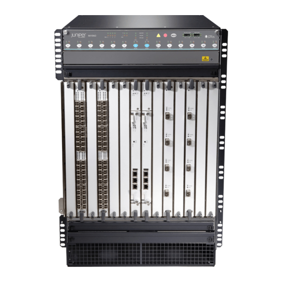
Page 40: Figure 1: Front View Of A Fully Configured Mx960 Router Chassis
MX960 3D Universal Edge Router Hardware Guide Mounting hardware includes front-mounting flanges on the front of the chassis, and two center-mounting brackets attached to the center of the chassis. Figure 1: Front View of a Fully Configured MX960 Router Chassis Copyright © 2017, Juniper Networks, Inc. -
Page 41: Figure 2: Rear View Of A Fully Configured Ac-Powered Mx960 Router
DC Power supplies Power supply ejectors Grounding points ESD point Related MX960 Router Physical Specifications on page 121 Documentation Installing the MX960 Mounting Hardware for a Four-Post Rack or Cabinet on page 195 Copyright © 2017, Juniper Networks, Inc. -
Page 42: Mx960 Component Redundancy
Related MX960 Router Overview on page 3 Documentation Displaying MX960 Router Components and Serial Numbers on page 507 Guidelines for Packing Hardware Components for Shipment on page 524 Returning a Hardware Component to Juniper Networks, Inc. on page 527 MX960 Router Hardware and CLI Terminology Mapping... -
Page 43: Chassis
Chapter 3: Chassis Components and Descriptions Table 5: MX960 Router Hardware Components and CLI Terminology Component Hardware Model Number CLI Name Description Chassis MX960BASE-AC “MX960 Router Physical MX960 Specifications” on page 121 MX960BASE-DC “MX960 Chassis Description” on page 9 Craft Interface Panel... -
Page 44: Mx960 Rack-Mounting Hardware
MX960 3D Universal Edge Router Hardware Guide Table 5: MX960 Router Hardware Components and CLI Terminology (continued) Component Hardware Model Number CLI Name Description SCBE-MX960-S Enhanced MX SCB Transceiver MX Series Interface “Installing an SFP or XFP Xcvr Transceiver into an MX960 DPC, Module Reference MPC, MIC, or PIC”... -
Page 45: Mx960 Craft Interface Overview
Installing the MX960 Mounting Hardware for Front-Mounting in an Open-Frame Rack on page 197 Installing the MX960 Mounting Hardware for a Four-Post Rack or Cabinet on page 195 MX960 Craft Interface Overview The craft interface allows you to view status and troubleshooting information at a glance and to perform many system control functions. -
Page 46: Mx960 Alarm Leds And Alarm Cutoff/Lamp Test Button
The alarm relay contacts are located on the upper right of the craft interface. Figure 5: Alarm Relay Contacts Related Disconnecting the Alarm Relay Wires from the MX960 Craft Interface on page 307 Documentation Connecting the Alarm Relay Wires to the MX960 Craft Interface on page 255 MX960 Alarm LEDs and Alarm Cutoff/Lamp Test Button Two large alarm LEDs are located at the upper right of the craft interface. -
Page 47: Mx960 Component Leds On The Craft Interface
MX960 Host Subsystem LEDs on the Craft Interface on page 17 MX960 Power Supply LEDs on the Craft Interface on page 17 MX960 DPC and MPC LEDs on the Craft Interface on page 18 MX960 FPC LEDs on the Craft Interface on page 18... -
Page 48: Mx960 Dpc And Mpc Leds On The Craft Interface
MX960 3D Universal Edge Router Hardware Guide MX960 DPC and MPC LEDs on the Craft Interface Each DPC or MPC has LEDs on the craft interface that indicate its status. The LEDs, labeled through , and through , are located along the bottom of the craft interface. -
Page 49: Mx960 Fan Leds On The Craft Interface
Fan has failed. Related MX960 Craft Interface Overview on page 15 Documentation MX960 Alarm Relay Contacts on the Craft Interface on page 15 MX960 Cable Manager Description The standard cable manager (see Figure 6 on page 20) is a tray located below the... -
Page 50: Figure 6: Standard Cable Manager
MX960 3D Universal Edge Router Hardware Guide Figure 6: Standard Cable Manager Maintenance linkage Release handles The extended cable manager allows you to route cables away from the front of the DPCs, MPCs, MICs, and PICs, and provides additional access (see... -
Page 51: Figure 8: Extended Cable Manager Cover
Chapter 3: Chassis Components and Descriptions Figure 8: Extended Cable Manager Cover Related Replacing the MX960 Cable Manager on page 310 Documentation Verifying the Version of the MX960 Cable Manager on page 469 Copyright © 2017, Juniper Networks, Inc. - Page 52 MX960 3D Universal Edge Router Hardware Guide Copyright © 2017, Juniper Networks, Inc.
-
Page 53: Cooling System Components And Descriptions
The fan trays are hot-insertable and hot-removable. The MX960 requires high-capacity fan trays to satisfy cooling requirements for high-density DPCs and MPCs. When replacing normal-capacity fan trays with high-capacity fan trays, you must replace them in both the upper and lower fan trays. -
Page 54: Figure 9: Airflow Through The Chassis
MX960 3D Universal Edge Router Hardware Guide At the bottom rear of the chassis, there is an air intake for power supply cooling. Air flows over the power supplies and is exhausted out the rear of the chassis through the smaller air exhaust below the main exhaust. -
Page 55: Mx960 Fan Led
Figure 14: High-Capacity Filter Tray with Air Filter Air filter Air filter tray Related Troubleshooting the MX960 Cooling System on page 490 Documentation Maintaining the MX960 Air Filter on page 446 Maintaining the MX960 Fan Trays on page 446 MX960 Fan LED Each fan has an LED that displays its status. - Page 56 MX960 3D Universal Edge Router Hardware Guide Copyright © 2017, Juniper Networks, Inc.
-
Page 57: Host Subsystem Components And Descriptions
MX960 Midplane Description on page 28 MX960 Routing Engine Description on page 29 MX960 RE-S-1300 and RE-S-2000 Routing Engine LEDs on page 31 RE-S-1800 Routing Engine Description for MX Series on page 31 RE-S-1800 Routing Engine LEDs on page 33... -
Page 58: Mx960 Host Subsystem Leds
MX960 3D Universal Edge Router Hardware Guide Effect of Taking the MX960 Host Subsystem Offline Replacing an MX960 Routing Engine on page 333 Replacing an MX960 SCB on page 409 MX960 Host Subsystem LEDs Each host subsystem has three LEDs that display its status. The host subsystem LEDs are located in the middle of the craft interface. -
Page 59: Mx960 Routing Engine Description
MX960 Router Overview on page 3 Documentation MX960 Chassis Description on page 9 MX960 Dense Port Concentrator Description on page 53 MX960 Modular Port Concentrator Description on page 89 MX960 SCB Description on page 107 MX960 Routing Engine Description on page 29... -
Page 60: Supported Routing Engines
Routing Engine fails or is removed and the backup is configured appropriately, the backup takes over as the master. On the MX960 router, a Routing Engine installed in SCB slot receives no power and supplies no additional routing functions. If no SCB is installed in slot , install a blank panel in the slot. -
Page 61: Mx960 Re-S-1300 And Re-S-2000 Routing Engine Leds
149 RJ-45 Connector Pinouts for an MX Series Routing Engine ETHERNET Port on page 148 Replacing an MX960 Routing Engine on page 333 MX960 RE-S-1300 and RE-S-2000 Routing Engine LEDs Each Routing Engine has four LEDs that indicate its status. The LEDs, labeled... -
Page 62: Re-S-1800 Routing Engine Components
MX960 3D Universal Edge Router Hardware Guide Figure 16: RE-S-1800 Front View Auxiliary Ethernet port port slot 1 slot 2 Extractor clip Console Reset port port button Extractor clip RE-S-1800 Routing Engine Components on page 32 RE-S-1800 Routing Engine Boot Sequence on page 33... -
Page 63: Re-S-1800 Routing Engine Boot Sequence
Documentation page 149 RJ-45 Connector Pinouts for an MX Series Routing Engine ETHERNET Port on page 148 Replacing an MX960 Routing Engine on page 333 Supported Routing Engines by Router on page 40 RE-S-1800 Routing Engine LEDs Each Routing Engine has four LEDs that indicate its status. The LEDs, labeled... -
Page 64: Re-S-X6-64G Routing Engine Description
MX960 3D Universal Edge Router Hardware Guide Table 14: Routing Engine LEDs (continued) Label Color State Description Green Blinking Routing Engine is transitioning online. ONLINE On steadily Routing Engine is functioning normally. OK/FAIL On steadily Routing Engine has failed. Related... -
Page 65: Re-S-X6-64G Routing Engine Boot Sequence
Routing Engine Specifications on page 37 Documentation Upgrading to the RE-S-X6-64G Routing Engine in a Redundant Host Subsystem on page 345 Upgrading to the RE-S-X6-64G Routing Engine in a Nonredundant Host Subsystem on page 351 Copyright © 2017, Juniper Networks, Inc. -
Page 66: Re-S-X6-64G Routing Engine Leds
MX960 3D Universal Edge Router Hardware Guide RE-S-X6-64G Routing Engine LEDs Each Routing Engine has five LEDs that indicate its status. The LEDs—labeled MASTER , and —are located on the faceplate of the Routing Engine. DISK1 DISK2 ONLINE OK/FAIL Table 15 on page 36 describes the functions of the Routing Engine LEDs. -
Page 67: Routing Engine Specifications
Chapter 5: Host Subsystem Components and Descriptions MX960 Routing Engine Description on page 29 Routing Engine Specifications Table 16 on page 37 lists the current specifications for Routing Engines supported on M Series, MX Series, and T Series routers. Table 17 on page 39 lists the specifications for end-of-life Routing Engines. - Page 68 MX960 3D Universal Edge Router Hardware Guide Table 16: Routing Engine Specifications (continued) Routing Connection First Junos OS Engine Processor Memory to PFEs Disk Media Support RE-A-1800x2 1800-MHz 8 GB or 16 GB Gigabit 32 GB SSD 4 GB 10.4...
-
Page 69: Table 17: End-Of-Life Routing Engine Specifications
Pentium M Ethernet disk CompactFlash card NOTE: The memory in Table 16 on page 37 indicates the amount of total memory. To determine the amount of available memory, issue the show chassis routing-engine CLI command. Copyright © 2017, Juniper Networks, Inc. -
Page 70: Supported Routing Engines By Router
MX960 3D Universal Edge Router Hardware Guide On routers that accept two Routing Engines, you cannot mix Routing Engine types except for a brief period (one minute or so) during an upgrade or downgrade to two Routing Engines of the same type. -
Page 71: M10I Routing Engines
Table 20: M40e Routing Engines First Supported Management Internal Ethernet Model Number Name in CLI Output Junos OS Release Ethernet Interface Interface RE-600-2048 (EOL details: fxp0 fxp1 RE-3.0 RE-3.0 TSB14373 (RE-600) fxp2 RE-A-1000-2048 fxp0 fxp1 RE-A-1000 fxp2 Copyright © 2017, Juniper Networks, Inc. -
Page 72: M120 Routing Engines
MX960 3D Universal Edge Router Hardware Guide M120 Routing Engines Table 21 on page 42 lists the Routing Engines supported by the M120 router. Table 21: M120 Routing Engines First First Supported Supported Management Name in CLI 32-bit Junos OS... -
Page 73: Mx5, Mx10, Mx40, And Mx80 Routing Engine
64-bit Junos OS Ethernet Internal Ethernet Number Output Release Release Interface Interface RE-S-MX104 13.2 – fxp0 fxp1 Routing Engine fxp2 MX240 Routing Engines Table 25 on page 44 lists the Routing Engines supported by MX240 routers. Copyright © 2017, Juniper Networks, Inc. -
Page 74: Mx480 Routing Engines
MX960 3D Universal Edge Router Hardware Guide Table 25: MX240 Supported Routing Engines First First Supported Supported Management Internal Name in CLI 32-bit Junos OS 64-bit Junos Ethernet Ethernet Model Number Output Release OS Release Interface Interface RE-S-1300-2048 (EOL –... -
Page 75: Mx960 Routing Engines
– 15.1F4 fxp0 ixlv0, igb0 RE-S-2X00x6 16.1R1 MX960 Routing Engines Table 27 on page 45 lists the Routing Engines supported by MX960 routers. Table 27: MX960 Supported Routing Engines First First Supported Supported Management Internal Name in CLI 32-bit Junos OS... -
Page 76: Mx2008 Routing Engines
MX960 3D Universal Edge Router Hardware Guide Table 27: MX960 Supported Routing Engines (continued) First First Supported Supported Management Internal Name in CLI 32-bit Junos OS 64-bit Junos Ethernet Ethernet Model Number Output Release OS Release Interface Interface RE-S-1800X4-8G 11.4R5 10.4... -
Page 77: Mx2020 Supported Routing Engines
The PTX3000 supports 64-bit Junos OS only. Table 31: PTX3000 Routing Engines First Supported Management Internal Ethernet Model Number Name in CLI Output Junos OS Release Ethernet Interface Interface RE-DUO-C2600-16G RE-DUO-2600 13.2R2 ixgbe0 ixgbe1 RCB-PTX-X6-32G 16.1R4 ixlv0 RE-PTX-2X00x6 ixlv1 Copyright © 2017, Juniper Networks, Inc. -
Page 78: Ptx5000 Routing Engines
MX960 3D Universal Edge Router Hardware Guide PTX5000 Routing Engines Table 32 on page 48 lists the Routing Engines supported on the PTX5000. NOTE: The PTX5000 supports 64-bit Junos OS only. Table 32: PTX5000 Routing Engines Management Name in CLI... -
Page 79: T1600 Routing Engines
64-bit Junos OS Ethernet Ethernet Model Number Output Junos OS Release Release Interface Interface RE-600-2048 (EOL – fxp0 fxp1 RE-3.0 TSB14373 details: RE-3.0 fxp2 (RE-600) RE-1600-2048 (EOL RE-4.0 – fxp0 fxp1 TSB14374 details: (RE-1600) fxp2 Copyright © 2017, Juniper Networks, Inc. -
Page 80: T4000 Routing Engines
MX960 3D Universal Edge Router Hardware Guide Table 35: T1600 Routing Engines (continued) First Supported Management Internal Name in CLI First Supported 32-bit 64-bit Junos OS Ethernet Ethernet Model Number Output Junos OS Release Release Interface Interface RE-A-2000-4096 RE-A-2000 –... -
Page 81: Tx Matrix Plus Routing Engines
Table 39: Routing Engines on TX Matrix Plus with 3D SIBs First Supported First Supported Management Internal Name in CLI 32-bit Junos OS 64-bit Junos OS Ethernet Ethernet Model Number Output Release Release Interface Interface RE-DUO-C2600-16G 64-bit Junos OS: 11.4 ixgbe0 RE-TXP-SFC RE-DUO-2600 ixgbe1 Copyright © 2017, Juniper Networks, Inc. - Page 82 MX960 3D Universal Edge Router Hardware Guide Related Routing Engine Specifications on page 37 Documentation Understanding Internal Ethernet Interfaces Understanding Management Ethernet Interfaces Copyright © 2017, Juniper Networks, Inc.
-
Page 83: Chapter 6 Line Card Components And Descriptions
MX960 Dense Port Concentrator Description on page 53 MX960 Dense Port Concentrator LEDs on page 56 DPCs Supported on MX240, MX480, and MX960 Routers on page 56 MX960 DPC Port and Interface Numbering on page 59 MX960 Dense Port Concentrator Description A Dense Port Concentrator (DPC) is optimized for Ethernet density. -
Page 84: Figure 20: Typical Dpcs Supported By The Router
MX960 3D Universal Edge Router Hardware Guide Figure 20: Typical DPCs Supported by the Router DPC 40x1GE DPC 4x10GE OK / F AIL OK /FA IL 0/0 0/5 2/0 2/5 1/0 1/5 3/0 3/5 The DPC assembly combines packet forwarding and Ethernet interfaces on a single board, with either two or four 10-Gbps Packet Forwarding Engines. -
Page 85: Dpc Components
Chapter 6: Line Card Components and Descriptions Figure 21: DPCs Installed Vertically in the MX960 Router DPC Components Each DPC consists of the following components: DPC cover, which functions as a ground plane and a stiffener. Fabric interfaces. Two Gigabit Ethernet interfaces that allow control information, route information, and statistics to be sent between the Routing Engine and the CPU on the DPCs. -
Page 86: Mx960 Dense Port Concentrator Leds
. For more information about the DPC LEDs on the craft interface, see “MX960 DPC and MPC LEDs on the Craft Interface” on page Each DPC also has LEDs located on the faceplate. For more information about LEDs on the DPC faceplate, see the “LEDs” section for each DPC in the... - Page 87 Chapter 6: Line Card Components and Descriptions Table 40: DPCs Supported in MX240, MX480, and MX960 Routers (continued) Maximum DPC Model Throughput First Junos DPC Name Number Ports per DPC OS Release Gigabit Ethernet Enhanced Ethernet Services DPC with SFP...
- Page 88 MX960 3D Universal Edge Router Hardware Guide Table 40: DPCs Supported in MX240, MX480, and MX960 Routers (continued) Maximum DPC Model Throughput First Junos DPC Name Number Ports per DPC OS Release Mulit-Rate Ethernet Multi-Rate Ethernet Enhanced DPC with SFP and XFP...
-
Page 89: Mx960 Dpc Port And Interface Numbering
Ethernet interface so—SONET/SDH interface xe—10-Gigabit Ethernet interface For a complete list of media types, see Interface Naming Overview. fpc—Slot in which the DPC is installed. On the MX960 router, the DPCs are represented in the CLI as through FPC 0 FPC 11 pic—Logical PIC on the DPC. -
Page 90: Figure 22: Mx960 Dpc Interface Port Mapping
MX960 3D Universal Edge Router Hardware Guide Figure 22: MX960 DPC Interface Port Mapping MIC-3D-40GE-TX ge-3/0/0 ge-3/2/0 ge-3/0/1 ge-3/2/1 ge-3/0/2 ge-3/2/2 ge-3/0/3 ge-3/2/3 ge-3/0/4 ge-3/2/4 ge-3/0/5 ge-3/2/5 ge-3/0/6 ge-3/2/6 ge-3/0/7 ge-3/2/7 0 1 2 3 ge-3/0/8 ge-3/2/8 ge-3/0/9 ge-3/2/9 ge-3/1/0... - Page 91 Copyright © 2017, Juniper Networks, Inc.
-
Page 92: Interface Modules-Fpcs And Pics
A Flexible PIC Concentrator (FPC) occupies two Dense Port Concentrator (DPC) slots on an MX Series router. The MX960 router has 11 dedicated DPC slots and one multifunction slot that supports either a DPC, FPC, or Switch Control Board (SCB). The... -
Page 93: Figure 23: Fpc Installed In The Mx960 Router Chassis
Chapter 6: Line Card Components and Descriptions Figure 23: FPC Installed in the MX960 Router Chassis Figure 24 on page 64 shows the typical FPCs supported on the MX960 router. Copyright © 2017, Juniper Networks, Inc. -
Page 94: Fpc Components
MX960 3D Universal Edge Router Hardware Guide Figure 24: Typical FPCs Supported on the MX960 Router MX-FPC2 FPC3 If a slot is not occupied by a DPC, an FPC, or an SCB, a blank panel must be installed to shield the empty slot and to allow cooling air to circulate properly through the router. -
Page 95: Mx960 Flexible Pic Concentrator (Fpc) Leds
Troubleshooting the MX960 FPCs on page 492 FPCs Supported by MX240, MX480, and MX960 Routers An FPC occupies two slots when installed in an MX240, MX480, or MX960 router. The maximum number of supported FPCs varies per router: MX960 router—6 FPCs MX480 router—3 FPCs... -
Page 96: Mx960 Pic Description
PICs are hot-removable and hot-insertable. Up to two PICs can be installed in the slots in each FPC. Up to six FPCs can be installed in an MX960 router. PICs used in an FPC2 have captive screws at their upper and lower corners. PICs used in a Type 3 FPC have an upper ejector handle and a lower captive screw. -
Page 97: Figure 25: Mx960 Pic Interface Port Mapping
MX Series Interface Module Reference port—Port number. The MX960 supports up to six FPCs that install vertically and are numbered from left to right. Each FPC accepts up to two PICs. Figure 25 on page 67 shows a Channelized OC12/STM4 Enhanced IQ (IQE) PIC with SFP... -
Page 98: Pics Supported By Mx240, Mx480, And Mx960 Routers
Related MX960 Router Hardware and CLI Terminology Mapping on page 12 Documentation PICs Supported by MX240, MX480, and MX960 Routers Table 42 on page 68 lists the PICs supported by MX240, MX480, and MX960 routers. Table 42: PICs Supported by MX240, MX480, and MX960 Routers... -
Page 99: Interface Modules-Mpcs And Mics
MPCs Supported by MX Series Routers on page 92 MX960 Application Services Modular Line Card Description The Application Services Modular Line Card (AS MLC) is an X86-based card for MX960, MX480, and MX240 routers to deliver integrated application service solutions. The first application that network operators can take advantage of is the Junos Content Encore system, a high-throughput, solid state storage platform for media rich content delivery. -
Page 100: Mx960 As Mlc Function
In the future, the AS MLC will run other Juniper Networks router services and applications, and serve as a virtualized platform for third-party applications. The AS MLC provides Ethernet switching and high-speed fabric interface to MX routers. -
Page 101: As Mlc Components
AS MLC Components Each AS MLC consists of the following components: AS MLC Modular Carrier Card (AS MCC), which fits vertically in front of the MX960 router, includes two slots for the Application Services Modular Storage Card (AS MSC) and Application Services Modular Processing Card (AS MXC) -
Page 102: Mx960 Scb, Power Supply, And Cooling System Requirements For As
LED on the AS MCC, which displays the status of the AS MLC MX960 SCB, Power Supply, and Cooling System Requirements for AS MLC Each MX960 router requires specific SCB, power supply, and cooling system models to run the AS MLC. -
Page 103: Mx960 Application Services Modular Processing Card Description
Related MX960 AS MSC LEDs on page 74 Documentation Replacing an MX960 AS MSC on page 318 MX960 Application Services Modular Processing Card Description The Application Services Modular Processing Card (AS MXC) is a pluggable X86-based card that can be inserted into the lower slot of the Application Services Modular Line Card (AS MLC). -
Page 104: Mx960 As Msc Leds
Figure 29: Application Services Modular Processing Card (AS MXC) Related MX960 AS MXC LEDs on page 75 Documentation Replacing an MX960 AS MXC on page 320 MX960 AS MSC LEDs Two LEDs ( ) indicate the status of the AS MSC and are located on the AS MSC. -
Page 105: Mx960 As Mxc Leds
MICs currently supported by MPC1, MPC2, MPC3, MPC6, MPC8, and MPC9 on MX240, MX480, MX960, MX2010, and MX2020 routers. The table lists the first Junos OS release in which the MPC supports the MIC. For example, Junos OS Release 10.2 is the first release in which the MX-MPC1-3D supports the Gigabit Ethernet MIC with SFP. - Page 106 MX960 3D Universal Edge Router Hardware Guide Table 45: MIC/MPC1 Compatibility (continued) MIC Name MPC1 MPC1E MPC1 Q MPC1E Q MIC-3D-20GE-SFP-E 13.2R2 13.2R2 13.2R2 13.2R2 (Gigabit Ethernet MIC with SFP (E)) MIC-3D-2XGE-XFP 10.2 11.2R4 10.2 11.2R4 (10-Gigabit Ethernet MICs with XFP) MIC-3D-4XGE-XFP —...
-
Page 107: Table 46: Mic/Mpc2 Compatibility
Junos with Juno Continuity Continui 15.1 15.1 MIC-3D-4OC3OC12-1OC48, 11.4 11.4 14.1R4, 11.4 11.4 11.4 11.4 14.1R4, MIC-3D-8OC3OC12-4OC48 14.2R3 14.2R3 with Junos with Juno (SONET/SDH OC3/STM1 Continuity Continui (Multi-Rate) MICs with SFP) 15.1 15.1 Copyright © 2017, Juniper Networks, Inc. - Page 108 MX960 3D Universal Edge Router Hardware Guide Table 46: MIC/MPC2 Compatibility (continued) MPC2E MPC2 MPC2E MPC2 MPC2E MPC2E MPC2E MIC Name MPC2 MPC2E NG Q MIC-3D-4COC3-1COC12-CE — — — 12.2 12.2 12.2 12.2 12.2 14.1R4, 14.2R3 (Channelized OC3/STM1 with Juno...
-
Page 109: Table 47: Mic/Mpc3 Compatibility
12.2 14.1R4, 14.2R3 with Junos 14.1R4, 14.2R3 with Junos Continuity Continuity (100-Gigabit Ethernet MIC with CXP) 15.1 15.1 MIC3-100G-DWDM 15.1F5 15.1F5 15.1F5 15.1F6 15.1F6 15.1F6 (100-Gigabit DWDM OTN MIC 17.1R1 17.1R1 17.1R1 with CFP2-ACO) Copyright © 2017, Juniper Networks, Inc. - Page 110 MX960 3D Universal Edge Router Hardware Guide Table 47: MIC/MPC3 Compatibility (continued) MIC Name MPC3E MPC3E NG MPC3E NG Q MIC-3D-4OC3OC12-1OC48 13.3 14.1R4, 14.2R3 with Junos 14.1R4, 14.2R3 with Junos Continuity Continuity MIC-3D-8OC3OC12-4OC48 15.1 15.1 (SONET/SDH OC3/STM1 (Multi-Rate) MICs with SFP) MIC-3D-1OC192-XFP 13.3...
-
Page 111: Table 48: Mic/Mpc6 Compatibility
MPC9E MIC-MRATE 15.1F5 with Junos Continuity 16.1R1 and later MIC MRATE Related MICs Supported by MX Series Routers on page 82 Documentation Junos Continuity Software User Guide (Junos OS Release 14.1R4 and Later Releases) Copyright © 2017, Juniper Networks, Inc. -
Page 112: Mx960 Modular Interface Card Description
Related MICs Supported by MX Series Routers on page 82 Documentation MX960 Modular Interface Card (MIC) LEDs on page 82 Maintaining MX960 MICs on page 462 Troubleshooting the MX960 MICs on page 495 Replacing an MX960 MIC on page 367 MX960 Modular Interface Card (MIC) LEDs Each MIC has LEDs located on the faceplate. -
Page 113: Table 51: Mics Supported By Mx240, Mx480, Mx960, Mx2008, Mx2010, And Mx2020 Routers
Chapter 6: Line Card Components and Descriptions Table 51: MICs Supported by MX240, MX480, MX960, MX2008, MX2010, and MX2020 Routers MX240, MX480, MX960 MX2008 MX2010 MX2020 MIC Name MIC Model Number Ports Routers Routers Routers Routers ATM MIC with SFP MIC-3D-8OC3-2OC12-ATM 12.1... - Page 114 MX960 3D Universal Edge Router Hardware Guide Table 51: MICs Supported by MX240, MX480, MX960, MX2008, MX2010, and MX2020 Routers (continued) MX240, MX480, MX960 MX2008 MX2010 MX2020 MIC Name MIC Model Number Ports Routers Routers Routers Routers 100-Gigabit Ethernet MIC with MIC3-3D-1X100GE-CXP 12.2...
-
Page 115: Table 52: Mics Supported By Mx5, Mx10, Mx40, Mx80, And Mx104 Routers
Chapter 6: Line Card Components and Descriptions Table 51: MICs Supported by MX240, MX480, MX960, MX2008, MX2010, and MX2020 Routers (continued) MX240, MX480, MX960 MX2008 MX2010 MX2020 MIC Name MIC Model Number Ports Routers Routers Routers Routers Multiservices MIC MS-MIC-16G 13.2... -
Page 116: Mx960 Mic Port And Interface Numbering
MX960 3D Universal Edge Router Hardware Guide Table 52: MICs Supported by MX5, MX10, MX40, MX80, and MX104 Routers (continued) MIC Name MIC Model Number P o r t s MX10 MX40 MX80 M X 1 0 4 SONET/SDH OC3/STM1 MIC-3D-8OC3OC12-4OC48 11.2R4... - Page 117 Ethernet interface so—SONET/SDH interface xe—10-Gigabit Ethernet interface For a complete list of media types, see Interface Naming Overview. fpc—Slot in which the MPC is installed. On the MX960 router, the MPCs are represented in the CLI as through FPC 0 FPC 11 pic—Logical PIC on the MIC, numbered 0 or 1 when installed in MIC slot 0 and 2 or 3...
-
Page 118: Figure 30: Port Mapping For The 20-Port Gigabit Ethernet Mic With Sfp Installed
MX960 3D Universal Edge Router Hardware Guide NOTE: The 20-port Gigabit Ethernet MIC with SFP-E has a different port numbering. See Gigabit Ethernet MIC with SFP (E) Figure 30: Port Mapping for the 20-Port Gigabit Ethernet MIC with SFP Installed in the MX960... -
Page 119: Mx960 Modular Port Concentrator Description
Related MX960 Router Hardware and CLI Terminology Mapping on page 12 Documentation MX960 Modular Port Concentrator Description Modular Port Concentrators (MPCs) provide packet forwarding services. The MPCs are inserted into a slot in a router. Modular Interface Cards (MICs) provide the physical interfaces and install into the MPCs. -
Page 120: Figure 31: Typical Mpc Supported On The Mx960 Router
MPCs interface with the power supplies and Switch Control Boards (SCBs). You must install redundant SCBs to support full line rate. The MX960 router supports up to 12 MPCs. You must install a high-capacity fan tray to use an MPC. For power requirements, see “Calculating Power Requirements for MX960... -
Page 121: Mpc Components
Chapter 6: Line Card Components and Descriptions Figure 32: MPC Installed Vertically in the MX960 Router MPC Components Each MPC consists of the following components: MPC card carrier, which includes two MIC slots (excludes the fixed configuration MPC). Fabric interfaces. -
Page 122: Mx960 Modular Port Concentrator Leds
Table 53 on page 92 lists the MPCs and their first supported Junos OS release on MX240, MX480, MX960, MX2008, MX2010, and MX2020 routers. Table 53: MPCs Supported by MX240, MX480, MX960, MX2008, MX2010, and MX2020 Routers First Junos OS Release on... - Page 123 Chapter 6: Line Card Components and Descriptions Table 53: MPCs Supported by MX240, MX480, MX960, MX2008, MX2010, and MX2020 Routers (continued) First Junos OS Release on First Junos OS First Junos OS First Junos OS MX240, Release on Release on...
- Page 124 MX960 3D Universal Edge Router Hardware Guide Table 53: MPCs Supported by MX240, MX480, MX960, MX2008, MX2010, and MX2020 Routers (continued) First Junos OS Release on First Junos OS First Junos OS First Junos OS MX240, Release on Release on...
- Page 125 Chapter 6: Line Card Components and Descriptions Table 53: MPCs Supported by MX240, MX480, MX960, MX2008, MX2010, and MX2020 Routers (continued) First Junos OS Release on First Junos OS First Junos OS First Junos OS MX240, Release on Release on...
- Page 126 MX960 3D Universal Edge Router Hardware Guide Copyright © 2017, Juniper Networks, Inc.
-
Page 127: Chapter 7 Power System Components And Descriptions
MX960 DC Power Supply LEDs on page 105 MX960 Power System Overview The MX960 router uses either AC or DC power supplies. The MX960 router is configurable with three or four normal-capacity AC power supplies, up to four high-capacity DC power supplies, and up to four high-capacity AC power supplies. -
Page 128: Mx960 Ac Power Supply Description
MX960 DC Power Supply on page 104 MX960 AC Power Supply Description The MX960 requires special power supplies that are not interchangeable with the MX240, MX480, or the MX2000 series routers. Two types of AC power supplies can be used: normal-capacity or high-capacity. -
Page 129: Figure 33: Mx960 Normal-Capacity Ac Power Supply
ESD point The minimum number of power supplies must be present in the router at all times. Refer Table 54 on page Table 54: Minimum Number of Power Supplies Required for the MX960 Router Model Configuration Minimum Required Number of Power... -
Page 130: Normal-Capacity Ac Power Supplies
(4100W). To operate the MX960 at full capacity, you must use two-feed mode. High-capacity power supplies require one power cord per feed. Therefore, to operate the MX960 at full capacity, you will need two power cords. -
Page 131: Understanding Input Mode Switch (Dip Switch) Settings
1+1 per zone.Table 55 on page 101 lists the components that receive power for each zone in a high-capacity AC power supply configuration. Table 55: Zoning for High-Capacity Power Supplies in an MX960 Chassis Power Configuration Zone Power Supply (PEM) - Page 132 DIP switch is set to position 1. Related MX960 Router Grounding Specifications on page 145 Documentation Electrical Specifications for the MX960 AC Power Supply on page 151 Copyright © 2017, Juniper Networks, Inc.
-
Page 133: Mx960 Ac Power Supply Leds
Calculating Power Requirements for MX960 Routers on page 161 Power Requirements for an MX960 Router on page 152 AC Power Circuit Breaker Requirements for the MX960 Router on page 165 AC Power Cord Specifications for the MX960 Router on page 165... -
Page 134: Mx960 Dc Power Supply
MX960 3D Universal Edge Router Hardware Guide MX960 DC Power Supply In the DC power configuration, the router contains either two or four DC power supplies (see Figure 36 on page 104), located at the lower rear of the chassis in slots... -
Page 135: Mx960 Dc Power Supply Leds
MX960 Router Grounding Specifications on page 145 Calculating Power Requirements for MX960 Routers on page 161 DC Power Circuit Breaker Requirements for the MX960 Router on page 183 DC Power Source Cabling for the MX960 Router on page 183 DC Power Cable Specifications for the MX960 Router on page 185... -
Page 136: Table 58: Dc Power Supply Leds
DC input is present and is connected in correct polarity. Yellow DC input is present, but connected in reverse polarity. Related MX960 Power Supply LEDs on the Craft Interface on page 17 Documentation MX960 Power System Overview on page 97 MX960 AC Power Supply Description on page 98... -
Page 137: Switch Fabric Components And Descriptions
CHAPTER 8 Switch Fabric Components and Descriptions MX960 SCB Description on page 107 MX960 Switch Control Board LEDs on page 109 MX960 SCBE Description on page 110 MX960 SCBE LEDs on page 112 SCBE2-MX Description on page 113 SCBE2-MX LEDs on page 117... -
Page 138: Scb Slots
MX960 3D Universal Edge Router Hardware Guide Figure 38: SCB SCB Slots You can install up to three. The SCBs install vertically into the front of the chassis in the slots labeled , and . If any slots are empty, you must install a blank panel. -
Page 139: Scb Components
MX960 Host Subsystem Description on page 27 Documentation MX960 Routing Engine Description on page 29 MX960 Switch Control Board LEDs on page 109 Replacing an MX960 SCB on page 409 MX960 Switch Control Board LEDs Three LEDs on the SCB indicate the status of the SCB. The LEDs, labeled... -
Page 140: Mx960 Scbe Description
(slot and capacity scale), as well as improved services. The upgraded SCB is supported on MX960, MX480, and MX240 routers. Some key attributes of the MX SCBE are: 160 Gbps/slot bandwidth with redundant fabric support, and improved fabric... -
Page 141: Mx Scbe Slots
Gigabit Ethernet switch that is connected to the embedded CPU complex on all components External clock interface—Allows BITS or GPS clock source input to the centralized timing circuit, or allows centralized timing to be output to BITS or GPS Copyright © 2017, Juniper Networks, Inc. -
Page 142: Mx960 Scbe Leds
LEDs—Provide status of the SCBE and clocking interface Related MX960 SCB Description on page 107 Documentation MX960 SCBE LEDs on page 112 Upgrading an MX960 SCB to SCBE on page 413 MX960 SCBE LEDs , and LEDs indicate the status of the MX FABRIC ACTIVE... -
Page 143: Scbe2-Mx Description
(slot and capacity scale) as well as improved services. The SCBE2-MX was released with Junos release 13.3R1. The SCBE2-MX is installed vertically in the MX960 chassis and horizontally in the MX480 and MX240 chassis. The routing engine is installed directly into a slot on the SCBE2-MX... -
Page 144: Figure 40: Scbe2-Mx
Requirements For proper cooling, you must install MX-series high-capacity fan trays in the MX chassis. Additionally, for the MX960, you must install a high-capacity filter tray. SCBE2-MX Features Provides improved fabric performance for high-capacity line cards using the third generation fabric XF2 chip. - Page 145 . If any slots are empty, you must install a blank panel. The two SCBE2-MX’s residing in slot 6 and slot 7 of the MX960 chassis provide both control and switch fabric features, while the third SCBE2-MX residing in slot 8 of the chassis (hybrid slot) will only do fabric functions.
-
Page 146: Scbe2 Interoperability With Existing Hardware
MX960 3D Universal Edge Router Hardware Guide Maximum Power SCBE2-MX (applies to MX240, MX480, and MX960) Requirements 185 W at 55° C 160 W at 40° C 155 W at 25° C LEDs , and LEDs indicate the status of the SCBE2-MX. -
Page 147: Scbe2-Mx Leds
On steadily UTI clocking interface has failed. – UTI clocking interface is offline. Green On steadily Port is enabled and link is established. LINK – Port is disabled or no link is established. Copyright © 2017, Juniper Networks, Inc. - Page 148 MX960 3D Universal Edge Router Hardware Guide Related SCBE2-MX Description on page 113 Documentation MX-Series Switch Control Board (SBC) Overview Copyright © 2017, Juniper Networks, Inc.
-
Page 149: Site Planning, Preparation, And Specifications
Preparation Overview on page 121 Transceiver and Cable Specifications on page 133 Pinout Specifications on page 145 AC Power Requirements, Specifications, and Guidelines on page 151 DC Power Requirements, Specifications, and Guidelines on page 169 Copyright © 2017, Juniper Networks, Inc. - Page 150 MX960 3D Universal Edge Router Hardware Guide Copyright © 2017, Juniper Networks, Inc.
-
Page 151: Preparation Overview
MX960 Router Environmental Specifications on page 124 MX960 Site Preparation Checklist on page 124 MX960 Rack Requirements on page 125 Clearance Requirements for Airflow and Hardware Maintenance for the MX960 Router on page 128 MX960 Cabinet Size and Clearance Requirements on page 130... - Page 152 MX960 3D Universal Edge Router Hardware Guide Table 63: Physical Specifications (continued) Description Weight Width Depth Height Router with extended cable Chassis with 17.37 in. (44.11 cm) 23.0 in. (58.42 cm) 36.5 in. (92.7 cm) high manager installed midplane, two fan...
- Page 153 6.7 in (17 cm) Extended cable manager 39 lb (2.3 kg) 24.5 in (62.2 cm) 30 in (78 cm) 24.25 in (61.6 cm) Related MX960 Router Overview on page 3 Documentation MX960 Chassis Description on page 9 Copyright © 2017, Juniper Networks, Inc.
-
Page 154: Mx960 Router Environmental Specifications
Articles 110-16, 110-17, and 110-18 of the National Electrical Code, ANSI/NFPA 70. Related Tools and Parts Required to Maintain the MX960 Router on page 445 Documentation Definition of Safety Warning Levels MX960 Site Preparation Checklist... -
Page 155: Mx960 Rack Requirements
Power Margin for Fiber-Optic Cables” on page 140 Related Installing an MX960 Router Overview on page 203 Documentation Unpacking the MX960 Router on page 189 MX960 Rack Requirements The router can be installed in many types of racks, including four-post (telco) racks and open-frame racks. -
Page 156: Rack Size And Strength
MX960 3D Universal Edge Router Hardware Guide Figure 41: Typical Open-Frame Rack Rack Size and Strength on page 126 Spacing of Mounting Bracket Holes on page 127 Connection to the Building Structure on page 128 Rack Size and Strength The size, strength, and location of the rack must accommodate the router's weight and external dimensions. -
Page 157: Spacing Of Mounting Bracket Holes
36.5 in. (92.7 cm) high (approximately 21 U). You can stack two MX960 routers in a rack that has at least 48 U (89.3 in. or 2.24 m). The rack must be able to accomodate the additional depth of the extended cable manager. -
Page 158: Connection To The Building Structure
36.5 in. (92.7 cm) high 29.00 in. (73.7 cm) deep approximately Additional clearance is also required to accommodate the depth of the MX960 high-capacity power supplies; they extend beyond the chassis as shown in Table 66 on page 128. -
Page 159: Figure 42: Chassis Dimensions And Clearance Requirements For The Mx960 Router With The Normal-Capacity Power Supplies
(48.7 cm) (44.2 cm) Standard cable manager Extended cable manager Front-mounting flange Figure 43: Chassis Dimensions and Clearance Requirements for the MX960 Router with the Standard Cable Manager and High-Capacity DC Power Supplies 34.8" (88.4 cm) 24" (61 cm) clearance required 39.3"... -
Page 160: Mx960 Cabinet Size And Clearance Requirements
The minimum total clearance inside the cabinet is 39.4 in or 1000 mm. between the inside of the front door and the inside of the rear door. Related Clearance Requirements for Airflow and Hardware Maintenance for the MX960 Router Documentation on page 128... -
Page 161: Figure 44: Airflow Through The Chassis
Chapter 9: Preparation Overview Figure 44: Airflow Through the Chassis Related Clearance Requirements for Airflow and Hardware Maintenance for the MX960 Router Documentation on page 128 MX960 Cabinet Size and Clearance Requirements on page 130 MX960 Rack Requirements on page 125 MX960 Rack-Mounting Hardware on page 14 Copyright ©... - Page 162 MX960 3D Universal Edge Router Hardware Guide Copyright © 2017, Juniper Networks, Inc.
-
Page 163: Transceiver And Cable Specifications
Routing Engine Interface Cable and Wire Specifications for MX Series Routers on page 142 Network Cable and Transceiver Overview for ACX Series and M Series Routers Juniper Networks devices support a variety of fixed and pluggable transceivers and network cable, including multimode and single-mode fiber-optic cable. For a list of... -
Page 164: Supported Network Interface Standards By Transceiver For Acx Series, Mx Series, M Series, And T Series Routers
(JTAC) can help you diagnose the source of the problem. Your JTAC engineer might recommend that you check the third-party optic or cable and potentially replace it with an equivalent Juniper Networks optic or cable that is qualified for the device. -
Page 165: Transceiver And Cable Specifications
Ethernet 10BASE, Fast Ethernet 100BASE, and Gigabit Ethernet 1000BASE Specifications 100BASE-FX SFP-1FE-FX 10/100/1000 BASE-T SFP-1GE-FE-E-T 1000BASE-LH SFP-1GE-LH 1000BASE-LX SFP-1GE-LX 1000BASE-LX10 1000BASE-SX SFP-1GE-SX 1000BASE-T SFP-1GE-T 100BASE-BX SFP-FE20KT13R15 SFP-FE20KT15R13 1000BASE-BX SFP-GE10KT13R14 SFP-GE10KT13R15 SFP-GE10KT14R13 SFP-GE10KT15R13 SFP-GE40KT13R15 SFP-GE40KT15R13 1000BASE-EX SFP-GE40KM Copyright © 2017, Juniper Networks, Inc. - Page 166 MX960 3D Universal Edge Router Hardware Guide Table 67: Supported Ethernet Standards (continued) Standard Transceiver Specifications SFP CWDM SFP-GE80KCW1470-ET SFP-GE80KCW1490-ET SFP-GE80KCw1510-ET SFP-GE80KCW1530-ET SFP-GE80KCW1550-ET SFP-GE80KCW1570-ET SFP-GE80KCW1590-ET SFP-GE80KCW1610-ET 10-Gigabit Ethernet 10GBASE Specifications 10-Gigabit Ethernet dense SFPP-10GE-LRM wavelength-division multiplexing (DWDM) PC-1XGE-DWDM-CBAND 10-Gigabit Ethernet dense...
- Page 167 40-Gigabit Ethernet 40GBASE Specifications 40GBASE-LR4 CFP-40GBASE-LR4 40GBASE-LX4 QSFPP-40G-LX4 40GBASE-ER4 QSFPP-40GBASE-ER4 40GBASE-LR4 QSFPP-40GBASE-LR4 40GBASE-SR4 QSFPP-40GBASE-SR4 100-Gigabit Ethernet 100GBASE-R Specifications 100GBASE-ER4 CFP-100GBASE-ER4 100GBASE-ER4 CFP-GEN2-CGE-ER4 100GBASE-LR4 CFP-100GBASE-LR4 100GBASE-LR4 CFP-GEN2-100GBASE-LR4 100GBASE-SR10 CFP-100GBASE-SR10 Juniper Networks Proprietary CFP-100GBASE-ZR 100GBASE-LR4 CFP2-100GBASE-LR4 Copyright © 2017, Juniper Networks, Inc.
-
Page 168: Table 68: Supported Sonet Standards
MX960 3D Universal Edge Router Hardware Guide Table 67: Supported Ethernet Standards (continued) Standard Transceiver Specifications 100GBASE-ER4 CFP2-100G-ER4-D 100GBASE-SR10 CFP2-100G-SR10-D3 100GBASE-SR10 CXP-100GBASE-SR10 100G-SR4 QSFP-100GBASE-SR4 100G-LR4 CFP-100GBASE-LR4 100-Gigabit DWDM OTN TCFP2-100G-C Table 68 on page 138 is organized by transmission speed and then alphabetically by model number. -
Page 169: Understanding Fiber-Optic Cable Signal Loss, Attenuation, And Dispersion
Interfaces with single-mode optics use lasers as light sources. Lasers generate a single wavelength of light, which travels in a straight line through the single-mode fiber. Compared with multimode fiber, single-mode fiber has higher bandwidth and can carry signals for longer distances. Copyright © 2017, Juniper Networks, Inc. -
Page 170: Attenuation And Dispersion In Fiber-Optic Cable
(including those from dispersion), and a safety margin for unexpected losses. Related Determining Transceiver Support and Specifications for Juniper Networks Devices Documentation Calculating Power Budget and Power Margin for Fiber-Optic Cables Use the information in this topic and the specifications for your optical interface to calculate the power budget and power margin for fiber-optic cables. -
Page 171: Calculating Power Budget For Fiber-Optic Cable
Table 69: Estimated Values for Factors Causing Link Loss Link-Loss Factor Estimated Link-Loss Value Higher-order mode losses Single-mode—None Multimode—0.5 dB Modal and chromatic dispersion Single-mode—None Multimode—None, if product of bandwidth and distance is less than 500 MHz-km Copyright © 2017, Juniper Networks, Inc. -
Page 172: Routing Engine Interface Cable And Wire Specifications For Mx Series
MX960 3D Universal Edge Router Hardware Guide Table 69: Estimated Values for Factors Causing Link Loss (continued) Link-Loss Factor Estimated Link-Loss Value Connector 0.5 dB Splice 0.5 dB Fiber attenuation Single-mode—0.5 dB/km Multimode—1 dB/km The following sample calculation for a 2-km-long multimode link with a power budget... -
Page 173: Table 70: Cable And Wire Specifications For Routing Engine Management And Alarm Interfaces
28-AWG and 14-AWG (0.08 and 2.08 mm Related MX960 Routing Engine Description on page 29 Documentation Replacing Connections to MX960 Routing Engine Interface Ports on page 343 Replacing an MX960 Routing Engine on page 333 Copyright © 2017, Juniper Networks, Inc. - Page 174 MX960 3D Universal Edge Router Hardware Guide Copyright © 2017, Juniper Networks, Inc.
-
Page 175: Pinout Specifications
Ports on page 149 MX960 Router Grounding Specifications MX960 Chassis Grounding Points Specifications on page 145 MX960 Router Grounding Cable Lug Specifications on page 147 MX960 Router Grounding Cable Specifications on page 148 MX960 Chassis Grounding Points Specifications To meet safety and electromagnetic interference (EMI) requirements and to ensure proper operation, the router must be adequately grounded before power is connected. -
Page 176: Figure 45: Connecting Ac Power To The Router
MX960 3D Universal Edge Router Hardware Guide Figure 45: Connecting AC Power to the Router Copyright © 2017, Juniper Networks, Inc. -
Page 177: Mx960 Router Grounding Cable Lug Specifications
Chapter 11: Pinout Specifications Figure 46: Connecting DC Power to the Router MX960 Router Grounding Cable Lug Specifications CAUTION: Before router installation begins, a licensed electrician must attach a cable lug to the grounding and power cables that you supply. A cable with an incorrectly attached lug can damage the router. -
Page 178: Mx960 Router Grounding Cable Specifications
Related Grounding the MX960 Router on page 226 Documentation Tools and Parts Required for MX960 Router Grounding and Power Connections on page 225 RJ-45 Connector Pinouts for an MX Series Routing Engine ETHERNET Port The port on the Routing Engine labeled... -
Page 179: Connector Pinouts For Mx Series Routing Engine Aux And Console
Related MX960 Routing Engine Description on page 29 Documentation Replacing Connections to MX960 Routing Engine Interface Ports on page 343 Replacing an MX960 Routing Engine on page 333 RJ-45 Connector Pinouts for MX Series Routing Engine AUX and CONSOLE Ports... - Page 180 MX960 3D Universal Edge Router Hardware Guide Related MX960 Routing Engine Description on page 29 Documentation Replacing Connections to MX960 Routing Engine Interface Ports on page 343 Replacing an MX960 Routing Engine on page 333 Copyright © 2017, Juniper Networks, Inc.
-
Page 181: Ac Power Requirements, Specifications, And Guidelines
Power Requirements for an MX960 Router on page 152 Calculating Power Requirements for MX960 Routers on page 161 AC Power Circuit Breaker Requirements for the MX960 Router on page 165 AC Power Cord Specifications for the MX960 Router on page 165... -
Page 182: Power Requirements For An Mx960 Router
Power Requirements for an MX960 Router Table 75 on page 153 lists the MX960 base system and cooling system power requirements. Table 76 on page 153 lists the FRU power requirements for Switch Control Boards (SCBs), Routing Engines, Modular Port Concentrators (MPCs), Modular Interface Cards (MICs), Dense Port Concentrators (DPCs), and PICs. -
Page 183: Table 75: Mx960 Common Component Power Requirements
Chapter 12: AC Power Requirements, Specifications, and Guidelines Table 75: MX960 Common Component Power Requirements Component Maximum Power Requirement Typical Power Requirement Base system 50 W 50 W Normal-capacity cooling system 600 W (full speed) 400 W (normal speed) High-capacity cooling system... - Page 184 MX960 3D Universal Edge Router Hardware Guide Table 76: FRU Power Requirements (continued) Component Part Number Maximum Power Requirement 32x10GE M P C 4 E - 3 D - 3 2 X G E - S F P P 610 W...
- Page 185 417 W at 40° C 400 W at 25° C MPC2E NG Q MPC2E-3D-NG-Q 529 W With MICs and optics: 529 W at 55° C 460 W at 40° C 438 W at 25° C Copyright © 2017, Juniper Networks, Inc.
- Page 186 MX960 3D Universal Edge Router Hardware Guide Table 76: FRU Power Requirements (continued) Component Part Number Maximum Power Requirement MPC3E MX-MPC3E-3D 440 W With MICs and optics: 500 W at 55° C, two 40W MICs 485 W at 40° C, two CFP MICs with LR4 optics 473 W at 25°...
- Page 187 29 W at 55° C 27.75 W at 40° C 26.5 W at 25° C SONET/SDH MIC-3D-1OC192-XFP 41 W at 55° C OC192/STM64 38.5 W at 40° C MIC with XFP 36 W at 25° C Copyright © 2017, Juniper Networks, Inc.
- Page 188 MX960 3D Universal Edge Router Hardware Guide Table 76: FRU Power Requirements (continued) Component Part Number Maximum Power Requirement Channelized 4-Port: 4-Port: SONET/SDH M I C - 3 D - 4 C H O C 3 - 2 C H O C 1 2 41 W at 55°...
- Page 189 XFP (2-Port) 10-Gigabit DPCE-R-4XGE-XFP 310 W Ethernet DPCE-X-4XGE-XFP Enhanced DPC with XFP (4-Port) 10-Gigabit DPCE-R-Q-4XGE-XFP 330 W Ethernet DPCE-X-Q-4XGE-XFP Enhanced Queuing Ethernet Services DPC with XFP or Enhanced Queuing IP Services DPC with XFP Copyright © 2017, Juniper Networks, Inc.
- Page 190 FPC Type 3 MX-FPC3 265 W (with PICs and optics) Related Electrical Specifications for the MX960 DC Power Supply on page 169 Documentation Electrical Specifications for the MX960 AC Power Supply on page 151 Copyright © 2017, Juniper Networks, Inc.
-
Page 191: Calculating Power Requirements For Mx960 Routers
We recommend that you provision power according to the maximum input current listed in the power supply electrical specifications (see “Electrical Specifications for the MX960 AC Power Supply” on page 151 “Electrical Specifications for the MX960 DC Power Supply” on page 169). Use the following procedures to calculate the power requirement: Calculate the power requirement. -
Page 192: Table 77: Mx960 Zoning
MX960 3D Universal Edge Router Hardware Guide Both normal-capacity and high-capacity MX960 chassis with DC power supplies and MX960 chassis with high-capacity AC power supplies are zoned. MX960 chassis with normal-capacity AC power supplies have one overall zone. Zoning means that certain... -
Page 193: Table 78: Sample Power Requirements For An Mx960 Router
Calculate the power requirements (usage) using the values in “Power Requirements for an MX960 Router” on page 152 as shown in Table 78 on page 163. Table 78: Sample Power Requirements for an MX960 Router Chassis Component Part Number Power Requirement Zone Base system... -
Page 194: Table 80: Calculating Input Power
Table 80 on page 164. NOTE: MX960 AC and MX960 DC normal-capacity power supplies are not included in the following table, because their power budget was exceeded in the sample configuration. Table 80: Calculating Input Power... -
Page 195: Ac Power Circuit Breaker Requirements For The Mx960 Router
Power Requirements for an MX960 Router on page 152 Documentation Electrical Specifications for the MX960 AC Power Supply on page 151 Electrical Specifications for the MX960 DC Power Supply on page 169 AC Power Circuit Breaker Requirements for the MX960 Router Each AC power supply has a single AC appliance inlet located in the chassis directly above the power supply that requires a dedicated AC power feed. -
Page 196: Figure 48: Ac Plug Types
MX960 3D Universal Edge Router Hardware Guide each HC AC power supply. For more information about AC power supplies, see “MX960 AC Power Supply Description” on page 98 Table 82 on page 166 provides specifications and Figure 48 on page 166 depicts the plug on the AC power cord provided for each country or region. - Page 197 Related MX960 AC Power Supply Description on page 98 Documentation Connecting Power to an AC-Powered MX960 Router with Normal-Capacity Power Supplies on page 227 Replacing an MX960 AC Power Supply Cord on page 403 Copyright © 2017, Juniper Networks, Inc.
- Page 198 MX960 3D Universal Edge Router Hardware Guide Copyright © 2017, Juniper Networks, Inc.
-
Page 199: Dc Power Requirements, Specifications, And Guidelines
Power Requirements for an MX960 Router on page 171 Calculating Power Requirements for MX960 Routers on page 179 DC Power Circuit Breaker Requirements for the MX960 Router on page 183 DC Power Source Cabling for the MX960 Router on page 183... -
Page 200: Table 84: Power System Electrical Specifications
5600 W 8200 W 3400 W per system Related Calculating Power Requirements for MX960 Routers on page 161 Documentation MX960 DC Power Supply on page 104 MX960 DC Power Electrical Safety Guidelines show chassis power Copyright © 2017, Juniper Networks, Inc. -
Page 201: Power Requirements For An Mx960 Router
Chapter 13: DC Power Requirements, Specifications, and Guidelines Power Requirements for an MX960 Router Table 75 on page 153 lists the MX960 base system and cooling system power requirements. Table 76 on page 153 lists the FRU power requirements for Switch Control Boards (SCBs), Routing Engines, Modular Port Concentrators (MPCs), Modular Interface Cards (MICs), Dense Port Concentrators (DPCs), and PICs. - Page 202 MX960 3D Universal Edge Router Hardware Guide Table 86: FRU Power Requirements (continued) Component Part Number Maximum Power Requirement Routing RE-S-1300-2048 90 W Engines RE-S-1800X2-8G RE-S-1800X4-8G RE-S-1800X2-16G RE-S-1800X4-16G RE-S-1800X4-32G RE-S-2000-4096 RE-S-X6-64G Fixed Configuration MPCs 16x10GE MPC MPC-3D-16XGE-SFPP 440 W at 55° C ambient M P C - 3 D - 1 6 X G E - S F P P - R - B 423 W at 25°...
- Page 203 315 W at 25° C MPC2 Q MX-MPC2-3D-Q 294 W MPC2E Q MX-MPC2E-3D-Q With MICs and optics: 368 W at 55° C MPC2 EQ MX-MPC2-3D-EQ 347 W at 40° C MPC2E EQ MX-MPC2E-3D-EQ 333 W at 25° C Copyright © 2017, Juniper Networks, Inc.
- Page 204 MX960 3D Universal Edge Router Hardware Guide Table 86: FRU Power Requirements (continued) Component Part Number Maximum Power Requirement MPC2E P MX-MPC2E-3D-P 294 W With MICs and optics: 368 W at 55° C 347 W at 40° C 333 W at 25° C...
- Page 205 CFP 100-Gigabit MI C 3-3D-1X100GE-CXP 20 W Ethernet MIC with CXP 100-Gigabit MIC3-100G-DWDM With optics: DWDM OTN 91 W at 55° C MIC with CFP2 83 W at 25° C Multiservices MS-MIC-16G 60 W Copyright © 2017, Juniper Networks, Inc.
- Page 206 MX960 3D Universal Edge Router Hardware Guide Table 86: FRU Power Requirements (continued) Component Part Number Maximum Power Requirement SONET/SDH 4-Port: 4-Port: OC3/STM1 M I C - 3 D - 4 O C 3 O C 1 2 - 1 O C 4 8 24 W at 55°...
- Page 207 Services DPCs with SFP (20-Port) 10-Gigabit DPC-R-4XGE-XFP 310 W Ethernet DPC with XFP 10-Gigabit DPCE-R-2XGE-XFP 175 W Ethernet Enhanced DPC with XFP (2-Port) 10-Gigabit DPCE-R-4XGE-XFP 310 W Ethernet DPCE-X-4XGE-XFP Enhanced DPC with XFP (4-Port) Copyright © 2017, Juniper Networks, Inc.
- Page 208 FPC Type 3 MX-FPC3 265 W (with PICs and optics) Related Electrical Specifications for the MX960 DC Power Supply on page 169 Documentation Electrical Specifications for the MX960 AC Power Supply on page 151 Copyright © 2017, Juniper Networks, Inc.
-
Page 209: Calculating Power Requirements For Mx960 Routers
We recommend that you provision power according to the maximum input current listed in the power supply electrical specifications (see “Electrical Specifications for the MX960 AC Power Supply” on page 151 “Electrical Specifications for the MX960 DC Power Supply” on page 169). Use the following procedures to calculate the power requirement: Calculate the power requirement. -
Page 210: Table 87: Mx960 Zoning
MX960 3D Universal Edge Router Hardware Guide Both normal-capacity and high-capacity MX960 chassis with DC power supplies and MX960 chassis with high-capacity AC power supplies are zoned. MX960 chassis with normal-capacity AC power supplies have one overall zone. Zoning means that certain... -
Page 211: Table 88: Sample Power Requirements For An Mx960 Router
Calculate the power requirements (usage) using the values in “Power Requirements for an MX960 Router” on page 152 as shown in Table 78 on page 163. Table 88: Sample Power Requirements for an MX960 Router Chassis Component Part Number Power Requirement Zone Base system... -
Page 212: Table 90: Calculating Input Power
Table 80 on page 164. NOTE: MX960 AC and MX960 DC normal-capacity power supplies are not included in the following table, because their power budget was exceeded in the sample configuration. Table 90: Calculating Input Power... -
Page 213: Dc Power Circuit Breaker Requirements For The Mx960 Router
Power Requirements for an MX960 Router on page 152 Documentation Electrical Specifications for the MX960 AC Power Supply on page 151 Electrical Specifications for the MX960 DC Power Supply on page 169 DC Power Circuit Breaker Requirements for the MX960 Router If you plan to operate a maximally configured DC-powered router with normal capacity power suplies, we recommend that you provision at least 116 A (58 A per feed) @ –48... -
Page 214: Figure 49: Typical Dc Source Cabling To The Router
Power cords and cables must not block access to device components or drape where people could trip on them. Related General Electrical Safety Guidelines and Electrical Codes for Juniper Networks Devices Documentation MX960 DC Power Supply on page 104 Connecting Power to a DC-Powered MX960 Router with Normal-Capacity Power... -
Page 215: Dc Power Cable Specifications For The Mx960 Router
Chapter 13: DC Power Requirements, Specifications, and Guidelines Connecting an MX960 DC Power Supply Cable on page 244 DC Power Cable Specifications for the MX960 Router on page 185 DC Power Cable Specifications for the MX960 Router The accessory box shipped with the router includes the cable lugs that attach to the... - Page 216 MX960 DC Power Supply on page 104 Documentation MX960 DC Power Electrical Safety Guidelines DC Power Source Cabling for the MX960 Router on page 183 Connecting an MX960 DC Power Supply Cable on page 244 Copyright © 2017, Juniper Networks, Inc.
-
Page 217: Initial Installation And Configuration
Installing the MX960 Router on page 203 Connecting the MX960 Router to Power on page 225 Connecting the MX960 Router to the Network on page 247 Initially Configuring the MX960 Router on page 257 Copyright © 2017, Juniper Networks, Inc. - Page 218 MX960 3D Universal Edge Router Hardware Guide Copyright © 2017, Juniper Networks, Inc.
-
Page 219: Unpacking The Mx960 Router
CHAPTER 14 Unpacking the MX960 Router Tools and Parts Required to Unpack the MX960 Router on page 189 Unpacking the MX960 Router on page 189 Verifying the MX960 Parts Received on page 191 Tools and Parts Required to Unpack the MX960 Router... -
Page 220: Figure 51: Contents Of The Shipping Crate
MX960 3D Universal Edge Router Hardware Guide To unpack the router (see Figure 51 on page 190): Move the shipping crate to a staging area as close to the installation site as possible, where you have enough room to remove the components from the chassis. While the chassis is bolted to the pallet, you can use a forklift or pallet jack to move it. -
Page 221: Verifying The Mx960 Parts Received
Chapter 14: Unpacking the MX960 Router Related Tools and Parts Required to Unpack the MX960 Router on page 189 Documentation Verifying the MX960 Parts Received on page 191 Installing the MX960 Router Using a Mechanical Lift on page 214 Verifying the MX960 Parts Received A packing list is included in each shipment. -
Page 222: Table 94: Accessory Box Parts List
Ethernet cable, RJ-45/RJ-45, 4-pair stranded UTP, Category 5E, 15' ESD wrist strap with cable Related Tools and Parts Required to Unpack the MX960 Router on page 189 Documentation Unpacking the MX960 Router on page 189 Copyright © 2017, Juniper Networks, Inc. - Page 223 Chapter 14: Unpacking the MX960 Router MX960 Router Overview on page 3 Copyright © 2017, Juniper Networks, Inc.
- Page 224 MX960 3D Universal Edge Router Hardware Guide Copyright © 2017, Juniper Networks, Inc.
-
Page 225: Installing The Mounting Hardware
CHAPTER 15 Installing the Mounting Hardware Installing the MX960 Mounting Hardware for a Four-Post Rack or Cabinet on page 195 Installing the MX960 Mounting Hardware for Front-Mounting in an Open-Frame Rack on page 197 Installing the MX960 Mounting Hardware for Center-Mounting in an Open-Frame... - Page 226 MX960 3D Universal Edge Router Hardware Guide Install the large shelf on the front rack rails. Rest the bottom slot of each flange of the large shelf on a mounting screw. Partially insert a mounting screw into the top hole in each flange of the large shelf.
-
Page 227: Figure 52: Installing The Mounting Hardware For A Four-Post Rack Or Cabinet
“Installing the MX960 Router Using a Mechanical Lift” on page 214. Related Installing the MX960 Mounting Hardware for Center-Mounting in an Open-Frame Rack Documentation on page 199 Installing the MX960 Mounting Hardware for Front-Mounting in an Open-Frame Rack on page 197... -
Page 228: Table 96: Mounting Hardware Hole Locations For Front-Mounting In An Open-Frame Rack
MX960 3D Universal Edge Router Hardware Guide Table 96: Mounting Hardware Hole Locations for Front-Mounting in an Open-Frame Rack Hole Distance Above U Division Large Shelf 17.26 in. (43.8 cm) 9.86 U 15.51 in. (39.4 cm) 8.86 U 13.76 in. (34.9 cm) 7.86 U... -
Page 229: Rack
“Installing the MX960 Router Using a Mechanical Lift” on page 214. Related Installing the MX960 Mounting Hardware for a Four-Post Rack or Cabinet on page 195 Documentation Installing the MX960 Mounting Hardware for Center-Mounting in an Open-Frame Rack on page 199... -
Page 230: Table 97: Mounting Hardware Hole Locations For Center-Mounting In An Open-Frame Rack
MX960 3D Universal Edge Router Hardware Guide Table 97: Mounting Hardware Hole Locations for Center-Mounting in an Open-Frame Rack Hole Distance Above U Division Large Shelf 17.26 in. (43.8 cm) 9.86 U 15.51 in. (39.4 cm) 8.86 U 13.76 in. (34.9 cm) 7.86 U... -
Page 231: Figure 54: Installing The Mounting Hardware For Center-Mounting In An Open-Frame Rack
“Installing the MX960 Router Using a Mechanical Lift” on page 214. Related Installing the MX960 Mounting Hardware for a Four-Post Rack or Cabinet on page 195 Documentation Installing the MX960 Mounting Hardware for Front-Mounting in an Open-Frame Rack on page 197 MX960 Rack-Mounting Hardware on page 14 Copyright ©... - Page 232 MX960 3D Universal Edge Router Hardware Guide Copyright © 2017, Juniper Networks, Inc.
-
Page 233: Installing The Mx960 Router
Tools Required to Install the MX960 Router with a Mechanical Lift on page 213 Installing the MX960 Router Using a Mechanical Lift on page 214 Reinstalling Components in the MX960 Chassis After Installing It with a Lift on page 216 Installing an MX960 Router Overview To install the MX960 router: Prepare your installation site. -
Page 234: Lift
With components removed, the chassis weighs approximately 150 lb (68.04 kg). Removing the Power Supplies Before Installing an MX960 Router with a Lift on page 205 Removing the Standard Cable Manager Before Installing an MX960 Router with a... - Page 235 Chapter 16: Installing the MX960 Router Removing the Power Supplies Before Installing an MX960 Router with a Lift Remove the leftmost power supply first and then work your way to the right. To remove the AC or DC power supplies for each power supply (see...
-
Page 236: With A Lift
MX960 3D Universal Edge Router Hardware Guide Figure 55: Removing a Power Supply Before Installing the MX960 Router Removing the Standard Cable Manager Before Installing an MX960 Router with a Lift To remove the standard cable manager (see Figure 56 on page... -
Page 237: Removing The Fan Trays Before Installing An Mx960 Router With A Lift
Chapter 16: Installing the MX960 Router Figure 56: Removing the Standard Cable Manager Removing the Fan Trays Before Installing an MX960 Router with a Lift To remove the upper or lower fan tray (see Figure 57 on page 208 Figure 58 on page... -
Page 238: Figure 57: Removing An Upper Fan Tray
MX960 3D Universal Edge Router Hardware Guide Figure 57: Removing an Upper Fan Tray Copyright © 2017, Juniper Networks, Inc. -
Page 239: Removing The Scbs Before Installing An Mx960 Router With A Lift
Chapter 16: Installing the MX960 Router Figure 58: Removing a Lower Fan Tray Removing the SCBs Before Installing an MX960 Router with a Lift To remove the SCBs (see Figure 59 on page 210): Place an electrostatic bag or antistatic mat on a flat, stable surface. -
Page 240: Removing The Dpcs Before Installing An Mx960 Router With A Lift
Place each component on an antistatic mat resting on a stable, flat surface. Repeat the procedure for each SCB. Figure 59: Removing an SCB Removing the DPCs Before Installing an MX960 Router with a Lift To remove a DPC (see Figure 60 on page 211): Have ready an antistatic mat for the DPC. -
Page 241: Figure 60: Removing A Dpc
Chapter 16: Installing the MX960 Router Grasp the handles, and slide the DPC straight out of the card cage halfway. Place one hand around the front of the DPC and the other hand under it to support it. Slide the DPC completely out of the chassis, and place it on the antistatic mat or in the electrostatic bag. -
Page 242: Removing The Fpcs Before Installing The Mx960 Router With A Lift
MX960 3D Universal Edge Router Hardware Guide Removing the FPCs Before Installing the MX960 Router with a Lift To remove an FPC (see Figure 61 on page 213): Have ready an antistatic mat for the FPC. Also have ready rubber safety caps for each PIC using an optical interface on the PIC that you are removing. -
Page 243: Tools Required To Install The Mx960 Router With A Mechanical Lift
Tools Required to Install the MX960 Router with a Mechanical Lift on page 213 Installing the MX960 Router Using a Mechanical Lift on page 214 Reinstalling Components in the MX960 Chassis After Installing It with a Lift on page 216 Tools Required to Install the MX960 Router with a Mechanical Lift... -
Page 244: Installing The Mx960 Router Using A Mechanical Lift
204 Installing the MX960 Router Using a Mechanical Lift on page 214 Reinstalling Components in the MX960 Chassis After Installing It with a Lift on page 216 Installing the MX960 Router Using a Mechanical Lift Because of the router's size and weight—up to 350 lb (158.8 kg) depending on the configuration—you must use mechanical lift to install the router. -
Page 245: Figure 62: Installing The Mx960 Router In The Rack
Tools Required to Install the MX960 Router with a Mechanical Lift on page 213 Removing Components from the MX960 Router Chassis Before Installing It with a Lift on page 204 Reinstalling Components in the MX960 Chassis After Installing It with a Lift on page 216 Copyright © 2017, Juniper Networks, Inc. -
Page 246: Reinstalling Components In The Mx960 Chassis After Installing It With A Lift
Reinstalling the Power Supplies After Installing the MX960 Router with a Lift on page 216 Reinstalling the Fan Trays After Installing the MX960 Router with a Lift on page 217 Reinstalling the SCBs After Installing the MX960 Router with a Lift on page 219... -
Page 247: Reinstalling The Fan Trays After Installing The Mx960 Router With A Lift
Let go of the locking pin in the release lever. Ensure that the pin is seated inside the corresponding hole in the chassis. Figure 63: Reinstalling a Power Supply Reinstalling the Fan Trays After Installing the MX960 Router with a Lift To reinstall the fan trays (see Figure 64 on page 218... -
Page 248: Figure 64: Installing An Upper Fan Tray
MX960 3D Universal Edge Router Hardware Guide Tighten the captive screws on each side of the fan tray faceplate to secure it in the chassis. Lower the standard cable manager back into position, if necessary. Figure 64: Installing an Upper Fan Tray... -
Page 249: Reinstalling The Scbs After Installing The Mx960 Router With A Lift
Chapter 16: Installing the MX960 Router Figure 65: Installing a Lower Rear Fan Tray Reinstalling the SCBs After Installing the MX960 Router with a Lift To reinstall an SCB (see Figure 66 on page 220): CAUTION: Before removing or replacing an SCB, ensure that the ejector handles are stored horizontally and pressed toward the center of the SCB. -
Page 250: Reinstalling The Dpcs After Installing The Mx960 Router With A Lift
To avoid blocking the visibility of the LEDs position the ejectors over the PARK icon. Figure 66: Reinstalling an SCB Reinstalling the DPCs After Installing the MX960 Router with a Lift To reinstall a DPC (see Figure 67 on page... -
Page 251: Figure 67: Installing A Dpc
Chapter 16: Installing the MX960 Router Locate the slot in the DPC card cage in which you plan to install the DPC. Ensure that the DPC is right-side up, with the text on the faceplate of the DPC facing upward. -
Page 252: Reinstalling The Fpcs After Installing The Mx960 Router With A Lift
MX960 3D Universal Edge Router Hardware Guide Reinstalling the FPCs After Installing the MX960 Router with a Lift To reinstall an FPC (see Figure 68 on page 223): Attach an ESD grounding strap to your bare wrist and connect the strap to one of the ESD points on the chassis. -
Page 253: With A Lift
Chapter 16: Installing the MX960 Router Figure 68: Reinstalling an FPC Reinstalling the Standard Cable Manager After Installing an MX960 Router with a Lift To reinstall the standard cable manager (see Figure 69 on page 224): Attach an ESD grounding strap to your bare wrist and connect the strap to one of the ESD points on the chassis. -
Page 254: Figure 69: Reinstalling The Cable Manager
Related MX960 Site Preparation Checklist on page 124 Documentation Tools Required to Install the MX960 Router with a Mechanical Lift on page 213 Removing Components from the MX960 Router Chassis Before Installing It with a Lift on page 204 Installing the MX960 Router Using a Mechanical Lift on page 214... -
Page 255: Connecting The Mx960 Router To Power
Connecting an MX960 AC Power Supply Cord on page 243 Connecting an MX960 DC Power Supply Cable on page 244 Tools and Parts Required for MX960 Router Grounding and Power Connections To ground and provide power to the router, you need the following tools and parts: Phillips (+) screwdrivers, numbers 1 and 2 2.5-mm flat-blade (–) screwdriver... -
Page 256: Grounding The Mx960 Router
Grounding the MX960 Router on page 226 Documentation MX960 Router Grounding Specifications on page 145 Connecting Power to an AC-Powered MX960 Router with Normal-Capacity Power Supplies on page 227 Connecting Power to a DC-Powered MX960 Router with Normal-Capacity Power Supplies on page 233... -
Page 257: Power Supplies
MX960 Router Grounding Specifications on page 145 Documentation Preventing Electrostatic Discharge Damage to an MX960 Router Connecting Power to an AC-Powered MX960 Router with Normal-Capacity Power Supplies on page 227 Connecting Power to a DC-Powered MX960 Router with Normal-Capacity Power... -
Page 258: Figure 70: Connecting Ac Power To The Mx960 Router
Related Grounding the MX960 Router on page 226 Documentation AC Power Cord Specifications for the MX960 Router on page 165 Preventing Electrostatic Discharge Damage to an MX960 Router Powering On an AC-Powered MX960 Router with Normal Capacity Power Supplies on page 232... -
Page 259: Supplies
NOTE: A minimum of two AC nominal 220 VAC 20 amp power cords are required for this procedure. To install an MX960 high-capacity AC power supply, use the following procedure (see Figure 71 on page 229). Verify that the power switch on the power supply is in the off ( ) position. -
Page 260: Figure 72: Mx960 Ac Power Input Mode Switch
Locate a power cord with the type of plug appropriate for your geographical location (see “AC Power Cord Specifications for the MX960 Router” on page 165). Plug the power cord into the corresponding appliance inlet located in the chassis directly above the power supply. -
Page 261: Table 98: Mx960 High-Capacity Ac Power Supply Leds
Chapter 17: Connecting the MX960 Router to Power NOTE: Each power supply must be connected to a dedicated AC power feed and a dedicated customer site circuit breaker. NOTE: To use HC-PSs with full capacity you have to switch them to two feed mode and use two power corders per HC-PS. -
Page 262: Supplies
Note: PDM in the above table stands for Power Distribution Module. Repeat steps 1-12 for installing power supplies in slots 1, 2, and 3, where required. Powering On an AC-Powered MX960 Router with Normal Capacity Power Supplies To power on an AC-powered router: Verify that the power supplies are fully inserted in the chassis. -
Page 263: Power Supplies
Connecting Power to an AC-Powered MX960 Router with High-Capacity Power Supplies Documentation on page 229 Connecting the MX960 Router to Management and Alarm Devices on page 247 Preventing Electrostatic Discharge Damage to an MX960 Router Replacing an MX960 AC Power Supply on page 391... - Page 264 MX960 3D Universal Edge Router Hardware Guide To connect the DC source power cables to the router: Switch off the dedicated customer site circuit breakers. Ensure that the voltage across the DC power source cable leads is 0 V and that there is no chance that the cable leads might become active during installation.
- Page 265 Chapter 17: Connecting the MX960 Router to Power freely with your fingers when it is first placed onto the terminal stud. Applying installation torque to the nut when improperly threaded may result in damage to the terminal stud. CAUTION: The maximum torque rating of the terminal studs on the DC power supply is 58 lb-in.
-
Page 266: Supplies
DC Power Cable Specifications for the MX960 Router on page 185 Documentation Preventing Electrostatic Discharge Damage to an MX960 Router Powering On a DC-Powered MX960 Router with Normal Capacity Power Supplies on page 240 Connecting Power to a DC-Powered MX960 Router with High-Capacity Power Supplies... -
Page 267: Figure 74: Mx960 With High-Capacity Dc Power Supplies Installed
Chapter 17: Connecting the MX960 Router to Power Figure 74: MX960 with High-Capacity DC Power Supplies Installed Air exhaust Input mode switch DC Power supplies Power supply ejectors Grounding points ESD point CAUTION: Do not use a pencil, because fragments can break off and cause damage to the power supply. - Page 268 For information about connecting to DC power sources, see “Electrical Specifications for the MX960 DC Power Supply” on page 169. Verify that the power cabling is correct, that the cables are not touching, and that they do not block access to router components or drape where people could trip on them.
-
Page 269: Table 99: Mx960 High-Capacity Dc Power Supply Leds
Chapter 17: Connecting the MX960 Router to Power Switch on the dedicated customer site circuit breaker. Verify that the INPUT 0 OK INPUT 1 OK LEDs on the power supply are lit green steadily. If using two feeds, verify that both... -
Page 270: Supplies
Figure 75: MX960 DC High-Capacity Power Supply Front View Install a blank panel over the power distribution modules, if available. Powering On a DC-Powered MX960 Router with Normal Capacity Power Supplies Verify that an external management device is connected to one of the Routing Engine... - Page 271 Chapter 17: Connecting the MX960 Router to Power If power is not present: Verify that the fuse is installed correctly, and turn on the breaker at the battery distribution fuse board or fuse bay. Check the voltage with a meter at the terminals of the power supply for correct voltage level and polarity.
-
Page 272: Powering Off The Mx960 Router
Connecting Power to a DC-Powered MX960 Router with High-Capacity Power Supplies Documentation on page 236 Connecting the MX960 Router to Management and Alarm Devices on page 247 Preventing Electrostatic Discharge Damage to an MX960 Router Replacing an MX960 DC Power Supply on page 395... -
Page 273: Connecting An Mx960 Ac Power Supply Cord
Related MX960 AC Power Supply Description on page 98 Documentation Disconnecting an MX960 AC Power Supply Cord on page 403 MX960 AC Power Electrical Safety Guidelines and Warnings Replacing an MX960 AC Power Supply on page 391 Copyright © 2017, Juniper Networks, Inc. -
Page 274: Connecting An Mx960 Dc Power Supply Cable
To connect a power cable for a DC power supply: Locate a replacement power cable that meets the specifications defined in “Electrical Specifications for the MX960 DC Power Supply” on page 169. Verify that a licensed electrician has attached a cable lug to the replacement power cable. -
Page 275: Figure 76: Connecting Power Cables To The Dc Power Supply
Chapter 17: Connecting the MX960 Router to Power Figure 76: Connecting Power Cables to the DC Power Supply Terminal studs Cable Split washer Route the power cable through the cable restraint. Make sure that the cable does not touch or obstruct any router components. - Page 276 BRKR ON INPUT OK green steadily. Related DC Power Cable Specifications for the MX960 Router on page 185 Documentation Disconnecting an MX960 DC Power Supply Cable on page 405 MX960 DC Power Supply on page 104 MX960 DC Power Electrical Safety Guidelines...
-
Page 277: Connecting The Mx960 Router To The Network
Connecting the MX960 Router to Management and Alarm Devices on page 247 Connecting the MX960 Router to a Network for Out-of-Band Management on page 250 Connecting the MX960 Router to a Management Console or Auxiliary Device on page 251 Connecting an MX960 Router to an External Alarm-Reporting Device on page 252... -
Page 278: Connecting The Mx960 Router To A Network For Out-Of-Band Management
Plug the other end of the cable into the network device. Figure 77: Ethernet Port Figure 78: Routing Engine Ethernet Cable Connector Connecting the MX960 Router to a Management Console or Auxiliary Device To use a system console to configure and manage the Routing Engine, connect it to the appropriate CONSOLE port on the Routing Engine. -
Page 279: Connecting An Mx960 Router To An External Alarm-Reporting Device
Chapter 18: Connecting the MX960 Router to the Network NOTE: For console devices, configure the serial port to the following values: Baud rate—9600 Parity—N Data bits—8 Stop bits—1 Flow control—none Figure 79: Auxiliary and Console Ports Figure 80: Routing Engine Console and Auxiliary Cable Connector... -
Page 280: Connecting The Mx960 Router To A Network For Out-Of-Band Management
Documentation Replacing Connections to MX960 Routing Engine Interface Ports on page 343 Connecting DPC, MPC, MIC, or PIC Cables to the MX960 Router on page 253 Routing Engine Interface Cable and Wire Specifications for MX Series Routers on page 142... -
Page 281: Connecting The Mx960 Router To A Management Console Or Auxiliary Device
Tools and Parts Required for MX960 Router Connections on page 247 Replacing Connections to MX960 Routing Engine Interface Ports on page 343 Connecting DPC, MPC, MIC, or PIC Cables to the MX960 Router on page 253 Connecting the MX960 Router to a Management Console or Auxiliary Device on page 248... -
Page 282: Connecting An Mx960 Router To An External Alarm-Reporting Device
Tools and Parts Required for MX960 Router Connections on page 247 Replacing Connections to MX960 Routing Engine Interface Ports on page 343 Connecting DPC, MPC, MIC, or PIC Cables to the MX960 Router on page 253 Connecting an MX960 Router to an External Alarm-Reporting Device on page 249... -
Page 283: Connecting Dpc, Mpc, Mic, Or Pic Cables To The Mx960 Router
Documentation Replacing Connections to MX960 Routing Engine Interface Ports on page 343 Connecting DPC, MPC, MIC, or PIC Cables to the MX960 Router on page 253 Connecting the MX960 Router to a Management Console or Auxiliary Device on page 248... -
Page 284: Figure 87: Attaching A Cable To A Dpc
MX960 3D Universal Edge Router Hardware Guide NOTE: The XFP cages and optics on the components are industry standard parts that have limited tactile feedback for insertion of optics and fiber. You need to insert the optics and fiber firmly until the latch is securely in place. -
Page 285: Connecting The Alarm Relay Wires To The Mx960 Craft Interface
Related Preventing Electrostatic Discharge Damage to an MX960 Router Documentation Disconnecting the Alarm Relay Wires from the MX960 Craft Interface on page 307 Removing the MX960 Craft Interface on page 308 Installing the MX960 Craft Interface on page 265 MX960 Craft Interface Overview on page 15... - Page 286 MX960 3D Universal Edge Router Hardware Guide Copyright © 2017, Juniper Networks, Inc.
-
Page 287: Initially Configuring The Mx960 Router
CHAPTER 19 Initially Configuring the MX960 Router Initially Configuring the MX960 Router on page 257 Initially Configuring the MX960 Router The MX240 router is shipped with Junos OS preinstalled and ready to be configured when the MX240 router is powered on. There are three copies of the software: one on a... - Page 288 MX960 3D Universal Edge Router Hardware Guide Start the CLI. root# cli root@> Enter configuration mode. cli> configure [edit] root@# Configure the name of the router. If the name includes spaces, enclose the name in quotation marks (“ ”). [edit] root@# set system host-name host-name Create a management console user account.
- Page 289 Chapter 19: Initially Configuring the MX960 Router [edit] root@# set system root-authentication plain-text-password New password: password Retype new password: password [edit] root@# set system root-authentication encrypted-password encrypted-password [edit] root@# set system root-authentication ssh-dsa public-key [edit] root@# set system root-authentication ssh-rsa public-key (Optional) Configure the static routes to remote subnets with access to the management port.
- Page 290 Powering On an AC-Powered MX960 Router with Normal Capacity Power Supplies Documentation on page 232 Powering On a DC-Powered MX960 Router with Normal Capacity Power Supplies on page 240 Grounding the MX960 Router on page 226 Routine Maintenance Procedures for the MX960 Router on page 443...
-
Page 291: Installing And Replacing Components
Replacing Cooling System Component on page 325 Replacing Host Subsystem Components on page 333 Replacing Line Card Components on page 355 Replacing Power System Components on page 391 Replacing Switch Fabric Components on page 409 Copyright © 2017, Juniper Networks, Inc. - Page 292 MX960 3D Universal Edge Router Hardware Guide Copyright © 2017, Juniper Networks, Inc.
-
Page 293: Overview Of Installing And Replacing Components
Table 100 on page 264 lists the FRUs for the MX960 router. Before you replace an SCB or a Routing Engine, you must take the host subsystem offline. Copyright © 2017, Juniper Networks, Inc. -
Page 294: Tools And Parts Required For Mx960 Router Connections
Connecting the MX960 Router to a Network for Out-of-Band Management on page 248 Documentation Connecting the MX960 Router to a Management Console or Auxiliary Device on page 248 Connecting an MX960 Router to an External Alarm-Reporting Device on page 249... -
Page 295: Installing Components
Installing an MX960 AS MXC on page 301 Installing an MX960 SCB on page 302 Installing an SFP or XFP Transceiver into an MX960 DPC, MPC, MIC, or PIC on page 304 Installing the MX960 Craft Interface To install the craft interface (see... -
Page 296: Installing The Mx960 Air Filter
Preventing Electrostatic Discharge Damage to an MX960 Router Documentation Disconnecting the Alarm Relay Wires from the MX960 Craft Interface on page 307 Removing the MX960 Craft Interface on page 308 Connecting the Alarm Relay Wires to the MX960 Craft Interface on page 255... -
Page 297: Installing An Mx960 Fan Tray
Figure 91: Installing the Air Filter Related Preventing Electrostatic Discharge Damage to an MX960 Router Documentation Removing the Normal-Capacity MX960 Air Filter on page 325 Maintaining the MX960 Air Filter on page 446 Installing an MX960 Fan Tray To install a fan tray (see... -
Page 298: Figure 92: Installing An Upper Fan Tray
MX960 3D Universal Edge Router Hardware Guide Figure 92: Installing an Upper Fan Tray Copyright © 2017, Juniper Networks, Inc. -
Page 299: Installing An Mx960 Routing Engine
Chapter 21: Installing Components Figure 93: Installing a Lower Fan Tray Related Preventing Electrostatic Discharge Damage to an MX960 Router Documentation Removing an MX960 Fan Tray on page 327 Maintaining the MX960 Fan Trays on page 446 Installing an MX960 Routing Engine... -
Page 300: Figure 94: Installing A Routing Engine
Related Preventing Electrostatic Discharge Damage to an MX960 Router Documentation Replacing Connections to MX960 Routing Engine Interface Ports on page 343 Removing an MX960 Routing Engine on page 333 MX960 Routing Engine Description on page 29 Copyright © 2017, Juniper Networks, Inc. -
Page 301: Installing An Mx960 Dpc
Secure the cable so that it is not supporting its own weight as it hangs to the floor. Place excess cable out of the way in a neatly coiled loop. Placing fasteners on the loop helps to maintain its shape. Copyright © 2017, Juniper Networks, Inc. - Page 302 MX960 3D Universal Edge Router Hardware Guide CAUTION: Do not let fiber-optic cable hang free from the connector. Do not allow fastened loops of cable to dangle, which stresses the cable at the fastening point. CAUTION: Avoid bending fiber-optic cable beyond its minimum bend radius.
-
Page 303: Figure 95: Installing A Dpc
Chapter 21: Installing Components Figure 95: Installing a DPC Copyright © 2017, Juniper Networks, Inc. -
Page 304: Figure 96: Attaching A Cable To A Dpc
MX960 3D Universal Edge Router Hardware Guide Figure 96: Attaching a Cable to a DPC Related Preventing Electrostatic Discharge Damage to an MX960 Router Documentation Holding an MX960 DPC on page 452 Storing an MX960 DPC on page 454 MX960 DPC Terminology... -
Page 305: Installing An Mx960 Fpc
Chapter 21: Installing Components Installing an MX960 FPC An FPC takes up two DPC slots on the MX960 router. Up to six FPCs can be installed vertically in the front of the router. The FPCs are hot-insertable and hot-removable. An empty FPC3 weighs 14 lb (6.5 kg). - Page 306 MX960 3D Universal Edge Router Hardware Guide WARNING: Do not look directly into a fiber-optic transceiver or into the ends of fiber-optic cables. Fiber-optic transceivers and fiber-optic cable connected to a transceiver emit laser light that can damage your eyes.
-
Page 307: Figure 97: Installing An Fpc
Chapter 21: Installing Components Figure 97: Installing an FPC Related Preventing Electrostatic Discharge Damage to an MX960 Router Documentation Installing an MX960 PIC on page 286 Removing an MX960 FPC on page 361 Maintaining MX960 FPCs on page 455 Holding an MX960 FPC on page 457 Storing an MX960 FPC on page 461 Copyright ©... -
Page 308: Installing An Mx960 Mic
MX960 3D Universal Edge Router Hardware Guide Installing an MX960 MIC To install a MIC (see Figure 99 on page 280): Attach an ESD grounding strap to your bare wrist and connect the strap to one of the ESD points on the chassis. - Page 309 Press the button until the MIC OK/FAIL LED lights green. Issue the following CLI command: user@host> request chassis mic fpc-slot mpc-slot mic-slot mic-slot online For more information about the command, see the CLI Explorer Copyright © 2017, Juniper Networks, Inc.
-
Page 310: Figure 99: Installing A Mic
“Maintaining MX960 MICs” on page 462. Figure 99: Installing a MIC Related MX960 Modular Interface Card Description on page 82 Documentation Maintaining MX960 MICs on page 462 Troubleshooting the MX960 MICs on page 495 Removing an MX960 MPC on page 377... -
Page 311: Installing An Mx960 Dual-Wide Mic
Figure 100 on page 281): Place the MPC on a flat surface (if necessary, remove the MPC from the router as described in “Removing an MX960 MPC” on page 377). Remove the four screws labeled on the bottom of the MPC. - Page 312 MX960 3D Universal Edge Router Hardware Guide CAUTION: Slide the MIC straight into the slot to avoid damaging the components on the MIC. Verify that the ejector levers are engaged by pushing them toward the router. If the MIC uses fiber-optic cable, remove the rubber safety cap from each transceiver and the end of each cable.
-
Page 313: Figure 101: Installing A Dual-Wide Mic
“Maintaining MX960 MICs” on page 462. Figure 101: Installing a Dual-Wide MIC Dual-wide MIC Related MX960 Modular Interface Card Description on page 82 Documentation Maintaining MX960 MICs on page 462 Troubleshooting the MX960 MICs on page 495 Removing an MX960 MPC on page 377... -
Page 314: Installing An Mx960 Mpc
MX960 3D Universal Edge Router Hardware Guide Installing an MX960 MPC An MPC installs vertically in the front of the router. The MPCs are hot-insertable and hot-removable. A fully configured MPC can weigh up to 18.35 lb (8.3 kg). Be prepared to accept its full weight. - Page 315 You can also verify correct MPC and MIC functioning by issuing the show chassis fpc commands described in “Maintaining MX960 MPCs” on show chassis fpc pic-status page 463 “Maintaining MX960 MICs” on page 462. Copyright © 2017, Juniper Networks, Inc.
-
Page 316: Installing An Mx960 Pic
MX960 3D Universal Edge Router Hardware Guide Figure 102: Installing an MPC Related Preventing Electrostatic Discharge Damage to an MX960 Router Documentation MX960 Modular Port Concentrator Description on page 89 Removing an MX960 MPC on page 377 Installing an MX960 MIC on page 278. - Page 317 Use one of the following methods to bring the PIC online: Press the PIC offline/online button until the PIC LED lights green. For a PIC installed in FPC3, use a narrow-ended tool that fits inside the opening that leads to the button. Copyright © 2017, Juniper Networks, Inc.
-
Page 318: Figure 103: Installing A Pic
“Maintaining MX960 PICs” on page 466. Figure 103: Installing a PIC Related Preventing Electrostatic Discharge Damage to an MX960 Router Documentation Removing an MX960 PIC on page 382 Troubleshooting the MX960 PICs on page 494 Maintaining MX960 PICs on page 466... -
Page 319: Installing A Cable On An Mx960 Dpc, Mpc, Mic, Or Pic
Chapter 21: Installing Components Installing a Cable on an MX960 DPC, MPC, MIC, or PIC To install a cable: Have ready a length of the type of cable used by the component. For cable specifications, see the MX Series Interface Module Reference If the cable connector port is covered by a rubber safety cap, remove the cap. -
Page 320: Installing An Mx960 Ac Power Supply
Preventing Electrostatic Discharge Damage to an MX960 Router Documentation Removing a Cable on an MX960 DPC, MPC, MIC, or PIC on page 386 Maintaining Cables That Connect to MX960 DPCs, MPCs, MICs, or PICs on page 466 Installing an MX960 AC Power Supply... - Page 321 LEDs on the power supply faceplate. If the power supply is correctly installed and functioning normally, the LEDs light steadily, AC OK DC OK and the LED is not lit. PS FAIL Copyright © 2017, Juniper Networks, Inc.
-
Page 322: Figure 104: Installing An Ac Power Supply
MX960 AC Power Supply Description on page 98 MX960 AC Power Electrical Safety Guidelines and Warnings Removing a Normal Capacity MX960 AC Power Supply on page 391 Connecting an MX960 AC Power Supply Cord on page 243 Disconnecting an MX960 AC Power Supply Cord on page 403... -
Page 323: Installing An Mx960 Dc Power Supply
Chapter 21: Installing Components Installing an MX960 DC Power Supply WARNING: Before performing DC power procedures, ensure that power is removed from the DC circuit. To ensure that all power is off, locate the circuit breaker on the panel board that services the DC circuit, switch the circuit breaker to the off position, and tape the switch handle of the circuit breaker in the off position. - Page 324 For information about connecting to DC power sources, see “Electrical Specifications for the MX960 DC Power Supply” on page 169. Loosen the captive screw on the cable restraint on the lower edge of the power supply faceplate.
- Page 325 The circuit breaker may bounce back to the off ( ) position if you move the breaker too quickly. Verify that the BREAKER ON LED is lit steadily. Verify that the PWR OK LED is lit steadily. Copyright © 2017, Juniper Networks, Inc.
-
Page 326: Figure 105: Installing A Dc Power Supply
MX960 3D Universal Edge Router Hardware Guide Figure 105: Installing a DC Power Supply Copyright © 2017, Juniper Networks, Inc. -
Page 327: Installing An Mx960 As Mlc
You can install up to eight Application Services Modular Line Cards (AS MLCs) vertically in the front of the MX960 router. The AS MLCs are hot-insertable and hot-removable. An empty AS MLC weighs 10.5 lb (4.76 kg). A fully configured AS MLC can weigh up to 15.27 lb (6.93 kg). - Page 328 MX960 3D Universal Edge Router Hardware Guide Take the AS MSC and AS MXC (the modular cards) to be installed in the AS MLC out of its electrostatic bag. The AS MSC must be inserted in the top slot and the AS MXC in the bottom slot.
-
Page 329: Installing An Mx960 As Msc
Chapter 21: Installing Components Figure 107: Installing an AS MLC Related Preventing Electrostatic Discharge Damage to an MX960 Router Documentation Installing an MX960 AS MSC on page 299 Installing an MX960 AS MXC on page 301 Removing an MX960 AS MLC on page 313... -
Page 330: Figure 108: Installing An As Msc
MX960 3D Universal Edge Router Hardware Guide CAUTION: Slide the AS MSC straight into the slot to avoid damaging the components on the bottom of the AS MSC. Use one of the following methods to bring the AS MSC online: Press the AS MSC offline/online button until the LED light turns green. -
Page 331: Installing An Mx960 As Mxc
Chapter 21: Installing Components Installing an MX960 AS MXC To install an AS MXC (see Figure 109 on page 302): Attach an ESD grounding strap to your bare wrist and connect the strap to one of the ESD points on the chassis. -
Page 332: Installing An Mx960 Scb
Figure 109: Installing an AS MXC Related Preventing Electrostatic Discharge Damage to an MX960 Router Documentation MX960 Application Services Modular Processing Card Description on page 73 Removing an MX960 AS MXC on page 321 Installing an MX960 SCB To install an SCB (see... - Page 333 11.3 V bias PEM 11369 mV 4.6 V bias MidPlane 4814 mV 11.3 V bias FPD 11427 mV 11.3 V bias POE 0 11350 mV 11.3 V bias POE 1 11330 mV Bus Revision FPGA Revision Copyright © 2017, Juniper Networks, Inc.
-
Page 334: Installing An Sfp Or Xfp Transceiver Into An Mx960 Dpc, Mpc, Mic, Or Pic
Operating and Positioning the MX960 SCB Ejectors Removing an MX960 SCB on page 410 Installing an SFP or XFP Transceiver into an MX960 DPC, MPC, MIC, or PIC To install an SFP or XFP: Attach an ESD grounding strap to your bare wrist and connect the strap to one of the ESD points on the chassis. - Page 335 Preventing Electrostatic Discharge Damage to an MX960 Router Documentation Removing an SFP or XFP Transceiver from an MX960 DPC, MPC, MIC, or PIC on page 437 Replacing an MX960 PIC on page 382 Replacing an MX960 DPC on page 355...
- Page 336 MX960 3D Universal Edge Router Hardware Guide Copyright © 2017, Juniper Networks, Inc.
-
Page 337: Replacing Chassis Components
Replacing the MX960 Craft Interface on page 307 Replacing the MX960 Cable Manager on page 310 Replacing the Console or Auxiliary Cable on an MX960 Router on page 311 Replacing the Management Ethernet Cable on an MX Series Router on page 312... -
Page 338: Removing The Mx960 Craft Interface
MX960 3D Universal Edge Router Hardware Guide Figure 111: Alarm Relay Contacts Removing the MX960 Craft Interface To remove the craft interface (see Figure 112 on page 308): Attach an ESD grounding strap to your bare wrist and connect the strap to one of the ESD points on the chassis. -
Page 339: Connecting The Alarm Relay Wires To The Mx960 Craft Interface
Reattach any external devices connected to the craft interface. Figure 113: Installing the Craft Interface Connecting the Alarm Relay Wires to the MX960 Craft Interface To connect the alarm relay wires between a router and an alarm-reporting device (see Figure 89 on page... -
Page 340: Replacing The Mx960 Cable Manager
Preventing Electrostatic Discharge Damage to an MX960 Router Documentation MX960 Craft Interface Overview on page 15 MX960 Craft Interface Serial Number Label on page 511 Replacing the MX960 Cable Manager To remove the standard cable manager (see Figure 115 on page... -
Page 341: Replacing The Console Or Auxiliary Cable On An Mx960 Router
Documentation MX960 Cable Manager Description on page 19 Verifying the Version of the MX960 Cable Manager on page 469 Replacing the Console or Auxiliary Cable on an MX960 Router To use a system console to configure and manage the Routing Engine, connect it to the port on the Routing Engine. -
Page 342: Replacing The Management Ethernet Cable On An Mx Series Router
Plug the female DB-9 end into the console or auxiliary device's serial port. Figure 116: Auxiliary and Console Ports Related Preventing Electrostatic Discharge Damage to an MX960 Router Documentation Replacing the Management Ethernet Cable on an MX Series Router on page 312... -
Page 343: Replacing An Mx960 As Mlc
AS MLC being removed no longer function. Up to eight AS MLCs can be installed vertically in the front of the MX960 router. The AS MLCs are hot-insertable and hot-removable. An empty AS MLC weighs 10.5 lb (4.76 kg). - Page 344 MX960 3D Universal Edge Router Hardware Guide To remove an AS MLC (See Figure 119 on page 315): Have ready a replacement AS MLC or an AS MLC blank panel and an antistatic mat for the AS MLC. Attach an ESD grounding strap to your bare wrist and connect the strap to one of the ESD points on the chassis.
-
Page 345: Figure 119: Removing An As Mlc
AS MLC panel over each slot to maintain proper airflow in the card cage. CAUTION: After removing an AS MLC from the chassis, wait at least 30 seconds before reinserting it or inserting an AS MLC into a different slot. Figure 119: Removing an AS MLC Copyright © 2017, Juniper Networks, Inc. -
Page 346: Installing An Mx960 As Mlc
You can install up to eight Application Services Modular Line Cards (AS MLCs) vertically in the front of the MX960 router. The AS MLCs are hot-insertable and hot-removable. An empty AS MLC weighs 10.5 lb (4.76 kg). A fully configured AS MLC can weigh up to 15.27 lb (6.93 kg). -
Page 347: Figure 120: Installing An As Mlc
Figure 120: Installing an AS MLC Related Preventing Electrostatic Discharge Damage to an MX960 Router Documentation Replacing an MX960 AS MSC on page 318 Replacing an MX960 AS MXC on page 320 Copyright © 2017, Juniper Networks, Inc. -
Page 348: Replacing An Mx960 As Msc
MX960 3D Universal Edge Router Hardware Guide Replacing an MX960 AS MSC Removing an MX960 AS MSC on page 318 Installing an MX960 AS MSC on page 319 Removing an MX960 AS MSC AS MSCs are hot-insertable and hot-removable. When you remove an AS MSC, the router continues to function. -
Page 349: Installing An Mx960 As Msc
Chapter 22: Replacing Chassis Components Figure 121: Removing an AS MSC Installing an MX960 AS MSC To install an AS MSC (see Figure 108 on page 300): Attach an ESD grounding strap to your bare wrist and connect the strap to one of the ESD points on the chassis. -
Page 350: Replacing An Mx960 As Mxc
Preventing Electrostatic Discharge Damage to an MX960 Router Documentation Replacing an MX960 AS MLC on page 313 MX960 Application Services Modular Storage Card Description on page 72 Replacing an MX960 AS MXC Removing an MX960 AS MXC on page 321 Installing an MX960 AS MXC on page 322 Copyright ©... -
Page 351: Removing An Mx960 As Mxc
Chapter 22: Replacing Chassis Components Removing an MX960 AS MXC AS MXCs are hot-insertable and hot-removable. When you remove an AS MXC, the router continues to function. The AS MXCs are located in the AS MLCs installed in the front of the router. An AS MXC weighs less than 2 lb (0.9 kg). -
Page 352: Installing An Mx960 As Mxc
MX960 3D Universal Edge Router Hardware Guide Figure 123: Removing an AS MXC Installing an MX960 AS MXC To install an AS MXC (see Figure 109 on page 302): Attach an ESD grounding strap to your bare wrist and connect the strap to one of the ESD points on the chassis. -
Page 353: Figure 124: Installing An As Mxc
Figure 124: Installing an AS MXC Related Preventing Electrostatic Discharge Damage to an MX960 Router Documentation Replacing an MX960 AS MLC on page 313 MX960 Application Services Modular Processing Card Description on page 73 Copyright © 2017, Juniper Networks, Inc. - Page 354 MX960 3D Universal Edge Router Hardware Guide Copyright © 2017, Juniper Networks, Inc.
-
Page 355: Replacing Cooling System Component
Replacing the MX960 Air Filter on page 325 Replacing an MX960 Fan Tray on page 327 Replacing the MX960 Air Filter Removing the Normal-Capacity MX960 Air Filter on page 325 Installing the MX960 Air Filter on page 326 Removing the Normal-Capacity MX960 Air Filter... -
Page 356: Installing The Mx960 Air Filter
MX960 3D Universal Edge Router Hardware Guide CAUTION: Do not let fiber-optic cable hang free from the connector. Do not allow fastened loops of cable to dangle, which stresses the cable at the fastening point. CAUTION: Do not run the router for more than two minutes without the air filter in place. -
Page 357: Replacing An Mx960 Fan Tray
Lower the cable manager back into position. Rearrange the cables in the cable manager. Figure 126: Installing the Air Filter Related Preventing Electrostatic Discharge Damage to an MX960 Router Documentation Maintaining the MX960 Air Filter on page 446 Replacing an MX960 Fan Tray... -
Page 358: Figure 127: Removing An Upper Fan Tray
MX960 3D Universal Edge Router Hardware Guide Simultaneously pull the two releases labelled PULL on the cable manager. Lift it up and outward to lock it in place. Loosen the captive screw on each side of the fan tray faceplate. -
Page 359: Installing An Mx960 Fan Tray
Chapter 23: Replacing Cooling System Component Figure 128: Removing a Lower Fan Tray Installing an MX960 Fan Tray To install a fan tray (see Figure 92 on page 268 Figure 93 on page 269): Attach an ESD grounding strap to your bare wrist and connect the strap to one of the ESD points on the chassis. -
Page 360: Figure 129: Installing An Upper Fan Tray
MX960 3D Universal Edge Router Hardware Guide Figure 129: Installing an Upper Fan Tray Copyright © 2017, Juniper Networks, Inc. -
Page 361: Figure 130: Installing A Lower Fan Tray
Chapter 23: Replacing Cooling System Component Figure 130: Installing a Lower Fan Tray Related Preventing Electrostatic Discharge Damage to an MX960 Router Documentation Maintaining the MX960 Fan Trays on page 446 Copyright © 2017, Juniper Networks, Inc. - Page 362 MX960 3D Universal Edge Router Hardware Guide Copyright © 2017, Juniper Networks, Inc.
-
Page 363: Replacing Host Subsystem Components
Replacing an SSD Drive on an RE-S-1800 on page 336 Replacing an SSD Drive on an RE-S-X6-64G on page 338 Replacing Connections to MX960 Routing Engine Interface Ports on page 343 Upgrading to the RE-S-X6-64G Routing Engine in a Redundant Host... - Page 364 MX960 3D Universal Edge Router Hardware Guide Attach an ESD grounding strap to your bare wrist and connect the strap to one of the ESD points on the chassis. Verify that the Routing Engine LEDs are off. Loosen the captive screws on the top and bottom of the Routing Engine.
-
Page 365: Installing An Mx960 Routing Engine
Chapter 24: Replacing Host Subsystem Components Figure 131: Removing a Routing Engine Installing an MX960 Routing Engine To install a Routing Engine into an SCB (see Figure 94 on page 270): Attach an ESD grounding strap to your bare wrist and connect the strap to one of the ESD points on the chassis. -
Page 366: Replacing An Ssd Drive On An Re-S-1800
Replacing an SSD Drive on an RE-S-1800 Each RE-S-1800 Routing Engine supports two solid-state drives (SSD) specified by Juniper Networks. The RE-S-1800 ships with one SSD installed in the slot labeled SATA . The spare SSD is Juniper part number RE-SSD-32G-UPG. -
Page 367: Figure 133: Re-S-1800 Storage Drive Slots
Slide the drive into the slot until you feel resistance, carefully ensuring that it is correctly aligned. Close the access door and tighten the thumbscrew to secure the door. Related Returning a Hardware Component to Juniper Networks, Inc. on page 527 Documentation Copyright © 2017, Juniper Networks, Inc. -
Page 368: Replacing An Ssd Drive On An Re-S-X6-64G
Replacing an SSD Drive on an RE-S-X6-64G Each RE-S-X6-64G Routing Engine supports two solid-state drives (SSD) specified by Juniper Networks. The RE-S-X6-64G ships with two SSDs installed in the slot labeled Figure 134 on page 338 shows the arrangement of storage drive slots on... - Page 369 Check for the presence of the alarm in the VMHost %d Boot from alternate disk output: user@host> show chassis alarm Offline the Routing Engine by pressing the button. ONLINE/OFFLINE Copyright © 2017, Juniper Networks, Inc.
-
Page 370: Figure 135: Removing An Ssd In The Routing Engine Re-S-X6-64G
MX960 3D Universal Edge Router Hardware Guide Remove the SSD. Attach an ESD grounding strap to your bare wrist, and connect the strap to an ESD point on the appliance. For more information about ESD, see Preventing Electrostatic Discharge Damage in the hardware guide for your router. - Page 371 If only disk2 is replaced: a. Bring the Routing Engine online by pressing the ONLINE/OFFLINE button. b. The router boots from disk1. To be able to boot from disk2: user@host> request vmhost snapshot partition Copyright © 2017, Juniper Networks, Inc.
-
Page 372: Figure 136: Installing An Ssd In The Routing Engine Re-S-X6-64G
MX960 3D Universal Edge Router Hardware Guide If only disk1 is replaced: a. Bring the Routing Engine online by pressing the ONLINE/OFFLINE button. b. The router boots from disk2 . To be able to boot from disk1: user@host> request vmhost snapshot partition Figure 136: Installing an SSD in the Routing Engine RE-S-X6-64G 1—... -
Page 373: Replacing Connections To Mx960 Routing Engine Interface Ports
Replacing Connections to MX960 Routing Engine Interface Ports Replacing the Management Ethernet Cable on an MX Series Router on page 344 Replacing the Console or Auxiliary Cable on an MX960 Router on page 344 Copyright © 2017, Juniper Networks, Inc. -
Page 374: Replacing The Management Ethernet Cable On An Mx Series Router
Plug the other end of the cable into the network device. Figure 137: Cable Connector Figure 138: Ethernet Port Replacing the Console or Auxiliary Cable on an MX960 Router To use a system console to configure and manage the Routing Engine, connect it to the CONSOLE port on the Routing Engine. -
Page 375: Subsystem
Plug the female DB-9 end into the console or auxiliary device's serial port. Figure 139: Auxiliary and Console Ports Related Preventing Electrostatic Discharge Damage to an MX960 Router Documentation Routing Engine Interface Cable and Wire Specifications for MX Series Routers on... -
Page 376: Removing The Routing Engine
MX960 3D Universal Edge Router Hardware Guide NOTE: Nonstop active routing (NSR) and graceful Routing Engine switchover (GRES) are not supported during the upgrade and they must be temporarily disabled. Disable NSR by removing the statement from the nonstop-routing edit routing-options... -
Page 377: Figure 140: Removing A Routing Engine From An Mx240 Router
Chapter 24: Replacing Host Subsystem Components Figure 140: Removing a Routing Engine from an MX240 Router Figure 141: Removing a Routing Engine from an MX480 Router Copyright © 2017, Juniper Networks, Inc. -
Page 378: Installing The Routing Engine Re-S-X6-64G
MX960 3D Universal Edge Router Hardware Guide Figure 142: Removing a Routing Engine from an MX960 Router Installing the Routing Engine RE-S-X6-64G To install the Routing Engine RE-S-X6-64G: Attach an ESD grounding strap to your bare wrist and connect the strap to one of the ESD points on the chassis. -
Page 379: Figure 143: Installing A Routing Engine In An Mx240 Router
Engine lights steadily instead, remove and install the Routing Engine again. If the red FAIL LED still lights steadily, the Routing Engine is not functioning properly. Contact your customer support representative. Figure 143: Installing a Routing Engine in an MX240 Router Copyright © 2017, Juniper Networks, Inc. -
Page 380: Figure 144: Installing A Routing Engine In An Mx480 Router
MX960 3D Universal Edge Router Hardware Guide Figure 144: Installing a Routing Engine in an MX480 Router Figure 145: Installing a Routing Engine in an MX960 Router Copyright © 2017, Juniper Networks, Inc. -
Page 381: Verifying And Configuring The Upgraded Routing Engine As The Master
Control Boards SCB or SCBE. To upgrade the Switch Control Board to SCBE2, see Replacing an MX240 SCB or Replacing an MX480 SCB or “Replacing an MX960 SCB” on page 409, depending on the chassis on which the Routing Engine is being upgraded. -
Page 382: Removing The Routing Engine
MX960 3D Universal Edge Router Hardware Guide NOTE: Save the router configuration before proceeding with the Routing Engine upgrade. Removing the Routing Engine on page 352 Installing the Routing Engine RE-S-X6-64G on page 353 Removing the Routing Engine To remove the Routing Engine from the chassis:... -
Page 383: Installing The Routing Engine Re-S-X6-64G
Engine still lights steadily, the Routing Engine is not functioning properly. Contact your customer support representative. Related RE-S-X6-64G Routing Engine Description on page 34 Documentation Upgrading to the RE-S-X6-64G Routing Engine in a Redundant Host Subsystem on page 345 Copyright © 2017, Juniper Networks, Inc. - Page 384 MX960 3D Universal Edge Router Hardware Guide Copyright © 2017, Juniper Networks, Inc.
-
Page 385: Replacing Line Card Components
Replacing an MX960 MIC on page 367 Replacing an MX960 MPC on page 376 Replacing an MX960 PIC on page 382 Replacing a Cable on an MX960 DPC, MPC, MIC, or PIC on page 386 Replacing an MX960 DPC Removing an MX960 DPC on page 355... - Page 386 MX960 3D Universal Edge Router Hardware Guide user@host>request chassis fpc slot slot-number offline For more information about the command, see the CLI Explorer Disconnect the cables from the DPC. WARNING: Do not look directly into a fiber-optic transceiver or into the ends of fiber-optic cables.
-
Page 387: Installing An Mx960 Dpc
DPC from a different slot, or inserting a DPC into a different slot. Figure 146: Removing a DPC Installing an MX960 DPC A DPC weighs up to 14.5 lb (6.6 kg). Be prepared to accept its full weight. Copyright © 2017, Juniper Networks, Inc. - Page 388 MX960 3D Universal Edge Router Hardware Guide To install a DPC (see Figure 95 on page 273): Attach an ESD grounding strap to your bare wrist and connect the strap to one of the ESD points on the chassis. Place the DPC on an antistatic mat, or remove it from its electrostatic bag.
- Page 389 DPC again, removing a DPC from a different slot, or inserting a DPC in a different slot. You can also verify that the DPC is functioning correctly by issuing the show chassis fpc show chassis fpc pic-status commands. Copyright © 2017, Juniper Networks, Inc.
-
Page 390: Figure 147: Installing A Dpc
MX960 3D Universal Edge Router Hardware Guide Figure 147: Installing a DPC Copyright © 2017, Juniper Networks, Inc. -
Page 391: Replacing An Mx960 Fpc
FPC being removed no longer function. An FPC takes up two DPC slots on the MX960 router. Up to six FPCs can be installed vertically in the front of the MX960 router. The FPCs are hot-insertable and hot-removable. - Page 392 MX960 3D Universal Edge Router Hardware Guide An empty FPC3 weighs 14 lb (6.5 kg). A fully configured FPC can weigh up to 18 lb (8.2 kg). Be prepared to accept its full weight. To remove an FPC (see Figure 149 on page 364): Have ready a replacement FPC or FPC blank panel and an antistatic mat for the FPC.
- Page 393 DPC panel over each slot to maintain proper airflow in the card cage. CAUTION: After removing an FPC from the chassis, wait at least 30 seconds before reinserting it or inserting an FPC into a different slot. Copyright © 2017, Juniper Networks, Inc.
-
Page 394: Installing An Mx960 Fpc
Figure 149: Removing an FPC Installing an MX960 FPC An FPC takes up two DPC slots on the MX960 router. Up to six FPCs can be installed vertically in the front of the router. The FPCs are hot-insertable and hot-removable. An empty FPC3 weighs 14 lb (6.5 kg). - Page 395 Avoid bending fiber-optic cable beyond its minimum bend radius. An arc smaller than a few inches in diameter can damage the cable and cause problems that are difficult to diagnose. Use one of the following methods to bring the FPC online: Copyright © 2017, Juniper Networks, Inc.
-
Page 396: Figure 150: Installing An Fpc
“Maintaining MX960 FPCs” on page 455 show chassis fpc pic-status “Maintaining MX960 PICs” on page 466. Figure 150: Installing an FPC Related Preventing Electrostatic Discharge Damage to an MX960 Router Documentation Copyright © 2017, Juniper Networks, Inc. -
Page 397: Replacing An Mx960 Mic
Replacing an MX960 MIC Removing an MX960 MIC on page 367 Installing an MX960 MIC on page 370 Installing an MX960 Dual-Wide MIC on page 373 Removing an MX960 MIC MICs are hot-insertable and hot-removable. When you remove a MIC, the router continues to function, although the MIC interfaces being removed no longer function. - Page 398 MX960 3D Universal Edge Router Hardware Guide WARNING: Do not look directly into a fiber-optic transceiver or into the ends of fiber-optic cables. Fiber-optic transceivers and fiber-optic cable connected to a transceiver emit laser light that can damage your eyes.
-
Page 399: Figure 151: Removing A Mic
Chapter 25: Replacing Line Card Components Figure 151: Removing a MIC Copyright © 2017, Juniper Networks, Inc. -
Page 400: Installing An Mx960 Mic
MX960 3D Universal Edge Router Hardware Guide Figure 152: Removing a Dual-Wide MIC Ejector Ejector Installing an MX960 MIC To install a MIC (see Figure 99 on page 280): Attach an ESD grounding strap to your bare wrist and connect the strap to one of the ESD points on the chassis. -
Page 401: Figure 153: Installing The Septum
On the bottom of the MPC, insert a screw into each of the four holes labeled , and then tighten completely. Install the MPC as described in “Installing an MX960 MPC” on page 284. Figure 153: Installing the Septum Slide septum Install four screws into MPC. - Page 402 MX960 3D Universal Edge Router Hardware Guide CAUTION: Do not leave a fiber-optic transceiver uncovered except when you are inserting or removing cable. The safety cap keeps the port clean and prevents accidental exposure to laser light. Insert the appropriate cables into the cable connectors on the MIC.
-
Page 403: Installing An Mx960 Dual-Wide Mic
Figure 100 on page 281): Place the MPC on a flat surface (if necessary, remove the MPC from the router as described in “Removing an MX960 MPC” on page 377). Remove the four screws labeled on the bottom of the MPC. -
Page 404: Figure 155: Removing The Septum
MX960 3D Universal Edge Router Hardware Guide Slide the septum towards you and out of the MPC. Store the septum and screws for later use. Install the MPC as described in “Installing an MX960 MPC” on page 284. Figure 155: Removing the Septum... - Page 405 The normal functioning status LED confirms that the MIC is online. You can also verify correct MIC functioning by issuing the command described show chassis fpc pic-status “Maintaining MX960 MICs” on page 462. Copyright © 2017, Juniper Networks, Inc.
-
Page 406: Replacing An Mx960 Mpc
MX960 3D Universal Edge Router Hardware Guide Figure 156: Installing a Dual-Wide MIC Dual-wide MIC Related MX960 Modular Interface Card Description on page 82 Documentation Maintaining MX960 MICs on page 462 Troubleshooting the MX960 MICs on page 495 Removing an MX960 MPC on page 377... -
Page 407: Removing An Mx960 Mpc
CAUTION: Avoid bending fiber-optic cable beyond its minimum bend radius. An arc smaller than a few inches in diameter can damage the cable and cause problems that are difficult to diagnose. Copyright © 2017, Juniper Networks, Inc. - Page 408 MX960 3D Universal Edge Router Hardware Guide If a MIC uses fiber-optic cable, immediately cover each transceiver and the end of each cable with a rubber safety cap. Arrange the disconnected cables in the cable manager to prevent the cables from developing stress points.
-
Page 409: Installing An Mx960 Mpc
Verify that each fiber-optic MIC has a rubber safety cap covering the MIC transceiver. If it does not, cover the transceiver with a safety cap. Install each MIC into the appropriate slot on the MPC. Copyright © 2017, Juniper Networks, Inc. - Page 410 MX960 3D Universal Edge Router Hardware Guide Locate the slot in the card cage in which you plan to install the MPC. Orient the MPC so that the faceplate faces you. Lift the MPC into place, and carefully align the sides of the MPC with the guides inside the card cage.
-
Page 411: Figure 158: Installing An Mpc
463 “Maintaining MX960 MICs” on page 462. Figure 158: Installing an MPC Related Preventing Electrostatic Discharge Damage to an MX960 Router Documentation MX960 Modular Port Concentrator Description on page 89 Replacing an MX960 MIC on page 367. Maintaining MX960 MPCs on page 463 Troubleshooting the MX960 MPCs on page 496 Copyright ©... -
Page 412: Replacing An Mx960 Pic
MX960 3D Universal Edge Router Hardware Guide Replacing an MX960 PIC Removing an MX960 PIC on page 382 Installing an MX960 PIC on page 384 Removing an MX960 PIC PICs are hot-insertable and hot-removable. When you remove a PIC, the router continues to function, although the PIC interfaces being removed no longer function. -
Page 413: Figure 159: Removing A Pic
If you are not reinstalling a PIC into the emptied PIC slot within a short time, install a blank PIC panel over the slot to maintain proper airflow in the FPC card cage. Figure 159: Removing a PIC Copyright © 2017, Juniper Networks, Inc. -
Page 414: Installing An Mx960 Pic
MX960 3D Universal Edge Router Hardware Guide Installing an MX960 PIC To install a PIC (see Figure 103 on page 288): Attach an ESD grounding strap to your bare wrist and connect the strap to one of the ESD points on the chassis. -
Page 415: Figure 160: Installing A Pic
“Maintaining MX960 PICs” on page 466. Figure 160: Installing a PIC Related Preventing Electrostatic Discharge Damage to an MX960 Router Documentation Replacing an MX960 FPC on page 361 Troubleshooting the MX960 PICs on page 494 Maintaining MX960 PICs on page 466 MX960 PIC Serial Number Label on page 516 Copyright ©... -
Page 416: Replacing A Cable On An Mx960 Dpc, Mpc, Mic, Or Pic
MX960 PIC Description on page 66 Replacing a Cable on an MX960 DPC, MPC, MIC, or PIC Removing a Cable on an MX960 DPC, MPC, MIC, or PIC on page 386 Installing a Cable on an MX960 DPC, MPC, MIC, or PIC on page 387... -
Page 417: Installing A Cable On An Mx960 Dpc, Mpc, Mic, Or Pic
Remove the cable from the cable manager and detach it from the destination port. Installing a Cable on an MX960 DPC, MPC, MIC, or PIC To install a cable: Have ready a length of the type of cable used by the component. For cable... - Page 418 MX960 3D Universal Edge Router Hardware Guide CAUTION: Avoid bending fiber-optic cable beyond its minimum bend radius. An arc smaller than a few inches in diameter can damage the cable and cause problems that are difficult to diagnose. CAUTION: Do not let fiber-optic cable hang free from the connector. Do not allow fastened loops of cable to dangle, which stresses the cable at the fastening point.
- Page 419 Preventing Electrostatic Discharge Damage to an MX960 Router Documentation Replacing an MX960 PIC on page 382 Replacing an MX960 DPC on page 355 Replacing an SFP or XFP Transceiver on an MX960 DPC, MPC, MIC, or PIC on page 437 Copyright © 2017, Juniper Networks, Inc.
- Page 420 MX960 3D Universal Edge Router Hardware Guide Copyright © 2017, Juniper Networks, Inc.
-
Page 421: Replacing Power System Components
Replacing an MX960 DC Power Supply Cable on page 404 Replacing an MX960 AC Power Supply Removing a Normal Capacity MX960 AC Power Supply on page 391 Installing an MX960 AC Power Supply on page 394 Removing a Normal Capacity MX960 AC Power Supply... - Page 422 MX960 3D Universal Edge Router Hardware Guide To remove an AC power supply (see Figure 161 on page 393): Switch off the dedicated customer site circuit breaker for the power supply, and remove the power cord from the AC power source. Follow the ESD and disconnection instructions for your site.
-
Page 423: Figure 161: Removing An Ac Power Supply
Chapter 26: Replacing Power System Components Figure 161: Removing an AC Power Supply Figure 162: Top of the Power Supply Showing Midplane Connector Connector end of AC or DC power supply Copyright © 2017, Juniper Networks, Inc. -
Page 424: Installing An Mx960 Ac Power Supply
MX960 3D Universal Edge Router Hardware Guide Installing an MX960 AC Power Supply To install an AC power supply (see Figure 104 on page 292): Attach an ESD grounding strap to your bare wrist and connect the strap to one of the ESD points on the chassis. -
Page 425: Replacing An Mx960 Dc Power Supply
Related Preventing Electrostatic Discharge Damage to an MX960 Router Documentation Connecting an MX960 AC Power Supply Cord on page 243 Disconnecting an MX960 AC Power Supply Cord on page 403 MX960 AC Power Supply Description on page 98 MX960 AC Power Electrical Safety Guidelines and Warnings... - Page 426 MX960 3D Universal Edge Router Hardware Guide NOTE: The minimum number of power supplies must be present in the router at all times. WARNING: Before performing DC power procedures, ensure that power is removed from the DC circuit. To ensure that all power is off, locate the circuit...
- Page 427 Pull the power supply straight out of the chassis. WARNING: Do not touch the power connector on the top of the power supply (see Figure 165 on page 398). It can contain dangerous voltages. Copyright © 2017, Juniper Networks, Inc.
-
Page 428: Figure 164: Removing A Dc Power Supply From The Mx960 Router
MX960 3D Universal Edge Router Hardware Guide Figure 164: Removing a DC Power Supply from the MX960 Router Figure 165: Top of the Power Supply Showing Midplane Connector Connector end of AC or DC power supply Copyright © 2017, Juniper Networks, Inc. -
Page 429: Installing An Mx960 Dc Power Supply
Chapter 26: Replacing Power System Components Installing an MX960 DC Power Supply WARNING: Before performing DC power procedures, ensure that power is removed from the DC circuit. To ensure that all power is off, locate the circuit breaker on the panel board that services the DC circuit, switch the circuit breaker to the off position, and tape the switch handle of the circuit breaker in the off position. - Page 430 For information about connecting to DC power sources, see “Electrical Specifications for the MX960 DC Power Supply” on page 169. Loosen the captive screw on the cable restraint on the lower edge of the power supply faceplate.
- Page 431 The circuit breaker may bounce back to the off ( ) position if you move the breaker too quickly. Verify that the BREAKER ON LED is lit steadily. Verify that the PWR OK LED is lit steadily. Copyright © 2017, Juniper Networks, Inc.
-
Page 432: Figure 166: Installing A Dc Power Supply
MX960 3D Universal Edge Router Hardware Guide Figure 166: Installing a DC Power Supply Copyright © 2017, Juniper Networks, Inc. -
Page 433: Replacing An Mx960 Ac Power Supply Cord
Related Preventing Electrostatic Discharge Damage to an MX960 Router Documentation Electrical Specifications for the MX960 DC Power Supply on page 169 MX960 DC Power Supply on page 104 MX960 DC Power Electrical Safety Guidelines Connecting an MX960 DC Power Supply Cable on page 244... -
Page 434: Connecting An Mx960 Ac Power Supply Cord
Related Preventing Electrostatic Discharge Damage to an MX960 Router Documentation AC Power Cord Specifications for the MX960 Router on page 165 MX960 AC Power Supply Description on page 98 MX960 AC Power Electrical Safety Guidelines and Warnings Replacing an MX960 AC Power Supply on page 391... -
Page 435: Disconnecting An Mx960 Dc Power Supply Cable
Chapter 26: Replacing Power System Components Disconnecting an MX960 DC Power Supply Cable WARNING: Before performing DC power procedures, ensure that power is removed from the DC circuit. To ensure that all power is off, locate the circuit breaker on the panel board that services the DC circuit, switch the circuit breaker to the off position, and tape the switch handle of the circuit breaker in the off position. -
Page 436: Connecting An Mx960 Dc Power Supply Cable
To connect a power cable for a DC power supply: Locate a replacement power cable that meets the specifications defined in “Electrical Specifications for the MX960 DC Power Supply” on page 169. Verify that a licensed electrician has attached a cable lug to the replacement power cable. -
Page 437: Figure 168: Connecting Power Cables To The Dc Power Supply
On each of the DC power supplies, switch the DC circuit breaker to the center position before moving it to the on ( ) position. NOTE: The circuit breaker may bounce back to the off ( ) position if you move the breaker too quickly. Copyright © 2017, Juniper Networks, Inc. - Page 438 Related Preventing Electrostatic Discharge Damage to an MX960 Router Documentation DC Power Cable Specifications for the MX960 Router on page 185 MX960 DC Power Supply on page 104 MX960 DC Power Electrical Safety Guidelines Copyright © 2017, Juniper Networks, Inc.
-
Page 439: Replacing Switch Fabric Components
Replacing an MX960 SCB on page 409 Upgrading an MX960 SCB to SCBE on page 428 Replacing an SFP or XFP Transceiver on an MX960 DPC, MPC, MIC, or PIC on page 437 Replacing an MX960 SCB Before replacing an SCB, read the guidelines in Operating and Positioning the MX960 SCB Ejectors. -
Page 440: Removing An Mx960 Scb
MX960 3D Universal Edge Router Hardware Guide Removing an MX960 SCB To remove an SCB (see Figure 169 on page 411): NOTE: You can remove the SCB and Routing Engine as a unit, or remove the Routing Engine separately. CAUTION: Before removing an SCB, ensure that you know how to operate the ejector handles properly to avoid damage to the equipment. -
Page 441: Installing An Mx960 Scb
Carefully align the sides of the SCB with the guides inside the chassis. Slide the SCB into the chassis until you feel resistance, carefully ensuring that it is correctly aligned. Grasp both ejector handles, and rotate them simultaneously clockwise until the SCB is fully seated. Copyright © 2017, Juniper Networks, Inc. - Page 442 MX960 3D Universal Edge Router Hardware Guide Place the ejector handles in the proper position, vertically and toward the center of the board. Check the LEDs on the SCB faceplate to verify that it is functioning normally. The green LED should light steadily a few minutes after the SCB is installed.
-
Page 443: Upgrading An Mx960 Scb To Scbe
You can perform the in-service upgrade only when the line cards installed in the MX960 are of type DPC, MS-DPC, MPC1, MPC2, or MPC3. If other type of line cards are installed, ensure that you take the router offline before you perform the SCB to SCBE upgrade. - Page 444 Establish console connections to both Routing Engines. You can use a telnet session to connect to the router console by issuing the <router name>-con command. For example, if the router name is juniper, you can connect to RE0 and RE1 consoles by issuing the commands. telnet juniper-con...
-
Page 445: Upgrading The First Scb
2 are available for the MX960. SCB 0 is associated with RE0, SCB1 is associated with RE1, and ; SCB 2 is the spare SCB. The SCB order for MX960 is SCB2, SCB1 (backup Routing Engine slot), and SCB0 (Master Routing Engine slot). -
Page 446: Upgrading The Scb In The Backup Routing Engine
MX960 3D Universal Edge Router Hardware Guide Verify that the control board is offline by issuing the show chassis environment cb 2 command: user@host> show chassis environment cb 2 CB 2 status: State Offline Power 1 Disabled Power 2 Disabled Attach an electrostatic discharge (ESD) grounding strap to your bare wrist, and connect the strap to one of the ESD points on the chassis. - Page 447 1 user@host> show chassis environment cb 1 CB 1 status State Online Temperature 30 degrees C / 86 degrees F Other details, such as power, are also displayed along with the state. Copyright © 2017, Juniper Networks, Inc.
-
Page 448: Upgrading The Scb In The Master Routing Engine
MX960 3D Universal Edge Router Hardware Guide Verify that the fabric planes 2 and 3 come online correctly by issuing the show chassis command: fabric summary user@host> show chassis fabric summary Plane State Uptime 2 Online 2 minutes, 5 seconds... - Page 449 0 Online 2 minutes, 9 seconds 1 Online 2 minutes, 2 seconds Verify that the backup Routing Engine is back online by issuing the show chassis routing-engine 0 command: user@host> show chassis routing-engine 0 Copyright © 2017, Juniper Networks, Inc.
-
Page 450: Completing The Scb Upgrade
MX960 3D Universal Edge Router Hardware Guide Routing Engine Status: Slot 0: Current State Backup Verify the alarms by issuing the command: show chassis alarms user@host> show chassis alarms Alarm Time Class Description 2011-06-01 13:26:56 EDT Major CB fabric links require upgrade/training 2011-06-01 12:10:41 EDT Major Require a fan tray upgrade The “major”... - Page 451 Plane 5: Plane enabled PFE #2 Plane 0: Links ok Plane 1: Links ok Plane 2: Plane enabled Plane 3: Plane enabled Plane 4: Plane enabled Plane 5: Plane enabled PFE #3 Plane 0: Links ok Copyright © 2017, Juniper Networks, Inc.
-
Page 452: Upgrading An Mx960 Scb Or Scbe To Scbe2
Enhanced MX SCB You can see that the MX960 now has MX SCBEs. Upgrading an MX960 SCB or SCBE to SCBE2 Consider the following scenarios when upgrading an MX960 SCB or SCBE to SCBE2: Copyright © 2017, Juniper Networks, Inc. -
Page 453: Preparing The Mx960 Router For Scbe2 Upgrade
Preparing the MX960 Router for SCBE2 Upgrade on page 423 Powering Off the MX960 Router on page 424 Removing an MX960 Routing Engine from an SCB or SCBE on page 425 Replacing the SCB or SCBE with SCBE2 on page 425... -
Page 454: Powering Off The Mx960 Router
MX960 3D Universal Edge Router Hardware Guide Verify that the system runs Junos OS Release 13.3 or later by issuing the show version command on the master router. user@host> show version Model: mx960 Junos Base OS Software Suite [13.3-yyyymmdd]; NOTE: The SCBE2 is supported only on: Junos OS Release 13.3 or later... -
Page 455: Removing An Mx960 Routing Engine From An Scb Or Scbe
Chapter 27: Replacing Switch Fabric Components Removing an MX960 Routing Engine from an SCB or SCBE To remove an MX960 Routing Engine from an SCB or SCBE: Remove the cables connected to the Routing Engine. Place an electrostatic bag or antistatic mat on a flat, stable surface. -
Page 456: Powering On The Mx960 Router
MX960 3D Universal Edge Router Hardware Guide Slide the Routing Engine into the SCBE2 until you feel resistance and then press the faceplate of the Routing Engine until it engages the connectors. Press both of the ejector handles inward to seat the Routing Engine. -
Page 457: Completing The Scbe2 Upgrade
2 days, 19 hours, 10 minutes, 9 seconds Verify that the backup Routing Engine is back online by issuing the show chassis command: routing-engine 1 user@host> show chassis routing-engine 1 Routing Engine Status: Slot 1: Copyright © 2017, Juniper Networks, Inc. -
Page 458: Upgrading An Mx960 Scb To Scbe
You can perform the in-service upgrade only when the line cards installed in the MX960 are of type DPC, MS-DPC, MPC1, MPC2, or MPC3. If other type of line cards are installed, ensure that you take the router offline before you perform the SCB to SCBE upgrade. - Page 459 Establish console connections to both Routing Engines. You can use a telnet session to connect to the router console by issuing the <router name>-con command. For example, if the router name is juniper, you can connect to RE0 and RE1 consoles by issuing the commands. telnet juniper-con...
-
Page 460: Upgrading The First Scb
2 are available for the MX960. SCB 0 is associated with RE0, SCB1 is associated with RE1, and ; SCB 2 is the spare SCB. The SCB order for MX960 is SCB2, SCB1 (backup Routing Engine slot), and SCB0 (Master Routing Engine slot). -
Page 461: Upgrading The Scb In The Backup Routing Engine
Take the first fabric plane of the backup Routing Engine offline by issuing the request command. chassis fabric plane 3 offline Verify that the fabric plane is offline by issuing the show chassis fabric summary command. Copyright © 2017, Juniper Networks, Inc. - Page 462 MX960 3D Universal Edge Router Hardware Guide user@host> show chassis fabric summary Plane State Uptime Online 3 minutes, 45 seconds 3 Offline Check if the State of Plane 3 is Offline. Take the next fabric plane offline by issuing the...
-
Page 463: Upgrading The Scb In The Master Routing Engine
Verify that the State of Plane 1 is Offline. Take the next fabric plane offline by issuing the request chassis fabric plane offline 0 command and verify that the fabric plane is offline by issuing the command given in Step 2. Copyright © 2017, Juniper Networks, Inc. - Page 464 MX960 3D Universal Edge Router Hardware Guide Take the SCB in slot 0 offline by issuing the command. request chassis cb offline slot 0 Verify that the control board is offline by issuing the show chassis environment cb 0 command: user@host>...
-
Page 465: Completing The Scb Upgrade
1 command. Verify that the MPC is upgraded by issuing the request chassis fabric upgrade-bandwidth command: info user@host> request chassis fabric upgrade-bandwidth info Slot State 0 Upgrade not supported 1 Upgraded 2 Empty Copyright © 2017, Juniper Networks, Inc. - Page 466 MX960 3D Universal Edge Router Hardware Guide Verify the state of fabric planes for all MPCs by issuing the show chassis fabric summary command. user@host> show chassis fabric summary Plane State Uptime 0 Spare 21 seconds 1 Spare 12 seconds...
-
Page 467: Replacing An Sfp Or Xfp Transceiver On An Mx960 Dpc, Mpc, Mic, Or Pic
DPC or PIC. SFPs and XFPs are hot-insertable and hot-removable. Removing an SFP or XFP Transceiver from an MX960 DPC, MPC, MIC, or PIC on page 437 Installing an SFP or XFP Transceiver into an MX960 DPC, MPC, MIC, or PIC on page 439... -
Page 468: Figure 171: Removing Sfps Or Xfps
MX960 3D Universal Edge Router Hardware Guide To remove an SFP or XFP transceiver (see Figure 171 on page 438): Have ready a replacement transceiver or a transceiver slot plug, an antistatic mat, and a rubber safety cap for the transceiver. -
Page 469: Installing An Sfp Or Xfp Transceiver Into An Mx960 Dpc, Mpc, Mic, Or Pic
After removing a transceiver from the chassis, wait at least 30 seconds before reinserting it or inserting a transceiver into a different slot. Installing an SFP or XFP Transceiver into an MX960 DPC, MPC, MIC, or PIC To install an SFP or XFP: Attach an ESD grounding strap to your bare wrist and connect the strap to one of the ESD points on the chassis. - Page 470 MX960 3D Universal Edge Router Hardware Guide Replacing an MX960 DPC on page 355 Copyright © 2017, Juniper Networks, Inc.
-
Page 471: Maintaining The Chassis And Components
PART 5 Maintaining the Chassis and Components Routine Maintenance Procedures on page 443 Maintaining Components on page 445 Converting to a Different Type of Power Supply on page 473 Copyright © 2017, Juniper Networks, Inc. - Page 472 MX960 3D Universal Edge Router Hardware Guide Copyright © 2017, Juniper Networks, Inc.
-
Page 473: Routine Maintenance Procedures
Do not run the router for more than a few minutes without the air filter in place. Related Tools and Parts Required to Maintain the MX960 Router on page 445 Documentation Maintaining the MX960 Air Filter on page 446 Maintaining the MX960 Fan Trays on page 446 Copyright ©... - Page 474 MX960 3D Universal Edge Router Hardware Guide Copyright © 2017, Juniper Networks, Inc.
-
Page 475: Maintaining Components
Maintaining MX960 MPCs on page 463 Maintaining MX960 PICs on page 466 Maintaining Cables That Connect to MX960 DPCs, MPCs, MICs, or PICs on page 466 Maintaining the MX960 Power Supplies on page 468 Verifying the Version of the MX960 Cable Manager on page 469... -
Page 476: Maintaining The Mx960 Air Filter
40°F (4° C) to 90°F (32° C). Note that if the material flakes, or becomes brittle when rubbed or deformed, it is no longer usable. Related Tools and Parts Required to Maintain the MX960 Router on page 445 Documentation Replacing the MX960 Air Filter on page 325... - Page 477 FPC 7 IA 0 TSensor 34 degrees C / 93 degrees F FPC 7 IA 0 Chip 37 degrees C / 98 degrees F FPC 7 IA 1 TSensor 31 degrees C / 87 degrees F Copyright © 2017, Juniper Networks, Inc.
-
Page 478: Maintaining The Mx960 Host Subsystem
The fan numbers are stamped into the fan tray sheet metal next to each fan. Related Tools and Parts Required to Maintain the MX960 Router on page 445 Documentation Replacing an MX960 Fan Tray on page 327 Maintaining the MX960 Host Subsystem Purpose For optimum router performance, verify the condition of the host subsystem. - Page 479 11.3 V bias PEM 11253 mV 4.6 V bias MidPlane 4827 mV 11.3 V bias FPD 11408 mV 11.3 V bias POE 0 11446 mV 11.3 V bias POE 1 11408 mV Bus Revision Copyright © 2017, Juniper Networks, Inc.
-
Page 480: Maintaining Mx960 Dpcs
Documentation MX960 Host Subsystem Description on page 27 Taking an MX960 Host Subsystem Offline Effect of Taking the MX960 Host Subsystem Offline Maintaining MX960 DPCs Purpose The router can have up to 12 Dense Port Concentrators (DPCs) mounted vertically in the DPC card cage at the front of the chassis. - Page 481 Slot 2 Online MX960 40GE DPC PIC 0 Online 10x 1GE PIC 1 Online 10x 1GE PIC 2 Online 10x 1GE PIC 3 Online 10x 1GE Slot 4 Online MX960 4 XGE DPC Copyright © 2017, Juniper Networks, Inc.
-
Page 482: Holding An Mx960 Dpc
MX960 Chassis Description on page 9 Documentation MX960 Dense Port Concentrator Description on page 53 MX960 DPC and MPC LEDs on the Craft Interface on page 18 Troubleshooting the MX960 DPCs on page 490 Replacing an MX960 DPC on page 355 Holding an MX960 DPC When carrying a DPC, you can hold it either vertically or horizontally. -
Page 483: Figure 172: Do Not Grasp The Connector Edge
Never carry the DPC by the faceplate with only one hand. Do not rest any edge of a DPC directly against a hard surface (see Figure 173 on page 454). Do not stack DPCs. Copyright © 2017, Juniper Networks, Inc. -
Page 484: Storing An Mx960 Dpc
MX960 3D Universal Edge Router Hardware Guide Figure 173: Do Not Rest the DPC on an Edge If you must rest the DPC temporarily on an edge while changing its orientation between vertical and horizontal, use your hand as a cushion between the edge and the surface. -
Page 485: Maintaining Mx960 Fpcs
Never stack a DPC under or on top of any other component. Related MX960 DPC Terminology Documentation Holding an MX960 DPC on page 452 Maintaining MX960 DPCs on page 450 Replacing an MX960 DPC on page 355 Troubleshooting the MX960 DPCs on page 490... - Page 486 MX960 3D Universal Edge Router Hardware Guide user@host> show chassis fpc detail Slot 0 information: State Online Temperature 24 degrees C / 75 degrees F Total CPU DRAM 1024 MB Total RLDRAM 128 MB Total DDR DRAM 2048 MB Start time:...
-
Page 487: Holding An Mx960 Fpc
The slot number corresponds to the lowest numbered DPC slot. For further description of the output from the command, see the CLI Explorer Related MX960 Flexible PIC Concentrator (FPC) LEDs on page 65 Documentation Troubleshooting the MX960 FPCs on page 492 Replacing an MX960 FPC on page 361... -
Page 488: Figure 174: Do Not Grasp The Connector Edge
MX960 3D Universal Edge Router Hardware Guide Figure 174: Do Not Grasp the Connector Edge Do not carry the FPC by the faceplate with only one hand (see Figure 175 on page 459). Copyright © 2017, Juniper Networks, Inc. -
Page 489: Figure 175: Do Not Carry An Fpc With Only One Hand
Figure 176 on page 460). If you must rest the FPC temporarily on an edge while changing its orientation between vertical and horizontal, use your hand as a cushion between the edge and the surface. Copyright © 2017, Juniper Networks, Inc. -
Page 490: Figure 176: Do Not Rest The Fpc On An Edge
MX960 3D Universal Edge Router Hardware Guide Figure 176: Do Not Rest the FPC on an Edge You hold an FPC vertically when installing it into the chassis or an equipment rack. To hold an FPC vertically (see Figure 177 on page 461): Orient the FPC so that the faceplate faces you. -
Page 491: Storing An Mx960 Fpc
Chapter 29: Maintaining Components Figure 177: Holding an FPC Vertically Related MX960 Flexible PIC Concentrator Description on page 62 Documentation MX960 FPC Terminology Storing an MX960 FPC on page 461 Storing an MX960 FPC When not installed in the routing platforms, FPCs must be either stored in the container in which a spare FPC is shipped or stored horizontally with the component-side up on a flat, stable surface. -
Page 492: Maintaining Mx960 Mics
Never stack an FPC under or on top of any other component (see Figure 178 on page 462). Related MX960 Flexible PIC Concentrator Description on page 62 Documentation MX960 FPC Terminology Holding an MX960 FPC on page 457 Maintaining MX960 MICs... -
Page 493: Maintaining Mx960 Mpcs
For further description of the output from the command, see the CLI Explorer Related MX960 Modular Interface Card Description on page 82 Documentation MX960 Modular Interface Card (MIC) LEDs on page 82 Troubleshooting the MX960 MICs on page 495 Replacing an MX960 MIC on page 367 Maintaining MX960 MPCs Purpose The router can have up to 12 Modular Port Concentrators (MPCs) mounted vertically in the card cage at the front of the chassis. - Page 494 MX960 3D Universal Edge Router Hardware Guide Online 2048 Online 2048 Online 1024 Online 1024 Online 1024 Empty Online 1024 Empty Empty Empty 10 Online 1024 11 Empty For more detailed output, add the option. The following example does not specify...
- Page 495 PIC 1 Online 10x 1GE PIC 2 Online 10x 1GE PIC 3 Online 10x 1GE Slot 10 Online MPC 3D 16x 10GE PIC 0 Online 4x 10GE(LAN) SFP+ PIC 1 Online 4x 10GE(LAN) SFP+ Copyright © 2017, Juniper Networks, Inc.
-
Page 496: Maintaining Mx960 Pics
Troubleshooting the MX960 PICs on page 494 MX960 PIC Serial Number Label on page 516 Maintaining Cables That Connect to MX960 DPCs, MPCs, MICs, or PICs Purpose For optimum router performance, verify the condition of the cables that connect to the DPCs, MPCs, MICs, or PICs. -
Page 497: Figure 179: Standard Cable Manager
Keep the cable connections clean and free of dust and other particles, which can cause drops in the received power level. Always inspect cables and clean them if necessary before connecting an interface. Label both ends of the cables to identify them. Copyright © 2017, Juniper Networks, Inc. -
Page 498: Maintaining The Mx960 Power Supplies
MX960 3D Universal Edge Router Hardware Guide The following guidelines apply specifically to fiber-optic cables: When you unplug a fiber-optic cable, always place a rubber safety plug over the transceiver on the faceplate and on the end of the cable. -
Page 499: Verifying The Version Of The Mx960 Cable Manager
Related MX960 Power Supply LEDs on the Craft Interface on page 17 Documentation MX960 AC Power Supply Description on page 98 MX960 DC Power Supply on page 104... - Page 500 MX960 3D Universal Edge Router Hardware Guide PEM 2 Rev 03 740-013683 QCS1110700A DC Power Entry Module PEM 3 Rev 03 740-013683 QCS11107006 DC Power Entry Module Routing Engine 0 REV 06 740-013063 1000690747 RE-S-2000 Routing Engine 1 REV 06...
- Page 501 Fan Tray 0 REV 03 740-014971 TP0730 Fan Tray Fan Tray 1 REV 03 740-014971 TP0451 Fan Tray Related MX960 Cable Manager Description on page 19 Documentation Replacing the MX960 Cable Manager on page 310 Copyright © 2017, Juniper Networks, Inc.
- Page 502 MX960 3D Universal Edge Router Hardware Guide Copyright © 2017, Juniper Networks, Inc.
-
Page 503: Converting To A Different Type Of Power Supply
Converting from AC to DC Power Supplies on an MX960 Router The conversion of an MX960 router from AC to DC or DC to AC should be performed with the system completely powered off. A system cannot operate with a mix of AC and DC power supplies. -
Page 504: Figure 181: Removing An Mx960 Ac Power Supply
Figure 181: Removing an MX960 AC Power Supply Remove the blank panel over the power distribution modules. Store for later reuse. Use the following procedures to install the MX960 high-capacity DC power supplies for power supply in slots 0, 1, 2, and 3, where present. -
Page 505: Figure 182: Mx960 With High-Capacity Dc Power Supplies Installed
Chapter 30: Converting to a Different Type of Power Supply To install an MX960 DC high-capacity DC power supply: Verify that the power switch on the power supply is in the off ( ) position. On the power supply, rotate the metal cover away from the input mode switch to expose the switch. - Page 506 MX960 3D Universal Edge Router Hardware Guide Ensure that the voltage across the DC power source cable leads is 0 V and that there is no chance that the cable leads might become active during installation. Ensure that the release lever below the empty power supply slot is locked in the counterclockwise position.
-
Page 507: Table 101: Mx960 High-Capacity Dc Power Supply Leds
For information about connecting to DC power sources, see “Electrical Specifications for the MX960 DC Power Supply” on page 169. Verify that the power cabling is correct, that the cables are not touching, and that they do not block access to router components or drape where people could trip on them. -
Page 508: Converting From Dc To Ac Power Supplies On An Mx960 Router
Converting from DC to AC Power Supplies on an MX960 Router The conversion of an MX960 router from AC to DC or DC to AC should be performed with the system completely powered off. A system cannot operate with a mix of AC and DC power supplies. - Page 509 Chapter 30: Converting to a Different Type of Power Supply Remove MX960 normal-capacity AC power supplies for power supply in slots 0, 1, 2, 3 where present. All power supplies should be removed proceeding with the installation of the AC power supplies. To convert from DC to AC, use the following procedures.
-
Page 510: Figure 184: Removing A Dc Power Supply From The Mx960 Router
Figure 184: Removing a DC Power Supply from the MX960 Router Remove the blank panel over the power distribution module, and store for later reuse. Use the following procedures to install the MX960 high-capacity AC power supplies for power supply in slots 0, 1, 2, and 3, where present. -
Page 511: Figure 185: Mx960 With High-Capacity Ac Power Supplies Installed
Chapter 30: Converting to a Different Type of Power Supply Figure 185: MX960 with High-Capacity AC Power Supplies Installed Air exhaust Input mode switch AC Power supplies Power supply ejectors Protective earthing ESD point If necessary, pull the spring-loaded locking pin in the release lever away from the chassis and turn the release lever counterclockwise until it stops. -
Page 512: Figure 186: Mx960 Ac Power Input Mode Switch
Locate a power cord with the type of plug appropriate for your geographical location (see “AC Power Cord Specifications for the MX960 Router” on page 165). Plug the power cord into the corresponding appliance inlet located in the chassis directly above the power supply. -
Page 513: Table 102: Mx960 High-Capacity Ac Power Supply Leds
LED is not lit. DC OK PS FAIL Table 98 on page 231. Repeat steps 1-12 for installing power supplies in slots 1, 2, and 3, where present Table 102: MX960 High-Capacity AC Power Supply LEDs LEDs Connected DIP Switch Inputs Position... - Page 514 MX960 3D Universal Edge Router Hardware Guide Related MX960 Power System Overview on page 97 Documentation Troubleshooting the MX960 Power System on page 498 Copyright © 2017, Juniper Networks, Inc.
-
Page 515: Troubleshooting Hardware
PART 6 Troubleshooting Hardware Troubleshooting Components on page 487 Copyright © 2017, Juniper Networks, Inc. - Page 516 MX960 3D Universal Edge Router Hardware Guide Copyright © 2017, Juniper Networks, Inc.
-
Page 517: Troubleshooting Components
CHAPTER 31 Troubleshooting Components Troubleshooting Resources for MX960 Routers on page 487 Troubleshooting the MX960 Cooling System on page 490 Troubleshooting the MX960 DPCs on page 490 Troubleshooting the MX960 FPCs on page 492 Troubleshooting the MX960 PICs on page 494... -
Page 518: Chassis And Interface Alarm Messages
MX960 3D Universal Edge Router Hardware Guide Chassis and Interface Alarm Messages When the Routing Engine detects an alarm condition, it lights the red or yellow alarm LED on the craft interface as appropriate. To view a more detailed description of the... -
Page 519: Component Leds
Power supply LEDs—Two LEDs on each power supply faceplate indicate the status of that power supply. Juniper Networks Technical Assistance Center If you need assistance during troubleshooting, you can contact the Juniper Networks Technical Assistance Center (JTAC) by using the Web or by telephone. Related... -
Page 520: Troubleshooting The Mx960 Cooling System
The temperature of the router exceeds the maximum (“temperature hot”) threshold (red alarm and automatic shutdown of the power supplies). Related MX960 Alarm LEDs and Alarm Cutoff/Lamp Test Button on page 16 Documentation Replacing an MX960 Fan Tray on page 327... - Page 521 1024 MB Total SRAM 256 MB Total SDRAM 0 MB Start time 2006-11-03 07:35:48 PST Uptime 2 hours, 26 minutes, 53 seconds Slot 7 information: State Online Temperature 24 degrees C / 75 degrees F Copyright © 2017, Juniper Networks, Inc.
-
Page 522: Troubleshooting The Mx960 Fpcs
2 hours, 26 minutes, 48 seconds For further description of the output from the commands, see the Junos OS Administration Library. Related MX960 Dense Port Concentrator Description on page 53 Documentation Installing an MX960 DPC on page 271 Maintaining MX960 DPCs on page 450... - Page 523 Total RLDRAM 256 MB Total DDR DRAM 4096 MB Start time: 2008-12-11 16:53:18 PST Uptime: 15 hours, 2 minutes, 53 seconds Slot 10 information: State Online Temperature 24 degrees C / 75 degrees F Copyright © 2017, Juniper Networks, Inc.
-
Page 524: Troubleshooting The Mx960 Pics
Maintaining MX960 FPCs on page 455 Documentation Replacing an MX960 FPC on page 361 MX960 Flexible PIC Concentrator (FPC) LEDs on page 65 Holding an MX960 FPC on page 457 Storing an MX960 FPC on page 461 Troubleshooting the MX960 PICs Problem Description: The PICs are not functioning normally. -
Page 525: Troubleshooting The Mx960 Mics
4x 10GE(LAN) SFP+ For further description of the output from the command, see the CLI Explorer Related MX960 Modular Interface Card Description on page 82 Documentation Maintaining MX960 MICs on page 462 Replacing an MX960 MIC on page 367 Copyright © 2017, Juniper Networks, Inc. -
Page 526: Troubleshooting The Mx960 Mpcs
MX960 3D Universal Edge Router Hardware Guide Troubleshooting the MX960 MPCs Problem Description: The MPCs are not functioning normally. Solution Monitor the green LED labeled above the MPC on the craft interface as soon as an MPC is seated in an operating router. - Page 527 365 Watts Slot 10 information: State Online Temperature 24 degrees C / 75 degrees F Total CPU DRAM 1024 MB Total RLDRAM 128 MB Total DDR DRAM 2048 MB Start time: 2008-12-11 16:53:24 PST Copyright © 2017, Juniper Networks, Inc.
-
Page 528: Troubleshooting The Mx960 Power System
440 Watts For further description of the output from the commands, see the Junos OS Administration Library. Related MX960 Modular Port Concentrator Description on page 89 Documentation Maintaining MX960 MPCs on page 463 Replacing an MX960 MPC on page 376... - Page 529 Move the power switch on the power supply to the on (|) position. Verify that the LEDs on the power supply faceplate are properly lit. Issue the CLI command and verify the State is show chassis environment pem ONLINE and the Temperature is Copyright © 2017, Juniper Networks, Inc.
- Page 530 NOTE: If output power is not load-balancing correctly in the same zone on an MX960 with a high-capacity AC or DC power supply module, connect two feeds and change the DIP switch to to boost the voltage on the power supply module.
-
Page 531: Figure 187: Mx960 Ac Power Input Mode Switch
The DIP switch must be set according to the number of AC or DC feeds that are present for the power supply. Figure 187: MX960 AC Power Input Mode Switch Position – indicates that only one AC or DC feed is provided. - Page 532 MX960 AC Power Supply Description on page 98 Documentation MX960 DC Power Supply on page 104 Replacing an MX960 AC Power Supply on page 391 Replacing an MX960 DC Power Supply on page 395 Troubleshooting Resources for MX960 Routers on page 487...
-
Page 533: Contacting Customer Support And Returning The Chassis Or Components
Contacting Customer Support and Returning the Chassis or Components Contacting Customer Support on page 505 Locating Component Serial Numbers on page 507 Packing and Returning Components on page 523 Safety and Compliance Information on page 529 Copyright © 2017, Juniper Networks, Inc. - Page 534 MX960 3D Universal Edge Router Hardware Guide Copyright © 2017, Juniper Networks, Inc.
-
Page 535: Contacting Customer Support
Contacting Customer Support on page 505 Contacting Customer Support You can contact Juniper Networks Technical Assistance Center (JTAC) 24 hours a day, 7 days a week in one of the following ways: On the Web, using the Case Manager link at: http://www.juniper.net/support/... - Page 536 MX960 3D Universal Edge Router Hardware Guide Copyright © 2017, Juniper Networks, Inc.
-
Page 537: Locating Component Serial Numbers
CHAPTER 33 Locating Component Serial Numbers Displaying MX960 Router Components and Serial Numbers on page 507 MX960 Routing Engine Serial Number Label on page 509 MX960 Chassis Serial Number Label on page 510 MX960 Craft Interface Serial Number Label on page 511... - Page 538 MX960 3D Universal Edge Router Hardware Guide REV 04 710-013713 JS9401 MX960 DPC PMB PIC 0 BUILTIN BUILTIN 10x 1GE Xcvr 0 REV 01 740-011613 P9F1ANQ SFP-SX Xcvr 1 REV 01 740-011613 P9F1ANB SFP-SX Xcvr 2 REV 01 740-011613 P9F18GT...
-
Page 539: Mx960 Routing Engine Serial Number Label
Related MX960 Chassis Serial Number Label on page 510 Documentation MX960 Craft Interface Serial Number Label on page 511 MX960 DPC Serial Number Label on page 518 MX960 FPC Serial Number Label on page 517 MX960 PIC Serial Number Label on page 516... -
Page 540: Mx960 Chassis Serial Number Label
Related Replacing an MX960 Routing Engine on page 333 Documentation Displaying MX960 Router Components and Serial Numbers on page 507 Contacting Customer Support on page 505 Returning a Hardware Component to Juniper Networks, Inc. on page 527 Guidelines for Packing Hardware Components for Shipment on page 524... -
Page 541: Mx960 Craft Interface Serial Number Label
Chapter 33: Locating Component Serial Numbers Figure 191: MX960 Chassis Serial Number Label Related Displaying MX960 Router Components and Serial Numbers on page 507 Documentation MX960 Craft Interface Serial Number Label on page 511 MX960 DPC Serial Number Label on page 518... -
Page 542: Mx960 Fan Tray Serial Number Label
Related Replacing the MX960 Craft Interface on page 307 Documentation Displaying MX960 Router Components and Serial Numbers on page 507 Contacting Customer Support on page 505 Returning a Hardware Component to Juniper Networks, Inc. on page 527 Guidelines for Packing Hardware Components for Shipment on page 524... -
Page 543: Figure 194: Ac Power Supply Serial Number Label
Replacing an MX960 AC Power Supply on page 391 Documentation Replacing an MX960 DC Power Supply on page 395 Displaying MX960 Router Components and Serial Numbers on page 507 Contacting Customer Support on page 505 Returning a Hardware Component to Juniper Networks, Inc. on page 527 Guidelines for Packing Hardware Components for Shipment on page 524 Copyright ©... -
Page 544: Mx960 Mic Serial Number Label
MX960 3D Universal Edge Router Hardware Guide MX960 MIC Serial Number Label The serial number label location varies per MIC (see Figure 197 on page 514 Figure 198 on page 515). The exact location may be slightly different on different MICs,... -
Page 545: Mx960 Mpc Serial Number Label
Related Replacing an MX960 MIC on page 367 Documentation Displaying MX960 Router Components and Serial Numbers on page 507 Contacting Customer Support on page 505 Returning a Hardware Component to Juniper Networks, Inc. on page 527 Guidelines for Packing Hardware Components for Shipment on page 524... -
Page 546: Mx960 Pic Serial Number Label
Related Replacing an MX960 MPC on page 376 Documentation Displaying MX960 Router Components and Serial Numbers on page 507 Contacting Customer Support on page 505 Returning a Hardware Component to Juniper Networks, Inc. on page 527 Guidelines for Packing Hardware Components for Shipment on page 524... -
Page 547: Mx960 Fpc Serial Number Label
Related Replacing an MX960 PIC on page 382 Documentation Displaying MX960 Router Components and Serial Numbers on page 507 Contacting Customer Support on page 505 Returning a Hardware Component to Juniper Networks, Inc. on page 527 Guidelines for Packing Hardware Components for Shipment on page 524... -
Page 548: Mx960 Dpc Serial Number Label
Related Replacing an MX960 FPC on page 361 Documentation Displaying MX960 Router Components and Serial Numbers on page 507 Contacting Customer Support on page 505 Returning a Hardware Component to Juniper Networks, Inc. on page 527 Guidelines for Packing Hardware Components for Shipment on page 524... -
Page 549: Mx960 Scb Serial Number Label
Related Replacing an MX960 DPC on page 355 Documentation Displaying MX960 Router Components and Serial Numbers on page 507 Contacting Customer Support on page 505 Returning a Hardware Component to Juniper Networks, Inc. on page 527 Guidelines for Packing Hardware Components for Shipment on page 524... -
Page 550: Contacting Customer Support
Guidelines for Packing Hardware Components for Shipment on page 524 Contacting Customer Support You can contact Juniper Networks Technical Assistance Center (JTAC) 24 hours a day, 7 days a week in one of the following ways: On the Web, using the Case Manager link at: http://www.juniper.net/support/... - Page 551 Type of activity being performed on the platform when the problem occurred Configuration data using one or more of the show commands Related Returning a Hardware Component to Juniper Networks, Inc. on page 527 Documentation Copyright © 2017, Juniper Networks, Inc.
- Page 552 MX960 3D Universal Edge Router Hardware Guide Copyright © 2017, Juniper Networks, Inc.
-
Page 553: Packing And Returning Components
Returning a Hardware Component to Juniper Networks, Inc. on page 527 Contacting Customer Support to Obtain Return Material Authorization If you are returning a device or hardware component to Juniper Networks for repair or replacement, obtain a Return Material Authorization (RMA) number from Juniper Networks Technical Assistance Center (JTAC). -
Page 554: Guidelines For Packing Hardware Components For Shipment
To pack the router for shipment: Retrieve the shipping crate and packing materials in which the router was originally shipped. If you do not have these materials, contact your Juniper Networks representative about approved packaging materials. On the console or other management device connected to the master CB-RE, enter CLI operational mode and issue the following command to shut down the router software. - Page 555 Attach the four shipping brackets and hardware to the pallet jack attachment. Secure the brackets to the router chassis. Position the router in front of the shipping crate and raise the pallet jack. Copyright © 2017, Juniper Networks, Inc.
- Page 556 MX960 3D Universal Edge Router Hardware Guide Remove the shipping brackets and hardware, and set them aside. Guide the router in the shipping crate. Using a router transport kit: Position the router transport platform in front of the rack, and adjust the four leveling mounts using an 8 mm Allen wrench to align the platform with the bottom of the mounting shelf and the chassis.
-
Page 557: Returning A Hardware Component To Juniper Networks, Inc
NOTE: Do not return any component to Juniper Networks, Inc. unless you have first obtained an RMA number. Juniper Networks, Inc. reserves the right to refuse shipments that do not have an RMA. Refused shipments are returned to the customer by collect freight. - Page 558 MX960 3D Universal Edge Router Hardware Guide For product problems or technical support issues, contact the Juniper Networks Technical Assistance Center (JTAC) by using the Case Manager link at or at 1-888-314-JTAC (within the United States) or http://www.juniper.net/support/ 1-408-745-9500 (from outside the United States).
-
Page 559: Safety And Compliance Information
Do not wear loose clothing or jewelry, such as rings, bracelets, or chains, which could become caught in the device. Wear safety glasses if you are working under any conditions that could be hazardous to your eyes. Copyright © 2017, Juniper Networks, Inc. -
Page 560: Definitions Of Safety Warning Levels
MX960 3D Universal Edge Router Hardware Guide Do not perform any actions that create a potential hazard to people or make the equipment unsafe. Never attempt to lift an object that is too heavy for one person to handle. Never install or manipulate wiring during electrical storms. - Page 561 ¡Atención! Este símbolo de aviso significa peligro. Existe riesgo para su integridad física. Antes de manipular cualquier equipo, considerar los riesgos Copyright © 2017, Juniper Networks, Inc.
-
Page 562: Qualified Personnel Warning
MX960 3D Universal Edge Router Hardware Guide que entraña la corriente eléctrica y familiarizarse con los procedimientos estándar de prevención de accidentes. Varning! Denna varningssymbol signalerar fara. Du befinner dig i en situation som kan leda till personskada. Innan du utför arbete på någon utrustning måste du vara medveten om farorna med elkretsar och känna till vanligt... -
Page 563: Fire Safety Requirements
In addition, you should establish procedures to protect your equipment in the event of a fire emergency. Juniper Networks products should be installed in an environment suitable for electronic equipment. We recommend that fire suppression equipment be available in the event of a fire in the vicinity of the equipment and that all local fire, safety, and electrical codes and ordinances be observed when you install and operate your equipment. -
Page 564: Warning Statement For Norway And Sweden
To keep warranties effective, do not use a dry chemical fire extinguisher to control a fire at or near a Juniper Networks device. If a dry chemical fire extinguisher is used, the unit is no longer eligible for coverage under a service agreement. -
Page 565: Chassis Lifting Guidelines
When this is not practical, specially trained persons or systems must be used (riggers or movers). Related General Safety Guidelines and Warnings on page 529 Documentation Installation Instructions Warning on page 534 Copyright © 2017, Juniper Networks, Inc. -
Page 566: Ramp Warning
MX960 3D Universal Edge Router Hardware Guide Ramp Warning WARNING: When installing the device, do not use a ramp inclined at more than 10 degrees. Waarschuwing Gebruik een oprijplaat niet onder een hoek van meer dan 10 graden. Varoitus Älä käytä sellaista kaltevaa pintaa, jonka kaltevuus ylittää 10 astetta. - Page 567 Les directives ci-dessous sont destinées à assurer la protection du personnel: Le rack sur lequel est monté le Juniper Networks switch doit être fixé à la structure du bâtiment. Si cette unité constitue la seule unité montée en casier, elle doit être placée dans le bas.
- Page 568 Le seguenti direttive vengono fornite per garantire la sicurezza personale: Il Juniper Networks switch deve essere installato in un telaio, il quale deve essere fissato alla struttura dell'edificio. Questa unità deve venire montata sul fondo del supporto, se si tratta dell'unica unità...
- Page 569 Para garantizar su seguridad, proceda según las siguientes instrucciones: El Juniper Networks switch debe instalarse en un bastidor fijado a la estructura del edificio. Colocar el equipo en la parte inferior del bastidor, cuando sea la única unidad en el mismo.
-
Page 570: Grounded Equipment Warning
MX960 3D Universal Edge Router Hardware Guide Juniper Networks switch måste installeras i en ställning som är förankrad i byggnadens struktur. Om denna enhet är den enda enheten på ställningen skall den installeras längst ned på ställningen. Om denna enhet installeras på en delvis fylld ställning skall ställningen fyllas nedifrån och upp, med de tyngsta enheterna längst ned på... -
Page 571: Radiation And Laser Warnings
Radiation from Open Port Apertures Warning on page 543 Laser and LED Safety Guidelines and Warnings Juniper Networks devices are equipped with laser transmitters, which are considered a Class 1 Laser Product by the U.S. Food and Drug Administration and are evaluated as a Class 1 Laser Product per EN 60825-1 requirements. -
Page 572: Class 1 Led Product Warning
MX960 3D Universal Edge Router Hardware Guide Warnung Laserprodukt der Klasse 1. Avvertenza Prodotto laser di Classe 1. Advarsel Laserprodukt av klasse 1. Aviso Produto laser de classe 1. ¡Atención! Producto láser Clase I. Varning! Laserprodukt av klass 1. Class 1 LED Product Warning WARNING: Class 1 LED product. -
Page 573: Radiation From Open Port Apertures Warning
Strahlungen auszusetzen, und starren Sie nicht in die Öffnungen! Avvertenza Quando i cavi in fibra non sono inseriti, radiazioni invisibili possono essere emesse attraverso l'apertura della porta. Evitate di esporvi alle radiazioni e non guardate direttamente nelle aperture. Copyright © 2017, Juniper Networks, Inc. -
Page 574: Maintenance And Operational Safety Guidelines And Warnings
MX960 3D Universal Edge Router Hardware Guide Advarsel Unngå utsettelse for stråling, og stirr ikke inn i åpninger som er åpne, fordi usynlig stråling kan emiteres fra portens åpning når det ikke er tilkoblet en fiberkabel. Aviso Dada a possibilidade de emissão de radiação invisível através do orifício da via de acesso, quando esta não tiver nenhum cabo de fibra conectado,... -
Page 575: Jewelry Removal Warning
Before working on equipment that is connected to power lines, remove jewelry, including rings, necklaces, and watches. Metal objects heat up when connected to power and ground and can cause serious burns or can be welded to the terminals. Copyright © 2017, Juniper Networks, Inc. - Page 576 MX960 3D Universal Edge Router Hardware Guide Waarschuwing Alvorens aan apparatuur te werken die met elektrische leidingen is verbonden, sieraden (inclusief ringen, kettingen en horloges) verwijderen. Metalen voorwerpen worden warm wanneer ze met stroom en aarde zijn verbonden, en kunnen ernstige brandwonden veroorzaken of het metalen voorwerp aan de aansluitklemmen lassen.
-
Page 577: Lightning Activity Warning
6 in. (15.2 cm) of clearance around the ventilation openings. Waarschuwing Om te voorkomen dat welke switch van de Juniper Networks router dan ook oververhit raakt, dient u deze niet te bedienen op een plaats waar de maximale aanbevolen omgevingstemperatuur van 40°... -
Page 578: Product Disposal Warning
40° C. Ettei ilmanvaihto estyisi, tuuletusaukkojen ympärille on jätettävä ainakin 15,2 cm tilaa. Attention Pour éviter toute surchauffe des routeurs de la gamme Juniper Networks switch, ne l'utilisez pas dans une zone où la température ambiante est supérieure à 40° C. Pour permettre un flot d'air constant, dégagez un espace d'au moins 15,2 cm autour des ouvertures de ventilations. -
Page 579: Electrical Safety Guidelines And Warnings
Prevention of Electrostatic Discharge Damage on page 551 AC Power Electrical Safety Guidelines on page 552 AC Power Disconnection Warning on page 553 DC Power Copper Conductors Warning on page 554 DC Power Disconnection Warning on page 554 Copyright © 2017, Juniper Networks, Inc. -
Page 580: General Electrical Safety Guidelines And Warnings
MX960 3D Universal Edge Router Hardware Guide DC Power Grounding Requirements and Warning on page 556 DC Power Wiring Sequence Warning on page 557 DC Power Wiring Terminations Warning on page 559 Midplane Energy Hazard Warning on page 560 Multiple Power Supplies Disconnection Warning on page 560... -
Page 581: Prevention Of Electrostatic Discharge Damage
ESD voltages emitted from clothing can damage components. When removing or installing a component that is subject to ESD damage, always place it component-side up on an antistatic surface, in an antistatic card rack, or in an Copyright © 2017, Juniper Networks, Inc. -
Page 582: Ac Power Electrical Safety Guidelines
MX960 3D Universal Edge Router Hardware Guide antistatic bag (see Figure 205 on page 552). If you are returning a component, place it in an antistatic bag before packing it. Figure 205: Placing a Component into an Antistatic Bag CAUTION... -
Page 583: Ac Power Disconnection Warning
Warnung Bevor Sie an einem Chassis oder in der Nähe von Netzgeräten arbeiten, ziehen Sie bei Wechselstromeinheiten das Netzkabel ab bzw. Avvertenza Prima di lavorare su un telaio o intorno ad alimentatori, scollegare il cavo di alimentazione sulle unità CA. Copyright © 2017, Juniper Networks, Inc. -
Page 584: Dc Power Copper Conductors Warning
MX960 3D Universal Edge Router Hardware Guide Advarsel Før det utføres arbeid på kabinettet eller det arbeides i nærheten av strømforsyningsenheter, skal strømledningen trekkes ut på vekselstrømsenheter. Aviso Antes de trabalhar num chassis, ou antes de trabalhar perto de unidades de fornecimento de energia, desligue o cabo de alimentação nas unidades... - Page 585 ¡Atención! Antes de proceder con los siguientes pasos, comprobar que la alimentación del circuito de corriente continua (CC) esté cortada (OFF). Para asegurarse de que toda la alimentación esté cortada (OFF), localizar el Copyright © 2017, Juniper Networks, Inc.
-
Page 586: Dc Power Grounding Requirements And Warning
MX960 3D Universal Edge Router Hardware Guide interruptor automático en el panel que alimenta al circuito de corriente continua, cambiar el interruptor automático a la posición de Apagado (OFF), y sujetar con cinta la palanca del interruptor automático en posición de Apagado (OFF). -
Page 587: Dc Power Wiring Sequence Warning
être relié d'abord et débranché pour la dernière fois. Warnung Die Stromzufuhr ist nur mit geeigneten Ringösen an das DC Netzteil anzuschliessen. Die richtige Anschlusssequenz ist: Erdanschluss zu Erdanschluss, +RTN zu +RTN und dann -48V zu -48V. Die richtige Sequenz Copyright © 2017, Juniper Networks, Inc. - Page 588 MX960 3D Universal Edge Router Hardware Guide zum Abtrennen der Stromversorgung ist -48V zu -48V, +RTN zu +RTN und dann Erdanschluss zu Erdanschluss. Es ist zu beachten dass der Erdanschluss immer zuerst angeschlossen und als letztes abgetrennt wird. Avvertenza Mostra la morsettiera dell alimentatore CC. Cablare l'alimentatore CC usando i connettori adatti all'estremità...
-
Page 589: Dc Power Wiring Terminations Warning
¡Atención! Cuando se necesite hilo trenzado, utilizar terminales para cables homologados, tales como las de tipo "bucle cerrado" o "espada", con las Copyright © 2017, Juniper Networks, Inc. -
Page 590: Midplane Energy Hazard Warning
MX960 3D Universal Edge Router Hardware Guide lengüetas de conexión vueltas hacia arriba. Estos terminales deberán ser del tamaño apropiado para los cables que se utilicen, y tendrán que sujetar tanto el aislante como el conductor. Varning! När flertrådiga ledningar krävs måste godkända ledningskontakter användas, t.ex. -
Page 591: Action To Take After An Electrical Accident
Agency Approvals and Compliance Statements Agency Approvals and Compliance Statements for the MX2010 Router on page 561 Compliance Statements for EMC Requirements for Juniper Networks Devices on page 564 Compliance Statements for Environmental Requirements for Juniper Networks Devices on page 565... -
Page 592: Compliance Statements For Nebs For The Mx2010 Router
MX960 3D Universal Edge Router Hardware Guide EN 60950 Safety of Information Technology Equipment AS/NZS CISPR22: (Australia/New Zealand) EN55022 Class A (Europe) FCC Part 15 Class A (USA) VCCI Class A (Japan) Immunity EN-61000-3-2 Power Line Harmonics EN-61000-3-3 Voltage Fluctuations and Flicker... -
Page 593: Router
This equipment generates, uses, and can radiate radio frequency energy and, if not installed and used in accordance with the instruction manual, might cause harmful interference to radio communications. Operation of this equipment in a residential Copyright © 2017, Juniper Networks, Inc. -
Page 594: Compliance Statements For Environmental Requirements For Juniper Networks Devices
98/101/EEC. The product documentation includes instructional information about the proper method of reclamation and recycling. Related Documentation Compliance Statements for EMC Requirements for Juniper Networks Devices Canada on page 564 European Community on page 564 Israel on page 564... -
Page 595: United States
The battery return connection is to be treated as an isolated DC return (i.e. DC-I), as defined in GR-1089-CORE. For Juniper Networks systems with AC power supplies, an external surge protective device (SPD) must be used at the AC power source. - Page 596 MX960 3D Universal Edge Router Hardware Guide Copyright © 2017, Juniper Networks, Inc.
Need help?
Do you have a question about the MX960 and is the answer not in the manual?
Questions and answers