Juniper MX480 Hardware Manual
3d universal edge router
Hide thumbs
Also See for MX480:
- Hardware manual (552 pages) ,
- Quick manual (31 pages) ,
- Manual (6 pages)

Subscribe to Our Youtube Channel
Related Manuals for Juniper MX480


Summary of Contents for Juniper MX480
-
Page 1: Hardware Guide
MX480 3D Universal Edge Router Hardware Guide Published: 2011-11-30 Copyright © 2011, Juniper Networks, Inc. - Page 2 Products made or sold by Juniper Networks or components thereof might be covered by one or more of the following patents that are owned by or licensed to Juniper Networks: U.S. Patent Nos. 5,473,599, 5,905,725, 5,909,440, 6,192,051, 6,333,650, 6,359,479, 6,406,312, 6,429,706, 6,459,579, 6,493,347, 6,538,518, 6,538,899, 6,552,918, 6,567,902, 6,578,186, and 6,590,785.
- Page 3 END USER LICENSE AGREEMENT The Juniper Networks product that is the subject of this technical documentation consists of (or is intended for use with) Juniper Networks software. Use of such software is subject to the terms and conditions of the End User License Agreement (“EULA”) posted at http://www.juniper.net/support/eula.html...
- Page 4 Copyright © 2011, Juniper Networks, Inc.
-
Page 5: Table Of Contents
MX480 Hardware Components ........ - Page 6 MX480 Fan LED ..........40 MX480 Cable Management Brackets ........40...
- Page 7 Maintenance ........... 48 MX480 Router Cabinet Requirements ........49 MX480 Router Cabinet Size and Clearance Requirements .
- Page 8 Configuring Junos OS ..........109 Initially Configuring the MX480 Router ....... . . 109 viii a Lift .
- Page 9 Maintaining the MX480 Fan Tray ........116...
- Page 10 Upgrading an MX480 SCB ........169...
- Page 11 MX480 Chassis Lifting Guidelines ........
- Page 12 MX480 Router Physical Specifications ......265 MX480 Router Physical Specifications ....... . . 265 Appendix C MX480 Router Environmental Specifications .
- Page 13 MX480 Cable Connector Pinouts ........291...
-
Page 14: Part 5 Index
MX480 3D Universal Edge Router Hardware Guide Part 5 Index Index ............. 311... -
Page 15: List Of Figures
MX480 Hardware Components ........ - Page 16 Connecting the MX480 Router ........
- Page 17 Chapter 14 Replacing MX480 Hardware Components ......153 Figure 75: Removing the Air Filter ........156 Figure 76: Installing the Air Filter .
- Page 18 Figure 115: Placing a Component into an Electrostatic Bag ....233 Figure 116: MX480 Declaration of Conformity ......262 Figure 117: Connecting AC Power to the Router .
- Page 19 Figure 135: DC Power Supply Serial Number Label ..... . . 304 Figure 136: Routing Engine Serial Number Label ......304 Copyright © 2011, Juniper Networks, Inc.
- Page 20 MX480 3D Universal Edge Router Hardware Guide Copyright © 2011, Juniper Networks, Inc.
-
Page 21: List Of Tables
MX480 Hardware Components ........ - Page 22 MX480 Cable Connector Pinouts ........291...
- Page 23 Table 41: RJ-45 Connector Pinout for the Routing Engine ETHERNET Port ..291 Table 42: RJ-45 Connector Pinout for the AUX and CONSOLE Ports ..292 Copyright © 2011, Juniper Networks, Inc. xxiii...
- Page 24 MX480 3D Universal Edge Router Hardware Guide xxiv Copyright © 2011, Juniper Networks, Inc.
-
Page 25: About The Documentation
Objectives This documentation describes hardware components, installation, basic configuration, and basic troubleshooting procedures for the Juniper Networks MX480 3D Universal Edge Router. It explains how to prepare your site for hardware installation, unpack and install the hardware, power on the hardware platform, perform initial software configuration, and perform routine maintenance. -
Page 26: Audience
Audience This documentation is designed for network administrators who are installing and maintaining Juniper Networks hardware equipment or preparing a site for hardware installation. To use the documentation, you need a broad understanding of networks in general, the Internet in particular, networking principles, and network configuration. Any detailed discussion of these concepts is beyond the scope of this hardware documentation. -
Page 27: Documentation Feedback
We encourage you to provide feedback, comments, and suggestions so that we can improve the documentation. You can send your comments to techpubs-comments@juniper.net Copyright © 2011, Juniper Networks, Inc. Description Represents variables (options for which you substitute a value) in commands or configuration statements. -
Page 28: Requesting Technical Support
7 days a week, 365 days a year. Self-Help Online Tools and Resources For quick and easy problem resolution, Juniper Networks has designed an online self-service portal called the Customer Support Center (CSC) that provides you with the following features:... -
Page 29: Opening A Case With Jtac
Use the Case Management tool in the CSC at Call 1-888-314-JTAC (1-888-314-5822 toll-free in the USA, Canada, and Mexico). For international or direct-dial options in countries without toll-free numbers, see http://www.juniper.net/support/requesting-support.html Copyright © 2011, Juniper Networks, Inc. About the Documentation http://www.juniper.net/cm/ xxix... - Page 30 MX480 3D Universal Edge Router Hardware Guide Copyright © 2011, Juniper Networks, Inc.
-
Page 31: Mx480 3D Universal Edge Router Overview
PART 1 MX480 3D Universal Edge Router Overview MX480 Router Overview on page 3 MX480 Hardware Components on page 7 Copyright © 2011, Juniper Networks, Inc. - Page 32 MX480 3D Universal Edge Router Hardware Guide Copyright © 2011, Juniper Networks, Inc.
-
Page 33: Chapter 1 Mx480 Router Overview
Engine enables a throughput of 10 Gbps. Many types of DPCs are available. For a list of the DPCs supported, see the The MX480 supports up to 3 FPCs containing up to 6 PICs or up to 6 MPCs containing up to 12 MICs. For a list of the supported line cards, see the... -
Page 34: Mx480 Component Redundancy
MX480 3D Universal Edge Router Hardware Guide Control plane—Gigabit Ethernet links between the combined SCBs/Routing Engines and each DPC, FPC, or MPC. All board-to-board information is passed over Ethernet except for low-level status and commands. Management signals—Provide for low-level status diagnostic support. - Page 35 If one of the fans fails, the host subsystem increases the speed of the remaining fans to provide sufficient cooling for the router indefinitely. Related MX480 Router Description on page 3 Documentation MX480 Chassis Description on page 7...
- Page 36 MX480 3D Universal Edge Router Hardware Guide Copyright © 2011, Juniper Networks, Inc.
-
Page 37: Mx480 Hardware Components
MX480 Hardware Components MX480 Chassis Description on page 7 MX480 Midplane Description on page 9 MX480 Dense Port Concentrator (DPC) Overview on page 10 MX480 Modular Port Concentrator (MPC) Overview on page 13 MX480 Modular Interface Card (MIC) Overview on page 15... -
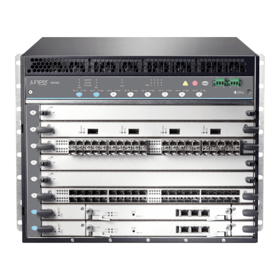
Page 38: Figure 1: Front View Of A Fully Configured Router Chassis
MX480 3D Universal Edge Router Hardware Guide Figure 1: Front View of a Fully Configured Router Chassis Figure 2: Rear View of a Fully Configured AC-Powered Router Chassis Copyright © 2011, Juniper Networks, Inc. -
Page 39: Mx480 Midplane Description
MX480 Router Description on page 3 Documentation MX480 Midplane Description on page 9 MX480 Router Physical Specifications on page 265 MX480 Midplane Description The midplane is located toward the rear of the chassis and forms the rear of the card... -
Page 40: Mx480 Dense Port Concentrator (Dpc) Overview
MX480 Router Description on page 3 Documentation MX480 Chassis Description on page 7 MX480 Dense Port Concentrator (DPC) Description on page 10 MX480 Modular Port Concentrator (MPC) Description on page 13 MX480 Switch Control Board (SCB) Description on page 21... -
Page 41: Figure 5: Typical Dpcs Supported On The Router
Forwarding Engines housed on the DPC are enabled. Forwarding on other DPCs continues uninterrupted during this process. Figure 5 on page 11 shows typical DPCs supported on the MX480 router. For more information about DPCs, see the MX Series 3D Universal Edge Routers Line Card Guide... -
Page 42: Dpc Components
Related MX480 Dense Port Concentrator (DPC) LEDs on page 12 Documentation DPC and MPC LEDs on the MX480 Craft Interface on page 30 Replacing an MX480 DPC on page 182 MX480 Dense Port Concentrator (DPC) LEDs Two LEDs, located on the craft interface above the DPC, display the status of the DPC... -
Page 43: Mx480 Modular Port Concentrator (Mpc) Overview
MPCs interface with the power supplies and Switch Control Boards (SCBs). You must install redundant SCBs to support full line-rate. The MX480 router supports up to six MPCs. You must install a high-capacity fan tray to use an MPC. For power requirements, see Routers”... -
Page 44: Mpc Components
MX480 3D Universal Edge Router Hardware Guide Figure 7: Typical MPC Supported on the MX Series Router MPC (empty) Figure 8: MPC Installed Horizontally in the MX480 Router MPC Components Each MPC consists of the following components: MPC card carrier, which includes two MIC slots (excludes the fixed configuration MPC). -
Page 45: Mx480 Modular Port Concentrator (Mpc) Leds
MX Series 3D Universal Edge Routers Line Card Guide FAIL . For more information about the line card LEDs on the FAIL “DPC and MPC LEDs on the MX480 Craft Interface” on page Chapter 2: MX480 Hardware Components MX Series 3D Universal... -
Page 46: Mx480 Modular Interface Card (Mic) Leds
MPC. Related MICs Supported by MX Series Routers Documentation MX480 Modular Interface Card (MIC) LEDs on page 16 Maintaining MX480 MICs on page 129 Troubleshooting the MX480 MICs on page 150 Replacing an MX480 MIC on page 200 MX480 Modular Interface Card (MIC) LEDs Each MIC has LEDs located on the faceplate. -
Page 47: Figure 9: Fpc Installed In The Mx480 Router Chassis
Chapter 2: MX480 Hardware Components Figure 9: FPC Installed in the MX480 Router Chassis M X4 80 Figure 10 on page 17 shows the typical FPCs supported on the MX480 router. Figure 10: Typical FPCs Supported on the MX480 Router... -
Page 48: Fpc Components
Two LEDs, located on the craft interface above the FPC, that display the status of the FPC and are labeled FPC online/offline button, located on the craft interface above the FPC Related MX480 Flexible PIC Concentrator (FPC) LEDs on page 18 Documentation Maintaining MX480 FPCs on page 125 MX480 FPC Terminology on page 135... -
Page 49: Fpcs Supported By The Mx480 Router
PICs are hot-removable and hot-insertable. Up to two PICs can be installed in the slots in each FPC. Up to three FPCs can be installed in an MX480 router. PICs used in a Type 2 FPC have captive screws at their upper and lower corners. PICs used in a Type 3 FPC have an upper ejector handle and a lower captive screw. -
Page 50: Mx480 Pic Leds
MX480 Host Subsystem LEDs on page 20 Documentation Maintaining the MX480 Host Subsystem on page 120 Taking an MX480 Host Subsystem Offline on page 164 MX480 Host Subsystem LEDs Each host subsystem has three LEDs that display its status. The host subsystem LEDs are located on the upper left of the craft interface. -
Page 51: Mx480 Switch Control Board (Scb) Overview
MX480 Switch Control Board (SCB) Overview MX480 Switch Control Board (SCB) Description on page 21 MX480 Switch Control Board (SCB) LEDs on page 22 MX480 Switch Control Board (SCB) Description The Switch Control Board (SCB) provides the following functions: Powers on and powers off DPCs, FPCs, and MPCs... -
Page 52: Scb Redundancy
MX480 Host Subsystem Description on page 20 Documentation MX480 Routing Engine Description on page 23 MX480 Switch Control Board (SCB) LEDs on page 22 MX480 Switch Control Board (SCB) LEDs Three LEDs on the SCB indicate the status of the SCB. The LEDs, labeled FABRIC ONLY the functions of the SCB LEDs. -
Page 53: Mx480 Routing Engine Overview
SCB LEDs on the craft interface, see on page Related MX480 Switch Control Board (SCB) Description on page 21 Documentation MX480 Host Subsystem Description on page 20 Replacing an MX480 SCB on page 166 MX480 Routing Engine Overview... -
Page 54: Routing Engine Components
MX480 3D Universal Edge Router Hardware Guide Figure 12: Routing Engine Routing Engine Components Routing Engine Interface Ports Three ports, located on the right side of the routing engine, connect the Routing Engine to one or more external devices on which system administrators can issue Junos OS command-line interface (CLI) commands to manage the router. -
Page 55: Re-S-1800 Routing Engine Description For Mx Series
Documentation MX480 Routing Engine LEDs on page 27 MX480 Host Subsystem Description on page 20 MX480 Switch Control Board (SCB) Description on page 21 RE-S-1800 Routing Engine Description for MX Series Figure 13 on page 25 Figure 13: RE-S-1800 Front View... -
Page 56: Re-S-1800 Routing Engine Boot Sequence
MX480 3D Universal Edge Router Hardware Guide Auxiliary port Extractor clip Each Routing Engine consists of the following components: CPU—Runs Junos OS to maintain the router's routing tables and routing protocols.. DRAM—Provides storage for the routing and forwarding tables and for other Routing Engine processes. -
Page 57: Re-S-1800 Routing Engine Leds
ONLINE OK/FAIL Related MX240 Routing Engine Description Documentation MX480 Routing Engine Description on page 23 MX960 Routing Engine Description MX480 Routing Engine LEDs Each Routing Engine has four LEDs that indicate its status. The LEDs, labeled ONLINE 6 on page 27... -
Page 58: Alarm Leds And Alarm Cutoff/Lamp Test Button On The Mx480 Craft
LEDs for the router components, the alarm relay contacts, and alarm cutoff button. Figure 15: Front Panel of the Craft Interface Related Alarm LEDs and Alarm Cutoff/Lamp Test Button on the MX480 Craft Interface on Documentation page 29 Color... -
Page 59: Mx480 Component Leds On The Craft Interface
MX480 Component LEDs on the Craft Interface on page 29 Alarm Relay Contacts on the MX480 Craft Interface on page 32 Alarm LEDs and Alarm Cutoff/Lamp Test Button on the MX480 Craft Interface Two large alarm LEDs are located at the upper right of the craft interface. The circular red LED lights to indicate a critical condition that can result in a system shutdown. -
Page 60: Host Subsystem Leds On The Mx480 Craft Interface
MX480 3D Universal Edge Router Hardware Guide SCB LEDs on the MX480 Craft Interface on page 31 Fan LEDs on the MX480 Craft Interface on page 31 Host Subsystem LEDs on the MX480 Craft Interface Each host subsystem has three LEDs, located on the upper left of the craft interface, that indicate its status. -
Page 61: Fpc Leds On The Mx480 Craft Interface
Table 10: DPC and MPC LEDs on the Craft Interface (continued) Label FAIL FPC LEDs on the MX480 Craft Interface An FPC takes up two DPC slots when installed in an MX Series router. The LEDs, labeled through to the lowest DPC slot number in which the FPC is installed. -
Page 62: Alarm Relay Contacts On The Mx480 Craft Interface
MX480 DC Power Supply LEDs on page 37 MX480 Power System Description The MX480 router uses either AC or DC power supplies. The MX480 router is configurable with two, three, or four AC power supplies or two or four DC power supplies. The power... -
Page 63: Mx480 Ac Power Supply Description
MX480 DC Power Supply Description on page 36 Connecting Power to an AC-Powered MX480 Router with Normal-Capacity Power Supplies on page 97 Connecting Power to a DC-Powered MX480 Router with Normal Capacity Power Supplies on page 100 Replacing an MX480 AC Power Supply on page 212... -
Page 64: Ac Power Supply Configurations
Edge Router Hardware Guide AC Power Supply Configurations The MX480 router supports either the low-line (110 V) AC power configuration or the high-line (220 V) AC power configuration. In the low-line (110 V) AC power configuration, the MX480 router contains three or... -
Page 65: Mx480 Ac Power Supply Leds
With high-capacity power supplies, you must have a minimum of three power supplies installed in the router. In the high-line (220 V) AC power configuration, the MX480 router contains two or four AC power supplies (see the chassis in slots configuration, each AC power supply provides power to all components in the router. -
Page 66: Mx480 Dc Power Supply Description
DIP switch setting. Figure 19: DC Power Supply Figure 20: High-Capacity DC Power Supply DC Power Supply Configurations In the DC power configuration, the MX480 router contains either two or four DC power supplies (see through PEM3 power supplies. -
Page 67: Mx480 Dc Power Supply Leds
MX480 AC Power Supply Description on page 33 MX480 DC Power Supply LEDs on page 37 DC Power Supply Electrical Specifications for the MX480 Router on page 280 MX480 DC Power Supply LEDs Each DC power supply faceplate contains three LEDs that indicate the status of the power supply (see LEDs on the craft interface.In addition, a power supply failure triggers the red alarm LED... -
Page 68: Mx480 Cooling System Overview
MX480 Power System Description on page 32 MX480 AC Power Supply Description on page 33 MX480 DC Power Supply Description on page 36 DC Power Supply Electrical Specifications for the MX480 Router on page 280 MX480 Cooling System Overview MX480 Cooling System Description on page 38... -
Page 69: Figure 21: Airflow Through The Chassis
Chapter 2: MX480 Hardware Components above the craft interface. The exhaust for the power supplies is located on the rear bulkhead power supplies. Figure 21: Airflow Through the Chassis The host subsystem monitors the temperature of the router components. When the router is operating normally, the fans function at lower than full speed. -
Page 70: Mx480 Fan Led
Figure 23: Air Filter Related MX480 Fan LED on page 40 Documentation Maintaining the MX480 Air Filter on page 116 Maintaining the MX480 Fan Tray on page 116 Troubleshooting the MX480 Cooling System on page 144 MX480 Fan LED Each fan has an LED that displays its status. The fan LEDs are located on the top left of the craft interface. -
Page 71: Figure 24: Cable Management Brackets
Figure 24: Cable Management Brackets Figure 25: Cable Management Brackets Installed on the Router Related Maintaining Cables That Connect to MX480 DPCs, MPCs, MICs, or PICs on page 130 Documentation Replacing the MX480 Cable Management Brackets on page 223 Copyright © 2011, Juniper Networks, Inc. - Page 72 MX480 3D Universal Edge Router Hardware Guide Copyright © 2011, Juniper Networks, Inc.
-
Page 73: Setting Up The Mx480 Router
Unpacking the MX480 Router on page 53 Installing the MX480 Router Mounting Hardware on page 57 Installing the MX480 Router with a Mechanical Lift on page 61 Installing the MX480 Router Without a Mechanical Lift on page 75 Connecting the MX480 Router on page 89... - Page 74 MX480 3D Universal Edge Router Hardware Guide Copyright © 2011, Juniper Networks, Inc.
-
Page 75: Chapter 3 Preparing The Site For Mx480 Router Installation
Preparing the Site for MX480 Router Installation MX480 Site Preparation Checklist on page 45 MX480 Router Rack Requirements on page 46 MX480 Router Clearance Requirements for Airflow and Hardware Maintenance on page 48 MX480 Router Cabinet Requirements on page 49 MX480 Site Preparation Checklist The checklist in preparing a site for router installation. -
Page 76: Mx480 Router Rack Requirements
Related MX480 Router Rack Requirements on page 46 Documentation MX480 Router Clearance Requirements for Airflow and Hardware Maintenance on page 48 MX480 Router Cabinet Size and Clearance Requirements on page 49 MX480 Router Rack Requirements The router can be installed in a rack. Many types of racks are acceptable, including four-post (telco) racks and open-frame racks. -
Page 77: Spacing Of Mounting Bracket Holes
Cabinets, Racks, Panels, and Associated Equipment (document number EIA-310-D) published by the Electronics Industry Association. You can stack five MX480 routers in a rack that has at least 48 U (84 in. or 2.13 m) of usable vertical space. -
Page 78: Connection To Building Structure
MX480 Site Preparation Checklist on page 45 Documentation Installation Safety Warnings for Juniper Networks Hardware Equipment on page 235 MX480 Router Clearance Requirements for Airflow and Hardware Maintenance When planning the installation site, you need to allow sufficient clearance around the... -
Page 79: Mx480 Router Cabinet Requirements
Related MX480 Site Preparation Checklist on page 45 Documentation Installation Safety Warnings for Juniper Networks Hardware Equipment on page 235 MX480 Router Cabinet Requirements MX480 Router Cabinet Size and Clearance Requirements on page 49 MX480 Router Cabinet Airflow Requirements on page 50... -
Page 80: Mx480 Router Cabinet Airflow Requirements
Route and dress all cables to minimize the blockage of airflow to and from the chassis. Figure 28: Airflow Through the Chassis Related MX480 Site Preparation Checklist on page 45 Documentation Installation Safety Warnings for Juniper Networks Hardware Equipment on page 235 Figure 28 Copyright © 2011, Juniper Networks, Inc. -
Page 81: Mx480 Router Installation Overview
General Safety Warnings for Juniper Networks Hardware Equipment on page 230 Unpack the router and verify that all parts have been received. Install the mounting hardware. “Installing the MX480 Router Mounting Hardware for a Rack or Cabinet” on page Install the router. - Page 82 Powering On a DC-Powered MX480 Router on page 105 Perform the initial system configuration. “Initially Configuring the MX480 Router” on page Related Tools and Parts Required to Unpack the MX480 Router on page 53 Documentation 109. Copyright © 2011, Juniper Networks, Inc.
-
Page 83: Unpacking The Mx480 Router
CHAPTER 5 Unpacking the MX480 Router Tools and Parts Required to Unpack the MX480 Router on page 53 Unpacking the MX480 Router on page 53 Verifying the MX480 Router Parts Received on page 55 Tools and Parts Required to Unpack the MX480 Router... -
Page 84: Figure 29: Contents Of The Shipping Crate
Verifying the MX480 Router Parts Received on page 55 Documentation Installing the MX480 Router Mounting Hardware for a Rack or Cabinet on page 57 Installing the MX480 Router Using a Mechanical Lift on page 66 Tools Required to Install the MX480 Router with a Mechanical Lift... -
Page 85: Verifying The Mx480 Router Parts Received
Verifying the MX480 Router Parts Received A packing list is included in each shipment. Check the parts in the shipment against the items on the packing list. The packing list specifies the part numbers and descriptions of each part in your order. -
Page 86: Table 19: Accessory Box Parts List
Ethernet cable, RJ-45/RJ-45, 4-pair stranded UTP, Category 5E, 15' ESD wrist strap with cable Related Tools and Parts Required to Unpack the MX480 Router on page 53 Documentation Unpacking the MX480 Router on page 53 Quantity Copyright © 2011, Juniper Networks, Inc. -
Page 87: Installing The Mx480 Router Mounting Hardware
Installing the MX480 Router Mounting Hardware Installing the MX480 Router Mounting Hardware for a Rack or Cabinet on page 57 Moving the Mounting Brackets for Center-Mounting the MX480 Router on page 59 Installing the MX480 Router Mounting Hardware for a Rack or Cabinet The router can be installed in a four-post rack or cabinet or an open-frame rack. -
Page 88: Figure 30: Installing The Front Mounting Hardware For A Four-Post Rack Or
MX480 3D Universal Edge Router Hardware Guide Install the mounting shelf on the back of the rack rails. Rest the bottom slot of each flange on a mounting screw. Partially insert the remaining screws into the open holes in each flange of the mounting shelf (see Tighten all the screws completely. -
Page 89: Moving The Mounting Brackets For Center-Mounting The Mx480 Router
Installing the MX480 Router Using a Mechanical Lift on page 66 Documentation Tools Required to Install the MX480 Router Without a Mechanical Lift on page 75 Moving the Mounting Brackets for Center-Mounting the MX480 Router Two removable mounting brackets are attached to the mounting holes closest to the front of the chassis. - Page 90 Repeat the procedure for the other bracket. Related Installing the MX480 Router Using a Mechanical Lift on page 66 Documentation Tools Required to Install the MX480 Router Without a Mechanical Lift on page 75 Copyright © 2011, Juniper Networks, Inc.
-
Page 91: Installing The Mx480 Router With A Mechanical Lift
Tools Required to Install the MX480 Router with a Mechanical Lift on page 61 Removing Components from the MX480 Router Before Installing It with a Lift on page 61 Installing the MX480 Router Using a Mechanical Lift on page 66... -
Page 92: Lift
Removing the Power Supplies Before Installing the MX480 Router with a Lift on page 62 Removing the Fan Tray Before Installing the MX480 Router with a Lift on page 63 Removing the SCBs Before Installing the MX480 Router with a Lift on page 63... -
Page 93: Removing The Fan Tray Before Installing The Mx480 Router With A Lift
Removing the Fan Tray Before Installing the MX480 Router with a Lift To remove the fan tray (see Attach an electrostatic discharge (ESD) grounding strap to your bare wrist, and connect the strap to an approved site ESD grounding point. See the instructions for your site. -
Page 94: Removing The Dpcs Before Installing The Mx480 Router With A Lift
Repeat the procedure for each SCB. Figure 34: Removing an SCB Removing the DPCs Before Installing the MX480 Router with a Lift To remove a DPC (see Have ready an antistatic mat for the DPC. Also have ready rubber safety caps for each DPC using an optical interface on the DPC that you are removing. -
Page 95: Removing The Fpcs Before Installing The Mx480 Router With A Lift
Figure 35: Removing a DPC Removing the FPCs Before Installing the MX480 Router with a Lift To remove an FPC (see Have ready an antistatic mat for the FPC. Also have ready rubber safety caps for each PIC using an optical interface on the PIC that you are removing. -
Page 96: Installing The Mx480 Router Using A Mechanical Lift
Tools Required to Install the MX480 Router with a Mechanical Lift on page 61 Installing the MX480 Router Using a Mechanical Lift on page 66 Reinstalling Components in the MX480 Router After Installing It with a Lift on page 68 Installing the MX480 Router Using a Mechanical Lift Because of the router's size and weight—up to 163.5 lb (74.2 kg) depending on the... -
Page 97: Figure 37: Installing The Router In The Rack
Figure 37: Installing the Router in the Rack Related MX480 Site Preparation Checklist on page 45 Documentation Preventing Electrostatic Discharge Damage to an MX480 Router on page 232 Copyright © 2011, Juniper Networks, Inc. Chapter 7: Installing the MX480 Router with a Mechanical Lift NOTE: This illustration depicts the router being installed in an open-frame rack. -
Page 98: Reinstalling Components In The Mx480 Router After Installing It With A Lift
Removing Components from the MX480 Router Before Installing It with a Lift on page 61 Reinstalling Components in the MX480 Router After Installing It with a Lift on page 68 Reinstalling Components in the MX480 Router After Installing It with a Lift After the router is installed in the rack, you reinstall the removed components before booting and configuring the router. -
Page 99: Reinstalling The Fan Tray After Installing The Mx480 Router With A Lift
Figure 38: Reinstalling a Power Supply Reinstalling the Fan Tray After Installing the MX480 Router with a Lift To reinstall the fan tray (see Attach an electrostatic discharge (ESD) grounding strap to your bare wrist, and connect the strap to one of the ESD points on the chassis. -
Page 100: Reinstalling The Scbs After Installing The Mx480 Router With A Lift
MX480 3D Universal Edge Router Hardware Guide Figure 39: Reinstalling a Fan Tray Reinstalling the SCBs After Installing the MX480 Router with a Lift To reinstall an SCB (see Attach an electrostatic discharge (ESD) grounding strap to your bare wrist, and connect the strap to one of the ESD points on the chassis. -
Page 101: Reinstalling The Dpcs After Installing The Mx480 Router With A Lift
Figure 40: Reinstalling an SCB Reinstalling the DPCs After Installing the MX480 Router with a Lift To reinstall a DPC (see Attach an electrostatic discharge (ESD) grounding strap to your bare wrist, and connect the strap to one of the ESD points on the chassis. -
Page 102: Reinstalling The Fpcs After Installing The Mx480 Router With A Lift
MX480 3D Universal Edge Router Hardware Guide Figure 41: Reinstalling a DPC Reinstalling the FPCs After Installing the MX480 Router with a Lift To reinstall an FPC (see Attach an electrostatic discharge (ESD) grounding strap to your bare wrist, and connect the strap to one of the ESD points on the chassis. -
Page 103: Installing The Mx480 Router Cable Management Bracket
Preventing Electrostatic Discharge Damage to an MX480 Router on page 232 Documentation Tools Required to Install the MX480 Router with a Mechanical Lift on page 61 Removing Components from the MX480 Router Before Installing It with a Lift on page 61... -
Page 104: Figure 43: Installing The Cable Management Brackets
MX480 3D Universal Edge Router Hardware Guide Figure 43: Installing the Cable Management Brackets Related Preventing Electrostatic Discharge Damage to an MX480 Router on page 232 Documentation Tools and Parts Required for MX480 Router Connections on page 89 Copyright © 2011, Juniper Networks, Inc. -
Page 105: Installing The Mx480 Router Without A Mechanical Lift
CHAPTER 8 Installing the MX480 Router Without a Mechanical Lift Tools Required to Install the MX480 Router Without a Mechanical Lift on page 75 Removing Components from the MX480 Router Before Installing It Without a Lift on page 75 Installing the MX480 Chassis in the Rack Manually on page 81... -
Page 106: Removing The Power Supplies Before Installing The Mx480 Router Without
Removing the Power Supplies Before Installing the MX480 Router Without a Lift on page 76 Removing the Fan Tray Before Installing the MX480 Router Without a Lift on page 77 Removing the SCBs Before Installing the MX480 Router Without a Lift on page 77... -
Page 107: Removing The Scbs Before Installing The Mx480 Router Without A Lift
Removing the Fan Tray Before Installing the MX480 Router Without a Lift To remove the fan tray (see Attach an electrostatic discharge (ESD) grounding strap to your bare wrist, and connect the strap to an approved site ESD grounding point. See the instructions for your site. -
Page 108: Removing The Dpcs Before Installing The Mx480 Router Without A Lift
Repeat the procedure for each SCB. Figure 46: Removing an SCB Removing the DPCs Before Installing the MX480 Router Without a Lift To remove a DPC (see Have ready an antistatic mat for the DPC. Also have ready rubber safety caps for each DPC using an optical interface on the DPC that you are removing. -
Page 109: Removing The Fpcs Before Installing The Mx480 Router Without A Lift
Figure 47: Removing a DPC Removing the FPCs Before Installing the MX480 Router Without a Lift To remove an FPC (see Have ready an antistatic mat for the FPC. Also have ready rubber safety caps for each PIC using an optical interface on the PIC that you are removing. -
Page 110: Figure 48: Removing An Fpc
Preventing Electrostatic Discharge Damage to an MX480 Router on page 232 Documentation Tools Required to Install the MX480 Router Without a Mechanical Lift on page 75 Installing the MX480 Chassis in the Rack Manually on page 81 Reinstalling Components in the MX480 Router After Installing It Without a Lift on... -
Page 111: Installing The Mx480 Chassis In The Rack Manually
Copyright © 2011, Juniper Networks, Inc. Chapter 8: Installing the MX480 Router Without a Mechanical Lift Figure 49 on page CAUTION: If you are installing more than one router in a rack, install the lowest one first. -
Page 112: Figure 49: Installing The Router In The Rack
Related MX480 Site Preparation Checklist on page 45 Documentation Tools Required to Install the MX480 Router Without a Mechanical Lift on page 75 Removing Components from the MX480 Router Before Installing It Without a Lift on page 75 Reinstalling Components in the MX480 Router After Installing It Without a Lift on... -
Page 113: Reinstalling Components In The Mx480 Router After Installing It Without A
Reinstalling the Power Supplies After Installing the MX480 Router Without a Lift on page 83 Reinstalling the Fan Tray After Installing the MX480 Router Without a Lift on page 84 Reinstalling the SCBs After Installing the MX480 Router Without a Lift on page 85... -
Page 114: Lift
MX480 3D Universal Edge Router Hardware Guide Figure 50: Reinstalling a Power Supply Reinstalling the Fan Tray After Installing the MX480 Router Without a Lift To reinstall the fan tray (see Attach an electrostatic discharge (ESD) grounding strap to your bare wrist, and connect the strap to one of the ESD points on the chassis. -
Page 115: Reinstalling The Scbs After Installing The Mx480 Router Without A Lift
Figure 51: Reinstalling a Fan Tray Reinstalling the SCBs After Installing the MX480 Router Without a Lift To reinstall an SCB (see Attach an electrostatic discharge (ESD) grounding strap to your bare wrist, and connect the strap to one of the ESD points on the chassis. -
Page 116: Reinstalling The Dpcs After Installing The Mx480 Router Without A Lift
MX480 3D Universal Edge Router Hardware Guide Figure 52: Reinstalling an SCB Reinstalling the DPCs After Installing the MX480 Router Without a Lift To reinstall a DPC (see Attach an electrostatic discharge (ESD) grounding strap to your bare wrist, and connect the strap to one of the ESD points on the chassis. -
Page 117: Reinstalling The Fpcs After Installing The Mx480 Router Without A Lift
Figure 53: Reinstalling a DPC Reinstalling the FPCs After Installing the MX480 Router Without a Lift To reinstall a DPC (see Attach an electrostatic discharge (ESD) grounding strap to your bare wrist, and connect the strap to one of the ESD points on the chassis. -
Page 118: Figure 54: Reinstalling An Fpc
Preventing Electrostatic Discharge Damage to an MX480 Router on page 232 Documentation Tools Required to Install the MX480 Router Without a Mechanical Lift on page 75 Removing Components from the MX480 Router Before Installing It Without a Lift on page 75... -
Page 119: Connecting The Mx480 Router To A Management Console Or Auxiliary
Tools and Parts Required for MX480 Router Connections on page 89 Connecting the MX480 Router to Management and Alarm Devices on page 89 Connecting DPC, MPC, MIC, or PIC Cables to the MX480 Router on page 92 Tools and Parts Required for MX480 Router Connections... -
Page 120: Device
Plug the other end of the cable into the network device. Figure 55: Ethernet Port Figure 56: Routing Engine Ethernet Cable Connector Connecting the MX480 Router to a Management Console or Auxiliary Device To use a system console to configure and manage the Routing Engine, connect it to the appropriate auxiliary device, connect it to the cable with an RJ-45 connector. -
Page 121: Connecting The Mx480 Router To An External Alarm-Reporting Device
Figure 57: Auxiliary and Console Ports Figure 58: Routing Engine Console and Auxiliary Cable Connector Connecting the MX480 Router to an External Alarm-Reporting Device To connect the router to external alarm-reporting devices, attach wires to the relay contacts on the craft interface. (See... -
Page 122: Connecting Dpc, Mpc, Mic, Or Pic Cables To The Mx480 Router
MX480 3D Universal Edge Router Hardware Guide Related Tools and Parts Required for MX480 Router Connections on page 89 Documentation Routing Engine Interface Cable and Wire Specifications for MX Series Routers on page 288 Connecting DPC, MPC, MIC, or PIC Cables to the MX480 Router... -
Page 123: Figure 60: Attaching A Cable To A Dpc
Chapter 9: Connecting the MX480 Router Figure 60: Attaching a Cable to a DPC Figure 61: Attaching a Cable to a MIC Fiber-optic cable Related Tools and Parts Required for MX480 Router Connections on page 89 Documentation Copyright © 2011, Juniper Networks, Inc. - Page 124 MX480 3D Universal Edge Router Hardware Guide Copyright © 2011, Juniper Networks, Inc.
-
Page 125: Grounding And Providing Power To The Mx480 Router
Installing the MX480 AC High-Capacity Power Supplies on page 98 Powering On an AC-Powered MX480 Router on page 99 Connecting Power to a DC-Powered MX480 Router with Normal Capacity Power Supplies on page 100 Installing an MX480 DC High-Capacity Power Supply on page 103... -
Page 126: Connecting Power To An Ac-Powered Mx480 Router With Normal-Capacity
MX480 Chassis Grounding Specifications on page 273 Connecting Power to an AC-Powered MX480 Router with Normal-Capacity Power Supplies on page 97 Connecting Power to a DC-Powered MX480 Router with Normal Capacity Power Supplies on page 100 Grounding the MX480 Router You ground the router by connecting a grounding cable to earth ground and then attaching it to the chassis grounding points using UNC 1/4-20 two screws. -
Page 127: Power Supplies
Connecting Power to an AC-Powered MX480 Router with Normal-Capacity Power Supplies You connect AC power to the router by attaching power cords from the AC power sources to the AC appliance inlets located on the power supplies. For power cord and AC power... -
Page 128: Installing The Mx480 Ac High-Capacity Power Supplies
MX480 3D Universal Edge Router Hardware Guide Figure 62: Connecting AC Power to the Router (110V) Related Preventing Electrostatic Discharge Damage to an MX480 Router on page 232 Documentation Installing the MX480 AC High-Capacity Power Supplies To install a high-capacity AC power supply: Move the AC input switch next to the appliance inlet on the power supply to the off ( position. -
Page 129: Powering On An Ac-Powered Mx480 Router
If any of the status LEDs indicates that the power supply is not functioning normally, repeat the installation and cabling procedures. Copyright © 2011, Juniper Networks, Inc. Chapter 10: Grounding and Providing Power to the MX480 Router , or CONSOLE... -
Page 130: Supplies
Preventing Electrostatic Discharge Damage to an MX480 Router on page 232 Documentation Connecting the MX480 Router to Management and Alarm Devices on page 89 Replacing an MX480 AC Power Supply on page 212 Connecting Power to a DC-Powered MX480 Router with Normal Capacity Power... - Page 131 Secure each positive (+) DC source power cable lug to the b. Secure each negative (–) DC source power cable lug to the Copyright © 2011, Juniper Networks, Inc. Chapter 10: Grounding and Providing Power to the MX480 Router DC cables to chassis ground: CAUTION: You must ensure that power connections maintain the proper polarity.
-
Page 132: Figure 64: Connecting Dc Power To The Router
Repeat Steps Figure 64: Connecting DC Power to the Router Related DC Power Cable Specifications for the MX480 Router on page 282 Documentation Preventing Electrostatic Discharge Damage to an MX480 Router on page 232 CAUTION: The maximum torque rating of the terminal studs on the DC power supply is 36 lb-in. -
Page 133: Installing An Mx480 Dc High-Capacity Power Supply
Secure the positive (+) DC source power cable lug to the b. Secure the negative (–) DC source power cable lug to the Copyright © 2011, Juniper Networks, Inc. Chapter 10: Grounding and Providing Power to the MX480 Router Figure 111 on page 218):... - Page 134 MX480 3D Universal Edge Router Hardware Guide Replace the clear plastic cover over the terminal studs on the faceplate. Route the power cables along the cable restraint toward the left or right corner of the chassis. If needed to hold the power cables in place, thread plastic cable ties, which you must provide, through the openings on the cable restraint.
-
Page 135: Powering On A Dc-Powered Mx480 Router
On each of the DC power supplies, switch the DC circuit breaker to the center position before moving it to the on ( Copyright © 2011, Juniper Networks, Inc. Chapter 10: Grounding and Providing Power to the MX480 Router CONSOLE , or ETHERNET LED is lit steadily green to verify that power is present. - Page 136 On the external management device connected to the Routing Engine, monitor the startup process to verify that the system has booted properly. Related Connecting the MX480 Router to Management and Alarm Devices on page 89 Documentation Preventing Electrostatic Discharge Damage to an MX480 Router on page 232...
-
Page 137: Powering Off The Mx480 Router
Move the AC input switch on each AC power supply or the DC circuit breaker on each DC power supply to the off ( Related Preventing Electrostatic Discharge Damage to an MX480 Router on page 232 Documentation Copyright © 2011, Juniper Networks, Inc. - Page 138 MX480 3D Universal Edge Router Hardware Guide Copyright © 2011, Juniper Networks, Inc.
-
Page 139: Chapter 11 Configuring Junos Os
The MX480 router is shipped with the Junos OS preinstalled and ready to be configured when the MX480 router is powered on. There are three copies of the software: one on a CompactFlash card in the Routing Engine, one on a rotating hard disk in the Routing Engine, and one on a USB flash drive that can be inserted into the slot in the Routing Engine faceplate. - Page 140 MX480 3D Universal Edge Router Hardware Guide Start the CLI. root# cli root@> Enter configuration mode. cli> configure [edit] root@# Configure the name of the router. If the name includes spaces, enclose the name in quotation marks (“ ”). [edit] root@# set system host-name host-name Create a management console user account.
- Page 141 Then commit the changes to activate them on the router. [edit] root@host# commit When you have finished configuring the router, exit configuration mode. Copyright © 2011, Juniper Networks, Inc. family inet { address address/prefix-length; Chapter 11: Configuring Junos OS...
- Page 142 If the router boots from an alternate boot device, the Junos OS displays a message indication this when you log in to the router. Related Powering On an AC-Powered MX480 Router on page 99 Documentation Powering On a DC-Powered MX480 Router on page 105...
-
Page 143: Hardware Maintenance, Troubleshooting, And Replacement Procedures
PART 3 Hardware Maintenance, Troubleshooting, and Replacement Procedures Maintaining MX480 Router Hardware Components on page 115 Troubleshooting MX480 Hardware Components on page 141 Replacing MX480 Hardware Components on page 153 Copyright © 2011, Juniper Networks, Inc. - Page 144 MX480 3D Universal Edge Router Hardware Guide Copyright © 2011, Juniper Networks, Inc.
-
Page 145: Maintaining Mx480 Router Hardware Components
This chapter describes how to maintain hardware components installed in the router. Some components, such as the craft interface, require no maintenance. For information about returning a part to Juniper Networks for repair or replacement, see “Contacting Customer Support and Returning MX480 Hardware” on page... -
Page 146: Maintaining The Mx480 Cooling System Components
Related Replacing the MX480 Air Filter on page 155 Documentation Routine Maintenance Procedures for the MX480 Router on page 115 Maintaining the MX480 Fan Tray Purpose For optimum cooling, verify the condition of the fans. - Page 147 F degrees F degrees F degrees F degrees F degrees F Copyright © 2011, Juniper Networks, Inc. Chapter 12: Maintaining MX480 Router Hardware Components Temp PEM 0 PEM 1 PEM 2 PEM 3 Routing Engine 0 Routing Engine 0 CPU...
- Page 148 MX480 3D Universal Edge Router Hardware Guide degrees F degrees F degrees F degrees F degrees F degrees F degrees F degrees F degrees F degrees F degrees F degrees F degrees F degrees F degrees F degrees F degrees F...
- Page 149 F degrees F degrees F degrees F Copyright © 2011, Juniper Networks, Inc. Chapter 12: Maintaining MX480 Router Hardware Components FPC 3 IA 0 Chip FPC 3 IA 1 TSensor FPC 3 IA 1 Chip FPC 4 Intake FPC 4 Exhaust A...
-
Page 150: Maintaining The Mx480 Host Subsystem
Related Routine Maintenance Procedures for the MX480 Router on page 115 Documentation Installing the MX480 Fan Tray on page 161 Maintaining the MX480 Host Subsystem Purpose For optimum router performance, verify the condition of the host subsystem. The host subsystem comprises an SCB and a Routing Engine installed directly into an SCB. - Page 151 To check the status of the SCBs, issue the The output is similar to the following: user@host> show chassis environment cb CB 0 status: CB 1 status: Copyright © 2011, Juniper Networks, Inc. Chapter 12: Maintaining MX480 Router Hardware Components CPU utilization: User 0 percent Background 0 percent...
-
Page 152: Maintaining Mx480 Packet Forwarding Engine Components
MX480 3D Universal Edge Router Hardware Guide To check the status of a specific SCB, issue the and include the slot number of the SCB. The output is similar to the following: user@host> show chassis environment cb 0 CB 0 status:... -
Page 153: Maintaining Mx480 Dpcs
Maintaining MX480 MICs on page 129 Maintaining Cables That Connect to MX480 DPCs, MPCs, MICs, or PICs on page 130 Holding and Storing MX Series DPCs on page 131 Holding and Storing MX Series FPCs on page 135 Maintaining MX480 DPCs... - Page 154 For further description of the output from the command, see the and Services Command Reference Related MX480 Chassis Description on page 7 Documentation DPC and MPC LEDs on the MX480 Craft Interface on page 30 Total CPU DRAM Total RLDRAM Total DDR DRAM Start time:...
-
Page 155: Maintaining Mx480 Fpcs
Maintaining MX480 FPCs Purpose The MX480 router can have up to three Flexible PIC Concentrators (FPCs) installed horizontally in the front of the chassis. For optimum router performance, verify the condition of the FPC. Action On a regular basis: Check the LEDs on the craft interface directly above the FPC. The green LED labeled lights steadily when an FPC is functioning normally. -
Page 156: Maintaining Mx480 Pics
For further description of the output from the command, see the and Services Command Reference Related MX480 Flexible PIC Concentrator (FPC) LEDs on page 18 Documentation Replacing an MX480 FPC on page 186 Holding an MX480 FPC on page 136... -
Page 157: Maintaining Mx480 Mpcs
For further description of the output from the command, see the and Services Command Reference Related MX480 Flexible PIC Concentrator (FPC) Description on page 16 Documentation Replacing an MX480 PIC on page 191 Troubleshooting the MX480 PICs on page 148... - Page 158 MX480 3D Universal Edge Router Hardware Guide Issue the CLI shown in the sample output, the value that the MPC is functioning normally: user@host> show chassis fpc Slot State For more detailed output, add the a slot number, which is optional: user@host>...
-
Page 159: Maintaining Mx480 Mics
For further description of the output from the command, see the and Services Command Reference Related MX480 Modular Port Concentrator (MPC) Description on page 13 Documentation MX480 Modular Port Concentrator (MPC) LEDs on page 15 Troubleshooting the MX480 MPCs on page 148... -
Page 160: Maintaining Cables That Connect To Mx480 Dpcs, Mpcs, Mics, Or Pics
Troubleshooting the MX480 MICs on page 150 Replacing an MX480 MIC on page 200 Maintaining Cables That Connect to MX480 DPCs, MPCs, MICs, or PICs Purpose For optimum router performance, verify the condition of the cables that connect to the DPCs, MPCs, MICs, or PICs. -
Page 161: Holding And Storing Mx Series Dpcs
Maintaining MX480 PICs on page 126 Holding and Storing MX Series DPCs MX480 DPC Terminology on page 132 Holding an MX480 DPC on page 132 Storing an MX480 DPC on page 134 Copyright © 2011, Juniper Networks, Inc. Chapter 12: Maintaining MX480 Router Hardware Components... -
Page 162: Mx480 Dpc Terminology
Related Holding an MX480 DPC on page 132 Documentation Installing a Cable on an MX480 DPC, MPC, MIC, or PIC on page 208 Maintaining MX480 DPCs on page 123 Holding an MX480 DPC When carrying a DPC, you can hold it either vertically or horizontally. -
Page 163: Figure 68: Do Not Grasp The Connector Edge
Never carry the DPC by the faceplate with only one hand. Do not rest any edge of a DPC directly against a hard surface (see Do not stack DPCs. Copyright © 2011, Juniper Networks, Inc. Chapter 12: Maintaining MX480 Router Hardware Components Figure 69 on page 134). -
Page 164: Storing An Mx480 Dpc
MX480 3D Universal Edge Router Hardware Guide Figure 69: Do Not Rest the DPC on an Edge If you must rest the DPC temporarily on an edge while changing its orientation between vertical and horizontal, use your hand as a cushion between the edge and the surface. -
Page 165: Holding And Storing Mx Series Fpcs
Bottom edge—Edge at the bottom of the FPC when it is vertical Figure 70: FPC Edges Faceplate Related MX480 Flexible PIC Concentrator (FPC) Description on page 16 Documentation Holding an MX480 FPC on page 136 Copyright © 2011, Juniper Networks, Inc. -
Page 166: Holding An Mx480 Fpc
MX480 3D Universal Edge Router Hardware Guide Storing an MX480 FPC on page 138 Holding an MX480 FPC Figure 71: Do Not Grasp the Connector Edge CAUTION: Many components on the FPC are fragile. Failure to handle FPCs as specified in this document can cause irreparable damage. -
Page 167: Figure 72: Do Not Carry An Fpc With Only One Hand
Chapter 12: Maintaining MX480 Router Hardware Components Figure 72: Do Not Carry an FPC with Only One Hand Do not rest any edge of an FPC directly against a hard surface (see Figure 73 on page 138). If you must rest the FPC temporarily on an edge while changing its orientation between vertical and horizontal, use your hand as a cushion between the edge and the surface. -
Page 168: Storing An Mx480 Fpc
Orient the FPC so that the faceplate faces you. Grasp the top edge with your left hand and the bottom edge with your right hand. Related MX480 Flexible PIC Concentrator (FPC) Description on page 16 Documentation MX480 FPC Terminology on page 135... -
Page 169: Maintaining The Mx480 Power Supplies
Figure 74: Do Not Stack FPCs Related MX480 Flexible PIC Concentrator (FPC) Description on page 16 Documentation MX480 FPC Terminology on page 135 Holding an MX480 FPC on page 136 Maintaining the MX480 Power Supplies Purpose For optimum router performance, verify the condition of the power supplies. - Page 170 Related Power Supply LEDs on the MX480 Craft Interface on page 30 Documentation MX480 AC Power Supply Description on page 33 MX480 DC Power Supply Description on page 36...
-
Page 171: Troubleshooting Mx480 Hardware Components
CHAPTER 13 Troubleshooting MX480 Hardware Components Troubleshooting Resources for MX480 Routers on page 141 Troubleshooting the MX480 Cooling System on page 144 Troubleshooting the MX480 DPCs on page 144 Troubleshooting the MX480 FPCs on page 146 Troubleshooting the MX480 PICs on page 148... -
Page 172: Chassis And Interface Alarm Messages
MX480 3D Universal Edge Router Hardware Guide Chassis and Interface Alarm Messages When the Routing Engine detects an alarm condition, it lights the red or yellow alarm LED on the craft interface as appropriate. To view a more detailed description of the alarm cause, issue the user@host>... -
Page 173: Component Leds
Power supply LEDs—Two LEDs on each power supply faceplate indicate the status of that power supply. Juniper Networks Technical Assistance Center If you need assistance during troubleshooting, you can contact the Juniper Networks Technical Assistance Center (JTAC) by using the Web or by telephone. Related... -
Page 174: Troubleshooting The Mx480 Cooling System
The temperature of the router exceeds the maximum (“temperature hot”) threshold (red alarm and automatic shutdown of the power supplies). Related Alarm LEDs and Alarm Cutoff/Lamp Test Button on the MX480 Craft Interface on Documentation page 29 Replacing the MX480 Fan Tray on page 160... - Page 175 Slot 0 information: Slot 1 information: Slot 2 information: Copyright © 2011, Juniper Networks, Inc. Chapter 13: Troubleshooting MX480 Hardware Components LED on the DPC and OK/FAIL show chassis fpc command to check the status of installed DPCs. As shown...
-
Page 176: Troubleshooting The Mx480 Fpcs
MX480 3D Universal Edge Router Hardware Guide Slot 5 information: For further description of the output from the commands, see the Basics Configuration Guide Related Installing an MX480 DPC on page 184 Documentation MX480 DPC Terminology on page 132 Maintaining MX480 DPCs on page 123... - Page 177 Slot 4 information: For further description of the output from the commands, see the Basics Configuration Guide Related MX480 Flexible PIC Concentrator (FPC) LEDs on page 18 Documentation Replacing an MX480 FPC on page 186 Holding an MX480 FPC on page 136...
-
Page 178: Troubleshooting The Mx480 Pics
Slot 4 For further description of the output from the command, see the and Services Command Reference Related MX480 Flexible PIC Concentrator (FPC) Description on page 16 Documentation Replacing an MX480 PIC on page 191 Maintaining MX480 PICs on page 126... - Page 179 Slot 1 information: Copyright © 2011, Juniper Networks, Inc. Chapter 13: Troubleshooting MX480 Hardware Components above the MPC on the craft interface as soon as an LED blinks. When the MPC is online and functioning LED lights green steadily.
-
Page 180: Troubleshooting The Mx480 Mics
For further description of the output from the commands, see the Basics Configuration Guide Related MX480 Modular Port Concentrator (MPC) Description on page 13 Documentation Maintaining MX480 MPCs on page 127 Replacing an MX480 MPC on page 195 Troubleshooting the MX480 MICs Problem The MICs are not functioning normally. -
Page 181: Troubleshooting The Mx480 Power System
Slot 4 For further description of the output from the command, see the and Services Command Reference Related MX480 Modular Interface Card (MIC) Description on page 15 Documentation Maintaining MX480 MICs on page 129 Replacing an MX480 MIC on page 200... - Page 182 Related MX480 AC Power Supply Description on page 33 Documentation MX480 DC Power Supply Description on page 36 Replacing an MX480 AC Power Supply on page 212 Troubleshooting Resources for MX480 Routers on page 141 DC Output Voltage(V) Current(A) show chassis alarms...
-
Page 183: Chapter 14 Replacing Mx480 Hardware Components
Replacing an MX480 MIC on page 200 Replacing a Cable on an MX480 DPC, MPC, MIC, or PIC on page 206 Replacing an SFP or XFP Transceiver on an MX480 DPC, MPC, MIC, or PIC on page 209 Replacing MX480 Power System Components on page 212... -
Page 184: Tools And Parts Required To Replace Mx480 Hardware Components
MX480 Component Redundancy on page 4 Documentation Tools and Parts Required to Replace MX480 Hardware Components on page 154 Tools and Parts Required to Replace MX480 Hardware Components To replace hardware components, you need the tools and parts listed in page 154. -
Page 185: Replacing The Mx480 Air Filter
Documentation MX480 Field-Replaceable Units (FRUs) on page 153 Replacing the MX480 Air Filter Removing the MX480 Air Filter on page 155 Installing the MX480 Air Filter on page 156 Removing the MX480 Air Filter Copyright © 2011, Juniper Networks, Inc. -
Page 186: Installing The Mx480 Air Filter
MX480 3D Universal Edge Router Hardware Guide To remove the air filter (see Attach an electrostatic discharge (ESD) grounding strap to your bare wrist, and connect the strap to one of the ESD points on the chassis. Loosen the captive screws on the air filter cover. -
Page 187: Replacing The Mx480 Craft Interface
Troubleshooting the MX480 Cooling System on page 144 Replacing the MX480 Craft Interface Disconnecting the Alarm Relay Wires from the MX480 Craft Interface on page 157 Removing the MX480 Craft Interface on page 158 Installing the MX480 Craft Interface on page 158... -
Page 188: Removing The Mx480 Craft Interface
MX480 3D Universal Edge Router Hardware Guide Figure 77: Alarm Relay Contacts Removing the MX480 Craft Interface To remove the craft interface (see Attach an electrostatic discharge (ESD) grounding strap to your bare wrist, and connect the strap to one of the ESD points on the chassis. -
Page 189: Connecting The Alarm Relay Wires To The Mx480 Craft Interface
Attach the other end of the wires to the external device. Figure 80: Alarm Relay Contacts Related Preventing Electrostatic Discharge Damage to an MX480 Router on page 232 Documentation Copyright © 2011, Juniper Networks, Inc. Chapter 14: Replacing MX480 Hardware Components... -
Page 190: Replacing The Mx480 Fan Tray
MX480 3D Universal Edge Router Hardware Guide MX480 Craft Interface Description on page 28 Alarm LEDs and Alarm Cutoff/Lamp Test Button on the MX480 Craft Interface on page 29 Replacing the MX480 Fan Tray Removing the MX480 Fan Tray on page 160... -
Page 191: Installing The Mx480 Fan Tray
Tighten the captive screws on the fan tray faceplate to secure it in the chassis. Copyright © 2011, Juniper Networks, Inc. Chapter 14: Replacing MX480 Hardware Components Figure 82 on page 162): label on the top surface of the fan tray. -
Page 192: Replacing Mx480 Host Subsystem Components
MX480 3D Universal Edge Router Hardware Guide Figure 82: Installing the Fan Tray Related Preventing Electrostatic Discharge Damage to an MX480 Router on page 232 Documentation Replacing MX480 Host Subsystem Components Effect of Taking the MX480 Host Subsystem Offline on page 162... -
Page 193: Table 23: Effect Of Taking The Host Subsystem Offline
A graceful restart interval is required. For certain protocols, a significant change in the network can cause graceful restart to stop. Copyright © 2011, Juniper Networks, Inc. Chapter 14: Replacing MX480 Hardware Components explains the effect of taking the host subsystem offline. -
Page 194: Taking An Mx480 Host Subsystem Offline
Routing Engines, include the appropriate configuration statements under the staement. For instructions, see the Related Taking an MX480 Host Subsystem Offline on page 164 Documentation MX480 Host Subsystem Description on page 20 MX480 Host Subsystem LEDs on page 20... -
Page 195: Operating And Positioning The Mx480 Scb Ejectors
For more information about the command, see the Command Reference Related Effect of Taking the MX480 Host Subsystem Offline on page 162 Documentation MX480 Host Subsystem Description on page 20 MX480 Host Subsystem LEDs on page 20 Maintaining the MX480 Host Subsystem on page 120... -
Page 196: Replacing An Mx480 Scb
Operate both ejector handles simultaneously. The insertion force on an SCB is too great for one ejector. Related MX480 Switch Control Board (SCB) Description on page 21 Documentation MX480 Switch Control Board (SCB) LEDs on page 22 Replacing an MX480 SCB on page 166... -
Page 197: Installing An Mx480 Scb
Check the status of the SCB using the user@host> show chassis environment cb Copyright © 2011, Juniper Networks, Inc. Chapter 14: Replacing MX480 Hardware Components Figure 84 on page 169): LED should light steadily a few minutes after the SCB is installed. - Page 198 MX480 3D Universal Edge Router Hardware Guide CB 0 status: CB 1 status: State Online Master Temperature 25 degrees C / 77 degrees F Power 1 1.2 V 1198 mV 1.5 V 1508 mV 1.8 V 1830 mV 2.5 V 5059 mV 3.3 V...
-
Page 199: Upgrading An Mx480 Scb
Upgrading the Second SCB on page 172 Completing the SCB Upgrade on page 174 Preparing for the Upgrade To prepare the MX480 router for the Enhanced MX Switch Control Board (SCB) upgrade: Copyright © 2011, Juniper Networks, Inc. Chapter 14: Replacing MX480 Hardware Components... - Page 200 Item SCB details are displayed as above, along with other hardware components. The MX480 router has only two SCBs and each SCB has four fabric planes. Establish console connections to both Routing Engines. You can use a telnet session...
- Page 201 Do not add or remove any router hardware during the upgrade procedure. TIP: MX480 has two slots for SCB—that is, SCB0 and SCB1—and these correspond to RE0 and RE1 respectively, where SCB1 is the first SCB. request chassis fabric plane 4 offline...
- Page 202 MX480 3D Universal Edge Router Hardware Guide Other details, such as power, are also displayed along with the state. Verify that the fabric planes come online correctly by issuing the summary user@host> show chassis fabric summary Plane 4 Online 2 minutes, 25 seconds...
- Page 203 0 user@host> show chassis routing-engine 0 Routing Engine Status: Slot 0: Current State Copyright © 2011, Juniper Networks, Inc. Chapter 14: Replacing MX480 Hardware Components request chassis cb offline slot 0 Offline Disabled Disabled “Removing an MX480 SCB” on page...
- Page 204 MX480 3D Universal Edge Router Hardware Guide Completing the SCB Upgrade To complete the procedure after upgrading the SCBs: Verify that any Modular Port Concentrator (MPC) is running at 3G instead of 6G by issuing the user@host> request chassis fabric upgrade-bandwidth info...
- Page 205 You can delete that command by issuing the and then the Verify the SCBs before you finish by issuing the user@host> show chassis hardware Item Copyright © 2011, Juniper Networks, Inc. Chapter 14: Replacing MX480 Hardware Components Class Description command. commit delete chassis state cb-upgrade command.
-
Page 206: Replacing An Mx480 Routing Engine
Operating and Positioning the MX480 SCB Ejectors on page 165 Documentation Effect of Taking the MX480 Host Subsystem Offline on page 162 Taking an MX480 Host Subsystem Offline on page 164 Preventing Electrostatic Discharge Damage to an MX480 Router on page 232... -
Page 207: Installing An Mx480 Routing Engine
Routing Engine again. If the red Copyright © 2011, Juniper Networks, Inc. Chapter 14: Replacing MX480 Hardware Components NOTE: To maintain proper airflow through the chassis, do not leave an SCB installed in the chassis without a Routing Engine for extended periods of time. -
Page 208: Replacing An Ssd Drive On An Re-A-1800 Or Re-S-1800
For more information about using the CLI, see the Junos OS documentation. Figure 86: Installing a Routing Engine Related Replacing Connections to MX480 Routing Engine Interface Ports on page 180 Documentation Effect of Taking the MX480 Host Subsystem Offline on page 162... -
Page 209: Figure 87: Re-A-1800 Storage Drive Slots
Figure 87: RE-A-1800 Storage Drive Slots Extractor clip Figure 88: RE-S-1800 Storage Drive Slots Auxiliary port Extractor clip Copyright © 2011, Juniper Networks, Inc. Chapter 14: Replacing MX480 Hardware Components Online/Offline button slot 1 Reset Online port button Ethernet Online/Offline... -
Page 210: Replacing Connections To Mx480 Routing Engine Interface Ports
Replacing Connections to MX480 Routing Engine Interface Ports Replacing the Management Ethernet Cable on an MX Series Router on page 180 Replacing the Console or Auxiliary Cable on an MX480 Router on page 181 Replacing the Management Ethernet Cable on an MX Series Router One Ethernet cable with RJ-45 connectors is provided with the router. -
Page 211: Replacing The Console Or Auxiliary Cable On An Mx480 Router
Plug the other end of the cable into the network device. Figure 89: Cable Connector Figure 90: Ethernet Port Replacing the Console or Auxiliary Cable on an MX480 Router To use a system console to configure and manage the Routing Engine, connect it to the CONSOLE connect it to the connector. -
Page 212: Replacing An Mx480 Dpc
Routing Engine Interface Cable and Wire Specifications for MX Series Routers on Documentation page 288 Preventing Electrostatic Discharge Damage to an MX480 Router on page 232 Replacing an MX480 Routing Engine on page 176 Replacing an MX480 DPC Removing an MX480 DPC on page 182... - Page 213 If you are not reinstalling a DPC into the emptied DPC slot within a short time, install a blank DPC panel over the slot to maintain proper airflow in the DPC card cage. Copyright © 2011, Juniper Networks, Inc. Chapter 14: Replacing MX480 Hardware Components CAUTION: Avoid bending fiber-optic cable beyond its minimum bend radius.
-
Page 214: Installing An Mx480 Dpc
MX480 3D Universal Edge Router Hardware Guide Figure 92: Removing a DPC Installing an MX480 DPC A DPC weighs up to 14.5 lb (6.6 kg). Be prepared to accept its full weight. To install a DPC (see Attach an electrostatic discharge (ESD) grounding strap to your bare wrist, and connect the strap to one of the ESD points on the chassis. -
Page 215: Figure 93: Installing A Dpc
Figure 93: Installing a DPC Copyright © 2011, Juniper Networks, Inc. Chapter 14: Replacing MX480 Hardware Components CAUTION: Do not let fiber-optic cable hang free from the connector. Do not allow fastened loops of cable to dangle, which stresses the cable at the fastening point. -
Page 216: Replacing An Mx480 Fpc
FPC being removed no longer function. An FPC takes up two DPC slots on the MX480 router. Up to three FPCs can be installed horizontally in the front of the MX480 router. The FPCs are hot-insertable and hot-removable. - Page 217 Slide the FPC completely out of the chassis, and place it on the antistatic mat or in the electrostatic bag. Copyright © 2011, Juniper Networks, Inc. Chapter 14: Replacing MX480 Hardware Components NOTE: The slot number corresponds to the lowest numbered slot for which the FPC is installed.
-
Page 218: Figure 95: Removing An Fpc
MX480 3D Universal Edge Router Hardware Guide If necessary, remove each installed PIC from the FPC. After you remove each PIC, immediately place it on an antistatic mat or in an electrostatic bag. If you are not reinstalling an FPC into the emptied DPC slots within a short time, install a blank DPC panel over each slot to maintain proper airflow in the card cage. -
Page 219: Installing An Mx480 Fpc
Installing an MX480 FPC An FPC takes up two DPC slots on the MX480 router. Up to three FPCs can be installed horizontally in the front of the router. The FPCs are hot-insertable and hot-removable. An empty FPC3 weighs 14 lb (6.5 kg). A fully configured FPC can weigh up to 18 lb (8.2 kg). - Page 220 MX480 3D Universal Edge Router Hardware Guide Use one of the following methods to bring the FPC online: Press and hold the FPC online/offline button until the green button lights steadily, in about 5 seconds. The LEDs and online/offline button for each FPC are located directly above it on the craft interface.
-
Page 221: Replacing An Mx480 Pic
Figure 96: Installing an FPC Related Preventing Electrostatic Discharge Damage to an MX480 Router on page 232 Documentation Replacing an MX480 PIC on page 191 Holding an MX480 FPC on page 136 Storing an MX480 FPC on page 138 Maintaining MX480 FPCs on page 125... - Page 222 MX480 3D Universal Edge Router Hardware Guide Press its online/offline button. For a PIC installed in FPC3, use a narrow-ended tool that fits inside the opening that leads to the button. Press and hold the button until the PIC LED goes off (about 5 seconds).
-
Page 223: Installing An Mx480 Pic
FPC. If the PIC uses fiber-optic cable, remove the rubber safety cap from each transceiver and the end of each cable. Copyright © 2011, Juniper Networks, Inc. Chapter 14: Replacing MX480 Hardware Components Figure 98 on page 195): CAUTION: Slide the PIC straight into the slot to avoid damaging the components on the bottom of the PIC. - Page 224 MX480 3D Universal Edge Router Hardware Guide Insert the appropriate cables into the cable connectors on the PIC. Arrange the cable in the cable management brackets to prevent it from dislodging or developing stress points. Secure the cable so that it is not supporting its own weight as it hangs to the floor.
-
Page 225: Replacing An Mx480 Mpc
Figure 98: Installing a PIC Related Preventing Electrostatic Discharge Damage to an MX480 Router on page 232 Documentation Troubleshooting the MX480 PICs on page 148 Maintaining MX480 PICs on page 126 MX480 PIC Serial Number Label on page 299 MX480 PIC Description on page 19... -
Page 226: Removing An Mx480 Mpc
MX480 3D Universal Edge Router Hardware Guide Removing an MX480 MPC When you remove an MPC, the router continues to function, although the MIC interfaces installed on the MPC being removed no longer function. An MPC installs horizontally in the front of the router. The MPCs are hot-insertable and hot-removable. - Page 227 DPC panel over each slot to maintain proper airflow in the card cage. Copyright © 2011, Juniper Networks, Inc. Chapter 14: Replacing MX480 Hardware Components CAUTION: The weight of the MPC is concentrated in the back end. Be prepared to accept the full weight—up to 18.35 lb (8.3 kg)—as you slide...
-
Page 228: Installing An Mx480 Mpc
MX480 3D Universal Edge Router Hardware Guide Figure 99: Removing an MPC Installing an MX480 MPC An MPC installs horizontally in the front of the router. The MPCs are hot-insertable and hot-removable. A fully configured MPC can weigh up to 18.35 lb (8.3 kg). Be prepared to accept its full weight. - Page 229 You can also verify correct MPC and MIC functioning by issuing the show chassis fpc pic-status page 127 Copyright © 2011, Juniper Networks, Inc. Chapter 14: Replacing MX480 Hardware Components WARNING: Do not look directly into a fiber-optic transceiver or into the ends of fiber-optic cables. Fiber-optic transceivers and fiber-optic cable connected to a transceiver emit laser light that can damage your eyes.
-
Page 230: Replacing An Mx480 Mic
MX480 Modular Port Concentrator (MPC) Description on page 13 Documentation Maintaining MX480 MPCs on page 127 Tools and Parts Required to Replace MX480 Hardware Components on page 154 Replacing an MX480 MIC on page 200 Preventing Electrostatic Discharge Damage to an MX480 Router on page 232... - Page 231 MIC panel over the slot to maintain proper airflow in the MPC card cage. Copyright © 2011, Juniper Networks, Inc. Chapter 14: Replacing MX480 Hardware Components WARNING: Do not look directly into a fiber-optic transceiver or into the ends of fiber-optic cables.
-
Page 232: Installing An Mx480 Mic
MX480 3D Universal Edge Router Hardware Guide Figure 101: Removing a MIC Figure 102: Removing a Dual-Wide MIC Ejectors Installing an MX480 MIC To install a MIC (see Attach an electrostatic discharge (ESD) grounding strap to your bare wrist, and connect the strap to one of the ESD points on the chassis. -
Page 233: Figure 103: Installing The Septum
Secure the cable so that it is not supporting its own weight as it hangs to the floor. Place excess cable out of the way in a neatly coiled loop. Copyright © 2011, Juniper Networks, Inc. Chapter 14: Replacing MX480 Hardware Components CAUTION: Slide the MIC straight into the slot to avoid damaging the components on the MIC. -
Page 234: Installing An Mx480 Dual-Wide Mic
MX480 3D Universal Edge Router Hardware Guide Use one of the following methods to bring the MIC online: Press the MIC offline/online button until the MIC Issue the following CLI command: user@host> request chassis mic fpc-slot mpc-slot mic-slot mic-slot online... -
Page 235: Figure 105: Removing The Septum
Secure the cable so that it is not supporting its own weight as it hangs to the floor. Place excess cable out of the way in a neatly coiled loop. Copyright © 2011, Juniper Networks, Inc. Chapter 14: Replacing MX480 Hardware Components Remove two Remove four screws on bottom. -
Page 236: Replacing A Cable On An Mx480 Dpc, Mpc, Mic, Or Pic
MX480 MIC Serial Number Label on page 301 Replacing a Cable on an MX480 DPC, MPC, MIC, or PIC Removing a Cable on an MX480 DPC, MPC, MIC, or PIC on page 206 Installing a Cable on an MX480 DPC, MPC, MIC, or PIC on page 208 Removing a Cable on an MX480 DPC, MPC, MIC, or PIC Removing and installing cables on a DPC, MPC, MIC, or PIC does not affect router function. - Page 237 Copyright © 2011, Juniper Networks, Inc. Chapter 14: Replacing MX480 Hardware Components LED next to the button begins to blink. Hold the button down until the LED WARNING: Do not look directly into a fiber-optic transceiver or into the ends of fiber-optic cables.
-
Page 238: Installing A Cable On An Mx480 Dpc, Mpc, Mic, Or Pic
Remove the cable from the cable management brackets. Disconnect the cable from the destination port. Installing a Cable on an MX480 DPC, MPC, MIC, or PIC To install a cable: Have ready a length of the type of cable used by the DPC, MPC, MIC, or PIC. For cable specifications, see the If the cable connector port is covered by a rubber safety plug, remove the plug. -
Page 239: Replacing An Sfp Or Xfp Transceiver On An Mx480 Dpc, Mpc, Mic, Or Pic
Replacing an SFP or XFP Transceiver on an MX480 DPC, MPC, MIC, or PIC Removing an SFP or XFP Transceiver from an MX480 DPC, MPC, MIC, or PIC on page 209 Installing an SFP or XFP Transceiver into an MX480 DPC, MPC, MIC, or PIC on page 211... - Page 240 MX480 3D Universal Edge Router Hardware Guide To remove an SFP or XFP transceiver (see Have ready a replacement transceiver or a transceiver slot plug, an antistatic mat, and a rubber safety cap for the transceiver. Attach an electrostatic discharge (ESD) grounding strap to your bare wrist, and connect the strap to one of the ESD points on the chassis.
-
Page 241: Installing An Sfp Or Xfp Transceiver Into An Mx480 Dpc, Mpc, Mic, Or Pic
Place a rubber safety cap over the transceiver. Place the removed transceiver on an antistatic mat or in an electrostatic bag. Installing an SFP or XFP Transceiver into an MX480 DPC, MPC, MIC, or PIC To install an SFP or XFP: Attach an electrostatic discharge (ESD) grounding strap to your bare wrist, and connect the strap to one of the ESD points on the chassis. -
Page 242: Replacing Mx480 Power System Components
Preventing Electrostatic Discharge Damage to an MX480 Router on page 232 Documentation Replacing a Cable on an MX480 DPC, MPC, MIC, or PIC on page 206 Replacing MX480 Power System Components Replacing an MX480 AC Power Supply on page 212... -
Page 243: Installing An Mx480 Ac Power Supply
Pull the power supply straight out of the chassis. Figure 108: Removing an AC Power Supply Installing an MX480 AC Power Supply To install an AC power supply (see Attach an electrostatic discharge (ESD) grounding strap to your bare wrist, and connect the strap to one of the ESD points on the chassis. -
Page 244: Replacing An Mx480 Dc Power Supply
) position and observe the status LEDs on the power supply faceplate. If the power supply is correctly installed and functioning normally, the steadily, and the Figure 109: Installing an AC Power Supply in an MX480 Router Related Preventing Electrostatic Discharge Damage to an MX480 Router on page 232... - Page 245 Carefully move the power cables out of the way. Pull the power supply straight out of the chassis. Copyright © 2011, Juniper Networks, Inc. Chapter 14: Replacing MX480 Hardware Components NOTE: The minimum number of power supplies must be present in the router at all times.
-
Page 246: Installing An Mx480 Dc Power Supply
MX480 3D Universal Edge Router Hardware Guide Figure 110: Removing a DC Power Supply from the Router Installing an MX480 DC Power Supply To install a DC power supply (see Ensure that the voltage across the DC power source cable leads is 0 V and that there is no chance that the cable leads might become active during installation. - Page 247 . This configuration provides the commonly deployed redundancy for the system. NOTE: For information about connecting to DC power sources, see Power Supply Electrical Specifications for the MX480 Router” on page (return) terminal. –48V (input) terminal. to indicate (–)
-
Page 248: Figure 111: Installing A Dc Power Supply In The Router
MX480 3D Universal Edge Router Hardware Guide Verify that the power cabling is correct, that the cables are not touching or blocking access to router components, and that they do not drape where people could trip on them. Switch on the dedicated customer site circuit breakers. Follow your site's procedures for safety and ESD. -
Page 249: Replacing An Mx480 Ac Power Supply Cord
Figure 112: Connecting DC Power to the Router Related Preventing Electrostatic Discharge Damage to an MX480 Router on page 232 Documentation MX480 DC Power Supply Description on page 36 Replacing an MX480 AC Power Supply Cord Disconnecting an MX480 AC Power Supply Cord on page 219... -
Page 250: Connecting An Mx480 Ac Power Supply Cord
LEDs on the power supply faceplate. If the power supply is correctly installed and functioning normally, the PS FAIL Related Preventing Electrostatic Discharge Damage to an MX480 Router on page 232 Documentation Replacing an MX480 AC Power Supply on page 212 AC Electrical Specifications for the MX480 Router on page 276... -
Page 251: Connecting An Mx480 Dc Power Supply Cable
To connect a power cable for a DC power supply: Locate a replacement power cable that meets the specifications defined in Cable Specifications for the MX480 Router” on page Verify that a licensed electrician has attached a cable lug to the replacement power cable. -
Page 252: Figure 113: Connecting Power Cables To The Dc Power Supply
MX480 3D Universal Edge Router Hardware Guide Figure 113: Connecting Power Cables to the DC Power Supply Route the power cable along the cable restraint toward the left or right corner of the chassis. If needed, thread plastic cable ties, which you must provide, through the openings on the cable restraint to hold the power cable in place. -
Page 253: Replacing The Mx480 Cable Management Brackets
Related Preventing Electrostatic Discharge Damage to an MX480 Router on page 232 Documentation MX480 DC Power Supply Description on page 36 Replacing an MX480 DC Power Supply on page 214 Replacing the MX480 Cable Management Brackets To remove the (see Attach an electrostatic discharge (ESD) grounding strap to your bare wrist, and connect the strap to one of the ESD points on the chassis. - Page 254 MX480 3D Universal Edge Router Hardware Guide Copyright © 2011, Juniper Networks, Inc.
-
Page 255: Appendixes
MX480 Router Environmental Specifications on page 267 Power Guidelines, Requirements, and Specifications for the MX480 Router on page 269 Cable and Wire Guidelines and Specifications for the MX480 Router on page 285 MX480 Cable Connector Pinouts on page 291 Contacting Customer Support and Returning MX480 Hardware on page 293... - Page 256 MX480 3D Universal Edge Router Hardware Guide Copyright © 2011, Juniper Networks, Inc.
-
Page 257: Appendix A Safety And Regulatory Compliance Information For The Mx480 Router
Maintenance and Operational Safety Warnings for Juniper Networks Hardware Equipment on page 243 Electrical Safety Guidelines and Warnings for the MX480 Router on page 248 Agency Approvals and Compliance Statements for the MX480 Router on page 259 Definition of Safety Warning Levels The documentation uses the following levels of safety warnings: Copyright ©... - Page 258 MX480 3D Universal Edge Router Hardware Guide WARNING: This symbol means danger. You are in a situation that could cause bodily injury. Before you work on any equipment, be aware of the hazards involved with electrical circuitry and be familiar with standard practices for preventing accidents.
-
Page 259: General Safety Guidelines For Juniper Networks Hardware Equipment
Such an action could cause severe electrical shock. Copyright © 2011, Juniper Networks, Inc. Appendix A: Safety and Regulatory Compliance Information for the MX480 Router Varning! Denna varningssymbol signalerar fara. Du befinner dig i en situation som kan leda till personskada. -
Page 260: General Safety Warnings For Juniper Networks Hardware Equipment
Avoid touching uninsulated electrical wires or terminals that have not been disconnected from their power source. Such an action could cause electrical shock. Related General Safety Warnings for Juniper Networks Hardware Equipment on page 230 Documentation General Safety Warnings for Juniper Networks Hardware Equipment... -
Page 261: Restricted Access Area Warning
Restricted Access Area Warning Copyright © 2011, Juniper Networks, Inc. Appendix A: Safety and Regulatory Compliance Information for the MX480 Router WARNING: The hardware equipment is intended for installation in restricted access areas. A restricted access area is an area to which access can be... -
Page 262: Preventing Electrostatic Discharge Damage To An Mx480 Router
MX480 3D Universal Edge Router Hardware Guide Related Installation Safety Warnings for Juniper Networks Hardware Equipment on page 235 Documentation Maintenance and Operational Safety Warnings for Juniper Networks Hardware Equipment on page 243 General Electrical Safety Warnings for Juniper Networks Hardware Equipment on... -
Page 263: Fire Safety Requirements For Juniper Networks Hardware Equipment
Copyright © 2011, Juniper Networks, Inc. Appendix A: Safety and Regulatory Compliance Information for the MX480 Router 233). If you are returning a component, place it in an electrostatic bag before... -
Page 264: Fire Suppression
To keep warranties effective, do not use a dry chemical fire extinguisher to control a fire at or near a Juniper Networks hardware equipment. If a dry chemical fire extinguisher is used, the unit is no longer eligible for coverage under a service agreement. -
Page 265: Installation Safety Warnings For Juniper Networks Hardware Equipment
Copyright © 2011, Juniper Networks, Inc. Appendix A: Safety and Regulatory Compliance Information for the MX480 Router WARNING: Read the installation instructions before you connect the hardware equipment to a power source. - Page 266 MX480 3D Universal Edge Router Hardware Guide The chassis must be installed into a rack that is secured to the building structure. The chassis should be mounted at the bottom of the rack if it is the only unit in the rack.
- Page 267 Copyright © 2011, Juniper Networks, Inc. Appendix A: Safety and Regulatory Compliance Information for the MX480 Router Le rack sur lequel est monté le router doit être fixé à la structure du bâtiment. Si cette unité constitue la seule unité montée en casier, elle doit être placée dans le bas.
- Page 268 MX480 3D Universal Edge Router Hardware Guide Router må installeres i et stativ som er forankret til bygningsstrukturen. Denne enheten bør monteres nederst i kabinettet hvis dette er den eneste enheten i kabinettet. Ved montering av denne enheten i et kabinett som er delvis fylt, skal kabinettet lastes fra bunnen og opp med den tyngste komponenten nederst i kabinettet.
-
Page 269: Ramp Warning
Maintenance and Operational Safety Warnings for Juniper Networks Hardware Equipment on page 243 Copyright © 2011, Juniper Networks, Inc. Appendix A: Safety and Regulatory Compliance Information for the MX480 Router Router måste installeras i en ställning som är förankrad i byggnadens struktur. -
Page 270: Mx480 Chassis Lifting Guidelines
Related MX480 Site Preparation Checklist on page 45 Documentation Removing Components from the MX480 Router Before Installing It Without a Lift on page 75 Installing the MX480 Chassis in the Rack Manually on page 81 Installation Safety Warnings for Juniper Networks Hardware Equipment on page 235... -
Page 271: Laser Safety Warnings For M Series, Mx Series, And T Series Routers
Class 1 Laser Product Warning Class 1 LED Product Warning Copyright © 2011, Juniper Networks, Inc. Appendix A: Safety and Regulatory Compliance Information for the MX480 Router WARNING: Unterminated optical connectors can emit invisible laser radiation. The lens in the human eye focuses all the laser power on the retina, so focusing the eye directly on a laser source—even a low-power... -
Page 272: Laser Beam Warning
MX480 3D Universal Edge Router Hardware Guide Laser Beam Warning Radiation from Open Port Apertures Warning Avvertenza Avvertenza prodotto LED di Classe 1. Advarsel LED-produkt i klasse 1. Aviso Produto de classe 1 com LED. ¡Atención! Aviso sobre producto LED de Clase 1. -
Page 273: Maintenance And Operational Safety Warnings For Juniper Networks Hardware
Jewelry Removal Warning on page 245 Copyright © 2011, Juniper Networks, Inc. Appendix A: Safety and Regulatory Compliance Information for the MX480 Router Waarschuwing Aangezien onzichtbare straling vanuit de opening van de poort kan komen als er geen fiberkabel aangesloten is, dient blootstelling aan straling en het kijken in open openingen vermeden te worden. -
Page 274: Battery Handling Warning
MX480 3D Universal Edge Router Hardware Guide Lightning Activity Warning on page 246 Operating Temperature Warning on page 247 Product Disposal Warning on page 248 Battery Handling Warning WARNING: Replacing the battery incorrectly might result in an explosion. Replace the battery only with the same or equivalent type recommended by the manufacturer. -
Page 275: Jewelry Removal Warning
Jewelry Removal Warning Copyright © 2011, Juniper Networks, Inc. Appendix A: Safety and Regulatory Compliance Information for the MX480 Router Varning! Explosionsfara vid felaktigt batteribyte. Ersätt endast batteriet med samma batterityp som rekommenderas av tillverkaren eller motsvarande. Följ tillverkarens anvisningar vid kassering av använda batterier. -
Page 276: Lightning Activity Warning
MX480 3D Universal Edge Router Hardware Guide Lightning Activity Warning em contacto com a ligação à terra, podendo causar queimaduras graves ou ficarem soldados aos terminais. ¡Atención! Antes de operar sobre equipos conectados a líneas de alimentación, quitarse las joyas (incluidos anillos, collares y relojes). Los objetos de metal se calientan cuando se conectan a la alimentación y a tierra,... -
Page 277: Operating Temperature Warning
Operating Temperature Warning Copyright © 2011, Juniper Networks, Inc. Appendix A: Safety and Regulatory Compliance Information for the MX480 Router WARNING: To prevent the hardware equipment from overheating, do not operate it in an area that exceeds the maximum recommended ambient temperature of 104 F (40 C). -
Page 278: Product Disposal Warning
MX480 3D Universal Edge Router Hardware Guide Product Disposal Warning Related General Safety Guidelines for Juniper Networks Hardware Equipment on page 229 Documentation General Safety Warnings for Juniper Networks Hardware Equipment on page 230 Electrical Safety Guidelines and Warnings for the MX480 Router... -
Page 279: Grounded Equipment Warning
Series, and T Series Routers on page 253 TN Power Warning for M Series, MX Series, and T Series Routers on page 253 MX480 AC Power Electrical Safety Guidelines and Warnings on page 254 MX480 DC Power Electrical Safety Guidelines and Warnings on page 255... -
Page 280: Grounding Requirements And Warning
MX480 3D Universal Edge Router Hardware Guide Grounding Requirements and Warning An insulated grounding conductor that is identical in size to the grounded and ungrounded branch circuit supply conductors, but is identifiable by green and yellow stripes, is installed as part of the branch circuit that supplies the unit. The grounding conductor is a separately derived system at the supply transformer or motor generator set. -
Page 281: Multiple Power Supplies Disconnection Warning
Multiple Power Supplies Disconnection Warning Power Disconnection Warning Copyright © 2011, Juniper Networks, Inc. Appendix A: Safety and Regulatory Compliance Information for the MX480 Router WARNING: The router has more than one power supply connection. All connections must be removed completely to remove power from the unit completely. -
Page 282: In Case Of An Electrical Accident
MX480 3D Universal Edge Router Hardware Guide Related DC Power Electrical Safety Warnings for Juniper Networks Hardware Equipment on Documentation page 256 In Case of an Electrical Accident If an electrical accident results in an injury, take the following actions in this order: Use caution. -
Page 283: General Electrical Safety Guidelines And Warnings Electrical Codes For M Series, Mx Series, And T Series Routers
TN Power Warning for M Series, MX Series, and T Series Routers Copyright © 2011, Juniper Networks, Inc. Appendix A: Safety and Regulatory Compliance Information for the MX480 Router WARNING: The router is designed to work with TN power systems. -
Page 284: Mx480 Ac Power Electrical Safety Guidelines And Warnings
General Electrical Safety Warnings for Juniper Networks Hardware Equipment on page 249 MX480 AC Power Electrical Safety Guidelines and Warnings MX480 AC Power Electrical Safety Guidelines and Warnings on page 254 MX480 AC Power Electrical Safety Guidelines and Warnings The following electrical safety guidelines apply to an AC-powered router: You can order three-wire electrical cords with a grounding-type plug that fits only a grounding-type power outlet. -
Page 285: Mx480 Dc Power Electrical Safety Guidelines And Warnings
Documentation Calculating Power Requirements for MX480 Routers on page 269 AC Power Circuit Breaker Requirements for the MX480 Router on page 277 AC Power Cord Specifications for the MX480 Router on page 277 Connecting Power to an AC-Powered MX480 Router with Normal-Capacity Power... - Page 286 Related DC Power Supply Electrical Specifications for the MX480 Router on page 280 Documentation Calculating Power Requirements for MX480 Routers on page 269 DC Power Circuit Breaker Requirements for the MX480 Router on page 281...
- Page 287 Appendix A: Safety and Regulatory Compliance Information for the MX480 Router Varning! Använd endast ledare av koppar. DC Power Disconnection Warning WARNING: Before performing any procedures on power supplies, ensure that power is removed from the DC circuit. To ensure that all power is off, locate...
- Page 288 MX480 3D Universal Edge Router Hardware Guide DC Power Wiring Terminations Warning Aviso Antes de executar um dos seguintes procedimentos, certifique-se que desligou a fonte de alimentação de energia do circuito de corrente contínua. Para se assegurar que toda a corrente foi DESLIGADA, localize o disjuntor no painel que serve o circuito de corrente contínua e coloque-o na posição OFF...
-
Page 289: Agency Approvals And Compliance Statements For The Mx480 Router
Agency Approvals for MX480 Routers on page 260 Compliance Statements for NEBS for MX480 Routers on page 261 Compliance Statements for EMC Requirements for the MX480 Router on page 261 Compliance Statements for Environmental Requirements for Juniper Hardware Equipment on page 263 Compliance Statements for Acoustic Noise for the MX480 Router on page 263 Copyright ©... -
Page 290: Agency Approvals For Mx480 Routers
MX480 3D Universal Edge Router Hardware Guide Agency Approvals for MX480 Routers The routers comply with the following standards: Safety CAN/CSA-22.2 No. 60950-00/UL 1950 Third Edition, Safety of Information Technology Equipment EN 60825-1 Safety of Laser Products - Part 1: Equipment Classification, Requirements... -
Page 291: Compliance Statements For Nebs For Mx480 Routers
Related Compliance Statements for NEBS for MX480 Routers on page 261 Documentation Compliance Statements for EMC Requirements for the MX480 Router on page 261 Compliance Statements for Environmental Requirements for Juniper Hardware Equipment on page 263 Compliance Statements for Acoustic Noise for the MX480 Router on page 263... -
Page 292: Japan
MX480 3D Universal Edge Router Hardware Guide Figure 116: MX480 Declaration of Conformity Japan Translation from Japanese—This is a Class A product. In a domestic environment this product may cause radio interference in which case the user may be required to take adequate measures. -
Page 293: United States
Compliance Statements for Environmental Requirements for Juniper Hardware Equipment on page 263 Compliance Statements for Acoustic Noise for the MX480 Router on page 263 Compliance Statements for Environmental Requirements for Juniper Hardware Equipment Batteries in this product are not based on mercury, lead, or cadmium substances. The batteries used in this product are in compliance with EU Directives 91/157/EEC, 93/86/EEC, and 98/101/EEC. - Page 294 MX480 3D Universal Edge Router Hardware Guide Copyright © 2011, Juniper Networks, Inc.
-
Page 295: Appendix Bmx480 Router Physical Specifications
APPENDIX B MX480 Router Physical Specifications MX480 Router Physical Specifications on page 265 MX480 Router Physical Specifications Table 24 on page 265 Table 24: Physical Specifications Description Chassis dimensions Routing Engine MPC (fixed configuration) MPC (without MICs) Copyright © 2011, Juniper Networks, Inc. -
Page 296: Table 24: Physical Specifications
MX480 3D Universal Edge Router Hardware Guide Table 24: Physical Specifications (continued) Description Craft interface Fan tray Air filter Cable management brackets DC power supply High-capacity DC power supply AC power supply High-capacity AC power supply Related MX480 Chassis Lifting Guidelines on page 240... -
Page 297: Appendix Cmx480 Router Environmental Specifications
APPENDIX C MX480 Router Environmental Specifications MX480 Router Environmental Specifications on page 267 MX480 Router Environmental Specifications Table 25 on page 267 operation. In addition, the site should be as dust-free as possible. Table 25: Router Environmental Specifications Description Altitude... - Page 298 MX480 3D Universal Edge Router Hardware Guide Related Tools and Parts Required to Maintain the MX480 Router on page 115 Documentation In Case of an Electrical Accident on page 252 Copyright © 2011, Juniper Networks, Inc.
-
Page 299: Appendix D Power Guidelines, Requirements, And Specifications For The Mx480
APPENDIX D Power Guidelines, Requirements, and Specifications for the MX480 Router Calculating Power Requirements for MX480 Routers on page 269 MX480 Chassis Grounding Specifications on page 273 MX480 AC Power Specifications and Requirements on page 275 MX480 DC Power Specifications and Requirements on page 280... -
Page 300: Table 26: Mx480 Dc Zoning
MX480 3D Universal Edge Router Hardware Guide Both normal-capacity and high-capacity MX480 chassis with DC power supplies are zoned, meaning that certain components are powered by specific power supplies (see Table 26 on page 270 be sure that there is adequate power for each zone. -
Page 301: Table 27: Sample Power Requirements For An Mx480 Router
MX480 DC chassis. See on page 276 on page 280 specifications. Copyright © 2011, Juniper Networks, Inc. Appendix D: Power Guidelines, Requirements, and Specifications for the MX480 Router Table 27 on page Power Requirement 40 W 160 W... -
Page 302: Table 28: Calculating Power Budget For A Mx480 Ac Chassis
MX480 3D Universal Edge Router Hardware Guide Table 28: Calculating Power Budget for a MX480 AC Chassis Power Supply MX480 AC Normal-capacity (low-line) MX480 AC Normal-capacity (high-line) MX480 AC High-capacity (low-line) MX480 AC High-capacity (high-line) For this configuration, output power excluding the cooling system is 1360 W. -
Page 303: Mx480 Chassis Grounding Specifications
Power Requirements for an MX480 Router Documentation AC Electrical Specifications for the MX480 Router on page 276 DC Power Supply Electrical Specifications for the MX480 Router on page 280 MX480 Chassis Grounding Specifications MX480 Chassis Grounding Points Specifications on page 273... -
Page 304: Mx480 Router Grounding Cable Lug Specifications
MX480 3D Universal Edge Router Hardware Guide Figure 117: Connecting AC Power to the Router Figure 118: Connecting DC Power to the Router MX480 Router Grounding Cable Lug Specifications The accessory box shipped with the router includes one cable lug that attaches to the grounding cable (see the grounding cable to the grounding points. -
Page 305: Mx480 Router Grounding Cable Specifications
Table 32: Grounding Cable Specifications Cable Type Grounding Related Tools and Parts Required for MX480 Router Grounding and Power Connections on Documentation page 95 Grounding the MX480 Router on page 96 Preventing Electrostatic Discharge Damage to an MX480 Router on page 232... -
Page 306: Ac Electrical Specifications For The Mx480 Router
MX480 3D Universal Edge Router Hardware Guide AC Electrical Specifications for the MX480 Router Table 33 on page 276 page 276 Table 33: AC Power Supply Electrical Specifications Item Normal-Capacity Power Supplies Maximum output power AC input voltage AC input line frequency... -
Page 307: Ac Power Circuit Breaker Requirements For The Mx480 Router
Calculating Power Requirements for MX480 Routers on page 269 Documentation AC Power Circuit Breaker Requirements for the MX480 Router on page 277 AC Power Cord Specifications for the MX480 Router on page 277 AC Power Circuit Breaker Requirements for the MX480 Router Each AC power supply has a single AC appliance inlet located on the power supply that requires a dedicated AC power feed. -
Page 308: Figure 120: Ac Plug Types
MX480 3D Universal Edge Router Hardware Guide Table 35: AC Power Cord Specifications (continued) Country China Europe (except Denmark, Italy, Switzerland, and United Kingdom) Italy Japan North America United Kingdom Figure 120: AC Plug Types Electrical Model Number Specification CBL-M-PWR-RA-CH... - Page 309 AC Electrical Specifications for the MX480 Router on page 276 Calculating Power Requirements for MX480 Routers on page 269 AC Power Circuit Breaker Requirements for the MX480 Router on page 277 Copyright © 2011, Juniper Networks, Inc. Appendix D: Power Guidelines, Requirements, and Specifications for the MX480 Router...
-
Page 310: Mx480 Dc Power Specifications And Requirements
DC Power Supply Electrical Specifications for the MX480 Router on page 280 DC Power Circuit Breaker Requirements for the MX480 Router on page 281 DC Power Source Cabling and Cable Specifications for the MX480 Router on page 281 DC Power Supply Electrical Specifications for the MX480 Router... -
Page 311: Dc Power Circuit Breaker Requirements For The Mx480 Router
Calculating Power Requirements for MX480 Routers on page 269 Documentation DC Power Circuit Breaker Requirements for the MX480 Router on page 281 DC Power Circuit Breaker Requirements for the MX480 Router Each DC power supply has a single DC input (–48 VDC and return) that requires a dedicated circuit breaker. -
Page 312: Dc Power Cable Specifications For The Mx480 Router
In Case of an Electrical Accident on page 252 Documentation MX480 DC Power Supply Description on page 36 Connecting Power to a DC-Powered MX480 Router with Normal Capacity Power Supplies on page 100 Replacing an MX480 DC Power Supply Cable on page 220 DC Power Cable Specifications for the MX480 Router DC Power Cable Lug Specifications—The accessory box shipped with the router includes... -
Page 313: Site Electrical Wiring Guidelines For Mx Series Routers
Table 38: DC Power Cable Specifications Cable Type Power Related DC Power Source Cabling for the MX480 Router on page 281 Documentation MX480 DC Power Supply Description on page 36 Site Electrical Wiring Guidelines for MX Series Routers Distance Limitations for Signaling on page 283... -
Page 314: Radio Frequency Interference
MX480 3D Universal Edge Router Hardware Guide Radio Frequency Interference You can reduce or eliminate the emission of radio frequency interference (RFI) from your site wiring by using twisted-pair cable with a good distribution of grounding conductors. If you must exceed the recommended distances, use a high-quality twisted-pair cable with one ground conductor for each data signal when applicable. -
Page 315: Appendix E Cable And Wire Guidelines And Specifications For The Mx480 Router
APPENDIX E Cable and Wire Guidelines and Specifications for the MX480 Router Understanding Fiber-Optic Cable Signal Loss, Attenuation, and Dispersion on page 285 Calculating Power Budget and Power Margin for Fiber-Optic Cables on page 286 Routing Engine Interface Cable and Wire Specifications for MX Series Routers on page 288... -
Page 316: Calculating Power Budget And Power Margin For Fiber-Optic Cables
MX480 3D Universal Edge Router Hardware Guide significantly lower for optical fiber than for other media, it still occurs in both multimode and single-mode transmission. An efficient optical data link must have enough light available to overcome attenuation. Dispersion is the spreading of the signal in time. The following two types of dispersion can affect an optical data link: Chromatic dispersion—Spreading of the signal in time resulting from the different... -
Page 317: Calculating Power Margin For Fiber-Optic Cable
Loss for two splices @ 0.5 dB per splice =2(0.5 dB) = 1 dB Copyright © 2011, Juniper Networks, Inc. Appendix E: Cable and Wire Guidelines and Specifications for the MX480 Router ). A worst-case estimate of Estimated Link-Loss Value Single-mode—None... -
Page 318: Routing Engine Interface Cable And Wire Specifications For Mx Series Routers
MX480 3D Universal Edge Router Hardware Guide Higher-order mode loss = 0.5 dB Clock recovery module = 1 dB The power margin ( – LL = 13 dB – 2 km (1.0 dB/km) – 5 (0.5 dB) – 2 (0.5 dB) – 0.5 dB [HOL] – 1 dB [CRM] = 13 dB –... -
Page 319: Table 40: Cable And Wire Specifications For Routing Engine Management And
Understanding Fiber-Optic Cable Signal Loss, Attenuation, and Dispersion on page 285 Documentation Calculating Power Budget and Power Margin for Fiber-Optic Cables on page 286 Copyright © 2011, Juniper Networks, Inc. Appendix E: Cable and Wire Guidelines and Specifications for the MX480 Router Cable Cable/Wire Maximum... - Page 320 MX480 3D Universal Edge Router Hardware Guide Copyright © 2011, Juniper Networks, Inc.
-
Page 321: Appendix Fmx480 Cable Connector Pinouts
Table 41 on page 291 Table 41: RJ-45 Connector Pinout for the Routing Engine ETHERNET Port Related MX480 Routing Engine Description on page 23 Documentation RJ-45 Connector Pinouts for MX Series Routing Engine AUX and CONSOLE Ports on page 292 Copyright ©... -
Page 322: Ports
MX480 3D Universal Edge Router Hardware Guide RJ-45 Connector Pinouts for MX Series Routing Engine AUX and CONSOLE Ports The ports on the Routing Engine labeled interfaces that accept an RJ-45 connector. The ports connect the Routing Engine to an auxiliary or console management device. -
Page 323: Appendix G Contacting Customer Support And Returning Mx480 Hardware
Locating MX480 Component Serial Numbers on page 293 Contacting Customer Support on page 305 Returning a Hardware Component to Juniper Networks, Inc. on page 305 Tools and Parts Required to Replace Components from an M Series, MX Series, or T... - Page 324 MX480 3D Universal Edge Router Hardware Guide Midplane FPM Board PEM 0 PEM 1 PEM 2 Routing Engine 0 REV 06 Routing Engine 1 REV 06 CB 0 CB 1 FPC 0 PIC 0 Xcvr 0 PIC 1 Xcvr 0...
-
Page 325: Mx480 Chassis Serial Number Label
MX480 PIC Serial Number Label on page 299 MX480 MPC Serial Number Label on page 300 MX480 MIC Serial Number Label on page 301 MX480 Power Supply Serial Number Label on page 303 MX480 Routing Engine Serial Number Label on page 304 MX480 Chassis Serial Number Label The chassis serial number is located on the side of the chassis (see Copyright ©... -
Page 326: Mx480 Scb Serial Number Label
MX480 3D Universal Edge Router Hardware Guide Figure 124: MX480 Chassis Serial Number Label Related Displaying MX480 Router Components and Serial Numbers on page 293 Documentation MX480 SCB Serial Number Label on page 296 MX480 DPC Serial Number Label on page 297... -
Page 327: Mx480 Dpc Serial Number Label
Related Replacing an MX480 SCB on page 166 Documentation Displaying MX480 Router Components and Serial Numbers on page 293 Contacting Customer Support on page 305 Returning a Hardware Component to Juniper Networks, Inc. on page 305 Guidelines for Packing Router Components for Shipment on page 308... -
Page 328: Mx480 Fpc Serial Number Label
Related Replacing an MX480 DPC on page 182 Documentation Displaying MX480 Router Components and Serial Numbers on page 293 Contacting Customer Support on page 305 Returning a Hardware Component to Juniper Networks, Inc. on page 305 Guidelines for Packing Router Components for Shipment on page 308... -
Page 329: Mx480 Pic Serial Number Label
Related Replacing an MX480 FPC on page 186 Documentation Displaying MX480 Router Components and Serial Numbers on page 293 Contacting Customer Support on page 305 Returning a Hardware Component to Juniper Networks, Inc. on page 305 Guidelines for Packing Router Components for Shipment on page 308... -
Page 330: Mx480 Mpc Serial Number Label
Related Replacing an MX480 PIC on page 191 Documentation Displaying MX480 Router Components and Serial Numbers on page 293 Contacting Customer Support on page 305 Returning a Hardware Component to Juniper Networks, Inc. on page 305 Guidelines for Packing Router Components for Shipment on page 308... -
Page 331: Mx480 Mic Serial Number Label
Related Replacing an MX480 MPC on page 195 Documentation Displaying MX480 Router Components and Serial Numbers on page 293 Contacting Customer Support on page 305 Returning a Hardware Component to Juniper Networks, Inc. on page 305 Guidelines for Packing Router Components for Shipment on page 308... -
Page 332: Figure 130: 2-Port Mic Serial Number Label
MX480 3D Universal Edge Router Hardware Guide on the placement of components on the MIC board (see 131 on page Figure 130: 2-Port MIC Serial Number Label Serial number ID label Figure 132: 20-Port MIC Serial Number Label 302, Figure 132 on page... -
Page 333: Mx480 Power Supply Serial Number Label
Related Replacing an MX480 MIC on page 200 Documentation Displaying MX480 Router Components and Serial Numbers on page 293 Contacting Customer Support on page 305 Returning a Hardware Component to Juniper Networks, Inc. on page 305 Guidelines for Packing Router Components for Shipment on page 308... -
Page 334: Mx480 Routing Engine Serial Number Label
Replacing an MX480 AC Power Supply on page 212 Documentation Replacing an MX480 DC Power Supply on page 214 Displaying MX480 Router Components and Serial Numbers on page 293 Contacting Customer Support on page 305 Returning a Hardware Component to Juniper Networks, Inc. on page 305... -
Page 335: Contacting Customer Support
Guidelines for Packing Router Components for Shipment on page 308 Contacting Customer Support You can contact Juniper Networks Technical Assistance Center (JTAC) 24 hours a day, 7 days a week in one of the following ways: On the Web, using the Case Manager link at: http://www.juniper.net/support/... -
Page 336: Tools And Parts Required To Replace Components From An M Series, Mx Series, Or T Series Router
For more information about return and repair policies, see the customer support Web page at http://www.juniper.net/support/guidelines.html For product problems or technical support issues, contact the Juniper Networks Technical Assistance Center (JTAC) using the Case Manager link at or at 1-888-314-JTAC (within the United States) or 1-408-745-9500 (from outside the United States). -
Page 337: Packing The Mx480 Router For Shipment
To pack the router for shipment: Retrieve the shipping crate and packing materials in which the router was originally shipped. If you do not have these materials, contact your Juniper Networks representative about approved packaging materials. On the console or other management device connected to the master Routing Engine, enter CLI operational mode and issue the following command to shut down the router software. -
Page 338: Guidelines For Packing Router Components For Shipment
Securely tape the box closed or place the crate cover over the router. Write the RMA number on the exterior of the box to ensure proper tracking. Related Preventing Electrostatic Discharge Damage to an MX480 Router on page 232 Documentation Powering Off the MX480 Router on page 107... - Page 339 PART 5 Index Index on page 311 Copyright © 2011, Juniper Networks, Inc.
- Page 340 MX480 3D Universal Edge Router Hardware Guide Copyright © 2011, Juniper Networks, Inc.
- Page 341 Copyright © 2011, Juniper Networks, Inc. alarms cutoff/lamp test button...29 LEDs (red and yellow) on craft messages, list of...142 relay contacts...32 connecting wire...159 disconnecting wire...157...
- Page 342 MX480 3D Universal Edge Router Hardware Guide Ethernet port (for Routing Engine management) connecting during initial installation...89 replacing...180 fiber-optic cleaning instructions for transceivers...130 grounding See DC power and grounding cables connecting during maintenance...208 maintaining...130 connecting during maintenance...208 maintaining...130 connecting during maintenance...208...
- Page 343 JTAC...xxviii DC power source cabling...281 DC power circuit breaker...281 DC power supply cables See DC power cables configurations...36 Copyright © 2011, Juniper Networks, Inc. installing...103, removing...214 replacing...214 DC power supply cable connecting...221 disconnecting...220 lugs...282 replacing...220 specifications...283 DC specifications electrical...280...
- Page 344 MX480 3D Universal Edge Router Hardware Guide electricity safety warnings...249 site wiring guidelines...283 electromagnetic compatibility See EMC pulse...283 electronic emission Class A notice Canada...261 electrostatic bag using to store components...232 EMC (EMI) compliance with requirements...261 standards...260 suppression...283 EMP...283 environmental specifications...267...
- Page 345 PIC, connecting...92 power and grounding cables tools required...95 Routing Engine...177 SCB...167 SFP...211 transceiver...211 unpacking the router...53 XFP...211 installation instructions, MX240, MX480, MX960, M120, M320 SSD storage drive...178 installing AC power supply...213 AC power, connecting...97 cable management brackets...223 chassis tools required...75 DC power supply...103,...
- Page 346 MX480 3D Universal Edge Router Hardware Guide maintenance guidelines filter...116 cable PIC...126 DPC...123 tray...116 MIC...129 MPCs...127 PIC...126 management port See Ethernet port manuals comments on...xxvii MIC cables connecting...92 replacing...206 MICs cable, installation instructions...208 connecting...92 description...15 dual-wide, installing...204 LEDs...16 maintaining...129, replacing...200 serial number...301...
- Page 347 AC power supply...212 filter...156 alarm relay contact wires...157 Copyright © 2011, Juniper Networks, Inc. cable auxiliary or console port (for Routing Engine management)...181 DPC...206 Ethernet port (for Routing Engine management)...180 PIC...206 craft interface...158...
- Page 348 MX480 3D Universal Edge Router Hardware Guide unpacking...53 weight...7 Routing Engine description...23, installing...177 LEDs...27 maintaining...120 ports...24 description...24 See also auxiliary port, console port, Ethernet port removing...176 status indicator lights...23, 25, taking offline...162 USB port...23, safety information...230 See also warnings safety standards...260...
- Page 349 VCCI notice See voluntary control council for interference notice voluntary control council for interference notice Japan...262 warnings electrical...249 laser and LED...241 Copyright © 2011, Juniper Networks, Inc. levels defined...227 maintenance and operational...243 wavelength ranges supported by fiber-optic cable...285 wiring, electrical See electricity installing...211...
- Page 350 MX480 3D Universal Edge Router Hardware Guide Copyright © 2011, Juniper Networks, Inc.
Need help?
Do you have a question about the MX480 and is the answer not in the manual?
Questions and answers