Chapters
Table of Contents

Related Manuals for CPI CMP 200 Series

Summary of Contents for CPI CMP 200 Series
- Page 1 CMP 200® / CMP 200® DR SERIES X-RAY GENERATOR SERVICE MANUAL PREPARED BY: COMMUNICATIONS & POWER INDUSTRIES CANADA INC. 45 RIVER DRIVE GEORGETOWN, ONTARIO, CANADA L7G 2J4 TELEPHONE: (905) 877-0161 901471-00 SERVICE MANUAL P/N 901471-01...
- Page 2 CPI Canada Inc. PRE-INSTALLATION CMP 200® / INSTALLATION CMP 200® DR SERVICE AND INTERFACING, PROGRAMMING, AND CALIBRATION INSTALLATION MANUAL ACCEPTANCE TESTING Manual part number: 901471 TROUBLESHOOTING REGULAR MAINTENANCE THEORY OF OPERATION SPARES SCHEMATICS The original version of this manual (April 03, 2008) has been drafted in the English language by: Communications &...
- Page 3 The design and information contained in this document is proprietary to Communications & Power Industries Canada Inc. (CPI), has been designed and developed at private expense, and is the exclusive property of CPI. The information contained herein is loaned in confidence solely for the installation, operation, and maintenance of CPI equipment. This...
-
Page 4: Table Of Contents
RUNTIME LICENSE AGREEMENT (TOUCHSCREEN CONSOLE)............. 1-28 1.7.0 CUSTOMER SUPPORT......................... 1-29 1.8.0 COMPATIBILITY STATEMENT ......................1-29 Use and disclosure is subject to the restrictions on the title page of this CPI document. ® CMP 200 X-Ray Generator Service Manual Ch # 901476-01 Rev. -
Page 5: Introduction
24 VDC 45 watts power source for system locks. • Optional AEC. • Optional DAP (Dose-Area Product). Use and disclosure is subject to the restrictions on the title page of this CPI document. ® Page 1-2 CMP 200 X-Ray Generator Service Manual Ch # 901476-01 Rev. -
Page 6: Radiographic Performance
Touchscreen console temperatures below -20°C and above +50°C are limited to 10 days maximum duration, with a humidity not exceeding 50 % RH. Use and disclosure is subject to the restrictions on the title page of this CPI document. ®... -
Page 7: Applicable Standards
A CSA mark with the indicators “C” and “US” means that product is certified for both the U.S. and Canadian markets, to the applicable U.S. and Canadian standards. Use and disclosure is subject to the restrictions on the title page of this CPI document. ® Page 1-4... - Page 8 NOTE It is essential that the actual shielding effectiveness and filter attenuation of the shielded location be verified to assure that they meet the minimum specifications. Use and disclosure is subject to the restrictions on the title page of this CPI document. ®...
- Page 9 IEC 61000-4-8 NOTE: U is the A.C. mains voltage prior to application of the test level. Use and disclosure is subject to the restrictions on the title page of this CPI document. ® Page 1-6 CMP 200...
- Page 10 If abnormal performance is observed, additional measures may be necessary, such as re-orienting or relocating the X-ray generator. Use and disclosure is subject to the restrictions on the title page of this CPI document. ®...
-
Page 11: Electromagnetic Compatibility (Emc)
(economically or technically) available substitutes. Use and disclosure is subject to the restrictions on the title page of this CPI document. ®... -
Page 12: Safety
THE MANUFACTURER ALSO ASSUMES NO RESPONSIBILITY FOR X-RAY RADIATION OVEREXPOSURE OF PATIENTS OR PERSONNEL RESULTING FROM POOR OPERATING TECHNIQUES OR PROCEDURES. Use and disclosure is subject to the restrictions on the title page of this CPI document. ® CMP 200... - Page 13 DO NOT EXCEED THE TUBE MAXIMUM OPERATING LIMITS. INTENDED LIFE AND RELIABILITY WILL NOT BE OBTAINED UNLESS GENERATORS ARE OPERATED WITHIN PUBLISHED SPECIFICATIONS. Use and disclosure is subject to the restrictions on the title page of this CPI document. ® Page 1-10...
- Page 14 PLEASE ENSURE THERE IS SUFFICIENT AREA AROUND THE VENTING SLOTS OF THE TOUCHSCREEN CONSOLE TO ALLOW PROPER COOLING OF THE INTERNAL COMPONENTS. Use and disclosure is subject to the restrictions on the title page of this CPI document. ® CMP 200...
-
Page 15: Safety Warning Labels
HT tank, and the weight of the HT tank separately. Do not attempt to lift these items without proper assistance. Use and disclosure is subject to the restrictions on the title page of this CPI document. ®... - Page 16 NEAR ZERO BEFORE SERVICING. IF THIS VOLTAGE EXCEEDS 48 VDC, THE CAPACITORS MUST BE MANUALLY DISCHARGED BY QUALIFIED SERVICE PERSONNEL. Use and disclosure is subject to the restrictions on the title page of this CPI document. ® CMP 200 X-Ray Generator Service Manual Ch # 901476-01 Rev.
- Page 17 HIGH VOLTAGE HAZARD: Be certain that you are aware of all potential high voltage locations and hazards as detailed in this section before removing any covers, or attempting any service on this X-ray generator. Use and disclosure is subject to the restrictions on the title page of this CPI document. ® Page 1-14...
- Page 18 5 minutes after the generator has been switched off. Use and disclosure is subject to the restrictions on the title page of this CPI document. ®...
-
Page 19: Preparing For Installation
55 Amps/phase at 480 VAC. ≤5 Amps. Nominal Current Momentary Power Consumption 45 kVA. Use and disclosure is subject to the restrictions on the title page of this CPI document. ® Page 1-16 CMP 200 X-Ray Generator Service Manual Ch # 901476-01... - Page 20 105 Amps/phase at 480 VAC. ≤5 Amps. Nominal Current Momentary Power Consumption 85 kVA. Use and disclosure is subject to the restrictions on the title page of this CPI document. ® CMP 200 X-Ray Generator Service Manual Ch # 901476-01 Rev.
- Page 21 MUST MAKE THE NECESSARY COMPENSATION FOR ADDITIONAL LOAD REQUIREMENTS. A POOR QUALITY INPUT LINE MAY RESULT IN THE INSTALLER HAVING TO DERATE THE GENERATOR'S MAXIMUM POWER. Use and disclosure is subject to the restrictions on the title page of this CPI document. ® Page 1-18...
- Page 22 (13.3 mm (13.3 mm 480 VAC, 3p Refer to 1.3.3 for general grounding information. Use and disclosure is subject to the restrictions on the title page of this CPI document. ® CMP 200 X-Ray Generator Service Manual Ch # 901476-01 Rev.
-
Page 23: Generator Ground Requirements
If a neutral line is provided with the system, under no circumstances is it to be used for ground purposes. The ground must carry fault currents only. Use and disclosure is subject to the restrictions on the title page of this CPI document. ®... -
Page 24: Locating And Mounting The Generator
The control console is normally freestanding on a desk or shelf. It may be anchored if necessary. Figure 1-1: Generator clearances Use and disclosure is subject to the restrictions on the title page of this CPI document. ® CMP 200... -
Page 25: Cable Entrance And Seismic Center Location
® Figure 1-2: CMP 200 / CMP 200 DR cable entry locations and seismic center Use and disclosure is subject to the restrictions on the title page of this CPI document. ® Page 1-22 CMP 200 X-Ray Generator Service Manual Ch # 901476-01 Rev. -
Page 26: Tools And Test Equipment Required
5.0, 10.0, and 15.0 cm. Vapor proof compound for the HT terminations. Use and disclosure is subject to the restrictions on the title page of this CPI document. ® CMP 200... -
Page 27: Pre-Installation Checklist
1-6 is an internal view of the console, showing the major components and cabling. Figure 1-4 does not represent all models. This is meant to show major component layout only. Figure 1-4: Major generator subassemblies view 1 Use and disclosure is subject to the restrictions on the title page of this CPI document. ® Page 1-24... - Page 28 Pre-installation 1.4.0 GENERATOR LAYOUT AND MAJOR COMPONENTS (Cont) Figure 1-5: Major generator subassemblies view 2 Use and disclosure is subject to the restrictions on the title page of this CPI document. ® CMP 200 X-Ray Generator Service Manual Ch # 901476-01 Rev.
- Page 29 GENERATOR LAYOUT AND MAJOR COMPONENTS (Cont) Figure 1-6: Console internal view including EPROM location Figure 1-7: EPROM location inside the dual speed starter Use and disclosure is subject to the restrictions on the title page of this CPI document. ® Page 1-26...
-
Page 30: Compatibility Listing
Refer to the compatibility statement at the front of this manual. DR INTERFACE: Refer to the compatibility statement at the front of this manual. Use and disclosure is subject to the restrictions on the title page of this CPI document. ® CMP 200... -
Page 31: Runtime License Agreement (Touchscreen Console)
(“Software”), the use of which is licensed by Communications & Power Industries Canada Inc. (“CPI”) to you, the original end user, for your use only as set forth below. If you do not agree to the terms and conditions of the agreement, do not use the software. If you use any part of the software, such use shall indicate that you accept these terms. -
Page 32: Customer Support
1.8.0 COMPATIBILITY STATEMENT The compatibility statement for this generator is located at the front of this manual. Use and disclosure is subject to the restrictions on the title page of this CPI document. ® CMP 200 X-Ray Generator Service Manual Ch # 901476-01 Rev. - Page 33 Pre-installation CPI Canada Inc. (This page intentionally left blank) Use and disclosure is subject to the restrictions on the title page of this CPI document. ® Page 1-30 CMP 200 X-Ray Generator Service Manual Ch # 901476-01 Rev. C...
- Page 34 Initial Voltage Measurements......................2-33 2.11.0 TUBE A AUTO CALIBRATION ......................2-34 2.12.0 FINAL CHECKS............................2-34 Use and disclosure is subject to the restrictions on the title page of this CPI document. ® CMP 200 X-Ray Generator Service Manual Ch # 901476-02 Rev. C...
-
Page 35: Introduction
Remove and set aside the screws and washers securing the cover to the generator chassis. Carefully lift the cover off the chassis. Use and disclosure is subject to the restrictions on the title page of this CPI document. ® Page 2-2... -
Page 36: Major Component Layout
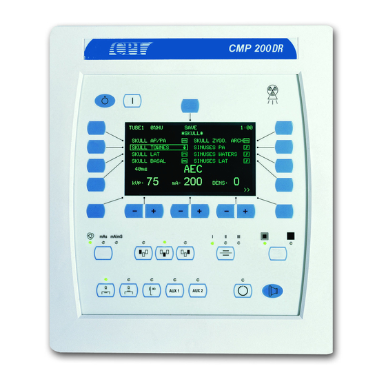
Ensure that the console is mounted at a height and angle to allow for easy viewing of the displays. • If the optional CPI pedestal stand (membrane console) is to be used for the console mounting, follow the mounting instructions supplied with the stand. - Page 37 One set of holes is spaced at 100 mm, and the other set is spaced at 75 mm. CPI recommends the use of the 100 mm spaced VESA holes. Line up the back plate with the touchscreen (observe orientation). Attach the base using the screws provided. See figure 2-1.
-
Page 38: Anchoring The Generator To The Floor
These must be supplied by the installer. EXCESS LENGTHS OF CABLING MUST NEVER BE BUNDLED UP AND STORED INSIDE THE GENERATOR. Use and disclosure is subject to the restrictions on the title page of this CPI document. ® CMP 200... -
Page 39: Control Console
X-ray tube ground connection. Note that this ground wire is required for EMC compliance only. It has no safety impact. Use and disclosure is subject to the restrictions on the title page of this CPI document. ®... - Page 40 Verify that the console cable has been connected correctly prior to powering up the generator. Use and disclosure is subject to the restrictions on the title page of this CPI document. ®...
- Page 41 J19 on the generator control board. INCORRECT CONNECTIONS OR USE OF UNAPPROVED EQUIPMENT MAY RESULT IN INJURY OR EQUIPMENT DAMAGE. Use and disclosure is subject to the restrictions on the title page of this CPI document. ® Page 2-8 CMP 200...
- Page 42 COLLAR INTERFACE SWITCH FILE: CMP RAD_CONS2.CDR Figure 2-4: Rear of control console Use and disclosure is subject to the restrictions on the title page of this CPI document. ® CMP 200 X-Ray Generator Service Manual Ch # 901476-02 Rev. C...
-
Page 43: Hand Switch (Optional)
“D” connector. This connects to J3 on the membrane console or to HS on the touchscreen console. A male 9 pin subminiature “D” connector will need to be provided by the installer if the CPI supplied hand switch is not used. - Page 44 AND THE GENERATOR END OF THE CABLE. CONNECT THE GENERATOR END OF THE SHIELD TO THE GROUND TERMINAL ON THE STATOR TERMINAL BLOCK (FIGURE 2-6). Use and disclosure is subject to the restrictions on the title page of this CPI document. ®...
-
Page 45: Thermal Switch
Ferrules should be used on the ends of the AC mains wires. These must be supplied by the installer. • For China only, the power cable must be CCC approved. Use and disclosure is subject to the restrictions on the title page of this CPI document. ® Page 2-12 CMP 200... - Page 46 ERROR MESSAGES. Do not switch on mains power until requested to do so in a later step. Figure 2-7: Generator mains connection Use and disclosure is subject to the restrictions on the title page of this CPI document. ® CMP 200...
-
Page 47: High Tension Cables
X-ray tube ground connection. Failure to make this ground connection may result in intermittent operation and/or exposure errors. Use and disclosure is subject to the restrictions on the title page of this CPI document. ® Page 2-14... -
Page 48: Room Equipment
HIGH VOLTAGE IS PRESENT ON THE H.V. AUXILIARY BOARD AT ALL TIMES THAT THE GENERATOR IS SWITCHED ON. TAKE APPROPRIATE PRECAUTIONS WHEN SERVICING THIS BOARD Use and disclosure is subject to the restrictions on the title page of this CPI document. ® CMP 200... -
Page 49: Setting 120 / 240 Vac Boost Voltage
Proceed to the next step if the jumper setting is correct. Confirm the proper boost voltage and proper anode rotation as described above. Use and disclosure is subject to the restrictions on the title page of this CPI document. ®... -
Page 50: Low Speed Starter Tube Select Table
Toshiba Rotanode E7254X 240 VAC 739442-00 XH-157 E7254FX 739445-00 E7255X Use and disclosure is subject to the restrictions on the title page of this CPI document. ® CMP 200 X-Ray Generator Service Manual Ch # 901476-02 Rev. C Page 2-17... - Page 51 “STD” or A272 “R” stator A282 A286 A292 Use and disclosure is subject to the restrictions on the title page of this CPI document. ® Page 2-18 CMP 200 X-Ray Generator Service Manual Ch # 901476-02 Rev. C...
-
Page 52: Programming The Dual-Speed Starter
If the desired tube type is not listed, please contact CPI product support for assistance. Use and disclosure is subject to the restrictions on the title page of this CPI document. ®... - Page 53 SWITCH ONLY. DEPENDING ON MANUFACTURER, YOUR DIP SWITCH STYLE MAY VARY. PLEASE NOTE THE ON / OFF POSITIONS CAREFULLY FOR YOUR UNIT. Use and disclosure is subject to the restrictions on the title page of this CPI document. ® Page 2-20...
- Page 54 IN TABLE 2-2 STEP 5 EXAMPLE ONLY CMP_DSS.CDR Figure 2-9: DIP switches on dual-speed starter Use and disclosure is subject to the restrictions on the title page of this CPI document. ® CMP 200 X-Ray Generator Service Manual Ch # 901476-02 Rev.
- Page 55 Installation CPI Canada Inc. (This page intentionally left blank) Use and disclosure is subject to the restrictions on the title page of this CPI document. ® Page 2-22 CMP 200 X-Ray Generator Service Manual Ch # 901476-02 Rev. C...
-
Page 56: Dual Speed Starter Tube Select Table
PX1482 (-13) 901298-13 (see note at end PX1483 of this table) Use and disclosure is subject to the restrictions on the title page of this CPI document. ® CMP 200 X-Ray Generator Service Manual Ch # 901476-02 Rev. C Page 2-23... - Page 57 50 Hz 50 Hz (-12) 901297-13 31 uF 901298-12 (-13) 901298-13 Use and disclosure is subject to the restrictions on the title page of this CPI document. ® CMP 200 X-Ray Generator Service Manual Ch # 901476-02 Rev. C Page 2-24...
- Page 58 901297-13 RTM 92H 901298-13 C352 C52 Super 20/40 Ω stator Use and disclosure is subject to the restrictions on the title page of this CPI document. ® CMP 200 X-Ray Generator Service Manual Ch # 901476-02 Rev. C Page 2-25...
- Page 59 RO 17/50 (-13) (0.6/1.3) 901298-13 RO 20/50 (0.6/1.2) RO 30/50 (1.2/1.8) Use and disclosure is subject to the restrictions on the title page of this CPI document. ® CMP 200 X-Ray Generator Service Manual Ch # 901476-02 Rev. C Page 2-26...
- Page 60 901297-12 XH-106V-2 E7813X (-12) 901297-13 31 uF 901298-12 (-13) 901298-13 Use and disclosure is subject to the restrictions on the title page of this CPI document. ® CMP 200 X-Ray Generator Service Manual Ch # 901476-02 Rev. C Page 2-27...
- Page 61 60 uF 901297-02 B100 A132 901298-02 “Q” stator A142 (6/11 Ω) Use and disclosure is subject to the restrictions on the title page of this CPI document. ® CMP 200 X-Ray Generator Service Manual Ch # 901476-02 Rev. C Page 2-28...
- Page 62 Std “R” stator RAD 74 31 uF 901298-12 (-13) 901298-13 Use and disclosure is subject to the restrictions on the title page of this CPI document. ® CMP 200 X-Ray Generator Service Manual Ch # 901476-02 Rev. C Page 2-29...
- Page 63 1.9 sec boost times are per newer Dunlee data sheets (May 2002). The installer must verify tube compatibility per the appropriate Dunlee tube data sheet. Use and disclosure is subject to the restrictions on the title page of this CPI document. ®...
-
Page 64: Dip Switch Settings
Verify that the mains voltage and current capacity is correct for the generator installation per Generator Power Requirements in chapter 1. Locate the auxiliary transformer inside the generator cabinet. Refer to chapter 1. Use and disclosure is subject to the restrictions on the title page of this CPI document. ® CMP 200... - Page 65 400V or the 480V tap on the transformer primary. This is set to the 400 or 480V tap to match the line voltage specified at the time of the order. Refer to figure 2-11. Use and disclosure is subject to the restrictions on the title page of this CPI document. ®...
-
Page 66: Initial Voltage Measurements
400 V, the dual speed starter EPROM will need to be changed as described in the section EPROM type / dual speed starter. Confirm that this has been done. ___ Check Use and disclosure is subject to the restrictions on the title page of this CPI document. ® CMP 200... -
Page 67: Tube Ma Auto Calibration
THE INSTALLER SHOULD ENSURE THAT ALL CABLE CONNECTIONS TO THE GENERATOR ARE SECURE, AND ALL CABLES EXTERNAL TO THE GENERATOR ARE ADEQUATELY PROTECTED AGAINST ACCIDENTAL DISCONNECTION. Use and disclosure is subject to the restrictions on the title page of this CPI document. ® Page 2-34... - Page 68 Title Not Used Not Used Interfacing and Programming AEC (Automatic Exposure Control) calibration Use and disclosure is subject to the restrictions on the title page of this CPI document. ® CMP 200 X-Ray Generator Service Manual Ch # 901476-03 Rev. A...
- Page 69 Interfacing, Programming, & Calibration CPI Canada Inc. (This page intentionally left blank.) Use and disclosure is subject to the restrictions on the title page of this CPI document. ® Page 3-2 CMP 200 X-Ray Generator Service Manual Ch # 901476-03...
- Page 70 DAP Calibration Procedure ........................3C-76 3C.11.4 DAP Calculation Worksheet ......................... 3C-79 3C.12.0 DATA LINK............................... 3C-82 Use and disclosure is subject to the restrictions on the title page of this CPI document. ® CMP 200 X-Ray Generator Service Manual Ch # 901476-04 Rev.
- Page 71 Configuration Backup / Restore ......................3C-107 3C.13.10 Touchscreen Console Firmware Upgrade / Restore................3C-110 3C.13.11 Generator Configuration Backup and Restore................... 3C-122 Use and disclosure is subject to the restrictions on the title page of this CPI document. ® Page 3C-2...
-
Page 72: 1.0 Introduction
PROGRAMMED. BUCKY 1 WILL NORMALLY BE PROGRAMMED TO CORRESPOND TO THE TABLE BUCKY, AND BUCKY 2 WILL NORMALLY BE PROGRAMMED FOR THE WALL BUCKY OR FOR TOMO. Use and disclosure is subject to the restrictions on the title page of this CPI document. ® CMP 200... -
Page 73: 2.2 Outputs
J11-1 (-) 24 VDC @ 45 watts output for customer use (unswitched). J11-2 (+) Table 3C-2: Generator outputs Use and disclosure is subject to the restrictions on the title page of this CPI document. ® Page 3C-4 CMP 200 X-Ray Generator Service Manual Ch # 901476-04 Rev. - Page 74 RESISTOR, PART OF THE R-C SNUBBER, WILL ELIMINATE THIS PROBLEM. Removing R2 open-circuits the snubber across the K1 contacts, removing R15 defeats the snubber across the contacts of K3. Use and disclosure is subject to the restrictions on the title page of this CPI document. ® CMP 200...
-
Page 75: 2.3 Inputs & Outputs (Simplified Schematic)
OR 220 VAC. REFER TO CHAPTER 8 FOR DETAILS. FILE: CMP200_012B.CDR Figure 3C-1: J2, J4, and J11 inputs and outputs (H.V. auxiliary board) Use and disclosure is subject to the restrictions on the title page of this CPI document. ® Page 3C-6... -
Page 76: 2.4 Aec Interconnect
To enter into the programming mode if using the membrane console, follow the steps below. MENU BACK FORWARD IND100R_006A.CDR Figure 3C-2: Programming / calibration mode reference Use and disclosure is subject to the restrictions on the title page of this CPI document. ® CMP 200 X-Ray Generator Service Manual Ch # 901476-04 Rev. C... - Page 77 Interfacing and Programming CPI Canada Inc. (This page intentionally left blank) Use and disclosure is subject to the restrictions on the title page of this CPI document. ® Page 3C-8 CMP 200 X-Ray Generator Service Manual Ch # 901476-04 Rev. C...
-
Page 78: 4.0 Generator Setup Menu
* GENERATOR SETUP * UTILITY APR EDITOR: DISABLED GEN CONFIGURATION DATA LINK EXIT SETUP Use and disclosure is subject to the restrictions on the title page of this CPI document. ® CMP 200 X-Ray Generator Service Manual Ch # 901476-04 Rev. C... - Page 79 DATA LINK The DATA LINK function on the membrane console is used to communicate with an external computer running GenWare®. Use and disclosure is subject to the restrictions on the title page of this CPI document. ® Page 3C-10 CMP 200...
-
Page 80: 5.0 Utility Menu
* UTILITY * SET TIME & DATE ERROR LOG STATISTICS CONSOLE EXIT Use and disclosure is subject to the restrictions on the title page of this CPI document. ® CMP 200 X-Ray Generator Service Manual Ch # 901476-04 Rev. C... -
Page 81: 5.1 Setting Time And Date
® ® Figure 3C-3a: PC GenWare Figure 3C-3b: Touchscreen GenWare Date and Time utility Use and disclosure is subject to the restrictions on the title page of this CPI document. ® Page 3C-12 CMP 200 X-Ray Generator Service Manual Ch # 901476-04... - Page 82 Select the minutes via the Minute dialog Select the minutes via the Minute dialog the minutes. box. box. Use and disclosure is subject to the restrictions on the title page of this CPI document. ® CMP 200 X-Ray Generator Service Manual Ch # 901476-04 Rev.
-
Page 83: 5.2 Error Log
TIME: 13:09 ERROR CODE: 200 ERROR MESSAGE: ANODE HEAT WARN KVp: EXIT Use and disclosure is subject to the restrictions on the title page of this CPI document. ® Page 3C-14 CMP 200 X-Ray Generator Service Manual Ch # 901476-04... - Page 84 GenWare® toolbar to access the error log GenWare® toolbar. utility Use and disclosure is subject to the restrictions on the title page of this CPI document. ® CMP 200 X-Ray Generator Service Manual Ch # 901476-04 Rev.
-
Page 85: 5.3 Statistics
* STATISTICS * TUBE 1 EXP: RESET TUBE 1 EXP TOTAL EXP: 1100 EXIT Use and disclosure is subject to the restrictions on the title page of this CPI document. ® Page 3C-16 CMP 200 X-Ray Generator Service Manual Ch # 901476-04... - Page 86 ® ® Figure 3C-5a: PC GenWare Figure 3C-5b: Touchscreen GenWare Statistics utility Use and disclosure is subject to the restrictions on the title page of this CPI document. ® CMP 200 X-Ray Generator Service Manual Ch # 901476-04 Rev. C...
- Page 87 The subject exposure counter is reset when the factory defaults are reset. Therefore, the “total exposure” count should be recorded before resetting the factory defaults. Press EXIT to return to the UTILITY menu. Use and disclosure is subject to the restrictions on the title page of this CPI document. ® Page 3C-18 CMP 200...
-
Page 88: 5.4 Console
Since the CONSOLE CONFIG setup affects the console only (setting of specific console operating features to suit operator preferences), no equivalent function is available in GenWare®. Use and disclosure is subject to the restrictions on the title page of this CPI document. ®... - Page 89 NO: The logo is not displayed. LANGUAGE Selects the language for status and error messages (the APR text must be changed via the CPI GenWare® utility software). Use and disclosure is subject to the restrictions on the title page of this CPI document.
- Page 90 Select LOGO ON?. Toggle the button to select YES or NO. Select LANGUAGE. Toggle the button to select the desired language for status and error messages. Use and disclosure is subject to the restrictions on the title page of this CPI document. ®...
-
Page 91: 6.0 Apr Editor
DATA LINK EXIT SETUP No equivalent function exists in GenWare®, as the APR EDITOR affects the console operation only. Use and disclosure is subject to the restrictions on the title page of this CPI document. ® Page 3C-22 CMP 200... - Page 92 Action (membrane console) From the GENERATOR SETUP menu, select APR EDITOR. Toggle the button to select ENABLED or DISABLED. Use and disclosure is subject to the restrictions on the title page of this CPI document. ® CMP 200 X-Ray Generator Service Manual Ch # 901476-04 Rev.
-
Page 93: 7.0 Generator Configuration
A292 0.6/1.2 G1082 0.3/1.0 A272 0.3/0.6 RAD8 1.0/2.0 EXIT >> Use and disclosure is subject to the restrictions on the title page of this CPI document. ® Page 3C-24 CMP 200 X-Ray Generator Service Manual Ch # 901476-04 Rev. C... - Page 94 RO1750 0.6/1.3 DX101HS 0.6/1.3 MX75 1.0/2.0 MX100 0.6/1.25 << >> Use and disclosure is subject to the restrictions on the title page of this CPI document. ® CMP 200 X-Ray Generator Service Manual Ch # 901476-04 Rev. C Page 3C-25...
- Page 95 MAX SF KW LS: 21.3 MAX LF KW LS: 58.9 MAX KV: 125 EXIT >> Use and disclosure is subject to the restrictions on the title page of this CPI document. ® Page 3C-26 CMP 200 X-Ray Generator Service Manual Ch # 901476-04 Rev.
- Page 96 MAX SF MA: ANODE HU WARNING: 80% ANODE HU LIMIT: 90% << RETURN Use and disclosure is subject to the restrictions on the title page of this CPI document. ® CMP 200 X-Ray Generator Service Manual Ch # 901476-04 Rev. C...
- Page 97 ® Figure 3C-6a: PC GenWare Figure 3C-6b: Touchscreen GenWare Tube Selection / Tube Setup window, Tube Library tab Use and disclosure is subject to the restrictions on the title page of this CPI document. ® Page 3C-28 CMP 200 X-Ray Generator Service Manual Ch # 901476-04 Rev.
- Page 98 Figure 3C-7a: PC GenWare Figure 3C-7b: Touchscreen GenWare Tube Selection / Tube Setup window, Tube Settings tab Use and disclosure is subject to the restrictions on the title page of this CPI document. ® CMP 200 X-Ray Generator Service Manual Ch # 901476-04 Rev.
- Page 99 Figure 3C-8b: Touchscreen GenWare Figure 3C-8a: PC GenWare Tube Selection / Tube Setup window, kW Ratings at 100ms tab Use and disclosure is subject to the restrictions on the title page of this CPI document. ® Page 3C-30 CMP 200...
- Page 100 Figure 3C-9a: PC GenWare Figure 3C-9b: Touchscreen GenWare Tube Selection / Tube Setup window, Filament Parameters tab Use and disclosure is subject to the restrictions on the title page of this CPI document. ® CMP 200 X-Ray Generator Service Manual Ch # 901476-04 Rev.
- Page 101 Tube Selection window, Anode Heating tab Note: In touchscreen GenWare®, the Anode Heating function is included in the Tube Settings tab (see figure 3-7b). Use and disclosure is subject to the restrictions on the title page of this CPI document. ®...
- Page 102 The time that the filament is held at the required emission level before an exposure is permitted. FIL PREHEAT Filament Preheat Time (ms) Use and disclosure is subject to the restrictions on the title page of this CPI document. ® CMP 200 X-Ray Generator Service Manual Ch # 901476-04 Rev.
- Page 103 Additional tube types may be downloaded using the console utility in GenWare®. Use and disclosure is subject to the restrictions on the title page of this CPI document. ® Page 3C-34 CMP 200 X-Ray Generator Service Manual Ch # 901476-04 Rev.
- Page 104 Speed dialog box. Select the kW Ratings at 100 ms tab. Select the kW Ratings at 100 ms tab. Use and disclosure is subject to the restrictions on the title page of this CPI document. ® CMP 200 X-Ray Generator Service Manual Ch # 901476-04 Rev.
- Page 105 Max Current (A) dialog current. box, under Large Focus. box, under Large Focus. Use and disclosure is subject to the restrictions on the title page of this CPI document. ® Page 3C-36 CMP 200 X-Ray Generator Service Manual Ch # 901476-04 Rev.
- Page 106 Standby current must be below the emission point. If the maximum filament current is increased, be careful not to exceed the tube manufacturer’s specifications. Use and disclosure is subject to the restrictions on the title page of this CPI document. ®...
- Page 107 MAX MA MIN MA MAX MAS ROTOR BOOST Table 3C-3: X-ray tube and generator parameter worksheet Use and disclosure is subject to the restrictions on the title page of this CPI document. ® Page 3C-38 CMP 200 X-Ray Generator Service Manual Ch # 901476-04 Rev.
-
Page 108: 7.2 Generator Limits
® ® Figure 3C-11a: PC GenWare Figure 3C-11b: Touchscreen GenWare Generator Limits window Use and disclosure is subject to the restrictions on the title page of this CPI document. ® CMP 200 X-Ray Generator Service Manual Ch # 901476-04 Rev. C... - Page 109 PROPOSED CHANGES DO NOT EXCEED THE MANUFACTURERS RECOMMENDED LIMITS. THE ORIGINAL GENERATOR LIMITS SHOULD BE RECORDED IN A COPY OF TABLE 3C-3 BEFORE CONTINUING. Use and disclosure is subject to the restrictions on the title page of this CPI document. ®...
- Page 110 GenWare® GenWare® time. Press EXIT to return to the GEN CONFIGURATION menu. Use and disclosure is subject to the restrictions on the title page of this CPI document. ® CMP 200 X-Ray Generator Service Manual Ch # 901476-04 Rev. C...
-
Page 111: 7.3 Receptor Setup
AEC CHANNEL: 1 AEC BACKUP MAS: 100 AEC BACKUP MS: 1000 << >> Use and disclosure is subject to the restrictions on the title page of this CPI document. ® Page 3C-42 CMP 200 X-Ray Generator Service Manual Ch # 901476-04... - Page 112 FOCUS: SMALL CENTER FIELD: YES FILM SCREEN: 1 RIGHT FIELD: YES << >> Use and disclosure is subject to the restrictions on the title page of this CPI document. ® CMP 200 X-Ray Generator Service Manual Ch # 901476-04 Rev. C...
- Page 113 ® Figure 3C-12b: Touchscreen GenWare Figure 3C-12a: PC GenWare Receptor Setup window, Receptor Properties tab Use and disclosure is subject to the restrictions on the title page of this CPI document. ® Page 3C-44 CMP 200 X-Ray Generator Service Manual Ch # 901476-04 Rev.
- Page 114 ® Figure 3C-13a: PC GenWare Figure 3C-13b: Touchscreen GenWare Receptor Setup window, AEC tab Use and disclosure is subject to the restrictions on the title page of this CPI document. ® CMP 200 X-Ray Generator Service Manual Ch # 901476-04 Rev.
- Page 115 Enables the currently selected receptor. GenWare®: Enables / disables the currently selected receptor. Receptor Enable Use and disclosure is subject to the restrictions on the title page of this CPI document. ® Page 3C-46 CMP 200 X-Ray Generator Service Manual Ch # 901476-04 Rev.
- Page 116 (and vice-versa) switching will occur at the MAX SF MA set point. MAN: The operator must manually select small or large focus. Use and disclosure is subject to the restrictions on the title page of this CPI document. ® CMP 200 X-Ray Generator Service Manual Ch # 901476-04 Rev.
- Page 117 Sets the time that the rotor will continue to spin after a rad exposure has terminated. RAD HANG Rad Hangover (s): Use and disclosure is subject to the restrictions on the title page of this CPI document. ® Page 3C-48...
- Page 118 = field selected. Voltage (kV) Selects the default kV. Current (mA) Selects the default mA. Use and disclosure is subject to the restrictions on the title page of this CPI document. ® CMP 200 X-Ray Generator Service Manual Ch # 901476-04 Rev.
- Page 119 FOCUS FILM SCREEN LEFT FIELD CENTER FIELD RIGHT FIELD DENSITY Use and disclosure is subject to the restrictions on the title page of this CPI document. ® Page 3C-50 CMP 200 X-Ray Generator Service Manual Ch # 901476-04 Rev. C...
- Page 120 – buttons to select the desired interface Interface Options dialog box. the Interface Options dialog box. option. Use and disclosure is subject to the restrictions on the title page of this CPI document. ® CMP 200 X-Ray Generator Service Manual Ch # 901476-04 Rev.
- Page 121 Under Film Screen, select I, II, or III. Under Film Screen, select I, II, or III. to select 1, 2, or 3. Use and disclosure is subject to the restrictions on the title page of this CPI document. ® Page 3C-52...
-
Page 122: 7.4 I/O Configuration
_ _ _ _ STANDBY STATE DOOR ITLK: _ _ _ _ EXIT >> Use and disclosure is subject to the restrictions on the title page of this CPI document. ® CMP 200 X-Ray Generator Service Manual Ch # 901476-04 Rev. C... - Page 123 _ _ _ _ ROOM LIGHT: _ _ _ _ ⇑ << >> Use and disclosure is subject to the restrictions on the title page of this CPI document. ® Page 3C-54 CMP 200 X-Ray Generator Service Manual Ch # 901476-04...
- Page 124 ® Figure 3C-15a: PC GenWare Figure 3C-15b: Touchscreen GenWare Receptor Setup window, Inputs tab Use and disclosure is subject to the restrictions on the title page of this CPI document. ® CMP 200 X-Ray Generator Service Manual Ch # 901476-04 Rev.
- Page 125 Programs the interlock #2 input at J2-1 and J2-2 on the H.V. auxiliary board. This is the tomo exposure input for any receptor that is assigned to tomo operation. Use and disclosure is subject to the restrictions on the title page of this CPI document. ®...
- Page 126 GEN RDY • Sets the state of the I/O when the generator starts a radiographic exposure. RAD EXP Use and disclosure is subject to the restrictions on the title page of this CPI document. ® CMP 200 X-Ray Generator Service Manual Ch # 901476-04 Rev.
- Page 127 For outputs, an unchecked state causes the relay associated with that output to be de-energized during the selected state. A checked state (marked with an X) will cause the associated relay to be energized during the selected state. Use and disclosure is subject to the restrictions on the title page of this CPI document. ®...
- Page 128 GEN the current receptor. the current receptor. CONFIGURATION menu. Use and disclosure is subject to the restrictions on the title page of this CPI document. ® CMP 200 X-Ray Generator Service Manual Ch # 901476-04 Rev.
- Page 129 BUCKY 2 RDY OUTPUTS BKY 1 START BKY 2 START ROOM LIGHT Use and disclosure is subject to the restrictions on the title page of this CPI document. ® Page 3C-60 CMP 200 X-Ray Generator Service Manual Ch # 901476-04...
-
Page 130: 7.5 Aec Setup
* AEC SETUP* R FIELD COMP: C FIELD COMP: L FIELD COMP: << Use and disclosure is subject to the restrictions on the title page of this CPI document. ® CMP 200 X-Ray Generator Service Manual Ch # 901476-04 Rev. C... - Page 131 ® ® Figure 3C-18a: PC GenWare Figure 3C-18b: Touchscreen GenWare AEC Setup & Calibration window Use and disclosure is subject to the restrictions on the title page of this CPI document. ® Page 3C-62 CMP 200 X-Ray Generator Service Manual Ch # 901476-04 Rev.
- Page 132 GenWare®: Refer to the graphic under Fields: A black field select rectangle = disabled, a green field select rectangle = enabled. Use and disclosure is subject to the restrictions on the title page of this CPI document. ® CMP 200...
- Page 133 C FIELD COMP C. Field Comp chapter 3D. L FIELD COMP L. Field Comp Use and disclosure is subject to the restrictions on the title page of this CPI document. ® Page 3C-64 CMP 200 X-Ray Generator Service Manual Ch # 901476-04...
- Page 134 3. Press >>. Select the AEC setup tab. Select the AEC setup tab. Use and disclosure is subject to the restrictions on the title page of this CPI document. ® CMP 200 X-Ray Generator Service Manual Ch # 901476-04 Rev.
-
Page 135: 7.6 Aec Calibration
ALWAYS VERIFY THE MANUFACTURER OF THE TUBE INSERT. IF THE X-RAY TUBE HAS BEEN REBUILT, THE TUBE INSERT AND TUBE HOUSING MAY BE FROM DIFFERENT MANUFACTURERS. Use and disclosure is subject to the restrictions on the title page of this CPI document. ®... - Page 136 WILL THEN LIMIT THE TUBES OPERATION TO THE RANGE IN WHICH IT WAS CALIBRATED, THUS ALLOWING FOR PARTIAL OPERATION OF THE GENERATOR. Use and disclosure is subject to the restrictions on the title page of this CPI document. ® CMP 200...
-
Page 137: 8.0 Dap Printer Setup
9-pin male “D” connector that is designed to plug directly into the generator control board. If this cable is not available from the DAP device manufacturer, consult CPI product support for the required cable to connect the DAP chamber to the generator. Refer to the table below for the CPI cable assembly part numbers. -
Page 138: 9.2 Dap Installation
Jumper pins 1-2 Jumper pins 2-3 Proceed with DAP setup and calibration as per the remainder of this procedure. Use and disclosure is subject to the restrictions on the title page of this CPI document. ® CMP 200 X-Ray Generator Service Manual Ch # 901476-04 Rev. -
Page 139: 10.0 Dap Setup
MENU 2: DAP RESET / TEST / PRINT EXIT DAP = 0mGycm PRINT RESET TEST Use and disclosure is subject to the restrictions on the title page of this CPI document. ® Page 3C-70 CMP 200 X-Ray Generator Service Manual Ch # 901476-04 Rev. C... - Page 140 ® Figure 3C-19a: PC GenWare Figure 3C-19b: Touchscreen GenWare DAP Setup and display windows Use and disclosure is subject to the restrictions on the title page of this CPI document. ® CMP 200 X-Ray Generator Service Manual Ch # 901476-04 Rev.
- Page 141 Selects the Seiko Instruments DPU-414 printer. SLP200: Selects the Seiko Instruments SLP-200 printer. Use and disclosure is subject to the restrictions on the title page of this CPI document. ® Page 3C-72 CMP 200 X-Ray Generator Service Manual Ch # 901476-04...
-
Page 142: 10.2
A pass / fail message will be presented after the DAP test, and the actual number of test pulses counted will be displayed. Use and disclosure is subject to the restrictions on the title page of this CPI document. ®... - Page 143 Press PRINT to print a DAP label. Press EXIT to return to the DAP SETUP menu. Use and disclosure is subject to the restrictions on the title page of this CPI document. ® Page 3C-74 CMP 200 X-Ray Generator Service Manual Ch # 901476-04 Rev.
-
Page 144: 11.0 Dap Calibration
This is also the reason that care must be taken to ensure that the area measurement is done at the same distance from the X-ray source as the dose measurement. Use and disclosure is subject to the restrictions on the title page of this CPI document. ®... -
Page 145: 11.3 Dap Calibration Procedure
DAP chamber 2 TUBE 2 TYPICAL SETUP FOR DAP CALIBRATION FILE: DAP.CDR Figure 3C-20: DAP setup Use and disclosure is subject to the restrictions on the title page of this CPI document. ® Page 3C-76 CMP 200 X-Ray Generator Service Manual Ch # 901476-04 Rev. - Page 146 Calculate the dose-area product by multiplying the area from table 3C-4 X the dose in mGy from table 3C-4. Record the resulting value at step 3 in table 3C-4. Use and disclosure is subject to the restrictions on the title page of this CPI document. ®...
- Page 147 ILLUMINATED DEVELOPED FILM COLLIMATOR FIELD Figure 3C-21: Irradiated area vs. available image area Use and disclosure is subject to the restrictions on the title page of this CPI document. ® Page 3C-78 CMP 200 X-Ray Generator Service Manual Ch # 901476-04...
-
Page 148: 11.4 Dap Calculation Worksheet
_____________ % error the end of this section. THIS TABLE IS REPEATED BELOW FOR THE SECOND ITERATION OF THE DAP CALIBRATION. Use and disclosure is subject to the restrictions on the title page of this CPI document. ® CMP 200... - Page 149 Calculate the percentage error: Refer to the example at _____________ % error the end of this section. Table 3C-4: DAP worksheets Use and disclosure is subject to the restrictions on the title page of this CPI document. ® Page 3C-80 CMP 200...
- Page 150 Sample percentage error calculation (step 5): (36.44 - 40) -3.56 X 100 = X 100 = -8.9 % Use and disclosure is subject to the restrictions on the title page of this CPI document. ® CMP 200 X-Ray Generator Service Manual Ch # 901476-04 Rev.
-
Page 151: 12.0 Data Link
“Rear of control console” in chapter 2 for the location of this connector. If the data link connector is not available, i.e. on units without a CPI supplied console, the computer running PC GenWare® must be connected to J3 on the generator control board as described below. A special serial cable with a 9 pin female “D” connector on one end and an RJ45 ethernet style connector on the other end is needed for this step. -
Page 152: 13.0 Touchscreen System Utilities
Main Menu Press to return to the main console menu. Use and disclosure is subject to the restrictions on the title page of this CPI document. ® CMP 200 X-Ray Generator Service Manual Ch # 901476-04 Rev. -
Page 153: 13.1 Accessing The Utilities Menu
If this was done, the password defined above will not allow access to the system utilities menu. Figure 3C-22: Main menu Use and disclosure is subject to the restrictions on the title page of this CPI document. ® Page 3C-84... - Page 154 CPI Canada Inc. Interfacing and Programming 3C.13.1 Accessing the Utilities Menu (Cont) Figure 3C-23: Password window Use and disclosure is subject to the restrictions on the title page of this CPI document. ® CMP 200 X-Ray Generator Service Manual Ch # 901476-04 Rev.
-
Page 155: 13.2 Apr Editor
Refer to the applicable subsections (following) for the procedures to change parameters and technique for existing APR items, and to edit, add, or delete APR, procedural, or menu items. Use and disclosure is subject to the restrictions on the title page of this CPI document. ®... - Page 156 This will highlight the item. Press <Move Up> to move the selected item up in the list, and <Move Down> to move the selected item down in the list. Use and disclosure is subject to the restrictions on the title page of this CPI document. ®...
- Page 157 Touching the ID code window will move the cursor into that window, allowing entry of the ID code. THE I.D. CODE IS NOT AVAILABLE ON ALL SOFTWARE CONFIGURATIONS OF THE TOUCHSCREEN. Use and disclosure is subject to the restrictions on the title page of this CPI document. ®...
- Page 158 Press OK to continue. Cancel will cancel this action. Use and disclosure is subject to the restrictions on the title page of this CPI document. ® CMP 200...
- Page 159 To add a procedural item, follow steps 1 to 3 in “To add an APR item”, except select APR Procedure in step 2. Use and disclosure is subject to the restrictions on the title page of this CPI document. ®...
- Page 160 You may now edit the name and change the parameters and technique for that APR item, and add additional APR items for that menu item as per previous steps. Use and disclosure is subject to the restrictions on the title page of this CPI document. ®...
-
Page 161: 13.3 Apr Backup / Restore
APR files to and from a USB flash drive. The entire APR (parameters and techniques, APR text, menu structures, etc) is backed up. Figure 3C-26: APR back-up and restore window Use and disclosure is subject to the restrictions on the title page of this CPI document. ® Page 3C-92... - Page 162 Action Press Factory Defaults. After a brief delay, a pop-up window will display indicating that restore was successful. Press OK. Use and disclosure is subject to the restrictions on the title page of this CPI document. ® CMP 200 X-Ray Generator Service Manual Ch # 901476-04 Rev.
- Page 163 . After a brief auto-detection sequence where the touchscreen looks for the USB flash drive, the USB File Transfer Utility window (figure 3C-27) will open. Figure 3C-27: USB File Transfer Utility window Use and disclosure is subject to the restrictions on the title page of this CPI document. ® Page 3C-94...
-
Page 164: 13.4 Date / Time Setup
Press the up or down arrows to the right of Hour to select the desired hour. The selected hour will display to the left of the up / down selection buttons. This must be selected in 24 hour format, i.e. 2 PM would be entered as hour 14. Use and disclosure is subject to the restrictions on the title page of this CPI document. ®... - Page 165 Cancel returns to the system utilities menu without applying changes to the time or date. Figure 3C-28: Date and time setup window Use and disclosure is subject to the restrictions on the title page of this CPI document. ® Page 3C-96...
-
Page 166: 13.5 Receptor Symbols
To copy receptor symbol files to and from a USB flash drive press to access the USB File Transfer Utility Use and disclosure is subject to the restrictions on the title page of this CPI document. ® CMP 200 X-Ray Generator Service Manual Ch # 901476-04 Rev. - Page 167 . Once the file has been successfully copied it will appear in the Touch Screen window. When finished press Close to exit. Figure 3C-29: Receptor symbols window Use and disclosure is subject to the restrictions on the title page of this CPI document. ® Page 3C-98...
-
Page 168: 13.6 Touchscreen Setup
The touchscreen setup window will be displayed (figure 3C-30). This has three tabs, SETTINGS, FEATURES and PASSWORDS that will be discussed in sequence. Use and disclosure is subject to the restrictions on the title page of this CPI document. ®... - Page 169 The Customer Code is a unique code assigned to each customer and selects the color scheme and graphic style (skin) to be displayed on the touchscreen console. Use and disclosure is subject to the restrictions on the title page of this CPI document. ®...
- Page 170 Set the General Volume by dragging the slider to the left (lower) or right (louder). This sets the loudness of the button clicks. Use and disclosure is subject to the restrictions on the title page of this CPI document. ®...
- Page 171 From the touchscreen setup window, select FEATURES. Available digital interfaces will be shown on this screen. Figure 3C-31: Touchscreen setup window, Features tab Use and disclosure is subject to the restrictions on the title page of this CPI document. ®...
- Page 172 Press Accept to accept the new password. Repeat the previous step to enter the new password on the second operator password line. Use and disclosure is subject to the restrictions on the title page of this CPI document. ® CMP 200...
- Page 173 Press Accept to accept the new password. Repeat the previous step to enter the new password on the second service password line. Use and disclosure is subject to the restrictions on the title page of this CPI document. ® Page 3C-104...
-
Page 174: 13.7 Touchscreen Calibration
DISPLAYED PRESS ALT-C TO INITIATE THE CALIBRATION PROCEDURE. FOLLOW THE STEPS ON THE PREVIOUS PAGE TO COMPLETE THE TOUCHSCREEN CALIBRATION. CPI RECOMMENDS NO OTHER BUTTONS BE PRESSED ON THE USB KEYBOARD AS THIS MAY INADVERTENTLY CAUSE CORRUPTION OF THE TOUCHSCREEN SOFTWARE. -
Page 175: 13.8 Data Link
3C.13.8 Data Link This is used with the CPI PC GenWare® utility software. This allows for data communication with a computer in order to download additional tube types, transfer APR data, edit APR text, perform setup and calibration functions, upgrade generator software and for other minor functions. -
Page 176: 13.9 Configuration Backup / Restore
/ auto-position symbols, and to upload and download receptor / auto-position symbols to and from a USB flash drive. Figure 3C-33: Configuration back-up and restore window Use and disclosure is subject to the restrictions on the title page of this CPI document. ® CMP 200... - Page 177 Press Delete. A pop-up window will display asking if you are sure you want to delete this file. Press YES to delete the file; NO cancels the deletion. Use and disclosure is subject to the restrictions on the title page of this CPI document. ®...
- Page 178 . After a brief auto-detection sequence where the touchscreen looks for the USB flash drive, the USB File Transfer Utility window will open. Figure 3C-34: USB File Transfer Utility window Use and disclosure is subject to the restrictions on the title page of this CPI document. ® CMP 200...
-
Page 179: 13.10 Touchscreen Console Firmware Upgrade / Restore
Select Upgrade via a USB Memory Stick. A pop-up window will display with a list of available firmware files (see figure 3C-35). Note: The firmware file will always have the .cpm extension. Select the desired upgrade file and press Open. Use and disclosure is subject to the restrictions on the title page of this CPI document. ®... - Page 180 Note: Any Upgrade Packet that is of an earlier version than the one already installed will appear in red. Use and disclosure is subject to the restrictions on the title page of this CPI document. ®...
- Page 181 Once the installation process is finished a pop-up window will display stating: It is very important that you do not disturb this process (see figure 3C-37). The flash memory is being erased and reloaded with the upgraded firmware. Use and disclosure is subject to the restrictions on the title page of this CPI document. ®...
- Page 182 Step Action Once the update is complete, a pop-up window will display indicating Upgrade Complete. Press OK. Use and disclosure is subject to the restrictions on the title page of this CPI document. ® CMP 200 X-Ray Generator Service Manual Ch # 901476-04 Rev.
- Page 183 (see figure 3C-38). Press the upgrade switch (SW1) on the back of the touchscreen and then select OK. The touchscreen will reboot and you will be taken back to the main menu. Use and disclosure is subject to the restrictions on the title page of this CPI document. ®...
- Page 184 A System Information screen will display containing details of the firmware that is loaded on your touchscreen console. Press NEXT. This will take you to the Upgrade Media Selection window. Launch CPI Touch Screen Updater (see figure 3C-39) from your computer and click the START button. Figure 3C-39: CPI Touch Screen Updater Use and disclosure is subject to the restrictions on the title page of this CPI document.
- Page 185 Another pop-up window will open entitled Select Communication Media (figure 3C-41). Select USB from the Media Types section. Do not alter the Media Config section in any way. It is set automatically. Use and disclosure is subject to the restrictions on the title page of this CPI document. ®...
- Page 186 From the Upgrade Media Selection window select Upgrade via a USB to Computer Connection. The CPI Touch Screen Updater will read the available firmware packets (see figure 3C-42). Use and disclosure is subject to the restrictions on the title page of this CPI document. ®...
- Page 187 CPI Canada Inc. 3C.13.10 Touchscreen Console Firmware Upgrade / Restore (Cont) Figure 3C-42: CPI Touch Screen Updater (after Upgrade Media is selected) Use and disclosure is subject to the restrictions on the title page of this CPI document. ® Page 3C-118...
- Page 188 NOTE: ANY UPGRADE PACKET THAT IS OF AN EARLIER VERSION OF THE ONE ALREADY INSTALLED WILL APPEAR IN RED. Use and disclosure is subject to the restrictions on the title page of this CPI document. ® CMP 200...
- Page 189 (see figure 3C-44). The flash memory is being erased and reloaded with the upgraded firmware. Figure 3C-44: Erasing Flash memory pop-up window Use and disclosure is subject to the restrictions on the title page of this CPI document. ®...
- Page 190 (figure 3C-45). Press the upgrade switch (SW1) on the back of the touchscreen console and then select OK. The touchscreen will reboot and you will be taken back to the Main Menu. Use and disclosure is subject to the restrictions on the title page of this CPI document. ®...
-
Page 191: 13.11 Generator Configuration Backup And Restore
Touchscreen GenWare® must be launched before proceeding. This is done from the GenWare® button on the touchscreen System Utilities menu. Press the button to launch the Backup and Restore utility. Use and disclosure is subject to the restrictions on the title page of this CPI document. ® Page 3C-122 CMP 200... - Page 192 The copied file will appear in the Touch Screen window. Use and disclosure is subject to the restrictions on the title page of this CPI document. ® CMP 200...
- Page 193 Press the button to delete the file from the touchscreen. The file will be removed from the Touch Screen window. Use and disclosure is subject to the restrictions on the title page of this CPI document. ® Page 3C-124 CMP 200...
- Page 194 3D.9.1 AEC Setup Worksheet ..........................3D-37 3D.9.2 AEC Precalibration Checks........................3D-39 3D.9.3 AEC Chamber Installation........................3D-39 Use and disclosure is subject to the restrictions on the title page of this CPI document. ® CMP 200 Service Manual Ch # 901476-05 Rev. A Page 3D-1...
- Page 195 Connect the AEC device to the AEC board as per 3D.2.1 to 3D.2.4. Supplementary information is in the AEC compatibility matrixes. Use and disclosure is subject to the restrictions on the title page of this CPI document. ® Page 3D-2 Rev.
-
Page 196: Aec Board (Solid State Chambers)
• R3 is used for channel 3 gain adjustment. • R4 is used for channel 4 gain adjustment. Use and disclosure is subject to the restrictions on the title page of this CPI document. ® CMP 200 Service Manual Ch # 901476-05 Rev. - Page 197 Jumper JW5, JW6 pins 1-2 (N) Jumper JW5, JW6 pins 2-3 (R) Jumper JW7, JW8 pins 1-2 (N) Jumper JW7, JW8 pins 2-3 (R) Use and disclosure is subject to the restrictions on the title page of this CPI document. ® Page 3D-4 Rev. A...
-
Page 198: 2.2
R13 is used for channel 3 short exposure time compensation. • R14 is used for channel 4 short exposure time compensation. Use and disclosure is subject to the restrictions on the title page of this CPI document. ® CMP 200... - Page 199 Middle field select Left field select Chamber output Table 3D-4: Pin outs for 12 pin in-line connector (J1 to J4) Use and disclosure is subject to the restrictions on the title page of this CPI document. ® Page 3D-6 Rev. A...
-
Page 200: 2.3
• R13 is used for channel 3 gain adjustment. • R14 is used for channel 4 gain adjustment. Use and disclosure is subject to the restrictions on the title page of this CPI document. ® CMP 200 Service Manual Ch # 901476-05 Rev. - Page 201 Jumper JW3, JW4 pins 1-2 (N) Jumper JW3, JW4 pins 2-3 (R) Jumper JW1, JW2 pins 1-2 (N) Jumper JW1, JW2 pins 2-3 (R) Use and disclosure is subject to the restrictions on the title page of this CPI document. ® Page 3D-8 Rev. A...
-
Page 202: 2.4
• R11 is used for channel 1 gain adjustment. • R12 is used for channel 2 gain adjustment. Use and disclosure is subject to the restrictions on the title page of this CPI document. ® CMP 200 Service Manual Ch # 901476-05 Rev. - Page 203 SETUP MENU 2 MUST ALL BE SET TO . THE AEC FIELD BALANCE MUST BE DONE AS PER A.I.D.’s RECOMMENDED PROCEDURE. Use and disclosure is subject to the restrictions on the title page of this CPI document. ® Page 3D-10 Rev.
-
Page 204: Precalibration Notes
A supply of film in each film speed that will be calibrated. • A cassette with intensifying screen in each speed that will be calibrated. Use and disclosure is subject to the restrictions on the title page of this CPI document. ® CMP 200... -
Page 205: 3.0
* AEC CALIBRATION * FILM SCREEN 1 DENSITY SETUP FILM SCREEN 2 FILM SCREEN 3 EXIT Use and disclosure is subject to the restrictions on the title page of this CPI document. ® Page 3D-12 Rev. A CMP 200 Service Manual... - Page 206 << >> * AEC CAL, F/S1 * 110KV: 34.0 130KV: 28.0 << Use and disclosure is subject to the restrictions on the title page of this CPI document. ® CMP 200 Service Manual Ch # 901476-05 Rev. A Page 3D-13...
- Page 207 Set up the X-ray tube stand as shown in figure 3D-5. Align the tube stand and table Bucky such that the central ray is centered relative to the image receptor. Use and disclosure is subject to the restrictions on the title page of this CPI document. ®...
- Page 208 Film Screen 1 (the slowest film select Film Screen 1 (the slowest film screen combination). screen combination). screen combination). Use and disclosure is subject to the restrictions on the title page of this CPI document. ® CMP 200 Service Manual Ch # 901476-05 Rev.
- Page 209 The mAs values noted in the above table represent the approximate desired mAs at an SID of 40 in. (100 cm), using a grid with a 12:1 ratio. All measurements were done with HVL = 3 mm Al @ 75 kV. Use and disclosure is subject to the restrictions on the title page of this CPI document. ®...
- Page 210 3C such that the left field matches the center field. Do not adjust the center field (C) compensation value. Repeat steps 23 and 24 for the right field. Use and disclosure is subject to the restrictions on the title page of this CPI document. ® CMP 200...
- Page 211 DO NOT READJUST THE AEC BOARD DO NOT READJUST THE AEC BOARD GAIN POT. GAIN POT. GAIN POT. Use and disclosure is subject to the restrictions on the title page of this CPI document. ® CMP 200 Service Manual Ch # 901476-05 Rev.
- Page 212 20 cm H 2.5 mAs 250 mA 250 mAs (MAX) Table 3D-8: Target breakpoint calibration factors Use and disclosure is subject to the restrictions on the title page of this CPI document. ® CMP 200 Service Manual Ch # 901476-05 Rev.
- Page 213 Table 3D-8: Target breakpoint calibration factors (Cont) NOTE: For SID’s other than 40 in. (100 cm) multiply the mAs by the factor [new SID / 40 in. (100 cm)] Use and disclosure is subject to the restrictions on the title page of this CPI document. ®...
- Page 214 #8 BK. POINT = 95 kV mAs = CAL. NO. = O.D. = Table 3D-9: Breakpoint calibration worksheet Use and disclosure is subject to the restrictions on the title page of this CPI document. ® CMP 200 Service Manual Ch # 901476-05 Rev.
- Page 215 #8 BK. POINT = 95 kV mAs = CAL. NO. = O.D. = Table 3D-9: Breakpoint calibration worksheet (Cont) Use and disclosure is subject to the restrictions on the title page of this CPI document. ® CMP 200 Service Manual Ch # 901476-05 Rev.
- Page 216 Action (membrane console) Action (PC GenWare®) Action (Touchscreen GenWare®) Select << to return to the AEC CALIBRATION menu. Use and disclosure is subject to the restrictions on the title page of this CPI document. ® CMP 200 Service Manual Ch # 901476-05 Rev.
-
Page 217: Short Aec Time Compensation
AEC time compensation pot and the AEC gain pot by repeating steps 3 to 8. Repeat steps 1 to 10 for each image receptor (AEC channel) to be short AEC time compensated. Use and disclosure is subject to the restrictions on the title page of this CPI document. ®... - Page 218 * DENS. SETUP * -4: 50% -3: 37% -2: 25% -1: 12% << >> Use and disclosure is subject to the restrictions on the title page of this CPI document. ® CMP 200 Service Manual Ch # 901476-05 Rev. A Page 3D-25...
-
Page 219: 5.0 Aec Density Calibration
* DENS. SETUP * +5: 62% +6: --- +7: --- +8: --- << >> Use and disclosure is subject to the restrictions on the title page of this CPI document. ® CMP 200 Service Manual Ch # 901476-05 Rev. A Page 3D-26... - Page 220 12.5% per density plus step (8 steps x 12.5% per step = 100% mAs increase at +8 density). Use and disclosure is subject to the restrictions on the title page of this CPI document. ®...
- Page 221 DENSITY = DOUBLE THE DOSE) DENSITY = DOUBLE THE DOSE) 0 DENSITY: SHOWN FOR REFERENCE ONLY. Table 3D-10: Example density values Use and disclosure is subject to the restrictions on the title page of this CPI document. ® CMP 200 Service Manual Ch # 901476-05 Rev.
- Page 222 DENS. SETUP menus using the >> and << buttons in order to access the required density steps. Use and disclosure is subject to the restrictions on the title page of this CPI document. ® CMP 200 Service Manual Ch # 901476-05 Rev.
- Page 223 Repeat the previous step for each remaining density plus step. Press << or RETURN as required to return to the AEC CALIBRATION menu. Use and disclosure is subject to the restrictions on the title page of this CPI document. ® CMP 200...
-
Page 224: 6.0 Aec Calibration (Wall Bucky)
If the wall Bucky will be used for conventional as well as chest radiography, then two grids should ideally be used. See the note on the next page. A reasonable compromise if a single grid must be used is a 10:1 ratio, 60 in. (150 cm) grid. Use and disclosure is subject to the restrictions on the title page of this CPI document. ® CMP 200... - Page 225 A 12:1 ratio 40 in. (100 cm) focused grid will exhibit the following absorption when measured 5 in. (13 cm) from center: At 72 in. (180 cm) absorption = 75% Use and disclosure is subject to the restrictions on the title page of this CPI document. ® CMP 200...
- Page 226 Measure the O.D. The desired value should have been previously recorded in a copy of table 3D-11. Use and disclosure is subject to the restrictions on the title page of this CPI document. ® CMP 200...
- Page 227 THE MEMORY FUNCTION THAT WAS TEMPORARILY CHANGED TO OFF EARLIER IN THIS CHAPTER MAY NOW BE RESET TO THE DESIRED VALUE. Use and disclosure is subject to the restrictions on the title page of this CPI document. ® CMP 200...
- Page 228 High kV: 85, 95, 110, 130 kV. Refer to figure 3D-9. Figure 3D-9: kV vs. relative density Use and disclosure is subject to the restrictions on the title page of this CPI document. ® CMP 200 Service Manual Ch # 901476-05 Rev.
- Page 229 MEDIUM SLOW AEC CALIBRATION NUMBERS (D/A OUTPUT) FILE: ML_AECDA.CDR Figure 3D-10: Film/screen speed vs. D/A output Use and disclosure is subject to the restrictions on the title page of this CPI document. ® Page 3D-36 Rev. A CMP 200 Service Manual...
- Page 230 ALL RECEPTORS MUST HAVE THE SAME NUMBER OF DENSITY STEPS AND THE SAME DENSITY DOSE CHANGE PER STEP (DENSITY SETTINGS ARE COMMON TO ALL FILM SCREENS AND RECEPTORS). Use and disclosure is subject to the restrictions on the title page of this CPI document. ®...
-
Page 231: Aec Calibration (Misc)
Wall Are all cassettes similar? Additional notes: Additional notes: Table 3D-12: Sample AEC setup worksheet Use and disclosure is subject to the restrictions on the title page of this CPI document. ® Page 3D-38 Rev. A CMP 200 Service Manual... -
Page 232: Aec Precalibration Checks
Figure 3D-11 shows an installed AEC chamber. Note particularly the use of a suitable insulating material to isolate the body of the chamber from the receptor ground. This is required for non-insulated AEC chambers. Use and disclosure is subject to the restrictions on the title page of this CPI document. ®... - Page 233 AEC Calibration CPI Canada Inc. 3D.9.3 AEC Chamber Installation (Cont) Figure 3D-11: AEC chamber installation Use and disclosure is subject to the restrictions on the title page of this CPI document. ® Page 3D-40 Rev. A CMP 200 Service Manual...
- Page 234 ACCEPTANCE TESTS (DR INTERFACE) ....................4-7 4.6.0 ACCEPTANCE TESTS (DAP)........................4-8 4.8.0 ACCEPTANCE TESTS (HVL, LINEARITY AND REPRODUCIBILITY)........... 4-8 Use and disclosure is subject to the restrictions on the title page of this CPI document. ® CMP 200 X-Ray Generator Service Manual Ch # 901476-06 Rev.
-
Page 235: Introduction
Current probe 0 to 20 amps AC. • A set of HVL filters. • Calculator. Use and disclosure is subject to the restrictions on the title page of this CPI document. ® Page 4-2 CMP 200 X-Ray Generator Service Manual Ch # 901476-06 Rev. -
Page 236: Acceptance Tests (Basic Functions)
Press the focus select button. The large and small focal spot LED’s alternately light as the switch is pressed. Use and disclosure is subject to the restrictions on the title page of this CPI document. ® CMP 200 X-Ray Generator Service Manual Ch # 901476-06 Rev. -
Page 237: Console Tests
Should agree with the value in the dual speed starter table in the supplement at the end of chapter 2. Use and disclosure is subject to the restrictions on the title page of this CPI document. ® Page 4-4 CMP 200... -
Page 238: Acceptance Tests (Kv, Time, Ma And Mas)
Connect the output of the kV measuring device to channel 1 of the oscilloscope. Use and disclosure is subject to the restrictions on the title page of this CPI document. ® CMP 200 X-Ray Generator Service Manual Ch # 901476-06 Rev. - Page 239 C: 12 mAs ± 5%. C: 63 ms (12 mAs) D: 20 mAs ± 5%. D: 100 ms (20 mAs) Use and disclosure is subject to the restrictions on the title page of this CPI document. ® Page 4-6 CMP 200...
- Page 240 For CMP 200® DR X-ray generators with a DR imaging system, follow the system manufacturer’s recommendations for system test to verify the DR interface. Use and disclosure is subject to the restrictions on the title page of this CPI document. ®...
-
Page 241: Acceptance Tests (Aec)
The procedure for performing reproducibility, linearity and HVL testing is contained in a separate document, part number 740917 that immediately follows this page. Use and disclosure is subject to the restrictions on the title page of this CPI document. ®... - Page 242 The information contained herein is loaned in confidence solely for the installation, operation, and maintenance of CPI equipment. This document may not be duplicated in whole or in part, or be used for re-engineering, reverse engineering, or otherwise reproducing in any form or creating or attempting to create or permitting, allowing or assisting others to create or manufacture CPI’s product or products derived therefrom, without the express written...
-
Page 243: Introduction
OPERATION AT THAT KVP VALUE, AND THE TUBE SHOULD FIRST BE SEASONED TO ENSURE THAT OPERATION AT HIGH KVP VALUES WILL NOT BE PROBLEMATIC. Use and disclosure is subject to the restrictions on the title page of this CPI document. Page 2 Rev. -
Page 244: Equipment Setup
= mA X time in seconds (example for 160 mA and 125 ms, mAs = 160 X 0.125 = 20 mAs). Use and disclosure is subject to the restrictions on the title page of this CPI document. X-Ray Generator Service Manual Supplement 740917-00 Rev. - Page 245 S = __________ Calculate reproducibility = = _________ (not to exceed 0.045) Table 1: Reproducibility Use and disclosure is subject to the restrictions on the title page of this CPI document. Page 4 Rev. C X-Ray Generator Service Manual Supplement...
- Page 246 S = __________ Calculate reproducibility = = _________ (not to exceed 0.045) Table 3: Reproducibility Use and disclosure is subject to the restrictions on the title page of this CPI document. X-Ray Generator Service Manual Supplement 740917-00 Rev. C Page 5...
- Page 247 S = _0.0230_ Calculate reproducibility = = _0.011_ (not to exceed 0.045) Table 5: Reproducibility Use and disclosure is subject to the restrictions on the title page of this CPI document. Page 6 Rev. C X-Ray Generator Service Manual Supplement...
-
Page 248: Linearity
Table 6: Linearity mAs = __________ EXP No. DOSE (mGy) K = ________ Table 7: Linearity Use and disclosure is subject to the restrictions on the title page of this CPI document. X-Ray Generator Service Manual Supplement 740917-00 Rev. C Page 7... - Page 249 In the numerator of the above equation, use the absolute value of X (disregard the minus sign). Table 9: Linearity Use and disclosure is subject to the restrictions on the title page of this CPI document. Page 8 Rev. C...
-
Page 250: Evaluation
100 kV, 200 mA if this can be set, and 10 mAs. Use table 11 to record the values and figure 2 to plot the results Table 12 and figure 3 show example HVL determination. Use and disclosure is subject to the restrictions on the title page of this CPI document. X-Ray Generator Service Manual Supplement 740917-00 Rev. - Page 251 Table 10: HVL dose values 80 kVp Figure 1: HVL plot 80 kVp For 80 kVp, the HVL must be ≥ 2.9 mm Al. Use and disclosure is subject to the restrictions on the title page of this CPI document. Page 10 Rev. C...
- Page 252 Table 11: HVL dose values 100 kVp Figure 2: HVL plot 100 kVp For 100 kVp, the HVL must be ≥ 3.6 mm Al. Use and disclosure is subject to the restrictions on the title page of this CPI document. X-Ray Generator Service Manual Supplement 740917-00 Rev.
- Page 253 By interpolating the thickness of Al at a relative transmission value of 0.5, it can be seen that the HVL is approximately 3.3. Use and disclosure is subject to the restrictions on the title page of this CPI document. Page 12 Rev.
- Page 254 HV Auxiliary Board ............................5-14 5.4.4 EMC Capacitor Board ..........................5-14 5.4.5 AEC Board ..............................5-15 Use and disclosure is subject to the restrictions on the title page of this CPI document. ® CMP 200 X-Ray Generator Service Manual Ch # 901476-07 Rev.
-
Page 255: Troubleshooting
This chapter contains tables of those messages and suggests actions to be taken by service personnel to correct any malfunctions that may occur. Use and disclosure is subject to the restrictions on the title page of this CPI document. ®... -
Page 256: Status And Error Codes
DAP accumulation The accumulated DAP value exceeds the Reset the DAP. Warning. programmed DAP limit. Use and disclosure is subject to the restrictions on the title page of this CPI document. ® CMP 200 X-Ray Generator Service Manual Ch # 901476-07 Rev. - Page 257 Tube mAs limit Requested mAs not allowed as tube mAs limit None. has been reached. Use and disclosure is subject to the restrictions on the title page of this CPI document. ® CMP 200 X-Ray Generator Service Manual Ch # 901476-07 Rev.
- Page 258 2. Check for poor connections in the cathode cable. 3. Check fuses on filament board(s). Use and disclosure is subject to the restrictions on the title page of this CPI document. ® CMP 200 X-Ray Generator Service Manual Ch # 901476-07 Rev.
- Page 259 1. Check exposure technique Exposure Terminated time. settings. 2. Increase tomo backup time, if necessary. Use and disclosure is subject to the restrictions on the title page of this CPI document. ® CMP 200 X-Ray Generator Service Manual Ch # 901476-07 Rev. B...
- Page 260 Tube data corrupt Generator detects corrupt tube data. Reprogram tube data or set factory defaults. Use and disclosure is subject to the restrictions on the title page of this CPI document. ® CMP 200 X-Ray Generator Service Manual Ch # 901476-07 Rev.
- Page 261 AEC range (O to 1O VDC). Use and disclosure is subject to the restrictions on the title page of this CPI document. ® CMP 200 X-Ray Generator Service Manual Ch # 901476-07 Rev.
- Page 262 The generator will not position. exit the initialization phase until this is done. Use and disclosure is subject to the restrictions on the title page of this CPI document. ® CMP 200 X-Ray Generator Service Manual Ch # 901476-07 Rev.
- Page 263 Indicates that the interlock 2 is open. Check the circuits connected to interlock 2. Refer to INPUTS in chapter 3C. Use and disclosure is subject to the restrictions on the title page of this CPI document. ® CMP 200 X-Ray Generator Service Manual Ch # 901476-07 Rev.
- Page 264 2. Retry auto calibration. Use and disclosure is subject to the restrictions on the title page of this CPI document. ® CMP 200 X-Ray Generator Service Manual Ch # 901476-07 Rev.
- Page 265 Put the printer on-line. E245 PRINTER OFF-LINE The printer is off-line. Use and disclosure is subject to the restrictions on the title page of this CPI document. ® CMP 200 X-Ray Generator Service Manual Ch # 901476-07 Rev. B...
-
Page 266: Error Messages
SOLUTION: Connect a USB keyboard to the rear of the touchscreen and simultaneously press Alt + C. This will activate the touchscreen calibration sequence. Refer to Chapter 3C for the procedure to complete this sequence. Use and disclosure is subject to the restrictions on the title page of this CPI document. ® CMP 200... -
Page 267: Led Indicators
5.4.4 EMC Capacitor Board NORMAL STATE FUNCTION Indicates the DC bus capacitors are charged. Use and disclosure is subject to the restrictions on the title page of this CPI document. ® Page 5-14 CMP 200 X-Ray Generator Service Manual Ch # 901476-07... -
Page 268: Aec Board
AEC Board 739389 NORMAL STATE FUNCTION Indicates channel 1 is selected. Indicates channel 2 is selected. Use and disclosure is subject to the restrictions on the title page of this CPI document. ® CMP 200 X-Ray Generator Service Manual Ch # 901476-07 Rev. -
Page 269: Rev. B
Troubleshooting CPI Canada Inc. (This page intentionally left blank) Use and disclosure is subject to the restrictions on the title page of this CPI document. ® Page 5-16 CMP 200 X-Ray Generator Service Manual Ch # 901476-07 Rev. B... - Page 270 TUBE CONDITIONING / SEASONING ......................11 6.9.1 Tube Conditioning ............................11 6.10.0 END OF PRODUCT LIFE..........................12 Use and disclosure is subject to the restrictions on the title page of this CPI document. ® CMP 200 X-Ray Generator Service Manual Ch # 901476-08 Rev.
-
Page 271: Introduction
ALWAYS SWITCH OFF MAINS POWER TO THE GENERATOR AND WAIT A MINIMUM OF MINUTES CAPACITORS DISCHARGE BEFORE BEGINNING PREVENTATIVE MAINTENANCE, INCLUDING CLEANING. Use and disclosure is subject to the restrictions on the title page of this CPI document. ® Page 6-2 CMP 200 X-Ray Generator Service Manual Ch # 901476-08 Rev. B... - Page 272 INSTALLED BY: __________________ DATE: ______________ LOCATION: _________________________ Service Date Description of Service Performed By Table 6-1: Installation and service record Use and disclosure is subject to the restrictions on the title page of this CPI document. ® CMP 200 X-Ray Generator Service Manual Ch # 901476-08 Rev.
- Page 273 Regular Maintenance CPI Canada Inc. (This page intentionally left blank) Use and disclosure is subject to the restrictions on the title page of this CPI document. ® Page 6-4 CMP 200 X-Ray Generator Service Manual Ch # 901476-08 Rev. B...
- Page 274 2. Replace the lithium battery in the membrane control console. Refer to the spares list in chapter 8 for the required part number. Refer to 6.7.0 for the battery replacement procedure. Use and disclosure is subject to the restrictions on the title page of this CPI document. ® CMP 200...
-
Page 275: Oil Fill / Level Check
4 turns. This will secure the oil fill plug. Wipe up any spills. Dispose of soiled absorber in compliance with government requirements, and ensure conformity to local disposal regulations. THE OIL DOES NOT CONTAIN PCBs. Use and disclosure is subject to the restrictions on the title page of this CPI document. ® Page 6-6... -
Page 276: Cleaning
When the disinfectant mist has subsided, the plastic sheet may be removed and the equipment be disinfected by wiping. Use and disclosure is subject to the restrictions on the title page of this CPI document. ®... -
Page 277: Firmware Upgrade
Reconnect the console ground and all cables removed in step 3. 6.6.2 Generator Firmware Contact Poduct Support for more information. Use and disclosure is subject to the restrictions on the title page of this CPI document. ® Page 6-8 CMP 200... -
Page 278: Dual Speed Starter Eprom
IF THE FACTORY DEFAULTS HAVE BEEN SET, CRITICAL PARAMETERS (I.E ANODE BOOST TIME, ETC) MUST BE MANUALLY REPROGRAMMED BEFORE OPERATING THE GENERATOR. Use and disclosure is subject to the restrictions on the title page of this CPI document. ® CMP 200... -
Page 279: Battery Replacement
Reset the date and time, if required. Refer to chapter 3C for the procedure to do this. Use and disclosure is subject to the restrictions on the title page of this CPI document. ®... -
Page 280: Aec Board Remova Land Installation
X-ray tube seasoning should be done on LARGE focus in order to minimize tube wear. Start the tube auto calibration sequence, and manually terminate the exposure at 70 kV and 250 mA. Use and disclosure is subject to the restrictions on the title page of this CPI document. ®... -
Page 281: End Of Product Life
IMMEDIATELY WASH THE AFFECTED AREAS WITH WATER FOR AT LEAST 15 MINUTES. SEEK MEDICAL ATTENTION IF ANY SYMPTOMS ARE PRESENT AFTER WASHING. Use and disclosure is subject to the restrictions on the title page of this CPI document. ® Page 6-12... - Page 282 AEC (MD-0936)........................... 7-11 7.2.13 Digital interface (MD-0926) ......................... 7-15 7.2.14 Interconnect diagram (MD-0939) ......................7-16 Use and disclosure is subject to the restrictions on the title page of this CPI document. ® CMP 200 X-Ray Generator Service Manual Ch # 901476-09 Rev.
- Page 283 +15 V regulators low. This disables the switching regulators, shutting down the generator control functions. The main power contactor will open, removing the AC input to the mains rectifier assembly. Use and disclosure is subject to the restrictions on the title page of this CPI document. ®...
- Page 284 The rectified DC bus voltage for 400 VAC units will be approximately 560 VDC, or approximately 670 VDC for 480 VAC units. Use and disclosure is subject to the restrictions on the title page of this CPI document. ® CMP 200...
- Page 285 (membrane console only) and / or U8 on the generator control board is low. DS5 on the generator control board will light to indicate that a prep request has been made. Use and disclosure is subject to the restrictions on the title page of this CPI document. ®...
- Page 286 Lastly, with the output of U67 on the generator control board low, the collector of Q21 will be high. This turns Q22 off, isolating Q22 from the kV demand circuit, part of 7.2.5. Use and disclosure is subject to the restrictions on the title page of this CPI document. ®...
- Page 287 CPU via U78, causing the gate drive to be inhibited immediately, thus preventing inverter damage due to this fault. Use and disclosure is subject to the restrictions on the title page of this CPI document. ®...
- Page 288 CPU via U78 on the generator control board. If low filament current is detected, X-ray exposures will not be possible, and a filament fault message will be displayed. Use and disclosure is subject to the restrictions on the title page of this CPI document. ®...
- Page 289 U1-U9 and T1-T4, etc. The setting of DIP switch SW1 determines all stator drive parameters (boost voltage and boost time, run voltage, brake voltage and brake time, etc). Use and disclosure is subject to the restrictions on the title page of this CPI document. ® Page 7-8...
- Page 290 This steady-state condition (+5 V) is detected by the CPU via U89 on the generator control board, where it is recognized as a rotor fault. Use and disclosure is subject to the restrictions on the title page of this CPI document. ®...
- Page 291 DS1 on the console board (membrane consoles) and on the generator control board will flash at a consistent 1 Hz rate if the related CPU is operational. Use and disclosure is subject to the restrictions on the title page of this CPI document. ®...
- Page 292 The start signal also connects to analog switch S4. This switch opens when an AEC exposure starts, allowing U2B to start integrating or amplifying the AEC signal. Use and disclosure is subject to the restrictions on the title page of this CPI document. ®...
- Page 293 U15D for channel 4. The output from the selected AEC channel will then be passed on to the signal processing circuits as shown on the next sheet of MD-0936. Use and disclosure is subject to the restrictions on the title page of this CPI document. ®...
- Page 294 The analog switch corresponding to the selected AEC channel will be closed when that channel is selected, thus connecting the AEC signal to the input of U7A. Use and disclosure is subject to the restrictions on the title page of this CPI document. ®...
- Page 295 AEC signal during an AEC exposure. This ensures that the output of U8A is proportional to the AEC chamber output voltage only, and is not influenced by noise. Use and disclosure is subject to the restrictions on the title page of this CPI document. ®...
- Page 296 This allows the DRIVE ENABLE signal on MD-0931 to be pulled high, enabling the gate drive pulses on MD-0932. Use and disclosure is subject to the restrictions on the title page of this CPI document. ® CMP 200...
- Page 297 Where applicable, this document references the appropriate functional schematics and sections of the service manual for details on the area of interest. Use and disclosure is subject to the restrictions on the title page of this CPI document. ® Page 7-16...
- Page 298 Section Title 8.1.0 INTRODUCTION .............................. 8-2 8.2.0 SPARE PARTS LIST ............................8-2 Use and disclosure is subject to the restrictions on the title page of this CPI document. ® CMP 200 X-Ray Generator Service Manual Ch # 901476-10 Rev. C...
- Page 299 The matrix on the next page lists the recommended spare parts for the CMP 200® and CMP 200® DR families of X-ray generators. Use and disclosure is subject to the restrictions on the title page of this CPI document. ®...
- Page 300 Thermal sensor board 901531-00 737803-09 737803-09 EMC capacitor board 737803-08 Use and disclosure is subject to the restrictions on the title page of this CPI document. ® CMP 200 X-Ray Generator Service Manual Ch # 901476-10 Rev. C Page 8-3...
- Page 301 CPI Canada Inc. Spares (This page intentionally left blank) Use and disclosure is subject to the restrictions on the title page of this CPI document. ® CMP 200 X-Ray Generator Service Manual Ch # 901476-10 Rev. C Page 8-4...
- Page 302 DSS board: F1, F2 (10A 700V) A70QS10-14F, 6739951800 Generator control board: F3 (0.5A 250V) GDC-500mA, 5550033600 Use and disclosure is subject to the restrictions on the title page of this CPI document. ® CMP 200 X-Ray Generator Service Manual Ch # 901476-10 Rev.
- Page 303 JW1 CONFIGURATION: H.V. AUXILIARY BOARD 1 phase OPEN (jumper pins 2-3) 3 phase CLOSED (jumper pins 1-2) Use and disclosure is subject to the restrictions on the title page of this CPI document. ® Page 8-6 CMP 200 X-Ray Generator Service Manual Ch # 901476-10 Rev.
- Page 304 Pins 1-2 Pins 2-3 Pins 2-3 These assemblies apply to generators equipped with a membrane console only. Use and disclosure is subject to the restrictions on the title page of this CPI document. ® CMP 200 X-Ray Generator Service Manual Ch # 901476-10 Rev.
- Page 305 Spares CPI Canada Inc. (This page intentionally left blank) Use and disclosure is subject to the restrictions on the title page of this CPI document. ® Page 8-8 CMP 200 X-Ray Generator Service Manual Ch # 901476-10 Rev. C...
- Page 306 INTRODUCTION ............................9-2 9.2.0 FUNCTIONAL SCHEMATIC INDEX ......................9-2 9.3.0 FUNCTIONAL DRAWINGS........................9-2 Use and disclosure is subject to the restrictions on the title page of this CPI document. ® CMP 200 X-Ray Generator Service Manual Ch # 901476-11 Rev. A...
-
Page 307: Schematics
Interconnect Diagram MD-0939 9.3.0 FUNCTIONAL DRAWINGS The functional schematics immediately follow this page. Use and disclosure is subject to the restrictions on the title page of this CPI document. ® Page 9-2 CMP 200 X-Ray Generator Service Manual Ch # 901476-11...
Need help?
Do you have a question about the CMP 200 Series and is the answer not in the manual?
Questions and answers
What mode should the machine be on to detect a stranger in the count