Sign In
Upload
Manuals
Brands
CPI Manuals
Portable Generator
CMP 200 DR Series
CPI CMP 200 DR Series Manuals
Manuals and User Guides for CPI CMP 200 DR Series. We have
1
CPI CMP 200 DR Series manual available for free PDF download: Service Manual
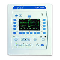
CPI CMP 200 DR Series Service Manual (307 pages)
X-RAY GENERATOR
Brand:
CPI
| Category:
Portable Generator
| Size: 5.98 MB
Table of Contents
Chapter 1 Pre-Installation
4
Table of Contents
4
Features
5
Generator Description
5
Introduction
5
Environmental Specifications
6
Radiographic Performance
6
Applicable Standards
7
Electromagnetic Compatibility (EMC)
11
Rohs Compliance
11
Safety
12
Safety and Warning Symbols
12
Safety Notices and Warnings
12
Safety Warning Labels
15
Generator Heat Output
19
Generator Power Requirements
19
Preparing for Installation
19
Generator Ground Requirements
23
Locating and Mounting the Generator
24
Cable Entrance and Seismic Center Location
25
Tools and Test Equipment Required
26
Generator Layout and Major Components
27
Pre-Installation Checklist
27
Compatibility Listing
30
Runtime License Agreement (Touchscreen Console)
31
Compatibility Statement
32
Customer Support
32
Chapter 2 Installation
34
Introduction
35
Removing the Generator Cover
35
Unpacking
35
Control Console
36
Equipment Placement
36
Main Cabinet
36
Major Component Layout
36
Anchoring the Generator to the Floor
38
Wiring to the Generator
38
Control Console
39
Hand Switch (Optional)
43
Stator Connections
43
Power Line Mains
45
Thermal Switch
45
High Tension Cables
47
X-Ray Tube Housing Ground
47
Emergency Power off / Power Distribution Relay
48
Low Speed Starter Tube Compatibility
48
Room Equipment
48
Safety Interlocks
48
Setting 120 / 240 VAC Boost Voltage
49
Low Speed Starter Tube Select Table
50
EPROM Type / Dual Speed Starter
52
Programming the Dual-Speed Starter
52
Setting Tube Type
52
Dual Speed Starter Tube Select Table
56
Auxiliary Transformer Line Voltage Tap Selection
64
Dip Switch Settings
64
Initial Run-Up
64
Initial Voltage Measurements
66
Final Checks
67
TUBE Ma AUTO CALIBRATION
67
Chapter 3C Interfacing and Programming
70
1.0 Introduction
72
2.0 Wiring to Inputs & Outputs
72
2.1 Inputs
72
2.2 Outputs
73
2.3 Inputs & Outputs (Simplified Schematic)
75
2.4 AEC Interconnect
76
2.5 DR Imaging System
76
3.0 Generator Programming
76
3.1 Entering into Programming Mode
76
4.0 Generator Setup Menu
78
5.0 Utility Menu
80
5.1 Setting Time and Date
81
5.2 Error Log
83
5.3 Statistics
85
5.4 Console
88
6.0 Apr Editor
91
7.0 Generator Configuration
93
7.1 Tube Selection / Tube Setup
93
7.2 Generator Limits
108
7.3 Receptor Setup
111
7.4 I/O Configuration
122
7.5 AEC Setup
130
7.6 AEC Calibration
135
7.7 Tube Calibration
135
8.0 Dap Printer Setup
137
9.0 Dap Interfacing
137
9.1 DAP Compatibility
137
9.2 DAP Installation
138
10.0 Dap Setup
139
10.1 DAP SETUP Menu
139
10.2
142
11.0 Dap Calibration
144
11.2 DAP Calibration Overview
144
3C11.1 Equipment Required
144
11.3 DAP Calibration Procedure
145
11.4 DAP Calculation Worksheet
148
12.0 Data Link
151
13.0 Touchscreen System Utilities
152
13.1 Accessing the Utilities Menu
153
13.2 APR Editor
155
13.3 APR Backup / Restore
161
13.4 Date / Time Setup
164
13.5 Receptor Symbols
166
13.6 Touchscreen Setup
168
13.7 Touchscreen Calibration
174
13.8 Data Link
175
13.9 Configuration Backup / Restore
176
13.10 Touchscreen Console Firmware Upgrade / Restore
179
13.11 Generator Configuration Backup and Restore
191
Chapterd Aec Calibration
194
AEC Board (Solid State Chambers)
196
Chapter 1 2.2
198
CHAPTER 3 AEC Board (Ion Chambers)
198
Chapter 4 2.3
200
AEC Board (Ion Chambers)
200
2.4
202
AEC Board (5-Field Ion Chambers)
202
Precalibration Notes
204
3.0
205
Short Aec Time Compensation
217
5.0 Aec Density Calibration
219
6.0 Aec Calibration (Wall Bucky)
224
Aec Calibration (Misc)
231
Film/Screen Response Vs
231
9.1
231
AEC Precalibration Checks
232
AEC Chamber Installation
232
Chapter 4 Acceptance Testing
234
Introduction
235
Required Test Equipment for Generator Verification
235
Acceptance Tests (Basic Functions)
236
Console Tests
236
Console Tests
237
Dual Speed Starter (Optional) Verfication
237
Low Speed Starter Verification
237
ACCEPTANCE TESTS (Kv, TIME, Ma and Mas)
238
Acceptance Tests (Aec)
241
Acceptance Tests (Dap)
241
Acceptance Tests (Dr Interface)
241
Acceptance Tests (Hvl, Linearity and Reproducibility)
241
Supplement Reproducibilty, Linearity, & Hvl Testing
242
Introduction
243
Equipment Setup
244
Reproducibility
244
Linearity
248
Evaluation
250
Troubleshooting
254
Introduction
255
Troubleshooting
255
Limit Messages
256
Operator Messages
256
Status and Error Codes
256
Erratic Console Faults
266
Error Messages
266
Dual Speed Starter Board
267
EMC Capacitor Board
267
Generator Control Board
267
HV Auxiliary Board
267
Led Indicators
267
AEC Board
268
Rev. B
269
Chapter 6 Regular Maintenance
270
Introduction
271
Maintenance Schedule
271
Oil Fill / Level Check
275
Cleaning
276
Console EPROM
277
Firmware Upgrade
277
Generator Firmware
277
Dual Speed Starter EPROM
278
Resetting Factory Defaults
278
Battery Replacement
279
Aec Board Remova Land Installation
280
Tube Conditioning / Seasoning
280
End of Product Life
281
Functional Drawings
307
Functional Schematic Index
307
Schematics
307
Use and Disclosure Is Subject to the Restrictions on the Title Page of this CPI Document
307
Advertisement
Advertisement
Related Products
CPI CMP 200
CPI CDM12K
CPI CDM6K
CPI CDMStar
CPI COTI
CPI CXB2
CPI CLS Advance
CPI CUMMINS ALLISON CA-200
CPI INDICO 100 Series
CPI Categories
Bank Note Validator
Amplifier
Cash Counters & Coin Sorters
Antenna
Scooter
More CPI Manuals
Login
Sign In
OR
Sign in with Facebook
Sign in with Google
Upload manual
Upload from disk
Upload from URL