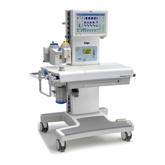
Dräger Perseus A500 Instructions For Use Manual
Anesthesia workstation
Hide thumbs
Also See for Perseus A500:
- Instructions for use manual (302 pages) ,
- Reprocessing instructions (48 pages) ,
- Quick manual (24 pages)

Related Manuals for Dräger Perseus A500


Summary of Contents for Dräger Perseus A500
- Page 1 Instructions for use Perseus A500 Anesthesia workstation WARNING To properly use this medical Software 2.0n device, read and comply with these instructions for use. Perseus A500...
- Page 2 This page has been left blank intentionally. Instructions for use Perseus A500 SW 2.0n...
-
Page 3: Table Of Contents
Activation of alarms after breath detection ..147 Preparation for a day of operations / after reprocessing ............ 63 Intelligent alarm behavior ........ 147 Selecting and connecting patient-specific accessories............67 Connecting or exchanging consumables..76 Instructions for use Perseus A500 SW 2.0n... - Page 4 Disposing of the device ........222 Disposing of accessories......... 222 Technical data..........223 General information......... 224 Ambient conditions .......... 224 Fresh-gas delivery........... 225 Fresh-gas delivery (electronically controlled gas mixer)............225 Fresh-gas delivery (mechanically controlled gas mixer)............226 Instructions for use Perseus A500 SW 2.0n...
-
Page 5: Information About This Document
(A) Letters in parentheses refer to elements in the related illustration. Use of terms Dräger uses the term "accessories" not only for The product "Perseus A500" is also referred to as accessories in the sense of IEC 60601-1, but also "Perseus". for consumables, removable parts, and attached parts. -
Page 6: Further Documents
NOTE A NOTE provides additional information intended to avoid inconvenience during operation. Instructions for use Perseus A500 SW 2.0n... -
Page 7: User Group Requirements
Service personnel This user group installs the product and performs the service activities. Service personnel has specialist knowledge in electrical and mechanical engineering and experience in the servicing of medical devices. Instructions for use Perseus A500 SW 2.0n... -
Page 8: For Your Safety And That Of Your Patients
Patient safety........... 10 Patient monitoring ........... 10 Electromagnetic compatibility (EMC) ....11 Training ............11 Keeping the instructions for use ...... 11 Product-specific safety information .... 12 Essential performance........13 Handling Infinity ID components...... 13 Instructions for use Perseus A500 SW 2.0n... -
Page 9: General Safety Information
– Bronchial suction personal injury and property damage. – Vaporizer – Manual resuscitator Perform the service in accordance with the – AGSS terminal unit chapter "Service". Instructions for use Perseus A500 SW 2.0n... -
Page 10: Patient Safety
The responsibility for selecting the best level of patient monitoring lies solely with the user of the medical device. Instructions for use Perseus A500 SW 2.0n... -
Page 11: Electromagnetic Compatibility (Emc)
– Observe the requirements for the WARNING electromagnetic environment. Observe the following section: "Electromagnetic Risk of operating errors environment" (page 251). The instructions for use must be kept in an accessible location for users. Instructions for use Perseus A500 SW 2.0n... -
Page 12: Product-Specific Safety Information
– Do not use substances containing alcohol. – Do not allow flammable or explosive substances to enter the breathing system or the breathing circuit. – Do not use cyclopropane or ether. Instructions for use Perseus A500 SW 2.0n... -
Page 13: Essential Performance
No intellectual property rights or any rights to the use of the medical device or RFID technology are hereby granted, either explicitly or implicitly, which are contrary to the above-mentioned conditions. Instructions for use Perseus A500 SW 2.0n... -
Page 14: Application
Application Application Intended use ..........15 Indications/Contraindications ...... 15 Indications ............15 Contraindications..........15 Further information on application ....16 Environments of use........16 Instructions for use Perseus A500 SW 2.0n... -
Page 15: Intended Use
– For patients suspected of malignant hyperthermia: Do not use any volatile anesthetic agent or Perseus with residual concentrations of these gases above 5 ppm. Instructions for use Perseus A500 SW 2.0n... -
Page 16: Further Information On Application
(e.g., magnetic resonance imaging). Also, do not use Perseus in the following environments: – Outside buildings – On intensive care units – During patient transport – In vehicles, airplanes, or helicopters Instructions for use Perseus A500 SW 2.0n... -
Page 17: Overview
Protocoling............34 Gas supply............34 Gas scavenging..........34 Data exchange, interfaces....... 35 Gas flow plan ..........36 Breathing system..........36 Gas supply (electronically controlled gas mixer)............... 37 Gas supply (mechanically controlled gas mixer)............... 38 Instructions for use Perseus A500 SW 2.0n... -
Page 18: Hardware
D Drawer or pull-out writing tray with lockable compartment (optional) E Central brake F Castors with central brake G Footrest H Trolley Anesthetic gas receiving system with flow indicator J CO absorber K APL valve L External fresh-gas outlet (optional) Instructions for use Perseus A500 SW 2.0n... -
Page 19: Front (Ceiling-Mounted Version)
D Key for switching the workplace illumination on and off and dimming the illumination intensity in 3 steps (dark, medium, and bright) E Key for turning the device on or off Instructions for use Perseus A500 SW 2.0n... -
Page 20: Plug-In Connection With Vapor View Option For Up To 3 Vaporizers
Overview Plug-in connection with Vapor View option for up to 3 vaporizers The version for 2 vaporizers is shown here: A Sensor unit B Illumination unit Instructions for use Perseus A500 SW 2.0n... -
Page 21: Breathing System
Only use the pressure gauge as the primary source of information if the pressure indicator on the status display has failed. C Collecting channel D Inspiratory port Instructions for use Perseus A500 SW 2.0n... -
Page 22: Side View From Left
Overview Side view from left A GCX rail for mounting additional workstation components B Strain relief for AGS hose, adjustable height C External fresh-gas outlet (optional) Instructions for use Perseus A500 SW 2.0n... -
Page 23: Device Column
D Screw for closing the cable channel lid E Tabs to hold the cable F Cable channel On the ceiling-mounted version, there is a compartment located under the column cover for stowing accessories, e.g., a cable. Instructions for use Perseus A500 SW 2.0n... -
Page 24: Rear (Trolley Version)
(available for the trolley version only) D Connection for optional pole (38 mm) E Castor with castor brake F Gas cylinder holders (optional) with hook-and-loop strap (available for the trolley version only) G Interfaces H Rating plate Instructions for use Perseus A500 SW 2.0n... - Page 25 D Connection for optional pole (38 mm) E Castor with castor brake F Gas cylinder holders (optional) with hook-and- loop strap (available for the trolley version only) G Interfaces H Rating plate Instructions for use Perseus A500 SW 2.0n...
-
Page 26: Rear (Ceiling-Mounted Version)
Overview Rear (ceiling-mounted version) Differences from the trolley version: A Mounting interface for docking to the ceiling supply unit Instructions for use Perseus A500 SW 2.0n... -
Page 27: Interfaces
B Serial interfaces (COM 1 and COM 2) C USB interface D Network interface E Interface for workstation light (optional) F IEC connector (socket for power cable) G Potential equalization pin H Collecting channel Instructions for use Perseus A500 SW 2.0n... -
Page 28: Gas Inlets
Gas inlets A Connections for gas pressure measurement for gas cylinders (optional) B Connections for central gas supply O optional) C Connections for external gas cylinders (optional) D Advanced Cylinder Support label (if present) Instructions for use Perseus A500 SW 2.0n... -
Page 29: Hanger Yokes (Optional) For Gas Cylinders With
Hanger yokes (optional) for gas cylinders with pin-index connections A Hanger yokes (optional) for gas cylinders with pin-index connections B Wrench for opening and closing the gas cylinder valves C Advanced Cylinder Support label (if present) Instructions for use Perseus A500 SW 2.0n... -
Page 30: Auxiliary Power Sockets (Trolley Version)
Overview Auxiliary power sockets (trolley version) View with column cover removed: A Auxiliary power sockets, depending on equipment variant B Isolation transformer switch (optional) C Circuit breakers or fuses, depending on equipment variant Instructions for use Perseus A500 SW 2.0n... -
Page 31: Gas Mixing Unit (Electronically Controlled)
21 + key (O flush) Symbols for mains power supply and power supply from internal battery J Symbols for gas supply (O , Air, N O) through central supply and gas cylinders Instructions for use Perseus A500 SW 2.0n... -
Page 32: Gas Mixing Unit (Mechanically Controlled)
J Symbols for mains power supply and power supply from internal battery K Symbol for programmed Auto On L Current time or time for Auto On Explanation of the symbols which may be displayed, see page 277. Instructions for use Perseus A500 SW 2.0n... -
Page 33: Functional Scope
– Inspiratory anesthetic gas concentration – Inspiratory O concentration – Inspiratory and expiratory CO concentrations – Apnea (pressure, flow, and CO – Occurrence of anesthetic gas mixtures – Degree of filling of the breathing bag Instructions for use Perseus A500 SW 2.0n... -
Page 34: Display On The Screen
– Set values and their changes – Patient data – Ventilation modes – Events (e.g., alarms, confirmed alarms, switch- on time and switch-off time) – Test results – Gas consumption and anesthetic agent consumption Instructions for use Perseus A500 SW 2.0n... -
Page 35: Data Exchange, Interfaces
NTP server. For more information, see "Connections to IT networks" on page 253. Infinity ID accessory support – Exchange interval monitoring – Anti-interchange security for breathing hoses For more information, see page 269. Instructions for use Perseus A500 SW 2.0n... -
Page 36: Gas Flow Plan
F Patient G Expiratory pressure measurement H Patient gas measurement module Expiratory valve J PEEP/Pmax valve K APL valve L Anesthetic gas receiving system M Changeover between automatic ventilation and Manual / Spontaneous Instructions for use Perseus A500 SW 2.0n... -
Page 37: Gas Supply (Electronically Controlled Gas Mixer)
Gas supply (electronically controlled gas mixer) Add. O Aux. O A Gas supply (central supply or gas cylinders) B Gas mixer C Vaporizer flowmeter switch flush G Switch-over valve H Breathing system External fresh-gas outlet (optional) Instructions for use Perseus A500 SW 2.0n... -
Page 38: Gas Supply (Mechanically Controlled Gas Mixer)
Gas supply (mechanically controlled gas mixer) Aux. O A Gas supply (central supply or gas cylinders) B Flow control valves C Minimum O delivery D Total flow tube E Vaporizer flush flowmeter H Breathing system Instructions for use Perseus A500 SW 2.0n... -
Page 39: Operating Concept
Operating the flow control valves ....44 Remote control for the ceiling-mounted version (combination with Dräger ceiling supply units) ..........44 Releasing the locking brakes......44 Height adjustment..........45 Status display ..........45 Safety sensor ..........45 Instructions for use Perseus A500 SW 2.0n... -
Page 40: Screen
E Buttons to expand and shrink the therapy bar. Information regarding configurable fields, see F Field with additional information: page 173. – Additional and calculated set values – Spontaneous breathing activity of the patient Instructions for use Perseus A500 SW 2.0n... -
Page 41: Dialog Windows
(D). This window can be opened by touching the corresponding parameter field in the monitoring area. In the event of an alarm, the window can be opened automatically, see page 155. Instructions for use Perseus A500 SW 2.0n... -
Page 42: Color Concept
In the flow waveform, spontaneous breathing and ment: pressure support are displayed in a light brown currently not color. available, func- tion activated Measured values whose specified accuracy cannot be maintained are displayed in dark gray. Gray Unavailable element Instructions for use Perseus A500 SW 2.0n... -
Page 43: Selecting And Setting
In the following chapters of this document, this sequence of action is represented by simplified – Selecting a view explanations: – Deactivating the CO alarms. – "Set the value." – "Touch the button." Instructions for use Perseus A500 SW 2.0n... -
Page 44: Remote Control For The Ceiling-Mounted Version
– Prevent accidental activation of the A Key (green) to release the brake on the ceiling remote control, e.g., by objects. bearing B Key (blue) to release the brake on the intermediate bearing Instructions for use Perseus A500 SW 2.0n... -
Page 45: Safety Sensor
To continue lowering the ceiling supply unit after the safety sensor has triggered, perform the following steps: 1 Briefly lift the anesthesia machine using the ceiling supply unit. 2 Make sure that no obstacles are present. Instructions for use Perseus A500 SW 2.0n... -
Page 46: Assembly And Preparation
Mounting the flexible arm (optional) or the bag elbow ............... 67 Selecting and connecting patient-specific accessories ............ 67 Safety information ........... 67 Fitting the breathing circuit and the filters..68 Breathing bag ..........71 Instructions for use Perseus A500 SW 2.0n... -
Page 47: Perseus As A Ceiling-Mounted Version
Before using Perseus, make sure that the cable connection has been established. Establish the cable connection between Perseus and the ceiling supply unit. Observe the instructions for use of the ceiling supply unit. Instructions for use Perseus A500 SW 2.0n... -
Page 48: Combination With Other Ceiling Supply Units
Perseus can be mounted. Dräger will provide the manufacturer of the ceiling supply unit with the document "Perseus A500 anesthesia workstation - ceiling-mounted version - interface description for ceiling supply units". The instructions in this document must be followed during construction. -
Page 49: Mounting Of Accessories
Arm weight (B1) + weight of attached compo- (15.7 in) (33 lbs) (18.7 lbs) nent (B2) 570 mm 15 kg 8.5 kg Product of distance and weight (22.4 in) (33 lbs) (18.7 lbs) Instructions for use Perseus A500 SW 2.0n... -
Page 50: Mounting On The Mounting Rails
Check the tilting stability. accessories still applies as for the ceiling- mounted version. – Pay attention to the maximum weight of the accessories. – Pay attention to the distribution of the weight. Instructions for use Perseus A500 SW 2.0n... - Page 51 Perseus may fall off. The mechanical coupling and uncoupling of Perseus and the flexibility trolley must only be performed by specialized service personnel. Instructions for use Perseus A500 SW 2.0n...
-
Page 52: Before First Operation
6 Set the main switch to position I, see page 27. 2 Lay the power cable in the cable conduit on the right side of the device. Instructions for use Perseus A500 SW 2.0n... -
Page 53: Charging The Battery
1 Connect the power cable of the additional device to an auxiliary power socket. 2 For Perseus with isolation transformer: Switch on the power for the isolation transformer and the auxiliary power sockets using the isolation transformer switch. Instructions for use Perseus A500 SW 2.0n... -
Page 54: Establishing Potential Equalization
If these components are placed – Do not connect USB devices by means of under the column cover, they may overheat. charger cables. Do not place components that become warm under the column cover. Instructions for use Perseus A500 SW 2.0n... - Page 55 – Only make connections to data interfaces with permission from the responsible organization (IT representative and the hospital equipment officer). – Follow the information in the chapter "Connections to IT networks". Instructions for use Perseus A500 SW 2.0n...
-
Page 56: Intrahospital Transport
6 Push the optional drawers in. WARNING 7 Lock the lockable optional drawers. Risk of injury The device may tip over when it is transported over inclines. Always move the device using two people. Instructions for use Perseus A500 SW 2.0n... -
Page 57: Establishing The Gas Supply
Risk of fire Ignition sources in combination with oxygen can lead to fires. Do not position oxygen sources in the vicinity of ignition sources, e.g., electrical connectors. Instructions for use Perseus A500 SW 2.0n... -
Page 58: Central Gas Supply
ISO 80601-2-13 which allows the pressure indicator to be read from the user's operating location at the front. Do not connect central supply hoses to the connectors for external gas cylinders. Instructions for use Perseus A500 SW 2.0n... - Page 59 2 Connect the pressure measurement lines to the connectors (B) above the gas inlets. 3 Set the full gas cylinders (C) into the gas cylinder holders and secure them with the hook-and-loop straps. Instructions for use Perseus A500 SW 2.0n...
- Page 60 12 Tighten the handle (H) on the cylinder holder (I). 13 Secure the gas cylinders (F) with hook-and- loop straps (K). If required, the gas cylinder valve (C) can be opened with the supplied wrench (G). Instructions for use Perseus A500 SW 2.0n...
-
Page 61: Fitting The Vaporizers
0 position. Repeat the test independent gas measurement system complying with the other vaporizer. with ISO 80601-2-55 must be used. 6 Set both control dials to position 0. Instructions for use Perseus A500 SW 2.0n... -
Page 62: Ensuring The Gas Scavenging
Perseus is equipped with an integrated anesthetic gas receiving system (AGS). 1 Connect the scavenging hose to the nozzle (A) on the receiving system. 2 Secure the scavenging hose with the strain relief (B). Instructions for use Perseus A500 SW 2.0n... -
Page 63: Preparation For A Day Of Operations / After Reprocessing
– Incident flow meshes in the inspiratory limb 1 Insert the TurboVent 2 blower module (A) into of the lower part of the breathing system the breathing system mount. housing and in the expiratory port – Seals and sealing rings Instructions for use Perseus A500 SW 2.0n... - Page 64 When fitting, take care that the lower dot is facing the user during operation. Perform the following steps for non-return valves (C) and (D): 1 Align the valves correctly. 2 Insert the valves. Instructions for use Perseus A500 SW 2.0n...
- Page 65 1 Insert flow sensors (J) and (L). 2 Insert the inspiratory port (K) and screw it tight with the knurled nut. 3 Insert in the expiratory port (M) and screw it tight with the knurled nut. Instructions for use Perseus A500 SW 2.0n...
-
Page 66: Inserting The Breathing System
3 Set the breathing system cover (C) into place 4 Screw on the CLIC adapter. and click it into position. Inserting the breathing system 1 Insert the assembled breathing system (A) vertically into the breathing system mount. Instructions for use Perseus A500 SW 2.0n... -
Page 67: Selecting And Connecting Patient-Specific Accessories
– Use a coaxial test adapter to check the inner hose for leakage, see page 125. Next, perform a leakage test on the entire breathing circuit. – Monitor the measured gas concentrations during ventilation. Instructions for use Perseus A500 SW 2.0n... -
Page 68: Fitting The Breathing Circuit And The Filters
ID functionality of the Infinity ID breathing switching on the system, hose compliance and hoses cannot be used. hose resistance will automatically be adopted when Infinity ID breathing hoses are connected. Instructions for use Perseus A500 SW 2.0n... - Page 69 70, "Table with recommended hose configurations". When attaching or removing the breathing hoses, always hold them at the connection sleeve and not at the spiral ribbing. Instructions for use Perseus A500 SW 2.0n...
- Page 70 When fine pored filters (A) are used, do not connect the sample line between the tube and the filter: When no filters, but only an HME (B) is in use, set the alarm limits for MV low and Paw high to suitable values: Instructions for use Perseus A500 SW 2.0n...
-
Page 71: Breathing Bag
To allow the bag to unfold freely, place it to the right over the hose holder so that it is not obstructed by cables or breathing hoses. Instructions for use Perseus A500 SW 2.0n... -
Page 72: Observing Resistance And Compliance
The resistance values given in the instructions for use for the accessories must therefore be subtracted from the inspiratory resistance of the breathing system. Instructions for use Perseus A500 SW 2.0n... - Page 73 – Changing the configuration of breathing hoses and accessories that carry gases during the expiratory time It is the responsibility of the user of the medical device to select the most suitable remedial measure. Instructions for use Perseus A500 SW 2.0n...
-
Page 74: Connecting A Non-Rebreathing System (Optional)
Risk of faulty gas delivery and CO and any anesthetic gases must also be monitored for non-rebreathing systems. The sample line must be connected to the elbow and the water trap on the anesthesia machine. Instructions for use Perseus A500 SW 2.0n... - Page 75 AGS (C). CAUTION Risk due to open AGS inlet nozzle After using a non-rebreathing system, reinsert the sealing plug into the inlet nozzle to prevent contamination of the ambient air with anesthetic gases. Instructions for use Perseus A500 SW 2.0n...
-
Page 76: Connecting Or Exchanging Consumables
Risk of chemical burns sealing rings on the absorber insert. Soda lime is caustic and is a strong irritant for eyes, skin, and airway. Handle this absorption material carefully and do not spill it. Instructions for use Perseus A500 SW 2.0n... -
Page 77: Water Trap
Risk of infection The water trap may contain infectious fluid. – Proceed carefully when emptying and take protective measures if necessary. – Follow the infection prevention policies and reprocessing regulations of the healthcare facility. Instructions for use Perseus A500 SW 2.0n... -
Page 78: Connecting The Sample Line
As a result, the gas measurement will not display correct values. When attaching the sample line, make sure not to attach it incorrectly. Instructions for use Perseus A500 SW 2.0n... -
Page 79: Getting Started
Getting started Turning on Perseus ........80 Checking the device configuration ....81 Checking the operational readiness .... 81 Emergency start-up ........82 Electronically controlled gas mixer ....82 Mechanically controlled gas mixer....82 Instructions for use Perseus A500 SW 2.0n... -
Page 80: Turning On Perseus
Prevent this by actuating the central brake or the castor brakes and check their function. WARNING Risk of device malfunction Some safety systems are only checked during start-up. Restart Perseus at least once per month to maintain proper functionality. Instructions for use Perseus A500 SW 2.0n... -
Page 81: Checking The Device Configuration
System is operational with limita- tions. There are functional restrictions. Take further measures to ensure patient safety (e.g., external moni- toring). System is not operational. Call service personnel. Gray The system has not been tested. Instructions for use Perseus A500 SW 2.0n... -
Page 82: Emergency Start-Up
8 As soon as the Standby page is displayed, start the therapy, see page 87. 9 Set the O switch (C) to Aux. O to stop the increased fresh-gas flow. 10 Close the flow control valve (B). Instructions for use Perseus A500 SW 2.0n... -
Page 83: Operation
Ending the therapy ........116 Volumeter ............104 Switching to the Standby mode....... 116 Low-flow wizard (optional) ....... 104 insufflation........116 Using O Organizing the screen display...... 105 Available views ..........105 Changing the current view....... 105 Instructions for use Perseus A500 SW 2.0n... - Page 84 Operation Change of patient .......... 118 Cleaning and disinfecting the workstation ..118 Checking or replacing consumables ....118 Checking the device ........118 Flushing the breathing system ......118 Instructions for use Perseus A500 SW 2.0n...
-
Page 85: Safety Information
Misdiagnosis or misinterpretation of the measured values or other parameters can endanger the patient. Do not make therapeutic decisions based solely on individual measured values and monitoring parameters. Therapeutic decisions must be made solely by the user. Instructions for use Perseus A500 SW 2.0n... - Page 86 Due to the technical characteristics of gas Take care that this does not happen measurements, the measured gas values might unintentionally. be inaccurate at high respiratory rates and at certain I:E ratios. Observe the technical data. Instructions for use Perseus A500 SW 2.0n...
-
Page 87: Starting The Therapy
150. The set value for Ti is set automatically based on RR so that the I:E ratio set in the start settings are the result, see 158. Instructions for use Perseus A500 SW 2.0n... -
Page 88: Checking The Patient Data
Always set patient age correctly. flow FG flow. This restriction depends on the set tidal volume VT and the set respiratory rate Adjust patient data (A) if necessary. Instructions for use Perseus A500 SW 2.0n... -
Page 89: Useful Tips
The use of minimum-flow or low-flow settings can lead to accumulation of metabolic by-products in the breathing system. When using minimum-flow setings or low-flow settings follow the recommendations of professional societies (e.g., regular flushing of the breathing system). Instructions for use Perseus A500 SW 2.0n... -
Page 90: Adjusting The Therapy
Set the APL valve to the desired maximum airway pressure. The patient can be manually ventilated with the breathing bag. The pressure is limited by the set value. Instructions for use Perseus A500 SW 2.0n... -
Page 91: Adjusting The Fresh-Gas Flow
– In automatic ventilation, permanently pressing the O flush may result in a slight rise of the PEEP level. However, this rise has no effect on the peak pressure. Instructions for use Perseus A500 SW 2.0n... -
Page 92: Changing The Ventilation Mode
2 As needed, the expanded therapy bar can be "Ventilation modes and effective parameters" displayed using the More buttons (C) or (D); starting on page 260. here, additional parameters (Trigger, ∆Psupp, etc.) can be adapted to the patient. Instructions for use Perseus A500 SW 2.0n... -
Page 93: Special Forms Of Therapy
Properties of CBM mode: – All gas concentrations are measured independent of the respiratory phase. – The CO apnea and pressure apnea alarms are inactive. The CBM mode can be used in all active ventilation modes. Instructions for use Perseus A500 SW 2.0n... -
Page 94: Only Gas Concentration Measurement/Use Of Monitoring
Use this operating mode for regional anesthesia or short pauses in therapy, such as disconnection or intubation, to reduce contamination of the ambient air with anesthetic gases due to an open Y-piece. Instructions for use Perseus A500 SW 2.0n... -
Page 95: Maneuvers (Optional)
(B). Perseus will trigger an extended breath or will extend an already triggered automatic breath. Instructions for use Perseus A500 SW 2.0n... -
Page 96: One-Step Recruitment
If the alarm limit is too low, it is changed to a value 5 hPa above the set pressure. After the maneuver, the alarm limit is reset to its original value. Instructions for use Perseus A500 SW 2.0n... -
Page 97: Multi-Step Recruitment
5 hPa above the set pressure. therapy controls, set the pressures that are to After the maneuver, the alarm limit is reset to its be reached during the maneuver. original value. Instructions for use Perseus A500 SW 2.0n... - Page 98 (K) and move the cursor with the rotary knob. To facilitate reading the data, screen area (K) will temporarily not be updated. To show the current measured values again, touch area (L). Instructions for use Perseus A500 SW 2.0n...
-
Page 99: Alarm Behavior During The Maneuvers
Apnea (no flow) Stopped Apnea (no CO Apnea 1) Existing alarms are preserved. No new alarms will be issued. Some technical alarms stop the maneuver automatically, e.g., alarms caused by a sensor failure. Instructions for use Perseus A500 SW 2.0n... -
Page 100: Using Fields With Special Functions
The integrated MAC algorithm is based on the MAC values shown in the following table. These values are guiding values only. The binding values are specified on the package information leaflet of the anesthetic agent. 1) 40 years Instructions for use Perseus A500 SW 2.0n... -
Page 101: Prediction Of The Anesthetic Gas Concentration (Optional)
These restrictions in the patient data result from expiratory anesthetic gas concentration the scientific models all calculations are based on. B Section for the prediction C Current vaporizer setting D Prediction curve ("what if..." function) E xMAC scale Instructions for use Perseus A500 SW 2.0n... -
Page 102: Prediction Of The Inspiratory O (Optional)
The FiO prediction parameter field must be configured in the monitoring area. The FiO prediction is suitable only for patients with a body weight of more than 30 kg (66 lbs). Instructions for use Perseus A500 SW 2.0n... -
Page 103: Econometer (Optional)
3 To reset the countdown to zero, touch the Reset button (A). An insufficiently filled breathing bag can trigger the Fresh gas low or leakage or Emergency air inlet activated alarms, for example. Instructions for use Perseus A500 SW 2.0n... -
Page 104: Volumeter
60 seconds. The measured values are displayed An insufficient fresh-gas flow may trigger the for 4 minutes and then deleted. Fresh gas low or leakage or Emergency air inlet activated alarms, for example. Instructions for use Perseus A500 SW 2.0n... -
Page 105: Organizing The Screen Display
1 2 3 Touch the View button. 1 2 3 The screen displays the first view Two buttons are available for changing the current view: – Views... button 1 2 3 – View button Instructions for use Perseus A500 SW 2.0n... -
Page 106: Customizing The Current View
Restoring the current view The changes in the current view can be reset to the saved standard. 1 Open the Views dialog window. 2 Touch the Restore current view button. Instructions for use Perseus A500 SW 2.0n... -
Page 107: Displaying Mini-Trends
Displaying alarm limits and units of measurement The alarm limits and the units of measurement can also be displayed in the waveform and parameter fields. 1 Open the Views dialog window. 2 Touch the Limits & units button. Instructions for use Perseus A500 SW 2.0n... -
Page 108: Displaying Additional Data
The vertical tabs (B) display different combinations of parameters. Trends/Data Use the rotary knob or the arrow buttons to scroll the cursor (B) up (C) or down (D) in the logbook. To scroll quickly, touch the gray area (E). Instructions for use Perseus A500 SW 2.0n... -
Page 109: Trends
Consumption, the gas consumption levels can be – Zoom - reset to zero, see page 170. Displaying the standard time period and the current point in time: Touch the Reset zoom button (E). Instructions for use Perseus A500 SW 2.0n... -
Page 110: Setting The Sound Volume
Setting via the Quick setup window 1 Touch the respective waveform or parameter field. The Quick setup window opens. 2 Set the upper alarm limit (A). 3 Set the lower alarm limit (B). Instructions for use Perseus A500 SW 2.0n... -
Page 111: Activating Or Deactivating Co
The lower alarm limit for the xMAC level is also adjusted during automatic setting, see page 112. Configuration and algorithm, see page 154. Instructions for use Perseus A500 SW 2.0n... -
Page 112: Automatic Xmac Monitoring
(D or G), Perseus generates the xMAC low alarm with low priority. If the alarm is not acknowledged with the ALARM RESET button, the priority is raised to medium priority after 60 seconds. Instructions for use Perseus A500 SW 2.0n... -
Page 113: Changing The Patient Data
The screen contents can be exported to a USB – Trends flash drive as a screenshot. Touch the Export screenshot button in the main menu bar. The screenshot will be saved as a ".png" file. Instructions for use Perseus A500 SW 2.0n... -
Page 114: Other Settings
When the breathing system warmer is switched off, do not make therapy decisions solely on the 3 To switch the warmer on or off, touch the basis of the displayed values for flow and corresponding button (B). volume. Instructions for use Perseus A500 SW 2.0n... -
Page 115: Creating Additional Logbook Entries
Changes made in the System setup dialog window during operation can be reset to the start settings. 1 Open the System setup dialog window. 2 Open the corresponding dialog window. 3 Touch the System defaults button and confirm. Instructions for use Perseus A500 SW 2.0n... -
Page 116: Ending The Therapy
– When O outlets are in use (e.g., for insufflation), do not use any ignition sources in the immediate vicinity. – Do not position oxygen sources in the vicinity of ignition sources, e.g., electrical connectors. Instructions for use Perseus A500 SW 2.0n... - Page 117 Aux. O position (C). Beginning O insufflation Open the flow control valve (B) of the flowmeter. Ending O insufflation Close the flow control valve (B) of the flowmeter. Instructions for use Perseus A500 SW 2.0n...
-
Page 118: Change Of Patient
4 After the end of flushing, the device switches to 2 When no filter is used, replace the sample line Standby mode. and dispose of used sample lines. If necessary, end the flushing prematurely with Cancel. Instructions for use Perseus A500 SW 2.0n... - Page 119 Risk of impaired ventilation due to faulty drying function The breathing system and breathing hoses may still retain traces of moisture even after the flushing and drying functions are performed. Check the breathing system and breathing hoses for condensate. Instructions for use Perseus A500 SW 2.0n...
-
Page 120: Tests
System test and leakage test ......123 Leakage assistant ........... 124 Completing the checklist ......126 Prerequisites ........... 126 Vaporizers ............127 Gas flow ............128 Breathing circuit..........130 Valves.............. 130 Components ............ 131 Accessories ............. 132 Instructions for use Perseus A500 SW 2.0n... -
Page 121: Information On The Availability Of Individual Device Functions
Perform the system test every day. If the system is connected. test is canceled during execution, perform it again as soon as possible. Instructions for use Perseus A500 SW 2.0n... -
Page 122: Available Test Types
– Leakage test of the inner hose of a suspected connected Dräger coaxial breathing circuit. Use the coaxial test adapter – If coaxial breathing cir- for this. For more information, see cuits are used page 124. Instructions for use Perseus A500 SW 2.0n... -
Page 123: Performing The Tests
System test - do not connect patient. The test progress is displayed in area (G) while the automatic test is running. All test results are 2 Complete the checklist (A), see page 126. displayed in area (H). Instructions for use Perseus A500 SW 2.0n... -
Page 124: Leakage Assistant
– With mechanically controlled gas mixer: All flow control valves are closed. – The vaporizers are closed. – The breathing circuit is correctly connected. – The APL valve is set to 30. Instructions for use Perseus A500 SW 2.0n... - Page 125 6 Fully connect the breathing circuit. – Remove the coaxial test adapter. – Plug in the elbow again. – Connect the connector (E) (expiration) to the expiratory port. – Perform the system test or the leakage test. Instructions for use Perseus A500 SW 2.0n...
-
Page 126: Completing The Checklist
Prerequisites 4 Close all the flow control valves. 5 Set the O switch to Aux. O 1 Connect the hoses (A). 2 Seal the Y-piece (B). 3 Set the APL valve to 30. Instructions for use Perseus A500 SW 2.0n... -
Page 127: Vaporizers
1 The locking lever points left, indicating the vaporizer is locked. 3 The control dial is set to position 0 and the key is locked in placed. 4 The filling inlet is closed. Instructions for use Perseus A500 SW 2.0n... -
Page 128: Gas Flow
(optional), and low-flow wizard – Inaccuracy in the FiO prediction – Inaccurate volume delivery in volume- controlled ventilation modes – Accumulation of argon in low-flow operation and minimal-flow operation Do not use any O concentrators. Instructions for use Perseus A500 SW 2.0n... - Page 129 2 Repeat the settings for the Air and N O flow control valves. 3 Close all the flow control valves. The breathing bag fills and the inflow of gas is audible. Instructions for use Perseus A500 SW 2.0n...
-
Page 130: Breathing Circuit
NOTE Do not change the length of flex hoses after the test is done. 1 Press the O + key and keep it pressed until the pressure exceeds 15 hPa. Instructions for use Perseus A500 SW 2.0n... -
Page 131: Components
Bronchial suction The breathing bag fills and the inflow of gas is audible. Check the functional integrity of the bronchial suction. 2 Lift the APL valve. The pressure is released. Instructions for use Perseus A500 SW 2.0n... -
Page 132: Accessories
When Infinity ID functionality is not configured: – Absorbers will not be detected, e.g., reusable CO absorbers Update the exchange date manually: Touch the Reset button after the soda lime has been replaced. Instructions for use Perseus A500 SW 2.0n... - Page 133 Do not leave the flow control valves open Connect the sample line. unnecessarily long. NOTE Only perform leakage tests with CLIC absorber locked into place because this affects the system compliance values. Instructions for use Perseus A500 SW 2.0n...
- Page 134 When Infinity ID functionality is not configured: – Water traps will not be detected. Update the exchange date manually: Touch the Reset button after a new water trap has been installed. Instructions for use Perseus A500 SW 2.0n...
-
Page 135: Ending Operation
End of operation ..........136 Programming the system test (Auto On option) ................ 136 Flushing and drying the breathing system (Flush & Dry function)........137 Storing the device..........137 Disconnecting the mains power supply ... 137 Instructions for use Perseus A500 SW 2.0n... -
Page 136: Turning Off The Device
31. For a final test of the operational readiness of the For more information, see page 165. device, it is only necessary to perform some brief manual checks after the automatic system test. Instructions for use Perseus A500 SW 2.0n... -
Page 137: Flushing And Drying The Breathing System (Flush & Dry Function)
1 Set the main switch to position 0. 2 Disconnect from mains power supply if necessary. Disconnecting the mains power supply Pull out the mains plug. On the ceiling-mounted version, the corresponding cable is labeled with Perseus. Instructions for use Perseus A500 SW 2.0n... -
Page 138: Alarms
) alarm ....144 Resetting the Apnea (no CO Alarm delay and alarm escalation....144 Activation of alarms after breath detection. 147 Intelligent alarm behavior ......147 Combined alarms ..........147 Suppressed alarms ......... 147 Instructions for use Perseus A500 SW 2.0n... -
Page 139: Displaying Alarms
Dräger Vapor 3000 if their cause can be remedied by adjusting or refilling the vaporizer, for example: – Inspiratory xMAC high – Filling level of vaporizer low – Vaporizer open – xMAC low Instructions for use Perseus A500 SW 2.0n... -
Page 140: Response To Alarms
"Troubleshooting", see page 191 Open the Alarms dialog window and touch the Current alarms tab (A). Alarms 2 In the list (B), touch the corresponding alarm or select it with the rotary knob. Instructions for use Perseus A500 SW 2.0n... -
Page 141: Suppressing The Alarm Tone
Remedy" on page 191 by the following remedial messages: After an alarm is downgraded, the respective priority rating is maintained , see table "Alarm – Cause – Remedy" on page 191. Instructions for use Perseus A500 SW 2.0n... -
Page 142: Opening The Alarm History
To do so, either set the alarm limits, see page 110, or change the alarm limits via the Quick setup window. Instructions for use Perseus A500 SW 2.0n... -
Page 143: Adopting Alarm Settings When Changing The Ventilation Mode
MV low page 156 page 156 Apnea (no flow) Apnea (no pres- sure) 1) This alarm is only activated when the MV low alarm limit is also activated. Instructions for use Perseus A500 SW 2.0n... -
Page 144: Alarm Delay And Alarm Escalation
15 seconds Inspiratory N O high After two successive inAgent low respiratory phases and 15 seconds After two successive respiratory phases and 15 seconds after 30 seconds if no respiratory phases are detected Instructions for use Perseus A500 SW 2.0n... - Page 145 At the latest after 20 seconds (15 seconds for RRmin Apnea Ventilation ≥ (configurable, see page 155) No CO detected >60 s Inspiratory tidal volume high After 3 successive Tidal volume not achieved breaths Instructions for use Perseus A500 SW 2.0n...
- Page 146 O measurement not available Agent measurement not avail- able measurement temporarily inaccurate sensor accuracy low >20 s Agent measurement temporar- ily inaccurate O measurement temporarily inaccurate Measured gas concentrations temporarily inaccurate Instructions for use Perseus A500 SW 2.0n...
-
Page 147: Activation Of Alarms After Breath Detection
If this measurement function monitors physiological parameters, alarms based on these parameters will not be generated. Example: Fault Displayed alarm Non-generated alarm measurement is faulty Sample line occluded Apnea (no CO Instructions for use Perseus A500 SW 2.0n... -
Page 148: Configuration
172 Entering the activation code ......172 Activating the licensed software option ... 172 Overview of configurable screen contents . 173 Waveforms and associated parameter fields .. 173 Parameter fields ..........174 Instructions for use Perseus A500 SW 2.0n... -
Page 149: Device Settings
For more information, see page 164. Standby Perseus can adopt the time from a network or from a device connected via MEDIBUS. The time synchronization takes place shortly after switch-on and at regular intervals thereafter. Instructions for use Perseus A500 SW 2.0n... -
Page 150: Defining The Start Settings
(view 3) Default view 1 Standard; 2 Expert; 3 Expert Specify the standard view. Save as system Current view Save current screen layout. defaults (only available during operation) All views Save all screen layouts. Instructions for use Perseus A500 SW 2.0n... - Page 151 Specify coordinate axes for flow/volume loop display. Vertical tab "Colors" Setting range Headline/ Description Parameter Default color; color palette with 7 additional Specify parameter colors. Paw; colors Flow, volume Default color; ISO color Agent Instructions for use Perseus A500 SW 2.0n...
-
Page 152: System Setup > Alarms
PEEP. 0.10 to 9.95 0.10 to 9.95 0.10 to 9.95 Sevoflurane inSev 4.40 5.10 6.70 [%]; [kPa] Off; Off; Off; inSev 0.00 to 9.85 0.00 to 9.85 0.00 to 9.85 [%]; [kPa] Instructions for use Perseus A500 SW 2.0n... - Page 153 Description Parameter Alarm tone volume 10 to 100 Set the alarm tone volume. Minimum alarm tone 10 to 100 Set the minimum volume with volume which an alarm tone will be sig- naled. Instructions for use Perseus A500 SW 2.0n...
- Page 154 (optional) and Pause), a further 20 percentage points are added to the configured value. VTi + [%] Off; 20 to 80 The setting for this parameter has no effect in volume-controlled ven- tilation modes. Instructions for use Perseus A500 SW 2.0n...
- Page 155 Pause mode has expired. Default value for 0:30 to 02:00 0:30 to 02:00 0:30 to 02:00 Specify default time for Pause. "Timer" [mm:ss] 2:00 1:00 0:30 Instructions for use Perseus A500 SW 2.0n...
- Page 156 [psi]: Off; 218 to 725 ders. [bar]; [kPax100]: Off; 15 to 50 [psi]: Off; 218 to 725 [bar]; [kPax100]: Off; 15 to 40 [psi]: Off; 218 to 580 Instructions for use Perseus A500 SW 2.0n...
-
Page 157: System Setup > Therapy
The following applies in volume-controlled modes: minimal: 2.0 L/min MV low = VT x RR x (1 – offset); VTi high = 130 % x VT minimal: 0.3 L/min VTi high = VT x (1 + offset) Instructions for use Perseus A500 SW 2.0n... - Page 158 1:50 to 50:1 1:2.0 1:2.0 1:1.0 %Tplat 0 to 60 0 to 60 0 to 60 Trigger 0.3 to 15 0.3 to 15 0.3 to 15 [L/min] Sync. On; Off On; Off On; Off Instructions for use Perseus A500 SW 2.0n...
- Page 159 One-step recruitment or Multi-step recruitment maneuver, a reminder for a further maneuver is given. Layout Displayed parame- Cdyn; VT Defines which additional parame- ter is displayed in the One-step recruitment and Multi-step recruit- ment dialogs. Instructions for use Perseus A500 SW 2.0n...
- Page 160 2 to 10 2 to 10 2 to 10 For PEEP >15: Specifies the pres- per step when sure by which PEEP and Pinsp will PEEP > 15 be reduced in steps. [mbar]; [hPa]; [cmH Instructions for use Perseus A500 SW 2.0n...
- Page 161 Do not set this value too small; recommended is, e.g., 200 for adults, 100 for pediatric patients, and 50 for neonates. Carrier gas Air; N Air; N Air; N Set the carrier gas. Instructions for use Perseus A500 SW 2.0n...
- Page 162 On; Off Switch breathing system warmer warmer on or off. Auto wake-up On; Off The Start dialog window opens automatically when ventilation activity is detected (e.g., by squeezing the breathing bag sev- eral times). Instructions for use Perseus A500 SW 2.0n...
-
Page 163: System Setup > Licenses/Options
– Current carrier gas is Air – Nitrous oxide is not connected or available To make the settings, restart Per- seus if necessary. On: Nitrous oxide cannot be deliv- ered. Off: Nitrous oxide can be deliv- ered. Instructions for use Perseus A500 SW 2.0n... -
Page 164: System Setup > System
Perseus Configuration pass- Change password Change the configuration pass- word word. Reset all pages to Factory defaults Reset all the settings for the Sys- tem setup dialog window to the factory settings. Instructions for use Perseus A500 SW 2.0n... - Page 165 Flush function is deactivated. Flush & Dry dura- Off; 5 to 30 Set the duration of flushing and tion before shut- drying when the device is shut down [min] down. Off: Drying function is deactivated. Instructions for use Perseus A500 SW 2.0n...
- Page 166 On; Off Select whether the system test will check that the O supply is actu- ally delivering oxygen. The Sample line is connected during test parameter must also be set to On for this. Instructions for use Perseus A500 SW 2.0n...
- Page 167 Minimum alarm tone 10 to 100 Set the minimum volume with volume which an alarm tone will be sig- naled. Breathing sound Off; 10 to 100 Set the breathing sound volume. volume (optional) Instructions for use Perseus A500 SW 2.0n...
- Page 168 Baud rate 1200; 2400; 4800; 9600; 19200; 38400 speed data, e.g., for waveforms. COM 2 Protocol MEDIBUS.X; None Baud rate 1200; 2400; 4800; 9600; 19200; 38400 Activate or deactivate the USB interface. USB interface On; Off Instructions for use Perseus A500 SW 2.0n...
- Page 169 Off; 1 to 28 Vertical tab "Service" Setting range Headline/ Description Parameter The following functions are avail- able after the appropriate creden- tials have been entered: – Access to the service dialog Instructions for use Perseus A500 SW 2.0n...
-
Page 170: Resetting The Start Settings
B QR code for further product information Scan the QR code with suitable equipment. The QR code is decoded into an internet address which enables access to the stated information in a browser. Instructions for use Perseus A500 SW 2.0n... -
Page 171: Transferring Device Configurations
USB flash drive that are not needed or move them to a subdirectory on the flash drive. The following settings are neither imported nor exported: – Device name – Date and time – IP address Instructions for use Perseus A500 SW 2.0n... -
Page 172: Activating Software Options
Licenses/Options > Licenses/Options (A). 1 Select the corresponding license from the list (C). System setup 2 Touch the Activate button (E) and confirm. 3 After activating all desired licenses, restart Perseus. Instructions for use Perseus A500 SW 2.0n... -
Page 173: Overview Of Configurable Screen Contents
Volume MV, VT, RR etCO Volume Volume VT, MV, RR in/et Volume in/et, RR , ∆ Primary agent Paw (3) Volume-controlled modes: Parameters PIP, Pplat, PEEP All other modes: Parameters PIP, Pmean, PEEP "Empty" Instructions for use Perseus A500 SW 2.0n... -
Page 174: Parameter Fields
Compliance Compliance Cdyn mean Paw (3) Volume-controlled modes: Parameters PIP, Pplat, PEEP etCO All other modes: Parameters PIP, Pmean, PEEP Pmean PEEP in/et Paw (4) Parameters PIP, Pplat, Pmean, PEEP: Pplat Pmean PEEP Instructions for use Perseus A500 SW 2.0n... - Page 175 Do not make therapy decisions based solely on the displayed numerical value. Only the trend curve can be used for therapeutic , ∆ decisions. MV×CO2 ∆ Instructions for use Perseus A500 SW 2.0n...
- Page 176 Only the trend curve can be used for therapeutic Low-flow wizard (optional) decisions. Required FG flow O2 uptake Total flow Efficient Gases in/et Primary agent Gases in/et Gas supply Gas supply Instructions for use Perseus A500 SW 2.0n...
- Page 177 Configuration Volumeter prediction (optional) FiO2 prediction Volumeter Start Volume Stopwatch Vaporizer setting (optional) Stopwatch Vaporizer sett. Start Refill Timer Empty Timer Agent prediction (optional) Econometer trend (optional) Iso prediction xMAC Econometer trend Instructions for use Perseus A500 SW 2.0n...
- Page 178 WARNING Insufficient fresh-gas supply The indication on the virtual flow tubes is intended only as additional information. Do not use the virtual flow tubes alone when making therapeutic decisions. Surplus Efficient Deficit Econometer Instructions for use Perseus A500 SW 2.0n...
- Page 179 Risk of mix-up In some countries, the representation and order of the virtual flow tubes on the screen may differ from that illustrated here. Pay attention to the labeling of the virtual flow tubes. Instructions for use Perseus A500 SW 2.0n...
-
Page 180: Troubleshooting
Replacing the anesthetic gas receiving system (AGS) .............. 189 Problems with cylinder pressure reducers . 190 Problems with the Vapor View option ..190 Support request..........190 Alarm – Cause – Remedy......191 Instructions for use Perseus A500 SW 2.0n... -
Page 181: Leakage
The sealing ring is soiled or damaged. cannot be localized. – The water trap is not connected. – The sample line is not connected, is kinked, or is leaking. – The connections for the sample line are damaged. Instructions for use Perseus A500 SW 2.0n... -
Page 182: Power Supply Failure
The following are not available: sockets – Ventilator – Electronically controlled gas mixer 1 Disconnect mains power supply. – Device monitoring and patient monitoring 2 Remedy the malfunction. 3 For devices without isolation transformer: Replace the fuses. Instructions for use Perseus A500 SW 2.0n... -
Page 183: Emergency O 2 Delivery (Electronically Controlled Gas Mixer)
This may lead to an increased anesthetic gas concentration. Carefully monitor the gas mixture. Instructions for use Perseus A500 SW 2.0n... -
Page 184: Failure Of The Gas Supply
This is likely to cause the alarm Fresh 100 % O can be set as carrier gas. With the gas low or leakage to be triggered. mechanically controlled gas mixer, open the corresponding flow control valve of the substitute gas. Instructions for use Perseus A500 SW 2.0n... -
Page 185: After The Central Gas Supply Is Restored
1 Connect the compressed gas hoses to the terminal units. 2 Close the gas cylinder valve on the corresponding gas cylinder again. On devices that are equipped with Advanced Cylinder Support, the gas cylinder valves can remain open. Instructions for use Perseus A500 SW 2.0n... -
Page 186: Failure Of Fresh-Gas Delivery (Electronically Controlled Gas Mixture)
If the ventilator fails, only manual ventilation or spontaneous breathing remain possible. No other ventilation modes can be selected. The fresh-gas delivery remains ready for operation. 1 Switch to the Man/Spon ventilation mode. 2 Manually ventilate the patient. Instructions for use Perseus A500 SW 2.0n... -
Page 187: Gas Measurement Failure
To remove the flow sensors, follow the steps described in chapter "Inserting the flow sensors and the ports" in reverse order, see page 65. Then install the new flow sensors. 2 Perform the leakage test, see page 123. Instructions for use Perseus A500 SW 2.0n... -
Page 188: Screen Fault/User Interface Failure
– If fresh gas still is not delivered or manual ventilation is not possible, close the flow control valve of the O flowmeter. – Disconnect the patient from the device and use a replacement device! Instructions for use Perseus A500 SW 2.0n... -
Page 189: Problems With The Anesthetic Gas Receiving System (Ags)
AGS. Disassembling the anesthetic gas receiving system (AGS) 1 Disconnect the scavenging hose. 2 If necessary, remove the transfer hose for the non-rebreathing system. 3 Unfasten the 3 screws (A) Instructions for use Perseus A500 SW 2.0n... -
Page 190: Problems With Cylinder Pressure Reducers
1 In the Standby mode, touch the Tests... device information can be sent to Dräger in the button. event of a problem. Proceed as follows to send a 2 Touch the Request support button. support request to Dräger: Instructions for use Perseus A500 SW 2.0n... -
Page 191: Alarm - Cause - Remedy
Wait for the automatic calibra- tion. There is electromagnetic Check for electromagnetic interference. radiation in the vicinity. Ambient temperature is too Check ambient conditions. high. Instructions for use Perseus A500 SW 2.0n... - Page 192 Check ventilation settings. exceeded. The applied inspi- Check alarm limit. ratory pressure is higher than the set value. Breathing hoses are blocked Check breathing circuit and or the tube is kinked. tube. Instructions for use Perseus A500 SW 2.0n...
- Page 193 Fresh-gas flow is insufficient, Check fresh-gas settings and breathing bag is blocked or position of breathing bag. positioned incorrectly. The breathing hoses are Check breathing circuit and blocked or leaking. tube. Instructions for use Perseus A500 SW 2.0n...
- Page 194 Change to pressure-con- trolled or volume-controlled ventilation mode. "Audio paused" key stuck Key is stuck or was pressed Ventilation performance is not for more than 10 seconds. affected. If the problem persists, call DrägerService. Instructions for use Perseus A500 SW 2.0n...
- Page 195 Increase the fresh-gas flow. Use "ALARM RESET" to acknowledge alarm. Breathing circuit expired Accessory has been used too Replace the accessory if nec- long. essary. Use "ALARM RESET" to acknowledge alarm. Instructions for use Perseus A500 SW 2.0n...
- Page 196 Central supply pressure is Check central O supply or low. use cylinder. Use "ALARM RESET" to downgrade alarm priority. Central O supply low Central supply pressure is Check central supply. low. Instructions for use Perseus A500 SW 2.0n...
- Page 197 The system has ages. changed the CPAP setting to Increase fresh-gas flow. "Off". Reapply the CPAP setting. Use "ALARM RESET" to acknowledge alarm. Instructions for use Perseus A500 SW 2.0n...
- Page 198 Check filling level. Refill if vaporizer is low. necessary. Use "ALARM RESET" to downgrade alarm priority. Filling level of vaporizer low The filling level of an inactive Check filling level. Refill if vaporizer is low. necessary. Instructions for use Perseus A500 SW 2.0n...
- Page 199 Leakage or disconnection. Check the breathing circuit for tight connections and leak- ages. Check tube or mask. !! 100 Fresh-gas flow high The total fresh-gas flow is Reduce fresh-gas flow. greater than 15 L/min. Instructions for use Perseus A500 SW 2.0n...
- Page 200 Large dead space. Check the ventilation settings and the breathing circuit. Infinity ID breathing circuit An incompatible accessory is Check accessory. not compatible connected. Use "ALARM RESET" to acknowledge alarm. Instructions for use Perseus A500 SW 2.0n...
- Page 201 The sensor is not calibrated. Perform the leakage test. calibrated The breathing system has been replaced or discon- nected since last calibration. Failure of the flow sensor. Replace the flow sensor. Per- form the leakage test. Instructions for use Perseus A500 SW 2.0n...
- Page 202 Check vaporizer and fresh- gas concentration is below gas settings. the lower alarm limit. Refill the vaporizer. Check the breathing system for high leakages. The soda lime has dried out. Replace the soda lime. Instructions for use Perseus A500 SW 2.0n...
- Page 203 Ambient temperature is too Check ambient conditions. high. A fan is faulty. Call DrägerService. Excessive ventilation set- Check ventilation settings. tings are applied (e.g., high respiratory rate, high inspira- tory pressure, short slopes). Instructions for use Perseus A500 SW 2.0n...
- Page 204 System data default settings. and system settings are lost. Call DrägerService. Maintenance will be due Maintenance will be due Call DrägerService. soon within the next 30 days. Use "ALARM RESET" to acknowledge alarm. Instructions for use Perseus A500 SW 2.0n...
- Page 205 Check ventilation settings (e.g., VT, Pinsp, RR). In Pressure Support, correct the trigger threshold if neces- sary. Check alarm limit. Flow measurement is inaccu- Replace the expiratory flow rate. sensor. Perform the leakage test. Instructions for use Perseus A500 SW 2.0n...
- Page 206 Wait for the automatic calibra- tion. There is electromagnetic Check for electromagnetic interference. radiation in the vicinity. Ambient temperature is too Check ambient conditions. high. Instructions for use Perseus A500 SW 2.0n...
- Page 207 The cylinder is almost empty. Replace the cylinder. Use the central supply. !!! 210 cylinder empty The cylinder is empty or Replace the cylinder. Use the closed. central supply. Use "ALARM RESET" to downgrade alarm priority. Instructions for use Perseus A500 SW 2.0n...
- Page 208 10 seconds. affected. If the problem persists, call DrägerService. Patient-gas measurement The automatic calibration of Wait for the calibration to module is calibrating the patient-gas measure- complete. ment module is in progress. Instructions for use Perseus A500 SW 2.0n...
- Page 209 Sensor calibration failed. Perform the system test. If the problem persists, call DrägerService. Pressure-relief valve Pressure in the breathing Check APL valve and fresh- opened system is too high. gas settings. Instructions for use Perseus A500 SW 2.0n...
- Page 210 Ventilate the patient with a nents. System is no longer manual resuscitator. operational. Call DrägerService. Temperature of TurboVent Temperature of TurboVent 2 Reduce airway pressure or 2 blower module high blower module is too high. respiratory rate. Instructions for use Perseus A500 SW 2.0n...
- Page 211 If the problem persists, call slot) ware. DrägerService. Use "ALARM RESET" to acknowledge alarm. Vapor View failure (right Failure of Vapor View hard- If the problem persists, call slot) ware. DrägerService. Use "ALARM RESET" to acknowledge alarm. Instructions for use Perseus A500 SW 2.0n...
- Page 212 Check filling level. Refill if the automatically calculated necessary. limit. Check vaporizer setting. Check the breathing system and the breathing bag for leakages. If the current xMAC is accept- able, use "ALARM RESET" to acknowledge the alarm. Instructions for use Perseus A500 SW 2.0n...
- Page 213 !! 100 Y-piece is open or not con- The Y-piece is open or not Make sure that the Y-piece is nected connected during flush or sealed. Flush & Dry procedure. Instructions for use Perseus A500 SW 2.0n...
-
Page 214: Service
Transport for maintenance purposes ..216 Additional information concerning the ceiling- mounted version..........216 Definition of service terminology....216 Inspection............217 Remote service ..........217 Safety checks ..........217 Maintenance........... 219 Repair ............. 220 Instructions for use Perseus A500 SW 2.0n... -
Page 215: Safety Information
If maintenance activities are carried out groups that are assigned to the particular during ventilation, the patient will be put at measure. risk. Only carry out maintenance activities when there is no patient connected to the device. Instructions for use Perseus A500 SW 2.0n... -
Page 216: Transport For Maintenance Purposes
Regular specified measures intended nance to maintain the functional integrity of a product Repair Measures intended to restore the functional integrity of a product after a failure A service contract with Dräger is recommended. Instructions for use Perseus A500 SW 2.0n... -
Page 217: Inspection
(mechanically components: controlled gas mixer). – Trolley and castors – Housing parts – Brakes – Auxiliary power sockets – Vaporizer mount – Water trap mount – O-rings of the water trap mount Instructions for use Perseus A500 SW 2.0n... - Page 218 7.5 to 8 kPa x 100 – Every 6 years: output pressure 5 to 6 kPa x 100 14 Optional: Check the functional integrity of the safety sensor. 15 Optional: Check the functional integrity of the service cart. Instructions for use Perseus A500 SW 2.0n...
-
Page 219: Maintenance
Every 3 years Replace Service personnel – Patient gas measure- ment module – Power supply unit CLIC adapter (optional) Every 4 years Replace Users Lead-gel battery Every 2 years Replace Service personnel (2 pieces) Instructions for use Perseus A500 SW 2.0n... -
Page 220: Repair
Dräger are used and that the parts are replaced by Dräger. Repair Repairs may be performed only by specialized service personnel. It is recommended that only original parts from Dräger are used and that the parts are replaced by Dräger. Instructions for use Perseus A500 SW 2.0n... -
Page 221: Disposal
Disposal Disposal Safety information ......... 222 Disposing of the device ........ 222 Disposing of accessories ......222 Instructions for use Perseus A500 SW 2.0n... -
Page 222: Safety Information
– Flow sensors – Disposable dust filter – Breathing hoses – AGS – Filter, HME, HMEF – Breathing bag – Masks – Water trap – CLIC absorber, Infinity ID CLIC absorber – Soda lime Instructions for use Perseus A500 SW 2.0n... -
Page 223: Technical Data
Response times in event of concentration changes ............250 Device combinations........250 EMC declaration..........251 General information ......... 251 Electromagnetic environment ......251 Recommended separation distances from wireless communication devices ..... 252 Emission of high-frequency energy..... 252 Instructions for use Perseus A500 SW 2.0n... -
Page 224: General Information
Up to 4000 m (13123 ft) During storage and transport Temperature Device without battery –20 °C to 60 °C (–4 °F to 140 °F) Battery –15 °C to 40 °C (5 °F to 104 °F) Instructions for use Perseus A500 SW 2.0n... -
Page 225: Fresh-Gas Delivery
25 to 100 Vol% (carrier gas: N Accuracy ±5 % or ±2 Vol% (the larger value applies) Fresh-gas flow FG flow Setting range Off; 0.2 to 15 L/min Accuracy ±10 % or ±50 mL/min (the larger value applies) Instructions for use Perseus A500 SW 2.0n... -
Page 226: Fresh-Gas Delivery (Mechanically Controlled Gas Mixer)
Patient category "adult" 4 s or 1 / (2 x RRmin) (the smaller value applies) Patient categories "pediatric patient" and 1.5 s or 1 / (2 x RRmin) (the smaller value "neonate" applies) Instructions for use Perseus A500 SW 2.0n... - Page 227 Trigger sensitivity Trigger 0.3 to 15 L/min ±20 % of the set value or ±1 L/min (the larger value applies) Instructions for use Perseus A500 SW 2.0n...
- Page 228 Pressure amplitude above PEEP: ∆Pres- 5 to 30 hPa (cmH sure in the Multi-step recruitment maneuver ±10 % of the set value or ±2 hPa (cmH (the larger value applies) Instructions for use Perseus A500 SW 2.0n...
-
Page 229: Breathing System
±20 % of the set value or ±3 hPa (the larger value applies), but not more than +10 hPa (cmH Pressure drop at 30 L/min (ATPD), fully Dry: 2.1 hPa (cmH opened Wet: 2.2 hPa (cmH Instructions for use Perseus A500 SW 2.0n... - Page 230 350 cm (137.8 in) with increased fresh-gas con- sumption Maximum hose volume 0.7 L 0.9 L with increased fresh-gas consumption Recommendation for the bag size Volume 0.5 L to 5 L (should have at least double the applied tidal volume) Instructions for use Perseus A500 SW 2.0n...
-
Page 231: External Fresh-Gas Outlet
Peak inspiratory pressure Mean airway pressure Pmean Range –20 to +120 hPa (cmH Accuracy ±4 % of the measured value or ±2 hPa (cmH (the larger value applies) Resolution of displayed value 1 hPa (cmH Instructions for use Perseus A500 SW 2.0n... - Page 232 0 to 40 L/min Accuracy ±8 % of measured value or ±0.2 L/min (the larger value applies) Resolution of displayed value 0.1 or 0.01 L/min <45 s (RR ≥6 /min) 0...90 <105 s (RR <6 /min) Instructions for use Perseus A500 SW 2.0n...
- Page 233 (With increasing spontaneous breathing activity, the R values can be severely distorted. Hence maintaining measurement accuracy cannot be guaranteed with spontaneous breathing). Resolution of displayed value 1 hPa / (L/s) (cmH O / (L/s)) Instructions for use Perseus A500 SW 2.0n...
- Page 234 <90 s played with reduced accuracy Typical delays <5 s Cross sensitivity None with respect to alcohol (<3000 ppm in blood), Acetone (<1000 ppm), methane, water vapor, NO and CO Instructions for use Perseus A500 SW 2.0n...
- Page 235 0 to 20 Vol% (kPa) Accuracy ±(0.2 Vol% +15 % relative) ±(0.2 kPa +15 % relative) Resolution of displayed value 0.1 Vol% (kPa) for desflurane 0.01 Vol% (kPa) for all other anesthetic gases <500 ms 10...90 Instructions for use Perseus A500 SW 2.0n...
- Page 236 ±4 % or ±0.02 MPa (the larger value applies) Resolution of displayed value 0.1 kPa x 100 1 psi 0.01 MPa Gas cylinders Range 0 to 250 kPa x 100 0 to 3600 psi 0 to 25 MPa Instructions for use Perseus A500 SW 2.0n...
-
Page 237: Display Of Calculated Values
±25 % or 100 mL/min (the larger value applies) Resolution of displayed value 1 mL/min Fresh-gas consumption Range 0 to 99999 L, only gas delivered by the gas mixer is measured Accuracy ±15 % Resolution of displayed value Instructions for use Perseus A500 SW 2.0n... -
Page 238: Operating Characteristics
Mains power supply Electrical mains connection for the trolley version Without isolation transformer 100 to 240 V~ 50/60 Hz With isolation transformer 100 to 127 V~ 50/60 Hz 220 to 240 V~ 50/60 Hz Instructions for use Perseus A500 SW 2.0n... - Page 239 Inrush current (trolley version) With isolation transformer Approx. 26 to 48 A peak Approx. 18 to 34 A quasi-RMS Without isolation transformer Approx. 8 to 14 A peak Approx. 6 to 10 A quasi-RMS Instructions for use Perseus A500 SW 2.0n...
- Page 240 135 L/min (applies only when there is no distri- bution piece for the central O supply) Without suction unit 50 L/min Including a directly connected Dräger 130 L/min ejector suction unit 40 L/min Drive gas Not needed Instructions for use Perseus A500 SW 2.0n...
- Page 241 100 and nominal flow Q = 65 L/min Nominal flow Air, O = 80 L/min = 65 L/min Performance data See "Flow characteristics" Relief valve Opening pressure (7.5+0.5) kPa x 100 Minimum flow 220 L/min Air Instructions for use Perseus A500 SW 2.0n...
- Page 242 Dimensions of ceiling-mounted version with flexibility trolley (can deviate with accessory equipment) Width 1150 mm (45.23 in) Height 1480 mm (58.27 in) Depth 790 mm (31.1 in) Work surface dimensions Width approx. 850 mm (33.46 in) Instructions for use Perseus A500 SW 2.0n...
- Page 243 165 kg (364 lbs) mounted version on a flexibility trolley Maximum configuration approx. 200 kg (440.9 lbs) Permissible total weight Refer to the instructions for use of the ceiling supply unit and observe?the maximum load capacity. Instructions for use Perseus A500 SW 2.0n...
-
Page 244: Device Outputs
24 V DC. Protocol MEDIBUS.X Alarm delay time (measured from time of Typically <2 s query) Connector 9-way Sub-D Baud rate 1200, 2400, 4800, 9600, 19200, 38400 baud Data bits Parity Even Stop bits Instructions for use Perseus A500 SW 2.0n... - Page 245 Distribution piece for central O supply (optional) Supply pressure 2.7 to 6.9 kPa x 100 39 to 100 psi 0.27 to 0.69 MPa Maximum permissible extraction flow rate 40 L/min Instructions for use Perseus A500 SW 2.0n...
- Page 246 2000 A, in each case conforming to IEC 60934 Power sockets with protective ground 4 (maximum 3 A per power socket) Total current Max. 8 A Main switch for isolation transformer and all power sockets Instructions for use Perseus A500 SW 2.0n...
-
Page 247: Relevant Standards
Part 4: Anesthetic vaporizers ISO 8835-5 Part 5: Systems for inhalational anesthesia Anesthesia ventilators ISO 21647 Particular requirements for the basic safety and Medical electrical equipment essential performance of respiratory gas moni- tors Instructions for use Perseus A500 SW 2.0n... - Page 248 Parts 1-8: General requirements for basic safety and essential performance - Collateral standard Alarm systems - General requirements, tests and guidance for alarm systems in medical elec- trical equipment and medical electrical systems Instructions for use Perseus A500 SW 2.0n...
-
Page 249: Diagrams
Man / Spon use [L/min] MX50115 Inspiratory Expiratory No breathing circuit or inspiratory filter –1.1 –0.4 –3.5 With breathing circuit for adults M30146, inspiratory filter MP01730 –1.1 Instructions for use Perseus A500 SW 2.0n... -
Page 250: Device Combinations
Device combinations approved by Dräger meet the requirements of the following standards: – IEC 60601-1 (electrical safety, mechanical safety, software) – IEC 60601-1-2 (EMC) – IEC 60601-1-8 (alarm systems) Instructions for use Perseus A500 SW 2.0n... -
Page 251: Emc Declaration
Voltage dips and short interruptions in the sup- Voltage dips of 30 % to 100 %, 8.3 ms to 5 s, ply voltage (IEC 61000-4-11) different phase angles Radiated high-frequency disturbances 80 MHz to 2.7 GHz: 3 V/m (IEC 61000-4-3) Instructions for use Perseus A500 SW 2.0n... -
Page 252: Emission Of High-Frequency Energy
Operation is subject to the following 2 conditions: 1 This medical device does not cause any harmful interference. 2 The medical device is not liable to damage caused by the reception of interference, including interference causing undesired operating conditions. Instructions for use Perseus A500 SW 2.0n... -
Page 253: Connections To It Networks
– Performing upgrades or updates on devices The LAN must ensure the connection between the that are connected to the network device and the following destinations: – Service Connect Gateway or DrägerService Computer – NTP server Instructions for use Perseus A500 SW 2.0n... -
Page 254: Rs232 Interface
Take note of the documentation for the following of the device against unauthorized intrusion. communication protocols before transferring the data: – MEDIBUS.X, Rules and Standards for Implementation (9052607) – MEDIBUS.X, Profile Definition for Data Communication V1.n (9052608) Instructions for use Perseus A500 SW 2.0n... -
Page 255: Usb Interface
The RS232 interface is a point-to-point connection. A connected device must prevent access by unauthorized users to the data that are sent over the RS232 interface and must itself be protected from infections by malware and computer viruses. Instructions for use Perseus A500 SW 2.0n... -
Page 256: Open-Source Software
Open- source software may be subject to different terms of license. Additional information regarding the open-source software used in this device is available at the following web page: www.draeger.com/opensource Instructions for use Perseus A500 SW 2.0n... -
Page 257: Principles Of Operation
Tone sequence for various alarm priorities ..271 Tone signals during operation ......271 Combination lock on the drawer (optional). 272 Opening the combination lock ......272 Changing the combination....... 272 Loss of the combination........273 Instructions for use Perseus A500 SW 2.0n... -
Page 258: Description Of The Ventilation Modes
Period of time during which a pressure rise from the PEEP or CPAP pressure to the inspiratory pressure or PSV pressure takes place. This time determines the steepness of the rise in pressure from the lower to the upper level. Tidal volume Instructions for use Perseus A500 SW 2.0n... -
Page 259: Degree Of Respiratory Support
Respiratory support Ventilation mode None Standby, Pause, Ext. FGO Man/Spon, CPAP, CPAP / PSV with ∆Psupp <5 hPa (cmH Medium CPAP / PSV with ∆Psupp ≥5 hPa (cmH High Volume-controlled modes Pressure-controlled modes Instructions for use Perseus A500 SW 2.0n... -
Page 260: Ventilation Modes And Effective Parameters
Pinsp Trigger Slope ∆Psupp = Off PEEP Sync. on Pinsp Trigger PC - BIPAP / PS ∆Psupp >0 Insp. term. Slope PEEP Sync. on PC - APRV Phigh APRV Thigh Slope Plow Tlow Instructions for use Perseus A500 SW 2.0n... - Page 261 ∆Psupp = Off %Tplat PEEP Sync. on Pmax Trigger VC - SIMV / PS ∆Psupp >0 Insp. term. PEEP Slope %Tplat Sync. on 1) Requires software option PSV 2) Requires software option APRV Instructions for use Perseus A500 SW 2.0n...
-
Page 262: Pressure-Supported Ventilation
When no inspiratory effort is detected, mechanical breaths are delivered at the set minimum respiratory rate RRmin and pressure support ∆Psupp. Instructions for use Perseus A500 SW 2.0n... -
Page 263: Pressure-Controlled Ventilation
This mode is similar to PC - BIPAP, except that the patient's spontaneous breathing at the PEEP level – Time-controlled during the expiratory phase is pressure-supported – Machine-triggered or patient-triggered with ∆Psupp when outside the trigger window. – Synchronized inspiration Instructions for use Perseus A500 SW 2.0n... -
Page 264: Aprv (Optional)
Thigh. The number of pressure releases is determined by the Thigh and Tlow settings. The releases are time-controlled and are not triggered by the patient. The duration is determined by Tlow. Instructions for use Perseus A500 SW 2.0n... -
Page 265: Volume-Controlled Ventilation
Pmax ∆Psupp PEEP %Tplat Slope 1/RR Flow Trigger Trigger Insp. term. VC - CMV – Machine-triggered – Constant inspiratory flow – Volume-controlled – Pressure-limited – Time-controlled Instructions for use Perseus A500 SW 2.0n... - Page 266 VC - SIMV / PS This mode is similar to VC - SIMV, except that the patient's spontaneous breathing at the PEEP level during the expiratory phase is pressure-supported with ∆Psupp when outside the trigger window. Instructions for use Perseus A500 SW 2.0n...
- Page 267 Pmax. If the set value for VT is reduced, the the set tidal volume VT. However, averaged over inspiratory pressure will be reduced by a greater time a tidal volume corresponding to the set amount if necessary. volume VT is applied. Instructions for use Perseus A500 SW 2.0n...
-
Page 268: Minimum O 2 Delivery
O flow control valve open and O flow 21 % 21 % controlled control valve closed – flow less than 200 mL/min will continue to be delivered in the event of an N O failure. Instructions for use Perseus A500 SW 2.0n... -
Page 269: Influence Of Patient Category, Weight, And Age On Device Behavior
– Infinity ID flow sensors additional functions such as exchange – Infinity ID CLIC absorber interval monitoring and anti-interchange security are not available. The Infinity ID functionality can be configured, see page 169. Instructions for use Perseus A500 SW 2.0n... - Page 270 The exchange interval for the connected Infinity ID accessories can be adjusted. This interval must be specified in accordance with the applicable hygiene regulations or the requirements stated in the instructions for use of the corresponding accessory. Instructions for use Perseus A500 SW 2.0n...
-
Page 271: Schematic Diagram Of Alarm Tones
This plays the tone sequences of the high and medium alarm priority with constant tone frequency and constant volume. Tone signals during operation When Signal Therapy start or change of venti- lation mode Timeout Instructions for use Perseus A500 SW 2.0n... -
Page 272: Combination Lock On The Drawer (Optional)
1 Set the combination with the digit wheels. Changing the combination 2 To open the combination lock, turn the knob to OPEN. 1 While the combination lock is open, set the current combination. Instructions for use Perseus A500 SW 2.0n... -
Page 273: Loss Of The Combination
3 Set the new combination. 3 Turn the knob to OPEN. The digit wheels show 4 Turn the knob to CLOSE. the current combination. The new combination is stored. Loss of the combination 1 Insert the key. Instructions for use Perseus A500 SW 2.0n... -
Page 274: Annex
Annex Annex Abbreviations..........275 Symbols............277 Product labels..........280 Overview of the menu structure....282 Instructions for use Perseus A500 SW 2.0n... -
Page 275: Abbreviations
CBM mode Cardiac bypass mode Hectopascal Cdyn Dynamic compliance (patient) Hertz CISPR Comité International Spécial des Ratio of inspiratory time to expi- Perturbations Radioélectriques ratory time International special committee Identification on radio interference Instructions for use Perseus A500 SW 2.0n... - Page 276 Accumulated multiple of the MAC values of anesthetic agents flush and N Pascal; unit of pressure Airway pressure PEEP Positive end-expiratory pressure Pinsp Inspiratory pressure Peak inspiratory pressure Pmax Maximum pressure Pmean Mean pressure Instructions for use Perseus A500 SW 2.0n...
-
Page 277: Symbols
Main switch on Gas cylinder empty or gas cylin- der valve turned off Main switch off Gas cylinder pressure sensor not connected Symbol for programmed Patient category Neo Auto On Patient category Ped Instructions for use Perseus A500 SW 2.0n... - Page 278 Do not reuse compatibility. Spare part Locked LAN connection Unlocked Inspiration USB port Identification mark on the breath- ing system and the breathing Identifies the interface for the system cover workstation light External fresh-gas outlet Instructions for use Perseus A500 SW 2.0n...
- Page 279 Do not use this device near MRI scanners. Exemplary representation of the weight distribution of the nominal weight and the maximum total weight, see "Technical data". Key for releasing the locking brake Key for releasing the locking brake Instructions for use Perseus A500 SW 2.0n...
-
Page 280: Product Labels
Maintain the correct minimum distance of 200 mm (8 in) between the electrical connections and the gas cylinder. Observe the correct flow of the anesthetic gas receiving system, see 132. Instructions for use Perseus A500 SW 2.0n... - Page 281 DrägerService or authorized service per- sonnel. If a non-rebreathing system is used, make sure that the Ext. FGO operating mode is used. For addi- tional information, see "Special forms of therapy" in chapter "Operation". Instructions for use Perseus A500 SW 2.0n...
-
Page 282: Overview Of The Menu Structure
Switching between the 3 configured 1 2 3 View views. 1 2 3 View 1 2 3 View Export screenshot Exporting screenshots to USB flash drive 1) Only during operation, not in Standby mode Instructions for use Perseus A500 SW 2.0n... - Page 283 Description Insp./Exp. hold Starts a maneuver during ventilation. Procedures... One-step recruit- ment Multi-step recruit- ment Flushing the breathing system Flush 1) Only during operation, not in Standby mode 2) Only in Standby mode Instructions for use Perseus A500 SW 2.0n...
- Page 284 Group Button in main menu Horizontal tab Vertical tab Description Beginning or continuing a case Start... Ending the case Standby... 1) Only in Standby mode 2) Only during operation, not in Standby mode Instructions for use Perseus A500 SW 2.0n...
-
Page 285: Password
Configuration password for Perseus A500 Software 2.0n Cut-out from the instructions for use Perseus To prevent unauthorized alteration, the start A500 Software 2.0n settings for Perseus A500 are protected by the following configuration password: 0000 Information for the configuration password... - Page 286 This page has been left blank intentionally. Instructions for use Perseus A500 SW 2.0n...
-
Page 287: Index
Mounting ......66 Clinical users ......7 Instructions for use Perseus A500 SW 2.0n... - Page 288 Checking......129 Using......183 Instructions for use Perseus A500 SW 2.0n...
- Page 289 Open-source software ....256 Operation Safety information ....85 Instructions for use Perseus A500 SW 2.0n...
- Page 290 Set ....... 164 Instructions for use Perseus A500 SW 2.0n...
- Page 291 Customizing ......106 Volume Setting the breathing sound volume . . 153, 167 Instructions for use Perseus A500 SW 2.0n...
- Page 292 These instructions for use are provided for customer information only and are only updated or exchanged upon customer request. Directive 2014/53/EU concerning radio equipment Manufacturer Drägerwerk AG & Co. KGaA Moislinger Allee 53-55 23542 Lübeck Germany +49 451 8 82-0 +49 451 8 82-2080 http://www.draeger.com 9510595 –...
Need help?
Do you have a question about the Perseus A500 and is the answer not in the manual?
Questions and answers