Dräger Apollo Instructions For Use Manual
Anesthesia workstation
Hide thumbs
Also See for Apollo:
- Operating instructions manual (232 pages) ,
- Manual (13 pages) ,
- Supplement paper (12 pages)

Related Manuals for Dräger Apollo


Summary of Contents for Dräger Apollo
- Page 1 Instructions for Use Apollo WARNING! Anesthesia Workstation To properly use this medical device, read Software 4.5n and comply with these Instructions for Use.
- Page 2 This page intentionally left blank.
-
Page 3: Table Of Contents
Installing vaporizers ............... 74 Instructions for Use Apollo SW 4.5n... - Page 4 When Apollo is not in use........
- Page 5 Care list for Apollo components ........
- Page 6 Relevant standards ............... 308 Instructions for Use Apollo SW 4.5n...
-
Page 7: Introduction
Accessory weight limits ..............20 Instructions for Use Apollo SW 4.5n... - Page 8 Units ................. . . 25 Instructions for Use Apollo SW 4.5n...
-
Page 9: Working With These Instructions For Use
The header line on each page contains the title of the Overview chapter. This helps you find your way quickly from The user can configure settings on the Apollo in Standby mode as well as during operation. Standby subject to subject. -
Page 10: Use Of Terms
Service personnel Service personnel are persons who are responsible for the maintenance of the product. Service personnel must be trained in the maintenance of medical devices and install, reprocess, and maintain the product. Instructions for Use Apollo SW 4.5n... -
Page 11: Abbreviations And Symbols
– Endotracheal suction Failure to observe these safety information statements constitutes a use of the medical – Vaporizer device that is inconsistent with its intended use. – Manual resuscitator – AGSS terminal unit Instructions for Use Apollo SW 4.5n... -
Page 12: Not For Use In Areas Of Explosion Hazard
A test for leakage current must be performed by – Replace flow sensors when damaged, soiled, or qualified biomedical engineering personnel not particle-free. before use if the Apollo is interfaced with other equipment. WARNING! WARNING! Risk of device failure and/or danger to patient... -
Page 13: Information On Electromagnetic Compatibility
The system must fulfill the requirements for medical electrical equipment in accordance with the relevant standards, see page 308. Instructions for Use Apollo SW 4.5n... -
Page 14: Product-Specific Safety Information
Unapproved modifications to the medical device can cause malfunctions. No modifications must be made to this medical device without the permission of Dräger. Dräger does not accept responsibility for modifications to the device made without the permission of Dräger. Instructions for Use Apollo SW 4.5n... -
Page 15: Functional Safety
WARNING! Risk due to a noisy environment When operating in a noisy environment, the volume of the alarm signals must be adjusted to suit. Always set the volume of the alarm signal sufficiently high. Instructions for Use Apollo SW 4.5n... -
Page 16: Indications And Contraindications
Patient compliance C the intended use of these Instructions for Use. Tidal volume V Breathing rate Freq. The Apollo is an inhalation anesthesia machine for use – Inspiratory and expiratory concentration of O in operating, induction, and recovery rooms. It can be... -
Page 17: The Following Parameters Are Displayed As Curves
Uptake – PEEP, – patient compliance C The following parameters are displayed as curves – Airway pressure P – Inspiratory and expiratory flow – Inspiratory and expiratory concentration of O , and anesthetic gas Instructions for Use Apollo SW 4.5n... -
Page 18: Environment Of Use
Introduction Environment of use Optional: – Plethysmogram Apollo is designed for use in areas in which therapeutic or diagnostic procedures can be performed. – PAW-V loops and V-Flow loops The following parameters are displayed as bar WARNING! graphs Risk of explosion and fire –... -
Page 19: Additional Functions
Introduction Additional functions MEDIBUS/MEDIBUS.X Protocol MEDIBUS and MEDIBUS.X are software protocols for use in transferring data between Apollo and an external medical or non-medical device (e.g. hemodynamic monitors, data management systems, or a Windows-based computer) via the RS-232 interface see: –... -
Page 20: Accessory Weight Limits
Introduction Accessory weight limits The following figures specify the maximum safe weight limits for accessories mounted to the Apollo. Left side Top, front, and rear of device Right side The maximum The maximum permissible weight of accessories on the top... -
Page 21: Symbols
Introduction Symbols The following symbols appear on the Apollo and are defined below. Symbol Explanation Protection class type B (body) Symbol Explanation Protection class type BF (body floating) Manufacturer Connection for potential equalization Date of manufacture XXXX Exit menu, return to preceding menu Non-rebreathing system at common gas Suppress alarm tone for 2 minutes;... - Page 22 Crushing hazard Rx only CAUTION: USA Federal law restricts this device to sale by or on Mains voltage the order of a physician. Fuse Order number Serial number Batch designation Protect from sunlight! Temperature limit Instructions for Use Apollo SW 4.5n...
-
Page 23: Abbreviations
Mandatory minimum frequency in pleth Plethysmogram Pressure Support mode Pressure limitation in Volume Mode Hal. Halothane Mean pressure MEAN High frequency Pressure/ Pressure Mode Ratio of inspiration time to expiration Press. Mode Pressure-controlled ventilation time Instructions for Use Apollo SW 4.5n... -
Page 24: List Of General Abbreviations
100 % relative humidity Vol.% Percentage gas rate in relation to total BTPS Body Temperature and Pressure, gas volume Saturated 98.6 °F (37 °C), ambient pressure, Volt 100 % relative humidity xMAC Multiple of MAC Instructions for Use Apollo SW 4.5n... -
Page 25: Units
Introduction Units Note: Throughout these instructions for use: Ventilation pressures: cmH O = mbar = hPa Supply pressures: bar = kPa x 100 Instructions for Use Apollo SW 4.5n... - Page 26 Introduction This page intentionally left blank. Instructions for Use Apollo SW 4.5n...
-
Page 27: System Components
Gas flow diagram ............... . 39 Instructions for Use Apollo SW 4.5n... - Page 28 System Components This page intentionally left blank. Instructions for Use Apollo SW 4.5n...
-
Page 29: Overview
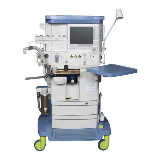
System Components Overview This chapter identifies the major physical components of the Apollo anesthesia machine and provides a brief description of specific parts. Machine Front view Lighting control (dimmer) location Central brake Screen with user interface Footrest Rotary knob Drawers (2) (for storage) -
Page 30: Machine Rear View
Use the lamp specified in the list of Type plate accessories only. Scavenging nozzle Connectors (3) for backup gas cylinder pressure Cylinder support bar sensors (covered; access from behind gas supply block) Interface panel Instructions for Use Apollo SW 4.5n... -
Page 31: Gas Supply Block
O cylinder Connection for Air cylinder Connection for O cylinder Connection for pipeline O Connection for pipeline Air Connection for pipeline N 1) This connection is not available with the "Operation without nitrous oxide" option. Instructions for Use Apollo SW 4.5n... -
Page 32: Interface Panel
System Components Interface panel IV System Connection for Dräger IV System COM2 MEDIBUS/ MEDIBUS.X interface COM1 MEDIBUS/ MEDIBUS.X interface Socket for SpO sensor (optional) 1) not for sale in the U.S. Instructions for Use Apollo SW 4.5n... -
Page 33: Vaporizers (Optional)
Always double-check the position of the vaporizer, make sure it is correctly mounted and do not mount the vaporizer park holder close to the operable vaporizer. Instructions for Use Apollo SW 4.5n... -
Page 34: Vaporizer Exclusion Systems
Vaporizer exclusion systems The exclusion systems available for the Apollo are described below. Dräger Vapor Interlock 2 System Figure 2. Dräger Vapor Interlock 2 System (Optional) The Dräger Interlock 2 system is used to ensure that... -
Page 35: Dräger Auto Exclusion 2-Vaporizer Mount (Optional)
Note: The Desflurane vaporizer should be installed in the far left position (1 in Figure 3) with the Dräger Auto Exclusion 3-Vaporizer Mount in order to have optimum viewing area of the display screen. Instructions for Use Apollo SW 4.5n... -
Page 36: Apl Valve
Route all cables away from the APL valve; do not hang lines, hoses or cables, e.g. the sample line, on or near the APL valve. Instructions for Use Apollo SW 4.5n... -
Page 37: O2 Flush
5). When actuated, the valve delivers an unmetered flow of at least 35 L/min to the breathing system and breathing bag while bypassing the ventilator. The Apollo does not have to be switched on to use the O flush. 1. To operate the O flush, press the O + button. - Page 38 When finishing oxygen therapy, make sure the flow tube is completely closed: 1. Turn the flow knob (1 in Figure 6) clockwise until it is completely closed to cut off the oxygen flow. Instructions for Use Apollo SW 4.5n...
-
Page 39: Writing Table
System Components Writing table The Apollo is equipped with a writing table Figure 7. Writing Table (1 in Figure 7) which can be moved left or right or folded down completely for convenient positioning. To fold down the writing table, support the table with... - Page 40 System Components This page intentionally left blank. Instructions for Use Apollo SW 4.5n...
-
Page 41: User Interface
Menu structure overview ..............51 Instructions for Use Apollo SW 4.5n... - Page 42 User Interface This page intentionally left blank. Instructions for Use Apollo SW 4.5n...
-
Page 43: Overview
User Interface Overview This chapter provides a description of the Apollo user interface, which enables you to view and change monitoring, ventilation, and status information using keys and the rotary knob. Main screen display The screen display is organized into four functional areas: –... - Page 44 Monitoring/configuration buttons Standard function keys; for selecting monitoring screens and silencing alarms Prompt field; displays messages for the user Ventilation parameter buttons Ventilation mode keys User-configurable monitoring area Fresh-gas bar graphs (virtual flow tubes) Instructions for Use Apollo SW 4.5n...
-
Page 45: User Controls
– press the rotary knob to set a value or confirm a selection. If the selection is not confirmed, the value or parameter will not change. Vol. AF Mode Instructions for Use Apollo SW 4.5n... -
Page 46: Standby Key
The oxygen flow control is also touch-coded with a fluted knob. – to increase flow, turn the appropriate flow control knob counterclockwise – to decrease flow, turn the appropriate flow control knob clockwise Vol. AF Mode Instructions for Use Apollo SW 4.5n... -
Page 47: Ventilation Control Keys
2. Turn the rotary knob until the desired value is displayed. 3. Press the rotary knob to confirm the new value. If the new value is not confirmed within 15 seconds, it automatically reverts to the original value. Instructions for Use Apollo SW 4.5n... -
Page 48: Monitoring/Configuration Control Keys
5. Press the rotary knob to confirm the new alarm limit value. 6. Exit the alarm limits menu by either: – confirming the close symbol > < with the rotary knob, or – pressing the > < key. Vol. AF Mode Instructions for Use Apollo SW 4.5n... -
Page 49: Led Indicators
Gray type Ventilation Buttons The ventilation buttons appear dark green when operable and turn yellow when selected. Once the value is changed and confirmed, the button turns back to dark green. Instructions for Use Apollo SW 4.5n... - Page 50 When the user selects a menu the parameters and values will appear on a dark green background. Currently selected submenus are framed in an orange border. Parameters in gray type are inactive and cannot be selected. Instructions for Use Apollo SW 4.5n...
-
Page 51: Menu Structure Overview
Check List Absorb. changed Undo Change Start Self Test Accept Cancel Test Cancel Test Standby Alarm Limits Self Test Results Absorb. changed Leak Test Datalog Page 1 Page 2 Delete Trend Cancel delete Delete Instructions for Use Apollo SW 4.5n... - Page 52 (optional) Date/Time Language Parameters Scaling Units Gas Monitoring Optional Parameters Interfaces Datalog Datalog entries triggered by COM PORT 1 MEDIBUS COM PORT 2 MEDIBUS Select MEDIBUS Screen Layout Layout 1 Layout 2 Layout 3 Instructions for Use Apollo SW 4.5n...
- Page 53 Ventilator and gas supply Parameter Default Values Gas supply checks Ventilator Default Settings Weight related settings Body Weight Related Ventilator Settings System Info General Information Activate Option Trace 1 Trace 2 Trace 3 Remote Service Monitor Mode Instructions for Use Apollo SW 4.5n...
- Page 54 (optional, only with breathing sound module) Pulse Volume (optional) Alarms On/Off 1) Only available in modes Volume, Volume AF, Pressure, Press. Support 2) Only available in modes Man/Spont., Aux CGO 3) Only available when Bypass mode is active Instructions for Use Apollo SW 4.5n...
- Page 55 User Interface Param Settings Scaling Units Agent Monitoring Datalog Entries Datalog entries triggered by System Info General Info Trace 1 Trace 2 Trace 3 Exit Config Start Timer Instructions for Use Apollo SW 4.5n...
- Page 56 User Interface This page intentionally left blank. Instructions for Use Apollo SW 4.5n...
-
Page 57: System Setup
Information about transport within the clinic ..........86 Instructions for Use Apollo SW 4.5n... - Page 58 System Setup This page intentionally left blank. Instructions for Use Apollo SW 4.5n...
-
Page 59: Overview
System Setup Overview This chapter provides information on how to set up and install all system components needed to prepare the Apollo for use. The setup procedure shall be followed by the performance of the periodic manufacturer’s procedure. WARNING! Risk of patient injury... - Page 60 The green LED labeled > AC Power< lights up (1 in Figure 16). 2. Leave the Apollo connected to the mains for 10 hours. The anesthesia machine does not have to be switched on. CAUTION! Risk of device failure In the event of a power failure, any devices connected to auxiliary power outlets will not be powered by the UPS.
-
Page 61: Installing The Breathing System And Flow Sensors
Note: Flow sensors must be recalibrated after replacement by performing the power-on self test (see chapter “Pre-use Checkout”). Instructions for Use Apollo SW 4.5n... - Page 62 If objects such as packing foil get into the device, e.g., the breathing system or the ventilator drawer, the scavenger may become blocked. Make sure that there is no packing material left inside the device. Instructions for Use Apollo SW 4.5n...
-
Page 63: Filling And Installing The Absorber
It is recommended that Drägersorb 800 + or Drägersorb FREE are used. Do not use powdered soda lime, as a higher dust load may impair functionality of the Apollo anesthesia machine. 3. Fit the canister into position below the breathing... -
Page 64: Disposable Clic Absorber (Optional)
DrägerService. WARNING! The disposable absorber must be clicked into place before switching on the Apollo. This ensures that the absorber is included in the leak and compliance test for the anesthesia machine. To click the absorber into place: 1. -
Page 65: Connecting The Gas Supply
Compressed gas supply (pipeline or cylinder): To avoid damaging the device(s) attached to a gas supply, use only medical gases. Pay particular attention to national and international standards regulating the use of medical gases. Instructions for Use Apollo SW 4.5n... -
Page 66: Connecting Pipeline Supply Of N2O, Air, And O2
LEDs on the front machine panel (1 in Figure 22) are illuminated green. 1) With the "Operation without nitrous oxide" option, connection of an N O gas supply is not possible. Instructions for Use Apollo SW 4.5n... - Page 67 If the pipeline supply pressure LEDs remain Figure 22. Location of pipeline supply pressure LEDs dark, it means that the pressure is below 39 psi or that the hoses are not connected properly. Vol. AF Mode Instructions for Use Apollo SW 4.5n...
-
Page 68: Connecting The Backup Gas Cylinders
The Apollo is equipped with ANSI standard pin- indexed hanger yokes for E-size cylinders to connect backup gas cylinders to the anesthesia machine. The... - Page 69 LEDs on the front machine panel (1 in Figure 26) are illuminated green. 1) With the "Operation without nitrous oxide" option, connection of an N2O backup gas cylinder is not possible. Instructions for Use Apollo SW 4.5n...
-
Page 70: Caution When Handling O 2 Cylinders
Do not oil or grease the O cylinder valves or O pressure reducing adapters, and do not handle with oily or greasy fingers. Note: Follow the Instructions for Use included with the pressure regulator. Instructions for Use Apollo SW 4.5n... -
Page 71: Connecting The Scavenger System
According to the particular requirements for anesthesia workstations, the use of an anesthetic gas scavenging system is required. The Apollo can be equipped with one of two kinds of scavenger systems to provide the best match with the hospital’s waste-gas disposal system. These scavenger systems must comply with ISO 8835-3. - Page 72 Always make sure the side openings of the receiving system are not blocked. Note the Instructions for Use of the anesthetic gas receiving system AGS. Instructions for Use Apollo SW 4.5n...
-
Page 73: Connecting The Passive Scavenger System (Optional)
5. Connect the other end of the hose to the hospital waste-gas disposal system. 6. Make sure that the passive scavenger system is ready for operation. For detailed information on the passive scavenger system, refer to separate Instructions for Use. Instructions for Use Apollo SW 4.5n... -
Page 74: Connecting The Endotracheal Aspiration System (Optional)
Figure 29. Endotracheal aspiration system Bracket The optional endotracheal aspiration system for the and Regulator Apollo consists of a suction regulator and a bracket that attaches to the side of the anesthesia machine. The bracket is used to hold the regulator and a suction bottle assembly of the customer’s choice. -
Page 75: Installing The Flexible Arm For The Breathing Bag
Risk of patient injury If incompatible materials are used in the patient circuit, metabolic products may build up. Breathing bags used on the Apollo must comply with current ANSI standards. Figure 30. Breathing Bag Arm Connection 1. Slide the bag arm assembly onto the breathing... -
Page 76: Connecting The Patient System
Make sure that all patient system components are tightly connected. Note: Apollo (without accessories) is not made with natural rubber latex. To minimize the risk of exposure to latex, use latex-free breathing bags and breathing hoses. Note: Only use original sample line - other lines may change the technical data for the device. -
Page 77: Connecting The Patient Circuit
Luer Lock on the Y-piece (3 in Figure 31). Ensure that all Luer fittings are securely connected. 8. Make sure that the sample line is guided correctly by using the sample line clip. This clip Instructions for Use Apollo SW 4.5n... - Page 78 APL valve. CAUTION! Risk of contamination of the device Do not put the device into operation without a water trap. Instructions for Use Apollo SW 4.5n...
- Page 79 Risk of incorrect measured values Aerosols can damage the diaphragm and the measurement system. Do not use aerosols in the breathing system. The water trap must not be used in combination with a medical nebulizer. Instructions for Use Apollo SW 4.5n...
- Page 80 For measurement purposes, a permanent sidestream flow runs through the sample line to the patient-gas measurement module. In case of a 1) Note the resistance of the breathing system and connected accessories. Instructions for Use Apollo SW 4.5n...
- Page 81 – Perform a leakage and compliance test after replacing breathing hoses, particularly extendable hoses, vaporizers, and soda lime. – Perform a leakage and compliance test after adjusting the length of extendable hoses. Instructions for Use Apollo SW 4.5n...
- Page 82 1) If necessary, take into consideration additional parts such as water traps or additional hoses. Instructions for Use Apollo SW 4.5n...
- Page 83 (60 L/min), for children (30 L/min), or for neonates (5 L/min). Instructions for Use Apollo SW 4.5n...
-
Page 84: Connecting Ac Power
Connecting AC power Connecting auxiliary devices Figure 33. Location of Auxiliary Outlets on Back of Machine The Apollo has two auxiliary outlets on the back of the machine (1 in Figure 33). Each outlet is rated 4 amps and is protected by circuit breakers. -
Page 85: Fuses For Auxiliary Outlets
Potential equalization does not replace the protective ground connection. During operation, the potential equalization connectors must be readily accessible and the connection must be able to be disconnected without the use of tools. Instructions for Use Apollo SW 4.5n... -
Page 86: Information About Transport Within The Clinic
The mains voltage must correspond to that specified Figure 35. Location of AC Power LED on the rating plate on the back of the machine. 1. Plug the mains power plug of the Apollo anesthesia machine into the mains outlet. The Vol. AF Mode green LED labeled >... - Page 87 – the ventilator module, – doors, – the writing tray, – swivel arms for mounted devices, – gas cylinders, – vaporizer units, – CLIC absorbers and CLIC adapters, as well as other accessories. Instructions for Use Apollo SW 4.5n...
- Page 88 System Setup This page intentionally left blank. Instructions for Use Apollo SW 4.5n...
-
Page 89: Pre-Use Checkout
Emergency start ............... . 107 Instructions for Use Apollo SW 4.5n... - Page 90 Pre-use Checkout This page intentionally left blank. Instructions for Use Apollo SW 4.5n...
-
Page 91: Overview
Pre-use Checkout Overview The pre-use checkout procedure must be performed to ensure that the Apollo is ready for use. This is a recommended procedure. Follow the institution’s policies for specific procedures. If the Apollo fails any checkout routine, do not use the machine until corrective action is taken. - Page 92 Do not use “cheater plugs”. The term “cheater plug” implies any and all electrical plugs or other devices that can inhibit or prohibit the proper grounding of the anesthesia machine. Instructions for Use Apollo SW 4.5n...
-
Page 93: Power On
If all LEDs do not light up upon initialization, contact DrägerService. The initial screen appears after about 20 seconds. Apollo now loads its software and tests its internal memory. Check list After about 35 seconds, a check list for manual tests... - Page 94 The external oxygen supply and the O cylinder cannot both be configured as not present at the same time. Open the backup gas cylinders which have been configured as present for the self test and then close them. Instructions for Use Apollo SW 4.5n...
- Page 95 ISO 21647 or ISO 80601-2-55 must be used. Note: The self test does not check for internal vaporizer leakage; after filling or changing vaporizers, perform the Standby leak test on each vaporizer (see page 118). Instructions for Use Apollo SW 4.5n...
- Page 96 For three-vaporizer mounts, perform this test for all three vaporizers. Note: The self test does not check for internal vaporizer leakage; after filling or changing vaporizers, perform the Standby leak test on each vaporizer (see page 118). Instructions for Use Apollo SW 4.5n...
- Page 97 If condensation is a frequent problem, install water traps in the breathing hoses. WARNING! Risk of strangulation If not positioned with care, hoses, cables, and similar machine components may endanger the patient. Take special care when connecting the patient. Instructions for Use Apollo SW 4.5n...
- Page 98 Check if the flow indicator at the AGS floats between the two marks. 4. On the AGS, make sure that the float is in between the two marks in the sight glass on the AGS. Instructions for Use Apollo SW 4.5n...
- Page 99 O flow has also stopped. 5. Close the N O flow control valve. Prepare the Apollo for the self test as follows: Figure 42. Preparing for the Self Test 1. Ensure that all flow controls are closed. 2. Occlude the Y-piece by inserting it onto the...
-
Page 100: Self Test
(1 in Figure 43) to begin the Apollo automated self test. Figure 44. Self Test Screen The automatic self test lasts approximately 3 minutes. The bar graph at the top of the Self Test... - Page 101 Risk of inadequate monitoring If the flow sensor, oxygen sensor, or gas sensor is not operational, adequate substitute monitoring must be ensured before starting the anesthesia machine! Special attention is required if operation is initiated. Instructions for Use Apollo SW 4.5n...
-
Page 102: Self Test Results
FUNCTIONAL Every component of the system is in satis- factory operational order. Yellow CONDITIONALLY FUNCTIONAL A non-critical fault was detected. Apollo may be used, but call DrägerService or your local authorized service organization. Empty The self test was canceled. Dräger recommends that a full self test is carried out before the start of therapy, after restarting the device, and at least once every 24 hours. -
Page 103: System Compliance
PEEP and plateau pressure in accordance with the determined compliance value. Leak tests The Apollo tests for leaks in the mechanical subsystem and in the Man/Spont system. Leak system Figure 48. Mechanical Ventilation Leak Test –... -
Page 104: Leak Man/Spont
150 mL/min (Leak (Man/Spont) result in Figure 47). The Apollo determines the current leakage of the breathing system and breathing hoses. The system tolerates leaks of up to 150 mL/min. Note:... -
Page 105: Locating And Eliminating Leaks
15 mm (0.59 in) circuit plug for connecting the Y-piece scratched or damaged. – Vaporizer fill or drain connections leaky or opened, vaporizer not mounted correctly, O-ring missing or handwheel not set to >0<. Instructions for Use Apollo SW 4.5n... -
Page 106: Additional Suggestions To Isolate Components Of The Breathing System For Leaks
1. Remove the vaporizers from the anesthesia machine. 2. Perform leak test. Note: The self test does not check for internal vaporizer leakage; after filling or changing vaporizers, perform the Standby leak test on each vaporizer (see page 118). Instructions for Use Apollo SW 4.5n... -
Page 107: Emergency Start
“Specifications” cannot be guaranteed. Figure 50. Apollo Front Panel The emergency start procedure shortens the self test when the Apollo must be operational immediately. Note: To prevent abuse of this feature, the emergency start procedure can be performed up to ten times in succession. - Page 108 Pre-use Checkout Apollo is ready for operation about 1 minute after initiating. The O sensor is completely calibrated after about 5 minutes. WARNING! Risk of device failure and/or patient injury Canceling the self test may lead to malfunctions; greater attention is required during operation.
-
Page 109: Operation Summary
When Apollo is not in use ........ - Page 110 Operation Summary This page intentionally left blank. Instructions for Use Apollo SW 4.5n...
-
Page 111: Overview
Do not touch the patient and the electrical device contacts at the same time. Typical operation Operation of the Apollo begins with the standby screen which is displayed after the initial self tests. This screen allows the user to restore default settings and enter the patient parameters needed to begin a case. -
Page 112: Entering The Patient's Ideal Body Weight (Optional)
Volume AF, Pressure, and Press. Support has no influence on current ventilation settings. Adjustment ranges and factory settings Parameter Adjustment Factory setting range <1 - 120 years Weight 1 lb to 240 lbs. (1 kg to 120 kg) Instructions for Use Apollo SW 4.5n... -
Page 113: Setting The Fresh-Gas Flow
100% Air can be metered throughout the entire flow range. Fresh-gas Failure Detection During operation, the Apollo checks that the piston cylinder unit has a sufficient level of fresh gas. If a sufficient level of fresh gas is not possible, the system first displays the message "FGAS LOW OR... -
Page 114: Setting Vaporizer Concentration
>0< (2 in Figure 54.) Wait 5 seconds for the pressure to balance. 3. Press the button and turn the handwheel counterclockwise to set the required anesthetic gas concentration (3 in Figure 54.). Instructions for Use Apollo SW 4.5n... -
Page 115: Changing Patients
WARNING! Risk of patient injury Restored default settings may contain settings inappropriate for a new patient. After default settings have been restored, make sure the ventilation monitoring settings are appropriate to the patient connected. Instructions for Use Apollo SW 4.5n... -
Page 116: Changing Soda Lime
(“Self test results” on page 102). A reusable absorber or the disposable CLIC absorber can be used with the Apollo. The soda lime must be exchanged, if: – the soda lime in the absorber has turned violet. The color indicator can regenerate slowly and the soda lime may revert to white, but its absorption capacity is nevertheless spent. -
Page 117: Disposable Clic Absorber (Optional)
4. Push the absorber into the machine until it engages. WARNING! Risk of increased inspiratory CO concentrations When the absorber is swung out, no CO absorbed. Always make sure the absorber is clicked into place after installing or replacing. Instructions for Use Apollo SW 4.5n... -
Page 118: Leak Test
0.2 Vol.%. Press rotary knob to start the leak test. 3. Perform the actions as instructed. Apollo performs the leak test for Volume Mode/ Pressure Mode in about 90 seconds, then system compliance is determined for volume correction and the overall system is checked for leaks in the breathing system. -
Page 119: Activating The Co2 Bypass Function (Optional)
Leakage is tested in the automatic (mechanical) ventilation line (leak (system)) and in the overall system (leak (Man/Spont)). The clock symbol disappears when the test is Figure 57. Leak test Results Screen complete and Apollo displays the following test results: – Breathing system Breathing System –... -
Page 120: End Of Operation
The workstation is now in Standby. The fresh-gas flow should be turned off. To turn the Apollo off completely (from Standby): Figure 60. Apollo Shut Down Screen 1. Press the main power switch on the front of the machine. - Page 121 The self test checks sensitive internal device processes the functionality of which, if not regularly tested, may fail or not be available. It is strongly recommend that the Apollo be switched off once a day in order to carry out the power-on self test.
-
Page 122: When Apollo Is Not In Use
Allowing the battery to run low can damage it. It must be charged at least every four weeks. Observe the following if the Apollo is not used for an extended period of time: 1. Unplug the gas pipeline hoses from the wall pipeline supply. -
Page 123: Ventilation
Changing between ventilation modes ............146 Instructions for Use Apollo SW 4.5n... - Page 124 Ending the auxiliary CGO ventilation ............151 Instructions for Use Apollo SW 4.5n...
-
Page 125: Overview
Ventilation Overview The Apollo supports the following ventilation modes: – Manual/Spontaneous ventilation Man/Spont – Volume-controlled ventilation Volume Mode. With activation of: – Sync. (Synchronization) – Press. Support (Pressure Support) (optional) – Pressure-controlled ventilation Pressure Mode. With activation of: – Sync. (Synchronization) –... -
Page 126: Manual/Spontaneous Ventilation
1. Turn the APL valve counterclockwise as far as it will go. The two points (1 in Figure 61) are vertically aligned. The valve head is raised. The pressure limitation is canceled, the valve is open for free spontaneous breathing. Instructions for Use Apollo SW 4.5n... -
Page 127: Starting Manual/Spontaneous Ventilation
1) Site defaults can be set instead. during ventilation: 2) Optional – Press the button for the parameter to be changed, turn the rotary knob to the desired value, and press the rotary knob to confirm. Instructions for Use Apollo SW 4.5n... -
Page 128: O 2 Flush
O while bypassing the vaporizer. Press the >O +< button (1 in Figure 63). O flows into the breathing system without anesthetic gas as long as the button is pressed. Instructions for Use Apollo SW 4.5n... -
Page 129: Volume-Controlled Ventilation
Ventilation Volume-Controlled Ventilation The Apollo has a volume-controlled ventilation mode Figure 64. Respiratory Cycle - Volume Mode with fixed mandatory tidal volume (V ) and frequency Pressure Trigger indicator Trigger indicator (Freq.). Synchronization can be activated, as well as PEAK... -
Page 130: Starting The Volume-Controlled Ventilation Mode
(I:E) remains constant. Only applies if trigger = OFF. See the chapter “Configuration”. The resultant ratio of inspiration to expiration (I : E) is also displayed in parallel. Optional. Instructions for Use Apollo SW 4.5n... -
Page 131: Synchronized Volume-Controlled Ventilation
50 % of the set respiratory volume will always be applied to ensure adequate volume ventilation. 4. Press the button >Extra Settings< (1 in Figure 66) again, the actual trigger sensitivity is shown above the ventilation parameter buttons. Instructions for Use Apollo SW 4.5n... -
Page 132: Synchronized Volume-Controlled Ventilation With Pressure Support (Optional)
V Pressure Support is automatically deactivated when the trigger is deactivated and set to “OFF”. The actual trigger sensitivity is shown above the keys for the ventilation parameters (2 in Figure 67). Instructions for Use Apollo SW 4.5n... -
Page 133: Volume Mode Autoflow - Volume Af (Optional)
Ventilation Volume Mode AutoFlow - Volume AF (Optional) Figure 68. Respiratory Cycle - Volume AF The Apollo has the optional ventilation mode Volume Pressure AF, a pressure-controlled ventilation mode with a guaranteed tidal volume V and frequency Freq. as well as optional synchronization activation and... -
Page 134: Starting Volume Mode Autoflow
3. Turn the rotary knob to adjust the parameter to the desired value, and press the rotary knob to Vol. AF Mode confirm (4 in Figure 69). Continue to set the values for the other parameters. Instructions for Use Apollo SW 4.5n... -
Page 135: Starting The Volume Autoflow Ventilation Mode
(I:E) remains constant. Only applies if trigger = OFF. See the chapter “Configuration”. The resultant ratio of inspiration to expiration (I : E) is also displayed in parallel. Optional. Instructions for Use Apollo SW 4.5n... -
Page 136: Synchronized Volume-Guaranteed Ventilation
(trigger indicator). 4. Press the button >Extra Settings< again. The actual trigger sensitivity is shown above the keys for the ventilation parameters. Instructions for Use Apollo SW 4.5n... -
Page 137: Synchronized Volume-Guaranteed Ventilation With Pressure Support (Optional)
The actual trigger sensitivity is shown above the keys for the ventilation parameters. (2 in Figure 71). The parameters that can be set for Pressure Mode are shown in Table 6, along with their adjustment ranges and factory settings. Instructions for Use Apollo SW 4.5n... -
Page 138: Pressure-Controlled Ventilation
Ventilation Pressure-Controlled Ventilation The Apollo has a pressure-controlled ventilation Figure 72. Respiratory Cycle - Pressure Mode mode with fixed pressure limitation P INSP Pressure Trigger indicator Trigger indicator frequency Freq. as well as with optional synchronization and variable Pressure Support for INSP spontaneous breathing efforts (optional). -
Page 139: Starting The Pressure-Controlled Ventilation Mode
The resultant ratio of inspiration to expiration (I : E) is also displayed in parallel. Depending on the configuration, the pressure limit ( can be changed INSP) automatically together with adjustment of the PEEP value. See the chapter “Configuration”. Optional. Instructions for Use Apollo SW 4.5n... -
Page 140: Synchronized Pressure-Controlled Ventilation
The active window for the stroke triggered by the patient corresponds to the last 25% of the applicable expiratory time. 4. Press the button >Extra Settings< again, the actual trigger sensitivity is shown above the ventilation parameter buttons. Instructions for Use Apollo SW 4.5n... -
Page 141: Synchronized Pressure-Controlled Ventilation With Pressure Support (Optional)
The trigger sensitivity is shown above the ventilation parameter buttons (2 in Figure 75). The parameters that can be set for Pressure Mode are shown in Table 6, along with their adjustment ranges and factory settings. Instructions for Use Apollo SW 4.5n... -
Page 142: Pressure Support Ventilation (Optional)
Ventilation Pressure Support Ventilation (Optional) The Apollo has a pressure-assisted ventilation mode Figure 76. Respiratory Cycle - Pressure Support Mode for patients with spontaneous breathing. Trigger indicator Trigger indicator Synchronization and Pressure Support for the Pressure Apnea spontaneous breathing efforts are controlled by the ventilation sensitivity of the flow trigger and by the level of ΔP... -
Page 143: Starting Pressure Support Ventilation
[kg/lbs.] Site defaults can be set instead. The inspiratory time is limited by adjustment of Freq. to yield a maximum ratio of 1:1 for (I : E), thus ensuring an adequate expiratory time. Optional Instructions for Use Apollo SW 4.5n... - Page 144 There is 15 second timeout period for making ventilation mode changes, with a 5-second audible tone sequence after the first 10 seconds. If the new setting is not confirmed within the timeout period, the current ventilation setting remains in effect. Instructions for Use Apollo SW 4.5n...
-
Page 145: Continuous Positive Airway Pressure Cpap - In Pressure Support Mode (Optional)
Ventilation Continuous Positive Airway Pres- sure CPAP - in Pressure Support Mode (Optional) The pressure support option on the Apollo is enhanced with Continuous Positive Airway Pressure (CPAP). CPAP allows the patient to breath spontaneously on an increased pressure level and therefore helps to increase the functional residual capacity. -
Page 146: Changing Between Ventilation Modes
Note: In minimum flow mode, the following secondary effects may occur that affect ventilation of the patient: – Leakage: Check if the breathing bag is adequately filled. Instructions for Use Apollo SW 4.5n... -
Page 147: Automatic Parameter Changes
1. Press the >Freq< button on the Volume or Pressure Mode screen. The key lights up yellow, along with the value for T , to indicate that INSP both values will change (1 in Figure 78). Instructions for Use Apollo SW 4.5n... -
Page 148: Auxiliary Common Gas Outlet (Aux Cgo) Ventilation (Optional)
Only use devices with a breathing bag and/ or pressure relief valve. – Check the fresh-gas flow and the condition of the breathing bag. – Do not use the non-rebreathing system if the flow is insufficient. Instructions for Use Apollo SW 4.5n... -
Page 149: Diverting Fresh Gas To The Auxiliary Cgo
, CO , and anesthetic gases: 2. Connect the sample line to the Luer lock connection on the mask manifold and to the water trap connection on the front of the Apollo (1 in Figure 80). For mask manifolds without a sample line connector: –... -
Page 150: Starting The Auxiliary Cgo Monitoring
, and P are measured at the PEAK MEAN auxiliary common gas outlet. Pressure measurement may be impaired by activating the O flush. The minute volume MV and tidal volume V are not measured. Instructions for Use Apollo SW 4.5n... -
Page 151: Ending The Auxiliary Cgo Ventilation
Excess fresh gas can be discharged into the anesthetic gas scavenging line via the breathing system of the Apollo. For this purpose, the non- rebreathing system must be connected to the Y-piece of the breathing hoses connected to the breathing system. - Page 152 Ventilation This page intentionally left blank. Instructions for Use Apollo SW 4.5n...
-
Page 153: Monitoring
Screen timer ................173 Instructions for Use Apollo SW 4.5n... - Page 154 Connecting the SpO2 sensor to the Apollo ........
-
Page 155: Overview
Monitoring Overview The Apollo has three basic screens for the display of monitoring information: standard, data, and trend. The gas measurement and gas delivery windows remain displayed in all three screens, but the information presented in the graphical/numerical window will change, depending on the selected screen and user configuration. -
Page 156: Screen Layout
3. Turn the rotary knob to select an option, and press the rotary knob to confirm. The option becomes highlighted in yellow. Instructions for Use Apollo SW 4.5n... -
Page 157: Displayed Parameters
The specific parameters that are displayed will vary, depending on the selected screen and user configuration. concentration – Curve display – Numerical display: – etCO (end-tidal CO concentration) – FiCO (fractional inspiratory CO concentration) – Trend curve for CO Instructions for Use Apollo SW 4.5n... -
Page 158: O2 Concentration
– VT (measured inspiratory tidal volume) INSP – ΔV difference between inspiratory and expiratory tidal volume) – Freq. (respiratory rate) – MV (difference between the inspiratory LEAK and expiratory minute volume) (only on data screen) Instructions for Use Apollo SW 4.5n... -
Page 159: Spo2 Concentration (Optional)
– ♥ (pulse rate) – Trend curve for SpO and pulse Loops (Optional) Graphical display for the following measured and calculated values: – Pressure/Volume – Flow/Volume “Loops (Optional)” on page 168 for more detailed information. Instructions for Use Apollo SW 4.5n... -
Page 160: Mini Trends (Optional)
Ventilation source module Shows the indicators for the ventilation sources (with the active source highlighted) and displays the P real-time signal. Manual ventilation (Man/Spont) Non-rebreathing system at the auxiliary common gas outlet (Aux CGO) Automatic ventilation Instructions for Use Apollo SW 4.5n... -
Page 161: Vt/Paw Module
The low flow wizard shows bar graphs for the minimum required flow (leak and uptake) and for the total fresh-gas flow. Both graphs have the same scale. Instructions for Use Apollo SW 4.5n... -
Page 162: Volumeter Module
The expiratory tidal volume is shown in numerics above the graph. Leakage is indicated by the bar remaining in the graph at the end of the expiratory phase. Instructions for Use Apollo SW 4.5n... -
Page 163: Gas Measurement
, and of the anesthetic agents N O, halothane, enflurane, isoflurane, desflurane, and sevoflurane is measured. Apollo automatically identifies the anesthetic agent used and adjusts the measurement and monitoring of the anesthetic gas concentration to suit the gas identified. When no anesthetic agent is applied, the message “No agent”... -
Page 164: Calibration
If apnea occurs, the display for etCO is replaced by the message apnea CO . The apnea time [min:sec] is displayed instead of the measured value. Instructions for Use Apollo SW 4.5n... -
Page 165: Mixture Detection
CO and O Mixture detection Apollo automatically detects the anesthetic gas used and switches the measurement and monitoring of anesthetic gas concentration to the gas detected. If there is a mixture of two volatile anesthetic agents, the concentration of the secondary anesthetic agent is displayed if the xMAC value is 0.1 MAC or greater. -
Page 166: Mac Definition
The values indicated in the table relate to an age of 40 years. Age-dependent MAC values The MAC values used in Apollo are corrected for Figure 87. Influence of Age on MAC age. Therefore make sure that the age of the patient Influence of age on the MAC value is entered correctly. -
Page 167: Xmac Display (Mac Multiple)
(MAC multiple) The MAC value is a simple navigation aid for anesthetic gas metering. Apollo indicates the MAC multiple (xMAC), which is determined from the present expiratory measurements and the age-dependent MAC values. In the gas of gas mixtures, the respective multiples... -
Page 168: Loops (Optional)
In addition to the factory setting for the axis orientation complying with ISO 80601-2-13, inverted display is also available. To change the display setting, contact service personnel. See the chapter “Configuration” for more information on scale configuration. Instructions for Use Apollo SW 4.5n... - Page 169 Standby mode. To remove loops from the screen: 1. Press the >Exit Loops< button while in the loops screen (2 in Figure 90). The loops are removed and the two lower curves are displayed again. Instructions for Use Apollo SW 4.5n...
-
Page 170: Mini Trends (Optional)
The parameter MV*CO indicates the CO volume that is expired by the patient. The scaling depends on the expiratory tidal volume and is automatically adjusted. MV*CO2 1000 1000 Instructions for Use Apollo SW 4.5n... -
Page 171: Mini Trend For O2 Uptake
PEEP is displayed as a line, patient compliance C as filled curve. The scaling for PEEP is set to 20 mbar. The scaling for C depends on the expiratory tidal volume V and is automatically adjusted. 1000 Instructions for Use Apollo SW 4.5n... -
Page 172: Datalog
Datalog and trend memory are deleted simultaneously! The Datalog will be maintained even after switching off the Apollo completely. It can only be deleted by using the “Delete Trend” functionality in Standby. Refer to “Deleting the trend memory” on page 176. -
Page 173: Screen Timer
The measured time is displayed on the key. To reset the timer: – Press the >Reset timer< button Figure 99. Reset Timer Soft Key (1 in Figure 99). The time is reset and the key label changes back to >Start timer<. Instructions for Use Apollo SW 4.5n... -
Page 174: Data Screen
The modules displayed below and the numerical values are the same as those configured for the standard screen (see “Screen layout” on page 156). Instructions for Use Apollo SW 4.5n... -
Page 175: Trend Screen
It becomes available after 30 minutes of trend data is collected. The zoom window appears as a rectangle on the trend. The rectangle can be moved by the user to select the area to magnify. Instructions for Use Apollo SW 4.5n... -
Page 176: Deleting The Trend Memory
3. Press the >Delete< button to delete all trend and Datalog data (1 in Figure 105). Figure 105. Confirm Cancel Screen in Standby Press the >Cancel Delete< button to cancel the deletion (2 in Figure 105). Instructions for Use Apollo SW 4.5n... -
Page 177: Monitoring Mode
Exit monitoring mode and begin ventila- tion 1. Press any of the ventilation keys at bottom of the display panel (3 in Figure 107), and confirm by pressing the rotary knob (2 in Figure 107). Vol. AF Mode Instructions for Use Apollo SW 4.5n... -
Page 178: Spo2 Measurement (Optional)
Selecting a sensor Only OxiMax sensors or Durasensors from Nellcor must be used (see separate list of accessories). The OxiMax modules implemented in the Apollo are only compatible with the OxiMax sensors (purple probe or white probe for MAX FAST). -
Page 179: Connecting The Spo2 Sensor To The Apollo
Connecting the SpO sensor to the Apollo At the back of the machine: Figure 109. Location of SpO Sensor Connection 1. Plug the sensor connector into the socket marked >SpO < (see Figure 109). sensor socket Instructions for Use Apollo SW 4.5n... -
Page 180: Safety-Relevant Information
CAUTION! Risk of patient injury Risk of failure or inaccurate data The Apollo anesthesia machine has been verified to If positioned close to a bright light source, the pulse function with Nellcor pulse oximeter probes. The signal may fail or the results may be inaccurate. -
Page 181: Applying The Durasensor Ds-100 A
The lead should be on top of the finger. 2. Make sure that the finger is not compressed or hurt by the clip. Instructions for Use Apollo SW 4.5n... -
Page 182: Test Considerations And Oximeter Accuracy
CAUTION! Risk of inaccurate data If simulators are used as calibrators, the SpO module may produce incorrect data. Simulators must not be used as calibrators. Instructions for Use Apollo SW 4.5n... -
Page 183: Alarms
Auto-Set of alarm limits ..............197 Instructions for Use Apollo SW 4.5n... - Page 184 Alarms This page intentionally left blank. Instructions for Use Apollo SW 4.5n...
-
Page 185: Alarm Priorities And Alarm Signals
Alarm messages are color-coded and assigned to three priority classes by the Apollo, depending on their urgency: Warning –... -
Page 186: Downgrading Alarm Priorities
Figure 111) and will flash. The color of the background reflects the color-coding of the alarm priority (red, yellow, cyan). For a complete list of Apollo alarm messages, see “Alarm - Cause - Remedy” on page 267. Downgrading alarm priorities... -
Page 187: Alarm Displays
The upper curve display reappears when the button >Show All Alarms< is pressed again or when the 15 seconds have expired. Instructions for Use Apollo SW 4.5n... -
Page 188: Suppressing Alarms
Audio and visual alarms can be disabled by adjusting the default alarm limits in the standby configuration screen. Certain alarms can also be disabled automatically, based on ventilation mode. See the chapter “Configuration” for complete information. Instructions for Use Apollo SW 4.5n... -
Page 189: Alarm Behaviour When Changing Ventilation Modes
SpO , the symbol disappears. Alarm behaviour when changing ventila- tion modes The Apollo has an automatic suppression of active MV low and apnea alarms implemented, when changing ventilation modes. This suppression applies when the user changes from a ventilation mode with a low mandatory... -
Page 190: Limit-Based Alarms Activated In Respective Ventilation Modes
Alarms Limit-based alarms activated in respective ventilation modes When a ventilation mode is changed, the Apollo sets the alarms ON or OFF as indicated in the table below. Some alarms can be then be enabled or disabled manually by the user. -
Page 191: Enabling/Disabling Alarms Globally During Operation
1. Press the >CO Alrm ONoff< key (1 in Figure 116). The symbol > < appears beside the measured values for end-expiratory and inspiratory CO concentration. The button label changes to >CO Alrm OFFon<. Instructions for Use Apollo SW 4.5n... - Page 192 National standards require a minimum monitoring with some alarm functions. These standards may not be met if the alarm function of the etCO monitoring parameter is disabled. Only disable this monitoring parameter after consulting national standards. Instructions for Use Apollo SW 4.5n...
-
Page 193: Enabling/Disabling Spo2 Alarms (Optional)
National standards require a minimum monitoring with some alarm functions. These standards may not be met if the alarm function of the SpO monitoring parameter is disabled. Only disable this monitoring parameter after consulting national standards. Instructions for Use Apollo SW 4.5n... -
Page 194: Bypass Mode
(optional) is only reactivated when pulse signals have been detected again. Deactivating the bypass mode has no effect on the “On” or “Off” status of SpO measurement; the last status set is retained. Instructions for Use Apollo SW 4.5n... -
Page 195: Displaying And Setting Alarm Limits
Figure 120). The menu lists the parameters, their current measured values, and the current low and high alarm limits. The alarm limits also appear on the curves as dashed lines (3 in Figure 120). Instructions for Use Apollo SW 4.5n... -
Page 196: To Set An Alarm Limit
0 to 19.9; -- > 19 to 99; -- < [Vol.%] 18 to 98 > inHal. 0.1 to 8.4 < [Vol.%] 0 to 8.3; -- > inIso. 0.1 to 8.4 < [Vol.%] 0 to 8.3; -- Instructions for Use Apollo SW 4.5n... -
Page 197: Auto-Set Of Alarm Limits
1. Press the rotary knob or the > < key. The new alarm limits for MV are calculated by the Apollo from the measured value for the minute volume MV in Volume Mode, Volume AF, Pressure Mode, and Pressure Support (optional) as shown... - Page 198 The new alarm limits for P are calculated by the Apollo on the basis of the mean values for PEAK, PLAT, and PEEP over the last four machine strokes. Spontaneous breaths by the patient and triggered Pressure Support strokes are not taken into account.
-
Page 199: Configuration
Configuration during operation ............220 Instructions for Use Apollo SW 4.5n... - Page 200 Setting the patient’s age and weight during operation ..........224 Instructions for Use Apollo SW 4.5n...
-
Page 201: Overview
Configuration Overview The user can configure settings on the Apollo in Standby mode as well as during operation. Standby configuration allows the user to save a complete set of defaults that are invoked automatically when the machine is switched on (see “Configuring the default... -
Page 202: System Settings
Settings standby configuration screen: Alarm volume See 1 in Figure 125. The minimum alarm volume can be set to a value between 1 to 9. The standard alarm volume cannot be set below this limit. Instructions for Use Apollo SW 4.5n... -
Page 203: Breathing Sound
Apollo takes into account the national regulations of certain countries which require a minimum volume of 45 dB (A). For these countries Apollo is shipped with factory settings in which the alarm volume cannot be set to values between 1 to 3. -
Page 204: Parameters
15, 30, 60, 120 L per minute Tidal volume: auto 50, 150, 500, 1000 mL, auto : 100 %, auto auto – The setting is made automatically or by selecting a pre-set scale. Instructions for Use Apollo SW 4.5n... -
Page 205: Units
Optional parameters See 4 in Figure 126. Parameter Factory setting : yes/no Automatic setting Option available: yes Option not available: no For a detailed description of SpO monitoring, see page 178. Instructions for Use Apollo SW 4.5n... -
Page 206: Interfaces Datalog
Datalog deletes the oldest entries. When the Apollo is switched off, all Datalog entries are saved and are available upon the next start-up of the Apollo. The device also records the time when the device was switched off. -
Page 207: Screen Layout
Three modules which may be assigned to parameters or status displays (2 in Figure 128). The available modules are displayed when a module is selected (1 in Figure 129). Each curve/module can also be configured as being blank. Instructions for Use Apollo SW 4.5n... - Page 208 Certain monitoring options are mandatory depending on the applicable national requirements. Some monitoring options may not be covered by certain screen layout configurations. Always take national standards into account when configuring the screen layout. Instructions for Use Apollo SW 4.5n...
-
Page 209: Setting Alarm Limits
Two dashes > < indicate that the corresponding alarm is disabled. Note: The new default alarm limits are effective whenever the anesthesia machine is switched on and after selecting >Restore default settings< in Standby. Instructions for Use Apollo SW 4.5n... -
Page 210: Default Agent Limits
>Yes<, the value is adopted from the automatic ventilation mode. For further information, “Troubleshooting” on page 257. Alarm Factory setting High: Yes/No MV: Yes/No Agent (I) low: Yes/No etCO : Yes/No FiCO : Yes/No apnea alarm cascade: Yes/No Instructions for Use Apollo SW 4.5n... -
Page 211: Therapy Related
(Optional)” on page 112.) MV alarms in Bypass mode? : Yes/No If >MV alarms in Bypass mode?< is set to Yes, MV alarms and flow apnea monitoring are activated in bypass mode. Instructions for Use Apollo SW 4.5n... -
Page 212: Device Related
1 to 60 days; – – Determine the operating time interval for the soda lime. As soon as the interval has expired the advisory message ABSORB. DEPLETED? will be issued. 1) The function is disabled. Instructions for Use Apollo SW 4.5n... -
Page 213: Other
(see page 222). If set to no, these alarms will be raised with normal alarm cascade behavior. 1. Press the >Exit< key to exit the Alarm Limits > Misc alarm settings menu Instructions for Use Apollo SW 4.5n... -
Page 214: Ventilator And Gas Supply
Ventilation Parameters” on page The trigger sensitivity can be set separately in the available ventilation modes. If the trigger has been pre-set to “OFF” in Volume Mode, Volume AF Mode, or Pressure Mode, the Instructions for Use Apollo SW 4.5n... -
Page 215: Gas Supply Checks
PEEP and INSP remains constant. INSP When >No< is set: Parameter value P remains unaffected by INSP changes inthe ventilation parameter PEEP. Factory setting: >Yes< Instructions for Use Apollo SW 4.5n... - Page 216 - 2. This is also true for INSP changes to P INSP In the Pressure Support Mode, PEEP + ΔP will not be exceeded. This is also true for changes to ΔP Factory setting: >No< Instructions for Use Apollo SW 4.5n...
-
Page 217: Body Weight Related Ventilator Settings
60 to 150 300 to 500 550 to 800 – Restore factory default presets Select and confirm to restore the factory default setting. The default settings are activated immediately upon exiting the configuration menu. Instructions for Use Apollo SW 4.5n... -
Page 218: System Information
(refer to Figure 135). 2. When the complete code is entered, activate, select, and confirm the menu item via the rotary knob. Trace 1, Trace 2, Trace 3 Description of internal equipment states and parameters. Instructions for Use Apollo SW 4.5n... -
Page 219: Remote Service
137). 3. Connect the Remote Service Link to the COM 1 interface. The service data of the Apollo can now be transferred. For further operation, see the Instructions for Use for the Remote Service Link. After exiting the Remote Service: 4. -
Page 220: Configuration During Operation
System Info (4 in Figure 139) A dark green button indicates which screen is currently active. Light green buttons indicate which screens are available for selection. Each configuration screen is described in the following paragraphs. Instructions for Use Apollo SW 4.5n... -
Page 221: Volumes/Alarms
The NO O SUPPLY alarm is always announced at the maximum volume. Apollo takes into account the national regulations of certain countries which require a minimum volume of 45 dB (A). Settings 1 to 3 are not available for these countries. -
Page 222: Scaling
– 1 to 2 years: 150 mL – >2 years to 10 years: 500 mL – >10 years: 1000 mL Units – : mmHg, Vol.%, kPa – : hPa, mbar, cmH – Agents: Vol.%, kPa Instructions for Use Apollo SW 4.5n... -
Page 223: Agent Monitoring
Software Versions of the individual components – Software Options – Gas Consumption and sampling rate of the patient gas module – Operating Hours of individual components Trace 1, Trace 2, Trace 3 Description of internal equipment states and parameters. Instructions for Use Apollo SW 4.5n... -
Page 224: Exit Sysinfo
In the modes Man.Spont, Aux CGO, and Monitoring, the keys are directly accessible. 1. Push the button >Age< or >Weight< (refer to Figure 145) to change and confirm with the rotary knob. Figure 145. Extra Settings Instructions for Use Apollo SW 4.5n... -
Page 225: Cleaning And Maintenance
Care list for Apollo components ........ - Page 226 Disposing of the medical device ............255 Instructions for Use Apollo SW 4.5n...
-
Page 227: Overview
Cleaning and Maintenance Overview This chapter provides complete instructions for the disassembly and cleaning of the Apollo anesthesia machine. Note: Set the Apollo to Standby before disassembly. Disassembling components Observe before disassembly Disconnecting from the mains Switch off the device and accessory devices and remove their mains plugs. -
Page 228: Removing The Water Trap
Note the Instructions for Use. 3. Disconnect the breathing bag and arm (2 in Figure 148) by loosening the two thumb screws. 4. Prepare the parts for conditioning in a cleaning and disinfection machine. Instructions for Use Apollo SW 4.5n... - Page 229 Removing the microbial filter (optional) On the sleeve of the nozzle: 1. Pull the filter off the nozzle. 2. Prepare the microbial filter for conditioning according to the corresponding Instructions for Use. Instructions for Use Apollo SW 4.5n...
-
Page 230: Removing The Absorber
1. Loosen the three sealing screws on the ventilator (3 in Figure 150) a quarter turn counterclockwise with the wrench supplied. 2. Pull the breathing system up and out by the handle (4 in Figure 150). Instructions for Use Apollo SW 4.5n... -
Page 231: Removing The Ventilator Diaphragm
Sterilizing the Spirolog flow sensors in high- temperature steam will damage them and cause the flow measurement to fail. Disinfect and clean the Spirolog flow sensor as described in the Instructions for Use of the Spirolog and SpiroLife flow sensors. Instructions for Use Apollo SW 4.5n... -
Page 232: Opening The Breathing System
3. Lift off the metal valve plate (1 in Figure 155). Figure 155. Removing the Valve Plate 4. Prepare the housing parts for conditioning in a cleaning and disinfection machine. 5. Place the metal valve plate in the cleaning and disinfection machine. Instructions for Use Apollo SW 4.5n... -
Page 233: Removing The Anesthetic Gas Receiving System Ags (Optional)
(7 in Figure 157). The particle filter can be disposed of with ordinary waste after being sealed (see “Inspection” on page 252). Note the Instructions for Use of the anesthetic gas receiving system AGS. Instructions for Use Apollo SW 4.5n... -
Page 234: Removing The Passive Scavenger System (Optional)
WARNING! Risk of infection Fluids gathered in the suction bottle may be infectious and therefore dangerous for hospital personnel. Always wear gloves when emptying the suction bottle. Instructions for Use Apollo SW 4.5n... -
Page 235: Cleaning And Disinfection Guidelines
If equipment parts are to be cleaned by hand, they must always be disinfected first for personal protection. When equipment parts are to be cleaned and disinfected by machine, they should always be cleaned first and then disinfected. Instructions for Use Apollo SW 4.5n... -
Page 236: Cleaning/Disinfection Objective And Methods
“Choice of disinfectant” on page 237) – Mechanical cleaning with high-temperature disinfection (≥199 °F (93 °C) , ≥10 min). This is the preferred method for many Apollo components; a suitable cleaning agent must be added. – Manual disinfection in a bath. Extensive personal protection is required due to inhalation of vapors. -
Page 237: Disinfecting/Cleaning/Sterilizing
The supplier/manufacturer of the cleaning agent/disinfectant should be contacted if there is any doubt as to the suitability of a product. Surfaces Surfaces of the Apollo, compressed gas hoses, and cables: – Wipe off impurities with a damp disposable cloth. -
Page 238: Breathing System And Absorber
The valve plate must be sterilized after washing in order to dry it. Wipe the heating contacts of the metal valve plate and their counterparts on the ventilator module with a cloth to remove detergent residue. Instructions for Use Apollo SW 4.5n... -
Page 239: Care List For Apollo Components
The valve plate must be sterilized after washing in order to dry it. Correct operation of the workstation may be impaired and lead to failure of the workstation if the control areas in the valve plate are not dried completely. The parts should be cleaned and disinfected by machine. If not, they must be disinfected by immersion and then cleaned. Instructions for Use Apollo SW 4.5n... -
Page 240: Reassembling Components
Risk of device failure If inappropriate substances are used for hygienic preparation, the device and its components may be damaged (corrosion, condensation). Apollo and its components must not be treated with formaldehyde vapors or ethylene oxide. Reassembling components WARNING! Risk of scavenger becoming blocked If objects such as packing foil get into the device, e.g., the breathing system or the... -
Page 241: Assembling The Breathing System
30 minutes. – Before inserting the flow sensor, check for visible damage and soiling such as residual mucus, medication aerosols, and particles. – Replace flow sensors when damaged, soiled, or not particle-free. Instructions for Use Apollo SW 4.5n... -
Page 242: Installing The Ventilator Diaphragm
Installing the breathing system 1. Carefully seat the breathing system onto the Figure 163. Installing the Breathing System ventilator module. 2. Tighten the three sealing screws (1 in Figure 163) on the ventilator cover. Instructions for Use Apollo SW 4.5n... -
Page 243: Filling And Installing The Absorber
The appropriate adapter must be installed by experts, e.g. DrägerService. Note: The disposable absorber must be clicked into place before switching on the Apollo. This ensures that the absorber is included in the leak and compliance test for the anesthesia machine. - Page 244 CO; – absorption and/or decomposition of the inhalation anesthetic. These reactions could pose a danger to the patient. If using dry gases, only briefly flush the anesthesia system and only if necessary. Instructions for Use Apollo SW 4.5n...
-
Page 245: Installing The Breathing Bag And Arm
Risk of patient injury If incompatible materials are used in the patient circuit, metabolic products may build up. Breathing bags used on the Apollo must comply with current ANSI standards. 1. Slide the bag arm assembly onto the breathing bag port on the side of the breathing system... -
Page 246: Connecting The Breathing Hoses
WARNING! Risk of patient injury If incompatible materials are used in the patient circuit, metabolic products may build up. Breathing hoses used on the Apollo must comply with current ANSI standards. WARNING! Risk of burns Conductive breathing hoses or face masks may cause burns during HF surgery. -
Page 247: Reassembling The Anesthetic Gas Receiving System Ags (Optional)
Cleaning and Maintenance should be attached to the expiratory port of the breathing system. Note: Apollo (without accessories) is not made with natural rubber latex. To minimize the risk of exposure to latex, use latex-free breathing bags and breathing hoses. -
Page 248: Connecting The Anesthetic Gas Receiving System Ags (Optional)
If the side openings of the receiving system are blocked, negative pressure may result in the breathing system and the patient’s lungs. Always make sure the side openings of the receiving system are not blocked. Instructions for Use Apollo SW 4.5n... -
Page 249: Connecting The Passive Scavenger System (Optional)
5. Connect the other end of the hose to the hospital waste-gas disposal system. 6. Make sure that the passive scavenger system is ready for operation. For detailed information on the passive scavenger system, refer to separate Instructions for Use. Instructions for Use Apollo SW 4.5n... -
Page 250: Connecting The Endotracheal Aspiration System (Optional)
The optional endotracheal aspiration system for the Figure 171. Endotracheal aspiration system Bracket and Regulator Apollo consists of a suction regulator and a bracket that attaches to the side of the anesthesia machine. The bracket is used to hold the regulator and a suction bottle assembly of the customer’s choice. -
Page 251: Maintenance
Measures intended to determine and assess the actual state of a medical device Preventive maintenance Recurrent specified measures intended to maintain the functional condition of a medical device Repair Measures intended to restore the functional condition of a medical device after a device malfunction Instructions for Use Apollo SW 4.5n... -
Page 252: Inspection
Flow sensor If required, if configuration is no Replace Users longer possible. Filter mat, patient gas module Every 12 months Replace Service personnel Instructions for Use Apollo SW 4.5n... - Page 253 Inspection and Experts service Technical customers documentation according to IEC/EN 60601 is available upon request. Repair Dräger recommends that all repairs are carried out by DrägerService and that only authentic Dräger repair parts are used. Instructions for Use Apollo SW 4.5n...
-
Page 254: Emptying Or Replacing The Water Trap
Figure 173. 3. Draw off the water, remove the filled syringe and dispose of it, refer to the Instructions for Use. 4. Push the water trap into place until it engages. Instructions for Use Apollo SW 4.5n... -
Page 255: Disposing Of The Medical Device
The device and its components must be disinfected and cleaned before disposal! At the end of its service life: – Have the medical device appropriately disposed of in accordance with applicable laws and regulations. Instructions for Use Apollo SW 4.5n... - Page 256 Do not throw batteries into fire. Do not force batteries open. The battery of this medical device contains pollutant substances. 1. Do not recharge batteries. 2. Observe the applicable laws and regulations for battery disposal. Instructions for Use Apollo SW 4.5n...
-
Page 257: Troubleshooting
Alarm - Cause - Remedy ..............267 Instructions for Use Apollo SW 4.5n... - Page 258 Troubleshooting This page intentionally left blank. Instructions for Use Apollo SW 4.5n...
-
Page 259: Overview
Troubleshooting Overview This chapter discusses several types of failure that may occur on the Apollo and provides courses of action following the failure. An alphabetical list of all Apollo alarms and their causes and remedies is provided on page 267. -
Page 260: Gas Failure
“Specifications” of the instructions for use for accuracy). Gas failure If the gas supply fails, the Apollo displays a Figure 175. NO O SUPPLY Alarm Message corresponding message in the status field at the top of the screen (1 in... - Page 261 Risk of increased ambient gas concentrations If the breathing bag is not attached, expiratory anesthetic agents can escape from the breathing system. Make sure the breathing bag is attached and ensure sufficient ambient air circulation. Instructions for Use Apollo SW 4.5n...
-
Page 262: Ventilator Failure
Set the APL valve to the correct pressure limiting value and ventilate the patient manually. WARNING! Risk of patient injury If pressure or volume monitoring fails, the patient cannot be adequately monitored. Ensure adequate substitute monitoring. Instructions for Use Apollo SW 4.5n... -
Page 263: Fresh-Gas Delivery Failure
Check vaporizer setting and set the O flow to a sufficient level. Note: Refer to the total flow meter for approximate flow (see the chapter “Specifications” of the instructions for use for accuracy). Instructions for Use Apollo SW 4.5n... -
Page 264: Ventilator And Fresh-Gas Delivery Failure
(2 in Figure 179): “Ventilator failure! Only manual ventilation possible.” The Apollo automatically switches to the Monitoring mode. 1. Check the vaporizer setting. 2. Ventilate the patient manually. WARNING! Risk of patient injury... -
Page 265: Display Failure
1. Switch the Apollo off. In both cases, to ensure alternative delivery of 100 % O and anesthetic agent: 1. Check the vaporizer setting. 2. Close all flow controls (except O ), and run 100% Instructions for Use Apollo SW 4.5n... - Page 266 Check the oxygen supply, open cylinder valves if necessary. If fresh gas is still not delivered or manual ventilation is not possible, close all flow controls. Disconnect the anesthesia machine from the patient and use an alternative method of ventilation. Instructions for Use Apollo SW 4.5n...
-
Page 267: Alarm - Cause - Remedy
Troubleshooting Alarm - Cause - Remedy Apollo divides alarm messages into three priority classes identified by different colors: Warning - message with high priority (red) Caution - message with medium priority (yellow) Advisory- message with low priority (cyan) Machine-related alarms identified by an asterisk (*) can be downgraded to a lower priority or canceled altogether by pressing the >... - Page 268 No spontaneous breathing. Patient must immediately be ventilated manually! Check patient's spontaneous breathing ability. Make sure everything is connected. Check hose system and tube. Breathing/ventilation has stopped. Patient must immediately be ventilated manually! Check ventilator setting. Instructions for Use Apollo SW 4.5n...
- Page 269 Advisory uninterruptible power supply is almost Prepare manual ventilation with exhausted. 100% O Warning BREATH. SYS. TEMP. HIGH Breathing system temperature is too high. Check breathing system and breathing (26) gas temperatures. Call DrägerService. Instructions for Use Apollo SW 4.5n...
- Page 270 CO absorber. (in Standby only) Advisory COM PORT 1 FAIL Communication via the corresponding Check the plug connection on Apollo and COM PORT 2 FAIL COM port has been interrupted. the on-line equipment. Warning CONTINUOUS PRESSURE The breathing pressure exceeds the set...
- Page 271 High respiratory rates. Adjust alarm limits if necessary. At high ventilation frequencies, the measured value cannot keep up completely with the gas concentration for reasons due to the system. Dead space ventilation. Check ventilation settings. Instructions for Use Apollo SW 4.5n...
- Page 272 31 to 180 seconds. Warning (31) = insp. gas concentration > upper alarm limit for >180 seconds. Check vaporizer and fresh-gas settings. Inspiratory anesthetic gas concentration exceeds the high alarm limit for at least two breaths. Instructions for Use Apollo SW 4.5n...
- Page 273 O concentration in the fresh- (12) the upper alarm limit of 82%. gas flow. Flush. Caution INSP. O HIGH Inspiratory O concentration exceeds the Check O concentration in the fresh-gas (12) upper alarm limit. flow. Instructions for Use Apollo SW 4.5n...
- Page 274 O backup cylinder empty or closed and Use a new N O backup cylinder or open Advisory central N O supply not available or not the cylinder valve. (25/7) connected. Use the pipeline supply. Instructions for Use Apollo SW 4.5n...
- Page 275 O backup cylinder. Advisory Check pipeline supply. (25/10) Pipeline supply hose not connected or Check connection to pipeline supply. kinked. O cylinder empty or closed. Connect a full N O cylinder or open the cylinder valve. Instructions for Use Apollo SW 4.5n...
- Page 276 Pressure Support mode for more than line. 30 seconds. Caution PINSP NOT ACHIEVED The inspiratory pressure set in Pressure Check set ventilation parameters; repair (12) Mode is not achieved. leak if applicable. Fresh-gas shortage. Check fresh-gas setting. Instructions for Use Apollo SW 4.5n...
- Page 277 Warning Measured oxygen saturation value is Check ventilation. (31) below lower alarm limit. Check application of SpO sensor. Check O concentration of fresh-gas flow. SENS. DISCONNECT. sensor not connected. Check sensor connection. Advisory (10) Instructions for Use Apollo SW 4.5n...
- Page 278 All alarms for the measured values Connect sample line. measured values concerned have been temporarily Connect SpO sensor. disabled. Connect patient. The alarm system is waiting for For more details, see page 190. automatic measurement wake-up (AutoWakeUp) Instructions for Use Apollo SW 4.5n...
- Page 279 Set alarm limits, see page 195. displayed beside measured measured value concerned has/have values been disabled. Grayed out values The set value differs from the delivered value. Grayed out measured values The specified accuracy cannot be maintained. Instructions for Use Apollo SW 4.5n...
- Page 280 Troubleshooting This page intentionally left blank. Instructions for Use Apollo SW 4.5n...
-
Page 281: Specifications
Relevant standards ..............308 Instructions for Use Apollo SW 4.5n... - Page 282 Specifications This page intentionally left blank. Instructions for Use Apollo SW 4.5n...
-
Page 283: Specifications
25% to 85% (no condensation) Depending on the type of anesthetic agent delivery unit used, this data may vary. The longer-term storage at a temperature outside this range may shorten the life of the batteries. Instructions for Use Apollo SW 4.5n... -
Page 284: Dimensions
+ approx. 13 lbs (6 kg) Permitted total weight 662 lbs (300 kg) Breathing system without soda lime 9.7 lbs (4.4 kg) Monitor screen Flat screen, color, TFT, 12.1” diagonal, 800 x 600 pixels Life span 10 years Instructions for Use Apollo SW 4.5n... -
Page 285: Operating Data
All values apply under ATPD conditions: Supply pressure for O O, and Air 39 psi to 100 psi (2.7 to 6.9 kPa x 100) Inlet flows 12 L/min (each gas, according to ISO 80601-2-13) Instructions for Use Apollo SW 4.5n... -
Page 286: Protection Class
(breathing sound set to OFF) Leq (5 cycles) Protection class Anesthesia machine I, in accordance with IEC 60601-1 IP class as per IEC 60529 IPX0 sensor Type BF electrically isolated from protective conductor Instructions for Use Apollo SW 4.5n... -
Page 287: Electromagnetic Compatibility (Emc)
0.02 L/min (from >0.2 to 0.5 L/min) 0.05 L/min (from >0.5 to 1.0 L/min) 0.10 L/min (from >1 - 12 L/min) 1) The maximal permissible fresh-gas flow may be limited depending on the anesthetic agent vaporizer used. Instructions for Use Apollo SW 4.5n... -
Page 288: Auxiliary O2 Flow Meter
All values apply under STPD conditions: in Man/Spont typically 3.7 mL/cmH in automatic mode typically 2.3 mL/cmH Absorber volume Reusable absorber canister, filled 1.5 L CLIC absorber (Drägersorb 800 +) 1.2 L CLIC absorber (Drägersorb Free) 1.2 L Instructions for Use Apollo SW 4.5n... - Page 289 M30146 As per ISO 8835-2, dry, sole breathing -3.0 cmH 3.0 cmH -3.3 cmH 3.3 cmH system without patient hoses Minimal Limited Pressure (in accordance with -3 cmH ISO 8835-5 and ISO 80601-2-13) Instructions for Use Apollo SW 4.5n...
-
Page 290: Auxiliary Common Gas Outlet (Cgo) (Optional)
Connection Dia 22 mm ISO cone (male) with diameter 15 mm ISO cone (female) Pressure limitation max. 80 cmH O at 18 L/min Fresh-gas flow 0 to 18 L/min (see “Fresh-gas delivery” for tolerances) Instructions for Use Apollo SW 4.5n... -
Page 291: Ventilator
0 % to 60% INSP Due to gas measurement sampling, leakage (both at the patient and in the device), and resistance/compliance of the patient and the breathing circuit, the maximum delivered tidal volume may be limited. Instructions for Use Apollo SW 4.5n... -
Page 292: Measuring Systems
Measuring systems Pressure Measurement (piezo-resistive) Respiratory pressure Range –20 to 99 cmH Resolution of the measurement 0.1 cmH Accuracy ±4% of the measured value or ±2 cmH O, whichever is greater Instructions for Use Apollo SW 4.5n... - Page 293 ±4% or ±87 psi Pressure Measurement (pressure indicator, dial type) Range –20 to 80 cmH Resolution of the display 5 cmH Accuracy ±5% of the measured value or ±2 cmH O, whichever is greater Instructions for Use Apollo SW 4.5n...
- Page 294 ±8% of the measured value or ±0.1 L/min, whichever is greater Compliance C Range 0 to 250 mL/cmH Resolution of the display 0.1 mL/cmH Accuracy ±15% of the measured value or ±0.5 mL/cmH O, whichever is greater Instructions for Use Apollo SW 4.5n...
-
Page 295: Frequency Measurement
±20% or ±20 mL/min, whichever is greater Frequency measurement Frequency (Freq.) Range 1 to 100 bpm Resolution of the display 1 bpm Accuracy ±10% or ±1 bpm, whichever is lower (6 to 100 bpm); ±0.3 bpm (<6 bpm) Instructions for Use Apollo SW 4.5n... -
Page 296: Gas Measurement
500 ms Total system response time approx. 4.5 s approx. 4.5 s (acc. to ISO 80601-2-55) The respective value depends on the patient-gas measurement module (PGM) used which is displayed on the System Information page. Instructions for Use Apollo SW 4.5n... - Page 297 0.1 Vol.% Resolution of the displayed value 0.1 Vol.% (for insp. and exp. anesthetic agent) Accuracy (at respiration rates of up to ±(0.2 Vol.% + 15% rel.) 60 bpm and I:E ratio of 1:1) Instructions for Use Apollo SW 4.5n...
- Page 298 Devices with paramagnetic O 24 h, 2 h measurement Maximum time until emptying of the water trap is 41 h (sample gas under BTPS conditions, at 73 °F (23 °C) ambient necessary temperature) Instructions for Use Apollo SW 4.5n...
- Page 299 Adults, within a range of 70 to 100% SpO ±3% Neonates, within a range of 70 to 100% ±4% Actualization time Once per pulse Pulse rate 20 to 250 bpm Resolution of the displayed value 1 bpm Accuracy ±3 bpm Instructions for Use Apollo SW 4.5n...
-
Page 300: Interfaces
IEC 60601-1 (as of the 2nd edition) for touchable secondary circuits with a maximum nominal voltage of 24 VDC. Pin allocation not connected transmit receive data terminal ready ground data set ready request to send Instructions for Use Apollo SW 4.5n... -
Page 301: Latex Use
Dräger Base IV system (not sold in the U.S.) Power supply for IV systems For connecting an SpO sensor Typical delay time of system alarms: 600 ms Latex use Apollo is not made with natural rubber latex. Instructions for Use Apollo SW 4.5n... -
Page 302: Schematic Diagram Of Alarm Tones
Alarm priority Tone sequence Repetitive Warning Caution Note Tone signals during operation When Signal Therapy start or change of ventilation mode Time-out is imminent because setting has not been confirmed. Shutting down the device Instructions for Use Apollo SW 4.5n... -
Page 303: Emc Declaration
Harmonic emissions Not applicable connected (without transformer) to the public low-voltage (IEC 61000-3-2) power supply network that supplies buildings used for domestic Voltage fluctuations / flicker Not applicable purposes. (IEC 61000-3-3) Instructions for Use Apollo SW 4.5n... -
Page 304: Electromagnetic Immunity
3 V/m in the frequency range from 150 kHz to 2.5 GHz and less than 1 V/m above 2.5 GHz. ISM bands in this frequency range are: 6.765 MHz to 6.795 MHz, 13.553 MHz to 13.567 MHz, 26.957 MHz to 27.283 MHz, 40.66 MHz to 40.70 MHz. Instructions for Use Apollo SW 4.5n... -
Page 305: Recommended Separation Distances To Portable And Mobile Radio Frequency Communication Devices
GSM 1800, GSM 1900 (limited to 1 W ERP) 0.38 m (1.2 ft) UMTS, DECT (limited to 0.25 W ERP) 0.19 m (0.62 ft) Bluetooth, WLAN 2450, RFID 2450 (limited to 0.1 W ERP) 0.20 m (0.66 ft) Instructions for Use Apollo SW 4.5n... -
Page 306: Device Combinations
Before the device is connected to the network or the network is changed, these risks must be identified, analyzed, and evaluated, and appropriate measures must be taken. Instructions for Use Apollo SW 4.5n... - Page 307 – Alarms or data is transmitted with a delay. – False alarms are triggered. – During an interruption of the network connection: – Alarms are not transmitted. – Suppressed alarms or alarm tones are not reactivated, but remain suppressed. Instructions for Use Apollo SW 4.5n...
-
Page 308: Relevant Standards
Part 3: Systems for inhalational Transfer and receiving systems of anaesthesia active anaesthetic gas scavenging systems ISO 8835-4 Part 4: Anaesthetic vapour delivery devices ISO 8835-5 Part 5: Systems for inhalational Anaesthetic ventilators anaesthesia Instructions for Use Apollo SW 4.5n... - Page 309 Part 2-13: Medical electrical equipment Particular requirements for basic safety and essential performance of an an- aesthetic workstation ISO 80601-2-55 Part 2-55: Particular requirements for the basic safety and essential performance of respiratory gas monitors Instructions for Use Apollo SW 4.5n...
- Page 310 These Instructions for Use apply only to Apollo SW 4.5n with Serial No.: Without Serial No. filled in by Dräger, these instructions for use are provided for general information only and do not apply to a specific medical device. These instructions for use are provided...
Need help?
Do you have a question about the Apollo and is the answer not in the manual?
Questions and answers
what is porta com perseus a500