Dräger Perseus A500 Instructions For Use Manual
Anesthesia workstation
Hide thumbs
Also See for Perseus A500:
- Instructions for use manual (302 pages) ,
- Reprocessing instructions (48 pages) ,
- Quick manual (24 pages)

Related Manuals for Dräger Perseus A500


Summary of Contents for Dräger Perseus A500
- Page 1 Instructions for use Perseus A500 Anesthesia workstation WARNING Software 1.1n To properly use this medical device, read and comply with these instructions for use.
- Page 2 – Dashes indicate the listing of data, options, or The product "Perseus A500" is also referred to as objects. "Perseus". (A) Letters in parentheses refer to elements in the related illustration.
- Page 3 Users Experts must have the necessary knowledge and experience with complex maintenance work on the Users are persons who use the product in product. accordance with its intended use. Instructions for use Perseus A500 SW 1.1n...
- Page 4 Abbreviations, symbols, and product labels Explanations are listed in Chapter ''Annex'' in sections ''Abbreviations'', ''Symbols'', and ''Product labels''. Instructions for use Perseus A500 SW 1.1n...
-
Page 5: Table Of Contents
Using fields with special functions ....82 Failure of flow measurement ......159 Organizing the screen display ......87 Screen fault/user interface failure....160 Displaying additional data........ 90 Complete failure ..........160 Setting the sound volume ........ 92 Instructions for use Perseus A500 SW 1.1n... - Page 6 EMC declaration..........229 Device combinations ........233 Connections to IT networks......234 Software license compliance (optional) ... 236 Principles of operation ......... 237 Description of the ventilation modes ....238 Minimum O delivery ........247 Instructions for use Perseus A500 SW 1.1n...
- Page 7 Accessories ............. Patient safety........... Patient monitoring..........Information on electromagnetic compatibility .. Training............10 Keeping the instructions for use ...... 10 Product-specific safety information .... 10 Functional safety ..........11 Handling Infinity ID components...... 11 Instructions for use Perseus A500 SW 1.1n...
-
Page 8: For Your Safety And That Of Your Patients
Dräger. If other, incompatible accessories are used, there is a risk of patient injury due to medical device failure. Dräger recommends using the medical device only with accessories from the current list of accessories. Instructions for use Perseus A500 SW 1.1n... -
Page 9: Patient Safety
Medical device modification or misuse can be touching a potential equalization pin before dangerous. and during connection of the pins, or using electrically insulating and antistatic gloves. All relevant users must be instructed in these ESD protective measures. Instructions for use Perseus A500 SW 1.1n... -
Page 10: Product-Specific Safety Information
– Swivel arms for mounted devices – Accessories such as gas cylinders, This medical device must not be modified vaporizers, CLIC absorber, and CLIC adapter without permission from Dräger. Instructions for use Perseus A500 SW 1.1n... -
Page 11: Functional Safety
No intellectual property rights or any rights to the use of the medical device or RFID technology are hereby granted, either explicitly or implicitly, which are contrary to the above-mentioned conditions. Instructions for use Perseus A500 SW 1.1n... -
Page 12: Application
Application Application Intended use ..........13 Indications/Contraindications...... 13 Indications ............13 Contraindications..........13 Further information on application....14 Environment of use ......... 14 Instructions for use Perseus A500 SW 1.1n... -
Page 13: Intended Use
Otherwise, there is a risk of CO formation. – Only use pelletized soda lime. Otherwise, there is a risk of faulty measurement or faulty delivery as well as progressive damage to the breathing system due to dust. Instructions for use Perseus A500 SW 1.1n... -
Page 14: Further Information On Application
(e.g., magnetic resonance imaging). In addition, do not use Perseus in the following environments: – Outside buildings – On intensive care units – During patient transport – In vehicles, airplanes, or helicopters Instructions for use Perseus A500 SW 1.1n... -
Page 15: Overview
Protocoling............30 Gas supply............30 Gas scavenging..........30 Data exchange, interfaces....... 30 Gas flow plan ..........32 Breathing system..........32 Gas supply (electronically controlled gas mixer)............... 33 Gas supply (mechanically controlled gas mixer)............... 34 Instructions for use Perseus A500 SW 1.1n... -
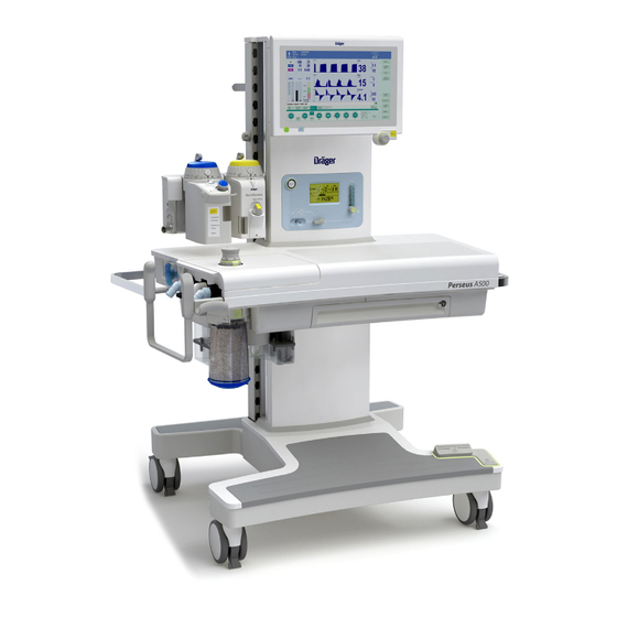
Page 16: Hardware
D Extensible writing tray with compartment for instructions for use (optional) E Central brake F Castors with central brake G Footrest H Trolley Anesthetic gas receiving system with flow indicator J CO absorber K APL valve Instructions for use Perseus A500 SW 1.1n... -
Page 17: Screen
3 steps (dark, medium, and bright) key for switching the device on or off Plug-in connection with Vapor View option for up to 3 vaporizers A Sensor unit B Illumination unit Instructions for use Perseus A500 SW 1.1n... -
Page 18: Breathing System
(G) on page 27 and (H) on page 28 C Inspiratory port D Bag elbow with circuit plug, e.g., to occlude the Y-piece during an automatic test E APL valve Instructions for use Perseus A500 SW 1.1n... -
Page 19: Side View From Left
Overview Side view from left A GCX rail for mounting additional workstation components B Strain relief for AGS hose, adjustable height C External fresh-gas outlet (optional) Instructions for use Perseus A500 SW 1.1n... -
Page 20: Device Column
A Column cover B GCX rail C Recesses for cables which lead e.g., into the device arms D Screw for closing the cable conduit lid E Tabs to hold the cable F Cable conduit Instructions for use Perseus A500 SW 1.1n... -
Page 21: Rear
C Strain relief for compressed gas hose D Connection for optional pole (38 mm) E Castor with castor brake F Gas cylinder holders (optional) with hook-and- loop strap G Interfaces H Rating plate Instructions for use Perseus A500 SW 1.1n... - Page 22 C Strain relief for compressed gas hose D Connection for optional pole (38 mm) E Castor with castor brake F Gas cylinder holders (optional) with hook-and- loop strap 2 mounting positions are possible. G Interfaces H Rating plate Instructions for use Perseus A500 SW 1.1n...
-
Page 23: Interfaces
A Device switch B Serial interfaces (COM 1 and COM 2) C USB interface D Network interface E Interface for work light (optional) F IEC connector (socket for power cable) G Potential equalization pin Instructions for use Perseus A500 SW 1.1n... -
Page 24: Gas Inlets
Gas inlets A Connections for gas pressure measurement for gas cylinders (optional) B Connections for central gas supply (N optional) C Connections for external gas cylinders (optional) D Label Advanced Cylinder Support (optional) Instructions for use Perseus A500 SW 1.1n... -
Page 25: Hanger Yokes (Optional) For Gas Cylinders With
Hanger yokes (optional) for gas cylinders with pin-index connections A Hanger yokes (optional) for gas cylinders with pin-index connections B Wrench for opening and closing the gas cylinder valves C Label Advanced Cylinder Support (optional) Instructions for use Perseus A500 SW 1.1n... -
Page 26: Auxiliary Power Sockets
Overview Auxiliary power sockets View with column cover removed: A Auxiliary power sockets, depending on equipment variant B Isolation transformer switch (optional) C Circuit breakers or fuses, depending on equipment variant Instructions for use Perseus A500 SW 1.1n... -
Page 27: Gas Mixing Unit (Electronically Controlled)
18 + button (O flush) Symbols for mains power supply and power supply from internal battery J Symbols for gas supply (O , Air, N O) through central supply and gas cylinders Instructions for use Perseus A500 SW 1.1n... -
Page 28: Gas Mixing Unit (Mechanically Controlled)
18 + button (O flush) J Symbols for mains power supply and power supply from internal battery K Symbol for programmed Auto On L Current time or time for Auto On Instructions for use Perseus A500 SW 1.1n... -
Page 29: Functional Scope
– Sevoflurane – Inspiratory O concentration – Desflurane – Inspiratory and expiratory CO concentrations – Apnea (pressure, flow, and CO – Occurrence of anesthetic gas mixtures – Degree of filling of the breathing bag Instructions for use Perseus A500 SW 1.1n... -
Page 30: Display On The Screen
After connecting a Dräger USB storage medium, a USB interface allows, e.g., the following actions: – Saving screen content as screenshot – Saving and loading device configurations – Saving system test results or protocols as text file Instructions for use Perseus A500 SW 1.1n... - Page 31 For more information, see ''Connections to IT networks'' on page 234. Support of Infinity ID accessories – Exchange interval monitoring – Anti-interchange security for breathing hoses For more information, see page 248. Instructions for use Perseus A500 SW 1.1n...
-
Page 32: Gas Flow Plan
P Blower module TurboVent 2 E Expiratory flow sensor F Patient G Expiratory pressure measurement H Patient gas measurement module Expiratory valve J PEEP/Pmax valve K APL valve L Anesthetic gas receiving system Instructions for use Perseus A500 SW 1.1n... -
Page 33: Gas Supply (Electronically Controlled Gas Mixer)
Gas supply (electronically controlled gas mixer) Add. O Aux. O A Gas supply (central supply or gas cylinders) B Gas mixer C Vaporizer flowmeter switch flush G Switch-over valve H Breathing system External fresh-gas outlet (optional) Instructions for use Perseus A500 SW 1.1n... -
Page 34: Gas Supply (Mechanically Controlled Gas Mixer)
Gas supply (mechanically controlled gas mixer) Aux. O A Gas supply (central supply or gas cylinders) B Flow control valves C Minimum O delivery D Total flow tube E Vaporizer flush flowmeter H Breathing system Instructions for use Perseus A500 SW 1.1n... -
Page 35: Operating Concept
Day and night colors........39 Selecting and setting ........39 Setting of parameters ........39 Canceling the setting procedure or the change procedure ............39 Activation of buttons ........39 Operating the flow control valves ....40 Instructions for use Perseus A500 SW 1.1n... -
Page 36: Main Screen
– Virtual flow tubes C Therapy controls – Prediction for anesthetic agents or FiO D Message field for information (optional) Information regarding configurable fields, E Buttons to expand and shrink the therapy bar. see page 146. Instructions for use Perseus A500 SW 1.1n... -
Page 37: Dialog Windows
(D). This window can be opened by touching the corresponding parameter field in the monitoring area. In the event of an alarm, the window can be opened automatically, see page 132. Instructions for use Perseus A500 SW 1.1n... -
Page 38: Color Concept
In the flow waveform, spontaneous breathing and currently not pressure support are displayed in a light brown available, func- color. tion activated Measured values whose specified accuracy cannot be maintained are displayed in dark gray. Gray Unavailable element Instructions for use Perseus A500 SW 1.1n... -
Page 39: Selecting And Setting
In the following chapters of this document, this – Selecting a view sequence of action is represented by simplified explanations: – Deactivating the CO alarms. – "Set the value." – "Touch the button." Instructions for use Perseus A500 SW 1.1n... -
Page 40: Operating The Flow Control Valves
Turn the flow control valve clockwise to the end stop. In the subsequent chapters of this document, the following is represented by simplified explanations: – "Open the flow control valve." – "Close the flow control valve." Instructions for use Perseus A500 SW 1.1n... -
Page 41: Assembly And Preparation
Observing resistance and compliance..... 62 Connecting a non-rebreathing system (optional)............63 Connecting or exchanging consumables ... 65 Single-use CO absorber ........ 65 Reusable CO absorber ........65 Water trap............66 Connecting the sample line ......67 Instructions for use Perseus A500 SW 1.1n... -
Page 42: Mounting Of Accessories
– Maximum weight on the left side of the device: – Variants with plug-in connections for 2 vaporizers: 25 kg (55 lbs) – Variants with plug-in connections for 3 vaporizers: 15 kg (33 lbs) – Maximum installation height: 1400 mm (55.1 Instructions for use Perseus A500 SW 1.1n... -
Page 43: Before First Operation
Only connect the power cable to power sockets with a protective ground, see ''Technical data''. Instructions for use Perseus A500 SW 1.1n... -
Page 44: Charging The Battery
The power supply out of strips to the auxiliary power sockets under the battery may be limited. the column covering. Do not expose the device to temperatures above 35 °C (95 °F) on a permanent basis. Instructions for use Perseus A500 SW 1.1n... -
Page 45: Connecting Additional Devices
Have the leakage accessories. current checked by service personnel. If the permissible value is exceeded, use a mains power socket on a wall instead of the auxiliary power socket of the device. Instructions for use Perseus A500 SW 1.1n... -
Page 46: Establishing Potential Equalization
Only connect with the approval of the respective device manufacturer. Have the leakage current checked by service personnel. If the permissible value is exceeded, disconnect the devices from the MEDIBUS interface. Instructions for use Perseus A500 SW 1.1n... -
Page 47: Transport Within The Hospital
1 Visually check the medical device for damage, Always move the device using two people. particularly the hoses and cables. 2 Any damage must be repaired by service personnel before using the device. Instructions for use Perseus A500 SW 1.1n... -
Page 48: Connecting The Gas Supply
Danger to the patient and user The device may be damaged if the strain relief of the compressed gas hoses is not used correctly. Use the strain relief of the compressed gas hoses correctly. Instructions for use Perseus A500 SW 1.1n... - Page 49 3 Set the full gas cylinders (C) into the gas cylinder holders and secure them with the hook-and-loop straps. CAUTION Risk of damage to the device When connecting the pressure reducers, ensure that they do not protrude beyond the device. Instructions for use Perseus A500 SW 1.1n...
- Page 50 12 Tighten the handle (H) on the cylinder holder (I). 13 Secure the gas cylinders (F) with hook-and- loop straps (K). If required, the gas cylinder valve (C) can be opened with the supplied wrench (G). Instructions for use Perseus A500 SW 1.1n...
-
Page 51: Mounting The Vaporizers
– Make sure that the connected vaporizers are hanging vertically. – When using D-Vapor vaporizers, make sure that the power cable is not pinched. – After mounting the vaporizers, perform a leakage test. Instructions for use Perseus A500 SW 1.1n... - Page 52 When connecting D-Vapor 3000 vaporizers 1 Connect the power cable to an auxiliary power socket under the Perseus column covering. 2 If needed, establish potential equalization. 3 If needed, stow the cable in the cable conduit. Instructions for use Perseus A500 SW 1.1n...
-
Page 53: Ensuring The Gas Supply
1 Connect the suction hose to the nozzle (A) of the receiving system. 2 Secure the suction hose (B) with strain relievers. 3 Connect the probe of the suction hose to the terminal unit of the scavenging system. Instructions for use Perseus A500 SW 1.1n... -
Page 54: Preparation For An Operation Day / After Cleaning And Sterilization
– Seals and sealing rings 2 Screw in the quick release screws (B) tightly with a clockwise rotation of 90°, e.g., with a coin. Instructions for use Perseus A500 SW 1.1n... - Page 55 1 Set the valve vertically on the upper housing of the breathing system. 2 Tightly screw the knurled nut (E) clockwise until it engages. Points (F) face the user when the breathing system is installed. Instructions for use Perseus A500 SW 1.1n...
-
Page 56: Inserting The Breathing System
– Infinity ID CLIC Absorber 800+ – CLIC Absorber 800+ – Infinity ID CLIC Absorber Free – CLIC Absorber Free 1 Insert the assembled breathing system (A) vertically into the breathing system mount. Instructions for use Perseus A500 SW 1.1n... -
Page 57: Mounting The Flexible Arm (Optional) Or The Bag Elbow
Mounting the flexible arm (optional) or the bag elbow The breathing bag can be mounted either on the flexible arm or, using the bag elbow and a breathing hose, mounted directly on the breathing system. Instructions for use Perseus A500 SW 1.1n... -
Page 58: Selecting And Connecting Patient-Specific Accessories
Use a patient-side filter or a filter at the inspiratory port. WARNING Risk of infection If no microbial filter is used, the breathing system may become contaminated with disease-causing germs. In this case, hygienically reprocess the breathing system after each patient. Instructions for use Perseus A500 SW 1.1n... - Page 59 Y-piece with a filter instead. In cases which preclude use of a microbial filter at the Y-piece, the ID functionality of the Infinity ID breathing hoses cannot be used. Instructions for use Perseus A500 SW 1.1n...
- Page 60 ''Table with recommended hose configurations'' on page 61. When attaching or removing the breathing hoses, always hold them at the connection sleeve and not at the spiral ribbing. Instructions for use Perseus A500 SW 1.1n...
- Page 61 If it is not possible to use an expi- ratory filter (e.g., due to an intrin- sic PEEP due to air trapping), hygienically reprocess the device after use with this patient, see page 184. Instructions for use Perseus A500 SW 1.1n...
-
Page 62: Breathing Bag
– Perform a leakage test after replacing breathing hoses, particularly flex hoses, vaporizers or soda lime. – Perform a leakage test after changing the length of flex hoses. Instructions for use Perseus A500 SW 1.1n... -
Page 63: Connecting A Non-Rebreathing System (Optional)
Resistance of the breathing system, see page 226. also be monitored for non-rebreathing systems. The sample line must be connected to the elbow and the water trap on Perseus. Instructions for use Perseus A500 SW 1.1n... - Page 64 Ensure the correct course of the sample gases. line. Do not use adapters. 2 Connect the fresh-gas hose of the non- rebreathing system to the external fresh-gas outlet (B). Instructions for use Perseus A500 SW 1.1n...
-
Page 65: Connecting Or Exchanging Consumables
Risk of chemical burns sealing rings on the absorber insert. Soda lime is caustic and is a strong irritant for eyes, skin, and airway. Handle this absorption material carefully and do not spill it. Instructions for use Perseus A500 SW 1.1n... -
Page 66: Water Trap
Observe the instructions for use of the water trap. CAUTION Risk of misleading data Silicon can get into the measuring cuvette and disrupt measurement. Do not spray the O-rings of the water trap holder with silicon spray. Instructions for use Perseus A500 SW 1.1n... -
Page 67: Connecting The Sample Line
Ensure the correct course of the sample line. Do not use adapters. NOTE Only use an original sample line, as other lines can change the technical data of the device. Instructions for use Perseus A500 SW 1.1n... -
Page 68: Getting Started
Getting started Switching on Perseus ........69 Checking for the readiness of operation ..70 Operation in case of emergency....71 Electronically controlled gas mixer ....71 Mechanically controlled gas mixer ....71 Instructions for use Perseus A500 SW 1.1n... -
Page 69: Switching On Perseus
139. WARNING Risk of device malfunction Some safety systems are only checked during start-up. Restart Perseus at least once per month to maintain proper functionality. Instructions for use Perseus A500 SW 1.1n... -
Page 70: Checking For The Readiness Of Operation
(D) is recommended as a remedy. To view details regarding the status of the system, touch the Details... button (B) or the Test... button (E), see page 103. Dräger recommends performing the system test every 24 hours. Instructions for use Perseus A500 SW 1.1n... -
Page 71: Operation In Case Of Emergency
8 As soon as the Standby page is displayed, start the therapy, see page 74. 9 Set O switch (A) to Aux. O to stop the increased fresh-gas flow. 10 Close the flow control valve (B). Instructions for use Perseus A500 SW 1.1n... -
Page 72: Operation
Flushing the breathing system ......101 measurement ..........88 Adjusting the current view ....... 89 Adjusting the sweep speed and the scales ..89 Changing the color mode and the screen brightness............90 Instructions for use Perseus A500 SW 1.1n... -
Page 73: Safety Information
Misdiagnosis or misinterpretation of the measured values or other parameters can endanger the patient. Do not make therapeutic decisions based solely on individual measured values and monitoring parameters. Therapeutic decisions must be made solely by the user. Instructions for use Perseus A500 SW 1.1n... -
Page 74: Starting The Therapy
I:E ratio is 1:1 for neonates and 1:2 for all other patient categories. Continuing a case Select to start the therapy with the settings of the last case: Touch the Continue case button (B). Instructions for use Perseus A500 SW 1.1n... -
Page 75: Checking The Patient Data
Check patient data Adjust patient data (A) if necessary. When these data are adjusted, appropriate therapy settings are suggested e.g., for tidal volume, respiratory rate, alarm limits. For more information, see page 248. Instructions for use Perseus A500 SW 1.1n... -
Page 76: Useful Tips
Risk of patient injury The use of minimum-flow or low-flow settings can lead to accumulation of metabolic by-products in the breathing system. If minimum-flow or low-flow settings are used, flush the breathing system regularly. Instructions for use Perseus A500 SW 1.1n... -
Page 77: Adjusting The Therapy
The points are vertically aligned and the valve Set the APL valve to the desired maximum head is raised. airway pressure. The pressure limitation is canceled and the valve is open for free spontaneous breathing. Instructions for use Perseus A500 SW 1.1n... -
Page 78: Using The O 2 Flush
Operate the vaporizer according to its Risk of increased anesthetic agent delivery instructions for use. Using the emergency O delivery (Add. O may cause an increased anesthetic gas concentration. Carefully monitor the gas mixture. Instructions for use Perseus A500 SW 1.1n... -
Page 79: Changing The Ventilation Mode
2 As needed, the expanded therapy bar can be ''Ventilation modes and effective parameters'' displayed using the buttons More (C) or (D); starting on page 239. here, additional parameters (Trigger sens., ∆Psupp, etc.) can be adapted to the patient. Instructions for use Perseus A500 SW 1.1n... -
Page 80: Special Forms Of Therapy
In the main menu bar, touch the Exit CBM machine. button. Properties of CBM mode: – All gas concentrations are measured independent of the respiratory phase. – The CO apnea and pressure apnea alarms are inactive. Instructions for use Perseus A500 SW 1.1n... -
Page 81: Pausing The Therapy / Using Pause
1 Start Pause operating mode. 2 Adjust the therapy control Timer if necessary. Returning to the previous mode 1 Touch the Resume ventilation button. 2 Confirm the ventilation mode. For more information, see page 132. Instructions for use Perseus A500 SW 1.1n... -
Page 82: Using Fields With Special Functions
The MAC values depend on the age of the patient. The values specified in the table apply to a patient age of 40 years. 1 MAC corresponds to: (in 100 % O Halothane 0.77 Vol% Enflurane 1.7 Vol% 40 years Instructions for use Perseus A500 SW 1.1n... -
Page 83: Prediction Of Anesthetic Gas Concentration (Optional)
The anesthetic gas prediction is not suitable for the following patients: – Alcohol dependents – Greatly overweight patients (BMI >35) – Patients with ASA ≥IV – Patients with severe circulatory disorders or a cardiopulmonary bypass Instructions for use Perseus A500 SW 1.1n... -
Page 84: Prediction Of The Inspiratory O Concentration (Optional)
(the so-called on the basis of a displayed O prediction. "what if..." function). When the value is altered with the therapy control, the lines move and show a preview of the predicted concentration. Instructions for use Perseus A500 SW 1.1n... -
Page 85: Econometer (Optional)
3 To reset the countdown to zero, touch the immediately Reset button (A). An inadequately filled breathing bag can trigger the Fresh gas low or leakage or Emergency air inlet activated alarms, for example. Instructions for use Perseus A500 SW 1.1n... -
Page 86: Volumeter
60 seconds. The measured values are displayed An insufficient fresh-gas flow can trigger the Fresh for 4 minutes and then deleted. gas low or leakage or Emergency air inlet activated alarms, for example. Instructions for use Perseus A500 SW 1.1n... -
Page 87: Organizing The Screen Display
In addition to the standard view, the four additional parameter fields (D), (E), (F), and (G) are A Opens the standard view displayed. B Opens the expert view The views can be renamed, see page 127. Instructions for use Perseus A500 SW 1.1n... -
Page 88: Using Loops
The value displayed here for Cdyn is updated more frequently and thus may differ from the value displayed in the Trends/Data dialog window. 1 Open the Views dialog window. 2 Touch the Limits & units button. Instructions for use Perseus A500 SW 1.1n... -
Page 89: Adjusting The Current View
Restoring the current view The changes in the current view can be reset to the saved standard. 1 Open the Views dialog window. 2 Touch the Restore current view button. Instructions for use Perseus A500 SW 1.1n... -
Page 90: Displaying Additional Data
2 Touch the Values tab (A). The vertical tabs (B) display different combinations During operation, measured values for ventilation, of parameters. gases, and the device are available in tabular overviews. Trends/Data 1 Open the Trends/Data dialog window. Instructions for use Perseus A500 SW 1.1n... -
Page 91: Logbook
1 Open the Trends/Data dialog window. Use the rotary knob to move the cursor (G). 2 Touch the Graphical trends (A) or Tabular trends tab (B). Touch the corresponding area on the screen. Instructions for use Perseus A500 SW 1.1n... -
Page 92: Setting The Sound Volume
Risk of operation error The acoustic alarm signals might not be heard if functions such as "Breathing sound" are used or when operating in a noisy environment. Always set the alarm tone to be sufficiently loud. Instructions for use Perseus A500 SW 1.1n... -
Page 93: Adjusting The Alarms
The Quick setup window opens. Quick setup Manual setting 1 Set the upper alarm limits (D). 2 Set the lower alarm limits (E). 2 Set the upper alarm limit (A). 3 Set the lower alarm limit (B). Instructions for use Perseus A500 SW 1.1n... -
Page 94: Activating Or Deactivating Co
The monitoring is automatically activated as soon as the following conditions are met: – Anesthetic gas is administered. – The inspiratory xMAC value is greater than the expiratory xMAC value. – The expiratory xMAC value reaches approximately 0.3. Instructions for use Perseus A500 SW 1.1n... -
Page 95: Deactivation Of Automatic Xmac Monitoring
In CBM mode the lower alarm limit is adjusted both upwards and downwards so that no alarm is issued during this time. Similarly, the value is not limited to 1.0 during this time. Instructions for use Perseus A500 SW 1.1n... -
Page 96: Changing The Patient Data
The screen contents can be exported to a USB flash drive as a screenshot. Touch the Export screenshot button in the main menu bar. The screen contents are saved to the storage medium as a ".bmp" file. Instructions for use Perseus A500 SW 1.1n... -
Page 97: Other Settings
(e.g., for intentional reduction of the body temperature of the patient). 1 Open the System setup dialog window. 3 To switch the heating on or off, touch the corresponding button (B). Instructions for use Perseus A500 SW 1.1n... -
Page 98: Creating Additional Logbook Entries
MV, Pmean, PIP, Pplat, PEEP, FiO , exp. concentration of the primary anesthetic gases, and – Adjustable time intervals – Alarms with high or medium priorities 1 Open the System setup dialog window. Instructions for use Perseus A500 SW 1.1n... -
Page 99: Ending The Therapy
– Before beginning laser surgery or electrosurgery, flush with sufficient air (<25 % O ), and flush beneath the surgical drapes as well. – Close the flow control valve of the O flowmeter. Instructions for use Perseus A500 SW 1.1n... -
Page 100: Patient Change
''Reprocessing list'' on page 191. Vaporizer filling level Checking or replacing consumables Check the vaporizer filling level at the sight glass. If necessary, fill the vaporizer. Prerequisite: The device is in Standby mode Instructions for use Perseus A500 SW 1.1n... -
Page 101: Checking The System
3 Prepare the device according to the displayed checklist. 4 Touch the Start button. 5 After flushing is complete, touch the OK button to change to the Standby mode, or end the flushing prematurely with Cancel. Instructions for use Perseus A500 SW 1.1n... -
Page 102: System Test
Performing the tests ........105 Fully automatic tests........105 Leakage assistant ........... 106 Processing the checklist ......106 Checking the gas supply ......... 106 Checking the vaporizers........108 Checking the breathing system ....... 108 Miscellaneous..........110 Instructions for use Perseus A500 SW 1.1n... -
Page 103: Information On The Availability Of Individual Device Functions
Thus, more attention is required during operation. Perform the system test every day. If the system test is canceled during execution, perform it again as soon as possible. Instructions for use Perseus A500 SW 1.1n... -
Page 104: Available Test Types
(after occurrence of breathing circuit support the manual check. problems with leakage Changes are immediately visi- – On suspicion of leakage during automatic tests) ble. at vaporizer – Leakage test of a connected vaporizer Instructions for use Perseus A500 SW 1.1n... -
Page 105: Performing The Tests
Accepted irregularities prevent the total result of Test progress and test results are indicated by the the system test from indicating "fully operational" progress display. and are protocoled in the logbook. 4 End the test with the OK button. Instructions for use Perseus A500 SW 1.1n... -
Page 106: Processing The Checklist
Risk due to impermissible gas supply Do not use any O concentrators. Using oxygen supplies with less than 100 % may cause incorrect gas composition. When using O , only use 100 % O Instructions for use Perseus A500 SW 1.1n... - Page 107 Cylinder Support, the gas cylinder valves can 4 Reset O switch (C) to Aux. O position. remain open during operation. These devices are identified by an appropriate label near the gas inlets, see page 24. Instructions for use Perseus A500 SW 1.1n...
-
Page 108: Checking The Vaporizers
2 Breathing system cover is in place. 3 Hoses (A) and filters, e.g., at the Y-piece (B), For each vaporizer, check: are connected properly. 1 The locking lever (A) points left, indicating the vaporizer is locked. Instructions for use Perseus A500 SW 1.1n... - Page 109 Do not leave the flow control valves open for an unnecessarily long period of time. NOTE Only perform leakage tests with CLIC absorber locked into place because this affects the system compliance values. Instructions for use Perseus A500 SW 1.1n...
-
Page 110: Miscellaneous
When Infinity ID functionality is not configured: – Water trap will not be detected. Update the exchange date manually: In the line Last water trap change:, touch the Reset button when a new water trap is installed. Instructions for use Perseus A500 SW 1.1n... -
Page 111: Ending Operation
Preparing the device for automatic switch-on, including system test (Auto On option).... 112 Flushing and drying the breathing system (Flush & Dry function)........113 Storing the device..........113 Disconnecting the mains power supply ... 113 Instructions for use Perseus A500 SW 1.1n... -
Page 112: Switching Off The Device
6 Shut down the device when the preparatory test is complete. When the automatic start-up is activated, the corresponding symbol appears in the status display, see page 27. For more information, see page 140. Instructions for use Perseus A500 SW 1.1n... -
Page 113: Flushing And Drying The Breathing System (Flush & Dry Function)
Storing the device To store Perseus 1 Set device switch to position 0. 2 Disconnect from mains power supply if necessary. Disconnecting the mains power supply Pull out the mains plug. Instructions for use Perseus A500 SW 1.1n... -
Page 114: Alarms
Resetting the Apnea (no CO ) alarm ....121 Alarm delay and alarm escalation ....121 Activation of alarms after breath detection 124 Intelligent alarm behavior......124 Combined alarms ..........124 Suppressed alarms ......... 124 Instructions for use Perseus A500 SW 1.1n... -
Page 115: Display Of Alarms
Dräger Vapor 3000 if their cause can be remedied by adjusting or refilling the vaporizer, e.g.: – Inspiratory xMAC high – Filling level of vaporizer low – Vaporizer open Instructions for use Perseus A500 SW 1.1n... -
Page 116: Response To Alarms
''Troubleshooting'', see page 162. Open the Alarms dialog window and touch the Current alarms tab (A). Alarms 2 In the list (B), touch the corresponding alarm or select it with the rotary knob. Instructions for use Perseus A500 SW 1.1n... -
Page 117: Suppressing The Alarm Tone
While the alarm tone is suppressed, only new alarms with a higher alarm priority or a higher internal priority rating are acoustically signaled, see page 162. Switching on the suppressed alarm tone prematurely Press the Audio paused key again. Instructions for use Perseus A500 SW 1.1n... -
Page 118: Downgrading And Acknowledging Alarm Messages
Use the rotary knob or the arrow buttons to scroll the cursor up (B) or down (C). The alarm history is deleted when Perseus is shut down or a new case is started. Instructions for use Perseus A500 SW 1.1n... -
Page 119: Adjusting The Alarm Limits
Quick setup 2 Adjust the value (B) and confirm. Perseus can be configured so that the Quick setup window opens automatically in the event of an alarm, see page 132. Instructions for use Perseus A500 SW 1.1n... -
Page 120: Adopting Alarm Settings When Changing The Ventilation Mode
MV low page 133 page 133 Apnea (no flow) Apnea (no pres- sure) 1) This alarm is only activated when the MV low alarm limit is also activated. Instructions for use Perseus A500 SW 1.1n... -
Page 121: Alarm Delay And Alarm Escalation
After two successive etCO respiratory phases high and 15 seconds Inspiratory N O high inAgent low After two successive respiratory phases and 15 seconds after 30 seconds if no respiratory phases are detected Instructions for use Perseus A500 SW 1.1n... - Page 122 (configurable, see page 132) No CO detected >60 s Inspiratory tidal volume high After 3 successive Tidal volume not achieved breaths > 15 seconds above Airway press. continuously high the manually or auto- matically set limit Instructions for use Perseus A500 SW 1.1n...
- Page 123 "Apnea (no flow)" or "Apnea Breathing bag almost Fresh gas low or leakage Breathing bag empty (no pressure)" empty in case of the addi- tional alarm "Emer- gency air inlet activated" Instructions for use Perseus A500 SW 1.1n...
-
Page 124: Activation Of Alarms After Breath Detection
If this measurement function monitors physiological parameters, alarms based on these parameters will not be generated. Example: Fault Displayed alarm Non-generated alarm measurement is faulty Sample line occluded Apnea (no CO Instructions for use Perseus A500 SW 1.1n... -
Page 125: Configuration
................ 145 Manual entry of the license key ....... 146 Activating the licensed application....146 Overview of the configurable screen contents............146 Waveforms and associated parameter fields .. 146 Miscellaneous parameter fields ....... 147 Instructions for use Perseus A500 SW 1.1n... -
Page 126: Device Settings
The respective factory settings are entered or marked in bold format. System setup > Screen layout Vertical tab "General settings" Setting range Headline/ Description Parameter Display mode Day light; Day dark; Night Setting the color mode, see page 39 Instructions for use Perseus A500 SW 1.1n... - Page 127 Auto; Specify O waveform scale. 0 to 100; 15 to 35; 25 to 45; 35 to 55; 45 to 65; 55 to 75; 65 to 85; 75 to 95; 85 to 105 Instructions for use Perseus A500 SW 1.1n...
-
Page 128: System Setup > Alarms
Description Parameter Alarm limits for ventilation and gases for each patient category 19 to 100; 19 to 100; 19 to 100; Inspiratory oxygen fraction 18 to 99 18 to 99 18 to 99 Instructions for use Perseus A500 SW 1.1n... - Page 129 [%]; [kPa] inDes 0.1 to 20.0 0.1 to 20.0 0.1 to 20.0 Desflurane [%]; [kPa] 12.0 17.2 18.8 inDes Off; Off; Off; 0.0 to 19.9 0.0 to 19.9 0.0 to 19.9 [%]; [kPa] Instructions for use Perseus A500 SW 1.1n...
- Page 130 Off; 0.00 to 8.40 0.00 to 8.40 0.00 to 8.40 [%]; [kPa] Vertical tab "Alarm tone volume" Setting range Headline/ Description Parameter Alarm tone volume 10 to 100 Set the alarm tone volume. Instructions for use Perseus A500 SW 1.1n...
- Page 131 / Pressure Support (optional) and Pause), a further 20 percentage points are added to the configured value. VTi +[%] Off; 20 to 80 The setting for this parameter has no effect in volume-controlled ven- tilation modes. Instructions for use Perseus A500 SW 1.1n...
- Page 132 Pause mode has expired. Default value for 0:00 to 60:00 0:00 to 60:00 0:00 to 60:00 Specify standard duration for "Timer" [mm:ss] Pause. 2:00 1:00 0:30 Instructions for use Perseus A500 SW 1.1n...
- Page 133 Alarm limits. Deactivate the alarm limit in cardiac bypass mode (CBM)? high Yes; No Specify alarm behavior in CBM mode. MV low Yes; No MV high Yes; No inAgent low Yes; No Instructions for use Perseus A500 SW 1.1n...
- Page 134 [psi]: Off; 218 to 450 [bar]; [kPax100]: Off; 15 to 31 [psi]: Off; 218 to 450 [bar]; [kPax100]: Off; 15 to 31 [psi]: Off; 218 to 450 Instructions for use Perseus A500 SW 1.1n...
-
Page 135: System Setup > Therapy
MV high, MV minimal: 0.3 L/min low, and VTi high: VTi high = VT x (1 + offset) MV high = VT x RR x (1 + offset); minimal: 2.0 L/min Instructions for use Perseus A500 SW 1.1n... - Page 136 3 to 25 [1/min] %Tplat 20 to 60 20 to 60 20 to 60 Trigger sens. 0.3 to 15 0.3 to 15 0.3 to 15 [L/min] Sync. On; Off On; Off On; Off Instructions for use Perseus A500 SW 1.1n...
- Page 137 Do not set this value too small; recommended is, e.g., 200 for adults, 100 for pediatric patients, and 50 for neonates. Carrier gas Air; N Air; N Air; N Set the carrier gas. Instructions for use Perseus A500 SW 1.1n...
- Page 138 On; Off Switch breathing system heating heating on or off. Auto wake-up On; Off The Start dialog window opens automatically when ventilation activity is detected (e.g., by squeezing the breathing bag sev- eral times). Instructions for use Perseus A500 SW 1.1n...
-
Page 139: System Setup > System
However, this decreases the life span of the patient gas measure- ment module. System name Rename Change system name to, e.g., enter the installation site. Device name (up to 16 alphanumeric charac- ters) Perseus Instructions for use Perseus A500 SW 1.1n... - Page 140 Flush function is deactivated. Flush & Dry dura- Off; 5 to 30 Set the duration of flushing and tion before shut- drying when the device is shut down [min] down. Off: Drying function is deactivated. Instructions for use Perseus A500 SW 1.1n...
- Page 141 – Nitrous oxide cannot be deliv- ered. – Measured nitrous oxide con- centration is only displayed when not equal to zero. Off: – Nitrous oxide can be delivered. – Measured nitrous oxide con- centration is continuously dis- played. Instructions for use Perseus A500 SW 1.1n...
- Page 142 XXX . XXX . XXX . XXX same IP address from the DHCP server. Restart the device after each change to the network settings. The network settings are not affected by a reset to factory set- tings. Instructions for use Perseus A500 SW 1.1n...
- Page 143 – Messages are suppressed. Exchange interval [days] Breathing circuit Off; 1 to 9 Set the exchange intervals for Infinity ID accessories. Water trap Off; 28 Flow sensors Off; 1 to 180 absorber Off; 1 to 28 Instructions for use Perseus A500 SW 1.1n...
-
Page 144: Transferring Device Configurations
Perseus devices of the same version in this way. Prerequisite: The USB flash drive is connected to the USB interface. Open System setup > Im/Export config. > Im/Export config. (A). Instructions for use Perseus A500 SW 1.1n... -
Page 145: Activating Applications
Open System setup > Applications > Prerequisite: A USB flash drive with valid licenses Applications (A). for this Perseus anesthesia machine is connected to the USB interface. Touch the Load from USB button (B). Instructions for use Perseus A500 SW 1.1n... -
Page 146: Overview Of The Configurable Screen Contents
Waveforms and associated parameter fields Paw (3) Volume-controlled modes: Parameters PIP, Pplat, PEEP etCO All other modes: Parameters PIP, Pmean, PEEP in/et Paw (4) Parameters PIP, Pplat, Pmean, PEEP: in/et, RR Volume MV, VT, RR Volume Instructions for use Perseus A500 SW 1.1n... -
Page 147: Miscellaneous Parameter Fields
RR "Empty" Miscellaneous parameter fields Compliance trend Cdyn PEEP The value displayed here for Cdyn is updated more frequently and thus may differ from the value displayed in the Trends/Data dialog field. Instructions for use Perseus A500 SW 1.1n... - Page 148 Do not make therapy decisions based solely Pplat on the displayed numerical value. Only the trend curve can be used for therapeutic decisions. Pmean PEEP MV×CO2 MVmand, spon Mand Spon ∆VT ∆VT Instructions for use Perseus A500 SW 1.1n...
- Page 149 Do not make therapy decisions based solely on the displayed numerical value. Only the trend curve can be used for therapeutic decisions. Instructions for use Perseus A500 SW 1.1n...
- Page 150 Stopwatch Required FG flow Stopwatch Start Total flow Efficient Countdown timer Gases in/et Countdown Gases in/et Econometer trend (optional) Gas supply Gas supply Econometer trend prediction (optional) Volumeter FiO2 prediction Volumeter Start Volume Instructions for use Perseus A500 SW 1.1n...
- Page 151 Risk of mix-up In some countries, the representation and order of the virtual flow tubes on the screen may differ from that illustrated here. Pay attention to the labeling of the virtual flow tubes. Instructions for use Perseus A500 SW 1.1n...
- Page 152 Configuration When the Agent prediction parameter field is displayed, the flow tubes will be displayed at reduced size: Instructions for use Perseus A500 SW 1.1n...
-
Page 153: Troubleshooting
(AGS) ..........161 Replacing the anesthetic gas receiving system (AGS)............... 161 Problems with the pressure reducers ..162 Problems with the Vapor View option ..162 Alarm – Cause – Remedy......162 Instructions for use Perseus A500 SW 1.1n... -
Page 154: Leakages
– The filling or emptying connections on the vaporizer are leaking or are open. The vaporizer is incorrectly fitted. The O-ring is missing or damaged. The control dial is not at the 0 position. Instructions for use Perseus A500 SW 1.1n... -
Page 155: Power Supply Failure
Ensure an alternative power supply for status display. connected devices. The breathing system heating is deactivated during battery operation. The peak inspiratory pressure PIP may be limited, but it will equal at least 55 hPa (cmH Instructions for use Perseus A500 SW 1.1n... -
Page 156: Mains Power Supply Failure And Empty Batteries
– If necessary, wait at most 2 minutes for the 5 Ensure corresponding substitute monitoring. circuit breaker to cool. – Press the key on the circuit breaker back in or operate the switch on the isolation transformer. 4 Restore mains power supply. Instructions for use Perseus A500 SW 1.1n... -
Page 157: Failure Of The Gas Supply
Air or 100 % O can be set as carrier gas. With the mechanically controlled gas mixer, open the corresponding flow control valve of the substitute gas. Instructions for use Perseus A500 SW 1.1n... -
Page 158: Failure Of Fresh-Gas Delivery (Electronically Controlled Gas Mixture)
To prevent permanent acoustic alarm signals, downgrade the priority of the Fresh-gas delivery failure alarm, if necessary. If necessary, perform ventilation with ambient air, see ''Complete failure of the gas supply'' on page 157. Instructions for use Perseus A500 SW 1.1n... -
Page 159: Ventilator Failure
If there is an additional malfunction of the inspiratory pressure sensor, the system automatically switches to the non-synchronized Pressure Control - CMV mode. In either case, check the ventilation settings and adjust as needed. Instructions for use Perseus A500 SW 1.1n... -
Page 160: Screen Fault/User Interface Failure
– If fresh gas still is not delivered or manual ventilation is not possible, close the flow control valve of the O flowmeter. – Disconnect the patient from the device and use a replacement device! Instructions for use Perseus A500 SW 1.1n... -
Page 161: Problems With The Anesthetic Gas Receiving System (Ags)
3 Remove the three screws (A). 4 Dispose of the AGS. Assembling the anesthetic gas receiving system (AGS) Follow the above steps in reverse order to assemble the new AGS. Instructions for use Perseus A500 SW 1.1n... -
Page 162: Problems With The Pressure Reducers
Caution Yellow The priority of the alarm messages is indicated by different background colors. Note Cyan In the Current alarms table and Alarm history table, the priority of the alarm messages is also Instructions for use Perseus A500 SW 1.1n... - Page 163 !!! 110 Air supply low Central supply pressure and Check central Air supply or cylinder pressure are low. use cylinder. Use "ALARM RESET" to downgrade alarm priority. Instructions for use Perseus A500 SW 1.1n...
- Page 164 Start manual ventilation! Check ventilation settings. Check spontaneous breathing ability of the patient. !! 255 Apnea No breathing or ventilation. Start manual ventilation! Check ventilation settings. Check spontaneous breathing ability of the patient. Instructions for use Perseus A500 SW 1.1n...
- Page 165 Check alarm limit. Fresh-gas flow is insufficient, Check fresh-gas settings and breathing bag is blocked or position of breathing bag. positioned incorrectly. The breathing hoses are Check breathing circuit and blocked or leaking. tube. Instructions for use Perseus A500 SW 1.1n...
- Page 166 Battery temperature high The battery temperature is Ensure that the system is high. Charging of the battery connected to the mains power has been suspended to pro- supply. tect it from damage. Instructions for use Perseus A500 SW 1.1n...
- Page 167 Breathing system heating The breathing system heating Check breathing circuit for failure has failed. condensation. Increase fresh- gas flow if necessary. Call DrägerService. An internal temperature sen- Call DrägerService. sor is faulty. Instructions for use Perseus A500 SW 1.1n...
- Page 168 Central O supply low Central supply pressure is Check central supply. low. absorber expired Accessory has been used too Replace the accessory if nec- long. essary. Use "ALARM RESET" to acknowledge alarm. Instructions for use Perseus A500 SW 1.1n...
- Page 169 Perform the breathing sys- calibrated The breathing system has tem test. been replaced or discon- nected since last calibration. Failure of the flow sensor. Replace the flow sensor and perform the breathing system test. Instructions for use Perseus A500 SW 1.1n...
- Page 170 The flow sensors have not Perform the breathing sys- required been calibrated since the tem test. device was powered on. The last calibration of the flow sensors was performed more than 24 hours ago. Instructions for use Perseus A500 SW 1.1n...
- Page 171 Leakage or disconnection. Check the breathing circuit for tight connections and leak- ages. Check tube or mask. Use "ALARM RESET" to downgrade alarm priority. Instructions for use Perseus A500 SW 1.1n...
- Page 172 An incompatible accessory is Check accessory. compatible connected. Use "ALARM RESET" to acknowledge alarm. Infinity ID water trap not An incompatible accessory is Check accessory. compatible connected. Use "ALARM RESET" to acknowledge alarm. Instructions for use Perseus A500 SW 1.1n...
- Page 173 Perform the breathing sys- calibrated The breathing system has tem test. been replaced or discon- nected since last calibration. Failure of the flow sensor. Replace the flow sensor and perform the breathing system test. Instructions for use Perseus A500 SW 1.1n...
- Page 174 Check vaporizer and fresh- high concentration has exceeded gas settings. the upper alarm limit. !!! 255 Inspiratory sevoflurane Inspiratory anesthetic gas Check vaporizer and fresh- high concentration has exceeded gas settings. the upper alarm limit. Instructions for use Perseus A500 SW 1.1n...
- Page 175 Ambient temperature is too Check ambient conditions. high. A fan is faulty. Call DrägerService. Excessive ventilation set- Check ventilation settings. tings are applied (e.g., high respiratory rate, high inspira- tory pressure, short slopes). Instructions for use Perseus A500 SW 1.1n...
- Page 176 (e.g., VT, Pinsp, RR). In Pressure Support, correct the trigger threshold if neces- sary. Check alarm limit. Flow measurement is inaccu- Replace the expiratory flow rate. sensor if necessary and per- form the breathing system test. Instructions for use Perseus A500 SW 1.1n...
- Page 177 60 seconds. Use "ALARM RESET" to acknowledge alarm. !!! 200 No fresh-gas flow No fresh-gas flow is set. Open the flow control valves. Use "ALARM RESET" to downgrade alarm priority. Instructions for use Perseus A500 SW 1.1n...
- Page 178 Use "ALARM RESET" to downgrade alarm priority. On/Standby key stuck Key is stuck or was pressed Ventilation performance is not for more than 10 seconds. affected. If the problem persists, call DrägerService. Instructions for use Perseus A500 SW 1.1n...
- Page 179 !! 100 Pressure sensor failure There is condensate in the Check the breathing hoses. breathing hoses. Sensor calibration failed. Perform the system test. If the problem persists, call DrägerService. Instructions for use Perseus A500 SW 1.1n...
- Page 180 !! 100 Synchronized ventilation Inspiratory efforts of the Check ventilation settings. failure patient cannot be detected Change to a non-synchro- due to faulty sensors. nized ventilation mode. Change to MAN/SPON mode and ventilate manually. Instructions for use Perseus A500 SW 1.1n...
- Page 181 TurboVent 2 not connected The TurboVent 2 blower mod- Insert the TurboVent 2 blower ule is not connected. module. Use "ALARM RESET" to downgrade alarm priority. !!! 100 Unknown alarm Error in the internal alarm Check patient condition. system. Call DrägerService. Instructions for use Perseus A500 SW 1.1n...
- Page 182 Water trap disconnected? Infinity ID water trap is not Check water trap. correctly connected. Water trap expired Accessory has been used too Replace the accessory if nec- long. essary. Use "ALARM RESET" to acknowledge alarm. Instructions for use Perseus A500 SW 1.1n...
- Page 183 !! 100 Y-piece is open or not con- The Y-piece is open or not Make sure that the Y-piece is nected connected during flush or occluded. Flush & Dry procedure. Instructions for use Perseus A500 SW 1.1n...
-
Page 184: Cleaning, Disinfection And Sterilization
Semi-critical medical devices ......188 Visual check ............ 190 Sterilization............190 Reprocessing list .......... 191 Non-critical medical devices......191 Semi-critical medical devices ......193 Assembling the parts........194 Before using on patients again ....194 Instructions for use Perseus A500 SW 1.1n... -
Page 185: Disassembly
Leave the inner and outer sealing rings on the absorber insert. 4 Remove the breathing bag. 5 Remove the breathing circuit and the filter. 6 Unscrew the flexible arm for the breathing bag (optional). Instructions for use Perseus A500 SW 1.1n... -
Page 186: Note On Removable Accessories, Consumable Parts, And Attached Parts
Reuse, reprocessing or sterilization can result in them. failure of the accessory and injury to the patient. Replace the sample lines regularly, see Do not reuse, reprocess or sterilize disposable page 193, table ''Semi-critical medical items. devices''. Instructions for use Perseus A500 SW 1.1n... -
Page 187: Reprocessing Procedures
– Dismozon pur from Bode Chemie – Mikrobac from Bode Chemie (for temperature measurement nozzles and pneumatic connections in the breathing system mount) Semi-critical medical devices Manual cleaning: – Neodisher LM2 (2 %, 20 minutes) from Dr. Weigert Instructions for use Perseus A500 SW 1.1n... -
Page 188: Semi-Critical Medical Devices
Running water and typical cleaning agents based intactness. on mildly alkaline compounds are recommended for manual cleaning. Position of the incident flow grills, see chapter ''Manual disinfection''. Instructions for use Perseus A500 SW 1.1n... - Page 189 1 Brush the components for 1 minute and wait briefly. For machine cleaning and disinfection of components that conduct breathing-gas, use a washer-disinfector in accordance with ISO 15883, preferably with a cart for anesthesia and ventilation accessories. Instructions for use Perseus A500 SW 1.1n...
-
Page 190: Visual Check
(e.g., corrosive effects of disinfectant residues are greatly increased by autoclaving), wear can increase to distinctly reduce life span. Exchange any components exhibiting signs of external wear (e.g., cracks, deformation, discoloration, delamination). Instructions for use Perseus A500 SW 1.1n... -
Page 191: Reprocessing List
– Table surface – APL valve – Grip bar under table – Drawer handles – Writing tray – Mounting rails on both sides – CLIC adapter – CLIC absorber, Infinity ID CLIC absorber Instructions for use Perseus A500 SW 1.1n... - Page 192 – Network cables and data cables – Compressed gas hoses – Pressure reducers – Gas cylinders – Outer and inner surfaces of draw- – AGS – Sensor unit and illumination when Vapor View option is installed Instructions for use Perseus A500 SW 1.1n...
-
Page 193: Semi-Critical Medical Devices
Y-piece and the filters are fitted to the breathing system. Breathing system Weekly Only out- Only out- mount side side Flexible arm for breath- Weekly Only out- ing bag (optional) side Instructions for use Perseus A500 SW 1.1n... -
Page 194: Assembling The Parts
Before using on patients again 1 Assemble the device components, see ''Preparation for an operation day / after cleaning and sterilization'' on page 54. 2 Check operational readiness, see ''Testing the system'' on page 103. Instructions for use Perseus A500 SW 1.1n... -
Page 195: Maintenance
Maintenance Maintenance Overview............196 Inspection............196 Remote Service ..........197 Safety checks ..........197 Preventive maintenance ....... 198 Table of maintenance intervals......198 Repairs ............199 Instructions for use Perseus A500 SW 1.1n... -
Page 196: Overview
Interval Responsible personnel Inspection and safety checks Every 12 months Service personnel 1) Designation applies to the Federal Republic of Germany; corresponds to the “Recurring safety inspection” in the Federal Republic of Austria Instructions for use Perseus A500 SW 1.1n... -
Page 197: Remote Service
– Anesthetic gas measurement: Isoflurane, 1 Vol% Sevoflurane, 1 Vol% Accuracy ±0.35 Vol% – N O measurement, 70 Vol% Accuracy ±7.6 Vol% – CO measurement, 5 Vol% Accuracy ±0.83 Vol% Instructions for use Perseus A500 SW 1.1n... -
Page 198: Preventive Maintenance
Infinity ID exchange interval Water trap If required, if soiled, or Replace, see page 66 Users according to the config- ured Infinity ID exchange interval Instructions for use Perseus A500 SW 1.1n... -
Page 199: Repairs
Replace Service personnel (2 pieces) Or after determination of Replace Experts remaining capacity Repairs Dräger recommends that all repairs are carried out by DrägerService and that only authentic Dräger repair parts are used. Instructions for use Perseus A500 SW 1.1n... -
Page 200: Disposal
Disposal Disposal Disposing of the medical device....201 For countries subject to the EU Directive 2002/96/EC ............. 201 Disposing of accessories ......201 Instructions for use Perseus A500 SW 1.1n... -
Page 201: Disposing Of The Medical Device
– Water trap – CLIC absorber, Infinity ID CLIC absorber – Soda lime Dispose on the following articles according to hospital hygiene regulations: – Sample line – Soda lime dust filter – AGS Instructions for use Perseus A500 SW 1.1n... -
Page 202: Technical Data
Flow characteristic curves for pressure reducers ............228 EMC declaration ..........229 General information......... 229 Electromagnetic transmission ......230 Electromagnetic immunity ....... 230 Recommended safety clearance for portable and mobile high-frequency communication equipment............232 Instructions for use Perseus A500 SW 1.1n... -
Page 203: General Information
20 to 95 %, without condensation concentration 300 to 1000 ppm Altitude Up to 4000 m (13123 ft) During storage and transport Temperature Device without battery -20 °C to 60 °C (-4 °F to 140 °F) Instructions for use Perseus A500 SW 1.1n... -
Page 204: Fresh-Gas Delivery
25 to 100 Vol% (carrier gas N ±5 % or ±2 Vol% (the larger value applies) Fresh-gas flow FG flow Off; 0.2 to 15 L/min; ±10 % or ±50 mL/min (the larger value applies) Instructions for use Perseus A500 SW 1.1n... -
Page 205: Fresh-Gas Delivery (Mechanically Controlled Gas Mixer)
±10 % of the set value or ±100 ms (the larger value applies) Maximum inspiratory time for supported breaths (fixed setting) Patient category "adult" 4 s or 1 / (2 x RRapn) (the smaller value applies) Instructions for use Perseus A500 SW 1.1n... - Page 206 Results from the VT / Pinsp and Ti settings Pressure-related settings Inspiratory pressure Pinsp PEEP +1 to 80 hPa (cmH ±10 % of the set value or ±2 hPa (cmH O) (the larger value applies) Instructions for use Perseus A500 SW 1.1n...
-
Page 207: Breathing System
Typically 2.18 L Compliance (without breathing circuit) In MAN / SPON mode Typically 2.18 mL/hPa (mL/cmH In automatic ventilation modes Typically 0.28 mL/hPa (mL/cmH Volume of absorber container Reusable CO absorber, filled 1.5 L Instructions for use Perseus A500 SW 1.1n... - Page 208 Maximum compliance: 6.0 mL/hPa (mL/cmH Maximum resistance: 6 hPa at 60 L/min Maximum length 200 cm (78.7 in) 350 cm (137.8 in) (with restrictions for compli- ance correction and pressure metering accu- racy) Instructions for use Perseus A500 SW 1.1n...
-
Page 209: External Fresh-Gas Outlet
At lower end of restricted range 14 L/min Maximum fresh-gas flow to prevent contaminat- ing ambient air For external breathing systems (normal 16 L/min range) For external breathing systems (restricted 5 L/min range) Instructions for use Perseus A500 SW 1.1n... -
Page 210: Measurement Systems And Displays
The measured volumes are also corrected by the sampling flow of the built-in patient-gas mea- surement module as soon as CO respira- tory phases are detected. Tidal volume Inspiratory Expiratory Instructions for use Perseus A500 SW 1.1n... - Page 211 0 to 150/min Accuracy ±1 /min or 10 % (the larger value applies) Resolution of displayed value 1/min <45 s (RR ≥6/min) 0...90 <105 s (RR <6/min) Compliance Cdyn Range 0 to 200 mL/hPa (mL/cmH Instructions for use Perseus A500 SW 1.1n...
- Page 212 Sample flow 200 mL/min ±10 % Maximum time until emptying of the water 41 h (sample gas under BTPS conditions at trap is necessary 23 °C ambient temperature) Instructions for use Perseus A500 SW 1.1n...
- Page 213 0.1 Vol% 0.1 kPa 1 mmHg <350 ms 10...90 Range 0 to 100 Vol% Accuracy ±(2 Vol% + 8 % relative) Resolution of displayed value 1 Vol% <500 ms 10...90 Anesthetic gases Range Instructions for use Perseus A500 SW 1.1n...
- Page 214 0 to 9.9 Accuracy Corresponds to accuracy of the gas measure- ment Resolution of displayed value Measurement of gas supply pressures Central supply Range 0 to 9.8 kPa x 100 (0 to 140 psi) Instructions for use Perseus A500 SW 1.1n...
-
Page 215: Display Of Calculated Values
Range 0 to 9999 mL/min Accuracy ±25 % or 100 mL/min (the larger value applies) Resolution of displayed value 1 mL/min uptake of the patient Range 0 to 9999 mL/min Instructions for use Perseus A500 SW 1.1n... - Page 216 Halothane 0 to 5 Vol% (kPa) Enflurane 0 to 6 Vol% (kPa) Isoflurane 0 to 5 Vol% (kPa) Sevoflurane 0 to 10 Vol% (kPa) Desflurane 0 to 20 Vol% (kPa) Loops Volume/pressure Flow/volume Instructions for use Perseus A500 SW 1.1n...
-
Page 217: Operation Characteristic Values
2.2 kW Inrush current With isolation transformer Approximately 26 to 48 A peak Approximately 18 to 34 A quasi-RMS Without isolation transformer Approximately 8 to 14 A peak Approximately 6 to 10 A quasi-RMS Instructions for use Perseus A500 SW 1.1n... - Page 218 40 L/min Drive gas Not needed Gas supply connection Depending on configuration: DIN, NIST, DISS, Air Liquide, SIS Gas cylinders (dimensions) Diameter 100 to 140 mm (3.94 to 5.51 in) Instructions for use Perseus A500 SW 1.1n...
- Page 219 Relief valve Opening pressure (7.5+0.5) kPa x 100 Minimum flow 220 L/min Air Input connections Complying with either EN 850, ISO 407 DIN 477 T1 NF E 29-650 BS 341; Part 1 NBN 226 Instructions for use Perseus A500 SW 1.1n...
- Page 220 Hanger yokes with pin-index connection + approximately 3 kg (7 lbs) Plug-in connection for 3 vaporizers with + approximately 3 kg (7 lbs) Vapor View option Mechanically controlled gas mixer + approximately 3 kg (7 lbs) Instructions for use Perseus A500 SW 1.1n...
-
Page 221: Device Outlets
2nd edition) for touchable secondary cir- cuits with a maximum nominal voltage of 24 VDC. Protocol MEDIBUS.X Alarm delay time Typically <2 s Connector 9-way Sub-D Baud rate 1200, 2400, 4800, 9600, 19200, 38400 baud Instructions for use Perseus A500 SW 1.1n... - Page 222 Mains power sockets have no battery back-up and are independent from the device switching status. Power sockets (version without isolation transformer) Instructions for use Perseus A500 SW 1.1n...
-
Page 223: Relevant Standards
IEC 60601-1 2nd ed. Part 1: Medical electrical equipment General requirements for safety IEC 60601-1-2 Part 1-2: Medical electrical equipment General requirements for safety, Collateral stan- dard: Electromagnetic compatibility; Require- ments and tests Instructions for use Perseus A500 SW 1.1n... - Page 224 Part 1: Medical electrical equipment General requirements for basic safety and essential performance IEC 80601-2-13 Part 2-13: Medical electrical equipment Particular requirements for basic safety and essential performance of an anaesthetic work- station Instructions for use Perseus A500 SW 1.1n...
- Page 225 Part 1-8: General requirements for basic safety and essential performance - Collateral standard: Alarm systems - General requirements, tests and guidance for alarm systems in medical elec- trical equipment and medical electrical systems Instructions for use Perseus A500 SW 1.1n...
-
Page 226: Diagrams
Conforming to ISO 8835-2, dry, (at 60 L/min max- –3.5 imum ±6.0 hPa (cmH O)), including M30146 breathing circuit for adults, filled MX50115 reus- –1.1 able CO absorber and filter and MP01730 inspi- ratory filter Instructions for use Perseus A500 SW 1.1n... -
Page 227: Response Times In Event Of Concentration Changes
174 s 32 s VT=500 mL, RR=10 /min, I:E=1:2 Test lung for neonates (8410079), breathing cir- cuit (MP00333), breathing bag 1 L (MP00383) 91 s 64 s 46 s VT=30 mL, RR=30 /min, I:E=1:1 Instructions for use Perseus A500 SW 1.1n... -
Page 228: Flow Characteristic Curves For Pressure Reducers
Pressure reducers for O and Air Pressure [kPa x 100] Flow [L/min] Outlet pressure with pre-pressure P = 200 kPa x 100 (2901 psi) Outlet pressure with pre-pressure P = 11 kPa x 100 (160 psi) Instructions for use Perseus A500 SW 1.1n... -
Page 229: Emc Declaration
(see other sections of these observe the instructions for use of the other instructions for use). The use of non-compliant devices. accessories may result in increased emissions or decreased immunity of the medical device. Instructions for use Perseus A500 SW 1.1n... -
Page 230: Electromagnetic Transmission
±1 kV Surges Common mode: ±2 kV ±2 kV Mains voltage quality should (IEC 61000-4-5) be that of a typical commer- Differential mode: ±1 kV ±1 kV cial or hospital environment. Instructions for use Perseus A500 SW 1.1n... - Page 231 150 kHz to 2.5 GHz and less than 1 V/m above 2.5 GHz. 2) ISM bands in this frequency range are: 6.765 MHz to 6.795 MHz; 13.553 MHz to 13.567 MHz; 26.957 MHz to 27.283 MHz; 40.66 MHz to 40.70 MHz. Instructions for use Perseus A500 SW 1.1n...
-
Page 232: Recommended Safety Clearance For Portable And Mobile High-Frequency Communication Equipment
GSM 1800, GSM 1900 (limited to 1 W ERP) 0.30 m (12 in) UMTS, DECT (limited to 0.25 W ERP) 0.15 m (6 in) Bluetooth, WLAN 2450, RFID 2450 (limited to 0.1 W ERP) 0.30 m (12 in) Instructions for use Perseus A500 SW 1.1n... -
Page 233: Device Combinations
Device combinations approved by Dräger meet the requirements of the following standards: – IEC 60601-1-4 (software-controlled functions) – IEC 60601-1, 3rd edition (general requirements – IEC 60601-1-8 (alarm systems) for safety, device combinations, software- Instructions for use Perseus A500 SW 1.1n... -
Page 234: Connections To It Networks
– The network must support the following – Unicast (static or dynamic addressing with transmissions and protocols: the ARP or RARP network protocols) – TCP/IP Instructions for use Perseus A500 SW 1.1n... - Page 235 – Alarms or data are transmitted with a delay. – False alarms are triggered. – During an interruption of the network connection: – Alarms are not transmitted. – Suppressed alarms or alarm tones are not reactivated, but remain suppressed. Instructions for use Perseus A500 SW 1.1n...
-
Page 236: Software License Compliance (Optional)
Dräger Sales by stating the keyword "Open Source Software Perseus". If the Vapor View option was purchased, the license regulations for this software are enclosed with the medical device in the original text on a separate sheet. Instructions for use Perseus A500 SW 1.1n... -
Page 237: Principles Of Operation
Tone sequence for various alarm priorities ..250 Tone signals during operation ......250 Combination lock on the drawer (optional) 251 Opening the combination lock ......251 Changing the combination....... 251 Loss of the combination........252 Instructions for use Perseus A500 SW 1.1n... -
Page 238: Description Of The Ventilation Modes
Trigger sens. during this trigger win- dow, a premature mandatory breath is triggered. If no spontaneous breathing is detected within the inspiratory trigger window, a mandatory breath will be triggered immediately afterwards. Instructions for use Perseus A500 SW 1.1n... -
Page 239: Degree Of Respiratory Support
Manual ventila- MAN / SPON Manual / Spontaneous CPAP tion / Sponta- neous breathing Pressure-sup- Pressure CPAP / Pressure Sup- Trigger sens. Insp. term. ported ventila- Support port ∆Psupp tion RRapn PEEP Slope Instructions for use Perseus A500 SW 1.1n... - Page 240 Slope PEEP Sync. on Pressure Control - Pinsp Trigger sens. BIPAP / PS ∆Psupp >0 Insp. term. Slope PEEP Sync. on Press. Ctrl. Pressure Control - Phigh APRV APRV Thigh Slope Plow Tlow Instructions for use Perseus A500 SW 1.1n...
- Page 241 Trigger sens. AF / PS ∆Psupp >0 Insp. term. PEEP Slope Sync. on Volume Con- Volume Control - CMV Pmax %Tplat trol PEEP 1) Required software option Pressure Support 2) Required software option APRV Instructions for use Perseus A500 SW 1.1n...
-
Page 242: Pressure-Supported Ventilation
When no inspiratory effort is detected, mechanical breaths are delivered at the set minimum respiratory rate RRapn and pressure support ∆Psupp. Instructions for use Perseus A500 SW 1.1n... -
Page 243: Pressure-Controlled Ventilation
If spontaneous breathing effort by the patient is detected during the inspiratory trigger window, a patient-triggered breath will be initiated. Instructions for use Perseus A500 SW 1.1n... -
Page 244: Press. Ctrl. Aprv (Optional)
Thigh and Tlow settings. The releases are – Spontaneous breathing at continuous positive time-controlled and are not triggered by the airway pressure with short pressure releases patient. The duration is determined by Tlow. Instructions for use Perseus A500 SW 1.1n... -
Page 245: Volume-Controlled Ventilation
Volume Control - CMV – Constant inspiratory flow – Volume-controlled In this volume-controlled ventilation mode, the patient receives the set tidal volume VT with each – Pressure-limited mandatory breath. – Time-controlled – Machine-triggered Instructions for use Perseus A500 SW 1.1n... - Page 246 VT. However, on a time average a tidal volume corresponding to the set volume VT is applied. If no automatic ventilation has previously taken place, a volume-controlled test breath with constant inspiratory flow is performed when Instructions for use Perseus A500 SW 1.1n...
-
Page 247: Minimum O 2 Delivery
FG O therapy control will ered in the event of an N O fail- then be automatically adjusted. ure. Minimum FG O 21 % 21 % concentration Instructions for use Perseus A500 SW 1.1n... -
Page 248: Influence Of Patient Category, Weight, And Age On Device Behavior
– Infinity ID flow sensors additional functions such as exchange interval monitoring and anti-interchange – Infinity ID CLIC absorber security are not available. The Infinity ID functionality can be configured, see page 143. Instructions for use Perseus A500 SW 1.1n... - Page 249 Infinity ID CLIC absorbers, Infinity ID breathing circuits, and Infinity ID flow sensors. An exceeded period of use is signaled during the system test. The exchange interval for the connected Infinity ID accessories can be adjusted. Instructions for use Perseus A500 SW 1.1n...
-
Page 250: Schematic Diagram Of Alarm Tones
It plays the tone sequence of the alarm priorities "Warning" and "Caution" at a constant tone frequency and unchanged volume. Tone signals during operation When Signal Therapy start or change of venti- lation mode Timeout Instructions for use Perseus A500 SW 1.1n... -
Page 251: Combination Lock On The Drawer (Optional)
For information on the procedure, see ''Loss of the combination'' on 1 Set the combination with the digit wheels. page 252. Changing the combination 1 While the combination lock is open, set the current combination. Instructions for use Perseus A500 SW 1.1n... -
Page 252: Loss Of The Combination
3 Set the new combination. 3 Turn the knob to OPEN. The digit wheels show 4 Turn the knob to CLOSE. the current combination. The new combination is stored. Loss of the combination 1 Insert the key. Instructions for use Perseus A500 SW 1.1n... -
Page 253: Annex
Annex Annex Abbreviations..........254 Symbols............256 Product labels..........259 Overview of the menu structure....261 Instructions for use Perseus A500 SW 1.1n... -
Page 254: Abbreviations
37 °C (98.6 °F), ambient pres- Halothane sure, 100 % relative humidity High-frequency Display when a measurement value is calibrated. Heat and moisture exchanger CBM mode Cardiac bypass mode HMEF HME filter Cdyn Dynamic compliance (patient) Hectopascal Hertz Instructions for use Perseus A500 SW 1.1n... - Page 255 MAC values of anesthetic agents flush and N Pascal; unit of pressure ∆O Difference between inspiratory and expiratory O concentration Airway pressure ∆Psupp Pressure support above PEEP PEEP Positive end-expiratory pressure Pinsp Inspiratory pressure Peak inspiratory pressure Instructions for use Perseus A500 SW 1.1n...
-
Page 256: Symbols
Gas cylinder pressure sensor Device switch Off not connected Symbol for programmed Auto On Patient categoryNeo Key for switching on and off and Patient categoryPed dimming the workplace illumina- tion Instructions for use Perseus A500 SW 1.1n... - Page 257 Inspiration Identification on the breathing External fresh-gas outlet system and the breathing sys- tem cover absorber bypass Expiration Identification on the breathing Enter key system and the breathing sys- tem cover Instructions for use Perseus A500 SW 1.1n...
- Page 258 Gas outlet Gas inlet Display on the total flow tube indicating the cumulative value of the individual flows MR unsafe Do not use this device in the vicinity of magnetic resonance imagers. Instructions for use Perseus A500 SW 1.1n...
-
Page 259: Product Labels
Maintain the correct minimum distance of 200 mm (8 in) between the electrical connections and the gas cylinder. Observe the weight of the nominal configuration and the permissible total weight, see ''Technical data''. Instructions for use Perseus A500 SW 1.1n... - Page 260 Annex Product label Explanation Observe the correct flow of the anesthetic gas receiving system, see 108. Instructions for use Perseus A500 SW 1.1n...
-
Page 261: Overview Of The Menu Structure
1 2 3 View Switching between the 3 configured 1 2 3 View views. 1 2 3 View Export screenshot Exporting screenshots to USB flash drive 1) Only during operation, not in Standby mode Instructions for use Perseus A500 SW 1.1n... - Page 262 Configuring device functions and start settings, see page 126 Patient... Setting patient data Test... Displaying test results Testing the system Flushing the breathing system 1) Only during operation, not in Standby mode 2) Only in Standby mode Instructions for use Perseus A500 SW 1.1n...
- Page 263 Group Button in main menu Horizontal tab Vertical tab Description Start... Beginning or continuing a case Standby... Ending the case 1) Only in Standby mode 2) Only during operation, not in Standby mode Instructions for use Perseus A500 SW 1.1n...
- Page 264 This page intentionally left blank. Instructions for use Perseus A500 SW 1.1n...
-
Page 265: Password
Configuration password for Perseus A500 Software 1.1n Cut out from the instructions for use Perseus A500 Software 1.1n To prevent unauthorized alteration, the start settings for Perseus A500 are protected by the following configuration password: 0000 Information for the configuration... - Page 266 This page intentionally left blank. Instructions for use Perseus A500 SW 1.1n...
- Page 267 Replacing ......161 Connecting......48 Instructions for use Perseus A500 SW 1.1n...
- Page 268 Diagrams ......226 Disassembly ......185 Instructions for use Perseus A500 SW 1.1n...
- Page 269 Latex........58 Instructions for use Perseus A500 SW 1.1n...
- Page 270 Pressure-controlled ventilation ..239, 243 Displaying ......92 Instructions for use Perseus A500 SW 1.1n...
- Page 271 Displaying ......88 Setting......140 Instructions for use Perseus A500 SW 1.1n...
- Page 272 These instructions for use only apply to Perseus A500 SW 1.1n with the Serial No.: If no serial number has been filled in by Dräger, these instructions for use are provided for general information only and are not intended for use with any specific medical device.
Need help?
Do you have a question about the Perseus A500 and is the answer not in the manual?
Questions and answers