Siemens SINAMICS S210 Operating Instructions Manual
Servo drive system, converter,
servomotor
Hide thumbs
Also See for SINAMICS S210:
- Operating instructions manual (769 pages) ,
- Operating instructions manual (6 pages)

Related Manuals for Siemens SINAMICS S210


Summary of Contents for Siemens SINAMICS S210
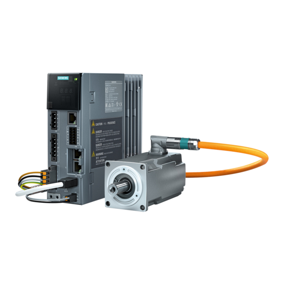
- Page 1 Operating Instructions SINAMICS/SIMOTICS Servo drive system SINAMICS S210 SINAMICS S210 converter SIMOTICS S-1FK2 servomotor Edition 01/2019 www.siemens.com/drives...
- Page 3 Preface Fundamental safety instructions Description SINAMICS/SIMOTICS Configuring SINAMICS S210 servo drive system Safety functions integrated in the drive Installing Operating Instructions Commissioning and diagnostics using the web server Series commissioning Diagnostics Service and maintenance Technical specifications Dimension drawings Decommissioning and...
- Page 4 Note the following: WARNING Siemens products may only be used for the applications described in the catalog and in the relevant technical documentation. If products and components from other manufacturers are used, these must be recommended or approved by Siemens. Proper transport, storage, installation, assembly, commissioning, operation and maintenance are required to ensure that the products operate safely and without any problems.
-
Page 5: Preface
These operating instructions are intended for persons who perform different tasks in the drive environment, e.g. for: ● Planning engineers ● Project engineers ● Machine manufacturers ● Commissioning engineers ● Electricians ● Installation personnel ● Service technician ● Warehouse personnel SINAMICS S210 servo drive system Operating Instructions, 01/2019, A5E41702836B AC... - Page 6 Siemens does not control the information on these websites and is also not responsible for the contents and information provided there. Use of these websites is at the risk of the person doing so.
- Page 7 Young. This product contains software (mailto:eay@cryptsoft.com) developed by Eric Young. Compliance with the General Data Protection Regulation Siemens respects the principles of data protection, in particular the data minimization rules (privacy by design). For this product, this means: The product does not process neither store any person-related data, only technical function data (e.g.
- Page 8 Preface SINAMICS S210 servo drive system Operating Instructions, 01/2019, A5E41702836B AC...
-
Page 9: Table Of Contents
Configuring the braking resistor .....................65 3.4.1 Calculating the braking energy....................66 3.4.2 Requirements placed on the external braking resistor ............67 3.4.3 Connecting an external braking resistor.................69 DC link coupling ........................70 Application examples ......................72 SINAMICS S210 servo drive system Operating Instructions, 01/2019, A5E41702836B AC... - Page 10 Acceptance tests – Basic Functions..................129 4.6.1.1 STO acceptance test......................129 4.6.1.2 Acceptance test SS1......................131 4.6.1.3 SBC acceptance test......................132 4.6.2 Acceptance tests Extended Functions .................132 Information pertaining to component replacements .............133 Functional safety ........................136 SINAMICS S210 servo drive system Operating Instructions, 01/2019, A5E41702836B AC...
- Page 11 6.2.1 Assigning the drive name.....................196 6.2.2 Adapting the direction of rotation of the motor ..............197 6.2.3 Performing One Button Tuning ....................198 6.2.4 Setting limits.........................201 6.2.5 Setting the brake control ......................202 SINAMICS S210 servo drive system Operating Instructions, 01/2019, A5E41702836B AC...
- Page 12 Status displays and operating elements on the converter ...........255 8.1.1 Status display via LEDs .......................256 Message classes in accordance with PROFIdrive ...............258 Alarms ..........................261 Faults ...........................262 Service and maintenance .........................263 Service and maintenance for the motor ................263 SINAMICS S210 servo drive system Operating Instructions, 01/2019, A5E41702836B AC...
- Page 13 Specific data of the converter with 3 AC line connection .............316 10.3 Technical data and properties of the connection system .............318 Dimension drawings ..........................321 11.1 Dimension drawings of motor....................321 11.2 Dimension drawings of converter..................327 SINAMICS S210 servo drive system Operating Instructions, 01/2019, A5E41702836B AC...
- Page 14 Directives, standards and certificates for the converter ............549 A.3.2 Directives, standards and certificates for the motor .............550 Certifications ........................553 Certificates for the secure data transfer ................554 A.5.1 Certificate standard configuration ..................555 SINAMICS S210 servo drive system Operating Instructions, 01/2019, A5E41702836B AC...
- Page 15 Table of contents A.5.2 Your own certificates......................560 List of abbreviations ......................561 Index.................................565 SINAMICS S210 servo drive system Operating Instructions, 01/2019, A5E41702836B AC...
- Page 16 Table of contents SINAMICS S210 servo drive system Operating Instructions, 01/2019, A5E41702836B AC...
-
Page 17: Fundamental Safety Instructions
● You must use an additional residual-current device (RCD) if a conductor-ground short circuit does not reach the short-circuit current required for the protective device to respond. The required short-circuit current can be too low, especially for TT supply systems. SINAMICS S210 servo drive system Operating Instructions, 01/2019, A5E41702836B AC... - Page 18 Hazardous voltages can be present at the enclosure or at exposed components on damaged motors or devices. ● Ensure compliance with the limit values specified in the technical data during transport, storage and operation. ● Do not use any damaged motors or devices. SINAMICS S210 servo drive system Operating Instructions, 01/2019, A5E41702836B AC...
- Page 19 ● Install built-in units in a suitable metal cabinet in such a way that personnel are protected against fire and smoke, or take other appropriate measures to protect personnel. ● Ensure that smoke can only escape via controlled and monitored paths. SINAMICS S210 servo drive system Operating Instructions, 01/2019, A5E41702836B AC...
- Page 20 ● If you come closer than around 2 m to such components, switch off any radios or mobile phones. ● Use the "SIEMENS Industry Online Support app" only on equipment that has already been switched off. SINAMICS S210 servo drive system...
- Page 21 SINAMICS S210 servo drive system Operating Instructions, 01/2019, A5E41702836B AC...
- Page 22 Inadequate cooling can cause the motor to overheat, resulting in death or severe injury as a result of smoke and fire. This can also result in increased failures and reduced service lives of motors. ● Comply with the specified cooling requirements for the motor. SINAMICS S210 servo drive system Operating Instructions, 01/2019, A5E41702836B AC...
- Page 23 ● Mount the motor so that it is not accessible in operation. Measures when maintenance is required: ● Allow the motor to cool down before starting any work. ● Use the appropriate personnel protection equipment, e.g. gloves. SINAMICS S210 servo drive system Operating Instructions, 01/2019, A5E41702836B AC...
-
Page 24: Equipment Damage Due To Electric Fields Or Electrostatic Discharge
– Wearing ESD shoes or ESD grounding straps in ESD areas with conductive flooring ● Only place electronic components, modules or devices on conductive surfaces (table with ESD surface, conductive ESD foam, ESD packaging, ESD transport container). SINAMICS S210 servo drive system Operating Instructions, 01/2019, A5E41702836B AC... -
Page 25: Warranty And Liability For Application Examples
As the user you yourself are responsible for ensuring that the products described are operated correctly. Application examples do not relieve you of your responsibility for safe handling when using, installing, operating and maintaining the equipment. SINAMICS S210 servo drive system Operating Instructions, 01/2019, A5E41702836B AC... -
Page 26: Industrial Security
Siemens’ products and solutions undergo continuous development to make them more secure. Siemens strongly recommends that product updates are applied as soon as they are available and that the latest product versions are used. Use of product versions that are no longer supported, and failure to apply the latest updates may increase customer’s exposure to cyber... - Page 27 ● Protect files stored on exchangeable storage media from malicious software by with suitable protection measures, e.g. virus scanners. ● Protect the drive against unauthorized changes by activating the "know-how protection" drive function. SINAMICS S210 servo drive system Operating Instructions, 01/2019, A5E41702836B AC...
-
Page 28: Residual Risks Of Power Drive Systems
6. Influence of network-connected communication systems, e.g. ripple-control transmitters or data communication via the network For more information about the residual risks of the drive system components, see the relevant sections in the technical user documentation. SINAMICS S210 servo drive system Operating Instructions, 01/2019, A5E41702836B AC... -
Page 29: Fundamental Safety Instructions For Safety Integrated
Emergency Stop is reset). An automatic start is permitted when a protective door is closed, for example. ● For the cases listed above, ensure that an automatic restart is absolutely not possible. SINAMICS S210 servo drive system Operating Instructions, 01/2019, A5E41702836B AC... - Page 30 In these cases, you must ensure that the causes of the messages are corrected immediately. Example: ● F13000 licensing is insufficient Purchase the license required for operation of the Extended Functions or activate a Trial License. SINAMICS S210 servo drive system Operating Instructions, 01/2019, A5E41702836B AC...
-
Page 31: Description
The motor is only approved for operation with a converter. Typical applications ● Robots and handling systems ● Packaging, plastics and textile machines ● Wood, glass, ceramics and stone working machines ● Printing machines SINAMICS S210 servo drive system Operating Instructions, 01/2019, A5E41702836B AC... -
Page 32: System Overview
(PLC). Connection to the controller is via PROFINET: Prefabricated MOTION-CONNECT cables in various lengths are available to simply connect the motor to the converter and to ensure safe and reliable operation. Figure 2-1 System SINAMICS S210 servo drive system Operating Instructions, 01/2019, A5E41702836B AC... - Page 33 OCC extension cable (optional) Controller, e.g. SIMATIC S7-1500 ⑧ Mounting flange for control cabinet X1: Connector for line cabling - option ⑯ bushing (optional) X3: Connector for DC link cabling - option SINAMICS S210 servo drive system Operating Instructions, 01/2019, A5E41702836B AC...
- Page 34 Description 2.1 System overview Figure 2-3 System components and accessories for converters with 3 AC line connection SINAMICS S210 servo drive system Operating Instructions, 01/2019, A5E41702836B AC...
-
Page 35: The Scope Of Supply For The System Components
● X1: Connector for line connection ● X4: Connector for external braking resistor (jumper for internal braking resistor is included) Note All connectors are designed so that they cannot be inadvertently interchanged. SINAMICS S210 servo drive system Operating Instructions, 01/2019, A5E41702836B AC... - Page 36 Details on the OCC MOTION-CONNECT cables can be found in the following Section: Connection cables between the motor and the converter (Page 336). Optional accessories The optional accessories are listed in the following Section: Accessories (Page 339). SINAMICS S210 servo drive system Operating Instructions, 01/2019, A5E41702836B AC...
-
Page 37: Motor
If the ambient temperature exceeds 40 °C (104 °F) or the installation altitude 1000 meters above sea level, you must reduce torque and power of the motor (derating). Information on derating can be found in Chapter: "Derating factors (Page 283)" SINAMICS S210 servo drive system Operating Instructions, 01/2019, A5E41702836B AC... - Page 38 The holding brake closes in the current-free state and locks the motor shaft at a standstill. When current flows, the holding brake opens and releases the motor shaft. SINAMICS S210 controls the holding brake without any additional devices. The holding brake is not a working brake for braking the rotating motor. Limited EMERGENCY STOP operation is permissible.
-
Page 39: Data On The Rating Plate
/ rpm rated Marking of encoder type Maximum speed / rpm Data of the holding brake Certifications Manufacturer's address Standard for all rotating electrical ma‐ chines Stall current Data matrix code SINAMICS S210 servo drive system Operating Instructions, 01/2019, A5E41702836B AC... -
Page 40: Converter
Safety functions integrated in the drive (Page 75) The Basic Functions are included in the scope of delivery of the converter. The Extended Functions require a license. Using functions that require a license (Page 248) SINAMICS S210 servo drive system Operating Instructions, 01/2019, A5E41702836B AC... - Page 41 The commissioning, diagnostics and data backup are performed using a PC or notebook (commissioning device) via the web server integrated in the converter - or using the Startdrive commissioning software. Commissioning and diagnostics using the web server (Page 177) SINAMICS S210 servo drive system Operating Instructions, 01/2019, A5E41702836B AC...
- Page 42 Note on disposal Date of manufacture The date of manufacture of the converter is coded, as shown below in the serial number. Figure 2-5 Date of manufacture (example April 2014) SINAMICS S210 servo drive system Operating Instructions, 01/2019, A5E41702836B AC...
- Page 43 SCCR: 65kA USE 60/75°C COPPER WIRES ONLY 2,1 kg REFER TO USER MANUAL LISTED IND.CONT.EQ. 65BA Siemens AG, Frauenauracher Str. 80, DE-91056 Erlangen Made in Germany Manufacturer Reference to the manual Function status and material number Certificates Product designation 10 Manufacturer's address...
- Page 44 3SL3210-5HE11-0UF0 1 Product designation PROFINET interface 2 Function release/version MAC address of the PROFINET interface 3 Service interface Article number 4 MAC address of the service interface Data matrix code SINAMICS S210 servo drive system Operating Instructions, 01/2019, A5E41702836B AC...
-
Page 45: Connection Systems
The OCC cables can be supplied in lengths by the decimeter. Extensions and cabinet bushings are available for the OCC cables. For additional information, see Chapter: "Technical data and properties of the connection system (Page 318)" SINAMICS S210 servo drive system Operating Instructions, 01/2019, A5E41702836B AC... -
Page 46: Motor-Converter Combinations
1 … 10 of the 6SL3210-5HE10- 6FX . 002-... article num‐ ber) …10-4UF0 …10-8UF0 …11-0UF0 …11-5UF0 …8QN04-... … 8QN08-... High Dynamic 1FK2102-0A 0.16 1FK2102-1A 0.32 1FK2103-2A 0.64 1FK2103-4A 1.27 1FK2104-4A 1.27 Compact SINAMICS S210 servo drive system Operating Instructions, 01/2019, A5E41702836B AC... - Page 47 11-0UF 11-5UF 12-0UF 13-5UF 15-0UF 17-0UF High Dynamic 1FK2104-4AF 1.27 1FK2104-5AF 2.39 1FK2104-6AF 3.18 1FK2105-4AF 1FK2105-6AF 1FK2106-3AF 1FK2106-4AF 1FK2106-6AF Compact 1FK2204-5AF 2.39 1FK2204-6AF 3.18 1FK2205-2AF 1FK2205-4AF 1FK2206-2AF 1FK2206-4AF 1FK2208-3AC 1FK2208-4AC SINAMICS S210 servo drive system Operating Instructions, 01/2019, A5E41702836B AC...
- Page 48 Article number ticle number) 6SL3210-5HE... 6FX . 002-... … … … … … … … … 8QN08- 8QN11- 10-4UF 10-8UF 11-0UF 11-5UF 12-0UF 13-5UF 15-0UF 17-0UF 1FK2208-5AC 1FK2210-3AC 1FK2210-4AC Available soon SINAMICS S210 servo drive system Operating Instructions, 01/2019, A5E41702836B AC...
-
Page 49: Configuring
● Connect the mounting plate to the control cabinet frame and PE bar and shield support through a large surface area to establish a good electrical connection. Permissible protective elements and the required control cabinet sizes: Protective devices (https://support.industry.siemens.com/cs/ww/en/view/109748999) SINAMICS S210 servo drive system Operating Instructions, 01/2019, A5E41702836B AC... -
Page 50: Cables
– Cable between the converter and motor – Cable between the converter and external braking resistor – Signal cables if they are routed next to cables with high levels of noise and interference SINAMICS S210 servo drive system Operating Instructions, 01/2019, A5E41702836B AC... - Page 51 ● Use shielded cables for the following connections: – Converter motor cable – Cable between the converter and braking resistor – Signal and data cables SINAMICS S210 servo drive system Operating Instructions, 01/2019, A5E41702836B AC...
-
Page 52: Electromechanical Components
– Solenoid valves ● Connect the surge voltage protection circuit directly at the coil. ● Use RC elements or varistors for AC-operated coils and freewheeling diodes or varistors for DC-operated coils. SINAMICS S210 servo drive system Operating Instructions, 01/2019, A5E41702836B AC... -
Page 53: Permissible Line Supplies And Connection Options
Destruction of the converter when operated without grounding screw The converter will be destroyed in operation if the grounding screw is removed for converters with 3 AC line connection. ● Do not remove the grounding screw. SINAMICS S210 servo drive system Operating Instructions, 01/2019, A5E41702836B AC... -
Page 54: Connecting Options For Converters With 1 Ac Line Connection
Connecting options for converters with 1 AC line connection Basic connection options You have the following options to supply the converter with an input voltage of 230 V. Figure 3-3 Connection options SINAMICS S210 servo drive system Operating Instructions, 01/2019, A5E41702836B AC... - Page 55 ● Cables for the line connection up to the terminal box 2.5 mm , dimensioned for I ≥ 18.5 A at 50 °C ● Cables for establishing the connection between the terminal box and the converter SINAMICS S210 servo drive system Operating Instructions, 01/2019, A5E41702836B AC...
- Page 56 ● Cables for the line connection up to the terminal box 2.5 mm , dimensioned for I ≥ 18.5 A at 50 °C ● Cables for establishing the connection between the terminal box and the converter SINAMICS S210 servo drive system Operating Instructions, 01/2019, A5E41702836B AC...
-
Page 57: Connecting Options For Converters With 3 Ac Line Connection
Connection options You can connect each converter individually via the standard terminals, or via the optional line cabling. Figure 3-6 Converter with 3 AC line connection without line cabling SINAMICS S210 servo drive system Operating Instructions, 01/2019, A5E41702836B AC... - Page 58 Cables for establishing the connection between the termi‐ 6 mm nal box and the converter Figure 3-7 Converter with 3 AC line connection with line cabling SINAMICS S210 servo drive system Operating Instructions, 01/2019, A5E41702836B AC...
- Page 59 16 mm Cables for establishing the connection between the terminal boxes and the converters and for the DC link coupling Connectors and cables for line and DC link cabling (Page 340) SINAMICS S210 servo drive system Operating Instructions, 01/2019, A5E41702836B AC...
-
Page 60: Configuring The Motor
- and specify the power supplies (SITOP devices, Control Supply Modules) Determine the connection system components Configure the drive line-up components Calculate the required cable cross sections for power supply and motor con‐ nections Inclusion of mandatory installation clearances SINAMICS S210 servo drive system Operating Instructions, 01/2019, A5E41702836B AC... -
Page 61: Clarify The Drive Type
The limiting characteristic curves describe the torque or power curve over the speed. The limiting characteristic curves take the limits of the motor into account on the basis of the DC- link voltage. The DC-link voltage is dependent on the line voltage. SINAMICS S210 servo drive system Operating Instructions, 01/2019, A5E41702836B AC... - Page 62 For duty cycles with constant ON duration, there are specific requirements for the torque characteristic curve as a function of the speed, for example: M = constant, M ~ n , M ~ n or P = constant. SINAMICS S210 servo drive system Operating Instructions, 01/2019, A5E41702836B AC...
- Page 63 Curve of the base load torque Figure 3-10 Motor selection for a duty cycle with constant switch-on duration 3. Select a motor that satisfies the requirements of S1 duty. ❒ SINAMICS S210 servo drive system Operating Instructions, 01/2019, A5E41702836B AC...
- Page 64 • + • • • • The motor speed is: • The effective torque is obtained as follows: ∑ • t Δ The average motor speed is calculated as follows: • SINAMICS S210 servo drive system Operating Instructions, 01/2019, A5E41702836B AC...
- Page 65 Effective torque ● Points from the traversing profile n_mean Mean speed Figure 3-12 Motor selection for duty cycle You have defined the characteristic motor values corresponding to the duty cycle. ❒ SINAMICS S210 servo drive system Operating Instructions, 01/2019, A5E41702836B AC...
- Page 66 ● Comply with the thermal limits of the motor. ● Configure the other properties of the motor through the available motor options. SINAMICS S210 servo drive system Operating Instructions, 01/2019, A5E41702836B AC...
-
Page 67: Configuring The Braking Resistor
Converter with 3 AC line connection 6SL3210-5HE10-4UF0 (0.4 kW) 6SL3210-5HE10-8UF0 (0.75 kW) 6SL3210-5HE11-0UF0 (1 kW) 6SL3210-5HE11-5UF0 (1.75 kW) 6SL3210-5HE12-0UF0 (2 kW) 6SL3210-5HE13-5UF0 (3.5 kW) 6SL3210-5HE15-0UF0 (5 kW) 6SL3210-5HE17-0UF0 (7 kW) SINAMICS S210 servo drive system Operating Instructions, 01/2019, A5E41702836B AC... -
Page 68: Calculating The Braking Energy
The braking energy that can be absorbed by the integrated braking resistor (1680 J) is higher than the actual braking energy (22.03 J). In this case, therefore, no external braking resistor is required. SINAMICS S210 servo drive system Operating Instructions, 01/2019, A5E41702836B AC... -
Page 69: Requirements Placed On The External Braking Resistor
Converter with 3 AC line connection 6SL3210-5HE10-4UF0 (0.4 kW) 6SL3210-5HE10-8UF0 (0.75 kW) 6SL3210-5HE11-0UF0 (1 kW) 6SL3210-5HE11-5UF0 (1.75 kW) 6SL3210-5HE12-0UF0 (2 kW) 1000 6SL3210-5HE13-5UF0 (3.5 kW) 1750 6SL3210-5HE15-0UF0 (5 kW) 2500 6SL3210-5HE17-0UF0 (7 kW) 3250 SINAMICS S210 servo drive system Operating Instructions, 01/2019, A5E41702836B AC... - Page 70 2) For thermal reasons, it is not permissible that the continuous braking power of 400 W is exceeded. Note Braking resistor with temperature monitoring Use only a braking resistor with temperature monitoring. SINAMICS S210 servo drive system Operating Instructions, 01/2019, A5E41702836B AC...
-
Page 71: Connecting An External Braking Resistor
Activate the digital input DI 4 "Temperature monitoring of the external braking resistor". The converter switches the motor off as soon as the external braking resistor is too hot or when no external braking resistor is connected (wire break). SINAMICS S210 servo drive system Operating Instructions, 01/2019, A5E41702836B AC... -
Page 72: Dc Link Coupling
2. Establishing the line supply and DC link cabling: Use the connectors and cables that are described in the following section: Connectors and cables for line and DC link cabling (Page 340) SINAMICS S210 servo drive system Operating Instructions, 01/2019, A5E41702836B AC... - Page 73 Otherwise, the above mentioned points apply. When connected to 3 AC 200 V … 240 V line supplies, also refer to the following Section: Connecting options for converters with 3 AC line connection (Page 55) SINAMICS S210 servo drive system Operating Instructions, 01/2019, A5E41702836B AC...
-
Page 74: Application Examples
The result list is updated every time a filter setting is specified. You reset individual filters by clicking the X to the right of the filter. You reset all filters simultaneously by clicking the "Reset filters" button. SINAMICS S210 servo drive system Operating Instructions, 01/2019, A5E41702836B AC... -
Page 75: Establishing Communication Of The Converter With The Controller
● Telegram 750 PROFIsafe telegrams ● Telegram 30 (recommended for Safety Integrated Basic Functions) ● Telegram 901 (recommended for Safety Integrated Extended Functions) For further information about telegrams Communication telegrams (Page 539) SINAMICS S210 servo drive system Operating Instructions, 01/2019, A5E41702836B AC... -
Page 76: Functions That Require A License
Using functions that require a license (Page 248) Note Refer to your ordering documentation (e.g. catalogs) for information on basic functions and functions subject to license. The licenses are saved to folder "KEYS" on the memory card. SINAMICS S210 servo drive system Operating Instructions, 01/2019, A5E41702836B AC... -
Page 77: Safety Functions Integrated In The Drive
PFH values of other components used for this safety function. ● The PFH values of the SINAMICS S210 can be found at: PFH values (https://support.industry.siemens.com/cs/ww/en/view/76254308) ● The PFH values of all Safety components from Siemens are available in the "Safety Evaluation Tool"; see: Safety Evaluation Tool (http://www.industry.siemens.com/topics/global/en/safety- integrated/machine-safety/safety-evaluation-tool/Pages/default.aspx) -
Page 78: Basic Functions
Details regarding the settings can be obtained in the following sections: Configuring safety functions (Page 118) Establishing communication of the converter with the controller (Page 73) The Safety Integrated Functions are executed with a safety monitoring cycle of 4 ms. SINAMICS S210 servo drive system Operating Instructions, 01/2019, A5E41702836B AC... -
Page 79: Safe Torque Off (Sto)
Details regarding the distinction between Emergency Off and Emergency Stop are provided in the following section: What is the difference between the Emergency Off and Emergency Stop functions? (Page 548) SINAMICS S210 servo drive system Operating Instructions, 01/2019, A5E41702836B AC... - Page 80 ● The Safety error is acknowledged with selection/deselection of the STO function. Additional information is provided in Chapter "Faults (Page 262)". Selecting/deselecting "Safe Torque Off" If "Safe Torque Off" is selected, the motor holding brake is closed (if connected and configured). SINAMICS S210 servo drive system Operating Instructions, 01/2019, A5E41702836B AC...
- Page 81 1. The Safety requirement "Close motor holding brake" is canceled. 2. The possibly active F01611 fault or STO is withdrawn. 3. In addition, reset the messages in the fault buffer using the general acknowledgment mechanism. SINAMICS S210 servo drive system Operating Instructions, 01/2019, A5E41702836B AC...
-
Page 82: Safe Stop 1 (Ss1, Time-Controlled)
When SS1-t is selected, the motor speed is reduced along the OFF3 ramp for the duration of the selected delay time. After the delay time expires, the drive activates the STO function (independent of the actual speed). Note Braking at the OFF3 ramp is not monitored! SINAMICS S210 servo drive system Operating Instructions, 01/2019, A5E41702836B AC... - Page 83 ● The "SS1_active" status is signaled in the status bit of the PROFIsafe telegram. ● This value can be applied in the higher-level controller. ● When STO becomes active, the "SS1_active" status is also signaled in the status bit of the PROFIsafe telegram. SINAMICS S210 servo drive system Operating Instructions, 01/2019, A5E41702836B AC...
- Page 84 ● SS1 and STO are deactivated by the drive with (manual or automatic program-controlled) deselection. ● The drive is again "ready for switching on". ● You restart the drive with the ON/OFF1 signal. SINAMICS S210 servo drive system Operating Instructions, 01/2019, A5E41702836B AC...
- Page 85 ● SS1 delay time = 0 → STO (stop category 0 according to EN 60204-1) ● SS1 delay time ≠ 0 → SS1 (stop category 1 according to EN 60204-1) SINAMICS S210 servo drive system Operating Instructions, 01/2019, A5E41702836B AC...
-
Page 86: Safe Brake Control (Sbc)
SBC is not able to identify as to whether a holding brake is mechanically worn or is a defective. As a consequence, observe the maximum permissible number of emergency braking operations for the motor holding brake being used. SINAMICS S210 servo drive system Operating Instructions, 01/2019, A5E41702836B AC... - Page 87 The drive adopts a controlling function for the "Safe Brake Control" function and ensures the following behavior: ● If the drive detects a fault or failure of the brake, it deactivates the brake current. ● The brake closes and a safe state is reached. SINAMICS S210 servo drive system Operating Instructions, 01/2019, A5E41702836B AC...
- Page 88 EN 61800‑5‑2:2007, Appendix D. ● During commissioning, test the brake using the Safety Integrated Extended Function "Safe Brake Test (SBT)": Additional information is provided in Chapter "Safe Brake Test (SBT) (Page 110)". SINAMICS S210 servo drive system Operating Instructions, 01/2019, A5E41702836B AC...
-
Page 89: Extended Functions
Details regarding the settings can be obtained in the following sections: Configuring safety functions (Page 118) Establishing communication of the converter with the controller (Page 73) The Safety Integrated Functions are executed with a safety monitoring cycle of 4 ms. SINAMICS S210 servo drive system Operating Instructions, 01/2019, A5E41702836B AC... -
Page 90: Safe Torque Off (Sto)
● The load torque does not reduce the motor to a standstill through friction within a sufficiently short time. ● Coasting down of the drive (STO) will pose risks to safety. SINAMICS S210 servo drive system Operating Instructions, 01/2019, A5E41702836B AC... -
Page 91: Safe Stop 1 With Acceleration Monitoring (Ss1-A)
● STO and SS1 are deactivated by the drive with (manual or automatic program-controlled) deselection. ● The drive is again "ready for switching on". ● You restart the drive with a positive signal edge at ON/OFF1. SINAMICS S210 servo drive system Operating Instructions, 01/2019, A5E41702836B AC... - Page 92 ● You can utilize this status in the higher-level controller. ● If STO is active, the "STO_active" status is also signaled in the corresponding status bit of the PROFIsafe telegram. SINAMICS S210 servo drive system Operating Instructions, 01/2019, A5E41702836B AC...
-
Page 93: Safe Stop 1 With Braking Ramp Monitoring (Ss1-R)
● STO is triggered by the drive when the STO shutdown speed is reached or when the SS1 delay time has elapsed. ● The motor coasts down to a standstill. ● The drive safely prevents a restart of the motor with the pulse inhibit. SINAMICS S210 servo drive system Operating Instructions, 01/2019, A5E41702836B AC... - Page 94 ● You can utilize this status in the higher-level controller. ● If STO is active, the drive also signals the "STO_active" status in the corresponding status bit of the PROFIsafe telegram. SINAMICS S210 servo drive system Operating Instructions, 01/2019, A5E41702836B AC...
-
Page 95: Safe Stop 2 (Ss2)
If a higher-level motion controller is used, Safety function SS2E or SOS should be applied. Reason: With Safety function SS2-r/SS2-a, SINAMICS S210 brakes autonomously along the OFF3 ramp. The motion controller detects a deviation between target value and actual value and shifts the drive to pulse cancellation. -
Page 96: Ss2 With Acceleration Monitoring (Ss2-A)
● The acceleration monitoring SAM is set with the speed tolerance (p9548). ● SINAMICS S210 monitors the change in speed between 2 safety monitoring cycles to ensure that it does not exceed the speed tolerance (p9548). The monitoring is deactivated when the SAM speed limit is fallen below (p9568). - Page 97 ● The "SS2_active" status is signaled in the status bit of the PROFIsafe telegram. ● You can utilize this status in the higher-level controller. ● If SOS is active, the drive also signals "SOS_active" in the corresponding status bit of the PROFIsafe telegram. SINAMICS S210 servo drive system Operating Instructions, 01/2019, A5E41702836B AC...
-
Page 98: Ss2 With Braking Ramp Monitoring (Ss2-R)
● Standstill of the motor safely monitored with Safety function SOS. The motor remains in control mode. ● SS2 and SOS are deactivated with (manual or automatic program-controlled) deselection. ● You can immediately continue traversing the axis from the standstill position. SINAMICS S210 servo drive system Operating Instructions, 01/2019, A5E41702836B AC... -
Page 99: Safe Operating Stop (Sos)
The drive must be braked to standstill within this delay time, e.g. by the controller. Applications SOS is suitable for the following applications: ● Machine parts must be safely monitored that they actually are at a standstill. ● A holding torque is required. SINAMICS S210 servo drive system Operating Instructions, 01/2019, A5E41702836B AC... - Page 100 ● Monitoring of the position window is concluded with "Deselect SOS" via the control bit of the selected PROFIsafe telegram. ● The drive may be operated freely. Contrary to SS1 and SS2, SOS does not automatically brake the drive. SINAMICS S210 servo drive system Operating Instructions, 01/2019, A5E41702836B AC...
-
Page 101: Safely-Limited Speed (Sls)
SLS is suitable for machines susceptible to hazardous situations if a speed is exceeded and wherever work must be performed directly on a machine, for example: ● During operation ● In setup mode ● For maintenance work SINAMICS S210 servo drive system Operating Instructions, 01/2019, A5E41702836B AC... -
Page 102: Sls With A Speed Level
● The drive ends monitoring of the SLS limit value with deselection of SLS via the control bit of the selected PROFIsafe telegram. ● The drive may be operated freely. SINAMICS S210 servo drive system Operating Instructions, 01/2019, A5E41702836B AC... -
Page 103: Sls With Switchover Of Speed Levels
● You can continue traversing the axis immediately with greater setpoints (e.g. changing over to "Automatic" mode). Settings ● SLS (level 1) is selected via the control bit of the selected PROFIsafe telegram. SINAMICS S210 servo drive system Operating Instructions, 01/2019, A5E41702836B AC... - Page 104 ● The drive ends monitoring of the SLS limit value with deselection of SLS (level 2) via the control bit of the selected PROFIsafe telegram. ● The drive may be operated freely. SINAMICS S210 servo drive system Operating Instructions, 01/2019, A5E41702836B AC...
-
Page 105: Sls With Variable Speed Limit Value
SLS limit value using your control system (F‑CPU). ● If an incorrect SLS limit value is transferred, the drive responds with the stop response parameterized in p9563 for speed level 1 and Safety alarm A01711. SINAMICS S210 servo drive system Operating Instructions, 01/2019, A5E41702836B AC... -
Page 106: Additional Functional Features
ESR reaction is only realized if, as SLS response, a stop reaction with delayed pulse cancellation when the bus fails has been parameterized (p9563[0...3] ≥ 10). SINAMICS S210 servo drive system Operating Instructions, 01/2019, A5E41702836B AC... -
Page 107: Safe Speed Monitor (Ssm)
● If the speed falls below the speed limit, the "Speed below limit value" signal is set. ● If the speed is greater than the limit, the "Speed below limit value" is not set. SINAMICS S210 servo drive system Operating Instructions, 01/2019, A5E41702836B AC... -
Page 108: Safe Direction (Sdi)
Safe Direction (SDI) The drive with active SDI function monitors the motor's direction of rotation. If the motor rotates in the impermissible direction, the drive stops the motor as quickly as possible. SINAMICS S210 servo drive system Operating Instructions, 01/2019, A5E41702836B AC... - Page 109 ● The drive ends monitoring of the direction of rotation with "Deselect SDI" via the control bit of the selected PROFIsafe telegram. ● You can traverse the axis immediately in both directions of rotation. SINAMICS S210 servo drive system Operating Instructions, 01/2019, A5E41702836B AC...
-
Page 110: Safely-Limited Acceleration (Sla)
"The SLA function prevents the motor from exceeding the de‐ fined acceleration limit." Applications SLA is suitable for machines for which the permissible acceleration may not be exceeded, for example in setup mode. SINAMICS S210 servo drive system Operating Instructions, 01/2019, A5E41702836B AC... - Page 111 ● You can traverse the axis immediately in both directions of rotation. Settings ● Define the maximum permissible acceleration with the acceleration limit (p9578). ● Select SLA via a control bit of the PROFIsafe telegram. SINAMICS S210 servo drive system Operating Instructions, 01/2019, A5E41702836B AC...
-
Page 112: Safe Brake Test (Sbt)
SBT is suitable for implementing a "safe brake" in conjunction with SBC. This allows errors or wear to be detected in the brake mechanics. Automatic testing of the braking effect reduces maintenance costs and increases safety and availability of the machine or plant. Flow diagram SINAMICS S210 servo drive system Operating Instructions, 01/2019, A5E41702836B AC... - Page 113 Decide upon the following before initiating the brake test sequence: – Brake to be tested S_STW3B.2 – Positive or negative direction of the test torque S_STW3B.3 – Brake test sequence 1 or 2 S_STW3B.4 SINAMICS S210 servo drive system Operating Instructions, 01/2019, A5E41702836B AC...
- Page 114 4. Start brake test Start the brake test sequence in S_STW3B.1. 5. Exit brake test – Withdraw the "Start brake test" in S_STW3B.1. – Withdraw "Select brake test" in S_STW3B.0. SINAMICS S210 servo drive system Operating Instructions, 01/2019, A5E41702836B AC...
-
Page 115: Safe Acceleration Monitor (Sam)
STO. Monitoring using SAM is activated for SS1 and SS2, and ends if STO or SOS take over the monitoring. Figure 4-1 Example: SS1 with SAM SINAMICS S210 servo drive system Operating Instructions, 01/2019, A5E41702836B AC... - Page 116 OFF3 ramp. However, the size of this cannot be calculated. Responses to braking ramp violations ● Safety alarm A01706 (SI Motion: SAM/SBR limit exceeded) ● Stopping the drive with STO SINAMICS S210 servo drive system Operating Instructions, 01/2019, A5E41702836B AC...
-
Page 117: Safe Brake Ramp (Sbr)
– As soon as the SS2 delay time (p9552) has elapsed. Following deactivation of the SBR monitoring, depending on the function used, the drive activates the specific subsequent function: Function used Subsequent function SINAMICS S210 servo drive system Operating Instructions, 01/2019, A5E41702836B AC... - Page 118 If the ramp- down time OFF3 (p1135) is set to several minutes, you must extend the delay time to several seconds in order to avoid any unwanted faults when selecting SS1. SINAMICS S210 servo drive system Operating Instructions, 01/2019, A5E41702836B AC...
- Page 119 The longer the monitoring time settings, the more tolerant the monitoring. Responses to braking ramp violations ● Safety alarm A01706 (SI Motion: SAM/SBR limit exceeded) ● Stopping the drive with STO SINAMICS S210 servo drive system Operating Instructions, 01/2019, A5E41702836B AC...
-
Page 120: Configuring Safety Functions
Safety Integrated Extended Functions. Detailed information about the telegrams and control word and status word assignments can be found in Sections Supplementary telegrams (Page 541) and Standard telegrams (Page 539). SINAMICS S210 servo drive system Operating Instructions, 01/2019, A5E41702836B AC... -
Page 121: Responses To Safety Faults And Alarms
In this way, you can stop the machine optimally adapted to the specific situation. Figure 4-3 Overview of the responses More detailed information about the various stop responses is provided in the description of the specific Safety Integrated Function. SINAMICS S210 servo drive system Operating Instructions, 01/2019, A5E41702836B AC... -
Page 122: Discrepancy At The Inputs Of The F-Di
"Table 8-2 Status explanation of the RDY LED (Page 256)". ● The drive sets the error bit of the safety functions (= internal event). Communication telegrams (Page 539) and Bit assignments of the process data (Page 542) SINAMICS S210 servo drive system Operating Instructions, 01/2019, A5E41702836B AC... - Page 123 - After "(permissible) discrepancy time" + "transition time F01611 to STO" expires (p9650 + p9658). – Please note: For active discrepancy errors F01611/F30311 (internal event), the motor can still be operated as long as STO is not yet active. SINAMICS S210 servo drive system Operating Instructions, 01/2019, A5E41702836B AC...
-
Page 124: Acknowledging Alarms And/Or Faults And Switching On The Motor Again
Extended Safety, can only be acknowledged in a safety-related way using STO if p9507.0 = 1 is set. (extended message acknowledgment to default value). See also Communication telegrams (Page 539) Bit assignments of the process data (Page 542) SINAMICS S210 servo drive system Operating Instructions, 01/2019, A5E41702836B AC... -
Page 125: Response Times
Selection until braking is initiated 12 ms + 2 ms + t_E 16 ms + 2 ms + t_E The following applies for t_E (debounce time of the digital input being used): SINAMICS S210 servo drive system Operating Instructions, 01/2019, A5E41702836B AC... - Page 126 Safety functions integrated in the drive 4.5 Response times p9651 t_E = 8 ms p9651 ≠ 0 t_E = p9651 + 5 ms p9652: SI SS1 delay time p9651: SI STO/SBC/SS1 debounce time SINAMICS S210 servo drive system Operating Instructions, 01/2019, A5E41702836B AC...
-
Page 127: Control Of The Safety Integrated Basic Functions Via Profisafe
SINAMICS module; t_K can be determined as follows: For isochronous communication t_K = To (determine To from the bus configuration on the control side) For non-isochronous communication t_K = 4 ms p9652: SI SS1 delay time SINAMICS S210 servo drive system Operating Instructions, 01/2019, A5E41702836B AC... -
Page 128: Response Times Of Safety Integrated Extended Functions
= To (determine To from the bus configuration on the control side) For non-isochronous t_K = 4 ms communication Safety monitoring cycle Extended Functions t_EF = 4 ms Safety monitoring cycle Basic Functions t_BF = 4 ms SINAMICS S210 servo drive system Operating Instructions, 01/2019, A5E41702836B AC... -
Page 129: Acceptance - Completion Of Commissioning
Documentation The following must be documented for the drive: ● Result of the acceptance tests ● Settings of the integrated drive safety functions This documentation must be countersigned. SINAMICS S210 servo drive system Operating Instructions, 01/2019, A5E41702836B AC... - Page 130 If you replaced the drive, you have to conduct an acceptance test for it. Note When you replace the drive, an error message appears. Acknowledge this error message, e.g. by switching off and on. SINAMICS S210 servo drive system Operating Instructions, 01/2019, A5E41702836B AC...
-
Page 131: Acceptance Tests - Basic Functions
Use the following procedure for the acceptance test of the Basic Function STO: Switch on motor 1. Enter a speed setpoint ≠ 0. 2. Switch on the motor (ON command). 3. Check that the motor rotates as required. SINAMICS S210 servo drive system Operating Instructions, 01/2019, A5E41702836B AC... - Page 132 – STO is not active (r9734.0 = 0). – The drive signals neither faults nor alarms of the safety functions (r0945[0…7], r2122[0… 7]). – Check that the motor rotates as required. SINAMICS S210 servo drive system Operating Instructions, 01/2019, A5E41702836B AC...
-
Page 133: Acceptance Test Ss1
– SS1 is not active (r9734.1 = 0). – The drive signals neither faults nor alarms of the safety functions (r0945[0…7], r2122[0… 7]). – Check that the motor rotates as required. SINAMICS S210 servo drive system Operating Instructions, 01/2019, A5E41702836B AC... -
Page 134: Sbc Acceptance Test
As of version 15.1 of the commissioning tool Startdrive, a wizard is available for this purpose to guide you step by step through the acceptance process. SINAMICS S210 servo drive system Operating Instructions, 01/2019, A5E41702836B AC... -
Page 135: Information Pertaining To Component Replacements
- It is not permissible that the firmware update is active on the drive object. - Copy from RAM to ROM by setting p0977 = 1. If the modified data is not saved, then the drive re-issues the fault at the next power on. SINAMICS S210 servo drive system Operating Instructions, 01/2019, A5E41702836B AC... - Page 136 – The converter data (hardware/software version) should be added to the acceptance protocol, the changed checksum and time stamp should be documented and countersigned. SINAMICS S210 servo drive system Operating Instructions, 01/2019, A5E41702836B AC...
- Page 137 Test the encoder parameterization (a trace recording is not required) ● The converter data (hardware/software version) should be added to the acceptance protocol, the changed checksum and time stamp should be documented and countersigned. SINAMICS S210 servo drive system Operating Instructions, 01/2019, A5E41702836B AC...
-
Page 138: Functional Safety
This is expressed in the standards using specific classification. In IEC/EN 61508, IEC/EN 62061 "Safety Integrity Level" (SIL) and EN ISO 13849‑1 "Category" and "Performance Level" (PL). SINAMICS S210 servo drive system Operating Instructions, 01/2019, A5E41702836B AC... -
Page 139: Machinery Directive
Manufacturers and suppliers of PDS(SR) can prove to users (e.g. integrators of control systems, developers of machines and plants etc.) the safety-relevant performance of their equipment by implementing the specifications stipulated in standard IEC 61800‑5‑2. SINAMICS S210 servo drive system Operating Instructions, 01/2019, A5E41702836B AC... - Page 140 Safety functions integrated in the drive 4.9 Machinery Directive SINAMICS S210 servo drive system Operating Instructions, 01/2019, A5E41702836B AC...
-
Page 141: Installing
● Ensure that no temperature-sensitive parts come into contact with hot surfaces. SINAMICS S210 servo drive system Operating Instructions, 01/2019, A5E41702836B AC... -
Page 142: Installing The Motor
Have the mounting surfaces (e.g. flange, shaft) on the customer machine and on the motor been cleaned? Are the mounting surfaces free of corrosion? Do the mounting dimensions (e.g. shaft diameter, shaft length, true run) on the customer machine meet the specification? SINAMICS S210 servo drive system Operating Instructions, 01/2019, A5E41702836B AC... -
Page 143: Mounting Instructions For The Motor
1FK2☐04 6 (d2 = 11) 8 Nm 1FK2105 1FK2205 8 (d2 = 15) 20 Nm 1FK2☐06 1FK2☐08 10 (d2 = 18) 35 Nm 1FK2☐10 12 (d2 = 20) 60 Nm SINAMICS S210 servo drive system Operating Instructions, 01/2019, A5E41702836B AC... -
Page 144: Attaching The Output Elements
● If necessary, completely balance the motor together with the output elements according to ISO 1940. Note Motors with feather key are half-key balanced. The motors have been balanced with half a feather key. SINAMICS S210 servo drive system Operating Instructions, 01/2019, A5E41702836B AC... - Page 145 Installing 5.2 Installing the motor The motor dimensions can be found in Chapter: "Dimension drawings (Page 321)" SINAMICS S210 servo drive system Operating Instructions, 01/2019, A5E41702836B AC...
-
Page 146: Installing The Converter
● Install the converter vertically with the flap for the LED display facing upwards. Figure 5-2 Mounting position of the converter ● Maintain the minimum clearances to other components. ● Use the recommended fastening elements and comply with the specified torques. SINAMICS S210 servo drive system Operating Instructions, 01/2019, A5E41702836B AC... - Page 147 Clearances to cabinet panels and other components Leave a minimum 100 mm clearance to other devices at the top and bottom. A lateral clearance between multiple SINAMICS S210 converters is not mandatory. Observe a lateral clearance of at least 10 mm to other devices.
-
Page 148: Dimensions And Drilling Dimensions
2 x M5 / 4 Nm 55 mm 170 mm 170 mm 1.2 kg 2 x M5 / 4 Nm 74.5 mm 170 mm 197.4 mm 1.9 kg 3 x M5 / 4 Nm SINAMICS S210 servo drive system Operating Instructions, 01/2019, A5E41702836B AC... - Page 149 70 mm 322 mm 280 mm 223.3 mm 3.2 kg 4 x M5 / 4 Nm 105 mm 322 mm 280 mm 223.3 mm 4 x M5 / 4 Nm SINAMICS S210 servo drive system Operating Instructions, 01/2019, A5E41702836B AC...
-
Page 150: Connecting The Converter And The Motor
The data is applicable for the complete cable length of the motors, whose associated converters are coupled with one another through the DC link. The maximum cable length for a motor is 50 m. SINAMICS S210 servo drive system Operating Instructions, 01/2019, A5E41702836B AC... - Page 151 X4 (R1, DCP) 10 m line connection Service interface X127 10 m Digital inputs X130 30 m Connection to the control system via PROFINET X150 P1 100 m X150 P2 SINAMICS S210 servo drive system Operating Instructions, 01/2019, A5E41702836B AC...
-
Page 152: Connecting A Motion-Connect Cable At The Motor
OCC cable. ● Use the prefabricated MOTION-CONNECT OCC cables from SIEMENS. This reduces the installation time and costs, and increases the operational reliability of the drive. - Page 153 A maximum of 10 rotations are permitted so as not to impair the degree of protection of the motor. Table 5-6 Rotational range of the connector Motor Angle α Angle α' Connector Drawing size 1FK2☐02 261° 45° 1FK2☐03 SINAMICS S210 servo drive system Operating Instructions, 01/2019, A5E41702836B AC...
- Page 154 1. Ensure that the union nut of the SPEED-CONNECT connector is rotated to the end stop in the direction of the "open" arrow. 2. Align the SPEED-CONNECT connector so that the triangles on the top of the connectors are opposite one another. SINAMICS S210 servo drive system Operating Instructions, 01/2019, A5E41702836B AC...
- Page 155 The triangles on the top of the connectors must be opposite one another. 2. Withdraw the connector. Note Pull out the connector at the connector itself, do not pull on the cable. You have disconnected the SPEED-CONNECT connection. ❒ SINAMICS S210 servo drive system Operating Instructions, 01/2019, A5E41702836B AC...
- Page 156 If you are operating the motor in environments in which moisture can arise follow the installation instructions below. Figure 5-9 Permissible and impermissible cable routing when connecting in a damp environment SINAMICS S210 servo drive system Operating Instructions, 01/2019, A5E41702836B AC...
-
Page 157: Connecting The Converter
For converters, frame sizes FSB and FSC with 3 AC line connection, the shield plate is integrated in the converter itself. For the other converters, the shield plate is included in the accessories pack of the converter. SINAMICS S210 servo drive system Operating Instructions, 01/2019, A5E41702836B AC... - Page 158 ● Connect the shield at both ends of the cable. Use the converter shield plate to connect the shield at the converter. Siemens recommends connecting the shield using the shield clamp that is provided with the prefabricated OCC cable for the motor connection. See the following diagram: ●...
- Page 159 Encoder connector X100 is included with the OCC cable. You require Ethernet cables with RJ45 connectors to connect service interface X127 - as well as for PROFINET ports X150 P1 and X150 P2. SINAMICS S210 servo drive system Operating Instructions, 01/2019, A5E41702836B AC...
- Page 160 You must separately order the connectors for line supply cabling X1 and for DC link cabling X3 as required. Connectors and cables for line and DC link cabling (Page 340) SINAMICS S210 servo drive system Operating Instructions, 01/2019, A5E41702836B AC...
-
Page 161: Converters With 1 Ac Line Connection
Connecting other devices (motors, encoders) can destroy the converter or the connected device. ● Only connect 1FK2 motors to the converter. ● Use only MOTION-CONNECT cables from Siemens or cables that you have fabricated yourself with the correct pin assignment. Connecting the motor cable to the converter Connect conductors U, V, W of the MOTION-CONNECT cable to connector X2 of the converter as shown below. - Page 162 Installing 5.4 Connecting the converter and the motor Insert the Siemens IX connector in the X100 socket connector as shown in the diagram. Figure 5-12 X100 - encoder connection Connecting the motor holding brake The cables for the motor holding brake are part of the MOTION-CONNECT cable from the motor to the converter.
-
Page 163: Connecting The Converter To The Line Supply
X1 - line connection 1 AC Permissible conductor cross-sections for single-conductor connection or for connecting flexible cables with end sleeves: ● 0.2 mm … 2.5 mm2 ● AWG: 26 … 12 SINAMICS S210 servo drive system Operating Instructions, 01/2019, A5E41702836B AC... -
Page 164: Connecting An External Braking Resistor
X1 - connection for an external braking resistor Permissible conductor cross-sections for single-conductor connection or for connecting flexible cables with end sleeves: ● 0.2 mm … 2.5 mm ● AWG: 26 … 12 SINAMICS S210 servo drive system Operating Instructions, 01/2019, A5E41702836B AC... -
Page 165: Converter With 3 Ac Line Connection
Connecting other devices (motors, encoders) can destroy the converter or the connected device. ● Only connect 1FK2 motors to the converter. ● Use only MOTION-CONNECT cables from Siemens or cables that you have fabricated yourself with the correct pin assignment. Connecting the motor cable to the converter Connect conductors U, V, W of the MOTION-CONNECT cable to connector X2 of the converter as shown below. - Page 166 The cables and the connector for the encoder connection are part of the MOTION-CONNECT cable from the motor to the converter. Insert the Siemens IX connector in the X100 socket connector as shown in the diagram. Figure 5-17 X100 - encoder connection...
-
Page 167: Connecting The Converter To The Line Supply
X1 - line connection 3 AC - standard Permissible conductor cross-sections for single-conductor connection or for connecting flexible cables with or without end sleeves: ● 0.75 mm … 6 mm ● AWG: 18 … 10 SINAMICS S210 servo drive system Operating Instructions, 01/2019, A5E41702836B AC... - Page 168 The permissible cables for the line cabling as well as the installation instructions are provided in the following Section: Connecting the line cabling and DC link coupling (Page 168) Figure 5-20 X1 - line connection 3 AC - cabling SINAMICS S210 servo drive system Operating Instructions, 01/2019, A5E41702836B AC...
-
Page 169: Dc Link Cabling
Connecting the line cabling and DC link coupling (Page 168) The preconditions for the DC link coupling are described in the following Section: DC link coupling (Page 70) Figure 5-21 X3 - connecting the DC link cabling SINAMICS S210 servo drive system Operating Instructions, 01/2019, A5E41702836B AC... -
Page 170: Connecting The Line Cabling And Dc Link Coupling
3. For the line cabling, close and seal the connector of the last converter using an end cap - and for the DC link coupling of the first and last converter using end caps. SINAMICS S210 servo drive system Operating Instructions, 01/2019, A5E41702836B AC... - Page 171 Establishing the line cabling - example for the DC link Note The cables for the line and DC link coupling may only be used once. Further, comply with the notes provided in the documentation supplied with the contactors. SINAMICS S210 servo drive system Operating Instructions, 01/2019, A5E41702836B AC...
-
Page 172: Connecting An External Braking Resistor
X4 - connection for an external braking resistor Permissible conductor cross-sections for single-conductor connection or for connecting flexible cables with or without end sleeves: ● 0.75 mm … 6 mm ● AWG: 18 … 10 SINAMICS S210 servo drive system Operating Instructions, 01/2019, A5E41702836B AC... -
Page 173: Additional Connections At 1 Ac / 3 Ac Converters
When you use the temperature monitoring function, the converter shuts down the motor if the external braking resistor temperature becomes too high. The terminals are spring-loaded terminals Permissible cable length: 30 m Figure 5-25 X130 - connector for digital inputs SINAMICS S210 servo drive system Operating Instructions, 01/2019, A5E41702836B AC... - Page 174 The three "L+" terminals are designed as power supply for external sensors. They are short- circuit proof and provide a max. of 50 mA per sensor. A sensor short-circuit interrupts the power supply for all three sensors. SINAMICS S210 servo drive system Operating Instructions, 01/2019, A5E41702836B AC...
-
Page 175: Connecting Service Interface And Profinet
Reserved Sending data - Reserved Reserved Permissible cable length for PROFINET (terminals X150 P1 and X150 P2): 100 m Permissible cable length for the service interface (terminal X127): 10 m SINAMICS S210 servo drive system Operating Instructions, 01/2019, A5E41702836B AC... -
Page 176: Connection Example
Installing 5.4 Connecting the converter and the motor 5.4.7 Connection example Connection example for converters with 1 AC line connection SINAMICS S210 servo drive system Operating Instructions, 01/2019, A5E41702836B AC... - Page 177 Installing 5.4 Connecting the converter and the motor Connection example for converters with 3 AC line connection SINAMICS S210 servo drive system Operating Instructions, 01/2019, A5E41702836B AC...
-
Page 178: Connection Example Of The Failsafe Digital Input
Installing 5.4 Connecting the converter and the motor 5.4.8 Connection example of the Failsafe Digital Input SINAMICS S210 servo drive system Operating Instructions, 01/2019, A5E41702836B AC... -
Page 179: Commissioning And Diagnostics Using The Web Server
● from the PC via <F5> ● from the smart phone or tablet via SINAMICS S210 servo drive system Operating Instructions, 01/2019, A5E41702836B AC... -
Page 180: Fundamentals
As an alternative to access via X127, you can also access the web server via PROFINET interface X150. Access via PROFINET interface Configuring the IP connection (Page 243) The IP addresses of the service and PROFINET interfaces must not be in the same subnet. SINAMICS S210 servo drive system Operating Instructions, 01/2019, A5E41702836B AC... -
Page 181: Users And Access Rights
A password is always required for access as administrator. ● SINAMICS The "SINAMICS" user has restricted access rights, see the following table. Per default, a password is not assigned for the SINAMICS user. SINAMICS S210 servo drive system Operating Instructions, 01/2019, A5E41702836B AC... - Page 182 ● Configure IP connection ● Configure system time Save permanently (copy RAM to ROM) Write None Call support information Read Read This function is not displayed for a "SINAMICS" user. SINAMICS S210 servo drive system Operating Instructions, 01/2019, A5E41702836B AC...
-
Page 183: Dialog Screen Forms In The Web Server
In some cases, you must make the parameter settings or read out values which can only be found in the parameter list of the converter. Details on this are provided in Section: Adapting parameters (Page 206) SINAMICS S210 servo drive system Operating Instructions, 01/2019, A5E41702836B AC... -
Page 184: Changing Parameter Values
Display parameters are for information purposes only and cannot be changed. ① Display parameters with this icon have several indices or bit arrays Figure 6-2 Example of the representation of a display parameter SINAMICS S210 servo drive system Operating Instructions, 01/2019, A5E41702836B AC... -
Page 185: Logging On For The First Time And Assigning An Administrator Password
Proceed as follows to assign an administrator password: 1. Switch the converter on. 2. Connect the commissioning device to the service interface (X127) using a LAN cable. SINAMICS S210 servo drive system Operating Instructions, 01/2019, A5E41702836B AC... - Page 186 5. Repeat the password in the "Confirm password" field. If the input is not identical in both fields, the "OK" button is not enabled. SINAMICS S210 servo drive system Operating Instructions, 01/2019, A5E41702836B AC...
- Page 187 6. Confirm the password that you entered with "OK". 7. The display changes to the Login screen form. Log in there with the administrator password. Figure 6-4 Login screen (Page 186) SINAMICS S210 servo drive system Operating Instructions, 01/2019, A5E41702836B AC...
-
Page 188: Login/Logout
1. Enter the IP address for the converter in the entry line of your browser (default IP address: 169.254.11.22). The password prompt appears in the browser. Figure 6-4 Login screen 2. Enter the name of the user (Administrator or SINAMICS) in the "User name" field. SINAMICS S210 servo drive system Operating Instructions, 01/2019, A5E41702836B AC... - Page 189 Any changes that you made are not lost when automatically logging out. After logging in again, you have the option of opening a memory dialog via Saving data in a non-volatile fashion (Page 193) SINAMICS S210 servo drive system Operating Instructions, 01/2019, A5E41702836B AC...
-
Page 190: Start Page Of The Web Server
Navigation-dependent main window ④ Action bar (from left to right): Support information / Call control panel / Save retentively (RAM to ROM) Figure 6-6 Basic structure of the web server SINAMICS S210 servo drive system Operating Instructions, 01/2019, A5E41702836B AC... -
Page 191: Navigating In The Web Server
(drop- down menus). This also allows easy navigation in small displays (smartphone). ① Main menu as icon ② Main menu in text format ③ Submenus of the active main menu SINAMICS S210 servo drive system Operating Instructions, 01/2019, A5E41702836B AC... -
Page 192: Calling Support Information
6.1 Fundamentals 6.1.7.2 Calling Support information You can call the Support addresses for the SINAMICS S210 via the footer of the Web server. 1. Click "Support" in the footer of the Web server. The following information is displayed: Figure 6-7 Support addresses Open or copy the required support addresses via the links. -
Page 193: Using The Control Panel
1. To call the control panel, click the "Control panel" button in the footer of the web server. The control panel is displayed in monitoring mode. 2. Click the "Assume control" button. SINAMICS S210 servo drive system Operating Instructions, 01/2019, A5E41702836B AC... - Page 194 7. To close the control panel again, click the "Control panel" button again in the footer of the web server or the X at the top right in the "Control panel" dialog. SINAMICS S210 servo drive system Operating Instructions, 01/2019, A5E41702836B AC...
-
Page 195: Saving Data In A Non-Volatile Fashion
This allows you to easily replace the converter in a spare part scenario. Replacing the converter with memory card (Page 274) SINAMICS S210 servo drive system Operating Instructions, 01/2019, A5E41702836B AC... -
Page 196: Commissioning Using The Web Server
● The converter is connected to the commissioning device via the service interface (X127). ● You have assigned the administrator password. Logging on for the first time and assigning an administrator password (Page 183) SINAMICS S210 servo drive system Operating Instructions, 01/2019, A5E41702836B AC... - Page 197 ⑨ Backing up parameters (Page 238) Note: You can also save the settings after each commissioning step. We recommend that you make a backup before starting to commission Safety Integrated. SINAMICS S210 servo drive system Operating Instructions, 01/2019, A5E41702836B AC...
-
Page 198: Assigning The Drive Name
The assigned drive name is displayed in the status bar of the web browser, on the overview page for the converter data and on the tab of the browser window. 4. Click to save the data permanently. You have assigned the drive name. ❒ SINAMICS S210 servo drive system Operating Instructions, 01/2019, A5E41702836B AC... -
Page 199: Adapting The Direction Of Rotation Of The Motor
This means that you must enter a setpoint for clockwise rotation ( ) at the control panel, in order that the motor rotates counter-clockwise ( SINAMICS S210 servo drive system Operating Instructions, 01/2019, A5E41702836B AC... -
Page 200: Performing One Button Tuning
1. Select "Commissioning > Tuning" in the navigation. Figure 6-12 View before performing the One Button Tuning 2. Click "Take Control". Confirm the safety prompt. The master control is indicated by a broken orange bar. SINAMICS S210 servo drive system Operating Instructions, 01/2019, A5E41702836B AC... - Page 201 (e.g. 360 °) without the mechanical system being damaged. Note If you enter a negative angle, then the motor moves in the opposite direction. Generally, longer traversing distances result in better optimization results. SINAMICS S210 servo drive system Operating Instructions, 01/2019, A5E41702836B AC...
- Page 202 8. Confirm the confirmation prompt with "Confirm". The color bar is no longer displayed. 9. Click to save the data permanently. This means that you have executed One Button Tuning. ❒ SINAMICS S210 servo drive system Operating Instructions, 01/2019, A5E41702836B AC...
-
Page 203: Setting Limits
2. Enter the maximum speed in the input field of the same name. 3. Enter the two torque limit values. – "Torque limit, upper" – "Torque limit, lower" 4. Click to save the data permanently. SINAMICS S210 servo drive system Operating Instructions, 01/2019, A5E41702836B AC... -
Page 204: Setting The Brake Control
The values in this screen form serve more as a check. It may only be necessary to adapt the values for suspended /vertical axes. Electronic weight counterbalance for a vertical axis (Page 210) SINAMICS S210 servo drive system Operating Instructions, 01/2019, A5E41702836B AC... - Page 205 2. If required, adapt the brake control values in the "Value" column: – "Standstill detection speed threshold" – "Standstill detection monitoring time" – "Pulse cancellation delay time" 3. Click to save the data permanently. SINAMICS S210 servo drive system Operating Instructions, 01/2019, A5E41702836B AC...
-
Page 206: Configuring Digital Inputs
If you use these digital inputs, you have to set a telegram in the controller that transfers the values, e.g. the PROFIdrive telegram 105. The converter also has an input (DI 4) to monitor the temperature of an optional external braking resistor. Connection example (Page 174) SINAMICS S210 servo drive system Operating Instructions, 01/2019, A5E41702836B AC... - Page 207 Safety commissioning and can make the appropriate settings there. "Commissioning Safety Integrated (Page 211)" – "Digital input 4 (X130/DI 4)": Temperature monitoring of ext. braking resistor 3. Click to save the data permanently. SINAMICS S210 servo drive system Operating Instructions, 01/2019, A5E41702836B AC...
-
Page 208: Adapting Parameters
The following sections describe how you can adapt the parameter list to address your specific requirements. You will find a detailed description of the individual parameters and parameter types in the following Section: Parameters (Page 349) SINAMICS S210 servo drive system Operating Instructions, 01/2019, A5E41702836B AC... -
Page 209: Configuring The Parameter List
You can create an individual list using "My Group", see "Grouping parameters" Figure 6-18 Parameter list: Advanced view This advanced list view is only temporary. The next time the web server is called, the simple view is displayed again. SINAMICS S210 servo drive system Operating Instructions, 01/2019, A5E41702836B AC... - Page 210 "My group" column to assign the selected parameters to your personal group. 1. In the "My group" column, activate all checkboxes of the parameters that you want to take into your group. 2. Click to save the data permanently. SINAMICS S210 servo drive system Operating Instructions, 01/2019, A5E41702836B AC...
-
Page 211: Changing The Parameter Value
AND operation). The filters can be set in any order. Note Collapsing the filter bar The filter bar is opened per default. To collapse the filter bar, click the arrow next to "Search and Filters". SINAMICS S210 servo drive system Operating Instructions, 01/2019, A5E41702836B AC... -
Page 212: Electronic Weight Counterbalance For A Vertical Axis
Thus, when the load is lifted, a supplementary torque can be specified that is different from the supplementary torque for movement without a load. The supplementary telegram 750 must be configured in the PLC. Supplementary telegrams (Page 541) SINAMICS S210 servo drive system Operating Instructions, 01/2019, A5E41702836B AC... -
Page 213: Commissioning Safety Integrated
● Install the drive so that it is in compliance with EMC regulations according to the specifications in Section: EMC-compliant installation of a machine or system (Page 47) SINAMICS S210 servo drive system Operating Instructions, 01/2019, A5E41702836B AC... -
Page 214: Overview Of Safety Integrated Commissioning
④ Selection to control the Safety functions ⑤ Safety password ⑥ Selects the Safety functions ⑦ Activation of the read-only mode (prevents inadvertent changes) Figure 6-21 Overview: Safety commissioning Wizard SINAMICS S210 servo drive system Operating Instructions, 01/2019, A5E41702836B AC... - Page 215 This function is available to you – both as administrator or if you are logged into SINAMICS. Displaying the Safety commissioning view The individual commissioning steps are displayed in the header of the "Safety Commissioning" screen form. SINAMICS S210 servo drive system Operating Instructions, 01/2019, A5E41702836B AC...
- Page 216 ● The commissioning steps marked with a red pen require entries. Basic information on the safety functions Detailed information on the safety functions used can be found in the following Chapter: Safety functions integrated in the drive (Page 75) SINAMICS S210 servo drive system Operating Instructions, 01/2019, A5E41702836B AC...
-
Page 217: Commissioning Safety Integrated
Functions) (Page 221) (Page 222) ● Control via PROFIsafe and onboard terminals (Page 222) ● Test stop (forced checking procedure) (Page 223) ● Finalizing commissioning (Page 225) ● Safety password (Page 226) SINAMICS S210 servo drive system Operating Instructions, 01/2019, A5E41702836B AC... -
Page 218: Function Selection
– Basic Functions – Extended Functions, these functions require a license Functions that require a license (Page 74) 2. In addition to the preselected functions, select the additional functions that you require. SINAMICS S210 servo drive system Operating Instructions, 01/2019, A5E41702836B AC... - Page 219 7. To start the configuration of the individual Safety commissioning steps, click "Start" in the footer of the screen form. See also Commissioning Extended Functions (Page 219) SINAMICS S210 servo drive system Operating Instructions, 01/2019, A5E41702836B AC...
-
Page 220: Commissioning Basic Functions
2. Using the drop-down list "SI SS1 drive based braking response" you determine whether SS1 should be operated with OFF3 or with an external stop. 3. If you have selected "Basic Functions": – Click "Continue". – The "Control" commissioning step is activated. SINAMICS S210 servo drive system Operating Instructions, 01/2019, A5E41702836B AC... -
Page 221: Commissioning Extended Functions
6.3 Commissioning Safety Integrated 6.3.2.4 Commissioning Extended Functions Parameterizing Extended Functions All functions which you have selected are displayed in the lower section of the screen form: Figure 6-25 Parameterizing Extended Functions SINAMICS S210 servo drive system Operating Instructions, 01/2019, A5E41702836B AC... - Page 222 3. Parameterize all of the selected functions and the "Actual value sensing / mechanical system" of your application. 4. When you have parameterized all functions, click on "Continue". The "Control" commissioning step is activated. SINAMICS S210 servo drive system Operating Instructions, 01/2019, A5E41702836B AC...
-
Page 223: Commissioning The Control
● Current sourcing/sourcing F-DO of external devices ● Self-monitoring sensors (OSSD) ● Non-self-monitoring sensors (e.g. emergency stop button) The existing modules of external devices operate with different test pulses for the on/off test. SINAMICS S210 servo drive system Operating Instructions, 01/2019, A5E41702836B AC... - Page 224 The "Test stop" commissioning step is activated. Control via PROFIsafe and onboard terminals With this selection, you combine both possibilities: ● Control via PROFIsafe (Page 221) ● Controlling via onboard terminals (only Basic Functions) (Page 221) SINAMICS S210 servo drive system Operating Instructions, 01/2019, A5E41702836B AC...
-
Page 225: Test Stop (Forced Checking Procedure)
1. To change the time interval, click in the "Timer test stop" field. 2. Set the time interval for the timer. Confirm with "OK". The remaining time up to the test stop is determined automatically and displayed. SINAMICS S210 servo drive system Operating Instructions, 01/2019, A5E41702836B AC... -
Page 226: Acceptance Test Mode
(even in the "SS2 active" state), the setpoint is enabled again by the acceptance test mode after deceleration and transition to SOS to allow SINAMICS S210 servo drive system Operating Instructions, 01/2019, A5E41702836B AC... -
Page 227: Finalizing Commissioning
– The drive adopts the settings of Safety commissioning. – A restart is performed. Following the restart, commissioning of the drive-integrated Safety functions is concluded. The browser displays the home page of the web server again. SINAMICS S210 servo drive system Operating Instructions, 01/2019, A5E41702836B AC... -
Page 228: Safety Password
If you have not assigned a password, any user can make changes to the settings of the drive- integrated safety functions by selecting "Safety Integrated / Commissioning". We therefore recommend that you always assign a password. SINAMICS S210 servo drive system Operating Instructions, 01/2019, A5E41702836B AC... -
Page 229: Checking Existing Safety Settings In The Read-Only Mode
If one of the drive-integrated safety functions is enabled (p9601 ≠ 0), then check the performed settings in read-only mode. This allows you to run through the complete Safety commissioning step-by-step without being able to perform changes. SINAMICS S210 servo drive system Operating Instructions, 01/2019, A5E41702836B AC... - Page 230 The individual commissioning steps are displayed in the header of the "Safety Commissioning" screen form. 2. Click the "Continue" button each time and check the values which you have set during Safety commissioning. SINAMICS S210 servo drive system Operating Instructions, 01/2019, A5E41702836B AC...
-
Page 231: Changing Safety Settings
1. Select "Safety Integrated > Commissioning" in the navigation. If you have set a Safety Integrated password, you must enter the password in order to access the Safety settings: Figure 6-33 Safety password SINAMICS S210 servo drive system Operating Instructions, 01/2019, A5E41702836B AC... -
Page 232: Safety Diagnostics
Safety diagnostics The most important information on the Safety settings and the states of the converter are displayed using the Safety diagnostics. 1. Select "Safety > Safety Diagnostics" in the navigation: SINAMICS S210 servo drive system Operating Instructions, 01/2019, A5E41702836B AC... - Page 233 – Enable drive-integrated functions Hardware-specific changes are recorded in the checksum r9781[1]: – Hardware-dependent CRC of motion monitoring ● "Acceptance test mode" For further information, see Chapter "Acceptance test mode (Page 224)". SINAMICS S210 servo drive system Operating Instructions, 01/2019, A5E41702836B AC...
-
Page 234: Diagnostic Functions
The "Diagnostics - Messages" view appears with a message list. Further information about S210 messages can be found in Chapter "Faults and alarms (Page 419)". Figure 6-34 Message list Explanation of the icons: Alarm Fault OK (acknowledged fault) SINAMICS S210 servo drive system Operating Instructions, 01/2019, A5E41702836B AC... -
Page 235: Filtering Messages
To reset all filter settings in the message list, proceed as follows: Click "Reset all filters" at the top right in the filter bar. The message list then displays the unfiltered view of the messages again. SINAMICS S210 servo drive system Operating Instructions, 01/2019, A5E41702836B AC... -
Page 236: Display Drive Status
Figure 6-36 Example, drive status The settings are not saved. The window is displayed in the basic setting if you log out and then log in again. SINAMICS S210 servo drive system Operating Instructions, 01/2019, A5E41702836B AC... -
Page 237: Displaying Communication Settings
● The standard telegram – Table with process data for the transfer direction "controller > converter" – Table with process data for the transfer direction "converter > controller" Figure 6-37 Communication settings SINAMICS S210 servo drive system Operating Instructions, 01/2019, A5E41702836B AC... - Page 238 The values are displayed in hexadecimal format in the default setting. You can switch the display of individual values between binary and hex format by clicking on the button to the right of the value. SINAMICS S210 servo drive system Operating Instructions, 01/2019, A5E41702836B AC...
-
Page 239: Backup And Restore
Backup and restore Using the following screen form, select the functions for backing up and restoring. Select "Backup and Restore" in the navigation. Figure 6-38 Backing up and restoring data SINAMICS S210 servo drive system Operating Instructions, 01/2019, A5E41702836B AC... -
Page 240: Backing Up Parameters
Note Checking and editing externally saved parameters The data are saved in a format that cannot be edited – further, they cannot be checked or modified. SINAMICS S210 servo drive system Operating Instructions, 01/2019, A5E41702836B AC... -
Page 241: Restoring Externally Backed-Up Parameter Settings
You have reset the converter to the factory settings and carried out the basic motor commissioning. ❒ Additional options for restoring the factory settings is provided in the following Section: Reset converter/password - restore the state when originally delivered (Page 270) SINAMICS S210 servo drive system Operating Instructions, 01/2019, A5E41702836B AC... -
Page 242: System Settings In The Web Server
Settings 6.6.1.1 Setting or changing user accounts For SINAMICS S210, both user accounts - "SINAMICS" and "Administrator" - are permanently defined, and cannot be changed by users. You can make the following settings in the user accounts: ● Changing the Administrator password ●... - Page 243 1. Select "System > Settings" in the navigation. 2. Select the "User Accounts" tab. 3. Activate the "Enable SINAMICS user" option. 4. Click "Define password..." at the "SINAMICS" user. A password dialog opens. SINAMICS S210 servo drive system Operating Instructions, 01/2019, A5E41702836B AC...
- Page 244 4. If you want to delete the password of the "SINAMICS" user, click "Delete password...". A prompt appears. Enter the old password and click "Delete". 5. Click to save the data permanently. You have changed/deleted the password for the "SINAMICS" user. ❒ SINAMICS S210 servo drive system Operating Instructions, 01/2019, A5E41702836B AC...
-
Page 245: Configuring The Ip Connection
Procedure 1. Select "System > Settings" in the navigation. 2. Select the "IP Connections and Addresses" tab. Figure 6-40 IP connections 3. Activate the desired connection options. SINAMICS S210 servo drive system Operating Instructions, 01/2019, A5E41702836B AC... - Page 246 To secure an HTTPS connection, it requires security certificates for the encryption of the access. Detailed information on working with these security certificates can be found in Chapter "Certificates for the secure data transfer (Page 554)". SINAMICS S210 servo drive system Operating Instructions, 01/2019, A5E41702836B AC...
-
Page 247: Configuring The System Time
4. Select the time zone (for Central Europe UTC+01:00) – only possible if NTP time synchronization has been activated. 5. Click "Apply Settings" to save the changes in the RAM of the device. 6. Click to save the data permanently. SINAMICS S210 servo drive system Operating Instructions, 01/2019, A5E41702836B AC... -
Page 248: Updating The Firmware Via The Web Server
● Do not disconnect the motor from the converter. LEDs are flashing synchronously: Converter waits until the power supply is switched off and switched on again after a firmware update. SINAMICS S210 servo drive system Operating Instructions, 01/2019, A5E41702836B AC... - Page 249 Remedy: Switch the component off and on again. 6. Check whether the new version is installed. The firmware version of the converter is displayed on the home page of the web server under the converter. SINAMICS S210 servo drive system Operating Instructions, 01/2019, A5E41702836B AC...
-
Page 250: Using Functions That Require A License
Trial License Mode. Details are provided in the following section. System reactions if there is a not a sufficient license A license that is not completely sufficient is displayed as follows: SINAMICS S210 servo drive system Operating Instructions, 01/2019, A5E41702836B AC... - Page 251 – Displayed when the RDY-LED flashes red with a frequency of 2 Hz. – Display using the fault display with F18 ● Via the web server – Fault F13000, "Licensing is insufficient" – System > Licenses SINAMICS S210 servo drive system Operating Instructions, 01/2019, A5E41702836B AC...
- Page 252 To be able to switch on the drive again, you must either activate the functions that require a license - or you must enter a valid license key. SINAMICS S210 servo drive system Operating Instructions, 01/2019, A5E41702836B AC...
- Page 253 4. Click on "Activate" to activate the license key that has just been entered. The dialog closes. The new license key becomes active the next time that the system runs- SINAMICS S210 servo drive system Operating Instructions, 01/2019, A5E41702836B AC...
- Page 254 Commissioning and diagnostics using the web server 6.6 System settings in the web server SINAMICS S210 servo drive system Operating Instructions, 01/2019, A5E41702836B AC...
-
Page 255: Series Commissioning
This not only saves the settings in a non-volatile fashion in the converter – but also to the memory card. 4. Switch off the converter and remove the memory card from the converter. 5. Insert the memory card into the next - switched off - converter. SINAMICS S210 servo drive system Operating Instructions, 01/2019, A5E41702836B AC... - Page 256 Repeat steps 4 ... 6 for all converters to which you want to transfer these settings. With this you have carried out a series commissioning for several converters via the web server. ❒ SINAMICS S210 servo drive system Operating Instructions, 01/2019, A5E41702836B AC...
-
Page 257: Diagnostics
You can acknowledge the faults whose cause has been corrected with the OK button. ① LED display ② Three-digit display ③ OK button Display and operating elements on the converter SINAMICS S210 servo drive system Operating Instructions, 01/2019, A5E41702836B AC... -
Page 258: Status Display Via Leds
● Check the converter settings/configuration. ● Activate the required license Firmware update is active Converter waits until the power supply is switched off and switched on again after a firmware update SINAMICS S210 servo drive system Operating Instructions, 01/2019, A5E41702836B AC... - Page 259 Remedy: Make sure that the bus cables are connected and are not damaged. Bus error, possible causes: ● Incorrect configuration in the PLC (the same supplementary telegram has been set twice?) SINAMICS S210 servo drive system Operating Instructions, 01/2019, A5E41702836B AC...
-
Page 260: Message Classes In Accordance With Profidrive
9007 Motor overload The motor was operated outside the permissible limits (temperature, current, torque…). ● Check the load cycles and set limits. ● Check the ambient temperature / motor cooling. SINAMICS S210 servo drive system Operating Instructions, 01/2019, A5E41702836B AC... - Page 261 Application / technology function faulted The application / technological function has exceeded a (set) limit (position, velocity, torque…). ● Identify and check the relevant limit. ● Check the setpoint specification of the higher-level controller. SINAMICS S210 servo drive system Operating Instructions, 01/2019, A5E41702836B AC...
- Page 262 ● Determine the precise cause of the fault using the commissioning tool. "Channel Error Type" of the PROFINET channel diagnostics. When channel diagnostics is activated, then the fault texts are indicated in the PLC. SINAMICS S210 servo drive system Operating Instructions, 01/2019, A5E41702836B AC...
-
Page 263: Alarms
– In the Web server via the "Diagnostics - Messages" view Alarm code or alarm value describe the cause of the alarm. Reference You can find additional information on alarms in Chapter "Overview of faults and alarms (Page 419)". SINAMICS S210 servo drive system Operating Instructions, 01/2019, A5E41702836B AC... -
Page 264: Faults
In the list of faults, you will find the information on limitations when acknowledging at the corresponding fault codes. Reference You can find additional information on faults in Chapter "Overview of faults and alarms (Page 419)". SINAMICS S210 servo drive system Operating Instructions, 01/2019, A5E41702836B AC... -
Page 265: Service And Maintenance
Interruption of a phase in the supply cable / Check the frequency converter and supply cables, measure the winding motor winding resistances and insulation resistances, repair after consultation with man‐ ufacturer SINAMICS S210 servo drive system Operating Instructions, 01/2019, A5E41702836B AC... - Page 266 Check coupled machine Fault originating from the gearbox Adjust/repair gearbox If the fault still cannot be resolved after taking the measures stated above, please contact the manufacturer or the Siemens Service Center. SINAMICS S210 servo drive system Operating Instructions, 01/2019, A5E41702836B AC...
-
Page 267: Replacing The Motor Bearings
Premature bearing and motor replacement Harsh operating conditions, e.g. continuous operation at n , high vibration/shock loads, frequent reversing duty reduce the bearing or motor replacement interval by up to 50 %. SINAMICS S210 servo drive system Operating Instructions, 01/2019, A5E41702836B AC... -
Page 268: Replacing The Motor
– Release the motor mounting screws. – Remove the motor. – Mount and install the new motor. More detailed information is provided in Chapter: Installing the motor (Page 140) 3. Switch the converter on. SINAMICS S210 servo drive system Operating Instructions, 01/2019, A5E41702836B AC... - Page 269 Switch the converter off and on again. 3. Commission the converter. – Commissioning using the web server (Page 194), – Series commissioning (Page 253) 4. Save the settings powerfail-proof via You have replaced the motor. ❒ SINAMICS S210 servo drive system Operating Instructions, 01/2019, A5E41702836B AC...
-
Page 270: Service And Maintenance For The Converter
Procedure Proceed as follows to update the firmware using the memory card: 1. Switch off the converter. 2. Insert the SD card into the converter and switch on the converter. SINAMICS S210 servo drive system Operating Instructions, 01/2019, A5E41702836B AC... - Page 271 Remedy: Switch the component off and on again. 6. Check whether the new version is installed. The firmware version of the converter is displayed on the home page of the web server under the converter. SINAMICS S210 servo drive system Operating Instructions, 01/2019, A5E41702836B AC...
-
Page 272: Reset Converter/Password - Restore The State When Originally Delivered
If you have forgotten the administrator password, then you cannot restore the factory settings of the converter via the web server. You must reset the converter with a memory card. SINAMICS S210 servo drive system Operating Instructions, 01/2019, A5E41702836B AC... - Page 273 2. Clear the converter IP address. 3. Establish a connection with the PROFINET interface (X150). 4. Clear the PROFINET communication settings. You have now cleared all the converter communication settings. ❒ SINAMICS S210 servo drive system Operating Instructions, 01/2019, A5E41702836B AC...
- Page 274 If you wish to operate the converter again in the machine, then you must first commission the converter. ● Commissioning using the web server (Page 194) ● Series commissioning (Page 253) SINAMICS S210 servo drive system Operating Instructions, 01/2019, A5E41702836B AC...
-
Page 275: Replacing Fans - Only For Converters With 3 Ac Line Connection
● Check the voltage at the converter connections before you carry out any installation work. 3. Remove the fan as shown in the diagram. SINAMICS S210 servo drive system Operating Instructions, 01/2019, A5E41702836B AC... -
Page 276: Replacing The Converter In A Spare Part Scenario
4. Insert the memory card into the converter. 5. Switch the converter on. The converter possibly upgrades/downgrades the firmware and must be switched off and switched on again. You have now replaced the converter. ❒ SINAMICS S210 servo drive system Operating Instructions, 01/2019, A5E41702836B AC... - Page 277 When it runs up, the converter takes the settings from the card, and after it has run up commissioning has been completed. Save the settings in the web server in a non-volatile fashion using You have now replaced the converter. ❒ SINAMICS S210 servo drive system Operating Instructions, 01/2019, A5E41702836B AC...
-
Page 278: Replacing The Converter Without Memory Card
2. Release all of the connections at the converter, replace the converter and re-establish the connections. Installing the converter (Page 144) Connecting the converter (Page 155) 3. Switch the converter on. 4. Assign the administrator password. 5. Log in as administrator. SINAMICS S210 servo drive system Operating Instructions, 01/2019, A5E41702836B AC... - Page 279 When it runs up, the converter takes the settings from the data backup, and after it runs up, commissioning is completed. Save the settings in the web server in a non-volatile fashion via You have now replaced the converter. ❒ SINAMICS S210 servo drive system Operating Instructions, 01/2019, A5E41702836B AC...
- Page 280 Service and maintenance 9.2 Service and maintenance for the converter SINAMICS S210 servo drive system Operating Instructions, 01/2019, A5E41702836B AC...
-
Page 281: Technical Specifications
Encoder systems, built-in with DRIVE- ● AS22DQC, absolute encoder singleturn 22 bit (code letter: S) CLiQ interface ● AM22DQC, absolute encoder 22 bit + 12 bit multiturn (code letter: M) SINAMICS S210 servo drive system Operating Instructions, 01/2019, A5E41702836B AC... -
Page 282: Permissible Environmental Conditions For The Motor
● Six months for the above-mentioned conditions. ● Special preservation measures are required for storage periods of 6 months up to a maximum of two years. Additional information Calling Support information (Page 190) SINAMICS S210 servo drive system Operating Instructions, 01/2019, A5E41702836B AC... - Page 283 The limit value of 89 kPa covers applications at altitudes up to 1000 m. Conditions in mines are not considered. Operation in a vacuum is not permissible because of the low dielectric strength and poor heat dissipation. SINAMICS S210 servo drive system Operating Instructions, 01/2019, A5E41702836B AC...
-
Page 284: Cooling
"Motor overtemperature". The thermal motor model requires the ambient temperature to be entered at the converter. ● To do this, select parameter p0613 at the converter. SINAMICS S210 servo drive system Operating Instructions, 01/2019, A5E41702836B AC... -
Page 285: Derating Factors
Configure the motor in the required degree of protection. Degrees of protection available for the 1FK2 1FK2 motors are available with IP64 or IP65 degree of protection. The degree of protection is specified on the rating plate. SINAMICS S210 servo drive system Operating Instructions, 01/2019, A5E41702836B AC... - Page 286 With degree of protection IP65, it is not permissible for liquid to collect in the flange. The service life of the radial shaft sealing ring is approximately 25000 operating hours. For additional information, see Chapter: "Shaft extension (Page 286)" SINAMICS S210 servo drive system Operating Instructions, 01/2019, A5E41702836B AC...
-
Page 287: Balancing
To measure the vibration velocity, the measuring equipment must fulfill the requirements of ISO 2954. The vibration acceleration is evaluated in the frequency range of 10 Hz to 2000 Hz. The maximum peak in the time range is considered. SINAMICS S210 servo drive system Operating Instructions, 01/2019, A5E41702836B AC... -
Page 288: Shaft Extension
38 × 80 10 × 8 × 70 The optional 11 mm x 23 mm shaft extension is only available without a keyway and without a shaft sealing ring (IP65). SINAMICS S210 servo drive system Operating Instructions, 01/2019, A5E41702836B AC... -
Page 289: Radial Eccentricity, Concentricity And Axial Eccentricity
Concentricity and axial eccentricity tolerance of the flange surface to the shaft axis (referred to the centering diameter of the mounting flange) Motor Standard (Normal class) 1FK2☐02 1FK2☐03 0.08 mm 1FK2☐04 1FK2☐05 1FK2☐06 1FK2☐08 0.1 mm 1FK2☐10 SINAMICS S210 servo drive system Operating Instructions, 01/2019, A5E41702836B AC... -
Page 290: Axial And Radial Forces
Permissible radial forces As a result of the bearing arrangement, 1FK2 is designed for aligned forces. Forces such as these occur for belt drives, for example. SINAMICS S210 servo drive system Operating Instructions, 01/2019, A5E41702836B AC... - Page 291 The following diagrams indicate the maximum permissible radial force for the corresponding motor frame size. It depends on the force application point and the average speed for a nominal bearing service life (L10h) of 25000 h. Radial force diagram 1FK2x02 SINAMICS S210 servo drive system Operating Instructions, 01/2019, A5E41702836B AC...
- Page 292 25000 h. Radial force diagram 1FK2x03 Figure 10-6 Maximum permissible radial force at a distance x from the shaft shoulder for a nominal bearing lifetime of 25000 h. SINAMICS S210 servo drive system Operating Instructions, 01/2019, A5E41702836B AC...
- Page 293 Radial force diagram 1FK2x04 Figure 10-7 Maximum permissible radial force at a distance x from the shaft shoulder for a nominal bearing lifetime of 25000 h. Radial force diagram 1FK2105 SINAMICS S210 servo drive system Operating Instructions, 01/2019, A5E41702836B AC...
- Page 294 25000 h. Radial force diagram 1FK2205 Figure 10-9 Maximum permissible radial force at a distance x from the shaft shoulder for a nominal bearing lifetime of 25000 h. SINAMICS S210 servo drive system Operating Instructions, 01/2019, A5E41702836B AC...
- Page 295 Radial force diagram 1FK2x06 Figure 10-10 Maximum permissible radial force at a distance x from the shaft shoulder for a nominal bearing lifetime of 25000 h. Radial force diagram 1FK2208 SINAMICS S210 servo drive system Operating Instructions, 01/2019, A5E41702836B AC...
-
Page 296: Available Encoders
Identification in the article number Resolution 4,194,304 = 22 bit 4,194,304 = 22 bit Absolute position Yes, one revolution Yes, 4096 revolutions (12 bits) Angular error ± 100" ± 100" SINAMICS S210 servo drive system Operating Instructions, 01/2019, A5E41702836B AC... -
Page 297: Brake Data
The holding brakes of the 1FK2 have a torsional backlash of less than 1.5°. The following table lists additional technical data regarding the holding brakes for operation with a SINAMICS S210 converter from firmware version 5.2. Motor type Holding torque Dyn. -
Page 298: Technical Data And Characteristics 1Fk2 High Dynamic
Load moment of inertia of the mounting part on the motor with brake (kgm load 182.4 Constant for calculating the circular frequency and SI units 10.1.13 Technical data and characteristics 1FK2 High Dynamic 10.1.13.1 1FK2102-0AG Technical data (in SINAMICS S210 system) Symbol Unit Value Static torque 0.16 Stall current 0.75... - Page 299 Technical specifications 10.1 Technical data and properties of the motor Rated torque 0.16 rated Rated current 0.75 rated Rated power 0.05 rated SINAMICS S210 servo drive system Operating Instructions, 01/2019, A5E41702836B AC...
-
Page 300: 1Fk2102-1Ag
Technical specifications 10.1 Technical data and properties of the motor 10.1.13.2 1FK2102-1AG Technical data (in SINAMICS S210 system) Symbol Unit Value Static torque 0.32 Stall current 0.76 Maximum permissible speed 8000 Maximum torque 1.11 Maximum current 2.95 Thermal time constant... -
Page 301: 1Fk2103-2Ag
Technical specifications 10.1 Technical data and properties of the motor 10.1.13.3 1FK2103-2AG Technical data (in SINAMICS S210 system) Symbol Unit Value Static torque 0.64 Stall current 1.36 Maximum permissible speed 8000 max mech Maximum torque 1.95 Maximum current Thermal time constant... -
Page 302: 1Fk2103-4Ag
Technical specifications 10.1 Technical data and properties of the motor 10.1.13.4 1FK2103-4AG Technical data (in SINAMICS S210 system) Symbol Unit Value Static torque 1.27 Stall current Maximum permissible speed 7300 max mech Maximum torque 4.05 Maximum current Thermal time constant... -
Page 303: 1Fk2104-4Ak
Technical specifications 10.1 Technical data and properties of the motor 10.1.13.5 1FK2104-4AK Technical data (in SINAMICS S210 system) Symbol Unit Value Static torque 1.27 Stall current Maximum permissible speed 7500 Maximum torque 3.85 Maximum current Thermal time constant Rotor moment of inertia kgcm 0.35... -
Page 304: 1Fk2104-5Ak
Technical specifications 10.1 Technical data and properties of the motor 10.1.13.6 1FK2104-5AK Technical data (in SINAMICS S210 system) Symbol Unit Value Static torque Stall current Maximum permissible speed 7100 Maximum torque Maximum current Thermal time constant Rotor moment of inertia kgcm 0.56... -
Page 305: Technical Data And Characteristics 1Fk2 Compact
Technical specifications 10.1 Technical data and properties of the motor 10.1.14 Technical data and characteristics 1FK2 Compact 10.1.14.1 1FK2203-2AG Technical data (in SINAMICS S210 system) Symbol Unit Value Static torque 0.64 Stall current 1.38 Maximum permissible speed 8000 Maximum torque 1.85... -
Page 306: 1Fk2203-4Ag
Technical specifications 10.1 Technical data and properties of the motor 10.1.14.2 1FK2203-4AG Technical data (in SINAMICS S210 system) Symbol Unit Value Static torque 1.27 Stall current 2.52 Maximum permissible speed 7800 Maximum torque 3.75 Maximum current Thermal time constant Rotor moment of inertia kgcm 0.35... -
Page 307: 1Fk2204-5Af
Technical specifications 10.1 Technical data and properties of the motor 10.1.14.3 1FK2204-5AF Technical data (in SINAMICS S210 system) Symbol Unit Value Static torque Stall current 2.25 Maximum permissible speed 7500 Maximum torque Maximum current Thermal time constant Rotor moment of inertia kgcm 1.23... -
Page 308: 1Fk2204-5Ak
Technical specifications 10.1 Technical data and properties of the motor 10.1.14.4 1FK2204-5AK Technical data (in SINAMICS S210 system) Symbol Unit Value Static torque Stall current Maximum permissible speed 7500 Maximum torque Maximum current 14.2 Thermal time constant Rotor moment of inertia kgcm 1.23... -
Page 309: 1Fk2204-6Af
Technical specifications 10.1 Technical data and properties of the motor 10.1.14.5 1FK2204-6AF Technical data (in SINAMICS S210 system) Symbol Unit Value Static torque Stall current Maximum permissible speed 7600 Maximum torque Maximum current Thermal time constant Rotor moment of inertia kgcm 1.61... -
Page 310: Technical Specifications Of The Converter
When the load exceeds the rated current, the thermal protection of the converter starts and switches the motor off in accordance with the overload characteristics shown below. Figure 10-13 Overload characteristic for shutting down the motor for converters with 1 AC line connection SINAMICS S210 servo drive system Operating Instructions, 01/2019, A5E41702836B AC... - Page 311 Permitted output current at low frequencies TIA selection tool (TST) Use the TIA selection tool (TST) to configure a converter-motor combination, adapted to your specific machine TIA selection tool (https://mall.industry.siemens.com/spice/TSTWeb/#/Start/) SINAMICS S210 servo drive system Operating Instructions, 01/2019, A5E41702836B AC...
-
Page 312: Electromagnetic Compatibility According To En61800-3
EMC regulations - and the installation notes provided in the manual. The permissible cable lengths for the various EMC categories are listed in the following section: Cable lengths (Page 148). SINAMICS S210 servo drive system Operating Instructions, 01/2019, A5E41702836B AC... -
Page 313: Permissible Ambient Conditions
Protected according to 3C2 to EN 60721‑3‑3 substances Biological environmental Suitable according to 3B2 to EN 60721‑3‑3 conditions Pollution Suitable for environments with degree of pollution 2 according to EN 61800-5-1 SINAMICS S210 servo drive system Operating Instructions, 01/2019, A5E41702836B AC... - Page 314 Maximum permissible output current depending on the installation altitude and ambient temperature Ambient temperature [° C] Installation altitude [m] up to Output current [%] 1000 2000 3000 4000 An isolating transformer is required above an installation altitude of 2000 m. SINAMICS S210 servo drive system Operating Instructions, 01/2019, A5E41702836B AC...
-
Page 315: General Data
= 2.4 A for standard motors with brake – = 1.2 A for motors without brake Control mode Servo control Protection functions Ground fault protection, output short-circuit protection, overvoltage/undervoltage protection, I2t detection, IGBT overtemperature protection SINAMICS S210 servo drive system Operating Instructions, 01/2019, A5E41702836B AC... - Page 316 ● Delay time, typ. L → H 50 μs 100 µs 50 μs ● Delay time, typ. H → L ● Electrical isolation Conductor cross section, max. 1.5 mm² 1.5 mm² 1.5 mm² SINAMICS S210 servo drive system Operating Instructions, 01/2019, A5E41702836B AC...
-
Page 317: Specific Data Of The Converter With 1 Ac Line Connection
9.3 A Inrush current Fuse according to IEC 3NA3 805 (16 A) Fuse according to UL, class J 20 A Cooling air requirement Convection cooling without fan Weight 1.9 kg SINAMICS S210 servo drive system Operating Instructions, 01/2019, A5E41702836B AC... -
Page 318: Specific Data Of The Converter With 3 Ac Line Connection
3NA3 812 (32 A) 3NA3 812 (32 A) Fuse according to UL, class J 30 A 30 A Cooling air requirement Integrated fan Integrated fan Weight 3.2 kg 3.2 kg SINAMICS S210 servo drive system Operating Instructions, 01/2019, A5E41702836B AC... - Page 319 Rated input current at 400 V 18.8 A Rated input current at 240 V Inrush current 29.1 A Fuse according to IEC Fuse according to UL, class J Cooling air requirement Integrated fan Weight SINAMICS S210 servo drive system Operating Instructions, 01/2019, A5E41702836B AC...
-
Page 320: Technical Data And Properties Of The Connection System
The last 4 positions (☐☐☐☐) define the cable length corresponding to the length code. The length code can be found in Chapter: Connection cables between the motor and the converter (Page 336) SINAMICS S210 servo drive system Operating Instructions, 01/2019, A5E41702836B AC... - Page 321 ● Also fix the cable where the motor is fixed so that machine vibrations are not transferred to the connector. SINAMICS S210 servo drive system Operating Instructions, 01/2019, A5E41702836B AC...
- Page 322 Technical specifications 10.3 Technical data and properties of the connection system SINAMICS S210 servo drive system Operating Instructions, 01/2019, A5E41702836B AC...
-
Page 323: Dimension Drawings
(IP65) Figure 11-1 Dimension drawing 1FK2102 SIMOTICS S-1FK2 shaft height 20 Dimensions Without brake With brake 1FK2102-0A☐ (50 W) 90 (3.54) 121 (4.76) 1FK2102-1A☐ (100 W) 106 (4.17) 137 (5.39) SINAMICS S210 servo drive system Operating Instructions, 01/2019, A5E41702836B AC... - Page 324 1FK2☐03-2A☐☐☐-2☐☐ ☐(200 W), plain shaft (0.43 (0.91) 1FK2☐03-4A☐☐☐-0☐☐☐ (400 W), plain shaft 1FK2☐03-4A☐☐☐-1☐☐ ☐(400 W), (4.84) (6.10) (0.55 (1.18) shaft with feather key 1FK2☐03-4A☐☐☐-2☐☐ ☐(400 W), plain shaft (0.43 (0.91) SINAMICS S210 servo drive system Operating Instructions, 01/2019, A5E41702836B AC...
- Page 325 SIMOTICS S-1FK2 shaft height 40 Dimensions Without brake With brake 1FK2☐04-4A☐ (400 W) 98 (3.85) 142 (5.59) 1FK2☐04-5A☐ (750 W) 126 (4.96) 170 (6.69) 1FK2☐04-6A☐ (1000 W) 144 (5.57) 188 (7.40) SINAMICS S210 servo drive system Operating Instructions, 01/2019, A5E41702836B AC...
- Page 326 11.1 Dimension drawings of motor Dimension drawing 1FK2, shaft height 60 with M17 connector Figure 11-4 Dimension drawing_1FK2206-2AF00-0SA0 SIMOTICS S-1FK2 shaft height 60 Dimensions Without brake With brake 1FK2206-2AF00-0SA0 154 (6.06) SINAMICS S210 servo drive system Operating Instructions, 01/2019, A5E41702836B AC...
- Page 327 11.1 Dimension drawings of motor Dimension drawing 1FK2, shaft height 60 with M23 connector Figure 11-5 Dimension drawing_1FK2208-3AF00 SIMOTICS S-1FK2 shaft height 60 Dimensions Without brake With brake 1FK2206-2AF00-0SA0 154 (6.06) SINAMICS S210 servo drive system Operating Instructions, 01/2019, A5E41702836B AC...
- Page 328 Dimension drawings 11.1 Dimension drawings of motor Dimension drawing 1FK2, shaft height 80 Figure 11-6 Dimension drawing_1FK2208-3AF00_OCC SIMOTICS S-1FK2 shaft height 80 Dimensions Without brake With brake 1FK2208-3AF00-0SB0 183 (7.2) SINAMICS S210 servo drive system Operating Instructions, 01/2019, A5E41702836B AC...
-
Page 329: Dimension Drawings Of Converter
FSA with 1 AC line connection 6SL3210-5HB10-1UF0 (100 W) 6SL3210-5HB10-2UF0 (200 W) Figure 11-7 Dimension drawing SINAMICS S210 FSA, dimensions in mm (Inch) FSB with 1 AC line connection 6SL3210-5HB10-4UF0 (400 W) Figure 11-8 Dimension drawing SINAMICS S210 FSB, dimensions in mm (inches) - Page 330 11.2 Dimension drawings of converter FSC with 1 AC line connection 6SL3210-5HB10-8UF0 (750 W) Figure 11-9 Dimension drawing SINAMICS S210 FSC, dimensions in mm (inches) FSA with 3 AC line connection SINAMICS S210 servo drive system Operating Instructions, 01/2019, A5E41702836B AC...
- Page 331 Dimension drawings 11.2 Dimension drawings of converter FSB with 3 AC line connection SINAMICS S210 servo drive system Operating Instructions, 01/2019, A5E41702836B AC...
- Page 332 Dimension drawings 11.2 Dimension drawings of converter FSB with 3 AC line connection SINAMICS S210 servo drive system Operating Instructions, 01/2019, A5E41702836B AC...
-
Page 333: Decommissioning And Disposal
For environmentally-friendly recycling and disposal of your old device, please contact a company certified for the disposal of waste electrical and electronic equipment, and dispose of the old device as prescribed in the respective country of use. SINAMICS S210 servo drive system Operating Instructions, 01/2019, A5E41702836B AC... - Page 334 Decommissioning and disposal SINAMICS S210 servo drive system Operating Instructions, 01/2019, A5E41702836B AC...
-
Page 335: Ordering Data
Note that not every theoretical combination is possible in practice. Permissible combinations can be obtained in Chapter "Motor-converter combinations (Page 44)" or in the catalog "D 32 SINAMICS S210 und SIMOTICS S-1FK2". SINAMICS S210 servo drive system Operating Instructions, 01/2019, A5E41702836B AC... - Page 336 (11 mm x 23 mm), only SH 30 Absolute encoder, singleturn, 22 bit (encoder AS22DQC) Absolute encoder multiturn 22 bit + 12 bit (encoder AM22DQC) Type of connection OCC (one cable connection) for S210 Revision number Start SINAMICS S210 servo drive system Operating Instructions, 01/2019, A5E41702836B AC...
-
Page 337: Ordering Data Of The Converter
6SL3210-5HE15-0UF0 5 kW 6SL3210-5HE17-0UF0 7 kW Available from about May 2019 Available from about September 2019 You can find additional details regarding motors and converters here: Technical specifications (Page 279). SINAMICS S210 servo drive system Operating Instructions, 01/2019, A5E41702836B AC... -
Page 338: Connection Cables Between The Motor And The Converter
1FK2☐03 1FK2☐03 6FX8002-8QE08-☐☐☐☐ 1FK2☐04 1FK2☐05 1FK2☐06 1.5 mm²: 6FX8002-8QE11-☐☐☐☐ 1FK2☐08 2.5 mm²: 1FK2☐10 6FX8002-8QE21-☐☐☐☐ The last 4 positions (☐☐☐☐) define the cable length corresponding to the length code SINAMICS S210 servo drive system Operating Instructions, 01/2019, A5E41702836B AC... - Page 339 1. Determine the required cable length l **. Consider having cable in reserve for strain-free routing. 2. Determine the length code for the required length l ** corresponding to the following overview. The stretched lengths (*) are added automatically for the prefabricated cables. SINAMICS S210 servo drive system Operating Instructions, 01/2019, A5E41702836B AC...
- Page 340 Figure 13-2 Structure of the article number with length code for an OCC MOTION-CONNECT cable 4. Order the required cable with the article number that has been determined. ❒ SINAMICS S210 servo drive system Operating Instructions, 01/2019, A5E41702836B AC...
-
Page 341: Accessories
Memory cards for converters with 3 AC line connection For converters with 3 AC line connection, you need an empty SD card or an SD card with version 5.2 or higher. SINAMICS S210 servo drive system Operating Instructions, 01/2019, A5E41702836B AC... -
Page 342: Connectors And Cables For Line And Dc Link Cabling
The terminals are Torx screw terminals. Permissible conductor cross-sections not assigned DCN DC link, negative ● 16 mm ● AWG: 6 Tightening torque: 3 Nm End cap for line cabling and DC link coupling SINAMICS S210 servo drive system Operating Instructions, 01/2019, A5E41702836B AC... -
Page 343: Profinet Patch Cable
The mounting flange is installed on the external wall of the control cabinet. It ensures the degree of protection of the control cabinet. ● Install the mounting flange as specified in the enclosed installation instructions. SINAMICS S210 servo drive system Operating Instructions, 01/2019, A5E41702836B AC... -
Page 344: Degree Of Protection Kit Ip65 For The Motor
The motor satisfies degree of protection IP65 when the shaft sealing ring is installed. Motor article number Figure of the shaft sealing ring Article number of the degree of pro‐ tection kit 1FK2☐02 1FK2902-0GC00 1FK2☐03 1FK2903-0GC00 1FK2☐04 1FK2904-0GC00 SINAMICS S210 servo drive system Operating Instructions, 01/2019, A5E41702836B AC... -
Page 345: Spare Parts
The following components are available as spare parts for the converter: ● Connector set for converters with 1 AC line connection6SL3260-2DB00-0AA0 ● Connector set for converters with 3 AC line connection6SL3260-2DB10-0AA0 ● Siemens IX connector for the encoder connection 6FX2003-0DE01 for converters with 1 AC / 3 AC line connection ●... - Page 346 ● 0.2 mm … 2.5 mm ● AWG: 26 … 12 X2: Connector for the motor connection Pin assignment Color coding for Siemens OCC cables Motor phase U Brown Motor phase V Black Motor phase W...
- Page 347 – 0.25 mm … 1.5 mm – AWG: 24 … 16 ● For flexible cables with end sleeves with plastic protection: – 0.25 mm … 0.75 mm – AWG: 24 ... 19 SINAMICS S210 servo drive system Operating Instructions, 01/2019, A5E41702836B AC...
-
Page 348: Connector Set For Converters With 3 Ac Line Connection - 6Sl3260-2Db10-0Aa0
● 0.75 mm … 6 mm ● AWG: 18 … 10 X2: Connector for the motor connection Pin assignment Color coding for Siemens OCC cables Motor phase U Brown Motor phase V Black Motor phase W... - Page 349 … 0.75 mm – AWG: 24 … 19 Also connect the conductors for the motor holding brake to the connector at X107, even when you are using a motor without holding brake. SINAMICS S210 servo drive system Operating Instructions, 01/2019, A5E41702836B AC...
- Page 350 – 0.25 mm … 1.5 mm – AWG: 24 … 16 ● For flexible cables with end sleeves with plastic protection: – 0.25 mm … 0.75 mm – AWG: 24 ... 19 SINAMICS S210 servo drive system Operating Instructions, 01/2019, A5E41702836B AC...
-
Page 351: Parameters
Examples of how parameters are shown in the parameter list: ● p... Adjustable parameters (read and write) ● r... Display parameters (read-only) ● p0977 Adjustable parameter 977 SINAMICS S210 servo drive system Operating Instructions, 01/2019, A5E41702836B AC... - Page 352 ● U Operation U: Run The pulses have been enabled. ● T ready for operation T: Ready to run The pulses have not been enabled and the state "C1(x)" or "C2(x)" is not active. SINAMICS S210 servo drive system Operating Instructions, 01/2019, A5E41702836B AC...
- Page 353 Minimum value of the parameter [unit] ● Max Maximum value of the parameter [unit] ● Def Value when delivered [unit] Some parameters are assigned when running up depending on the connected motor. SINAMICS S210 servo drive system Operating Instructions, 01/2019, A5E41702836B AC...
-
Page 354: List Of Parameters
Parameters 14.2 List of parameters 14.2 List of parameters Product: SINAMICS S210, Version: 5202300 r0002 Operating display Data type: Integer16 Unit: - Description: Operating display for the drive. Value: Operation - everything enabled Operation - set "enable setpoint" = "1"... - Page 355 Displays the smoothed speed setpoint at the speed controller input. r0021 Actual speed smoothed Data type: FloatingPoint32 Unit: [rpm] Scaling: p2000 Description: Displays the smoothed actual value of the motor speed. Dependency: See also: r0063 SINAMICS S210 servo drive system Operating Instructions, 01/2019, A5E41702836B AC...
- Page 356 The maximum value is the temperature of the hottest inverter or depletion layer. In the case of a fault, the particular shutdown threshold depends on the power unit, and cannot be read out. SINAMICS S210 servo drive system Operating Instructions, 01/2019, A5E41702836B AC...
- Page 357 OFF2 enable internal missing OFF3 enable internal missing Pulse enable internal missing STOP2 enable internal missing Drive inactive or not operational Brake open missing Speed controller inhibited Dependency: See also: r0002 SINAMICS S210 servo drive system Operating Instructions, 01/2019, A5E41702836B AC...
- Page 358 - the drive device is in the "PROFIenergy energy-saving mode" (r5600, CU-specific). Bit 27 = 1 (enable signal missing), if: - de-magnetizing has still not been completed (only for vector). Bit 28 = 1 (enable signal missing), if: SINAMICS S210 servo drive system Operating Instructions, 01/2019, A5E41702836B AC...
- Page 359 The DC link voltage is available smoothed (r0026) and unsmoothed (r0070). r0076 Current actual value field-generating Data type: FloatingPoint32 Unit: [Arms] Scaling: p2002 Description: Display for the actual value of the field-generating current Id. SINAMICS S210 servo drive system Operating Instructions, 01/2019, A5E41702836B AC...
- Page 360 The voltage between two phases should be entered as the device supply voltage. This setting is important for operating with voltages that are less than the voltage range intended for the drive. SINAMICS S210 servo drive system Operating Instructions, 01/2019, A5E41702836B AC...
- Page 361 - U_min = p0210 * 0.82 (AC/AC) > 565 V, p0210 * 0.63 (DC/AC) > 650 V U_rated = 500 ... 690 V: - U_min = p0210 * 0.82 (AC/AC) > 420 V, p0210 * 0.63 (DC/AC) > 480 V SINAMICS S210 servo drive system Operating Instructions, 01/2019, A5E41702836B AC...
- Page 362 The selected value is used as torque constant. NOTICE When selecting a catalog motor (p0301), this parameter is automatically pre-assigned and is write protected. Information in p0300 should be carefully observed when removing write protection. SINAMICS S210 servo drive system Operating Instructions, 01/2019, A5E41702836B AC...
- Page 363 Index: [0] = Encoder 1 [1] = Reserved [2] = Reserved p0488[0...2] Activate measuring probe 1 Can be changed: T, U Data type: Integer16 Min: 0 Max: 210 Def: 210 SINAMICS S210 servo drive system Operating Instructions, 01/2019, A5E41702836B AC...
- Page 364 Setting to invert digital input 0 or 1 (probe 1, 2). Bit field: Signal name 1 signal 0 signal DI 0 (X130 / 1.2) Inverted Not inverted DI 1 (X130 / 1.5) Inverted Not inverted Dependency: See also: p0488, p0489 SINAMICS S210 servo drive system Operating Instructions, 01/2019, A5E41702836B AC...
- Page 365 Displays the status of the digital inputs. Bit field: Signal name 1 signal 0 signal DI 0 (X130 / 1.2) High DI 1 (X130 / 1.5) High DI 2 (X130 / 2.1-2) High SINAMICS S210 servo drive system Operating Instructions, 01/2019, A5E41702836B AC...
- Page 366 OFF2 inactive OFF2 active No Quick Stop active OFF3 inactive OFF3 active Switching on inhibited active Drive ready Controller enable Control request Pulses enabled Open holding brake Command close holding brake SINAMICS S210 servo drive system Operating Instructions, 01/2019, A5E41702836B AC...
- Page 367 This is used to check whether an additional fault has occurred while reading out the fault buffer. Dependency: See also: r0945, r0947, r0948, r0949, r2109 r0945[0...63] Fault code Data type: Unsigned16 Unit: - Description: Displays the numbers of faults that have occurred. SINAMICS S210 servo drive system Operating Instructions, 01/2019, A5E41702836B AC...
- Page 368 Displays the device identification. The drive internally comprises components, device and drive object. Both components require their own identification parameters according to PROFIdrive Index: [0] = Company (Siemens = 42) [1] = Device type [2] = Firmware version [3] = Firmware date (year)
- Page 369 Note Example: r0964[0] = 42 --> SIEMENS r0964[1] = 5410 --> SINAMICS S210 PN r0964[2] = 501 --> first part firmware version V05.01 (second part, refer to index 6) r0964[3] = 2018 --> year 2018 r0964[4] = 1705 --> 17th of May r0964[5] = 1 -->...
- Page 370 [4] = Shift factor G1_XIST2 [5] = Distinguishable revolutions encoder 1 [6...30] = Reserved Note Information about the individual indices can be taken from the following literature: PROFIdrive Profile Drive Technology SINAMICS S210 servo drive system Operating Instructions, 01/2019, A5E41702836B AC...
- Page 371 Displays the position setpoint of Dynamic Servo Control in fine pulses. Note DSC: Dynamic Servo Control p1215 Motor holding brake configuration Can be changed: T Data type: Integer16 Min: 0 Max: 2 Def: 0 SINAMICS S210 servo drive system Operating Instructions, 01/2019, A5E41702836B AC...
- Page 372 When the speed setpoint falls below the speed threshold p1226 after OFF1 or OFF3, after the monitoring time that has been set expires, the drive signals that the motor at a standstill. Dependency: See also: p1215, r1216, r1217, p1226 Note The monitoring is deactivated with p1227 = maximum value. SINAMICS S210 servo drive system Operating Instructions, 01/2019, A5E41702836B AC...
- Page 373 Min: - [kgm²] Max: - [kgm²] Def: - [kgm²] Description: Sets the load moment of inertia. The setting is made during commissioning while the One Button Tuning is being performed. SINAMICS S210 servo drive system Operating Instructions, 01/2019, A5E41702836B AC...
- Page 374 Sets the scaling of the dynamic current controller precontrol for the torque-generating current component Isq. p1821[0] Direction of rotation Can be changed: C2(3) Data type: Integer16 Min: 0 Max: 1 Def: 0 SINAMICS S210 servo drive system Operating Instructions, 01/2019, A5E41702836B AC...
- Page 375 [13] = PZD 14 [14] = PZD 15 [15] = PZD 16 [16] = PZD 17 [17] = PZD 18 [18] = PZD 19 [19] = PZD 20 Dependency: See also: r2060 SINAMICS S210 servo drive system Operating Instructions, 01/2019, A5E41702836B AC...
- Page 376 Bit 1 Bit 2 Bit 3 Bit 4 Bit 5 Bit 6 Bit 7 Bit 8 Bit 9 Bit 10 Bit 11 Bit 12 Bit 13 Bit 14 Bit 15 SINAMICS S210 servo drive system Operating Instructions, 01/2019, A5E41702836B AC...
- Page 377 [18] = PZD 19 + 20 Dependency: See also: r2050 r2063[0...26] Diagnostics PZD send double word Data type: Unsigned32 Unit: - Description: Displays the send process data (actual values) in the double word format. SINAMICS S210 servo drive system Operating Instructions, 01/2019, A5E41702836B AC...
- Page 378 Bit 8 Bit 9 Bit 10 Bit 11 Bit 12 Bit 13 Bit 14 Bit 15 Bit 16 Bit 17 Bit 18 Bit 19 Bit 20 Bit 21 Bit 22 SINAMICS S210 servo drive system Operating Instructions, 01/2019, A5E41702836B AC...
- Page 379 See also: r2122, r2123, r2124, r2125 r2122[0...63] Alarm number Data type: Unsigned16 Unit: - Description: Displays the number of the last 64 alarms. Dependency: See also: r2123, r2124, r2125, r2134, r2145, r2146 SINAMICS S210 servo drive system Operating Instructions, 01/2019, A5E41702836B AC...
- Page 380 Alarm removed in milliseconds Data type: Unsigned32 Unit: [ms] Description: Displays the time in milliseconds referred to the day that the alarm was resolved. Dependency: See also: r2122, r2123, r2124, r2134, r2145, r2146 SINAMICS S210 servo drive system Operating Instructions, 01/2019, A5E41702836B AC...
- Page 381 Refer to the alarm for an interpretation of the alarm value. Dependency: See also: r2122, r2123, r2124, r2125, r2145, r2146 Note The buffer parameters are cyclically updated in the background. SINAMICS S210 servo drive system Operating Instructions, 01/2019, A5E41702836B AC...
- Page 382 - then the motor is shut down and a fault is output. p3103 UTC synchronization process Can be changed: T, U Data type: Integer16 Min: 4 Max: 99 Def: 4 Description: Setting the synchronization process. SINAMICS S210 servo drive system Operating Instructions, 01/2019, A5E41702836B AC...
- Page 383 UTC+6 (BST) UTC+6:30 (MMT) UTC+7 (WIB) UTC+8 (CST) UTC+8:30 (PYT) UTC+8:45 (ACWST) UTC+9 (JST) UTC+9:30 (ACST) UTC+10 (AEST) UTC+10:30 (ACDT) UTC+11 (AEDT) UTC+12 (ANAT) UTC+13 (NZDT) UTC+13:45 (CHADT) UTC+14 (LINT) SINAMICS S210 servo drive system Operating Instructions, 01/2019, A5E41702836B AC...
- Page 384 Bit field: Signal name 1 signal 0 signal Noise excitation after pulse enable Set current setpoint filter (HF) Set speed controller gain (HF) Length of FFT window bit 0 (LF, HF) SINAMICS S210 servo drive system Operating Instructions, 01/2019, A5E41702836B AC...
- Page 385 Inject noise onto speed setpoint Do not reduce Kp for measurement Set the current setpoint filter with loop compensation Torque in front of the current setpoint filter Dependency: See also: r5293, p5296 SINAMICS S210 servo drive system Operating Instructions, 01/2019, A5E41702836B AC...
- Page 386 Sets the dynamic factor for optimizing the speed controller when One Button Tuning is activated (p5300 = 1). Dependency: The higher the value in p5292, the lower the value in r5274. See also: p5291 Note The higher the dynamic factor, the faster and more unstable the control. SINAMICS S210 servo drive system Operating Instructions, 01/2019, A5E41702836B AC...
- Page 387 A test signal is required for some functions. Here, parameters p5307 to p5309 must be a taken into consideration. Bit field: Signal name 1 signal 0 signal Setting the proportional gain Kp Setting current setpoint filter Estimate moment of inertia SINAMICS S210 servo drive system Operating Instructions, 01/2019, A5E41702836B AC...
- Page 388 Sets the duration for One Button Tuning (several acceleration operations) This function is used for One Button Tuning (p5300 = 1) to identify the total moment of inertia of the drive train. Dependency: See also: F07093 SINAMICS S210 servo drive system Operating Instructions, 01/2019, A5E41702836B AC...
- Page 389 Parameterization data received Evaluate parameterization data Connection being established completion expected Configured controller RUN expected Configured controller STOP Configured controller RUN Index: [0] = Controller 1 [1] = Controller 2 SINAMICS S210 servo drive system Operating Instructions, 01/2019, A5E41702836B AC...
- Page 390 Data type: Integer16 Min: 0000 hex Max: 00AC hex Def: 0000 hex Description: Setting to select and deselect the acceptance test mode. Value: [00 hex] Deselect the acceptance test mode SINAMICS S210 servo drive system Operating Instructions, 01/2019, A5E41702836B AC...
- Page 391 For the commissioning tool, after changing over the axis type, the units dependent on the axis type are only updated after a project upload. A change only becomes effective after a POWER ON. SINAMICS S210 servo drive system Operating Instructions, 01/2019, A5E41702836B AC...
- Page 392 When the bit is activated, for a fault response with SS1 or when SS1 is selected, an SS1E is initiated. As a consequence, brake monitoring (SBR, SAM) is deactivated. SS1: Safe Stop 1 SS1E: Safe Stop 1 external (Safe Stop 1 with external stop) STO: Safe Torque Off SINAMICS S210 servo drive system Operating Instructions, 01/2019, A5E41702836B AC...
- Page 393 Description: Sets the fine resolution for G1_XIST1 in bits. The encoder that is used for the safe motion monitoring function must be parameterized in this parameter. Dependency: See also: F01671 SINAMICS S210 servo drive system Operating Instructions, 01/2019, A5E41702836B AC...
- Page 394 Description: Sets the limit values for the "SLS" function. Index: [0] = Limit value SLS1 [1] = Limit value SLS2 [2] = Limit value SLS3 [3] = Limit value SLS4 SINAMICS S210 servo drive system Operating Instructions, 01/2019, A5E41702836B AC...
- Page 395 SI Motion SSM filter time Can be changed: C2(95) Data type: FloatingPoint32 Min: 0.00 [ms] Max: 500.00 [ms] Def: 0.00 [ms] Description: Sets the filter time for the SSM feedback signal to detect standstill. SINAMICS S210 servo drive system Operating Instructions, 01/2019, A5E41702836B AC...
- Page 396 "old" speed level remains active. This delay is also applicable when activating SLS from the state "SOS and SLS inactive" and activating SOS from the state "SOS inactive". SINAMICS S210 servo drive system Operating Instructions, 01/2019, A5E41702836B AC...
- Page 397 Data type: FloatingPoint32 Min: 0.00 [ms] Max: 10000.00 [ms] Def: 100.00 [ms] Description: Sets the time after which STO must be active when initiating the test stop. Dependency: See also: A01798 SINAMICS S210 servo drive system Operating Instructions, 01/2019, A5E41702836B AC...
- Page 398 Sets the SLS-specific stop response for the SLS function. These settings apply to the individual limit values for SLS. An input value of less than 5 signifies personnel protection, from 10 and upwards, machine protection. Value: SS2E SINAMICS S210 servo drive system Operating Instructions, 01/2019, A5E41702836B AC...
- Page 399 Max: 3 Def: 1 Description: Sets the stop response for the SDI function. This setting applies to both directions of motion. Value: SS2E Dependency: See also: p9564, p9565 See also: A01716 SINAMICS S210 servo drive system Operating Instructions, 01/2019, A5E41702836B AC...
- Page 400 Can be changed: C2(95) Data type: FloatingPoint32 Min: 0.00 [ms] Max: 500.00 [ms] Def: 0.00 [ms] Description: Sets the filter time for the acceleration monitoring with a fine resolution of the acceleration. SINAMICS S210 servo drive system Operating Instructions, 01/2019, A5E41702836B AC...
- Page 401 Note The set time is rounded internally to an integer multiple of the monitoring clock cycle. The set time is internally limited (lower limit) to 2 safety monitoring clock cycles. SINAMICS S210 servo drive system Operating Instructions, 01/2019, A5E41702836B AC...
- Page 402 Note A change always becomes effective only after a POWER ON. Exception: A change to p9601.0 takes effect immediately. STO: Safe Torque Off SS1: Safe Stop 1 SI: Safety Integrated SINAMICS S210 servo drive system Operating Instructions, 01/2019, A5E41702836B AC...
- Page 403 The drive brakes the motor with OFF3 ramp-down time until standstill is detected. A switchover is then made to STO. The following must be observed: - the transition time F01611 to STO (p9658) must be set higher or equal to the delay time (p9652). SINAMICS S210 servo drive system Operating Instructions, 01/2019, A5E41702836B AC...
- Page 404 SS1E requires the externally initiated stop in order to be in conformance with stop Category 1 according to EN60204. SS1: Safe Stop 1 SS1E: Safe Stop 1 external (Safe Stop 1 with external stop) SINAMICS S210 servo drive system Operating Instructions, 01/2019, A5E41702836B AC...
- Page 405 After replacement, when the drive powers up a fault is output. p9675 SI module identifier motor encoder Can be changed: T Data type: Unsigned32 Min: 0 Max: 4294967295 Def: 0 SINAMICS S210 servo drive system Operating Instructions, 01/2019, A5E41702836B AC...
- Page 406 KDV clock cycle (r9724) and delayed by one KDV clock cycle. For index [3]: The maximum difference between the load-side position actual value in the first channel and the load-side position actual value in the second channel. KDV: Data cross-check SINAMICS S210 servo drive system Operating Instructions, 01/2019, A5E41702836B AC...
- Page 407 Actual value > lower limit SSM+ Actual value > upper limit SSM- Actual value > lower limit SSM- Actual value > upper limit modulo Actual value > lower limit modulo Dependency: See also: A01711 SINAMICS S210 servo drive system Operating Instructions, 01/2019, A5E41702836B AC...
- Page 408 The display is updated in the safety monitoring clock cycle. For linear axes, the following unit applies: millimeters per minute For rotary axes, the following unit applies: revolutions per minute SINAMICS S210 servo drive system Operating Instructions, 01/2019, A5E41702836B AC...
- Page 409 An internal event is displayed if a fault response STO, SS1, SS2, SS2E, A01711 is active. For bit 15: This bit is only supplied for activated SSM hysteresis and filtering (p9501.16 = 1). SINAMICS S210 servo drive system Operating Instructions, 01/2019, A5E41702836B AC...
- Page 410 Displays the value from the second channel that resulted in message A01711. Index: [0] = Message value for KDV [1] = Channel 1 KDV actual value [2] = Channel 2 KDV actual value Dependency: See also: A01711 SINAMICS S210 servo drive system Operating Instructions, 01/2019, A5E41702836B AC...
- Page 411 SS1 active SS2 active SOS active SLS active SOS selected SLS selected Internal event SLA selected Select SLS bit0 Select SLS bit1 SDI positive selected SDI negative selected Safety message present SINAMICS S210 servo drive system Operating Instructions, 01/2019, A5E41702836B AC...
- Page 412 [5] = PZD 6 [6] = PZD 7 [7] = PZD 8 Dependency: See also: r9769 Note The PROFIsafe trailer at the end of the telegram is also displayed (2 words). SINAMICS S210 servo drive system Operating Instructions, 01/2019, A5E41702836B AC...
- Page 413 Data type: Unsigned32 Unit: - Description: Displays the checksum to track changes for safety functions. Index: [0] = SI checksum to track functional changes [1] = SI checksum to track hardware-specific changes SINAMICS S210 servo drive system Operating Instructions, 01/2019, A5E41702836B AC...
- Page 414 Data type: Unsigned32 Min: - Max: - Def: 0000 bin Description: Sets the enable for the safe brake test. Bit field: Signal name 1 signal 0 signal Enable safe brake test SINAMICS S210 servo drive system Operating Instructions, 01/2019, A5E41702836B AC...
- Page 415 Max: 10000 [ms] Def: 1000 [ms] Description: Sets the test duration for sequence 1 for the safe brake test. The test torque is available for this time at the closed brake. SINAMICS S210 servo drive system Operating Instructions, 01/2019, A5E41702836B AC...
- Page 416 Displays the diagnostic bits for the control word of the safe brake test Bit field: Signal name 1 signal 0 signal Select brake test Start brake test Select test torque sign Negative Positive Select test sequence Test sequence 2 Test sequence 1 SINAMICS S210 servo drive system Operating Instructions, 01/2019, A5E41702836B AC...
- Page 417 Reduce test torque Wait for the brake to open Brake test successfully completed, wait for start deselection Change to brake test initialized - fault acknowledgment Brake test canceled, torque is reduced SINAMICS S210 servo drive system Operating Instructions, 01/2019, A5E41702836B AC...
- Page 418 [3] = Subslot 4: supplementary telegram [4] = Subslot 5: supplementary telegram Dependency: See also: r0922, r60022, r60122 Note Value = 65564: no telegram active Value = 65565: MAP "Module Access Point" SINAMICS S210 servo drive system Operating Instructions, 01/2019, A5E41702836B AC...
- Page 419 PROFINET Name of Station Data type: Unsigned8 Unit: - Description: Displays PROFINET Name of Station. r61001[0...3] PROFINET IP of Station Data type: Unsigned8 Unit: - Description: Displays PROFINET IP of Station. SINAMICS S210 servo drive system Operating Instructions, 01/2019, A5E41702836B AC...
- Page 420 Parameters 14.2 List of parameters SINAMICS S210 servo drive system Operating Instructions, 01/2019, A5E41702836B AC...
-
Page 421: Faults And Alarms
0 s, can be changed using p1135 Acknowledging faults For each fault, the list of faults and alarms specifies how the fault is acknowledged after resolving the cause of the fault. SINAMICS S210 servo drive system Operating Instructions, 01/2019, A5E41702836B AC... - Page 422 ● PULSE INHIBIT: Acknowledge only possible in the "Pulse inhibit" state (r0899.11 = 0). Acknowledge via STW1.7 (0 -> 1) - or switch off the converter and switch on again. SINAMICS S210 servo drive system Operating Instructions, 01/2019, A5E41702836B AC...
-
Page 423: List Of Faults And Alarms
Faults and alarms 15.2 List of faults and alarms 15.2 List of faults and alarms Product: SINAMICS S210, Version: 5202300, Language: eng Objects: S210 F01000 Internal software error Reaction: OFF2 Acknowledge: POWER ON Cause: An internal software error has occurred. - Page 424 Fault value (r0949, hexadecimal): Only for internal Siemens troubleshooting. Remedy: - read out diagnostics parameter (r9999). - contact Technical Support. F01005 Firmware download for DRIVE-CLiQ component unsuccessful Reaction: NONE Acknowledge: IMMEDIATELY SINAMICS S210 servo drive system Operating Instructions, 01/2019, A5E41702836B AC...
- Page 425 - check the selected component number (p7828). - check the DRIVE-CLiQ wiring. - save suitable firmware file for download in the directory "/siemens/sinamics/code/sac/". - use a component with a suitable hardware version - after POWER ON has been carried out again for the DRIVE-CLiQ component, download firmware again. Depending on p7826, the firmware will be automatically downloaded.
- Page 426 For fault value = 600, the following applies: The temperature evaluation is no longer assigned to the power unit but to the encoder evaluation. Notice: Monitoring of the motor temperature is no longer ensured. SINAMICS S210 servo drive system Operating Instructions, 01/2019, A5E41702836B AC...
- Page 427 Module booting was interrupted several times. As a consequence, the module boots with the factory setting. Possible reasons for booting being interrupted: - power supply interrupted. - CPU crashed. - parameterization invalid. SINAMICS S210 servo drive system Operating Instructions, 01/2019, A5E41702836B AC...
- Page 428 - check the data cable connection at the serial interface for the Control Unit (CU) and operator panel. - check the data cable between the Control Unit and operator panel. SINAMICS S210 servo drive system Operating Instructions, 01/2019, A5E41702836B AC...
- Page 429 - download the project again using the commissioning tool. - save all parameters (p0977 = 1 or "copy RAM to ROM"). See also: p0977 (Save all parameters) F01036 ACX: Parameter back-up file missing Reaction: NONE Acknowledge: IMMEDIATELY SINAMICS S210 servo drive system Operating Instructions, 01/2019, A5E41702836B AC...
- Page 430 A parameter was changed, which means that it is necessary to save the parameters and reboot. Remedy: - save parameters (p0977). - carry out a POWER ON (switch-off/switch-on). Then: ‑ upload the data to the converter (commissioning tool). SINAMICS S210 servo drive system Operating Instructions, 01/2019, A5E41702836B AC...
- Page 431 - download the project again to the drive unit. - update the firmware - if required, replace the Control Unit and/or memory card card. F01042 Parameter error during project download Reaction: OFF2 Acknowledge: IMMEDIATELY SINAMICS S210 servo drive system Operating Instructions, 01/2019, A5E41702836B AC...
- Page 432 129: Parameter may not be written in download. 130: Transfer of the master control is inhibited via binector input p0806. 131: Required BICO interconnection not possible because BICO output does not supply floating value SINAMICS S210 servo drive system Operating Instructions, 01/2019, A5E41702836B AC...
- Page 433 24: download not possible during a partial power up after inserting a component. 25: The configuration is inconsistent. Know-how protection is either not activated or only partially. Additional values: Only for internal Siemens troubleshooting. SINAMICS S210 servo drive system Operating Instructions, 01/2019, A5E41702836B AC...
- Page 434 - use the matching Control Unit or power unit. A01064 CU: Internal error (CRC) Reaction: NONE Acknowledge: NONE Cause: A checksum error (CRC error) has occurred in the Control Unit program memory SINAMICS S210 servo drive system Operating Instructions, 01/2019, A5E41702836B AC...
- Page 435 - carry out a POWER ON (switch-off/switch-on) for the Control Unit. - carry out a hardware reset (RESET button, p0972). F01082 Parameter error when powering up from data backup Reaction: OFF2 Acknowledge: IMMEDIATELY SINAMICS S210 servo drive system Operating Instructions, 01/2019, A5E41702836B AC...
- Page 436 129: Parameter may not be written in download. 130: Transfer of the master control is inhibited via binector input p0806. 131: Required BICO interconnection not possible because BICO output does not supply floating value SINAMICS S210 servo drive system Operating Instructions, 01/2019, A5E41702836B AC...
- Page 437 32: DI/DO 15 (X132.11) 64: DI/DO 8 (X122.7) 128: DI/DO 12 (X132.7) Remedy: Reduce the frequency of the pulses at the measuring probe input. F01250 CU: CU-EEPROM incorrect read-only data Reaction: NONE SINAMICS S210 servo drive system Operating Instructions, 01/2019, A5E41702836B AC...
- Page 438 - check the OCC cable between the converter and motor. - carry out a POWER ON (switch-off/switch-on). - Check that the connected hardware is supported. Note: OCC: One Cable Connection (one cable system) SINAMICS S210 servo drive system Operating Instructions, 01/2019, A5E41702836B AC...
- Page 439 - check that the component is working properly. Note: Under "Topology --> Topology view" the commissioning tool where relevant offers improved diagnostics capability (e.g. setpoint/actual value comparison). A01590 Drive: Motor maintenance interval expired Reaction: NONE Acknowledge: NONE SINAMICS S210 servo drive system Operating Instructions, 01/2019, A5E41702836B AC...
- Page 440 For fault value = 9999: - carry out diagnostics for fault F01611. Note: SI: Safety Integrated STO: Safe Torque Off F01611 SI P1: Defect in a monitoring channel Reaction: NONE Acknowledge: IMMEDIATELY SINAMICS S210 servo drive system Operating Instructions, 01/2019, A5E41702836B AC...
- Page 441 PROFIsafe telegram has been received after switching the drive off and on or after plugging in the PROFINET cable. 6166: A time monitoring error (timeout) was identified when receiving the PROFIsafe telegram. SINAMICS S210 servo drive system Operating Instructions, 01/2019, A5E41702836B AC...
- Page 442 - check the setting of the value in the F parameter F_Par_Version at the PROFIsafe slave. The value for the F parameter version is 0 in the V1 mode and 1 in the V2 mode! SINAMICS S210 servo drive system Operating Instructions, 01/2019, A5E41702836B AC...
- Page 443 The "Safe Stop 1" function (SS1) was selected in monitoring channel 1 and is active. Note: This message does not result in a safety stop response. Remedy: Not necessary. Note: SI: Safety Integrated SS1: Safe Stop 1 SINAMICS S210 servo drive system Operating Instructions, 01/2019, A5E41702836B AC...
- Page 444 - brake not closed or interrupted cable. - short-circuit in brake winding. Fault in "brake closed" state. Fault in the brake control of the drive or a communication error (brake control diagnostics). SINAMICS S210 servo drive system Operating Instructions, 01/2019, A5E41702836B AC...
- Page 445 This alarm is automatically withdrawn with "Delete password" (e.g. after exiting the web server - or after a Power on). The password remains assigned. F01640 SI P1: component exchange identified and acknowledge/save necessary Reaction: NONE Acknowledge: IMMEDIATELY SINAMICS S210 servo drive system Operating Instructions, 01/2019, A5E41702836B AC...
- Page 446 - re-commission the "Safety Integrated" function and carry out a POWER ON. - upgrade the drive firmware to a later version. - contact Technical Support. - replace drive. Note: SI: Safety Integrated STO: Safe Torque Off SINAMICS S210 servo drive system Operating Instructions, 01/2019, A5E41702836B AC...
- Page 447 3003: Acceptance test is required as a hardware-related safety parameter has been changed. 3005: The Safety logbook has identified that a hardware-related safety checksum has changed. 9999: Subsequent response of another safety-related fault that occurred when booting that requires an acceptance test. SINAMICS S210 servo drive system Operating Instructions, 01/2019, A5E41702836B AC...
- Page 448 - upgrade the drive software. - upgrade the software of the higher-level control. Note: SI: Safety Integrated STO: Safe Torque Off F01653 SI P1: PROFINET configuration error Reaction: NONE Acknowledge: IMMEDIATELY SINAMICS S210 servo drive system Operating Instructions, 01/2019, A5E41702836B AC...
- Page 449 - remove the PROFIsafe configuring in the higher-level F control or enable PROFIsafe in the drive. For alarm value = 2: - configure the PROFIsafe telegram to match the parameterization in the higher-level F-control. F01655 SI P1: Align monitoring functions Reaction: OFF2 Acknowledge: IMMEDIATELY SINAMICS S210 servo drive system Operating Instructions, 01/2019, A5E41702836B AC...
- Page 450 - check the electrical cabinet design and cable routing for EMC compliance Note: SI: Safety Integrated STO: Safe Torque Off F01657 SI P1: PROFIsafe telegram number not valid Reaction: OFF2 Acknowledge: POWER ON SINAMICS S210 servo drive system Operating Instructions, 01/2019, A5E41702836B AC...
- Page 451 28: An attempt was made to enable the "STO via terminals at the Power Module" function although this cannot be supported. 9612: An attempt was made to set the stop response SS1 for PROFIsafe failure (p9612 = 1), although PROFIsafe is not enabled. SINAMICS S210 servo drive system Operating Instructions, 01/2019, A5E41702836B AC...
- Page 452 - perform copy function using the commissioning tool. - save all parameters or "Copy RAM to ROM". - carry out a POWER ON (switch-off/switch-on). F01670 SI Motion: Invalid parameterization of the encoder evaluation Reaction: OFF2 Acknowledge: IMMEDIATELY SINAMICS S210 servo drive system Operating Instructions, 01/2019, A5E41702836B AC...
- Page 453 1 - or there is a communications error between the two monitoring channels. Note: This fault results in an STO that cannot be acknowledged. Fault value (r0949, decimal interpretation): Only for internal Siemens troubleshooting. SINAMICS S210 servo drive system Operating Instructions, 01/2019, A5E41702836B AC...
- Page 454 SS2E: Safe Stop 2 External (Safe Stop 2 with external stop) STO: Safe Torque Off F01675 SI Motion P1: settings in the PROFINET controller not permissible Reaction: OFF2 Acknowledge: IMMEDIATELY SINAMICS S210 servo drive system Operating Instructions, 01/2019, A5E41702836B AC...
- Page 455 - if necessary carry out a POWER ON (switch-off/switch-on). - carry out an acceptance test. Note: STO: Safe Torque Off F01681 SI Motion P1: Incorrect parameter value Reaction: OFF2 Acknowledge: IMMEDIATELY SINAMICS S210 servo drive system Operating Instructions, 01/2019, A5E41702836B AC...
- Page 456 = 9601 and yyyy = 12: SCA (p9501.28 = 1) is enabled without enabling PROFIsafe. xxxx = 9601 and yyyy = 13: Extended functions (p9601.2 = 1) have been enabled without enabling PROFIsafe (p9601.3). SINAMICS S210 servo drive system Operating Instructions, 01/2019, A5E41702836B AC...
- Page 457 Also enable PROFIsafe (p9601.3) for the extended functions (p9601.2) Note: SSM: Safe Speed Monitor (safety-relevant feedback signal from the speed monitoring) F01682 SI Motion P1: Monitoring function not supported Reaction: OFF2 Acknowledge: IMMEDIATELY SINAMICS S210 servo drive system Operating Instructions, 01/2019, A5E41702836B AC...
- Page 458 The limit value for the function "Safely-Limited Speed" (SLS) is greater than the speed that corresponds to an encoder limit frequency of 500 kHz. Note: This fault does not result in a safety stop response. Fault value (r0949, interpret decimal): Maximum permissible speed. SINAMICS S210 servo drive system Operating Instructions, 01/2019, A5E41702836B AC...
- Page 459 - deselect functions that are not required and that take up memory space in the NVRAM. - contact Technical Support. Note: NVRAM: Non-Volatile Random Access Memory (non-volatile read and write memory) A01691 SI Motion: Ti and To unsuitable for PN cycle Reaction: NONE Acknowledge: NONE SINAMICS S210 servo drive system Operating Instructions, 01/2019, A5E41702836B AC...
- Page 460 This is the reason that the test is only carried out again after first selecting the forced checking procedure. Note: This message does not result in a safety stop response. SINAMICS S210 servo drive system Operating Instructions, 01/2019, A5E41702836B AC...
- Page 461 See also: p9659 (SI forced checking procedure timer), r9660 (SI forced checking procedure remaining time) SINAMICS S210 servo drive system Operating Instructions, 01/2019, A5E41702836B AC...
- Page 462 Motion monitoring functions with SBR (p9506 = 2): - after initiating SS1 or SLS switchover to the lower speed level, the speed exceeded the set tolerance. The drive is stopped by message F01700. SINAMICS S210 servo drive system Operating Instructions, 01/2019, A5E41702836B AC...
- Page 463 "Safe Operating Stop" (SOS) is activated after the parameterized time has expired. Possible causes: Subsequent response, following messages: A01714, A01716 See also: p9553 (SI Motion transition time SS2E to SOS) SINAMICS S210 servo drive system Operating Instructions, 01/2019, A5E41702836B AC...
- Page 464 SI: Safety Integrated SOS: Safe Operating Stop SS2E: Safe Stop 2 External (Safe Stop 2 with external stop) A01711 SI Motion P1: Defect in a monitoring channel Reaction: NONE Acknowledge: NONE SINAMICS S210 servo drive system Operating Instructions, 01/2019, A5E41702836B AC...
- Page 465 Message value (r2124, interpret decimal): 0 to 999: Number of the cross-compared data that resulted in this fault. Message values that are not subsequently listed are only for internal Siemens troubleshooting. 0: Stop request from another monitoring channel. 1: Status image of monitoring functions SOS, SLS, SAM/SBR or SDI (result list 1) (r9710[0], r9710[1]).
- Page 466 282: SLA filter time (p9576/p9376). 283: Acceleration actual value (fine resolution). 1000: Watchdog timer has expired. Too many signal changes have occurred at safety-relevant inputs. 1001: Initialization error of watchdog timer. SINAMICS S210 servo drive system Operating Instructions, 01/2019, A5E41702836B AC...
- Page 467 5000, 5014, 5023, 5024, 5030 ... 5032, 5042, 5043, 5052, 5053, 5068, 5072, 5073, 5082 ... 5087, 5090, 5091, 5122 ... 5125, 5132 ... 5135, 5140: An internal software error has occurred (only for internal Siemens troubleshooting). 5012: Error when initializing the PROFIsafe driver.
- Page 468 - carry out a POWER ON (switch off/switch on) or a warm restart (p0009 = 30, p0976 = 2, 3). - upgrade firmware to later version. - contact Technical Support. - replace drive. For message value = 5012: SINAMICS S210 servo drive system Operating Instructions, 01/2019, A5E41702836B AC...
- Page 469 - check limits for SLS and if required adapt accordingly (p9531). Note: SI: Safety Integrated SLS: Safely-Limited Speed See also: p9531 (SI Motion SLS limit values), p9563 (SI Motion SLS-specific stop response) SINAMICS S210 servo drive system Operating Instructions, 01/2019, A5E41702836B AC...
- Page 470 The DRIVE-CLiQ encoder for safe motion monitoring signals an error for the effectivity tests. Message value (r2124, interpret decimal): Only for internal Siemens troubleshooting. Remedy: - check the encoder connection. - replace encoder. Note: This message can be acknowledged via PROFIsafe (safe acknowledgment). SINAMICS S210 servo drive system Operating Instructions, 01/2019, A5E41702836B AC...
- Page 471 - check parameterization of the brake test (p10202). - check as to whether alarm A01785 is present, and if so, evaluate. - carry out a safe acknowledgment. - if required, restart the brake test. SINAMICS S210 servo drive system Operating Instructions, 01/2019, A5E41702836B AC...
- Page 472 If the brake closing time of the motor holding brake (p1217) has been set too low, then at the start of the brake test, the brake is closed too late. The brake closing time should be adapted (p1217). A01785 SBT brake test configuration error Reaction: NONE Acknowledge: NONE SINAMICS S210 servo drive system Operating Instructions, 01/2019, A5E41702836B AC...
- Page 473 SI Motion P1: Test stop for motion monitoring functions running Reaction: NONE Acknowledge: NONE Cause: The forced checking procedure (test stop) for the safe motion monitoring functions is currently in progress. SINAMICS S210 servo drive system Operating Instructions, 01/2019, A5E41702836B AC...
- Page 474 - check the electrical cabinet design and cable routing for EMC compliance For fault value = 12: - replace the component involved. A01839 DRIVE-CLiQ diagnostics: cable fault to the component Reaction: NONE Acknowledge: NONE SINAMICS S210 servo drive system Operating Instructions, 01/2019, A5E41702836B AC...
- Page 475 PROFIsafe parameter error (e.g. F_dest). 502: PROFIsafe telegram does not match. 503: PROFIsafe connection is rejected as long as there is no isochronous connection (p8969). Additional values: Only for internal Siemens troubleshooting. SINAMICS S210 servo drive system Operating Instructions, 01/2019, A5E41702836B AC...
- Page 476 - adapt the sampling time for the current controller or speed controller. For alarm value = 10: - reduce Tdx by using fewer bus participants or shorter telegrams. Note: PN: PROFINET F01910 Fieldbus: setpoint timeout Reaction: OFF3 Acknowledge: IMMEDIATELY SINAMICS S210 servo drive system Operating Instructions, 01/2019, A5E41702836B AC...
- Page 477 See also: r0922 (PROFIdrive PZD telegram selection) Remedy: Set clock synchronization across the bus configuration and transfer clock synchronous sign-of-life. A01940 PN: Clock cycle synchronism not reached Reaction: NONE Acknowledge: NONE SINAMICS S210 servo drive system Operating Instructions, 01/2019, A5E41702836B AC...
- Page 478 - ensure that the master correctly increments the sign-of-life in the master application clock cycle Tmapc. - correct the interconnection of the master sign-of-life (p2045). Note: PN: PROFINET F01950 PN: Clock synchronous operation, synchronization unsuccessful Reaction: OFF1 Acknowledge: IMMEDIATELY SINAMICS S210 servo drive system Operating Instructions, 01/2019, A5E41702836B AC...
- Page 479 A checksum error occurred when evaluating the non-volatile data (NVRAM) on the Control Unit. The NVRAM data affected was deleted. Remedy: Carry out a POWER ON (switch-off/switch-on) for all components. SINAMICS S210 servo drive system Operating Instructions, 01/2019, A5E41702836B AC...
- Page 480 Note: If the alarm is not automatically withdrawn and the temperature continues to rise, this can result in fault F30024. F06310 Supply voltage (p0210) incorrectly parameterized Reaction: NONE Acknowledge: IMMEDIATELY SINAMICS S210 servo drive system Operating Instructions, 01/2019, A5E41702836B AC...
- Page 481 - check the motor load and if required, reduce. - check the motor ambient temperature. See also: r0034 (Motor utilization thermal) F07085 Drive: Open-loop/closed-loop control parameters changed Reaction: NONE Acknowledge: IMMEDIATELY SINAMICS S210 servo drive system Operating Instructions, 01/2019, A5E41702836B AC...
- Page 482 Traverse the axis until the moment of inertia estimator has stabilized. This alarm is automatically withdrawn after the moment of inertia estimator has stabilized. F07093 Drive: Test signal error Reaction: OFF3 Acknowledge: IMMEDIATELY SINAMICS S210 servo drive system Operating Instructions, 01/2019, A5E41702836B AC...
- Page 483 One Button Tuning is performed at the next switch-on command. See also: p5300 (One Button Tuning selection) Remedy: Not necessary. The alarm is automatically withdrawn after One Button Tuning has been exited (p5300 = 0). SINAMICS S210 servo drive system Operating Instructions, 01/2019, A5E41702836B AC...
- Page 484 The condition "I_act = 0 and Uq_set_1 longer than 16 ms at its limit" is present and can be caused by the following: - motor not connected or motor contactor open. - no DC link voltage present. - Motor Module defective. SINAMICS S210 servo drive system Operating Instructions, 01/2019, A5E41702836B AC...
- Page 485 (p1982 = 0 -> 1). Note: For High Dynamic Motors (1FK7xxx-7xxx), for applications with a higher current, if necessary, the monitoring should be disabled. F07414 Drive: Encoder serial number changed Reaction: ENCODER Acknowledge: IMMEDIATELY SINAMICS S210 servo drive system Operating Instructions, 01/2019, A5E41702836B AC...
- Page 486 - ensure that the changeover to a drive data set does not result in the motor direction of rotation being changed (i.e. for these drive data sets, the same value must be in p1821). See also: p1821 (Direction of rotation) SINAMICS S210 servo drive system Operating Instructions, 01/2019, A5E41702836B AC...
- Page 487 Drive: Power unit overload I2t Reaction: NONE Acknowledge: NONE Cause: The alarm threshold for I2t overload (p0294) of the power unit has been exceeded. The response parameterized in p0290 becomes active. SINAMICS S210 servo drive system Operating Instructions, 01/2019, A5E41702836B AC...
- Page 488 The maximum permissible speed was either positively or negatively exceeded (p1082). Remedy: - check the speed controller. - check the maximum speed (p1082). F07930 Drive: Brake control error Reaction: OFF1 Acknowledge: IMMEDIATELY SINAMICS S210 servo drive system Operating Instructions, 01/2019, A5E41702836B AC...
- Page 489 A motor holding brake was detected where the brake control has not been configured (p1215 = 0). The brake control configuration was left at "No motor holding brake available" (p1215 = 0). SINAMICS S210 servo drive system Operating Instructions, 01/2019, A5E41702836B AC...
- Page 490 500: Illegal PROFIsafe configuration for the interface set in p8815[1]. 501: PROFIsafe parameter error (e.g. F_dest). 503: PROFIsafe connection is rejected as long as there is no isochronous connection (p8969). Additional values: Only for internal Siemens troubleshooting. SINAMICS S210 servo drive system Operating Instructions, 01/2019, A5E41702836B AC...
- Page 491 Fault value (r0949, interpret decimal): 0: No admin password 1: Invalid admin password 2: Invalid SINAMICS password Remedy: Correct the user configuration, enter a correct password. F13000 License not adequate Reaction: OFF2 Acknowledge: IMMEDIATELY SINAMICS S210 servo drive system Operating Instructions, 01/2019, A5E41702836B AC...
- Page 492 - enter and activate the license key for Technology Extensions that require a license (p9920, p9921). - if necessary, deactivate Technology Extensions that are not licensed (p4956). F13010 Licensing function module not licensed Reaction: OFF1 Acknowledge: IMMEDIATELY SINAMICS S210 servo drive system Operating Instructions, 01/2019, A5E41702836B AC...
- Page 493 The alarm is automatically withdrawn after the last period has expired. A13033 Trial License last period expired Reaction: NONE Acknowledge: NONE Cause: The last period of the "Trial License" function has expired. No additional periods available. SINAMICS S210 servo drive system Operating Instructions, 01/2019, A5E41702836B AC...
- Page 494 - insert the memory card and carry out POWER ON. - Try to activate copy protection again (p7765). F13102 Know-how protection: Consistency error of the protected data Reaction: OFF1 Acknowledge: IMMEDIATELY SINAMICS S210 servo drive system Operating Instructions, 01/2019, A5E41702836B AC...
- Page 495 - check the power cables for short-circuit or ground fault. - check the length of the power cables. - replace drive. - check the line supply phases. F30002 Drive: DC link overvoltage Reaction: OFF2 Acknowledge: IMMEDIATELY SINAMICS S210 servo drive system Operating Instructions, 01/2019, A5E41702836B AC...
- Page 496 - reduce the pulse frequency if this is higher than the rated pulse frequency. Notice: This fault can only be acknowledged after the alarm threshold for alarm A05000 has been undershot. F30005 Power unit: Overload I2t Reaction: OFF2 Acknowledge: IMMEDIATELY SINAMICS S210 servo drive system Operating Instructions, 01/2019, A5E41702836B AC...
- Page 497 The DC link voltage is too low. Alarm value (r2124, interpret decimal): DC link voltage at the time of the trip [V]. Remedy: - switch on load supply. - check the line supply if necessary. SINAMICS S210 servo drive system Operating Instructions, 01/2019, A5E41702836B AC...
- Page 498 - check the power cables for short-circuit or ground fault. - check the length of the power cables. - replace power unit. F30021 Drive: ground fault Reaction: OFF2 Acknowledge: IMMEDIATELY SINAMICS S210 servo drive system Operating Instructions, 01/2019, A5E41702836B AC...
- Page 499 - insufficient cooling, fan failure. - overload. - ambient temperature too high. - pulse frequency too high. Fault value (r0949, interpret decimal): Temperature difference between the heat sink and chip [0.01 °C]. SINAMICS S210 servo drive system Operating Instructions, 01/2019, A5E41702836B AC...
- Page 500 This fault can only be acknowledged after the alarm threshold for alarm A05001 has been undershot. See also: r0037 (Drive temperatures) F30027 Power unit: Precharging DC link time monitoring Reaction: OFF2 Acknowledge: IMMEDIATELY SINAMICS S210 servo drive system Operating Instructions, 01/2019, A5E41702836B AC...
- Page 501 Bit 11: Armature short-circuit active. Bit 12: DRIVE-CLiQ fault active. Bit 13: Vce fault detected, transistor de-saturated due to overcurrent/short-circuit. Bit 14: Undervoltage detected. See also: p0210 (Drive unit line supply voltage) SINAMICS S210 servo drive system Operating Instructions, 01/2019, A5E41702836B AC...
- Page 502 - check the power cable connections. - check the power cables for short-circuit or ground fault. - check the length of the power cables. A30034 Power unit: Internal overtemperature Reaction: NONE Acknowledge: NONE SINAMICS S210 servo drive system Operating Instructions, 01/2019, A5E41702836B AC...
- Page 503 = 1: 48 V power supply Remedy: - check the drive power supply. - carry out a POWER ON (switch-off/switch-on). A30041 Power unit: Undervolt 24/48 V alarm Reaction: NONE Acknowledge: NONE SINAMICS S210 servo drive system Operating Instructions, 01/2019, A5E41702836B AC...
- Page 504 = channel, xxxx = voltage [0.1 V] yy = 0: 24 V power supply yy = 1: 48 V power supply Remedy: Check the power supply of the power unit. SINAMICS S210 servo drive system Operating Instructions, 01/2019, A5E41702836B AC...
- Page 505 Remedy: Check the 24 V voltage for stability and value. F30055 Power unit: Braking chopper overcurrent Reaction: OFF2 Acknowledge: IMMEDIATELY Cause: An overcurrent condition has occurred in the braking chopper. SINAMICS S210 servo drive system Operating Instructions, 01/2019, A5E41702836B AC...
- Page 506 NONE Cause: The internal braking resistor is thermally overloaded. This is the reason that its use was inhibited. Alarm value (r2124, interpret decimal): Energy absorbed by the braking resistor [Ws]. SINAMICS S210 servo drive system Operating Instructions, 01/2019, A5E41702836B AC...
- Page 507 - carry out a POWER ON (switch-off/switch-on) for all components. - replace drive. For fault value = 9999: - carry out diagnostics for fault F30611. Note: SI: Safety Integrated STO: Safe Torque Off SINAMICS S210 servo drive system Operating Instructions, 01/2019, A5E41702836B AC...
- Page 508 For these fault values, the failsafe control signals (Failsafe Values) are transferred to the safety functions. For p9612 = 1, the transfer of Failsafe Values is delayed. The significance of the individual message values is defined in message F01611. SINAMICS S210 servo drive system Operating Instructions, 01/2019, A5E41702836B AC...
- Page 509 - this message is not output when STO is selected using the Extended Functions. Remedy: Not necessary. Note: SI: Safety Integrated STO: Safe Torque Off N30621 SI P2: Safe Stop 1 active Reaction: NONE Acknowledge: NONE SINAMICS S210 servo drive system Operating Instructions, 01/2019, A5E41702836B AC...
- Page 510 - check whether the safety functions are enabled (p9601), copy the safety parameters using the commissioning tool, and confirm the data change. Note: P2: processor 2 SI: Safety Integrated STO: Safe Torque Off F30630 SI P2: Brake control error Reaction: OFF2 Acknowledge: IMMEDIATELY SINAMICS S210 servo drive system Operating Instructions, 01/2019, A5E41702836B AC...
- Page 511 - upgrade the drive firmware to a later version. - contact Technical Support. - replace drive. Note: SI: Safety Integrated STO: Safe Torque Off F30650 SI P2: Acceptance test required Reaction: OFF2 SINAMICS S210 servo drive system Operating Instructions, 01/2019, A5E41702836B AC...
- Page 512 - carry out a POWER ON (switch-off/switch-on). - upgrade the drive software. Note: SI: Safety Integrated STO: Safe Torque Off F30655 SI P2: Align monitoring functions Reaction: OFF2 Acknowledge: IMMEDIATELY SINAMICS S210 servo drive system Operating Instructions, 01/2019, A5E41702836B AC...
- Page 513 This fault does not result in a safety stop response. See also: p9611 (SI PROFIsafe telegram selection), r60022 (PROFIsafe telegram selection) Remedy: Enter a valid PROFIsafe telegram number (p9611 = 30, 901). SINAMICS S210 servo drive system Operating Instructions, 01/2019, A5E41702836B AC...
- Page 514 - if necessary carry out a POWER ON (switch-off/switch-on). - carry out an acceptance test. Note: STO: Safe Torque Off F30681 SI Motion P1: Incorrect parameter value Reaction: OFF2 Acknowledge: IMMEDIATELY SINAMICS S210 servo drive system Operating Instructions, 01/2019, A5E41702836B AC...
- Page 515 The monitoring function enabled in p9501, p9506, p9507, p9601 is not supported in this firmware version. Note: This message does not result in a safety stop response. Fault value (r0949, decimal interpretation): Monitoring function not supported. SINAMICS S210 servo drive system Operating Instructions, 01/2019, A5E41702836B AC...
- Page 516 - carry out a warm restart. - carry out a POWER ON (switch-off/switch-on). Note: A POWER ON is required before carrying out the acceptance test. F30700 SI Motion P2: STO initiated Reaction: OFF2 Acknowledge: IMMEDIATELY SINAMICS S210 servo drive system Operating Instructions, 01/2019, A5E41702836B AC...
- Page 517 SS1: Safe Stop 1 SS2: Safe Stop 2 SLS: Safely-Limited Speed See also: p9548 (SI Motion SAM actual speed tolerance) A30707 SI Motion P2: Tolerance for safe operating stop exceeded Reaction: NONE SINAMICS S210 servo drive system Operating Instructions, 01/2019, A5E41702836B AC...
- Page 518 SI: Safety Integrated SOS: Safe Operating Stop SS2E: Safe Stop 2 External (Safe Stop 2 with external stop) A30711 SI Motion P2: Defect in a monitoring channel Reaction: NONE Acknowledge: NONE SINAMICS S210 servo drive system Operating Instructions, 01/2019, A5E41702836B AC...
- Page 519 PROFIsafe communication" is parameterized, then transfer of the Failsafe Values is delayed. The significance of the individual message values is described in safety fault F01611. See also: p9555 (SI Motion transition time F01711 to SS1), r9725 (SI Motion diagnostics A01711) SINAMICS S210 servo drive system Operating Instructions, 01/2019, A5E41702836B AC...
- Page 520 1000: Encoder limit frequency exceeded. Remedy: - check the traversing/motion program in the control. - check the limits for the "SLS" function and if required adapt. Note: SI: Safety Integrated SLS: Safely-Limited Speed SINAMICS S210 servo drive system Operating Instructions, 01/2019, A5E41702836B AC...
- Page 521 SI Motion P2: Test stop for motion monitoring functions running Reaction: NONE Acknowledge: NONE Cause: The forced checking procedure (test stop) for the safe motion monitoring functions is currently in progress. SINAMICS S210 servo drive system Operating Instructions, 01/2019, A5E41702836B AC...
- Page 522 The individual information is coded as follows in the message value (r0949/r2124): 0000yyxx hex: yy = component number, xx = error cause Remedy: Carry out a POWER ON (switch-off/switch-on). F30899 Power unit: Unknown fault Reaction: NONE Acknowledge: IMMEDIATELY SINAMICS S210 servo drive system Operating Instructions, 01/2019, A5E41702836B AC...
- Page 523 Bit 7: Hardware fault at the EnDat connection of the converter. Note: If the encoder cables 6FX2002-2EQ00-..and 6FX2002-2CH00-..are interchanged, this can result in the encoder being destroyed because the pins of the operating voltage are reversed. SINAMICS S210 servo drive system Operating Instructions, 01/2019, A5E41702836B AC...
- Page 524 For fault value, bit 6, 7 = 1: - Replace the defective EnDat 2.2 converter. F31135 Encoder 1: Fault when determining the position (single turn) Reaction: ENCODER Acknowledge: PULSE INHIBIT SINAMICS S210 servo drive system Operating Instructions, 01/2019, A5E41702836B AC...
- Page 525 If an EnDat 2.2 encoder was removed when not in the "Park" state, then after inserting the encoder, a POWER ON (switch- off/switch-on) is necessary to acknowledge the fault. F31136 Encoder 1: Fault when determining the position (multiturn) Reaction: ENCODER Acknowledge: PULSE INHIBIT SINAMICS S210 servo drive system Operating Instructions, 01/2019, A5E41702836B AC...
- Page 526 If an EnDat 2.2 encoder was removed when not in the "Park" state, then after inserting the encoder, a POWER ON (switch- off/switch-on) is necessary to acknowledge the fault. F31137 Encoder 1: Fault when determining the position (single turn) Reaction: ENCODER Acknowledge: PULSE INHIBIT SINAMICS S210 servo drive system Operating Instructions, 01/2019, A5E41702836B AC...
- Page 527 Bit 16: Position word 2 temperature outside limit value. Bit 17: Position word 2 position determination error (multiturn). Bit 18: Position word 2 FPGA error. Bit 19: Position word 2 velocity error. SINAMICS S210 servo drive system Operating Instructions, 01/2019, A5E41702836B AC...
- Page 528 - determine the detailed cause of the fault using the fault value. - if required, replace the DRIVE-CLiQ encoder. F31138 Encoder 1: Fault when determining the position (multiturn) Reaction: ENCODER Acknowledge: PULSE INHIBIT SINAMICS S210 servo drive system Operating Instructions, 01/2019, A5E41702836B AC...
- Page 529 Bit 20: Position word 2 communication error between FPGAs. Bit 21: Position word 2 position determination error (singleturn). Bit 22: Position word 2 internal hardware fault (clock/power monitor IC/power). Bit 23: Position word 2 internal error (self-test/software). SINAMICS S210 servo drive system Operating Instructions, 01/2019, A5E41702836B AC...
- Page 530 A time slice overflow has occurred in encoder 1. Fault value (r0949, interpret hexadecimal): yx hex: y = function involved (Siemens-internal fault diagnostics), x = time slice involved x = 9: Time slice overflow of the fast (current controller clock cycle) time slice.
- Page 531 Fault value (r0949, interpret hexadecimal): 01: EEPROM access error. 02: Too many blocks in the EEPROM. Remedy: Replace the module. F31806 Encoder 1: Initialization error Reaction: ENCODER Acknowledge: PULSE INHIBIT SINAMICS S210 servo drive system Operating Instructions, 01/2019, A5E41702836B AC...
- Page 532 Bit 0: ALU watchdog has responded. Bit 1: ALU has detected a sign-of-life error. Remedy: When the error reoccurs, replace the encoder. F31820 Encoder 1 DRIVE-CLiQ: Telegram error Reaction: ENCODER Acknowledge: IMMEDIATELY SINAMICS S210 servo drive system Operating Instructions, 01/2019, A5E41702836B AC...
- Page 533 0000yyxx hex: yy = component number, xx = error cause Remedy: - carry out a POWER ON. - replace the component involved. F31836 Encoder 1 DRIVE-CLiQ: Send error for DRIVE-CLiQ data Reaction: ENCODER Acknowledge: IMMEDIATELY SINAMICS S210 servo drive system Operating Instructions, 01/2019, A5E41702836B AC...
- Page 534 0000yyxx hex: yy = component number, xx = error cause Remedy: Carry out a POWER ON (switch-off/switch-on). F31850 Encoder 1: Encoder evaluation internal software error Reaction: ENCODER Acknowledge: POWER ON SINAMICS S210 servo drive system Operating Instructions, 01/2019, A5E41702836B AC...
- Page 535 - Upgrade the firmware of the component involved. - carry out a POWER ON (switch-off/switch-on) for the component involved. F31860 Encoder 1 DRIVE-CLiQ (CU): Telegram error Reaction: ENCODER Acknowledge: IMMEDIATELY SINAMICS S210 servo drive system Operating Instructions, 01/2019, A5E41702836B AC...
- Page 536 The power supply voltage for the components has failed. Note regarding the message value: The individual information is coded as follows in the message value (r0949/r2124): 0000yyxx hex: yy = component number, xx = error cause SINAMICS S210 servo drive system Operating Instructions, 01/2019, A5E41702836B AC...
- Page 537 - carry out a POWER ON. - check whether the firmware version of the encoder (r0148) matches the firmware version of Control Unit (r0018). F31887 Encoder 1 DRIVE-CLiQ (CU): Component fault Reaction: ENCODER Acknowledge: IMMEDIATELY SINAMICS S210 servo drive system Operating Instructions, 01/2019, A5E41702836B AC...
- Page 538 - when a cable is replaced, only cables whose length is the same as or as close as possible to the length of the original cables should be used (ensure compliance with the maximum cable length). F31950 Encoder 1: Internal software error Reaction: ENCODER Acknowledge: POWER ON SINAMICS S210 servo drive system Operating Instructions, 01/2019, A5E41702836B AC...
- Page 539 An alarm has occurred at the drive object at the DRIVE-CLiQ socket X100. Alarm value (r2124, interpret decimal): First alarm that has occurred for this drive object. Remedy: Evaluate the alarm buffer of the specified object. SINAMICS S210 servo drive system Operating Instructions, 01/2019, A5E41702836B AC...
- Page 540 Faults and alarms 15.2 List of faults and alarms SINAMICS S210 servo drive system Operating Instructions, 01/2019, A5E41702836B AC...
-
Page 541: A Appendix
1 and 2 of encoder 1 (G1_XIST1, G1_XIST2). Telegram 5 In addition to the values of telegram 3, telegram 5 transfers the values for position deviation (XERR) and gain factor for the position controller (KPC). SINAMICS S210 servo drive system Operating Instructions, 01/2019, A5E41702836B AC... - Page 542 In addition to the values of telegram 3, telegram 105 transfers the value for the torque reduction (MOMRED), the alarm word (MELDW), the values for the position deviation (XERR) and the gain factor for the position controller (KPC). SINAMICS S210 servo drive system Operating Instructions, 01/2019, A5E41702836B AC...
-
Page 543: Supplementary Telegrams
● The controller sends the additional torque (M_ADD) and the positive and negative torque limit (M_LIMIT_POS, M_LIMIT_NEG) to the converter. ● The converter sends the current torque (M_ACT) to the control. SINAMICS S210 servo drive system Operating Instructions, 01/2019, A5E41702836B AC... -
Page 544: Profisafe Telegrams
The left column always shows the process data that is sent from the controller to the converter (control words and setpoints). The process data that is sent from the converter to the controller is displayed in the right column (status words and actual values). SINAMICS S210 servo drive system Operating Instructions, 01/2019, A5E41702836B AC... -
Page 545: Control Word 1 And Status Word 1
Controller sign-of-life bit 0 Device sign-of-life bit 0 Controller sign-of-life bit 1 Device sign-of-life bit 1 Controller sign-of-life bit 2 Device sign-of-life bit 2 Controller sign-of-life bit 3 Device sign-of-life bit 3 SINAMICS S210 servo drive system Operating Instructions, 01/2019, A5E41702836B AC... -
Page 546: Encoder-1 Control Word And Encoder-1 Status Word
SLS limit bit 1 active Reserved SOS selected Deselect SDI positive SDI positive active Deselect SDI negative SDI negative active Reserved Reserved Reserved SSM (speed, lower limit value) Reserved Reserved SINAMICS S210 servo drive system Operating Instructions, 01/2019, A5E41702836B AC... -
Page 547: Safety Control Word 2 And Safety Status Word 2
Reserved Reserved Reserved Reserved Reserved Reserved Reserved Reserved Reserved Reserved Reserved Reserved Reserved Reserved Reserved Reserved Reserved Reserved Reserved Deselect SS2E SS2E active Reserved SOS selected Reserved Reserved Reserved Reserved SINAMICS S210 servo drive system Operating Instructions, 01/2019, A5E41702836B AC... -
Page 548: Safety Control Word 1B And Safety Status Word 1B
Safety alarm valid A.1.4.7 Safety status word 2B Meaning Reserved Reserved Reserved Reserved Reserved Reserved Reserved Reserved SDI positive SDI negative Reserved Reserved Test stop active Test stop required Reserved Reserved SINAMICS S210 servo drive system Operating Instructions, 01/2019, A5E41702836B AC... -
Page 549: Safety Control Word 3B And Safety Status Word 3B
|n_actual| < speed threshold 3 |n_actual| ≤ speed threshold 2 Reserved Reserved No warning motor overtemperature No warning converter overtemperature n-target/actual deviation within tolerance Reserved Reserved Servo enable Drives ready Pulses enabled Reserved Reserved SINAMICS S210 servo drive system Operating Instructions, 01/2019, A5E41702836B AC... -
Page 550: What Is The Difference Between The Emergency Off And Emergency Stop Functions
It is permissible that you switch off the converter power supply as well. How‐ ever, switching off the voltage is not required as a risk-reduction measure. SINAMICS S210 servo drive system Operating Instructions, 01/2019, A5E41702836B AC... -
Page 551: Directives And Standards
The converter complies with the requirements of the Russia/Belarus/Kazakhstan customs union (EAC). Australia and New Zealand (RCM formerly C-Tick) The converters showing the test symbols fulfill the EMC requirements for Australia and New Zealand. SINAMICS S210 servo drive system Operating Instructions, 01/2019, A5E41702836B AC... -
Page 552: Directives, Standards And Certificates For The Motor
Where applicable, the SIMOTICS motor series are in conformance with the following parts of EN 60034: Feature Standard Degree of protection EN 60034‑5 Cooling EN 60034‑6 Type of construction EN 60034‑7 Connection designations EN 60034‑8 Noise levels EN 60034‑9 SINAMICS S210 servo drive system Operating Instructions, 01/2019, A5E41702836B AC... - Page 553 (CCC). CCC negative certification: CCC product certification (https://support.industry.siemens.com/cs/products? search=CCC&dtp=Certificate&mfn=ps&o=DefaultRankingDesc&pnid=13347&lc) Underwriters Laboratories SIMOTICS motors are generally in compliance with UL and cUL as components of motor applications, and are appropriately listed. SINAMICS S210 servo drive system Operating Instructions, 01/2019, A5E41702836B AC...
- Page 554 Quality systems Siemens AG employs a quality management system that meets the requirements of ISO 9001 and ISO 14001. Certificates for SIMOTICS motors can be downloaded from the Internet at the following link: Certificates for SIMOTICS motors (https://support.industry.siemens.com/cs/ww/de/ps/13347/...
-
Page 555: Certifications
In addition, most of the safety functions of the SINAMICS S have been certified by independent institutes. A list of currently certified components is available on request from your local Siemens office. SINAMICS S210 servo drive system Operating Instructions, 01/2019, A5E41702836B AC... -
Page 556: Certificates For The Secure Data Transfer
HTTPS access using this key, a warning is issued in the browser that the certificate is unknown. Duration of validity The certificates are valid up to 2030. After expiration of the validity period, install new valid certificates on all the relevant drives. SINAMICS S210 servo drive system Operating Instructions, 01/2019, A5E41702836B AC... -
Page 557: Certificate Standard Configuration
You can deactivate warnings in the most important browser as follows: Opera Figure A-1 Opera1 Click "Still continue" in order to be able to communicate via a secure HTTPS connection. SINAMICS S210 servo drive system Operating Instructions, 01/2019, A5E41702836B AC... - Page 558 Appendix A.5 Certificates for the secure data transfer Figure A-2 Opera2 SINAMICS S210 servo drive system Operating Instructions, 01/2019, A5E41702836B AC...
- Page 559 Figure A-3 Mozilla 1. Click "Extended". The information for the security certificate is displayed. 2. Click "Add exception" in order to be able to communicate via a secure HTTPS connection. SINAMICS S210 servo drive system Operating Instructions, 01/2019, A5E41702836B AC...
- Page 560 Google 1 1. Click "EXTENDED". The information for the security certificate is displayed. 2. Click "Continue to <IP address>" in order to be able to communicate via a secure HTTPS connection. SINAMICS S210 servo drive system Operating Instructions, 01/2019, A5E41702836B AC...
- Page 561 Appendix A.5 Certificates for the secure data transfer Figure A-6 Google 2 SINAMICS S210 servo drive system Operating Instructions, 01/2019, A5E41702836B AC...
- Page 562 The connection is established once the certificate has been imported. ❒ If the certificate was not imported, the message indicating that the signed CA is unknown is displayed when you open the browser. SINAMICS S210 servo drive system Operating Instructions, 01/2019, A5E41702836B AC...
- Page 563 Light Emitting Diode Light emitting diode Masse Reference potential for all signal and operating voltages, usually defined as 0 V (also referred to as GND) Megabyte Megabyte Messtaster Measuring input SINAMICS S210 servo drive system Operating Instructions, 01/2019, A5E41702836B AC...
- Page 564 Safe stop 1 with external stop Safe Stop 2 Safe stop 2 SS2E Safe Stop 2 External Safe stop 2 with external stop Safe Speed Monitor Safe feedback from speed monitor SINAMICS S210 servo drive system Operating Instructions, 01/2019, A5E41702836B AC...
- Page 565 Totally Integrated Automation Integral time Underwriters Laboratories Inc. Underwriters Laboratories Inc. Universal Time Coordinated Universal time coordinated DC-link voltage Verband Deutscher Elektrotechniker Association of German Electrical Engineers Zustandswort Status word SINAMICS S210 servo drive system Operating Instructions, 01/2019, A5E41702836B AC...
- Page 566 Appendix A.6 List of abbreviations SINAMICS S210 servo drive system Operating Instructions, 01/2019, A5E41702836B AC...
- Page 567 A01693, 458 A08800, 489 A01695, 458 A09000, 489 A01696, 458 A13001, 490 A01697, 459 A13021, 491 A01698, 459 A13030, 491 A01699, 459 A13031, 491 A01706, 460 A13032, 491 A01707, 461 SINAMICS S210 servo drive system Operating Instructions, 01/2019, A5E41702836B AC...
- Page 568 F07093, 480 F01044, 432 F07097, 482 F01050, 432 F07220, 482 F01072, 433 F07410, 482 F01082, 433 F07412, 483 F01120, 435 F07414, 483 F01122, 435 F07433, 484 F01250, 435 F07434, 484 SINAMICS S210 servo drive system Operating Instructions, 01/2019, A5E41702836B AC...
- Page 569 F30651, 510 Axial eccentricity, 287 F30655, 510 F30656, 511 F30657, 511 F30659, 512 Cable lengths, motor, 148 F30674, 512 Certificate of License, 74 F30680, 512 Certificates F30681, 512 EAC, 551 SINAMICS S210 servo drive system Operating Instructions, 01/2019, A5E41702836B AC...
- Page 570 Electronic weight compensation for a vertical Motor direction of rotation, 197 axis, 541 Motor replacement EMC, 47 Bearing damage, 265 Fault, 262 NDE: Non Drive End, 286 Acknowledging, 262 Neutral conductor, 51 SINAMICS S210 servo drive system Operating Instructions, 01/2019, A5E41702836B AC...
- Page 571 SBT (Safe Brake Test), 110 Safely-Limited Acceleration, 108 SD card, (Article number) Safety Evaluation Tool, 75 SDI (Safe Direction), 106 Safety Integrated Self-configuration, 194 Acknowledge fault, 122 Series commissioning, 253 SINAMICS S210 servo drive system Operating Instructions, 01/2019, A5E41702836B AC...
- Page 572 105, 540 3, 539 30, 542 5, 539 700, 541 701, 541 750, 541 901, 542 Test stop, 223 TLS, 554 TN system, 51 Transport Layer Security, 554 TT system, 51 SINAMICS S210 servo drive system Operating Instructions, 01/2019, A5E41702836B AC...
- Page 574 Additional information Siemens: www.siemens.com Industry Online Support (service and support): www.siemens.com/online-support IndustryMall: www.siemens.com/industrymall Siemens AG Digital Factory Motion Control P.O. Box 3180 D-91050 Erlangen Germany For additional information on the SINAMICS S210, scan the QR code...
Need help?
Do you have a question about the SINAMICS S210 and is the answer not in the manual?
Questions and answers