Sign In
Upload
Download
Table of Contents
Contents
Add to my manuals
Delete from my manuals
Share
URL of this page:
HTML Link:
Bookmark this page
Add
Manual will be automatically added to "My Manuals"
Print this page
×
Bookmark added
×
Added to my manuals
Manuals
Brands
Advantech Manuals
Switch
EKI-2525I
User manual
Advantech EKI-2525I User Manual
5-port 10/100base-tx industrial unmanaged ethernet switch , 8-port 10/100base-tx industrial unmanaged ethernet switch
Hide thumbs
1
2
3
4
5
6
Table Of Contents
7
8
9
10
11
12
13
14
15
16
17
18
19
20
21
22
23
24
25
26
27
28
page
of
28
Go
/
28
Contents
Table of Contents
Troubleshooting
Bookmarks
Table of Contents
Table of Contents
Advanced Protection
Dual Power Input
Easy Troubleshooting
Flexible Mounting
High-Speed Transmissions
Introduction
Overview
Wide Operating Temperature
Features
Specification
Packing List
Safety Precaution
Installation
LED Indicators
Dimensions (Units: MM)
Mounting
Wall Mounting
DIN-Rail Mounting
Network Connection
Power Connection
Troubleshooting
Appendix A Pin Assignment & Wiring
Advertisement
Quick Links
Download this manual
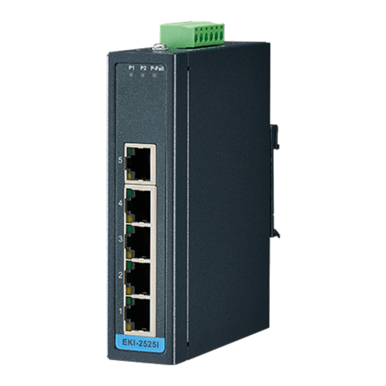
EKI-2525/2525I
5-port 10/100Base-TX Industrial
Unmanaged Ethernet Switch
EKI-2528/2528I
8-port 10/100Base-TX Industrial
Unmanaged Ethernet Switch
User Manual
Table of
Contents
Previous
Page
Next
Page
1
2
3
4
5
Advertisement
Table of Contents
Troubleshooting
Overview
10
Troubleshooting
26
Need help?
Do you have a question about the EKI-2525I and is the answer not in the manual?
Ask a question
Questions and answers
Related Manuals for Advantech EKI-2525I
Switch Advantech EKI-2528 User Manual
5/8-port 10/100base-tx industrial unmanaged ethernet switch (28 pages)
Network Router Advantech EKI-2525 User Manual
Eki-2525 5-port 10/100base-tx industrial unmanaged ethernet switch/eki-2528 8-port 10/100base-tx industrial unmanaged ethernet switch (28 pages)
Switch Advantech EKI-2525M User Manual
Industrial 5-port unmanaged ethernet switch with 1/2-port 100fx (30 pages)
Switch Advantech EKI-2525P User Manual
5-port industrial poe unmanaged ethernet switch (28 pages)
Switch Advantech EKI-2526PI User Manual
6-port industrial unmanaged ethernet switch with 4-port poe (28 pages)
Switch Advantech EKI-2548I User Manual
8-port 10/100tx managed ethernet switch with wide operating temperature (73 pages)
Switch Advantech EKI-2525I-BE User Manual
5/8-port 10/100base-tx industrial unmanaged ethernet switch (28 pages)
Switch Advantech EKI-2525-BE User Manual
5/8-port 10/100base-tx industrial unmanaged ethernet switch (28 pages)
Switch Advantech EKI-2525PA User Manual
5-port industrial unmanaged with 4-port poe (28 pages)
Switch Advantech EKI-2528i-m12 Startup Manual
8 port m12 unmanaged industrial ethernet switch, ip67 (2 pages)
Switch Advantech EKI-2528I User Manual
5-port 10/100base-tx industrial unmanaged ethernet switch , 8-port 10/100base-tx industrial unmanaged ethernet switch (28 pages)
Switch Advantech EKI-2728MI User Manual
6g + 2g fiber port industrial unmanaged gigabit ethernet switch (28 pages)
Switch Advantech EKI-2728 User Manual
8-port industrial unmanaged gigabit ethernet switch (28 pages)
Switch Advantech EKI-2728-AE User Manual
8-port industrial unmanaged gigabit ethernet switch (28 pages)
Switch Advantech EKI-2725 User Manual
5-port industrial unmanaged gigabit ethernet switch (28 pages)
Switch Advantech EKI-2728I User Manual
8-port industrial unmanaged (23 pages)
This manual is also suitable for:
Eki-2525
Eki-2528
Eki-2528i
Table of Contents
Print
Rename the bookmark
Delete bookmark?
Delete from my manuals?
Login
Sign In
OR
Sign in with Facebook
Sign in with Google
Upload manual
Upload from disk
Upload from URL


Need help?
Do you have a question about the EKI-2525I and is the answer not in the manual?
Questions and answers