Radwin 5000 HPMP User Manual
Point to
multipoint broadband wireless
Hide thumbs
Also See for 5000 HPMP:
- User manual (322 pages) ,
- User manual (121 pages) ,
- User manual (518 pages)

Related Manuals for Radwin 5000 HPMP


Summary of Contents for Radwin 5000 HPMP
- Page 1 USER MANUAL RADWIN 5000 HPMP POINT TO MULTIPOINT BROADBAND WIRELESS Release 3.3.30...
-
Page 2: User Manual
RADWIN protected under international copyright law and shall be and remain solely with RADWIN. The RADWIN name is a registered trademark of RADWIN. No right, license, or interest to such trademark is granted hereunder, and you agree that no such right, license, or interest shall be asserted by you with respect to such trademark. - Page 3 Italy Ciudad Merliot El Salvador Tel:+390815564116 Tel: +503 2278-5628 sales@radwin.com Fax: +39335433620 Email: salesit@radwin.com Email: RADWIN South East Asia All Season Mansion 87/38 Wireless Road Lumpinee Bangkok ,10330 Thailand Tel: +66811707503 sales@radwin.com Email: RADWIN 5000 HPMP User Manual Release 3.3.30...
-
Page 4: Regulatory Compliance
The installer should configure the output power level of antennas according to country regulations and antenna type. RADWIN 5000 HPMP User Manual Release 3.3.30... - Page 5 2. For protection of ODU against direct lightning strikes, appropriate requirements of NFPA 780 should be considered in addition to NEC. 3. For Canada, appropriate requirements of the CEC 22.1 including Section 60 and additional requirements of CAN/CSA-B72 must be considered as applicable. RADWIN 5000 HPMP User Manual Release 3.3.30...
- Page 6 Chapter 10 Hub Site Synchronization Chapter 11 Using the RADWIN GSU Part 5: Advanced Installation Topics Chapter 12 Software Upgrade Chapter 13 VLAN Functionality with RADWIN 5000 HPMP Chapter 14 False Radar Mitigation Facilities Chapter 15 FCC/IC DFS Considerations Chapter 16 Quality of Service...
-
Page 7: Table Of Contents
Three Sector Display Views ................4-9 Continuing with our Example Sector ............4-13 Exploring the RADWIN Manager Main Window - HBS ........4-16 Exploring the RADWIN Manager Main Window - HSU ........4-27 Logging on to a HSU ................. 4-27 Setting RADWIN Manager Preferences ............ - Page 8 Hardware Installation ................10-2 ODU/HSS Unit Connection Pinout ............... 10-6 Radio Frame Pattern (RFP)................. 10-6 Sector Configuration and HSS ..............10-8 Chapter 11 Using the RADWIN GSU What is it for..................... 11-1 RADWIN GSU Functionality ................ 11-1 Typical GSU Scenarios ................11-1 GSU Redundancy ..................
- Page 9 What is the Software Upgrade Utility? ............12-1 Upgrading an Installed Sector ..............12-2 Downgrading HSU Software ............... 12-5 Chapter 13 VLAN Functionality with RADWIN 5000 HPMP VLAN Tagging - Overview ................13-1 Scope of this Chapter ................13-1 Requirements.................... 13-1 VLAN Tagging ...................
- Page 10 Appendix E Setting Antenna Parameters Antenna Issues ...................E-1 About Single and Dual Antennas..............E-1 Considerations for Changing Antenna Parameters ..........E-3 Appendix F Regional Notice: French Canadian Procédures de sécurité ................F-1 Installation sur pylône et mur............... F-3 Index RADWIN 5000 HPMP User Manual Release 3.3.30...
-
Page 11: List Of Figures
....1-8 IGURE SING AN THERNET REPEATER WITH LIGHTNING PROTECTORS 3-1 ODU M ................3-3 IGURE OUNTING KIT 3-2 RADWIN 5505 HSU - R ........... 3-3 IGURE EAR AND METAL TIE 3-3 M ................3-3 IGURE OUNTING ADAPTER 3-4 ODU F... - Page 12 ..........9-10 IGURE ETTING THE UPPER TRAFFIC THRESHOLD 9-8 HBS - P ......9-10 IGURE ERFORMANCE ONITORING REPORT ALID DATA 9-9 HBS - P ..9-11 IGURE ERFORMANCE ONITORING REPORT HOWING INVALID DATA RADWIN 5000 HPMP User Manual Release 3.3.30...
- Page 13 IGURE 17-4 M ..............17-2 IGURE OUNTING ON A POLE 17-5 M ..............17-3 IGURE OUNTING ON A 17-6 RADWIN 5505 HSU - R ........17-4 IGURE EAR AND METAL TIE 17-7 M ................ 17-4 IGURE OUNTING ADAPTER 18-1 G ............
- Page 14 ................... F-3 IGURE GRANDE CLAME ..................F-3 IGURE PETITE CLAME ....................F-3 IGURE BRAS F-4 M ..............F-4 IGURE ONTAGE SUR UN PYLÔNE F-5 M ................ F-5 IGURE ONTAGE SUR UN MUR RADWIN 5000 HPMP User Manual Release 3.3.30 xiii...
-
Page 15: List Of Tables
9-4 RADWIN M ............. 9-14 ABLE ANAGER ESSAGES 10-1 ODU/HSS U ..........10-6 ABLE ONNECTION INOUT 10-2 R - RADWIN 5000 HBS ......10-7 ABLE ADIO RAME ATTERN ABLE 10-3 R - RADWIN 2000 ........10-7 ABLE ADIO RAME ATTERN... -
Page 16: Part 1: Basic Installation
USER MANUAL RADWIN 5000 HPMP POINT TO MULTIPOINT BROADBAND WIRELESS Release 3.3.30 Part 1: Basic Installation... -
Page 17: Chapter 1 Introduction
Chapter 1 Introduction Welcome to RADWIN 5000 HPMP! RADWIN 5000 HPMP delivers up to 250Mbps and is the ideal choice for last mile enterprise connectivity and high-end applications that demand assured performance with guaranteed bandwidth per subscriber. RADWIN 5000 HPMP sector base station delivers up to 250Mbps, providing the highest end user capacity in the market to best support data and high resolution video applications, today and tomorrow. -
Page 18: Some Terminology
Unit radios. The SUs are sometimes called Customer Premises Equipment (CPEs). The terminology comes from the field of telephony. The RADWIN 5000 HPMP product suite supports considerably higher capacity than other cur- rent technologies (such as Wi-Max). We distinguish between generic BSs and SUs and RAD- WIN units, relabeling the latter, HBSs and HSUs (H = high capacity). - Page 19 Key features of RADWIN 5000 HPMP Chapter 1 There are only two functional changes to the RADWIN Manager since release 3.3.10. Visually, the RADWIN Manager has only changed in one other repect: The icons representing the HSU types for the Map view (only)
-
Page 20: Figure 1-1 Single Sector Base Station
ODU antenna A standard HSU consists of a RADWIN 55xx HSU ODU. It may be a small form factor (SFF) model with a built in antenna, or a regular integrated or connectorized unit. The latter should use a dual pole antenna for best performance. -
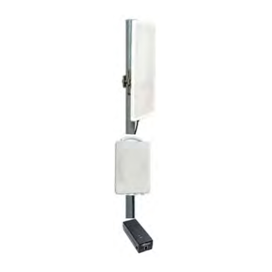
Page 21: Figure 1-5 Small Form Factor Hsu With Ac Power Feeding
Note the FCC/IC cautionary notice on page 3-5. IDU-H The IDU-H provides aggregation for multiple RADWIN links and HBSs at a hub location. It supports all RADWIN ODUs. It features - • Up to 6 PoE Interfaces (PoE legacy mode / RADWIN PoE) •... -
Page 22: Figure 1-8 General Gsu Configuration
It synchronizes the transmission timing of multiple Hub-Sites to the same clock source thus eliminating mutual interference. Figure 1-8: General GSU configuration For further details about the HSS unit, see Chapter For further details about the GSU, see Chapter RADWIN 5000 HPMP User Manual Release 3.3.30... - Page 23 Lightning Protector Chapter 1 Lightning Protector Lightning protection is mandatory for radio links. RADWIN supplies a lightning protector device designed for use with RADWIN products. Figure 1-9: Using lightning protectors Left: RADWIN Lightning Protector Right: RADWIN Chapter 18 for details about this device.
-
Page 24: Figure 1-10 Using An Ethernet Repeater With Lightning Protectors
Ethernet Repeater Chapter 1 Ethernet Repeater The RADWIN Ethernet repeater enables you to extend the PoE to ODU cable beyond the 100m limit (but no more than 200m). The unit looks physically like the lightning protection device in Figure 1-18. It’s use is very simple as shown in the following schematic: Figure 1-10: Using an Ethernet repeater with lightning protectors. -
Page 25: Conventions Used In This Manual
Where a term is defined or introduced for the first time, it is shown in Boldface. You will have noticed this usage in the Terminology section above. Software The RADWIN Manager is a Microsoft Windows application following the user interface con- ventions of familiar Microsoft Windows programs. Viewing and Printing This manual is optimized for viewing online as a PDF file. -
Page 26: Chapter 2 Site Preparation
RADWIN 5000 HPMP offers a wide operating frequency range. A free frequency channel must be determined within the operating range, for optimum performance. -
Page 27: Stage 1: Preliminary Survey
7. If the sites chosen do not meet requirements, consider alternative sites. 8. Use the Link Budget Calculator (on the CD supplied with the equipment or using the RADWIN Manager) to determine the expected performance. RADWIN 5000 HPMP User Manual... -
Page 28: Stage 2: Physical Survey
The ambient outdoor operating temperature should be -35 to 60C (-31 to 140F). Additional Indoor Site Requirements The ambient operating temperature should be 0 to 50°C (32 to 122 °F) at a humidity of up to 90%, non condensing RADWIN 5000 HPMP User Manual Release 3.3.30... -
Page 29: Stage 3: Rf Survey
RADWIN unit. • If one or more collocated units are not RADWIN units, ensure that there is a physical separation of at least three meters between a RADWIN unit and any other collocated radio on the site. -
Page 30: Chapter 3 Hardware Installation
Hardware Installation This chapter sets out the requirements and procedures for the hardware installation and alignment of a RADWIN 5000 HPMP sector in accordance with the prior planning as set out in Chapter 2. It is intended to guide qualified field technicians. -
Page 31: Package Contents
• Use extreme care when working at heights. • When using an AC power source for RADWIN 5000 HPMP PoEs always use the AC power adapter supplied by RADWIN. • Use the right tools. In addition to standard tools required for any kind of ODU or... -
Page 32: Figure 3-3 Mounting Adapter
Figure 3-1: ODU Mounting kit The small form factor HSUs use a mounting kit adapter or metal ties: Figure 3-2: RADWIN 5505 HSU - Rear and metal tie The mounting ties are threaded through the mounting slots provided and the unit mounted on a pole. - Page 33 The ODUs come in the basic form factors as shown in Figure 3-4 below: Front Rear Front Rear Figure 3-4: ODU Form Factors: Top - Standard ODU package, Bottom - Small form factor HSU • Integrated Antenna ODU RADWIN 5000 HPMP User Manual Release 3.3.30...
-
Page 34: Figure 3-5: External Antennas For Use With Radwin 5000 Hbs - Left: 60° Or 90° Flat External; Right: 120° Integrated
The HBS requires a dual pole sector antenna. HSUs may use any suitable dual pole directional antenna. External antennas are available for the RADWIN 5000 HPMP radios, varying in operating fre- quencies, form factor, size and gain. Figure 3-5: External Antennas for use with RADWIN 5000 HBS - Left: 60°... -
Page 35: Figure 3-7: Gbe Poe Device
Power Over Ethernet (PoE) Devices Chapter 3 Figure 3-6: External Antennas for use with RADWIN 55xx HSU - Left: Standard integrated; center and right, parabolic, different sizes and gains. See the RADWIN products catalog for a more detailed offering of external antennas. External antennas are also available from third party antenna vendors. -
Page 36: Figure 3-8: Ruggedized Dc-Poe Device: Input
Gigabit performance on the HBS. Figure 3-8: Ruggedized DC-PoE Device: Input is -20 to -60 VDC (single input) IDU-H Aggregation Unit Package Contents The IDU-H package contains four items as shown in Figure 3-9: RADWIN 5000 HPMP User Manual Release 3.3.30... - Page 37 IDU-H Aggregation Unit Chapter 3 Figure 3-9: IDU-H kit contents The IDU-H may be installed in single or double configurations: Figure 3-10: IDU-H front view - single configuration RADWIN 5000 HPMP User Manual Release 3.3.30...
-
Page 38: Front Panel
Yellow WAN (2xRJ45 LEDs) Link / Activity Duplex or Port’s PoE status (configurable) LAN (2xRJ45 LEDs) Link / Activity Duplex SFP (2 panel mounted LEDs) Link / Activity Duplex Connecting power to the IDU-H The IDU-H has redundant power connection circuits. An enlarged schematic of the power connectors is shown in below: RADWIN 5000 HPMP User Manual Release 3.3.30... - Page 39 The GPS-based synchronization unit (GSU) is designed to handle inter-site interferences under large-scale deployment scenarios. The RADWIN GSU is an outdoor unit consisting of a standard WinLink 1000 enclosure, a GPS antenna and a PoE device. The RADWIN GSU is connected to the HSS Unit using a standard HSS cable. It synchronizes...
-
Page 40: Additional Tools And Materials Required
Figure 3-15: General GSU configuration Chapter 11 for further details about the use of RADWIN GSU. Additional Tools and Materials Required The following is a list of the equipment and materials required to install RADWIN 5000 HPMP hardware. Tools and Materials •... -
Page 41: Hardware Installation Sequence
Hardware Installation Sequence Chapter 3 Hardware Installation Sequence The following steps are required to install a RADWIN 5000 HPMP system: 1. Mounting the ODUs, page 3-13. 2. Mounting the external antennas (if used), page 3-13. 3. Mounting the Lightning Protection devices (if used), page 3-14. -
Page 42: Outdoor Installation
Devices below. The supplied mounting kit is used to mount the antenna onto a pole. The antennas must be aligned for maximum throughput. Never stand in front of a live antenna! Warning RADWIN 5000 HPMP User Manual Release 3.3.30 3-13... - Page 43 The use of lightning protection is dependent on regulatory and end user requirements. The RADWIN 5000 HPMP ODU is designed with surge limiting circuits to minimize the risk of dam- age due to lightning strikes. RADWIN recommends the use of additional surge arrestor devices to protect the equipment from nearby lightning strikes.
- Page 44 The use of lightning protection is dependent on regulatory and end user requirements. The RADWIN 5000 HPMP ODU is designed with surge limiting circuits to minimize the risk of dam- age due to lightning strikes. RADWIN recommends the use of additional lightning protector devices to protect the equipment from nearby lightning strikes.
-
Page 45: Figure 3-18 Sing An Ethernet Repeater With Lightning Protectors
Mounting the Ethernet Repeater Chapter 3 Mounting the Ethernet Repeater The RADWIN Ethernet repeater enables you to extend the PoE to ODU cable beyond the 100m limit (but no more than 200m). The unit looks physically like the lightning protection device in Figure 3-17. - Page 46 5. Wrap two layers of any scotch vinyl plastic electrical type (e.g Scotch Super 88 Vinyl Plastic Tape from 3M) to protect the joints as shown in Figure 3-21. Ensure that the RADWIN 5000 HPMP User Manual Release 3.3.30 3-17...
- Page 47 IDU. Figure 3-22: Mounted and strapped to the pole Outdoor Connections To complete the outdoor connections: 1. Connect the ground cable to the ODU chassis as marked on the ODU. RADWIN 5000 HPMP User Manual Release 3.3.30 3-18...
-
Page 48: Aligning Hsus To A Hbs
6. Slowly turn the HSU antenna back towards the position of the HBS, listening to the tone until the best signal is reached. See the following figure for audible signal varia- tions. RADWIN 5000 HPMP User Manual Release 3.3.30 3-19... -
Page 49: Figure 3-23 Beep Sequence For Antenna Alignment
Long beep and short pause is 'signal quality decreased' Note • One beep and a long pause is 'no air link' • Any other signal does not relate to antenna alignment 7. Secure the HSU antenna to the pole/wall. RADWIN 5000 HPMP User Manual Release 3.3.30 3-20... -
Page 50: Part 2: Sector Installation
USER MANUAL RADWIN 5000 HPMP POINT TO MULTIPOINT BROADBAND WIRELESS Release 3.3.30 Part 2: Sector Installation Sector Installation... -
Page 51: What We Will Do Here
This chapter is a quick “hands-on” tour of a running sector. We show you how to install the RADWIN Manager software on your managing PC, connect it to an operating base station and then log on. We then explain the use of the various objects on the RADWIN Manager main window. - Page 52 Installing the Software Chapter 4 Installing the Software Any PC running the RADWIN Manager application can be used to configure a RADWIN 5000 HPMP sector. To install the RADWIN Manager application: 1. Insert the CD into the CD/DVD drive of your computer.
- Page 53 Getting Started with the RADWIN Manager Chapter 4 Getting Started with the RADWIN Manager We will look at a pre-configured fixed sector, setup as follows: Table 4-2: Preconfigured setup Unit Location Attribute Value Remark IP Address 192.168.10.200 All communicating HSUs and HBS in Net Mask 255.255.255.0...
- Page 54 Getting Started with the RADWIN Manager Chapter 4 Table 4-2: Preconfigured setup (Continued) Unit Location Attribute Value Remark IP Address 192.168.10.101 All communicating HSUs and HBS in Net Mask 255.255.255.0 the same subnet Default Gateway 0.0.0.0 Fixed HSU type Contact Haydn HFU.01.01...
-
Page 55: Figure 4-1 Pinging The Base Station
Any other response from ping means that the HBS ODU is not responding. Check your Ethernet connection and that both the PoE and ODU are switched on and then try again. If you do not succeed, seek assistance from RADWIN Customer Support. Pinging the HSUs should yield similar responses. -
Page 56: The Radwin Manager Log-On Concept
Chapter 4 Figure 4-2: Log-on window The RADWIN Manager log-on Concept The RADWIN Manager provides three levels of access in one of two entry modes. To see them, click Options at any time in the Log on window (Figure 4-2 above). -
Page 57: Figure 4-4 Log On Window Exposing The User Types
The Network Manager should change the default passwords as soon as possible. Continuing the log-on procedure: 5. If your User Type is not Operator, then choose it now. 6. Enter the password. RADWIN 5000 HPMP User Manual Release 3.3.30... -
Page 58: Log-On Errors And Cautions
If the IP address chosen is invalid or the sector is unreachable, the following error message will be displayed: Figure 4-6: Unreachable device message Incorrect Password If you type an incorrect password in the Login window, the follwing message will be dis- played: RADWIN 5000 HPMP User Manual Release 3.3.30... -
Page 59: Three Sector Display Views
To deal with lost or forgotten Community Strings: 1. Send an email request for to RADWIN Customer Support for an alternative key. Your email must include the ODU serial number shown on the adhesive sticker on rear of one of your ODUs. -
Page 60: Figure 4-8 Default Sector Display - Table View
Map View Chapter 4 Figure 4-8: Default Sector display - Table view Map View If you have an Internet connection, you may use Map view. The RADWIN Manager main window looks like this: RADWIN 5000 HPMP User Manual Release 3.3.30... -
Page 61: Figure 4-9 Sector Display - Map View
“in the middle of nowhere”. Later we show you how to change the positions of the HSU icons on the map. List View The third sector display type is List view. It looks like this: RADWIN 5000 HPMP User Manual Release 3.3.30 4-11... -
Page 62: Figure 4-10 Sector Display - List View
Table view and List view. The active tab (Table view in the illustration) is shown enlarged. Display View Persistence The last display view used will be that opened at your next restart or log on to the RADWIN Manager. RADWIN 5000 HPMP User Manual Release 3.3.30... -
Page 63: Continuing With Our Example Sector
2. Click the Coordinates button to open the Coordinates window and enter the required latitude and longitude. You may enter the coordinates in decimal or degrees/minutes/seconds using the input template shown below: RADWIN 5000 HPMP User Manual Release 3.3.30 4-13... - Page 64 1. Select the unit to move by clicking it. It is surrounded by a brown box. 2. Mouse-over the top edge of the box to get a context button bar as shown in. RADWIN 5000 HPMP User Manual Release 3.3.30...
- Page 65 The change is then carried out. The foregoing change confirmation is important: There is no “undo” function. If you inadvertently move the unit to a wrong place, you will have to restore its position by hand. Note RADWIN 5000 HPMP User Manual Release 3.3.30 4-15...
-
Page 66: Exploring The Radwin Manager Main Window - Hbs
Exploring the RADWIN Manager Main Window - HBS Chapter 4 Exploring the RADWIN Manager Main Window - HBS The following sections describe the panels of main window shown in Figure 4-8. HBS Main Button Menu Figure 4-13: HBS main button menu... -
Page 67: Figure 4-15 Base Station Detail Panel
Table 4-7: HBS Detail Panel button bar functions Menu Purpose Reference Icon HBS Configuration Chapter 6 Recent Events Log page 9-7 Performance Monitor page 9-9 Active Alarms page 9-15 Spectrum View Chapter 20 RADWIN 5000 HPMP User Manual Release 3.3.30 4-17... - Page 68 The foregoing event types include events from all links for which this managing computer has been defined as the traps address. Only events from RADWIN equipment will be shown. Note Alarms (traps) are displayed in the Events Log in the lower panel of the main window. The Events Log may be saved as a text file.
-
Page 69: Figure 4-16 Events Log Panel
IP address of the ODU that initiated alarm. For complete information about internal traps and alarms see Chapter The events are displayed in the Events Log in the lower right-hand panel of the RADWIN Manager main window: Figure 4-16: Events Log panel The events log provides a color coded event list. - Page 70 If you mouse-over the colored RSS area, you will receive a tool tip telling you that RSS for Radio 1 is higher than for Radio 2, or something similar. We will provide further detail about these color codes below. RADWIN 5000 HPMP User Manual Release 3.3.30 4-20...
- Page 71 Table 4-8: HSU Status ball color codes Color Description Green Registered, in sync Registered, no sync Grey Deregistered Purple Authentication error Blue “Violated” Belongs to another sector Right click a HSU to get its context menu: RADWIN 5000 HPMP User Manual Release 3.3.30 4-21...
- Page 72 Chapter 4 Figure 4-21: HSU display - context menu (right click) Map View Here again is the Map view of the HBS Main Window: Figure 4-22: HBS Main Window - Map view RADWIN 5000 HPMP User Manual Release 3.3.30 4-22...
- Page 73 Figure 4-24: Navigation Tool bar Table 4-10: Navigation tool bar button unctions Menu Icon Purpose Show/Hide the HBS/HSU Status lights (Figure 4-23) Show/Hide the HBS/HSU Status boxes Center on the sector RADWIN 5000 HPMP User Manual Release 3.3.30 4-23...
- Page 74 Here is a copy/ pasted example: -37.58896, 145.69000. The HSU Status box The following case has colored fields indicating a problem requiring your attention: RADWIN 5000 HPMP User Manual Release 3.3.30 4-24...
- Page 75 The arrow on the top right hand corner can be used to minimize or restore full detail. Here is the HSU status box of Figure 4-20 minimized: This device is useful for a large sector with a small display. RADWIN 5000 HPMP User Manual Release 3.3.30 4-25...
- Page 76 Figure 4-28: HSU On HBS display - extract. Scroll right for more HSU fields If you have a large number of HSUs in the sector, it may be helpful to filter the display. You have the following choices: RADWIN 5000 HPMP User Manual Release 3.3.30 4-26...
-
Page 77: Exploring The Radwin Manager Main Window - Hsu
Exploring the RADWIN Manager Main Window - HSU Chapter 4 The button bar in Figure 4-28 follows the same pattern as the context menus in Figure 4- 21.. Table 4-11: HBS main window list display context menu and button bar functions... - Page 78 Upon clicking OK to dismiss the caution, we get a variation of the previous main window: Figure 4-30: Opening RADWIN Manager window - HSU The direct log on window differs only in the bottom status bar where the Connection Mode...
- Page 79 Run and store diagnostics for all or some members of a sector Log Off Return to log-on window Help Link Budget Calculator Check for updates About Help Button View this User Manual HSU Link Status RADWIN 5000 HPMP User Manual Release 3.3.30 4-29...
-
Page 80: Setting Radwin Manager Preferences
They are also functionally identical for both the HBS and HSUs. Each technician servicing a sector will need to set up his managing computer (typically a laptop) with his own preferences. Note RADWIN 5000 HPMP User Manual Release 3.3.30 4-30... - Page 81 For a HSU, it will record the information just for that HSU. You should use distinctive file names for HBS and HSU Monitor files. The content of the Monitor file will be discussed in more detail in Chapter RADWIN 5000 HPMP User Manual Release 3.3.30 4-31...
- Page 82 You may also choose a location and file name for the events log for storage. These settings are again, per HBS or HSU. To avoid over-writing, you should use file names reflecting their source ODU. RADWIN 5000 HPMP User Manual Release 3.3.30 4-32...
- Page 83 Advanced Restore Alerts Many alert messages in the RADWIN Manager have an option of the form “Do not show this message again”. These alert messages can be reverted to their default state (shown) by click- ing the Restore Alerts button. You will be asked to confirm: Check for Updates If you are not connected to the Internet, disable the Check for updates check box.
-
Page 84: What Comes Next
Chapter 4 What Comes Next? The purpose of this chapter was to offer an overview of a running RADWIN 5000 HPMP a sec- tor. The next three chapters will cover respectively, detailed sector setup considerations, sec- tor management and monitoring and diagnostics. The foregoing background should provide sufficient “signposts”... -
Page 85: Chapter 5 Installing The Sector
Bringing up the HSUs - configuration and registration The same RADWIN Manager program is used for both the HBS and the HSUs. Much of the process is common to both types of ODU. We will cover the HBS in detail; for the HSUs we will concentrate on those items which are different. -
Page 86: Working With Nomadic Hsus
Geo- graphic positioning data. Prior to commencing, you should have a written sector plan along the lines of Table 5-2. RADWIN 5000 HPMP User Manual Release 3.3.30... -
Page 87: Default Radwin 5000 Hpmp Settings
Default RADWIN 5000 HPMP Settings Chapter 5 Default RADWIN 5000 HPMP Settings The default settings of the RADWIN 5000 HPMP configuration parameters are listed in Table 5-1 below. Table 5-1: Default settings Unit Parameter Default Value IP Address 10.0.0.120 Net Mask 255.0.0.0... - Page 88 Default RADWIN 5000 HPMP Settings Chapter 5 For convenience, we repeat the table of parameters used in our demonstration sector. Param- eters not listed are left at their default values: Table 5-2: Parameter values used in the demonstration sector Unit...
- Page 89 Default RADWIN 5000 HPMP Settings Chapter 5 Table 5-2: Parameter values used in the demonstration sector (Continued) Unit Location Attribute Value Remark IP Address 192.168.10.101 All communicating HSUs and HBS in Net Mask 255.255.255.0 the same subnet Default Gateway 0.0.0.0...
-
Page 90: Configuring The Sector Out Of The Box - Ip Addresses
10.0.0.100, subnet mask 255.255.255.0 and Default Gateway 0.0.0.0. Ensure that you have a direct LAN connection to the HBS, run the RADWIN Manager and log- on to it. Figure 5-1: Logging on with factory default IP address... - Page 91 Check the Read/Write enable box to carry out instal- lation procedures. • Network log on (IP address to the ODU) is recommended. Here is the initial main display using Local Connection: RADWIN 5000 HPMP User Manual Release 3.3.30...
- Page 92 3. Register the HSUs to the HBS for traffic 4. Complete HSU configuration including HSU Connection Table and any other required fine tuning. To activate a HBS: 1. Click the Activate button. The Activation Wizard opens. RADWIN 5000 HPMP User Manual Release 3.3.30...
- Page 93 HSUs only, the split is immaterial. If the sec- tor is part of a network having non-fixed HSUs, then each Sector ID for each partici- pating sector should have the same four character Network ID. The remaining part is RADWIN 5000 HPMP User Manual Release 3.3.30...
- Page 94 RF planning. 3. Open the Coordinates dialog to set the location of the HBS in accordance with Table 5-2: 4. The Link Password may also be changed by clicking Change: RADWIN 5000 HPMP User Manual Release 3.3.30 5-10...
- Page 95 5. From the previous Activation Wizard window, click Next. Here you may enter the IP details if didn’t do it earlier. Click Next. 6. The next window is used to set the frequency and channels. RADWIN 5000 HPMP User Manual Release 3.3.30 5-11...
- Page 96 The default frequency is the lowest available (5.735 GHz) in the operating band, here, 5.730 - 5.845 GHz FCC/IC. 7. Click Other to see other available bands for this HBS. 8. For our purposes, we choose 5.820 GHz: RADWIN 5000 HPMP User Manual Release 3.3.30 5-12...
- Page 97 9. Choose the required Channel Bandwidth: If your hardware supports 200 Mbps net aggregate capacity, you should chose 40 MHz Channel Bandwidth to enable it. Note 10. To use ACS, check the Automatic Channel Selection box: RADWIN 5000 HPMP User Manual Release 3.3.30 5-13...
- Page 98 Chapter 5 You can perform a customized channel selection or click Select All to check all the channel boxes as shown: 11. Click Next. The Antenna type and Tx Power window is presented: RADWIN 5000 HPMP User Manual Release 3.3.30 5-14...
- Page 99 Choose your Antenna Type, Required Tx Power, Antenna Gain and Cable Loss. We will set Required Tx Power to 5 dBm for our example. Click Next. 12. The Summary window of the Wizard is displayed. RADWIN 5000 HPMP User Manual Release 3.3.30 5-15...
- Page 100 Check that all information showed is correct and click Activate. After a few moments the sector HSUs will be displayed in the Manager HSU panel. The field-installed HSUs appear ina Table view: RADWIN 5000 HPMP User Manual Release 3.3.30 5-16...
-
Page 101: Configuring A Fixed Hsu From The Hbs
The procedures in this section should be carried out for each fixed HSU in the sector. To configure an fixed HSU from the HBS: 1. Right click an HSU to get its context menu: RADWIN 5000 HPMP User Manual Release 3.3.30 5-17... - Page 102 Location is a site name - typically a building or tower name. Contact is the contact person at that Location and Name is the Contact location. It might be just a tele- phone number. Here are our entries: RADWIN 5000 HPMP User Manual Release 3.3.30 5-18...
- Page 103 3. Set the Coordinates (latitude and longitude) for the HSU as shown in the Sector Plan: 4. Set the HSU Tx Power (possibly as required by regulations). Click Tx & Antenna. The following dialog is displayed: RADWIN 5000 HPMP User Manual Release 3.3.30 5-19...
- Page 104 Set the Antenna Connection Type, Antenna Type, Required Tx Power, Antenna Gain and Cable Loss as required. For our example, we use external antennas and we set Tx Power to 5 dBm. If you click apply, you receive the following confirmation request: RADWIN 5000 HPMP User Manual Release 3.3.30 5-20...
- Page 105 6. Click OK. The HSU display area refreshes with the newly configured HSU in its new location in the sector. 7. Reopen the Configuration dialog for the HSU and then open the Management tab. RADWIN 5000 HPMP User Manual Release 3.3.30 5-21...
-
Page 106: Configuring A Nomadic Hsu From The Hbs
Configuring a nomadic HSU From the HBS To configure a nomadic HSU from the HBS: 1. Carry out steps 1 to 7 as in the previous section for a fixed HSU. 2. Open the Nomadic tab: RADWIN 5000 HPMP User Manual Release 3.3.30 5-22... - Page 107 (for example) different QoS parameters. Choose level A and then OK. The number of time slots allocated to the HSU will be updated during the registration process. You are offered the following confirmation message: RADWIN 5000 HPMP User Manual Release 3.3.30 5-23...
-
Page 108: Registering A Fixed Hsu For Service
2. Click Register... If you did not configure the antenna type for the HSU, you are asked to do so now: Choose the required type and click OK. The Registration window opens: RADWIN 5000 HPMP User Manual Release 3.3.30 5-24... - Page 109 The choice is HSU specific. For further details about MIMO/Diversity antenna mode, Appendix 5. Click the Evaluate button. Service evaluation takes a few seconds during which the window is darkened and inactive. Upon completion you may assign time slots to the HSU: RADWIN 5000 HPMP User Manual Release 3.3.30 5-25...
- Page 110 The Manager maintains dynamic monitoring of the sector for injection into the sector of HSUs elsewhere and accordingly reduces the available time slots. 6. Use the slider to choose the number of time slots to be allocated to the HSU. RADWIN 5000 HPMP User Manual Release 3.3.30 5-26...
- Page 111 Observe that the registered HSU icon LED is now green and that the time slots bar on the left reflects the proportion of time slots allocated. 9. Repeat steps 1 to 8 for other fixed HSUs. Here is the result for our example: RADWIN 5000 HPMP User Manual Release 3.3.30 5-27...
-
Page 112: Registering A Nomadic Hsu For Service
1. Open the HBS Configuration window and then its Nomadic Tab: Figure 5-7: HBS Nomadic Configuration 3. In the Add Devices window, click the Add spin wheel buttons and the time slots spin-wheels as shown. RADWIN 5000 HPMP User Manual Release 3.3.30 5-28... - Page 113 5. Exit the Configuration dialog. The Final Outcome Here is the outcome for our example: Figure 5-8: Fully functional mixed fixed and nomadic sector - Table view RADWIN 5000 HPMP User Manual Release 3.3.30 5-29...
- Page 114 If you do not see the changes as shown, a hard reset of the HSUs will cause them to appear. Note Here is the Map view showing HSU details for a fixed-nomadic sector: RADWIN 5000 HPMP User Manual Release 3.3.30 5-30...
-
Page 115: Registering The Hsus For Service
The throughput on this HSU has dropped to about half of its previous value. The other HSU is left unchanged. This underlines the flexibility of the RADWIN 5000 HPMP system which enables HSUs to be independently configured depending on their particular location. -
Page 116: Deregistering An Hsu
Notice that the HSUs remain registered, and will return to full service after the HBS is re-acti- vated. Deregistering an HSU A HSU may be deregistered by using the Deregister entry in an HSU context menu or using button from an HSU button bar. RADWIN 5000 HPMP User Manual Release 3.3.30 5-32... -
Page 117: Where Has My Hsu Gone
2. Activate the HBS in the usual way. 3. Open the Nomadic tab in the Configuration window. In the Save / Upload Settings window, click Upload. Figure 5-11: Preparing to upload the Nomadic file RADWIN 5000 HPMP User Manual Release 3.3.30 5-33... - Page 118 Start. After a few moments, the Status field indicates Done. The result is as expected: You will of course need to separately configure the participating HSUs. f we connect our con- figured nomadic HSU, we revert to our original sector: RADWIN 5000 HPMP User Manual Release 3.3.30 5-34...
- Page 119 2. Make any further changes to the displayed list using the Plus/Minus buttons. 3. Click Start to commence the process. 4. The list window will indicate the success or otherwise of the upload for each HBS. RADWIN 5000 HPMP User Manual Release 3.3.30 5-35...
-
Page 120: Part 3: Sector Management
USER MANUAL RADWIN 5000 HPMP POINT TO MULTIPOINT BROADBAND WIRELESS Release 3.3.30 Part 3: Sector Management... -
Page 121: Chapter 6 Managing The Sector
IDs and revision levels of the source and target HBSs are identical. Note The Refresh button restores the current window to its previous state abandoning any changes you made, provided that you did not click Apply or OK. RADWIN 5000 HPMP User Manual Release 3.3.30... - Page 122 These items are convenience fields. Name and Location are typically entered during HBS activation. You may like to change Contact here, not set during activation. The Coordinates button opens the same window as used during activation. RADWIN 5000 HPMP User Manual Release 3.3.30...
- Page 123 “picked up” by newly installed and registered HSUs. The only way to change the Operating Channel is by deactivation and reactivation. Channel Bandwidth and Channel Selection changes will all be sector-wide. RADWIN 5000 HPMP User Manual Release 3.3.30...
- Page 124 For the HBS, changes made here may affect link quality and in the case of antenna type, cause a sector re-sync. Changing the antenna type for an HSU will cause a re-sync to that site only. RADWIN 5000 HPMP User Manual Release 3.3.30...
- Page 125 Hub Site Sync [HSS] The External Pulses which might be detected, may come from a collocated HBS, a RADWIN 2000 ODU or a RADWIN GSU configured as Hub Sync Master. To enable HSS, check the Enabled check box. Ensure that the correct Operational state is selected - in our example, Hub Site Client - Continue Tx.
- Page 126 If you set the IP and related addresses correctly, there should be little to change here. The three sub-windows, Trap Destinations, VLAN Management and Protocol dialogs are generic to the HBS nad the HSUs (direct or over-the-air) and are discussed below. RADWIN 5000 HPMP User Manual Release 3.3.30...
- Page 127 VLAN for Management Management VLAN Configuration Figure 6-1: VLAN for Management VLAN IDs are used by RADWIN products in three separate contexts: Management VLAN, Traffic VLAN and Ethernet Ring. It is recommended that you use different VLAN IDs for each context.
- Page 128 • For further details about the Web Interface, see Chapter SNMP access is on by default for RADWIN 5000 HPMP and cannot be disabled. Note Telnet and Web Interface access modes when available, are site specific. If for example, you want Telnet access from specific sector members, you should enable it for these sites and dis- able it elsewhere.
- Page 129 Inventory Chapter 6 Inventory You might like to capture or copy the information here: The Inventory information will be required by Customer Support should you require assis- tance. RADWIN 5000 HPMP User Manual Release 3.3.30...
- Page 130 Here are the details: wireless-p2mp The default password is . Optionally, you can change the link password as explained here. To change the link password: 1. Open the Security tab (Figure 6-2). RADWIN 5000 HPMP User Manual Release 3.3.30 6-10...
- Page 131 Continue with the next step. 3. Enter a new password. 4. Retype the new password in the Confirm field. 5. Click OK. 6. Click Yes when asked if you want to change the link password. RADWIN 5000 HPMP User Manual Release 3.3.30 6-11...
- Page 132 ODU if the read-write or the read Community values are forgot- ten. A new Community value may be obtained from RADWIN Customer Support for the pur- pose of setting new Community. You must also have available the serial number or the MAC address of the ODU.
- Page 133 If both the read-write Community and the alternative Community key are unavailable, then an alternative Community key can be obtained from RADWIN Customer Support using the ODU serial number or MAC address. The serial number is located on the product label. The serial number and the MAC address are displayed in the Site Configuration inventory tab.
-
Page 134: Date And Time
To set the date and time: 1. Determine the IP address of the NTP server to be used. 2. Test it for connectivity using the command (Windows XP), for example: w32tm /stripchart /computer:216.218.192.202 RADWIN 5000 HPMP User Manual Release 3.3.30 6-14... - Page 135 4. Set your site Offset value in minutes ahead or behind GMT 5. To manually set the date and time, click Change and edit the new values. Figure 6-8: Change Date and Time 1. Greenwich Mean Time RADWIN 5000 HPMP User Manual Release 3.3.30 6-15...
- Page 136 The ODU Ethernet port mode is configurable for line speed (10/100/1000BaseT) and duplex mode (half or full duplex). Line speed 1000BaseT is only available if the HBS is connected to A GbE PoE device. RADWIN 5000 HPMP User Manual Release 3.3.30 6-16...
- Page 137 10) to collocated several HBSs (to cover adjacent sectors), they must all use the same Trans- mission Ratio. Figure 6-10: HBS Collocated client or independent unit If it is an HSS master, you will see something like this: Figure 6-11: HBS Collocated master RADWIN 5000 HPMP User Manual Release 3.3.30 6-17...
- Page 138 Moving the slider to the right in stages, yields the following: The effective available range for Asymmetric allocation is determined by channel bandwidth as shown as well as link distance. In this context, “link” is a collocated HBS or RADWIN 2000 ODU.
- Page 139 Nomadic Chapter 6 Nomadic page 5-24. Operations This section applies to both HBSs and HSUs. RADWIN 5000 HPMP User Manual Release 3.3.30 6-19...
- Page 140 Clicking the Restore Defaults button opens the following self explanatory dialog: License Activation You may add additional bands using the license Activation facility. Additional bands (if avail- able) are obtained using the Change Band function, described below. RADWIN 5000 HPMP User Manual Release 3.3.30 6-20...
-
Page 141: Hsu Connection Table
(a text file) you will need to use the License File option. In some instances it may involve purchasing the relevant license from RADWIN. You should contact Customer Service for details. You will find the technical steps required to obtain and... -
Page 142: Configuring An Hsu From The Hbs Main Window
A backup (full or configuration) may be restored top another HSU provided that the product IDs and revision levels of the source and target HSUs are identical. Note The Buzzer button may set or mute the buzzer. RADWIN 5000 HPMP User Manual Release 3.3.30 6-22... - Page 143 Apply or OK. We will work through each of the Configuration tabs in turn: System Figure 6-14: HSU Configuration window (HBS) These items are convenience fields. They are typically entered during registration. RADWIN 5000 HPMP User Manual Release 3.3.30 6-23...
- Page 144 Figure 6-15: HSU Configuration - Setting antenna type and parameters The remarks about changing the HBS parameters also apply here. Changing the antenna type will cause a re-sync between the HSU and the HBS. RADWIN 5000 HPMP User Manual Release 3.3.30 6-24...
- Page 145 Management Chapter 6 Management Figure 6-16: HSU Configuration - IP addresses The functionality is identical as that for the HBS. RADWIN 5000 HPMP User Manual Release 3.3.30 6-25...
- Page 146 Inventory Chapter 6 Inventory You should note the details for each HSU. RADWIN 5000 HPMP User Manual Release 3.3.30 6-26...
- Page 147 Security Chapter 6 Security You may change the SNMP community strings only for the HSU from here. You cannot change the Link password from an HSU. RADWIN 5000 HPMP User Manual Release 3.3.30 6-27...
- Page 148 Date & Time Chapter 6 Date & Time The functionality is identical as that for the HBS. RADWIN 5000 HPMP User Manual Release 3.3.30 6-28...
- Page 149 6-16. For the SU2-ACs (AC powered HSUs) Ethernet Ports Configuration panel is different: The ODU entry is disabled; only the LAN and PoE (out) ports are available for configuration: The LAN port has these options: RADWIN 5000 HPMP User Manual Release 3.3.30 6-29...
- Page 150 The Maximum Information Rate (MIR) was initially set during HSU Registration. You may change it here. VLAN Configuration For Traffic VLAN configuration, see Chapter QoS Configuration QoS configuration is described in Chapter RADWIN 5000 HPMP User Manual Release 3.3.30 6-30...
- Page 151 You cannot change a fixed HSU to a nomadic HSU here without prior deregistration. For a nomadic HSU, you may change its operating level or even revert it to a fixed HSU. RADWIN 5000 HPMP User Manual Release 3.3.30 6-31...
- Page 152 Nomadic Chapter 6 RADWIN 5000 HPMP User Manual Release 3.3.30 6-32...
- Page 153 You are using a Regulation requiring Radar Channel Avoidance and • You are logged on as Installer For this release, this feature for HSUs, is relevant to the 5.3 GHz ETSI and the 5.4 GHz FCC/ IC bands. RADWIN 5000 HPMP User Manual Release 3.3.30 6-33...
-
Page 154: Replacing An Hsu
1. Right click the defective unit for its context menu: It has a new item: Replace. 2. Click Replace. Your are offered a list of HSUs available as replacements. In our example there is one: 10.103. RADWIN 5000 HPMP User Manual Release 3.3.30 6-34... - Page 155 3. Select the required unit by clicking on it. 4. Click OK. You are asked to confirm before proceeding: 5. Click OK again. You receive further confirmation: Here is the final outcome: RADWIN 5000 HPMP User Manual Release 3.3.30 6-35...
-
Page 156: Updating Hsu Services
Diversity mode and change the HSU time slot allocation. Suspending an HSU You may break the link (cause a sync loss) to an un-registered HSU for a fixed amount of time. Here is the scenario: HSU 10.101 is not registered. RADWIN 5000 HPMP User Manual Release 3.3.30 6-36... -
Page 157: Changing The Sector Band
Sector Band you must be logged on to the HBS as Installer. In Installer mode, the right hand button, on the Base Station button bar has an extra function, Change Band. To change the Sector Band: 1. Click Change Band. A list of available Bands is displayed: RADWIN 5000 HPMP User Manual Release 3.3.30 6-37... - Page 158 Chapter 6 Figure 6-18: Change or Add Bands 2. Select the required Band and click OK. For our purposes, we choose 5.740-5.950 GHz Universal. The band is highlighted and right button is enabled. RADWIN 5000 HPMP User Manual Release 3.3.30 6-38...
- Page 159 Changing the Sector Band Chapter 6 Figure 6-19: Add/Change Band dialog 3. Click the right button. The following window opens: RADWIN 5000 HPMP User Manual Release 3.3.30 6-39...
- Page 160 Click OK to accept your choice. You are returned to the display in Figure 6-19. 5. Click OK again. The following cautionary message is displayed: 6. Click Yes to continue. After a short delay, you are offered a final confirmation: RADWIN 5000 HPMP User Manual Release 3.3.30 6-40...
- Page 161 WIN Ltd. The foregoing applies to both regulated and unregulated Bands. There is no connection between license fees payable to RADWIN for additional installed Bands (a hardware feature) and license fees payable to regulatory authorities for the right to use such Bands (a legal imposition).
- Page 162 Otherwise append the clipboard contents to your list. Select the whole list and save it to the clipboard. 4. Now carry out steps 2 to 5 in Figure 6-20. Step 2 will take you to a Web page, which looks something like this: RADWIN 5000 HPMP User Manual Release 3.3.30 6-42...
- Page 163 Key button. 6. The results of your request will be displayed with further instructions, A few minutes later, you should receive an email, containing in its body, a list of license keys. RADWIN 5000 HPMP User Manual Release 3.3.30 6-43...
-
Page 164: Configuration With Telnet
For example, if you run Telnet as follows, telnet 192.168.10.200 you will be asked for a user name and password. The Telnet log on user name is the password that you used to enter the RADWIN Manager admin (for example, the default: ). - Page 165 ODU. A new Telnet session to the ODU may be opened after the reset is complete. help Displays the available commands Table 6-3: HBS Telnet - Set Commands requiring Reset Command Explanation set secId <SectorID> Set new sector ID - Reset required. RADWIN 5000 HPMP User Manual Release 3.3.30 6-45...
- Page 166 ODU after the command completion set trap <index:1-10> <ipaddr> <port:0- Set a specific trap from the traps table (e.g. set trap 3 192.168..101 162) 65535> set readpw <oldpasswd> <passwd> Set the read access password (Read Community) RADWIN 5000 HPMP User Manual Release 3.3.30 6-46...
- Page 167 ODU. A new Telnet session to the ODU may be opened after the reset is complete. help Displays the available commands Table 6-6: HSU Telnet - Set Commands requiring Reset Command Explanation set secId <SectorID> Set new sector ID - Reset required. RADWIN 5000 HPMP User Manual Release 3.3.30 6-47...
-
Page 168: Chapter 7 Direct Hsu Configuration
Chapter Configuring an HSU Log on to the HSU either directly or over-the-air as shown in Chapter 4. For a registered HSU, you will see a display like this: RADWIN 5000 HPMP User Manual Release 3.3.30... - Page 169 For an unregistered HSU, the throughput (T-put) fields and the Sector ID field would be empty. If the HBS is deactivated, or the HSU is stand-alone you will see a display like this: Figure 7-2: Direct connection to a stand-alone HSU out of the box RADWIN 5000 HPMP User Manual Release 3.3.30...
- Page 170 The configuration tabs here differ from the HSU configuration tabs under the HBS Table view in one respect: There is an Air Interface tab, which varies in functionality, depending on whether the HSU is registered or not. RADWIN 5000 HPMP User Manual Release 3.3.30...
- Page 171 For a nomadic HSU or a HMU, the Air Interface display is different. First, the Sector ID is replaced by the Network ID. For a registered HSU, neither the Network ID or CBW can be touched: RADWIN 5000 HPMP User Manual Release 3.3.30...
- Page 172 Air Interface window: Figure 7-7: HSU Configuration - Air Interface Unregistered HSU Enter the Sector ID of the required HBS and click OK. The HSU should then “discover” the required HBS. RADWIN 5000 HPMP User Manual Release 3.3.30...
- Page 173 You are logged on as Installer For this release, this feature for HSUs, is relevant to the 5.3 GHz ETSI and the 5.4 GHz FCC/ IC bands. Configuration of False Radar Mitigation is covered in Chapter RADWIN 5000 HPMP User Manual Release 3.3.30...
-
Page 174: Chapter 8 Bringing Up A Mobility Sector
The detailed use of RADWIN 5000 HPMP elements in a Mobility application is beyond the scope of this manual. The purpose of this chapter is to demonstrate the use of RADWIN Man- ager in bringing up and managing a physically installed Mobility sector. In practice, one sector would be built by hand (as we will do below). -
Page 175: What You Need
A HMU must be able to send and receive service traffic while moving. To avoid service “glitches” while switching between successive HBSs, the HBS hand-over time must be very small. For RADWIN 5000 HPMP HBSs it is typically less than 500 ms, depending on selection of Mobility channels. -
Page 176: Preparing The Hbs
The first difference between a new activated mobile and fixed sector is that the HSUs do not appear in the Table view. Preparing the HBS Open the Configuration window and then the Mobility tab: RADWIN 5000 HPMP User Manual Release 3.3.30... - Page 177 The choice is part of RF planning for Mobility projects and is beyond the scope of this manual. We will pre-register three HSU slots to levels A, B and C and time slots to each level as shown: RADWIN 5000 HPMP User Manual Release 3.3.30...
- Page 178 64 time slots. Click Register, leave the maximum distance as is and click OK to leave the configuration window. Here is the result: We have “place holders” for the maximum allowable HMUs in the sector. RADWIN 5000 HPMP User Manual Release 3.3.30...
-
Page 179: Registering Hmus
To assign a HMU to a level by direct connection: 1. Log on to a HMU in the usual way. Here is the opening window: 2. Open the Configuration window. Update the system parameters. RADWIN 5000 HPMP User Manual Release 3.3.30... - Page 180 Registering HMUs Chapter 8 3. Open the Air Interface tab. RADWIN 5000 HPMP User Manual Release 3.3.30...
- Page 181 6. (Optional) Open the Management tab and set the HSU IP address. 7. Open the Mobility tab. Click the required level. We leave this HSU on A. We will place our other two HSUs in level B. RADWIN 5000 HPMP User Manual Release 3.3.30...
- Page 182 10. Click OK to accept your changes and close the window. 11. Repeat steps 1 to 9 for each HMU. For our example, we assign two HSUs to level A and one to level B. Here then, is the final result: RADWIN 5000 HPMP User Manual Release 3.3.30...
-
Page 183: Saving The Hbs Settings For Reuse As A Template
Save File dialog. Save the HBS Mobility settings file (MobilitySet- tings.mob) to a convenient location. Creating a Sector from a HBS Template The saved settings file may be used as a template for further sectors. RADWIN 5000 HPMP User Manual Release 3.3.30 8-10... - Page 184 4. In our case we have one HBS, so it is sufficient to enter the Mobility file as shown and then click Start. After a few moments, the Status field indicates Done. The result is as expected: RADWIN 5000 HPMP User Manual Release 3.3.30 8-11...
- Page 185 2. Make any further changes to the displayed list using the Plus/Minus buttons. 3. Click Start to commence the process. 4. The list window will indicate the success or otherwise of the upload for each HBS. RADWIN 5000 HPMP User Manual Release 3.3.30 8-12...
-
Page 186: Chapter 9 Monitoring And Diagnostics
Chapter 9 Monitoring and Diagnostics The RADWIN Manager application enables you to monitor the sector, as well as perform basic diagnostic operations such as throughput testing. This chapter covers: • Retrieving link information • Throughput checking • Recent events •... - Page 187 Network performance data over defined time periods - - every 15 minutes for 30 days Spectrum Analysis For HBS, selected HSUs and general inter fence statistics for the sector To get diagnostics: 1. Click the Get Diagnostics button: Figure 9-1: Get Diagnostics Dialog Box - HBS RADWIN 5000 HPMP User Manual Release 3.3.30...
- Page 188 Chapter 9 Figure 9-2: Get Diagnostics Dialog Box - HSU 2. Select or deselect the data options. If the file is to be sent to RADWIN Customer Sup- port leave all options checked. 3. HBS only: Choose HSUs to be included.
-
Page 189: Link Compatibility
Chapter 9 The content of the Diagnostics report is an aggregate of all the more specific reports discussed below. It is primarily intended for use by RADWIN Customer support. The Spectrum Analysis output is available directly from the Spectrum View... -
Page 190: Throughput Checking
Upgrade. Throughput Checking In this mode, RADWIN 5000 HPMP estimates Ethernet throughput by filling frames over the air to maximum for 30 seconds. This mode should not influence service. The test may be car- ried out for the HBS or an HSU. - Page 191 2. In either case, you are asked to enter the testing period: 3. Enter the required time and click OK to continue. The Ethernet services area changes appearance and the estimated throughput is displayed: RADWIN 5000 HPMP User Manual Release 3.3.30...
-
Page 192: Recent Events
The foregoing event types include events from all links for which this managing computer has been defined as the traps address. Only events from RADWIN equipment will be shown. Note Alarms (traps) are displayed in the Events Log in the lower panel of the main window. The Events Log may be saved as a text file. - Page 193 Figure 9-5: Recent Events: Left- HBS, Center HSU from HBS, Right HSU direct In each case the report has the same format: Here is a more readable enlargement of the table area: The left button may be used to save the report to a file. RADWIN 5000 HPMP User Manual Release 3.3.30...
-
Page 194: Performance Monitoring
Performance Monitoring Chapter 9 Performance Monitoring RADWIN 5000 HPMP Performance Monitoring constantly monitors traffic over the radio link and collects statistics data for the air interface and Ethernet ports. It does so continuously, even when the RADWIN Manager is not connected. - Page 195 Rx MBytes Received Mbytes The number of Megabytes received at the specified port within the interval The number of Megabytes transmitted at the specified port within the Tx MBytes Transmitted Mbytes interval. RADWIN 5000 HPMP User Manual Release 3.3.30 9-10...
- Page 196 Daily. The options are as for the HBS.) Direct or Over the Air Here, only a downlink report is available. Otherwise the buttons have the same functionality as they do for the HBS. RADWIN 5000 HPMP User Manual Release 3.3.30 9-11...
- Page 197 Figure 9-10: HSU - Performance Monitoring report - Both valid and invalid data (1 of 3) Figure 9-11: HSU - Performance Monitoring report - Both valid and invalid data (2 of 3) RADWIN 5000 HPMP User Manual Release 3.3.30 9-12...
- Page 198 Rx MBytes Received Mbytes The number of Megabytes received at the specified port within the interval Tx MBytes Transmitted Mbytes The number of Megabytes transmitted at the specified port within the interval. RADWIN 5000 HPMP User Manual Release 3.3.30 9-13...
-
Page 199: Radwin Manager Traps
The number of seconds count that received traffic exceeded this threshold. It can be used to measure traffic peaks. RADWIN Manager Traps The RADWIN Manager application issues traps to indicate various events, displayed in the Events Log. Table 9-4: RADWIN Manager Trap Messages... -
Page 200: Active Alarms
ODU release is newer than RADWIN Manager <remote_site_name> site. release. Wizards are not available. RADWIN Manager will be used just for monitoring. Upgrade the RADWIN Manager. (You will get this message as a pop up) The Manager identified a newer ODU release at the Warning <local_site_name>... -
Page 201: Other Diagnostic Aids
Other Diagnostic Aids Link Budget Calculator The Link Budget Calculator is part of the RADWIN Manager software and is found in the Help menu. This useful utility enables you to calculate the expected performance of the wireless link and the possible configurations for a specific link range including antenna size, cable loss and climate conditions. -
Page 202: Part 4: Site Synchronization
USER MANUAL RADWIN 5000 HPMP POINT TO MULTIPOINT BROADBAND WIRELESS Release 3.3.30 Part 4: Site Synchronization... -
Page 203: Chapter 10 Hub Site Synchronization
When several radios are collocated at a common hub site, interference may occur from one unit to another. RADWIN ODU units support the collocation of more than two units at a cen- tral site. Like any other RF deployment, the wireless operation is highly dependent on factors such as available frequencies, the physical spacing between radios, other interfering radios, and whether WinLink 1000, RADWIN 2000 or RADWIN 5000 HPMP units are installed. -
Page 204: Hardware Installation
PoE device, the collocated unit has an additional cable that is connected to the HSS Unit. The HSS Unit is a compact, weatherproof (IP67) connector box that is installed on RADWIN 5000 HPMP User Manual Release 3.3.30... - Page 205 5. Repeat for all ODUs that are to be collocated at the hub site. The next ODU to be connected is inserted in SYNC 1, SYNC 2, followed by SYNC 3 and so on. RADWIN 5000 HPMP User Manual Release 3.3.30...
- Page 206 1. Up to nine ODUs may be connected to the first HSS unit using HSS ports SYNC 1, SYNC 2, SYNC 3,... up to SYNC 9 in order without leaving empty ports. RADWIN 5000 HPMP User Manual Release 3.3.30 10-4...
-
Page 207: Figure 10-7 Cascading Two
HSS units are populated in ascending order from SYNC 2. If an ODU is disconnected from an HSS unit, then all remaining ODUs must be moved up or down to maintain the connectivity. Note RADWIN 5000 HPMP User Manual Release 3.3.30 10-5... -
Page 208: Odu/Hss Unit Connection Pinout
Radio Frame Pattern (RFP) A Radio Frame Pattern (RFP) is the cycle duration of transmit and receive of the air-frame. Without HSS When selecting Ethernet services, the system automatically and transparently chooses the optimal RFP. RADWIN 5000 HPMP User Manual Release 3.3.30 10-6... -
Page 209: Figure 10-9 Radio Frame
The tables describe the efficiency of the air interface according to the RFP type, radio prod- ucts mix, services and channel bandwidth. The tables may also be viewed in the RADWIN Manager and in the Link Budget Calculator. The efficiency of the air interface will vary accord-... -
Page 210: Sector Configuration And Hss
When setting the RPF, the following considerations should be borne in mind: • When synchronizing RADWIN 5000 HBS units you must use RFP E • When synchronizing RADWIN 5000 HBS with RADWIN 2000 or WinLink 1000 units you must use RFP E • RFP influences capacity and latency. -
Page 211: Figure 10-11 Setting
If you click the Enabled box, the central display (with Operational state opened) will look like this: Figure 10-11: Setting HBS as HSM or HSC Continue Tx means that the HBS as a client to continue to work if there is no HSM pulse. RADWIN 5000 HPMP User Manual Release 3.3.30 10-9... -
Page 212: Figure 10-12 Hbs As
Detected sync pulse Not detected ODU is independent Generating and detected HSM, but other HSM present RADWIN 5000 HBS is HSM, but Generating and detects a WinLink 1000 or Orange Improperly Detected RRADWIN 2000 HSM signal that is not RFP E... -
Page 213: Chapter 11 Using The Radwin Gsu
The GPS-based synchronization unit (GSU) is designed to handle inter-site interferences under large-scale deployment scenarios. The RADWIN GSU (or just GSU for short) is an outdoor unit consisting of a standard WinLink 1000 enclosure, a GPS antenna and a PoE device. - Page 214 11-3. This is an impossible situation, if all the links must send and receive together. It is further complicated by adding a third and further sites as shown. Figure 11-2: GSU Scenario - Communicating distributed sites RADWIN 5000 HPMP User Manual Release 3.3.30 11-2...
-
Page 215: Gsu Redundancy
Figure 11-3: Phase shifted transmission - phase shift is 1/2 the RFD Choice of normal or shifted phase is configurable per GSU using the RADWIN Manager. GSU Redundancy The GSU is designed to support redundancy, improving the robustness of a GSU based topol- ogy. -
Page 216: Radwin Gsu Kit Contents
1 x GPS Antenna • 1 x GPS Antenna Mounting Kit • 1 x RF Cable, 1.5m • RADWIN GSU Installation Overview The GSU uses the same container and cabling as a WinLink 1000 unit. RADWIN 5000 HPMP User Manual Release 3.3.30 11-4... - Page 217 Manual apply to the GSU. It may be configured using the regular RADWIN Manager or Telnet. Preparing the GSU for Use Log on to the unit using the default IP address, 10.0.0.120 or Local Connection (See the cau-...
- Page 218 Under normal operating conditions, it will be green as shown, indicating that it is synchro- nized with a satellite. If satellite synchronization is lost, then the GSU will function as an independent HSM and the status box will change color: RADWIN 5000 HPMP User Manual Release 3.3.30 11-6...
-
Page 219: Figure 11-7 Sitec
Chapter 11 Using Site Configuration for the GSU Site Configuration: System Here is the opening window for Site Configuration: Figure 11-7: Site Configuration: System It is similar to that of the WinLink 1000. RADWIN 5000 HPMP User Manual Release 3.3.30 11-7... -
Page 220: Figure 11-8 Sitec
If the hub site consists only of WinLink 1000 units, then any suitable RFP may be chosen. If there are one or more RADWIN 2000 units, you must use RFP B or E. If there are one or more RADWIN 5000 HBS units, you must use RFP E. - Page 221 WinLink 1000 only RADWIN 2000 only WinLink 1000 and RADWIN 2000 together, RADWIN 5000 HBS with anything None - unavailable There is a further restriction: If there are two distributed sites transmitting to each other, they must both use the same RFP. This requirement, together with use of shifted transmis- sion phase (item 3 below), ensures that communicating distributed sites to not interfere with each other by transmitting simultaneously.
- Page 222 HBSs or ODUs. 3. Choosing the Transmission Phase Chose the Transmission Phase in accordance with considerations in step 1 above. If you choose Shifted Phase then the Asymmetric Ratio selector is disabled. RADWIN 5000 HPMP User Manual Release 3.3.30 11-10...
-
Page 223: Figure 11-9 Sitec
Figure 11-9: Site Configuration: Management Here you set the GSU IP address, subnetsubnet mask mask and gateway. You also set trap addresses here. It is identical to the corresponding panel for WinLink 1000. RADWIN 5000 HPMP User Manual Release 3.3.30 11-11... -
Page 224: Figure 11-10 Sitec
Configuring the GSU Chapter 11 Site Configuration: Inventory Figure 11-10: Site Configuration: Inventory Site Configuration: Security You can only change the SNMP Community stings: RADWIN 5000 HPMP User Manual Release 3.3.30 11-12... -
Page 225: Figure 11-11 Sitec
Configuring the GSU Chapter 11 Figure 11-11: Site Configuration: Security Site Configuration: Date and Time ODU Recent events, alarms and traps are time-stamped from the time method chosen here (NTP, managing computer, ODU default). RADWIN 5000 HPMP User Manual Release 3.3.30 11-13... -
Page 226: Figure 11-12 S
Configuring the GSU Chapter 11 Figure 11-12: Setting the date and time for trap reporting Site Configuration: Operations The only available action here is Restore System Defaults: RADWIN 5000 HPMP User Manual Release 3.3.30 11-14... -
Page 227: Figure 11-13 Sitec
Configuring the GSU Chapter 11 Figure 11-13: Site Configuration: Operations RADWIN 5000 HPMP User Manual Release 3.3.30 11-15... -
Page 228: Gsu Monitoring And Diagnostics
The available commands are the same as for WinLink 1000 with the addition of four addi- tional display commands and three additional set commands. The additional display commands are display rfp display ratio RADWIN 5000 HPMP User Manual Release 3.3.30 11-16... -
Page 229: Software Update For Gsus
<ratio> [Leave as is] set tx_phase <mode:1=normal,2=shifted> [See above] Software Update for GSUs All GSUs in a distributed site can be updated simultaneously. Use an IP list as described in Chapter RADWIN 5000 HPMP User Manual Release 3.3.30 11-17... -
Page 230: Part 5: Advanced Installation Topics
USER MANUAL RADWIN 5000 HPMP POINT TO MULTIPOINT BROADBAND WIRELESS Release 3.3.30 Part 5: Advanced Installation Topics... -
Page 231: Chapter 12 Software Upgrade
Software Upgrade What is the Software Upgrade Utility? The RADWIN Manager provides a Software Upgrade Utility (SWU) to upgrade the software (firmware) of installed ODUs in a network. The update files may be located anywhere acces- sible by the operator. -
Page 232: Upgrading An Installed Sector
Figure 12-1: Software Upgrade Utility - Main window The default sites shown in the Software Upgrade list panel belong to the currently installed sector. The list may be empty if you are running the RADWIN Manager “offline”. 2. Click Add Site to add additional sites for upgrade. - Page 233 3. Having created an update list, click Upgrade Package to chose the relevant files. The default files are located in the SWU subdirectory in the RADWIN Manager instal- lation area. You may see one or more of the following SWU files:...
-
Page 234: Figure 12-5 S
Figure 12-5: Software upgrade in progress - Note the stop button Figure 12-6: Software upgrade completed successfully 9. Click Close to exit.Run Sofware Upgrade 10. You may also request a delayed upgrade. RADWIN 5000 HPMP User Manual Release 3.3.30 12-4... -
Page 235: Downgrading Hsu Software
2. Run Software Upgrade from here: 3. Choose the software package named SWD_5k.swu and click Start. On completion, disconnect your new HSU and install it to the sector in the usual way. RADWIN 5000 HPMP User Manual Release 3.3.30 12-5... -
Page 236: Chapter 13 Vlan Functionality With Radwin 5000 Hpmp
RADWIN 5000 HPMP VLAN Tagging - Overview VLAN Terminology Both the technical literature and the RADWIN Manager use the terms VLAN ID and VID inter- changeably to denote a VLAN identification number. VLAN Background Information on the Web The standards defining VLAN Tagging are IEEE_802.1Q and extensions. -
Page 237: Figure 13-2 S
QinQ (Double Tagging) for Service Providers Chapter 13 Figure 13-1: VLAN scenarios handled by RADWIN 5000 HBS IEEE 802.1Q is used as the encapsulation protocol to implement this mechanism over Ether- net networks. QinQ (Double Tagging) for Service Providers QinQ is useful for Service Providers, allowing them to use VLANs internally in their “transport network”... - Page 238 VLAN Untagging means the removal of a VLAN or a Provider tag. Port Functionality In a RADWIN 5000 sector, all VLAN activity is configured and supported from the HSUs. To this end, VLAN functionality is supported at the MNG port of the HSU.
- Page 239 Table 13-2: Port settings - Egress direction Transparent The port ‘does nothing’ with regard to VLANs - outbound frames are left untouched. Port configured to untag user VLAD tags for all frames. Untag all Filter RADWIN 5000 HPMP User Manual Release 3.3.30 13-4...
-
Page 240: Vlan Configuration Using The Radwin Manager
The facilities described below are offered as a service to enable you to get best value from your RADWIN 5000 HPMP links and are provided “as is”. Under no circumstances Disclaimer does RADWIN accept responsibility for network system or financial damages arising from incorrect use of these VLAN facilities. - Page 241 3. Enter a Provider VLAN ID and Priority. The VLAN ID must be in the range 2 to 4094. The VLAN Priority must be in the range 0 to 7. Click OK to accept. 4. For user VLAN tagging, click the Tag Radio button: RADWIN 5000 HPMP User Manual Release 3.3.30 13-6...
- Page 242 All frames with VLAN Allow up to 4 VIDs to be Allow up to 4 VIDs to be Enter a VID (1-4094) forwarded tag are untagged passed through passed through and Priority (0-7) transparently RADWIN 5000 HPMP User Manual Release 3.3.30 13-7...
-
Page 243: Chapter 14 False Radar Mitigation Facilities
There are three types of radars: • Fixed: False radars with fixed pulse width having fixed repetition frequency • Variable: False radars with variable pulse width having variable repetition fre- quency RADWIN 5000 HPMP User Manual Release 3.3.30 14-1... -
Page 244: Configuring False Radar Mitigation
This table should be used to select the best option(s) to reduce or eliminate false radar detection without completely block- ing out real radar detection. 4. Check the mitigation features to be used. RADWIN 5000 HPMP User Manual Release 3.3.30 14-2... -
Page 245: Fcc/Ic Considerations
The FCC requires that devices installed within 35 km of any Terminal Doppler Weather Radars (TDWR) location should be registered in the voluntary WISPA sponsored database.For conve- nience, we supply guidelines about the way this is done in Chapter RADWIN 5000 HPMP User Manual Release 3.3.30 14-3... -
Page 246: Chapter 15 Fcc/Ic Dfs Considerations
Registering the Device To register a device: 1. Enter the website http://www.spectrumbridge.com/udia/home.aspx and follow the instructions. At your first entry into the site, you will be required to register as a user: RADWIN 5000 HPMP User Manual Release 3.3.30 15-1... - Page 247 Registering the Device Chapter 15 2. Click the User Registration button to enter the registration page. RADWIN 5000 HPMP User Manual Release 3.3.30 15-2...
- Page 248 Registering the Device Chapter 15 3. Fill in the registration page and click Register. 4. To complete device registration enter the Register Device tab as shown: RADWIN 5000 HPMP User Manual Release 3.3.30 15-3...
- Page 249 Registering the Device Chapter 15 You are offered this: 5. Fill in the required information in the preceding web page and click the Register Device button. RADWIN 5000 HPMP User Manual Release 3.3.30 15-4...
-
Page 250: Tdwr Table
W 074 16 13 N 40 35 37 5620 MHz PENNSAUKEN W 075 04 12 N 39 56 57 5610 MHz LAS VEGAS W 115 00 26 N 36 08 37 5645 MHz 1995 RADWIN 5000 HPMP User Manual Release 3.3.30 15-5... - Page 251 W 111 55 47 N 40 58 02 5610 MHz 4219 LEESBURG W 077 31 46 N 39 05 02 5605 MHz MILWAUKEE W 088 02 47 N 42 49 10 5603 MHz RADWIN 5000 HPMP User Manual Release 3.3.30 15-6...
-
Page 252: Chapter 16 Quality Of Service
QoS - Overview QoS is a technique for prioritization of network traffic packets during congestion. RADWIN 5000 HPMP sectors support two classification criteria, VLAN based or Diffserv based. You may choose which of them to use. Table 16-1: Default priorities an d allocation by VLAN ID and Diffserv... - Page 253 From the HBS manager, enter Configuration, open the Ethernet tab and then QoS configura- tion. QoS is disabled by default. You may choose between the VLAN (802.1p) and Diffserv methods. The default settings for Diffserv and VLAN are as shown in the next two figures: RADWIN 5000 HPMP User Manual Release 3.3.30 16-2...
- Page 254 To configure an HSU for QoS: 1. Right click an HSU in the HBS manager HSU window, and choose Configuration. 2. Open the Ethernet tab and click QoS Configuration. The following window is dis- played: RADWIN 5000 HPMP User Manual Release 3.3.30 16-3...
- Page 255 In particular, a queue set to zero weight will become nearly blocked under congestion with packets passing through on a best effort basis. 5. When you complete your entries, click OK to save them and continue. RADWIN 5000 HPMP User Manual Release 3.3.30 16-4...
-
Page 256: Part 6: Field Installation Topics
USER MANUAL RADWIN 5000 HPMP POINT TO MULTIPOINT BROADBAND WIRELESS Release 3.3.30 Part 6: Field Installation Topics... -
Page 257: Odu Mounting Kit Contents
17-2) Arm (see Figure 17-3) Screw hex head M8x40 Screw hex head M8x70 Washer flat M8 Washer spring M8 M8 Nuts Figure 17-1: Large Clamp Figure 17-2: Small Clamp Figure 17-3: Arm RADWIN 5000 HPMP User Manual Release 3.3.30 17-1... -
Page 258: Mounting An Odu On A Pole
Mounting an ODU on a Pole Chapter 17 Mounting an ODU on a Pole Figure 17-4: Mounting on a pole RADWIN 5000 HPMP User Manual Release 3.3.30 17-2... -
Page 259: Mounting An Odu On A Wall
Mounting an ODU on a Wall Chapter 17 Mounting an ODU on a Wall Figure 17-5: Mounting on a Wall RADWIN 5000 HPMP User Manual Release 3.3.30 17-3... -
Page 260: Mounting A Small Form Factor Hsu
Mounting a Small Form Factor HSU Using Metal Ties Figure 17-6: RADWIN 5505 HSU - Rear and metal tie Thread the mounting ties through the mounting slots provided and mount the unit on a pole. Using the Mounting Kit Adapter... -
Page 261: Mounting An External Antenna
Optional external antennas can be mounted on a pole. The external mounting kit varies according to the specific antenna model. Mounting a Connectorized ODU Horizontally This method is deprecated for all RADWIN radio ODUs. The use of horizontal mounting may void you product warranty. RADWIN 5000 HPMP User Manual Release 3.3.30... -
Page 262: Chapter 18 Lightning Protection And Grounding Guidelines
Warning This chapter is at best a guide. The actual degree of lightning protection required depends on local conditions and regulations. Note The RADWIN Lightning Protection System consists of the following components: • Grounding for the antenna coax cable •... -
Page 263: Grounding For Indoor/Outdoor Units
Figure 18-1: Grounding antenna cables Grounding for Indoor/Outdoor Units ODU Grounding RADWIN Lightning Protection System uses a Shielded CAT 5e cable to interconnect the Out- door (ODU) units. However, this shielding does not provide a good lightning discharge path, since it can not tol- erate the high Lightning Current surges. -
Page 264: The Radwin Lightning Protection Kit
The RADWIN Lightning Protection Kit Chapter 18 The RADWIN Lightning Protection Kit The RADWIN lightning protection kit contains the items as shown in Figure 18-2: Figure 18-2: RADWIN Lightning Protection Kit The lightning protector incorporates high-power gas discharge tube and current transistor protection in a single protector unit. -
Page 265: Figure 18-3 G
Using Lightning Protectors and Grounding Chapter 18 Figure 18-3: Grounding a typical pole installation RADWIN 5000 HPMP User Manual Release 3.3.30 18-4... -
Page 266: Figure 18-4 G
Using Lightning Protectors and Grounding Chapter 18 Figure 18-4: Grounding a typical wall installation The next figure shows a close-up of the rear of grounded ODU: Figure 18-5: ODU Lightning Protector and grounding RADWIN 5000 HPMP User Manual Release 3.3.30 18-5... -
Page 267: Mounting Radwin Lighting Protection Unit
5. Connect the protector’s ground stud to a grounding point. Use the appropriate wire gauge and type, keeping the wire as short as possible, less than 1m (3’), between the stud and the site grounding point. RADWIN 5000 HPMP User Manual Release 3.3.30 18-6... -
Page 268: Internal Esd Protection Circuits
Figure 18-6: Lightning protector and grounding at building entry point Internal ESD Protection circuits RADWIN equipment is designed to meet the ETSI/FCC/Aus/NZ/CSA EMC and Safety require- ments. To fulfill these requirements, the system's Telecom lines at the ODU/PoE are Trans- former-isolated and include internal ESD (Electro-Static-Discharge) Protection circuits. -
Page 269: Chapter 19 Link Budget Calculator
Overview The Link Budget Calculator is a utility for calculating the expected performance of the RAD- WIN 5000 HPMP wireless link within a sector and the possible configurations for a specific link range. The utility allows you to calculate the expected RSS of the link, and find the type of services and their effective throughput as a function of the link range and deployment conditions. -
Page 270: Calculations
Antenna Height The recommended antenna height required for line of sight is calculated as the sum the Fres- nel zone height and the boresight height. See About the Fresnel Zone below. Using the RADWIN 5000 HPMP User Manual Release 3.3.30 19-2... -
Page 271: About The Fresnel Zone
The Fresnel zone (pronounced "frA-nel", with a silent “s”) is an elliptically shaped conical zone of electromagnetic energy that propagates from the transmitting antenna to the receiving antenna. It is always widest in the middle of the path between the two antennas. RADWIN 5000 HPMP User Manual Release 3.3.30 19-3... -
Page 272: Figure 19-1 Fresnel Zone
The top of the obstruction does not extend far into the Fresnel zone, leaving 60% of the Fresnel zone clear; therefore, the signal is not significantly attenuated. For more about Fresnel zone, see http://en.wikipedia.org/wiki/Fresnel_zone. RADWIN 5000 HPMP User Manual Release 3.3.30 19-4... -
Page 273: Running The Link Budget Calculator
Running the Link Budget Calculator Chapter 19 Running the Link Budget Calculator The Link Budget Calculator is supplied on the RADWIN Manager CD. It may be run stand- alone from the CD or from the RADWIN Manager application. To run the Link Budget Calculator from the CD: 1. - Page 274 • Click the yellow bar and follow the instructions to allow blocked con- tent. To use the Link Budget Calculator for RADWIN 5000 HPMP: 1. Click the RADWIN 5000 HPMP tab. Figure 19-4: RADWIN 5000 HPMP LBC main window 2.
-
Page 275: Figure 19-5 Band Selector
5. If the required range between the two link sites is known, you may enter it directly. Alternatively, you may enter the latitude and longitude of each site in the link, in which case the distance between them will be calculated and displayed. RADWIN 5000 HPMP User Manual Release 3.3.30 19-7... -
Page 276: Figure 19-6 Calculation Of Distance From Site Coordinates
Figure 19-6: Calculation of distance from site coordinates If for example, we enter: Site A: 41.1°N lat 75.2°W Long Site B: 40.8°N lat 75.0°W Long and press Set, the range will be calculated and displayed: RADWIN 5000 HPMP User Manual Release 3.3.30 19-8... -
Page 277: Figure 19-7 Climacticc Factors
C Factor values. It is only available if you choose a non-adaptive rate. Figure 19-7: Climactic C Factors For help about what these mean, click the ? button to the right of the list in Figure 19-7. RADWIN 5000 HPMP User Manual Release 3.3.30 19-9... -
Page 278: Figure 19-8 Climacticc Factor Description
Running the Link Budget Calculator Chapter 19 Figure 19-8: Climactic C Factor description Figure 19-9 we display a map of the world showing C Factor contours: Figure 19-9: World map showing C Factor contours RADWIN 5000 HPMP User Manual Release 3.3.30 19-10... - Page 279 Figure 19-10: LBC - Results section The Expected Performance parameters are calculated and displayed: • Expected RSS - the expected RSS that the RADWIN Manager shows when the RAD- WIN 5000 HPMP ODUs are optimally aligned • Services Type - Ethernet only •...
-
Page 280: Chapter 20 Spectrum View
The Spectrum View reports may be generated as images, CSV files or text files as part of the Get Diagnostics feature. All of these are intended for use by to RADWIN Customer Services to assist with diagnosing interference related problems. -
Page 281: Where Is The Spectrum View Data Stored
The settings are “sticky” for the HBS and will be reused. The analysis range is limited from 4900 to 6050 MHz with a maximum difference of 500MHz. Erroneous entries will be shown with a red border like this: RADWIN 5000 HPMP User Manual Release 3.3.30 20-2... - Page 282 Another way of freeing up more space for analysis displays is to hide the left hand panel using the circled arrow: If for example you click Show on the HBS, the following view will open in the right panel: RADWIN 5000 HPMP User Manual Release 3.3.30 20-3...
-
Page 283: Spectrum View Display Function Buttons
The remaining controls on the Spectrum View main window relate to Spectrum View data manipulation. We will cover them in the next section using a live analysis. Spectrum View Display Function Buttons Spectrum View data manipulation functions are provide on the top button bar: RADWIN 5000 HPMP User Manual Release 3.3.30 20-4... -
Page 284: Running Spectrum View From The Hbs
Clear all sector member analyses from the display (They can be shown again) Running Spectrum View from the HBS Choose Entire sector and click Start. You are offered the following cautionary message: RADWIN 5000 HPMP User Manual Release 3.3.30 20-5... -
Page 285: Figure 20-2 Spectrum View Analysis Color Codes
(circled) to the upper left of either graph. Clicking it opens a Windows File-Save dialog allowing you to save the graph to disk as a jpg file. Here is the analysis for one of the HSUs. It is a bit different: RADWIN 5000 HPMP User Manual Release 3.3.30 20-6... -
Page 286: Running Spectrum View From A Hsu
There is no difference in principle between running a Spectrum View analysis for a HSU and running it for a HBS. There is a major difference between running Spectrum View on an active RADWIN 5000 HPMP User Manual Release 3.3.30... - Page 287 Now we return the HSU to the sector: Figure 20-4: HSU spectrum analysis within the sector The hump in Figure 20-4 reflects the duty cycle signal from the HBS centered on the current channel (circled). RADWIN 5000 HPMP User Manual Release 3.3.30 20-8...
-
Page 288: Zooming In And Out
Zoom Out returns you to the previous zoom state; Show all reverts you to the original dis- play. In a zoomed state, a horizontal scroll bar enables you to view other areas of the dis- played frequency range. RADWIN 5000 HPMP User Manual Release 3.3.30 20-9... -
Page 289: Chapter 21 Using The Web Interface
The WI is a tool for technicians to “quick-install” a HSU in a link with minimum effort. It may also be employed by a user for a quick look at current operating parameters and the Recent Events logs. RADWIN 5000 HPMP User Manual Release 3.3.30 21-1... -
Page 290: How It Works
Channel Bandwidth 20MHz Inherited by all communicating HSUs Geographic location Latitude -37.8148 Longitude 144.9630 Azimuth (deg) Used for initial default placement of HSUs Beamwidth (deg) Antenna height (m) From RF plan, not used RADWIN 5000 HPMP User Manual Release 3.3.30 21-2... - Page 291 You can also log on over the air to registered HSUs in the same way. For stand-alone or unregistered HSUs, you must connect a managing computer directly to the HSU and again log on as shown below. RADWIN 5000 HPMP User Manual Release 3.3.30 21-3...
-
Page 292: What It Provides
ODUs. The WI can be used directly opposite the HBS any of its HSUs. It can also be used over the air from the HBS to any registered HSU. The WI is available for RADWIN 2000 C and Airmux-400 L ODUs at release level 2.6.00 or later along with RADWIN 5000 HPMP ODUs, this release and later. -
Page 293: Scope Of This Chapter
The User Name and Password are respectively, as used for Telnet access. You must click the Log In button to effect entry to the WI. The foregoing applies to both the HBS and the HSUs. RADWIN 5000 HPMP User Manual Release 3.3.30 21-5... -
Page 294: Hbs Management
The Sector ID (EBGX20561334) appears all or in part as the heading. The HBS Info panel is self explanatory. The green Active indicator will vary according to the status of the HSU shown by the RADWIN Manager. RADWIN 5000 HPMP User Manual Release 3.3.30 21-6... -
Page 295: Figure 21-3 Sector Status Panel
HSUs. For example, deregistering an HSU will change it to black as in the RAD- WIN Manager. Figure 21-4: HSU Haydn deregistered Now, click anywhere on the HBS Info panel: Configure The Configure button opens the following display: RADWIN 5000 HPMP User Manual Release 3.3.30 21-7... - Page 296 There is nothing that can be changed on this panel. Clicking the Antenna & Tx Power button opens up the following window: The only item that can be changed is the Antenna Type: Changing Antenna Type will call a sector-wide sync loss. Caution RADWIN 5000 HPMP User Manual Release 3.3.30 21-8...
- Page 297 Configure Chapter 21 Inventory The Inventory display is for information only. Management The Management fields are all fully editable: RADWIN 5000 HPMP User Manual Release 3.3.30 21-9...
- Page 298 Configure Chapter 21 If you change any of these fields, you will cause a HBS reset: RADWIN 5000 HPMP User Manual Release 3.3.30 21-10...
- Page 299 Configure Chapter 21 Other You may change the HBS LAN port configuration: You will receive the following notification: This action of course, has no bearing on the sector. RADWIN 5000 HPMP User Manual Release 3.3.30 21-11...
-
Page 300: Hsu Management
HSU configuration is accomplished by clicking the required HSU in the bottom panel of Chap- 21. For the purposes of this section, we have deregistered Haydn so the panel looks like this: Click Mozart. Here is what you see: RADWIN 5000 HPMP User Manual Release 3.3.30 21-12... - Page 301 The Main Window Chapter 21 Clicking Configure, opens up a new tab in you browser, pointing to Mozart: Here is the HSU main window: RADWIN 5000 HPMP User Manual Release 3.3.30 21-13...
- Page 302 HBS. Here is the Configure display: The only function here, which differs from the corresponding HBS function, is the Air Inter- face tab. RADWIN 5000 HPMP User Manual Release 3.3.30 21-14...
- Page 303 The Main Window Chapter 21 In addition to the Antenna & Tx Power button, you may also change operating Band: RADWIN 5000 HPMP User Manual Release 3.3.30 21-15...
- Page 304 “loose” it from the sector. The only remedy is to log on to the HSU with a direct connection and either reverse the above process, or log on as Installer and using the regular Change Band. RADWIN 5000 HPMP User Manual Release 3.3.30 21-16...
-
Page 305: Part 7: Product Reference
USER MANUAL RADWIN 5000 HPMP POINT TO MULTIPOINT BROADBAND WIRELESS Release 3.3.30 Part 7: Product Reference... -
Page 306: Appendix A Technical Specifications
The latest authoritative and most up to date technical specifications are available as Data Sheets obtainable from RADWIN Customer Service. In any event, RADWIN reserves the right to change these specifications without notice. ODU - HBS and HSU... - Page 307 FCC 47CFR, Part 15, Subpart C and IC RSS-210 MII China 5.730 – 5.845 5, 10, 20, 40 MII China WPC India 5.825 – 5.875 5, 10, 20, 40 GSR-38 Universal 5.720 – 5.960 5, 10, 20, 40 RADWIN 5000 HPMP User Manual Release 3.3.30...
- Page 308 Universal 5.690 – 6.060 5, 10, 20, 40 Universal 5.900 – 6.400 10, 20 Management Management Application (per sector) RADWIN Manager Protocol SNMP and Telnet RADWIN NMS - RNMS Environmental Operating Temperatures HBS/HSU: -35°C to +60°C / -31°F to +140°F...
-
Page 309: Hsu-610 - Hsu With Ac Power Feeding
HSU-610 - HSU with AC Power Feeding Configuration Architecture ODU: Outdoor Unit with Integrated Antenna ODU to LAN and PoE Interface Outdoor RADWIN CAT-5e cable. maximum cable length: 100m for 10/100BaseT. Radio Capacity 10 Mbps net aggregate throughput Range Up to 40 km / 25 miles... -
Page 310: Idu-H (Aggregation Unit
44VDC - 56VDC, Dual redundant inputs. 3 pin female DC connector Grounding Front panel grounding lug - DC input Line & Reverse Polarity protection Protection - PoE Ports over/under Current & over/under Voltage protections RADWIN 5000 HPMP User Manual Release 3.3.30... -
Page 311: Gbe Poe Device - Indoor, Ac
AC input on device Standard socket IEC320 C14 type AC cable Variety of AC plugs available (see below) Ethernet / ODU RADWIN RJ-45 connector Ethernet LAN interface type RJ-45, 10/100/1000BaseT Interface (Line Impedance -100) RADWIN 5000 HPMP User Manual Release 3.3.30... -
Page 312: Poe Device - Outdoor, Dc
2 pins connector ODU (PoE Port) RJ-45 Mechanical Enclosure All weather cases Dimensions 24.5cm(H) x 13.5cm(W) x 4.0cm(D) Weight 1.0kg/2.2lbs Environmental Operating Temperatures -35° C to 60° C / -31° F to 140° F RADWIN 5000 HPMP User Manual Release 3.3.30... -
Page 313: Gsu
Designed to meet 47 CFR Class B, Part 15, Subpart B ETSI Designed to meet EN 300 386; EN 301 489-4; EN 301 489-1 CAN/CSA-CEI/IEC Designed to meet CISPR 22-02 AS/NZS Designed to meet CISPR22: 2006 Class B RADWIN 5000 HPMP User Manual Release 3.3.30... -
Page 314: Lightning Protector
DC Spark-over ±20 % @ 100 V/s 150 V 100 V/μs 350 V 1000 V/μs 500 V Capacitance < 2 pF DC Holdover Voltage Mechanical Enclosure Metal Connection to bonding Network Screw Dimensions 150mm Weight 220 gram (0.22Kg) RADWIN 5000 HPMP User Manual Release 3.3.30... -
Page 315: Fast Ethernet Cat-5E Cable Repeater
UL 60950-1, UL 60950-22, CAN/CSA C22.2 60950-1, CAN/CSA C22.2 60950-22 ETSI/IEC EN/IEC 60950-1, EN/IEC 60950-22 CFR47 Class B, Part 15, Subpart B ETSI EN 300 386, EN 301 489-4, EN 301 489-1 CAN/CSA-AS/NZS CISPR 22 Class B RADWIN 5000 HPMP User Manual Release 3.3.30 A-10... -
Page 316: Antenna Characteristics
These factors are limited by country regulations. The RADWIN 5000 HPMP may be operated with an integrated antenna attached to the ODU unit, or with an external antenna wired to the ODU via a N-type connectors. All cables and connections must be connected correctly to reduce losses. -
Page 317: Odu-Poe Cable (Hbs And Hsu
Power (+) Blue Power (+) White/Blue Power () White/Brown Power () Brown HBS/HSS Unit Connection Pinout Table B-2: HBS/HSS Unit Connection Pinout Color UNIT RJ- RJ-45 White/Green Green Not connected White/Orange Orange Blue White/Blue RADWIN 5000 HPMP User Manual Release 3.3.30... -
Page 318: User Port Connectors
The SU2-AC power port is a four pin male socket with pin assignments as follows: Table B-5: SU2-AC power pin assignments Wire Color Function Line Not used Black Neutral Green or Green-Yellow Ground RADWIN 5000 HPMP User Manual Release 3.3.30... -
Page 319: Appendix C Mib Reference
Interface API Control Method The RADWIN Manager application provides all the means to configure and monitor a RADWIN 5000 HPMP link, communicating with the SNMP agent in each ODU. Each SNMP agent con- RADWIN 5000 HPMP User Manual Release 3.3.30... -
Page 320: Private Mib Structure
To control a link, all SNMP requests should go to the local site IP address. Table 4-3 for default Community strings. Private MIB Structure The sections in the private RADWIN MIB and its location in the MIB tree are shown in Figure C-1 below: Figure C-1: Top Level Sections of the private MIB RADWIN 5000 HPMP User Manual Release 3.3.30... -
Page 321: Mib Parameters
.1.3.6.1.2.1.2.2.1.3 Integer The type of interface, distinguished according to the physical/link protocol(s) immediately `below' the network layer in the protocol stack. RADWIN 5000 HPMP User Manual Release 3.3.30... - Page 322 The total number of packets that higher-level protocols requested be transmitted to a non- unicast (i.e., a subnetwork-broadcast or subnetwork-multicast) address, including those that were discarded or not sent. a. x is the interface ID RADWIN 5000 HPMP User Manual Release 3.3.30...
- Page 323 RW Trap Community String. This parameter is used by the Manager application to change the Trap Community String. The SNMP agent accepts only encrypted values. winlink1000OduAdmSnmpAgentVersion 1.3.6.1.4.1.4458.1000.1.1.18 Integer RO Major version of the SNMP agent. RADWIN 5000 HPMP User Manual Release 3.3.30...
- Page 324 RW Defines the minimal time (in ms) required for astRpm determination of ring failure. winlink1000OduSrvRingWTR RW Defines the minimal time (in ms) required for ring recovery. winlink1000OduSrvQoSMode RW Mode of QoS feature. RADWIN 5000 HPMP User Manual Release 3.3.30...
- Page 325 N/A ODU Transparent Bridge Ports table. winlink1000OduBridgeTpPortEntry N/A ODU Transparent Bridge Ports table entry. INDEX { winlink1000OduBridgeTpPortIndex } winlink1000OduBridgeTpPortIndex RO ODU Transparent Bridge Port Number. winlink1000OduBridgeTpPortInFrames 1.3.6.1.4.1.4458.1000.1.4.4.3.1.3 Counter RO Number of frames received by this port. RADWIN 5000 HPMP User Manual Release 3.3.30...
- Page 326 RO Number of channels that can be used. winlink1000OduAirChannelsTable N/A Table of channels used by automatic channels selection (ACS). winlink1000OduAirChannelsEntry N/A ACS channels table entry. INDEX { winlink1000OduAirChannelsIndex } winlink1000OduAirChannelsIndex RO Channel Index. winlink1000OduAirChannelsFrequency RO Channel frequency in MHz. RADWIN 5000 HPMP User Manual Release 3.3.30...
- Page 327 N/A Air Rate indexes table for current channel bandwidth. winlink1000OduAirRatesEntry N/A Air Rate indexes table entry. INDEX { winlink1000OduAirRatesIndex } winlink1000OduAirRatesIndex RO Air Rate index. winlink1000OduAirRatesAvail RO Air Rate availability depending on air interface conditions. RADWIN 5000 HPMP User Manual Release 3.3.30...
- Page 328 Channel BW of 40MHz in the specific Radio Frame Pattern. winlink1000OduAirHssRfpTdmChannelBW40M 1.3.6.1.4.1.4458.1000.1.5.40.7.1.9 Integer RO Represents the compatibility of TDM service under Channel BW of 40MHz in the specific Radio Frame Pattern. RADWIN 5000 HPMP User Manual Release 3.3.30 C-10...
- Page 329 1.3.6.1.4.1.4458.1000.1.5.53.1.1.7 Integer RO Reflects the frequency band Id. winlink1000OduAirComboSubBandChannelBW 1.3.6.1.4.1.4458.1000.1.5.53.1.1.8 DisplayString RO Reflects the CBW 5MHz admin state vector. 5AdminState winlink1000OduAirComboSubBandChannelBW 1.3.6.1.4.1.4458.1000.1.5.53.1.1.9 DisplayString RO Reflects the CBW 10MHz admin state vector. 10AdminState RADWIN 5000 HPMP User Manual Release 3.3.30 C-11...
- Page 330 RO Max normalized Noise Floor value in dBm - of ennaA Antenna A - over all dwells. winlink1000OduAirSpectrumChannelMaxNFAnt 1.3.6.1.4.1.4458.1000.1.5.56.5.1.10 Integer RO Max normalized Noise Floor value in dBm - of ennaB Antenna B - over all dwells. winlink1000OduAirSpectrumChannelCACPerfor 1.3.6.1.4.1.4458.1000.1.5.56.5.1.11 Integer RADWIN 5000 HPMP User Manual Release 3.3.30 C-12...
- Page 331 RW Antenna connection type (External(1) Integrated(2) Embedded_External(3) Embedded_Integrated(4) ). winlink1000OduAirAllowableChannelsStr 1.3.6.1.4.1.4458.1000.1.5.65 DisplayString RW A string representing the allowable channels. Each character represents one channel when '1' means its available and '0' means its not. RADWIN 5000 HPMP User Manual Release 3.3.30 C-13...
- Page 332 RO The current number of Unavailable Seconds per interval. winlink1000OduPerfMonIntervalES RO Current number of Errored Seconds per interval. winlink1000OduPerfMonIntervalSES RO Current number of Severely Errored Seconds per interval. winlink1000OduPerfMonIntervalBBE RO Current number of Background Block Errors per interval. RADWIN 5000 HPMP User Manual Release 3.3.30 C-14...
- Page 333 RO Number of seconds Receive Signal Level exceeded the RSL1 threshold in the last 15 minutes. winlink1000OduPerfMonAirCurrRSLThresh2Exc 1.3.6.1.4.1.4458.1000.1.6.4.1.4 Gauge RO Number of seconds Receive Signal Level exceeded the RSL2 threshold in the last 15 minutes. RADWIN 5000 HPMP User Manual Release 3.3.30 C-15...
- Page 334 INDEX {ifIndex } winlink1000OduPerfMonEthCurrRxMBytes 1.3.6.1.4.1.4458.1000.1.6.7.1.1 Gauge RO Current RX Mega Bytes starting from the present 15 minutes period. winlink1000OduPerfMonEthCurrTxMBytes 1.3.6.1.4.1.4458.1000.1.6.7.1.2 Gauge RO Current Transmit Mega Bytes starting from the present 15 minutes period. RADWIN 5000 HPMP User Manual Release 3.3.30 C-16...
- Page 335 N/A This table defines/keeps the TDM counters of the last month (in resolution of days). winlink1000OduPerfMonTdmDayEntry N/A This is an entry in the Days Table. INDEX {ifIndex winlink1000OduPerfMonTdmDayIdx } RADWIN 5000 HPMP User Manual Release 3.3.30 C-17...
- Page 336 INDEX { winlink1000OduAgnCurrAlarmCounter } winlink1000OduAgnCurrAlarmCounter RO A running counter of active alarms. The counter is incremented for every new RAISED trap. It is cleared after a device reset. winlink1000OduAgnCurrAlarmSeverity RO Current Alarm severity. RADWIN 5000 HPMP User Manual Release 3.3.30 C-18...
- Page 337 RO Number of mounted trunks in the IDU winlink1000IduAdmLicensedTrunks RO Number of Licensed Trunks in the IDU winlink1000IduAdmVlanSupported RO Identifies if the local IDU supports VLAN tag/untag winlink1000IduAdmVlanEgressMode RW VLAN tag/untag egress values winlink1000IduAdmVlanIngressMode RW VLAN tag/untag ingress values RADWIN 5000 HPMP User Manual Release 3.3.30 C-19...
- Page 338 RO Deprecated parameter. This parameter describes if the Ethernet Service can be opened in the corresponding Air Rate. The valid values are: disabled (0) enabled (1). winlink1000IduSrvRemainingRate RO Current Ethernet bandwidth in bps per air rate. RADWIN 5000 HPMP User Manual Release 3.3.30 C-20...
- Page 339 0. The available states are: bit 2 = Transparent bit 3 = Local Loop Timed bit 4 = Remote Loop Timed bit 5 = Local Internal bit 6 = Remote Internal RADWIN 5000 HPMP User Manual Release 3.3.30 C-21...
- Page 340 0 will stop the evaluation process immediately. winlink1000IduTdmBackupAvailableLinks RO Number of TDM backup trunks. winlink1000IduTdmBackupTable N/A IDU TDM Links Statistics table. winlink1000IduTdmBackupEntry N/A IDU TDM Links Statistics table entry. INDEX { winlink1000IduTdmBackupIndex } winlink1000IduTdmBackupIndex RO Table index. RADWIN 5000 HPMP User Manual Release 3.3.30 C-22...
- Page 341 RW Downlink MIR towards specific HSU in units of kbps. winlink1000HbsAirConfHsuName 1.3.6.1.4.1.4458.1000.3.1.6.2.1.4 DisplayString RW HSU name. winlink1000HbsAirConfHsuLocation 1.3.6.1.4.1.4458.1000.3.1.6.2.1.5 DisplayString RW HSU location. winlink1000HbsAirConfDualAntTxMode 1.3.6.1.4.1.4458.1000.3.1.6.2.1.6 Integer RW Spatial multiplexing: MIMO (1) or Diversity (2) RADWIN 5000 HPMP User Manual Release 3.3.30 C-23...
- Page 342 HSU In Frames(4) HSU Out Frames(4) ID (1 bytes) HSU Rx Rate In Kbps (4) HSU Tx Rate In Kbps (4) HSU Rx Rate In Fps (4) HSU Tx Rate In Fps (4). RADWIN 5000 HPMP User Manual Release 3.3.30 C-24...
- Page 343 RW Ability to perform special command in the HBS. Format (string): Operation Index Session Param1 Param2 ..| ParamN The index and SessionID can be uniting to one parameter. On registered HSU it is HSU-ID and on Unregistered it is Session-ID. RADWIN 5000 HPMP User Manual Release 3.3.30 C-25...
- Page 344 RW HBS performance monitor receive power threshold winlink1000HbsPerfMonBBERThresh1 1.3.6.1.4.1.4458.1000.3.4.1.1.5 Integer RW HBS performance monitor BBER threshold. winlink1000HbsPerfMonEstThroughputThreshK 1.3.6.1.4.1.4458.1000.3.4.1.1.6 Integer RW HBS performance monitor estimated throughput Threshold. winlink1000HbsPerfMonHighTrafficThreshKbps 1.3.6.1.4.1.4458.1000.3.4.1.1.7 Integer RW HBS performance monitor high traffic threshold. RADWIN 5000 HPMP User Manual Release 3.3.30 C-26...
- Page 345 RO Holds the state of the HSU. winlink1000HsuAirLinkState RO Holds the state of the HSU link. winlink1000HsuAirHsuId RO Holds the HSU ID as sent by the HBS. RADWIN 5000 HPMP User Manual Release 3.3.30 C-27...
- Page 346 MIB Traps General Each ODU can be configured with up to 10 different trap destinations. When the link is oper- ational, each ODU sends traps originating from both Site A and Site B. RADWIN 5000 HPMP User Manual Release 3.3.30 C-28...
- Page 347 Community string or by the trap description text. Each trap contains a trap description and additional relevant information such as alarm sever- ity, interface index, time stamp and additional parameters. RADWIN 5000 HPMP User Manual Release 3.3.30 C-29...
- Page 348 Indicates that the ODU recovered from an error but there are configuration changes. Contains two parameters: 1 - Description: Configuration changed. Error code is: %n. 2 - %n number. RADWIN 5000 HPMP User Manual Release 3.3.30 C-30...
- Page 349 The trap is sent if there is a way to recover from the situation.Contains two parameters: 1 - Description: Wrong configuration loaded. Error code is: %n 2 - %n number RADWIN 5000 HPMP User Manual Release 3.3.30 C-31...
- Page 350 1 - Description: SFP port 1 status changed to disconnected. ringRplStateActiveAlarm major RPL state changed to Active. desiredRatioCanNotBeAppliedAlarm normal Indicates Desired UL/DL RAtio Can Not Be Applied. RADWIN 5000 HPMP User Manual Release 3.3.30 C-32...
- Page 351 1 - Description: Software Versions compatible swVersionsMatchRestrictedCompatibilityClear normal The trap is sent if SW versions match and link functionality is not restricted. Contains a single parameter which is its description: 1 - Description: Software Versions compatible RADWIN 5000 HPMP User Manual Release 3.3.30 C-33...
- Page 352 Indicates that encryption is OK. Contains a single parameter which is its description including the HSU's name hbsSynchronizedHsuAlarm normal Indicates a registered HSU is synchronized. hbsActiveHbs normal Indicates when HBS has been activated. RADWIN 5000 HPMP User Manual Release 3.3.30 C-34...
-
Page 353: Radwin Manager Traps
RADWIN Manager Traps The RADWIN Manager application issues traps to indicate various events. These traps are shown in the RADWIN Managerr Events Log. A list of Trap Messages as displayed by the RADWIN Manager is shown in Table 9-4. RADWIN 5000 HPMP User Manual Release 3.3.30... - Page 354 The antennas used for the following transmitters must be installed so as to provide a mini- mum separation distance from bystanders as specified in the following tables: Table D-1: Safety Distances for RADWIN 5000 HPMP FCC and IC Products Frequency Antenna Min.
- Page 355 RF Exposure Appendix D RADWIN 5000 HPMP User Manual Release 3.3.30...
-
Page 356: Appendix E Setting Antenna Parameters
About Single and Dual Antennas Each RADWIN 5000 HPMP ODU is made of two radio transceivers (radios). The radios make use of algorithms that utilize both MIMO and Diversity resulting in enhanced capacity, range and link availability. The number of antennas (i.e. radios) used is determined by user configu- ration and by automatic system decisions, explained below. - Page 357 Single Antennas at Both Sites Appendix E RADWIN Manager indicates a case of unbalanced RSS between the two antennas in the HBS panels. Diversity Mode Diversity Mode uses two antennas to improve the quality and reliability of the link. Often, there is not a clear line-of-sight (LOS) between transmitter and receiver.
-
Page 358: Considerations For Changing Antenna Parameters
Site A Site B 25 Mbps 25 Mbps 25 Mbps Site A and B may be HBS or HSU. The rates used by RADWIN 5000 HPMP are shown in Table E-2 below: Table E-2: RADWIN 5000 HPMP Air rates Air-Rate Antenna... -
Page 359: Considerations For Changing Antenna Parameters
Required Tx Power (per radio) will be adjusted down to the lesser of the value entered and maxAvailableTxPower • Tx Power (system) is maxAvailableTxPower + 3 (for 2 radios) • Max EIRP is maxRegEIRP. • EIRP is maxAvailableTx Power + Antenna Gain - Cable Loss RADWIN 5000 HPMP User Manual Release 3.3.30... -
Page 360: Appendix F Regional Notice: French Canadian
éléments sous tension. Mise à la terre Tous les produits RADWIN doivent être mis à la terre pendant l'usage courant. La mise à la terre est assurée en reliant la fiche d'alimentation à une prise de courant avec une protection de terre. - Page 361 Les appareils doivent être connectés à une prise de courant avec une protection de terre. • Le courant CC du IDU-C doit être fourni par l'intermédiaire d'un disjoncteur bipolaire et le Prudence diamètre du câble doit être de 14 mm avec un conduit de 16 mm. RADWIN 5000 HPMP User Manual Release 3.3.30...
-
Page 362: Installation Sur Pylône Et Mur
M8x70 • quatre rondelles plates M8 • trois rondelles élastiques M8 • deux écrous M8. Figure F-1: Figure F-2: Figure F-3: grande clame petite clame bras Montage sur un pylône RADWIN 5000 HPMP User Manual Release 3.3.30... -
Page 363: Figure F-4 Montage Sur Un Pylône
Montage sur un pylône Appendix F Figure F-4: Montage sur un pylône RADWIN 5000 HPMP User Manual Release 3.3.30... -
Page 364: Figure F-5 Montage Sur Un Mur
Montage sur un mur Appendix F Montage sur un mur Figure F-5: Montage sur un mur RADWIN 5000 HPMP User Manual Release 3.3.30... - Page 365 3. Passer les deux courroies de fixation par les fentes verticales dans le support à pivot- ement. 4. Attacher l'antenne au pylône en utilisant les deux courroies de fixation . Ajuster l'inclinaison nécessaire en utilisant l'échelle angulaire et serrer tous les boulons et écrous à la position requise. RADWIN 5000 HPMP User Manual Release 3.3.30...
-
Page 366: Index
False Radar Mitigation 14-1 overview 11-4 registering the device 15-1 preferences 11-16 TDWR Table 15-5 preparing for use 11-5 redundancy 11-3 scenarios 11-1 software upgrade 11-17 Telnet support 11-16 using 11-1 RADWIN 5000 HPMP User Manual Release 3.3.30 Index 1... - Page 367 Spectrum View from structure, private 20-7 setting up for QoS supported variables from RFC 1213 16-3 small form factor terminology mounting trap parameters 17-4 C-30 Suspending traps 6-36 C-28 unit connection pinout RADWIN 5000 HPMP User Manual Release3.3.30 Index 2...
- Page 368 4-19 Telnet Access to HBS 6-44 Access to HSU overview 6-46 16-1 configuration with prerequisites 6-44 16-1 setting up 16-1 setting up an HSU for 16-3 setting up the HBS for 16-2 RADWIN 5000 HPMP User Manual Release3.3.30 Index 3...
- Page 369 Web Interface advanced configurations 21-4 described 21-1 21-2 events 21-12 HBS management 21-6 logging on 21-5 main window 21-12 operational effects 21-4 prerequisites 21-4 21-4 21-4 reset 21-12 technical background 21-4 using 21-1 RADWIN 5000 HPMP User Manual Release3.3.30 Index 4...
- Page 370 RADWIN 5000 HPMP...
Need help?
Do you have a question about the 5000 HPMP and is the answer not in the manual?
Questions and answers