Table of Contents
Advertisement
Quick Links
Studer Vista 1
Digital Mixing System, SW V5.3
1.
Introduction, Features
2.
General Info, Desk Operation
3.
Vistonics
Parameters
®
4.
Graphical Controller (GC) Operation
5.
D21m Card/Stagebox Handling
6.
DSP Configurations
7.
DAW Control
8.
RELINK – Resource Linking
9.
Vista FX
10.
Update Information, Application Notes
Operating Instructions
Advertisement
Chapters
Table of Contents

Related Manuals for Studer Vista 1


Summary of Contents for Studer Vista 1
-
Page 1: Operating Instructions
Studer Vista 1 Digital Mixing System, SW V5.3 Introduction, Features General Info, Desk Operation Vistonics Parameters ® Graphical Controller (GC) Operation D21m Card/Stagebox Handling DSP Configurations DAW Control RELINK – Resource Linking Vista FX Update Information, Application Notes Operating Instructions... - Page 2 Prepared and edited by Copyright by Studer Professional Audio GmbH Studer Professional Audio GmbH Technical Documentation Order no. 5028620-2 Riedthofstrasse 214 CH-8105 Regensdorf - Switzerland http://www.studer.ch Subject to change Studer is a registered trade mark of Studer Professional Audio GmbH, Regensdorf...
- Page 3 • Only use attachments/accessories specified by the manufacturer • Use only with the cart, stand, tripod, bracket or table specified by the manufacturer, or sold with the apparatus. When a cart is used, use cau- tion when moving the cart/apparatus combination to avoid injury from tip-over • Refer all servicing to qualified service personnel. Servicing is required when the apparatus has been damaged in any way, such as power-supply cord or plug is damaged, liquid has been spilled or objects fallen into the apparatus, the apparatus has been exposed to rain or moisture, does not operate normally, or has been dropped Note: It is recommended that all maintenance and service on the product should be carried out by Studer or its authorised agents. Studer cannot accept any liability whatsoever for any loss or damage caused by service, maintenance or repair by unauthorised personnel • WARNING: To reduce the risk of fire or electric shock, do not expose this apparatus to rain or moisture. Do not expose the apparatus to dripping or splashing and do not place objects filled with liquids, such as vases, on the apparatus • No naked flame sources, such as lighted candles, should be placed on the apparatus • Ventilation should not be impeded by covering the ventilation openings with items such as newspapers, table cloths, curtains etc. Warning: Do not use this apparatus in very dusty atmospheres, or in atmospheres containing flammable gases or chemicals • THIS APPARATUS MUST BE EARTHED. Under no circumstances...
- Page 4 Safety Information • The mains supply disconnect device is the mains plug. It must remain accessible so as to be readily operable when the apparatus is in use • If any part of the mains cord set is damaged, the complete cord set should be replaced. The following information is for reference only. The wires in the mains lead are coloured in accordance with the following code: • Protective Earth (Ground): Green/Yellow (US: Green or Green/ Yellow) • Neutral: Blue (US: White) • Live (Hot): Brown (US: Black) As the colours of the wires in the mains lead may not correspond with the coloured markings identifying the terminals in your plug, proceed as follows: • The wire which is coloured Green and Yellow must be connected to the terminal in the plug which is marked with the letter E or by the earth symbol • The wire which is coloured Blue must be connected to the terminal in the plug which is marked with the letter N • The wire which is coloured Brown must be connected to the terminal in the plug which is marked with the letter L Ensure that these colour codes are followed carefully in the event of the plug being changed • This unit is capable of operating over a range of mains voltages, as marked on the rear panel Note: This equipment has been tested and found to comply with the limits for a Class A digital device, pursuant to Part 15 of the FCC Rules.
-
Page 5: Safety Information
Safety Information Conforming to this directive will minimise the risk of hearing damage caused by long listening periods. A simple rule to follow is: The longer you listen, the lower the average volume should be. Please take care when working with your audio system –... - Page 6 Installation General Installation Instructions Please consider besides these general instructions also any product-specific instructions in the ‘Installation’ chapter of this manual. Unpacking Check the equipment for any transport damage. If the unit is mechanically damaged, if liquids have been spilled or if objects have fallen into the unit, it must not be connected to the AC power outlet, or it must be immediately disconnected by unplugging the power cable.
- Page 7 Installation / EMC Class I Equipment (Mains Operation) Should the equipment be delivered without a matching mains cable, the latter has to be prepared by a trained person using the attached female plug (IEC 320 / C13 or IEC 320 / C19) with respect to the applicable regulations in your country.
- Page 8 EMC / Maintenance / ESD • Use a system grounding concept that satisfies the safety requirements (class I equipment must be connected with a protective ground conduc- tor) and that also takes into consideration the EMC require ments. When deciding between radial, surface, or combined grounding, the advantages and disadvantages should be carefully evaluated in each case.
- Page 9 ESD / Repair • When performing a repair by replacing complete assemblies, the removed assembly must be sent back to the supplier in the same packing material in which the replacement assembly was shipped. If this should not be the case, any claim for a possible refund will be null and void. • Unpacked ESD sensitive components should only be handled in ESD protected areas (EPA, e.g.
- Page 10 Repair / Disposal SMD Components Studer has no commercially available SMD components in stock for service purposes. For repair, the corresponding devices have to be purchased locally. The specifications of special components can be found in the service manual. SMD components should only be replaced by skilled specialists using appro- priate tools.
- Page 11 Any changes or modifications not expressly approved by the manufacturer could void the user’s authority to operate the equipment. Also refer to relevant information in this manual. CE Declaration of Conformity Studer Professional Audio GmbH, CH-8105 Regensdorf, declare under our sole responsibility that the product Studer Vista 1, Digital Mixing System (starting with serial no. 1001),...
- Page 12 Under these conditions the unit or system starts and works without any prob- lem. Beyond these specifications, possible problems are described below. Ambient Temperature Units and systems by Studer are generally designed for an ambient tempera- ture range (i.e. temperature of the incoming air) of +5 °C to +40 °C. When rack mounting the units, the intended air flow and herewith adequate cooling must be provided. The following facts must be considered: • The admissible ambient temperature range for operation of the semicon-...
- Page 13 Appendix evaporation (sublimation) may be expected; otherwise the system must be heated and dried while switched off. A system without visible internal formation of ice or condensation should be heated up with its own heat dissipation, as homogeneously (and subsequently as slow) as possible;...
- Page 14 Appendix Appendix 2: Mains Connector Strain Relief For anchoring connectors without a mechanical lock (e.g. IEC mains connec- tors), we recommend the arrangement below: Procedure: The cable clamp shipped with your unit is auto-adhesive. For mounting please follow the rules below: • The surface to be adhered to must be clean, dry, and free from grease, oil, or other contaminants.
- Page 15 License Programs of Studer The following Terms and Conditions grant the right to use all programs of Studer that are part of the System and/or its options at the time of its delivery to the Customer, as well as the installation software on the original data disk and the accompanying documentation (‘License Material’).
- Page 16 Reverse engineering is only permitted with the express consent of Studer. The consent of Studer can be obtained but is not limited to the case in which the interface software can not be provided by Studer. In any case Studer has to be informed immediately upon complete or partial reverse engineering.
-
Page 17: Table Of Contents
Scrolling ................................10 1.1.6 FaderGlow ................................ 11 ® 1.1.7 TFT Level Meters (Option for 32 fader Vista 1) ....................12 The Graphical Controller (GC) ..........................14 1.2.1 GC Screen Examples ............................15 Channels, Routing and Busses ..........................18 Processing Blocks ..............................19 Monitoring and Communication .......................... - Page 18 Vista 1 Digital Mixing System 1-2 Introduction SW V5.3 Document generated: 18.04.17...
-
Page 19: Introduction
Vista 1 Digital Mixing System InTRoduCTIon operating Features Studer Vista 1 incorporates operating features that are applicable throughout nearly the whole console operation: • Vistonics ® • Momentary/Latching Key Activation • Ganging • Copy/paste • Scrolling • FaderGlow ® These operating principles are described below, they are freely combinable. -
Page 20: Vistonics
Vista 1 Digital Mixing System 1.1.1 Vistonics ® Vistonics allows color and shape of controls to be varied according to good ergonomic practice. A given audio function is always associated with the same color, and a parameter is always associated with the same icon displaying values graphically –... - Page 21 Vista 1 Digital Mixing System Global Views Up to four different parameters are shown in each channel strip. The same four parameters will be shown globally on the whole console. This mode is meant to be the ‘horizontal way of operation’, mostly used for e.g. operating auxiliaries or input settings.
- Page 22 Vista 1 Digital Mixing System Local Views By touching the graphics shown below the Vistonics rotary controls, the whole parameter set of that specific curve is displayed, also covering some of the neighboring channel strips. It is also possible to touch any two curves in one bay in order to display both at the same time.
-
Page 23: Momentary/Latching Keys
Momentary/Latching Keys A lot of key presses during console operation are repetitive in order to com- pare settings or to make quick checks for monitoring purposes. The Studer Vista console has reduced the amount of needed key presses tremendously by... -
Page 24: Ganging
On top of grouping certain channels together in a way commonly known as VCA groups, Studer Vista has the ability to link multiple channels temporar- ily together and let them behave like one single channel. Such a link is called a Gang. -
Page 25: Copy/Paste
Vista 1 Digital Mixing System 1.1.4 Copy/Paste Copying certain audio settings across the console is made very fast and easy: Each channel strip hosts copy/paste keys dedicated to a certain audio func- tion, as EQ, dynamics, etc. Pressing one of these keys will make it fully lit, while all possible destination channels (channels that also have this same audio function) will show up half-lit. -
Page 26: Scrolling
1.1.5 Scrolling Vista 1 has more channels available in the DSP core than there are physical faders on the console surface. Most manufacturers deal with that fact by introducing ‘layers’. The console surface can be switched in order to show the different layers, all of which making all DSP channels available to the user. -
Page 27: Faderglow
‘sweet spot’ at all times. This concept can also be imagined like moving a chair in front of an analog console. On Studer Vista, you move the surface of an imaginary console several times larger than the physical console to the left or right. -
Page 28: Tft Level Meters (Option For 32 Fader Vista 1)
Vista 1 Digital Mixing System 1.1.7 TFT Level Meters (option for 32 fader Vista 1) As an option, additional TFT screens may be fitted to the top of the 32 fader desk to provide a full mono, stereo or surround meter for every fader on the desk. - Page 29 Vista 1 Digital Mixing System whatever is desired via the strip set-up. There are four configurable user page pages, one with ten slots in one row, one with 20 slots in two rows, and two with 40 half-width slots in two rows. So if calling up page four, there are 40 meters, and they can be virtually anything.
-
Page 30: The Graphical Controller (Gc)
Vista 1 Digital Mixing System The Graphical Controller (GC) An important feature of the Vista Digital Mixing System is the Graphical Controller, also referred to as ‘GC’. The Graphical Controller application can be used for operating all mixing console functions as well as to extend the console functionality. -
Page 31: Gc Screen Examples
Vista 1 Digital Mixing System The concept of overall system configurability has been also adopted within the Graphical Controller application. Since most functions are arranged in overlapping windows of changeable sizes, users can set up their work envi- ronment to suit their specific requirements for each recording or production session. - Page 32 Vista 1 Digital Mixing System General Patch Within the General Patch window, the various cross point routing of sources and targets (destinations) is displayed. For example, it will show which audio signals (AES/EBU in, Direct outs, etc.) connected to the DSP sections are assigned to the corresponding channels and outputs (Input channel, MADI out etc.).
- Page 33 Vista 1 Digital Mixing System Snapshot Functions Display and control of snapshot settings (in other words, complete ‘pictures’ of the operating desk’s controls and of the console’s internal settings) and factory/user presets provide basic working templates. Control of snapshot filters and channel protection is achieved via separate...
-
Page 34: Channels, Routing And Busses
Vista 1 Digital Mixing System Channels, Routing and Busses Input Ports Input Channels Output Channels Output Ports 16-Ch Input AUX Mono 16-Ch Output Input Mono 1...n Buses Modules 1...n Modules Fader L/R or DYN DLY D21m AUX Stereo D21m Mute... -
Page 35: Processing Blocks
Vista 1 Digital Mixing System Processing Blocks Parametric Equalizer Four fully parametric bands are provided on the Vista. Each band, which can be switched in and out independently, extends from 20 Hz to 20 kHz, with a ±18 dB gain range. The EQ features a psycho-acoustically corrected frequency response for high frequencies, similar to well-known analog EQ designs. -
Page 36: Monitoring And Communication
Vista 1 Digital Mixing System Monitoring and Communication Monitoring The Control Room (CR) monitoring section provides control of two different speaker systems; one of them is multi-channel, the other one is two-channel stereo and is normally used for the near field monitor speakers. All internal digital sources can be assigned to any of the source selector keys, and up to 32 source selector keys are available. -
Page 37: Static Automation
Vista 1 Digital Mixing System Static Automation Snapshots An unlimited number of snapshots can be captured, saved, and recalled for each Project Title. All control parameters of the console are saved in the snap- shots. When a snapshot is recalled, the console typically requires 120 ms to fully reset itself. -
Page 38: Input Channel Block Diagrams
Vista 1 Digital Mixing System Input Channel Block diagrams Block Diagram of a Typical Mono Input Channel: Essentially, all channel types have the same structure, regardless of the type (input, AUX, group, master, etc.) 1-22 Introduction SW V5.3 Document generated: 18.04.17... - Page 39 Vista 1 Digital Mixing System Block Diagram of a Typical Stereo Input Channel: Essentially, all channel types have the same structure, regardless of the type (input, AUX, group, master, etc.) Introduction 1-23 Document generated: 18.04.17 SW V5.3...
- Page 40 Vista 1 Digital Mixing System Block Diagram of a Typical 5.1 Input Channel: Essentially, all channel types have the same structure, regardless of the type (input, AUX, group, master, etc.) 1-24 Introduction SW V5.3 Document generated: 18.04.17...
- Page 41 Rear Panel Connectors ...............................6 2.1.4.1.1 Connector Area 5................................7 2.1.4.2 Front Connectors ..............................11 2.1.5 Monitoring/Talkback Inputs/Outputs ........................12 2.1.5.1 ‘Vista 1 Mono/Stereo/FOH/Monitor’ Configuration Templates ................12 2.1.5.2 ‘Vista 1 Surround’ Configuration Template ......................13 Desk Operation ..............................14 2.2.1 Vistonics Operation / Local Views ........................15 ®...
- Page 42 Vista 1 Digital Mixing System 2.2.6 Fader Bay Details ..............................53 2.2.6.1 Channel Control ...............................53 2.2.6.1.1 Activating Two-Layer Mode ............................53 2.2.7 Clipboard Libraries ............................. 55 2.2.7.1 Clipboard Library Window ............................56 2.2.7.2 Paste to Clipboard Library ............................56 2.2.7.3 Copy from Clipboard Library ..........................56 2.2.7.4...
-
Page 43: General Info / Desk Operation
General 2.1.1 Utilization for the purpose Intended The Vista 1 mixing console is intended for professional use. It is presumed that the unit is operated only by trained personnel. Servicing is reserved to skilled technicians. The electrical connections may be connected only to the voltages and signals designated in this manual. -
Page 44: Technical Specifications (Subject To Change Without Prior Notice)
Vista 1 Digital Mixing System 2.1.3 technical specifications (subject to change without prior notice) Conditions / Details Value Mic / Line Input Module General Conditions: Gain Setting 15 dBu 0 dB unless otherwise noted. Input Impedance (Electronically Balanced) 3.6 kW... -
Page 45: Dimensions
Vista 1 Digital Mixing System 2.1.3.1 Dimensions 1055 mm / 41.5” (22-Fader Version) 1145 mm / 45.1” (22-Fader Version) 1400 mm / 55.2” (32-Fader Version) 1490 mm / 58.7” (32-Fader Version) 104 mm 4.1” 45 mm 1.8” 30° 3° 640 mm / 25.2”... -
Page 46: Connectors
2.1.4.1 rear panel Connectors Due to the fact that Vista 1 is an all-in-one console, wiring is somewhat easier since no connection(s) to any external DSP core need to be made. There are six connector areas at the console’s rear side. -
Page 47: Connector Area 5
Vista 1 Digital Mixing System 2.1.4.1.1 Connector Area 5 Connector for the external graphical controller screen. Ethernet port for communication with the console’s control system. Dual USB port for connecting an external keyboard (and a mouse, if required) or a memory device for backup purposes to the console’s control system. - Page 48 Vista 1 Digital Mixing System CUSTOM PANEL GPIO (37-pin D-type, female, UNC 4-40 thread) for wiring the 12-key CUSTOM PANEL desk section for external tasks such as signaling. The 12 ‘Switch’ control outputs are open collectors pulling to ground if active. They are controlled by the CUSTOM PANEL GP 1-12 desk keys.
- Page 49 Vista 1 Digital Mixing System DIP SW ON S185-1 Switch 1 momentary action Switch 1 toggling action S185-2 Switch 2 momentary action Switch 2 toggling action S185-3 Switch 3 momentary action Switch 3 toggling action S185-4 Switch 4 momentary action...
- Page 50 Vista 1 Digital Mixing System GPIO Inputs The control inputs (GPI Xa/b) are completely independent and electrically isolated. They may be used either with the internal +5 V DC supply voltage, or with external voltages of 5...24 V DC, regardless of the polarity.
- Page 51 Vista 1 Digital Mixing System GPO 1-8 (25-pin D-type, female, UNC 4-40 thread) Signal ‘GPO 1-8’ Signal ‘GPO 1-8’ GPO 1a GPO 1b GPO 2a GPO 2b GPO 3a GPO 3b GPO 4a GPO 4b GPO 5a GPO 5b GPO 6a...
-
Page 52: Monitoring/Talkback Inputs/Outputs
Vista 1 Digital Mixing System 2.1.5 Monitoring/talkback Inputs/outputs The monitoring and talkback input and output assignment is not fixed but depends on the currently loaded desk configuration and on any personal changes made to it later. The next two paragraphs show the monitoring/TB I/O factory defaults. Please... -
Page 53: Vista 1 Surround' Configuration Template
Vista 1 Digital Mixing System 2.1.5.2 ‘Vista 1 surround’ Configuration template CR Monitor (Surround) Format Analog I/O Digital I/O CR Mon Main LineOut 25-30 CR Mon stereo LineOut 31, 32 PFL/Nearfields CR Meter AES Out 5-10 (inactive) Studio A Mon... -
Page 54: Desk Operation
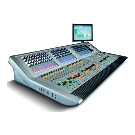
Vista 1 Digital Mixing System Desk operation Fader Bay Control Bay The desk consists of two types of bays: From one to two fader bays (ten faders each), and one control bay (ten faders plus two ‘grand master’ faders). For compactness, two fader bays are combined in a single fader bay module, as shown above. -
Page 55: Vistonics ® Operation / Local Views
Vista 1 Digital Mixing System 2.2.1 Vistonics operation / local Views ® Vistonics Rotary Control Area Each rotary control is grouped with a key to form a control element. These control elements are sometimes used in a channel-related manner, dedicating four of the control elements to each channel strip;... - Page 56 Vista 1 Digital Mixing System VIEW: CHANNEL Brings up a view of all control elements of this channel besides dynamics, equalizer, and pan, covering the whole Vistonics rotary control area. VIEW: MISC View Selection of DYNAMICS, EQ, and PAN Controls Brings up a view of selected control elements out of dynamics, equalizer, and pan, covering the whole Vistonics rotary control area.
-
Page 57: Fader Area
Vista 1 Digital Mixing System 2.2.2 fader area USR 1 Key for programmable user- or application-specific functions (such as fader start, fader ramps (audio-follows-video), switching to an alternate n-x output signal, user specific functions etc.). MUTE Mutes the corresponding channel. The MUTE LED indicates when he channel is muted by a SOLO IN PLACE function or by a mute group. -
Page 58: Channel Meters
Vista 1 Digital Mixing System 2.2.2.1 Channel Meters Each channel strip hosts a tri-coloured two-channel LED bargraph meter, indicating various levels of the corresponding channel. The lower part of the meter is reserved to show gain reduction in case compressor/limiter (right side) or expander/gate (left side) is active. -
Page 59: Channel Selection
Vista 1 Digital Mixing System 2.2.2.2 Channel selection MULTI SEL Used to make multiple selections; acts similar as the ‘Ctrl’ key on a PC key- board. LINK ALL Links all channels of one type together (‘Super Gang’) mainly for setup purposes. -
Page 60: Global Views
Vista 1 Digital Mixing System 2.2.3 Global Views The GLOBAL VIEW keys allow changing the view on the fader bays or across the whole console if FOLLOW is active on control bay. If the control bay is not in FOLLOW mode, these keys will only change the views on the two fader bays. -
Page 61: Central Channel Processing Keys
Vista 1 Digital Mixing System GLOBAL VIEW: LABEL TYPE Changes the label type of the second line in the generic display area to show: • Device label (also referred to as user label) • Fixed label (shows the input channel’s number) ... - Page 62 Vista 1 Digital Mixing System HI CUT LO CUT DELAY INS COMP / LIMIT EXP / GATE EQ PAN Audio processing functions on/off; if lit, the corresponding audio function is activated. If dark, the function is bypassed. For more details about functions...
- Page 63 Vista 1 Digital Mixing System A (Copy/Paste All) As above, but includes all functions of a channel at the same time. This includes input gains, AUX, fader and bus assign. This function ‘clones’ the whole channel. Hint for console setup: Set one channel to the desired status, including bus assignment etc., create a ‘super gang’...
-
Page 64: Control Bay Details
Vista 1 Digital Mixing System 2.2.5 Control Bay Details 2.2.5.1 system/tB/headphones STBY Indicates that AC power is connected to the desk. Flashes, if redundant power supplies are fitted and power is lost on one of them. MAIN ON Indicates that the power for the control system is ok. -
Page 65: Assignable Meters And Meter Selection
Vista 1 Digital Mixing System HEADPHONES Adjusts the headphones level. The headphone signal is the same as the one listened to in the control room. However, whenever a PFL is active, the signal gets fed into the headphone with higher priority. -
Page 66: Control Room Monitoring
Vista 1 Digital Mixing System 2.2.5.3 Control room Monitoring MONO, L-R, LCRS, 5.1 Selects the control room monitoring format. The monitoring section hosts a 5.1-to-two-channel downmixer. When L-R is active and the selected monitor- ing source delivers a 5.1 signal, the six channels get mixed down to two chan- nels automatically. - Page 67 Vista 1 Digital Mixing System normally shows the control room listening level. Turn the knob below the display for adjustment of solo offset level. If any of the PLF or SOLO keys on the console is active (even if it is currently not visible on the surface), this key will be lit.
- Page 68 Vista 1 Digital Mixing System SIP SAFE Pressing this key enters setup mode for editing the channels that should be safe from muting when activating SOLO IN PLACE on any other channel; by default, all master channels are safe from muting when SOLO IN PLACE is active.
-
Page 69: Studio Monitoring
Vista 1 Digital Mixing System 2.2.5.4 studio Monitoring Select (STUDIO) A/B..to access this Area A / B RED LIGHT, SIG 1 (Ready), SIG 2 (Call), TALK These functions can directly be activated for two different studios. The keys may light automatically if the function has been activated by using GPI (gen- eral purpose inputs). -
Page 70: Monitoring Source Selection
Vista 1 Digital Mixing System 2.2.5.5 Monitoring source selection POPUP POPUP POPUP POPUP LINE DESK DESK MAIN MAIN First select the target to be changed: CR (control room), STUDIO A, or STUDIO B. Then select the appropriate source key. All keys are fully user- definable by using the monitoring setup dialog in the Graphical Controller application (accessible to system administrators only). -
Page 71: Custom Panel (Gpio Keys)
Vista 1 Digital Mixing System 2.2.5.6 Custom panel (GpIo keys) This area contains keys for controlling the general purpose control outputs (GPO). The control inputs (GPI) can be used for illuminating the keys. The factory default configuration is GPO 1-12 on the CUSTOM PANEL GPIO socket... -
Page 72: Talkback Control
Vista 1 Digital Mixing System 2.2.5.8 talkback Control TALKBACK Whenever TALK is pressed, the signal from the talkback microphone input is fed to the corresponding group. The talkback input usually is microphone input no. 32. It is pre-configured but not activated, refer to chapter 2.1.5. -
Page 73: Control Room
Vista 1 Digital Mixing System Talkback and Signaling Block Diagram Using Desk-Internal GPIO Studio A Studio B e.g. Speaker e.g. Speaker Studio Monitor A Studio Monitor B CR Monitor Control Room GPO 1 GPO X GPO X GPO X GPI X... -
Page 74: Control And Mute Group Setup
SETUP: GROUPS Pressing this key will enter/exit control group and mute group mode. Vista 1 provides up to 16 mute groups. MUTE GROUPS M1...M8 have dedicated keys on the left side of the control bay. The additional mute groups M9...M16 may be operated using eight of the 16 monitoring source selectors. -
Page 75: Setting Up A Mute Group
Vista 1 Digital Mixing System 2.2.5.9.3 Setting up a Mute Group Press the SETUP: GROUPS key on the control bay. The mute group master keys (dedicated MUTE GROUPS M1...M8 keys, and, if defined, keys M9…M16 in the SOURCE SELECTOR area, see above) will be half-lit. -
Page 76: Off-Air Conference
Vista 1 Digital Mixing System 2.2.5.9.4 Off-Air Conference SETUP: CONF If the DSP configuration contains n-x buses, it is possible to setup an off- air conference between n–x owner channels. After pressing this key, all n-x owner channels become half-lit and members of a conference can be selected (full-lit). -
Page 77: Gc Shortcut Keys
Vista 1 Digital Mixing System 2.2.5.10 GC shortcut keys SNAPSHOT 1...4 A snapshot contains all audio settings including patching and labels. These keys allow four snapshots to be saved and recalled without making use of the Graphical Controller screen. • Making a snapshot: Press and hold MAKE SNAPSHOT, then press one of the SNAPSHOT 1...4 keys. -
Page 78: Cue List Keys
Vista 1 Digital Mixing System 2.2.5.11 Cue list keys These keys give direct access to the cue list on the control bay. They can be used to control various functions of the cue list and allow certain functions to be switched using a hardware key, while it remains possible to use the touchpad and operate these functions on the Graphical Controller screen: •... -
Page 79: Joystick
Vista 1 Digital Mixing System 2.2.5.12 Joystick Display Indicates the label of the channel currently assigned to the Joystick. Y axis lock X axis lock Lock the Y axis () or X axis () when moving the joystick. -
Page 80: Fader Page Navigator
Vista 1 Digital Mixing System 2.2.5.13 fader page navigator These keys allow changing the Control Bay faders to different pages. Each page may be scrolled by 10 faders to the left or right, allowing for a total of 120 channels to be displayed in the control bay. Any channel type may be placed on the Control Bay channel strips, including masters and input chan- nels. -
Page 81: Grand Master Faders
Vista 1 Digital Mixing System 2.2.5.14 Grand Master faders Vista 1’s control bay also hosts two ‘grand master’ faders. The user determines which two faders are the most important ones for him and to which he wants to have constant access. -
Page 82: Stereo Channel Fader Unfold On Grand Masters
Vista 1 Digital Mixing System 2.2.5.15 stereo Channel fader Unfold on Grand Masters From SW V5.3 onwards, an exceptional use is made of the Grand Master faders. The Grand Master faders can optionally be used to display and adjust L and R fader values from any stereo channel. - Page 83 Vista 1 Digital Mixing System As soon as the separate offset fader values differ from the main fader value, this offset is indicated with a small “L”or”R” icon in the label area. During this temporary action, the channels that are assigned to the Grand Master Strips in the Strip setup, are currently not shown and cannot be oper- ated for as long as the CHANNEL VIEW of a stereo channel is active.
-
Page 84: Output Views / Follow
Vista 1 Digital Mixing System 2.2.5.16 output Views / folloW Besides the monitoring and housekeeping functions the control bay hosts twelve faders and a Vistonics screen. The faders are independent from the rest of the console in terms of changing fader pages. - Page 85 Vista 1 Digital Mixing System Channel Label Channel Fader Level Real-Time Level Meter Channel Fader Control SOLO / PFL with Vistonics Rotary MUTE / TALK FOLLOW If this key is active, the view on the control bay Vistonics will follow the GLOBAL VIEW of the fader bay, indicating the same 4 parameters per channel strip belonging to each of the 10 faders below.
-
Page 86: Contribution Access
Vista 1 Digital Mixing System 2.2.5.17 Contribution access Very often it is useful to operate the console in ‘reverse’ way, coming from an output fader and operate the various input channels contributing to this output. By pressing one of the CONTRIB keys located above the faders the Vistonics rotaries will show all channel faders currently contributing to this master signal. -
Page 87: Spillzone
Vista 1 Digital Mixing System REDUCED (View) OFF All channels that may contribute are displayed. These are all channels that can be assigned to that specific output bus. This view allows assigning or de-assigning them from the master bus by using the corresponding Vistonics keys. - Page 88 Vista 1 Digital Mixing System ing, defines the direction of the arrow. The spilled channels will be lined up starting from the leftmost channel strip across one FaderBay. The spilled channels will be lined up starting from the leftmost channel strip across two FaderBays.
- Page 89 Vista 1 Digital Mixing System the show the normal StripSetup. Nested Spill If a spilled master has another master assigned to itself, this assigned master channel can spill its members in the same SpillZone by pressing its CONTRIB key. Example : Six input channels (Inp m 1 - Inp m 6) as well as one group channel (Grp st 1) are assigned to contribute to a master channel (Mst st1).
- Page 90 Vista 1 Digital Mixing System SpillZone after Step 2 Deactivation of Spill : Any of the following actions will immediately bring the desk back to show the normal StripSetup : • Pressing the CONTRIB key of any spilling master channel a second time.
-
Page 91: Follow Solo
Vista 1 Digital Mixing System 2.2.5.19 follow solo By clicking on the newly introduced Follow Solo button in the GC Ribbon tab Tools, category General , the Follow Solo Mode gets activated. This is a global setting which is valid for all titles and remains active until the Follow Solo button is clicked again, even if the Vista application had been closed and restarted in between. - Page 92 Vista 1 Digital Mixing System A master is released out of Follow Solo as soon one of the following criteria is met : • The PFL resp. SOLO key is pressed again. • The PFL resp. SOLO key of a different master channel is pressed.
-
Page 93: Fader Bay Details
Channel Control Rotary Control If an analog Studer Mic/Line preamp (either built-in or in a Studer Compact Stage Box) is connected, the analog gain will be controlled before the A/D converters. If not, the rotary control will adjust digital input gain. In any case, further control is available on the Vistonics module. - Page 94 Displaying Both Layers at the Same Time: If the second layer option is activated, Vista 1 may display the label and real time metering of both layers at the same time. In order to activate this label view, press LABEL TYPE several times until the label display area on the Vistonics screen shows the labels of both layers.
-
Page 95: Clipboard Libraries
Vista 1 Digital Mixing System 2.2.7 Clipboard libraries On the Vista console it is possible to save and load clipboards to/from the hard disk or a USB stick. Clipboard files can contain one or more audio functions (e.g. EQ only, Dynamics only, or a combination of EQ and Dynamics) from a channel, or even can save complete channel settings. -
Page 96: Clipboard Library Window
Vista 1 Digital Mixing System 2.2.7.1 Clipboard library Window The Clipboard Library window is automatically opened whenever a paste function is pending on the Vista console. In order to open the window manu- ally (e.g., to load the console clipboard with a saved value), select the corre- sponding icon from the toolbar or press the OPTIONS F4 key on the console. -
Page 97: Rename/Delete A Clipboard Library File
Vista 1 Digital Mixing System 5 Click on the (Copy/Paste) button of the desired function in order to acti- vate copying. The button will light, and all possible destination keys on the console surface will be half-lit. Shortcut: A double-click on the clipboard name in the list will activate copying of all contained audio values within that particular file directly. -
Page 98: Import A Clipboard File From Another Library
Vista 1 Digital Mixing System 2.2.7.8 Import a Clipboard file from another library 1 Select ‘Import Clipboard’ from the file menu. 2 Navigate to the desired library. 3 Open the desired .cpy file. It will automatically appear and be saved within the currently active library. -
Page 99: Jingle Player Operation
Vista 1 Digital Mixing System 2.2.9 Jingle player operation The integrated jingle player is a stereo playback-only device intended for up to eight different audio clips, such as station identifier jingles, applause etc., that are triggered from the eight keys shown above. - Page 100 Vista 1 Digital Mixing System Input/Strip Mapping The jingle player can be assigned to a channel strip in the same way as any other input. It can be selected and patched like an input source in the Graphi- cal Controller.
- Page 101 Vista 1 Digital Mixing System The eight Jingle buttons mirror the desk hardware jingle keys. Upon inser- tion of a USB stick, the valid jingle files are assigned to the Jingle buttons. A click on a button triggers playback of the corresponding audio file, the same way as the corresponding desk key would.
-
Page 102: Faderglow
Vista 1 Digital Mixing System 2.2.10 faderGlow ® The fader tracks (including the ones of the Grand Master faders) can be illu- minated in any of eight available colors, based on function or session context. This color is repeated on the meter screen for additional clarity. - Page 103 Vista 1 Digital Mixing System For all possible channel types - mono, stereo, 5.1 - the metering goes with it, as shown above. Priority was to have as large a bar graph meter as possible. The lower area is configurable for displaying different options, depending...
- Page 104 Vista 1 Digital Mixing System displayed by turning the white bargraph section (i.e., the segments above the headroom threshold) to red. The meter tap point can be selected from input, post fader and direct output level of the corresponding channel.
- Page 105 Vista 1 Digital Mixing System The control bay TFT metering is of multiple use. The VIEW keys together with Control Bay the (shift) key allow switching between different views. All VIEW keys are of the momentary/latching type. The FOLLOW key displays the metering that belongs to the channel assigned to the desk surface.
-
Page 106: Virtual Vista
Vista 1 Digital Mixing System 2.2.12 Virtual Vista ‘Virtual Vista’ is a Windows application that can be used both as online and offline editor. An indicator visible on all fader and control bay screens shows whether the editor is currently online (connected to a desk), or offline. -
Page 107: Screen Layout
The area to the left of the Vistonics screen area shows the global view selec- tion as well as central channel processing buttons (as used in Vista 1 and 5). Section navigation is at the bottom of this part. It will change depending on whether a fader bay or a control bay is currently selected. -
Page 108: Fader Bay View
Vista 1 Digital Mixing System 2.2.12.2 fader Bay View By clicking into the meter area of one of the fader bay icons (Faderbay 1...), the corresponding Vistonics view opens up. The upper part of the selected fader bay icon is highlighted in order to make clear which bay the operator is looking at. -
Page 109: Control Bay View
Vista 1 Digital Mixing System By clicking into the fader area of one of the fader bay icons (Faderbay 1...), the ten corresponding faders are shown instead of the Vistonics screen. The central fader on the right is then hidden. The lower part of the selected fader bay icon is highlighted –... - Page 110 Vista 1 Digital Mixing System By clicking into the fader area of the control bay icon in the desk overview area, the ten faders of the control bay are shown. At the right of the screen the two GRAND MASTER faders are displayed.
-
Page 111: Gc View
Vista 1 Digital Mixing System 2.2.12.4 GC View The GC general patch view opens after a single click on the GRAPHICAL CONTROLLER – SHOW button (at the bottom right of any of the fader and control bay windows), or by a click on... - Page 112 Vista 1 Digital Mixing System 2-72 Desk Operation SW V5.3 Document generated: 18.04.17...
- Page 113 Vista 1 Digital Mixing System CHAPTER 3 Vistonics Parameters ............................3 Introduction ................................3 View Changes ..............................3 3.2.1 Global View Change ............................. 3 3.2.2 Channel View Change ............................4 Global Views ..............................5 3.3.1 Input Parameters..............................5 3.3.2 Pre-Amp Remote Parameters ..........................8 3.3.3...
- Page 114 Vista 1 Digital Mixing System 3-2 Parameters SW V5.3 Document generated: 18.04.17...
-
Page 115: Vistonics Parameters
Vista 1 Digital Mixing System VisToniCs PARAmETERs introduction The desk can show different audio controls on the Vistonics™ screens. The controls differ in type of graphical viewing, shapes, and colors. If required, they are grouped together with frames in order to give the user maximum information without the need to read text on the display. -
Page 116: Channel View Change
Vista 1 Digital Mixing System 3.2.2 Channel View Change The views listed below can be activated in each channel strip. Then the cor- responding values of this particular channel are shown. • Dynamics (by touching the green dynamics view on the screen) • EQ (by touching the red EQ view on the screen) • Panning (by touching the yellow pan view on the screen) • Bus Assignment (by pressing VIEW: BUS ASN – as opposed to the GLOBAL... -
Page 117: Global Views
Vista 1 Digital Mixing System Global Views 3.3.1 input Parameters Press GLOBAL VIEW: INPUT GAIN. For input sources IN 1, IN 2, and GEN (selection with the hardware keys below the channel meters), an input control view is available. The number of functions available on Input or Output channels, as well as on mono or stereo channels, depends on the currently loaded configuration. - Page 118 Vista 1 Digital Mixing System Input Parameters for Mono Channels only: Phase Two positions are provided (select either with the key or the rotary): • NORM/Off, in phase (default setting). • REV/On, out-of-phase. Input Parameters for Mono and stereo Channels: GaIn Input gain can set in 1 dB steps from –24 dB (attenuation by 24 dB) to +24 dB.
- Page 119 Vista 1 Digital Mixing System If a channel contains the input balance function, a balance control will be available in the pan page. This balance control is actually set before the mono switch in the signal path, within the input section of the channel. Hence it is...
-
Page 120: Pre-Amp Remote Parameters
Vista 1 Digital Mixing System Format Input Channels ITU Output Channels L R C L F E Ls Rs Studer (SW before V4.0) L R C Ls Rs LFE L R C LFE Ls Rs Film L C R Ls Rs LFE 3.3.2... - Page 121 Vista 1 Digital Mixing System a InseRT on/off (Not supported by transformer-balanced microphone pre-amplifier cards A949.0447, as well as 16 channel HQ mic/line input modules). An analog insert point is made available by inserting an optional analog insert card. Its send output is always active at line level, and the return path may be activated by the corresponding switch on the console.
-
Page 122: Direct, Multi-Track And N-1 Output Parameters
Vista 1 Digital Mixing System 3.3.3 Direct, multi-Track and n–1 output Parameters Press GLOBAL VIEW: OUT n-1. This view allows controlling the level of the Direct, Multi-Track and the channel’s contribution (‘send’) to the N–1 bus(es). If the channel is assigned as a bus owner of an N–1 bus, the N–1 bus outputs is controlled from here as... -
Page 123: Mono Aux Parameters
Vista 1 Digital Mixing System 3.3.4 mono AUX Parameters Press one of the GLOBAL VIEW: AUX MONO keys. The mono AUX view provides selection of the AUX bus (ON/OFF), send level adjustment, and pre-/after-fader switching. From 5.1 surround channels, mono AUX sends are fed with an ITU-compatible mono down-mix. From... -
Page 124: Stereo Aux Parameters
Vista 1 Digital Mixing System 3.3.5 stereo AUX Parameters Press one of the GLOBAL VIEW: AUX STEREO keys. The stereo AUX view provides selection of the AUX bus (ON/OFF), send level adjustment, pre-/after-fader switching, and pan setting. From 5.1 sur- round channels, stereo AUX sends are fed with an ITU-compatible stereo down-mix. -
Page 125: Filter Parameters
Vista 1 Digital Mixing System 3.3.6 Filter Parameters Press GLOBAL VIEW: FILTER. This view enables the user to control the parameters of the hi- and low-cut filters. These filters are available on the channel-related EQ view as well, refer to chapter 3.4.1. -
Page 126: Delay And Insert Parameters
Vista 1 Digital Mixing System 3.3.7 Delay and insert Parameters Press GLOBAL VIEW: DLY-INS. This view enables the user to control the delay and insert parameters. Please note: The two sections are activated with the DELAY and INS hardware keys above the Vistonics section. - Page 127 Vista 1 Digital Mixing System Insert Parameters: The insert section provides selection and control of the insert point (INSERT ON/OFF) and the INSERT MIX function (ON/OFF), plus defining the dry/ wet mix ratio (INSERT MIX %). INSERT On/Off is selected with the INSERT hardware key above the Vistonics section. ‘On’...
-
Page 128: Dynamics Parameters
Vista 1 Digital Mixing System 3.3.8 Dynamics Parameters standard or Vintage dynamics? Since SW version 4.0 there is an alternative dynamics processing block available for mono and stereo channels. It is called ‘Vintage Dynamics’ and consists of a compressor that can be used together with an expander/noise- gate. - Page 129 Vista 1 Digital Mixing System Standard Dynamics Section (left): LIM ThRs Rotary The limiter threshold can be adjusted in 1 dB steps from 0 dB –48 dB . The limiter threshold corresponds to the output level. LIM on/off Individual limiter on/off control.
-
Page 130: Expander / Gate Parameters
Vista 1 Digital Mixing System 3.3.8.2 Expander / Gate Parameters Press GLOBAL VIEW: EXP GATE. This view enables the user to control the most important parameters of the dynamics section’s expander and gate parts. The complete parameter set is available on the channel-related dynamics view, refer to chapter 3.4.3. - Page 131 Vista 1 Digital Mixing System GaTe hyst on/off The gate hysteresis function provides an offset between the un-mute and mute thresholds. So the gate will remain open (un-muted) at a level slightly lower than the one required to open it in order to avoid effects such as chattering.
-
Page 132: Parametric Eq Parameters
Vista 1 Digital Mixing System 3.3.9 Parametric EQ Parameters Select a bay showing channels that have the parametric EQ configured. Press Press GLOBAL VIEW: EQ. If a channel has configured both the parametric and graphic EQs, its Vistonics icon indicates additional PAR and GEQ labels; its touch surface is split into a left (PAR) and a right (GEQ) part, as shown at the left. -
Page 133: Graphic Eq Parameters
Vista 1 Digital Mixing System 3.3.10 Graphic EQ Parameters There is no global view of the graphic EQ available, since the graphic EQ of one channel always uses up the complete Vistonics screen. For graphic EQ operation please refer to chapter 3.4.2. -
Page 134: Global View Of 5.1 Surround Input Channels
Vista 1 Digital Mixing System 3.3.12 Global View of 5.1 surround input Channels With the 5.1 surround input channels, the user has input, EQ, dynamics and panning sections completely designed for premixed 5.1-channel input sources. The main goal is that he can adjust the most important parameters directly with a touch on the Vistonics screen, without the need to ‘spilling’... -
Page 135: Global Bus Assignment View
Vista 1 Digital Mixing System 3.3.13 Global Bus Assignment View Press GLOBAL VIEW: BUS ASN (at the left-hand side of the fader bay). This is an On/Off key that can be activated in addition to other global view keys. The bus assignment overview will cover the EQ, dynamics and pan curves on the lower part of the TFT;... -
Page 136: Generic And Label Display Area
Vista 1 Digital Mixing System 3.3.14 Generic and Label Display Area Channel label display: The top line always indicates the inherited label (corre- sponds to the device label of the patched source) of each channel. The second line normally is set to device label display, but can be changed by pressing GLOBAL VIEW: LABEL TYPE. -
Page 137: Channel-Related Views
Vista 1 Digital Mixing System Channel-Related Views 3.4.1 Parametric EQ and Filter Parameters note Since SW V4.7 there is an additional 30-band graphic EQ available; both graphic and parametric EQs can be set up either for all or specific channels using the Vista Configuration Editor. - Page 138 Vista 1 Digital Mixing System q value Rotary The Q (bandwidth) can be set to values from 0.27 through 8.7, in 30 steps. For the HM and LM bands Q can be set only if ‘bell’ is selected. HM, high-mid frequency, and LM, low-mid frequency: Q = 0.27 through 8.7, in 30 steps.
-
Page 139: Graphic Eq Parameters
Vista 1 Digital Mixing System 3.4.2 Graphic EQ Parameters note Since SW V4.7 there is an additional 30-band graphic EQ available; both graphic and parametric EQs can be set up either for all or specific channels using the Vista Configuration Editor. - Page 140 Vista 1 Digital Mixing System GEQ to Faders For ease of operation, the graphic EQ may be switched over to 30 of the console faders for both indication and control the setting. On Vista consoles featuring FaderGlow the colour of the corresponding fader tracks will illumi- nate in red.
-
Page 141: Dynamics Parameters
Vista 1 Digital Mixing System 3.4.3 Dynamics Parameters 3.4.3.1 standard Dynamics Limiter Parameters: LIM on/off Limiter on/off. LIM ThRs Rotary The limiter threshold (= output level) can be adjusted in 1 dB steps from 0 dB –48 dB LIM ReL Rotary... - Page 142 Vista 1 Digital Mixing System Compressor Parameters: CMP on/off Compressor on/off. CMP ThRs Rotary The compressor threshold level can be adjusted in 1 dB steps from 0 dB –96 dB CMP ReL Rotary The compressor release time can be adjusted in 13 steps within a 10 ms to 10 s range (10 ms, 20 ms, 30 ms, 50 ms, 100 ms, 200 ms, 300 ms, 500 ms, 1 s, 2 s, 3 s, 5 s, and 10 s).
- Page 143 Vista 1 Digital Mixing System Gate Parameters: GaTe on/off Gate on/off. GaTe ThRs Rotary The gate threshold level can be adjusted in 1 dB steps from 0 dB –96 dB GaTe ReL Rotary The gate release time can be adjusted in 13 steps within a 10 ms through 10 s range (10 ms, 20 ms, 30 ms, 50 ms, 100 ms, 200 ms, 300 ms, 500 ms, 1 s, 2 s, 3 s, 5 s, and 10 s).
- Page 144 Vista 1 Digital Mixing System sC hI CUT/Lo CUT Rotary Both side-chain high- and low-cut filters feature cut-off frequencies continu- ously adjustable between 20 Hz and 20 kHz. MKUP GaIn auto on/off ‘auto on’ automatically compensates a compressor level loss. ‘auto off’ acti- vates the manual MKUP GAIN rotary control.
-
Page 145: Standard Dynamics For 5.1 Surround Channels
Vista 1 Digital Mixing System 3.4.3.2 standard Dynamics for 5.1 surround Channels Touch the green Vistonics dynamics field. This view is the same as with mono or stereo channels with one exception, refer to the screenshot below. Please note that the dynamics settings applied here will be valid for all surround signal legs except the LFE. - Page 146 Vista 1 Digital Mixing System Four different possibilities are available: All signal legs (L, R, C, Ls, Rs) are part of the sidechain link. Only the L, R, Ls and Rs signal legs are part of the sidechain link. Only the L, R and C signal legs are part of the sidechain link.
-
Page 147: Vintage Dynamics
Vista 1 Digital Mixing System 3.4.3.3 Vintage Dynamics Please note that the vintage dynamics section is available for mono and stereo channels only. The main differences between the vintage and standard dynamics sections is that the vintage dynamics are intended as an effect rather than being trans- parent. - Page 148 Vista 1 Digital Mixing System CMP MIX on/off ‘on’ activates the CMP MIX function; ‘off’ selects the compressed signal only. When the CMP MIX function is set to ‘on’, the ratio of the dry (original) to the wet (compressed) signal depends on the selected mix ratio. In other words, mixing between the original and the compressed signals is possible.
-
Page 149: Panning Parameters
Vista 1 Digital Mixing System 3.4.4 Panning Parameters There are several panning options available. These range from a simple mono-to-left/right pan over a stereo direction pan with width control to the sophisticated family of Virtual Surround Panning (VSP) modules. Left/Right and VSP functions are available for mono input, group, multi-track input, and multi-track monitor channels. - Page 150 Vista 1 Digital Mixing System LR Pan for stereo Channels The PAN ON/OFF and PAN functions are extended to enable working with either standard (L/R) stereo or with MS (mono/side) signals. In addition, features are available to increase the stereo image manipulation possibilities, such as • Input direction or...
-
Page 151: Amplitude Panning Parameters
Vista 1 Digital Mixing System 3.4.4.1 Amplitude Panning Parameters Mono Channels: Stereo Channels: LR Panning Parameters for Mono Channels: Mono channel LR PAN has only one panning function: left/right panning. It is useful for left/right panning to stereo master or group busses, or for odd/ even panning to group or multi-track busses. - Page 152 Vista 1 Digital Mixing System InP dIR / BaL Selection from two input functions: INP BAL or INP DIR. InP dIR / InP BaL Rotary The INP DIR function is used to control the direction of a stereo input signal.
-
Page 153: Upmix Panner Parameters (For Stereo Channels Only)
Vista 1 Digital Mixing System 3.4.4.2 Upmix Panner Parameters (for stereo Channels only) Still a significant number of stereo sources is used for a typical surround production, so these need to be brought into the 5.1-channel format. The upmix panner is a way to pan stereo signals to a surround mix, providing the possibility to ‘unwrap’... -
Page 154: Multi-Format Panning Parameters
Vista 1 Digital Mixing System 3.4.4.3 multi-Format Panning Parameters Surround panning consists of two panning algorithms: Multi-format panning, and VSP (Virtual Surround Panning). These support a variety of surround formats and applications; in all these modes, an LFE (Low Frequency Effects) control is available. - Page 155 Vista 1 Digital Mixing System FoRMaT Rotary This serves as the format selector in all multi-format panning modes. The fol- lowing selections are possible: L-R, LCR, LCRS, 5.1, EX, and 7.1. Depend- ing on this selection, the actually required parameters are displayed.
-
Page 156: Vsp Panning Parameters
Vista 1 Digital Mixing System 3.4.4.4 VsP Panning Parameters Please note that the controls within the left part of the screenshot below are identical with the ones in chapter 3.4.4.2 – for details, please refer to the description in that chapter. - Page 157 Vista 1 Digital Mixing System • oRTF – An idealized version of the common cardioid microphone setup according to angles and distances used for stereo miking. A more accurate sound field is created through the manipulation of both amplitude and time differences.
-
Page 158: Panning Parameters For 5.1 Surround Channels
Vista 1 Digital Mixing System 3.4.4.5 Panning Parameters for 5.1 surround Channels Touch the yellow Vistonics pan field. General PAN on/off is selected with the PAN hardware key above the Vistonics section. CenT LeVeL Center level control from MUTE (i.e. –∞ dB) to +10 dB. - Page 159 Vista 1 Digital Mixing System CenTeR on/off On/off selector for center channel use. CenTeR Center channel percentage control; 0% = no center channel use (phantom center), 100% = center channel fully active. FRonT WIdTh on/off Switches the FRONT WIDTH function on/off.
-
Page 160: Microphone Simulation Tool (Mst) - User Pan Mode
Vista 1 Digital Mixing System 3.4.4.6 microphone simulation Tool (msT) – User Pan mode As a further sophistication of the VSP system, a Microphone Simulation Tool (MST) has been created. This allows the mix engineer to create his/her own multi-channel panning law, by simulating the placement of microphones in a virtual space. - Page 161 Vista 1 Digital Mixing System Here are the placements for some of the Panner Mode presets: oRTF (With surrounds) The amplitudes vary due to the directionality of the microphones, while time delay is varied based on the distances between the microphones (each of them feeding a speaker).
- Page 162 This is an exciting and functional tool that the mix engineer now has exclusively with the use of the VSP panning system within the Studer D950 or Vista consoles. 3-50 Parameters SW V5.3...
-
Page 163: Vistamix (Vmx)
3.4.5 Vistamix (VmX) Basics Studer VistaMix is an automatic mix algorithm based on gain sharing, intro- duced with SW V4.9. VistaMix processing comes in very handy in multi- microphone situations, such as round-table discussions or unscripted games shows, in which indirect voice and early reflection-spill negatively affects the summed mix. - Page 164 Vista 1 Digital Mixing System Several instances of both mono and stereo VistaMix channels may be config- ured in a single DSP configuration. If you wish VistaMix channels to slave or re-enter, you will need to add the appropriate bus links in the configuration tool’s Channel Bus page.
- Page 165 Vista 1 Digital Mixing System VistaMix Master Channel Master channels will appear in cyan in the strip assign page and may be assigned to the faders in the normal way. The Vistonics view of the VMX bus parameters is opened by touching the Vistonics PAN icon of the desired bus.
- Page 166 Vista 1 Digital Mixing System Response Time The response can be set from 20 ms up to 4 s. Recommended setting is 50 ms but the engineer’s ears have to decide. The response time cannot be compared with release and attack times of dynamic processes. This time sets how fast the crossfades between the calculated gain values are executed and how fast VistaMix is reacting on the occurring changes of the signals.
-
Page 167: Channel View In General
Vista 1 Digital Mixing System 3.4.6 Channel View in general VIEW: CHANNEL Pressing brings up an overview for the selected channel, covering the whole Vistonics TFT. All parameters of a channel except for Dynamics, EQ, and Pan are shown in the rotary section. -
Page 168: Channel View - Stereo Channel
Vista 1 Digital Mixing System 3.4.7 Channel View - stereo Channel From SW V5.3 onwards, an Input Gain Unfold can be found on stereo chan- nels. This functionality allows the operator to have separate input gain levels on both legs of a stereo channel. As with the 5.1 channels, this feature can be found in the CHANNEL VIEW. - Page 169 Vista 1 Digital Mixing System When using the fold button to go back to the normal CHANNEL VIEW, the individual input gains are kept and the main input gain control will then just apply an offset to the individual gains.
-
Page 170: Channel View - 5.1 Surround Channel
Vista 1 Digital Mixing System 3.4.8 Channel View - 5.1 surround Channel Pressing VIEW: CHANNEL brings up an overview of the selected channel, covering the whole Vistonics TFT. All available parameters are shown in the rotary section, except for dynamics, EQ, and panning. Only visible parame- ters are available for adjustment. - Page 171 Vista 1 Digital Mixing System When using the fold button to go back to the normal CHANNEL VIEW, the trimmed input gains are kept and the main input gain control will then just apply an offset to the individual gains. Any trimmed input legs are then listed underneath the dB value.
- Page 172 Vista 1 Digital Mixing System Upon touching one of these fields (e.g. the green ‘Center’ dynamics field) the display changes to the individual dynamics setting of the ‘Inp x 1’ 5.1 input’s center channel. 3-60 Parameters SW V5.3 Document generated: 18.04.17...
- Page 173 Vista 1 Digital Mixing System After the individual setting has been made, pressing VIEW: CHANNEL again switches back to the standard channel view. In our case (where the front and LFE channels of Inp x 1 have individual dynamics settings), the dynamics...
-
Page 174: Misc View (Miscellaneous Parameters)
Vista 1 Digital Mixing System 3.4.9 misc View (miscellaneous Parameters) Pressing VIEW: MISC brings up an overview for the channel selected with the LINK / SEL key, covering the whole Vistonics TFT. The most important parameters of a channel’s dynamics, EQ, and pan sections are shown in the rotary section. -
Page 175: Bus Assignment View
Vista 1 Digital Mixing System 3.4.10 Bus Assignment View When pressing VIEW: BUS ASN, the display changes to the bus assign window of the channel selected with the LINK / SEL key. Only busses are shown here to which the current channel can be assigned. - Page 176 Vista 1 Digital Mixing System 3-64 Parameters SW V5.3 Document generated: 18.04.17...
- Page 177 Vista 1 Digital Mixing System CHAPTER 4 Graphical Controller Operation ........................5 Introduction ................................5 The GC Screen ..............................6 4.2.1 The View Button ..............................7 4.2.2 The Quick Access Bar ............................7 4.2.3 The Ribbon Style Selector ............................ 8 Graphical Controller Basics ..........................9 4.3.1...
- Page 178 Moving Already Assigned DSP Channels to Other Channel Strips ................85 4.4.6.1.4 Useful Information ...............................86 4.4.6.1.5 Labels in Strip Setup ..............................86 4.4.6.1.6 Metering (the TFT Meterbridge is optional for the 32 fader Vista 1) ................88 4.4.6.1.7 FaderGlow ..................................90 4.4.7 Clipboard Libraries ............................. 91 4.4.7.1 Clipboard Library Window ............................92...
- Page 179 Vista 1 Digital Mixing System 4.6.1 The Tools Ribbon Tab ............................105 4.6.1.1 General ...................................105 4.6.1.1.1 Clipboard ..................................105 4.6.1.1.2 Follow Solo ................................105 4.6.1.1.3 Offline Conference ..............................105 4.6.1.1.4 Show Virtual ................................108 4.6.1.1.5 Machine Control.................................108 4.6.1.2 Setups ..................................109 4.6.1.2.1 FX Engine ..................................109 4.6.1.2.2...
- Page 180 Vista 1 Digital Mixing System 4.7.18 Snapshot: Output Snapshot Isolation ........................ 151 Fifth Level: The Surveyor ..........................152 4-4 GC Operation SW V5.3 Document generated: 18.04.17...
-
Page 181: Graphical Controller Operation
Vista sessions, the user basically needs to start only one application program: D950SYSTEM.EXE. The D950SYSTEM.EXE is represented by the Studer Vista shortcut icon on the GC monitor screen: The Vista software runs under Windows. All files used by Vista and all files produced by the user (snapshots, mixes, etc.) are fully compatible with the... -
Page 182: The Gc Screen
Vista 1 Digital Mixing System Because the graphical controller’s user interface can be configured to suit the individual needs of specific users, all the graphics shown in this operating instructions manual may differ slightly from what you will see on the GC display of your Vista digital console. -
Page 183: The View Button
Vista 1 Digital Mixing System 4.2.1 The View Button When clicking on the View button, the icons of the five main GC pages appear in a drop-down list. Choosing the desired GC page not only opens this page, but also changes the Ribbon tab to the category that contains the menu items for this GC page. -
Page 184: The Ribbon Style Selector
Vista 1 Digital Mixing System By choosing the desired menu item (also called ‹Commands›) and clicking on the Add button will add that specific menu item to the Quick Access Toolbar. The Reset button will bring you back to the state that the Quick Access Toolbar had before you started to modify it. -
Page 185: Graphical Controller Basics
Vista 1 Digital Mixing System Graphical Controller Basics This chapter describes the basic concepts of the work with the graphical controller (GC). 4.3.1 Sources and Targets Generally, all audio signals available to the Vista can be divided into Sources and Targets. These names are used rather than ‘Input’, ‘Out put’, etc., in order to avoid any confusion about where the audio signal comes from and goes to. -
Page 186: Pre-Defined Configurations
Vista 1 Digital Mixing System 4.3.2 Pre-defined Configurations Vista 1 offers five different configurations to select from: Vista 1 Mono Has a large number of mono inputs that can be mixed to two stereo masters. Vista 1 Stereo Comes with a good blend of necessary channels for a stereo production. Mono groups and stereo masters are provided, as well as mix-minus busses. -
Page 187: Labels
Vista 1 Digital Mixing System 4.3.3 labels Labels are used extensively within the system to define objects, such as audio sources, channel names, etc., and to visualize these objects in various windows within the GC. Please note that all labels are saved within snapshots and presets, together with all audio settings. -
Page 188: First Level: Main Gc Pages
Vista 1 Digital Mixing System First level: Main GC Pages There are five main graphical controller pages, each of which deals with a different operating part of the Vista system: • General Patch page • Channel Patch page • Snapshot page • Cue List page • Strip Setup page These main pages can be accessed in three different ways: • From the View button, by clicking on the appropriate icon:... -
Page 189: Working With Multiple
Vista 1 Digital Mixing System 4.4.1 Working with Multiple Pages Working with muliple pages is not possible with the new Ribbon style menu 4.4.2 The General Patch The GC General Patch page can be accessed in three different ways: • From the View button, by clicking on the appropriate icon • Using the Quick Access Toolbar icons, by clicking on the appropriate icon... - Page 190 Vista 1 Digital Mixing System The General Patch consists of: • A Targets list (the lower horizontal, or x axis), equivalent to the lower jack row in a patch bay • A Sources list (the left-hand vertical or y axis), equivalent to the upper jack row in a patch bay • The X-Y field, where the cross-point icons enable interrogation and editing of cross-point connections • The Source- and Target Patch Group selection • The Page Patch Group selection (navigates both, Source- and Target lists) • The Source- and Target selection bar, which allows choosing a crosspoint • Viewing selections which allow sorting of the Sources and Targets Lists by label type • The Fixed/User Label displays for the selected Source/Target...
-
Page 191: General Patch Navigation
Vista 1 Digital Mixing System 4.4.2.1 General Patch navigation 4.4.2.1.1 Navigating the Sources/Targets List The audio sources list (located on the Y axis) and the targets list (on the X axis) allow the user to find and select a Source/Target pair, and to make or clear a required cross-point connection. -
Page 192: Other Navigation Methods
Vista 1 Digital Mixing System Select the Patch Page 4.4.2.1.2 Other Navigation Methods Using of Color for Navigation: Color is used in the Sources and Targets lists to give a clear indication and overview of the sources and targets which have connections patched. If a Source is connected to a Target or multiple targets, the Source label in the Sources List will be highlighted by a color. -
Page 193: What Patch Groups Are There
Vista 1 Digital Mixing System 4.4.2.1.3 What Patch Groups are There? There are different, fixed Patch Groups for each of the Sources and Targets Patch Group selectors : Sources: Targets: Each Patch Group contains a number of Sources or Targets, depending on the currently loaded configuration. -
Page 194: How To Deal With The Analog Interfacing
Vista 1 Digital Mixing System 4.4.2.2 How to Deal with the Analog interfacing? There is no difference between analog and digital interfacing. The respec- tive HQ mic/line input card or line output card incorporates the A/D or D/A converters and provides digital signals to- and from the system. -
Page 195: Making And Clearing The Cross-Points
Vista 1 Digital Mixing System 4.4.2.4 Making and Clearing the Cross-Points The creation and updating of cross-points is simple. First, select the source and target; the selection bars have to be crossed to form an X-Y pair. There are two ways of making or breaking a cross-point connection: • By double-clicking the left touch pad button, while the cursor is positioned... - Page 196 Vista 1 Digital Mixing System Stereo Source – Mono Target Icon Indicates Connection Type Left to Mono Right to Mono Protected Connection Clear Connection Mono Source – Stereo Target Icon Indicates Connection Type Mono to Both Left & Right Mono to Left (Leave Right as is)
- Page 197 Vista 1 Digital Mixing System Tip A feature is available for fast diagonal patching of multiple Sources to mul- tiple Targets. The example below shows this feature used in practice. • By keeping the left touch pad button pressed while dragging the pointer across a region in the General Patch view, multiple connections can be selected now.
-
Page 198: Editing The User Labels In The General Patch
Vista 1 Digital Mixing System Connection Protection It is also possible to protect a certain connection from accidental change both by the user or by recalling a snapshot. Double-clicking on a connection selects the padlock item to lock the connec- tion. -
Page 199: Sorting Options
Vista 1 Digital Mixing System 4.4.2.5.1 Sorting Options There are two options for sorting the display of the Sources and Targets in the General Patch Lists. This sorting is independent of which label type is being displayed due to the global label mode selection. -
Page 200: Working With Labels
Vista 1 Digital Mixing System 4.4.2.6 Working with labels For a detailed description of different label types, please refer to chapter 4.3.3. The most important aspect of any audio patching system is its labeling. Clear labeling allows fast navigation and fault-free patching. -
Page 201: Automatic Label Propagation
Vista 1 Digital Mixing System 4.4.2.6.1 Automatic Label Propagation The philosophy on Vista consoles concerning labeling is not to name any labels within channels, but to name patch sources in the General Patch, let- ting the system propagate them to the connected channels. Specifically, we are talking about two kinds of labels which will be propagated in this way: Device labels (technical labels), and User labels (session labels, e.g. -
Page 202: What Are Device Labels
Vista 1 Digital Mixing System This may look as follows: Large Label = Source User Label Small Label Toggles to Show: • Device Label • Fixed Channel Label Note In the Strip Setup window it is possible to display either the session labels (standard) or the device labels, depending on the option selected in the lower right corner of the window. -
Page 203: How To Activate The Device Label Functionality
Vista 1 Digital Mixing System 4.4.2.8 How to Activate the Device label Functionality In order to activate the automatic import of your device labels from the device label file, two conditions must be met: • There must be a preset file named ‘ ’ matching the __DeviceLabels.pre currently loaded configuration and holding your device label names. -
Page 204: Automatic Generation Of Intelligent Fixed Labels
Audio coming through the D21m I/O components is reaching the core over Studer’s proprietary HD (high density) link in case of the SCoreLive. This link is present between the local hub(s) and the DSP core. Each link may carry up to 96 audio channels. - Page 205 Vista 1 Digital Mixing System general patch, the software is able to give more intelligent names to the input and output ports shown in the general patch. You will then see frame numbers as well as card types and channel numbers within each card. This generation is automatically active whenever the D21m I/O system is present and the hub frame is connected to the console via a serial link.
-
Page 206: Channel Patch
Vista 1 Digital Mixing System 4.4.3 Channel Patch The Channel Patch page of the graphical controller can be called up in three different ways: • From the View button, by clicking on the appropriate icon • Using the Quick Access Toolbar icons, by clicking on the appropriate icon;... -
Page 207: Using The Channel Patch For Patching Audio
Vista 1 Digital Mixing System Essentially, the Channel Patch provides a block diagram of the selected chan- nel’s audio path. All channel types can be selected. From the Channel Patch, you can: • View General Patch connections to and from the selected channel; • Directly access the channel’s patch points in the General Patch; • View channel’s DSP processing blocks; • Set the order of DSP processing blocks in the selected channel’s audio path;... -
Page 208: Setting The Order Of Dsp Processing Blocks
Vista 1 Digital Mixing System 4.4.3.2 Setting the order of DSP Processing Blocks The following processing blocks (if available in the currently selected con- figuration) can be placed individually at different locations along the Audio Path of the channels: • EQ;... -
Page 209: Set The Metering And Direct Out Source Point
Vista 1 Digital Mixing System 4.4.3.5 Set the Metering and Direct out Source Point Set Metering Source Point: To set the Metering Source point in the selected channel’s audio path, click on one of the three Meter boxes. The channel meter will now be sourced from the selected point in the signal path. -
Page 210: Setup & Activate The Dynamics Sidechain Link
Vista 1 Digital Mixing System 4.4.3.7 Setup & Activate the Dynamics Sidechain link The effect of a Dynamics Sidechain Link, if activated, is identical to any item of outboard gear set to Link or Stereo mode. This function is used to control between two and eight Dynamics Processors inserted into up to eight different channels. - Page 211 Vista 1 Digital Mixing System Sidechain Link Setup: Click on the Sidechain Link Setup button to bring up the Sidechain Link editor screen, which allows selecting available links and adding/removing of channels to/from the links. Select Available Sidechain Links View the Selected Link Numbers...
-
Page 212: Fader Ramp Control ('Audio Follows Video')
Vista 1 Digital Mixing System 4.4.3.8 Fader Ramp Control (‘Audio Follows Video’) Faders of all console channels can be externally controlled. When using this feature, the console operator determines the Fader Open/Close values, as well as the fade in/out speed. Various triggers are available in order to activate the fade. -
Page 213: Snapshot Page
Vista 1 Digital Mixing System closed’ position on one of the two and vice versa allows using one GPI to control opening and closing of different channels at the same time. Speed ON: Determines the time used for fading in the corresponding channel. -
Page 214: Snapshots
Vista 1 Digital Mixing System A snapshot or preset will save: • All audio settings: Fader levels, auxiliary settings, dynamics, delays, input selectors, etc. • Order of channel processing blocks; • Direct output and meter source points; • Bus assignments; • All labels; • All patch cross-point connections; • Channel and other links; • N–1/mix-minus assignments. Tip Snapshots and presets always save every control and switch setting for the entire console. - Page 215 Vista 1 Digital Mixing System Now You Can: Recall a Snapshot • Select a snapshot from the List, and • click on the Recall button, or • simply double-click on the snapshot you wish to recall. The snapshot that was recalled last is marked with a small triangle. If the ‘Recall Confirm’ option in the Snapshot tab, category Options is checked, there will be a pop-up dialog requiring confirmation of snapshot Recall.
- Page 216 Vista 1 Digital Mixing System Note: Once a snapshot or preset is applied, the existing parameter settings are replaced by those contained within the snapshot or preset. If the previous settings had not been saved, there is an Undo button available, in order to go back to the last settings before recalling the snapshot or preset.
- Page 217 Vista 1 Digital Mixing System Delete Snapshot(s) • Select a snapshot from the List, or • Select any number of snapshots from the List using the familiar Windows multiple-selection techniques (press Shift and select the first and the last snapshot with the touch pad pointer, or press Ctrl and select whichever you desire with the touch pad pointer). A click on Delete will bring up a window to confirm the deletion.
-
Page 218: Multiple Snapshots
Vista 1 Digital Mixing System 4.4.4.2 Multiple Snapshots Updating Multiple Snapshots Very often, certain parameters should be overwritten in multiple snapshots. It may be important that only certain parameters are overwritten and others are left as they are in the individual snapshots. In order to achieve this, place those parameters into ‘Isolate’... - Page 219 Vista 1 Digital Mixing System Example 2 Goal The value of channel 3 should be reduced by 4 dB on ‘snapshot #1’, ‘snapshot #3’, and ‘snapshot #5’. These snapshots currently contain the following fader values: ‘snapshot #1’: 0 dB; ‘snapshot #3’: –5 dB; ‘snapshot #5’: –10 dB.
-
Page 220: Snapshot Crossfading
Vista 1 Digital Mixing System 4.4.4.3 Snapshot Crossfading In the Theatre CueList, it is possible to define a crossfade time for each cue - and therefore a crossfade time can be applied to a snapshot. This is done by simply clicking on the crossfade time and scroll your touch pad up or down. -
Page 221: Additional Snapshot Functionality
Vista 1 Digital Mixing System 4.4.4.4 Additional Snapshot Functionality In addition to the dedicated MAKE SNAPSHOT hardware key, there are four SNAPSHOT 1...4 keys for saving and recalling four individual snapshots on these keys. To save a snapshot onto one of the 4 keys, push and hold down the MAKE Assign a Snapshot to a Key: SNAPSHOT key, then hit the key you would like it to be saved on. -
Page 222: Partial Snapshots
Vista 1 Digital Mixing System Snapshot Preview: By clicking on the PREVIEW button, the console enters this mode. Regardless of which snapshot the user selects, pink elements within all Vistonics elements will show any difference between the current console settings and the settings within the previewed snapshot. - Page 223 Vista 1 Digital Mixing System If no gang is present, the whole console settings will be saved in a full snaps- hot. If the ‘New snapshots include:’ setting is set to ‘No Mask’, there will always be made a full snapshot, regardless of a gang being present or not. It is also possible to set the partial snapshot to ‘Active snapshot Filter’.
-
Page 224: Typical Applications
Vista 1 Digital Mixing System Next to each snapshot there is an Edit link at the very right of the snapshot list. By clicking this button, you will put the console into the ‘partial snapshot filter edit’ mode. Then you will see the same edit dialog box on the screen as when editing the snapshot filter. -
Page 225: Snapshot Filtering (Static Automation)
Vista 1 Digital Mixing System 4.4.4.7 Snapshot Filtering (Static Automation) At the time of recalling a snapshot, there might be a filter active, leaving some console settings unchanged upon recall of any snapshot. Each console parameter can therefore be in one of the following states: • Isolate ( = part of the filter); this parameter will not be influenced by... - Page 226 Vista 1 Digital Mixing System This window allows adding a whole group of parameters to your snapshot filter. Either select one of the four groups on top, or one of the listed busses. Audio Settings: Will add all channel processing functions to your snapshot filter.
-
Page 227: Presets
Vista 1 Digital Mixing System De-activating Snapshot Filters It is possible to de-activate an existing filter in order to re-activate it at a later point. Click on the corresponding icon in the toolbar to activate/de-activate the current snapshot filter. If the snapshot filter is de-activated, the icon for entering the snapshot filter edit mode is grayed-out and not accessible. -
Page 228: Default Settings
Vista 1 Digital Mixing System 4.4.4.9 Default Settings In the preset List, there is always one line labeled defaultSettings. This is a preset that is automatically generated for every Session Configuration, but no file will be found in the corresponding Session Configuration directory (as would be the case for other presets). -
Page 229: Cue List / Theatre Cue List
Vista 1 Digital Mixing System 4.4.5 Cue list / Theatre Cue list Two different cue list functionalities are available that allow sorting snaps- hots and attaching MIDI, HiQNet and other events to each one of them. Each title can contain only one single cue list. It can be controlled from external controllers using MIDI. - Page 230 Vista 1 Digital Mixing System at any time along with the TC stamp. The cues in the cue list are automatically sorted by increasing TC. If you make a new cue, it will be inserted into the list according to its TC stamp.
- Page 231 Vista 1 Digital Mixing System Edit Opens an edit window that allows changes to be made to the name and the timecode stamp of a selected cue from the cue list. Delete Opens an edit window that allows one or more cues to be deleted from the list.
-
Page 232: Theatre Cue List
Vista 1 Digital Mixing System 4.4.5.2 Theatre Cue list In order to activate the ‘theatre cue list’ functionality, enter the Ribbon tab Snapshot, category Options, opening the “Snapshot Automation Options” menu and tick the Enable Theatre Cue List item (the further menu options... -
Page 233: Cross-Fading Between Cues
Vista 1 Digital Mixing System event. A click on the Library Entries button opens the cue actor overview window that gives a comprehensive overview of all library events. At the bottom of the theatre cue list window, the name of the current cue (and snapshot, if appropriate) is indicated in large characters so that it may be clearly read even from a certain distance. -
Page 234: Organizing Events
Vista 1 Digital Mixing System After ten seconds faders 1…10 also have finished their cross-fade and are set to –20 dB. 4.4.5.2.2 Organizing Events It is possible to move events from one cue to a different one by using drag- and-drop. -
Page 235: Xfade Active
Vista 1 Digital Mixing System 4.4.5.2.6 XFade Active It may be useful to temporarily disable cue cross-fades (e.g., during rehear- sals). This can be done by un-checking this item. 4.4.5.2.7 Preview The snapshot/cue preview mode can be activated either by a hardware key or by clicking on the button located in the top right corner of the cue list window. -
Page 236: Event Types
Vista 1 Digital Mixing System 4.4.5.2.10 Event Types Library Events Cue-based theatre productions need a large number of parameter changes per channel, usually for a number of subsequent cues. Example: In scene 3, the character Jasbo Brown played by Daniel wears a wide-brimmed hat, changing the sound of his lavalier microphone due to reflections. - Page 237 Vista 1 Digital Mixing System MIDI/MMC Events The MIDI/MMC (MIDI machine control) event type can either be used for automatically sending MIDI commands if the symbol has been entered into the Events column (such as Program, Note On, Controller, MMC and Sysex), or for triggering the associated cue on arrival of the command if the symbol has been entered into the ...
- Page 238 Vista 1 Digital Mixing System Timed Events For a timed event, the time until the next cue is recalled as well as the number of the next recalled cue can be set. When clicking into the corresponding entry field, the recall time can also be adjusted by moving the mouse or the touch pad up/down (range: 0…60 seconds).
- Page 239 Vista 1 Digital Mixing System The easiest way to record different controls at once (such as for a cross-fade), this is best done on the console. However, since the automation system allows several record passes with different controls, one after the other, a cross-fade can also be recorded with Virtual Vista.
- Page 240 Vista 1 Digital Mixing System All channels currently muted are indicated in red. The ones being part of a VCA group have the group number in their upper part. When right-clicking on one of the channels, a list with all group assignment possibilities pops up;...
- Page 241 Vista 1 Digital Mixing System Rename UAD snapshot The UAD snapshot can be renamed to a more realistic and cue depending name. Enable UAD snapshot The Enabled checkbox is checked by default after an UAD event is created. By unchecking it, the UAD snapshot will not get executed when the cue is fired.
- Page 242 Vista 1 Digital Mixing System Later, when the Cue List is armed, and timecode is running through the same value, this cue will be fired. Trigger events Cue events New Make button Configuration area In the Configuration area of the Cue List, the stored timecode value is visible and can also be edited.
-
Page 243: Vca / Channel Mute Mode
Vista 1 Digital Mixing System In the Cue List, the upper TC window in the configuration area displays the TC at which the cue will be fired “Trigger Time incl. offset”. The lower window “w/o offset” shows the original TC – the TC value as it was without the introduced offset. -
Page 244: Isolate Labels And Vca Assignment
Vista 1 Digital Mixing System 4.4.5.2.12 Isolate Labels and VCA Assignment In order to allow label changes being copied into several snapshots (by recall- ing and updating snapshots) they need to be able being isolated on an input port-by-input port basis. This is done with the isolate button next to the user label button in the general patch page;... -
Page 245: Hard Mute
Vista 1 Digital Mixing System 4.4.5.2.14 Hard Mute ‘Hard mute’ is an additional mute status. It can be used in the same way as a mute group, but doesn’t need a mute group setup and has, in particular, top priority over any other programmed mutes. This means that a hard mute is fully independent of what is recalled via a snapshot, a VCA/mute event or a mute group. -
Page 246: Cue List Options Menu
Vista 1 Digital Mixing System 4.4.5.2.15 Cue List Options Menu In the Ribbon tab Snapshot, category Options, in the ‘Snapshot Automation Options’ menu, the following options are available: Default Crossfade Options The system allows cross-fading between two cues. The default cross-fade values may be defined here. -
Page 247: Theatre Workflow Tutorial
Vista 1 Digital Mixing System 4.4.5.3 Theatre Workflow Tutorial In general, a cue-based production usually has a workflow similar to the fol- lowing scenario: Console Setup The channels are labeled, patch connections are made, etc. Building Cues With the help of the script, the cues are created and named. -
Page 248: Console Setup
Vista 1 Digital Mixing System 4.4.5.3.1 Console Setup Tip: Always work with active device labels (Ribbon tab Settings, category Device Labels) Use Device Labels, and Overwrite Chan. User Label with Device Label must be active. In this phase, all the necessary console setup work is made. No actors or musicians need to be on stage. -
Page 249: Building Cues
Vista 1 Digital Mixing System 4.4.5.3.2 Building Cues Cues can be built on the Virtual Vista. When the rehearsals begin at a later stage, the title needs to be transferred to the ‘real’ console. Depending on the time available, cues may, of course, be built on the ‘real’ console directly. In both cases the goal is having audio as soon as it is needed for the first rehears- als. - Page 250 Vista 1 Digital Mixing System easy way of updating the static settings, without affecting or overwriting the changes that are caused through the VCA/mute and library events on a cue- by-cue basis. VCA Master and Mute Setup Along with the cues, it is very likely that input channels are grouped and assigned to VCA master faders.
- Page 251 Vista 1 Digital Mixing System A right-click on the VCA/mute event icon of the current cue (i.e., the one that is currently highlighted) allows copying/pasting the VCA/mute settings from the current cue to a different one (that must be made the current cue, i.e.
-
Page 252: Rehearsal Phase
Vista 1 Digital Mixing System 4.4.5.3.3 Rehearsal Phase Once the basic settings are transferred to and saved within the console and the rehearsals are at a stage where the original cast is rehearsing, e.g. already in costumes and with the stage props, the cue list can be completed with library events where necessary. - Page 253 Vista 1 Digital Mixing System corner of the cuelist page. When right-clicking in this area, channels (i.e., characters), actors and library entries can be selected. If the desired library setting has already been added to the actors’ library, it can be dialed up with the Setting Vistonics rotary and applied to that specific channel in the current cue with the Apply key.
- Page 254 Vista 1 Digital Mixing System timed cue events, dynamic automation events, HiQNet events, UAD events, and StripSetup events, and TimeCode events are available as well. For detailed descriptions of each event type, please refer to chapter 4.4.5.2.10 4-78 GC Operation SW V5.3...
- Page 255 Vista 1 Digital Mixing System Shows Tweaks During the performances, all console parameters can be tweaked. If these are static parameters (settings that remain constant throughout the whole show) and there is only one single ‘basic setting’ snapshot at the very beginning of the cue list, they remain with the same tweaked value until the end of the show.
- Page 256 Vista 1 Digital Mixing System End Show Button There is an End Show button at the bottom of the clipboard library window. It is intended to be used at the end of a show performance, as the name implies. 4-80 GC Operation SW V5.3...
- Page 257 Vista 1 Digital Mixing System This button opens a list that displays all tweaked library event settings. It prompts the operator to decide whether he wants to save or discard these tweaks, either globally or setting by setting. The End Show mechanism simply makes sure that no tweaked setting can be forgotten to be either discarded or kept.
-
Page 258: Strip Setup
Vista 1 Digital Mixing System 4.4.6 Strip Setup The Strip setup page can be called up in three different ways: • From the Page menu • Using the page Icons • Using the STRIP SETUP function key in the Control Bay of the Vista sur- face. The Strip Setup page has a number of functions. Primarily, the ‘Strip Setup’... - Page 259 Vista 1 Digital Mixing System Color Code Color is applied to aid the user in channel identification. The colors relate to the channel type being shown. These are consistent with the use of color for channel identification on the Vistonics screens.
-
Page 260: How To Use The Strip Setup
Vista 1 Digital Mixing System 4.4.6.1 How to Use the Strip Setup To create a new strip setup or to adapt an existing strip setup, first call up the strip setup page (see above). 4.4.6.1.1 Assigning a Single DSP Channel to a Single Channel Strip To assign a channel to one of the virtual channel strips, right-click on the virtual channel strip that the DSP channel is to be displayed on. -
Page 261: Moving Already Assigned Dsp Channels To Other Channel Strips
Vista 1 Digital Mixing System 4.4.6.1.3 Moving Already Assigned DSP Channels to Other Channel Strips If a DSP channel is already assigned to a channel strip, it is extremely easy to change the channel strip on which it is shown. Simply click-and-hold the left touch pad button on the desired channel and drag-and-drop it onto any other channel strip. -
Page 262: Useful Information
Vista 1 Digital Mixing System 4.4.6.1.4 Useful Information • Any DSP Channel can be assigned to any Channel Strip on the virtual control surface. • Any DSP Channel can be assigned more than once to several different Chan- nel Strips on any Section. • It is not necessary to assign all DSP Channels available in the currently loaded configuration; then, however, there will be no control of these channels from the control surface. • Assigning DSP Channels to Channel Strips has no affect on audio. It is purely a viewing function, and therefore changing the strip setup can be done at any time whilst operating the console. - Page 263 Vista 1 Digital Mixing System this particular interface. This is very helpful since the user names need not be relabeled whenever the patch is changed. Therefore, it is of no use when manually changing the user label of an input channel –...
-
Page 264: Metering (The Tft Meterbridge Is Optional For The 32 Fader Vista 1)
Vista 1 Digital Mixing System 4.4.6.1.6 Metering (the TFT Meterbridge is optional for the 32 fader Vista 1) Strip Setup Window If the ‘Fader Bays’ or ‘Control Bay’ tab is active, every channel displayed on the console surface also has a slow meter in the strip setup window that is a slow indication of signal activity at this channel’s input. - Page 265 Vista 1 Digital Mixing System Fader Bay Meters The default assignment of the TFT meters to the fader channel strips is 1:1. This may be modified by the system administrator only; if not logged in as system administrator, the ‘Fader Bay Meters’ tab is not displayed, and meter assignment is is restricted to the control bay.
-
Page 266: Faderglow
Vista 1 Digital Mixing System 4.4.6.1.7 FaderGlow The FaderGlow color assignment is performed in the strip setup as well. After a right-click on the desired channel, click on the ‘Faderglow’ item; a list will drop down offering the eight available colors and ‘no color’, i.e. Fader- Glow switched off. -
Page 267: Clipboard Libraries
Vista 1 Digital Mixing System 4.4.7 Clipboard libraries On the Vista console it is possible to save and load clipboards to/from the external memory device. Clipboard files can contain one or more audio func- tions (e.g. EQ only, Dynamics only, or a combination of EQ and Dynamics) from a channel, or even can save complete channel settings. -
Page 268: Clipboard Library Window
Vista 1 Digital Mixing System 4.4.7.1 Clipboard library Window The Clipboard Library window is automatically opened whenever a paste function is pending on the Vista console. In order to open the window manu- ally (e.g., to load the console clipboard with a saved value), select the cor- responding icon from the toolbar or press the Clipboard Library key on the console. -
Page 269: Rename/Delete A Clipboard Library File
Vista 1 Digital Mixing System Click on the (Copy/Paste) button of the desired function in order to activate copying. The button will light, and all possible destination keys on the console surface will be half-lit. Shortcut: A double-click on the clipboard name in the list will activate copying of all contained audio values within that particular file directly. -
Page 270: Import A Clipboard File From Another Library
Vista 1 Digital Mixing System 4.4.7.8 import a Clipboard File from Another library Select ‘Import Clipboard’ from the file menu. Navigate to the desired library. Open the desired file. It will automatically appear and be saved within .cpy the library currently active. -
Page 271: Second Level: The Application Menu
Vista 1 Digital Mixing System Second level: The Application Menu The application menu is opened by clicking on the round surveyor icon on the left top corner of the GC screen. It contains most of the Vista system’s bookkeeping functions. Management of projects, titles and mixes, access to DSP configurations, backup and import functions, and also the Exit menu are controlled from here. - Page 272 Vista 1 Digital Mixing System New Title This action opens a dialog box that enables the creation and selection of a name for a new project and/or title. You can freely create any number of projects and titles. Let us assume you wanted to create a new project and title in the Subdirectory .
- Page 273 Vista 1 Digital Mixing System create something like this: Parent Your Projects Your Titles Your Data \FirstSong.tit \FirstSong \Snap1 \Snap2 \SecondSong.tit C:\D950Projects \SuperProductions_1 \Snap11 \SecondSong \Snap12 \Mix1 \Mix2 \EveningShow.tit \SnapBaby C:\D950Projects \SuperProductions_2 \EveningShow \SnapBaby_new \Mix \MorningShow.tit \CoffeSnap_1 C:\D950Projects \SuperProductions_3 \MorningShow...
- Page 274 Vista 1 Digital Mixing System Open Title This action opens the list of project folders from the directory. D950PROJECTS This enables the selection and opening of an existing title from a selected folder. Titles can also be deleted from this menu item.
- Page 275 Vista 1 Digital Mixing System Save Title As... Opens a Windows dialog box allowing to select a new name and to save the current title’s data under a new name. The process is similar to ‘New Title’ because it creates a new title under a new name. The difference is that it also copies all the snapshots, mixes, etc., from the current title into the new title.
-
Page 276: Save
Vista 1 Digital Mixing System 4.5.2 Save Selection of the Save menu item will save all title oriented information to the currently opened title. Since this happens automatically when changing to another title or when leaving the application, this button possibly may never be used. -
Page 277: Import
Vista 1 Digital Mixing System If you move production data between different consoles, it is advisable not to restore certain files onto the destination console, since it may have different hardware. This is valid in particular for the files. You will monitoring.ini... -
Page 278: Load Dsp Configuration
Vista 1 Digital Mixing System 4.5.6 load DSP Configuration If there is more than one DSP configuration on your Vista system, you may need to access this menu item in order to load a different configuration. Since titles will automatically open the correct DSP configuration (if its not already loaded), using the Load Configuration menu item is only necessary when loading a configuration without opening a Title. -
Page 279: Surveyor
The same Surveyor window is also opened when double-clicking on the Application menu Surveyor icon. 4.5.8 Dynamic-Mode This operation mode is not available fir the Vista 1. 4.5.9 log in (as System Administrator) Lets the operator log in as System Administrator by entering a password (if defined at all). -
Page 280: Exit Vista Application
Vista 1 Digital Mixing System 4.5.11 Exit Vista Application There are three possible ways of quitting the Vista Software application. It is recommended to use the Application menu’s Exit items : Exit GC or Shut- down System. Exit GC This action will close the graphical controller (Vista system application) while simultaneously muting all monitoring outputs, and returning to the Windows operating system. -
Page 281: Third Level: Tools And Settings Ribbon Tabs
Vista 1 Digital Mixing System Third level: Tools and Settings Ribbon Tabs 4.6.1 The Tools Ribbon Tab The Tools Ribbon Tab is divided into four categories : • General (Menu items of general usage) • Setups (Menu items for system setup purposes) • Signaling (Menu items concerning signaling configuration) - Page 282 Vista 1 Digital Mixing System strip setup window. The conference icon in the Tools tab has (only two) states: Grayed out : No conference active nor defined Grayed out : Conference active (if member faders closed) Grayed out, crossed out : Conference defined, but temporarily deactivated (even if member faders closed).
- Page 283 Vista 1 Digital Mixing System Adding On-Air Signal to the Conference It is possible to add an amount of the master signal to the conference, in case the conferencing members should want to constantly hear what’s happening on air. This functionality is provided by a special function, whereby an auxi- liary master channel is added as a conference member.
-
Page 284: Show Virtual
Vista 1 Digital Mixing System N–X output signal. This signal is activated by the ALT n-1 key on the channel strip. This can be done only if the owner channel’s fader is closed. If you don’t want to use normal console channels to be the alternate signal, feel free to configure simple input channels not used otherwise during the production. -
Page 285: Setups
Vista 1 Digital Mixing System 4.6.1.2 Setups 4.6.1.2.1 FX Engine If there are optional Vista FX units connected to the system, this button allows to configure the FX structure to be used within the current title. For details please see chapter 9. -
Page 286: Shared Delay
Vista 1 Digital Mixing System 19.95 kHz. Generator / Signal Selects the waveform of the test signal generator, from Sine Wave, White Noise, and Pink Noise. Generator / Defaults Sets the test signal Generator’s level and frequency defaults by using the arrow buttons to adjust the default values. -
Page 287: Vsp Properties
Vista 1 Digital Mixing System In addition, the shared delays are no more saved in snapshots, but are valid for the whole title. The monitoring delays, however, remain identical throughout all titles (if desired), they are still saved in the monXxx.ini file. - Page 288 Vista 1 Digital Mixing System 2 The N–1 Send Line (Physical Output) and Return Line (Physical Input) must be patched in the General Patch 3 The channels which are to be sent to the –1 must be assigned to the bus.
- Page 289 Vista 1 Digital Mixing System The chosen Bus Owner channel is shown in the list as (in our example, Outside Line 1), any assigned channels to the bus are shown in the list as (e.g. Inp m 56). Clicking on individual channel boxes will either select or deselect a channel;...
-
Page 290: Signaling
Vista 1 Digital Mixing System 4.6.1.3 Signaling The Signaling Setup menu allows on-line assignment of available Signaling relays to functions, such as Red Light activation or Fader Start of remote systems. It also allows Save and Load of such assignment configurations for later use. - Page 291 Vista 1 Digital Mixing System This action will open the Edit relay labels page and first allow selection of the desired relay, and then to enter a user label for each relay. Be sure to click ok when finished; otherwise all changes will be lost.
- Page 292 Vista 1 Digital Mixing System operation modes can be selected. Multiple sources can be configured to one single relay, forming a logical OR combination. There are four steps in the Signaling Configuration: To configure the Signaling, first select a source in the Signaling Out List, Within the Signaling Out Edit window, select the desired output 0 to 3.
- Page 293 Vista 1 Digital Mixing System The Triggers have to be set according to the application of the selected relay. All Triggers always work in a logical AND fashion: • The desired Source must be patched to the appropriate Channel (implicitly understood and done in the Patch), and There is the possibility to check up to five other Triggers to finally trigger the relay: • User key 1, and...
- Page 294 Vista 1 Digital Mixing System You can also remove all assigned relays from the list by clicking on the Remove all outputs button. Tip For a typical stereo source, such as a CD player, the same relay should be configured for both the left and the right signal part, as shown in the example above for I77/I78 (relay cd1) and I79/I80 (relay cd2).
-
Page 295: Load Signaling Configuration
Vista 1 Digital Mixing System Now you have to select the relay itself (use the arrow button to open a list of relays), and to determine its mode of operation to either latching (contact closed when trigger conditions is fulfilled) or impulse (contact closed for a short time when trigger conditions is fulfilled, and then opened again). -
Page 296: Save Signaling Configuration As
Vista 1 Digital Mixing System 4.6.1.3.2 Save Signaling Configuration As This action opens a window that allows entry of a new name for the Signaling Configurations to be saved. The directory will usually be C:\D950SYSTEMDB displayed first, and a Session Configuration must be selected. The Signaling Con fig uration files have a extension. -
Page 297: Control Group Setup
Vista 1 Digital Mixing System • Control Group Master numbers in the seven-segment display next to the fader: 0 through 9, characters A through F (and, for numbers above 16, the same but followed by a decimal point, as shown in the table above); • The fixed label is set to CGM (Control Group Master), but can be set to display user labels such as DRUM, LVOX, BVOX, RTHM, etc. in the Control Group Filter dialog box in the GC. -
Page 298: Control Group Filter
Vista 1 Digital Mixing System On first press, the SETUP: GROUPS key is lit to show that an activity has been started but not yet finished. All LINK/SEL keys of Control Group Master chan- nels are half-lit. Pressing one of these enables setting up the corresponding Control Group. -
Page 299: Control Group Assignment
Vista 1 Digital Mixing System • If the cursor is placed over the Copy column, the menu allows to check and clear all copy parameters; • and if it is placed over a white space, it does both. Note: The Control Group Filter dialog box can also be started by clicking on the Control Group Filter item on the Options menu of the graphical controller. -
Page 300: Hierarchical Cgms
Vista 1 Digital Mixing System The Control Group Assignment window serves a similar function as the SETUP: GROUPS key on the control surface, except assignments are made via software, and the Control Group Filter window does not open. To assign a channel to a Control Group, select a Control Group Master using the pop-up menu in the field at the top of the window. -
Page 301: The Settings Ribbon Tab
Vista 1 Digital Mixing System 4.6.2 The Settings Ribbon Tab The Settings Ribbon Tab is divided into two categories : • System (System settings) • Preferences (Preferences can be saved and loaded) .. as well as another six categories which can only be accessed when logged- in as System Administrator : • Remote Control... - Page 302 Vista 1 Digital Mixing System Speaker Calibration To allow access to the speaker calibration, the Enable Setup function must be enabled. Please refer to chapter 4.7.8. Calibrate Mode Calibrate mode allows setting a level offset for a whole monitor group (MAIN, ALT or NEARFIELD) relative to the other two.
- Page 303 Vista 1 Digital Mixing System Misc (-cellaneous Settings) • The MUTE key may be disabled whenever the console is in ‘On Air’ (live) mode. • The state of sending the alternate n-x signal instead of the regular one may be restored after opening and closing the fader. • If the broadcast PFL mode (also referred to as ‘PFL cut on channel active’ function) is enabled, audio signals are cut from the PFL bus if the channel is ON and the fader is open; the channel will also go back into PFL state when the fader is closed again.
-
Page 304: Downmix Settings
Vista 1 Digital Mixing System The systems analog reference level is calibrated to the customers specification when a system is ordered. Important : The 0dBFS Reference setting influences only the readout of the Mic Gain dB value. No levels are changed by changing this setting ! 4.6.2.1.2... -
Page 305: Eq/Dyn View
Vista 1 Digital Mixing System 4.6.2.1.4 EQ/Dyn View The EQ/Dynamics View option can be checked or unchecked. If checked, the graphical controller will display an EQ and/or a Dynamics screen. EQ Screen The EQ screen is displayed for the channel on which any of the rotary encoders is touched or operated while the channel’s controls are in the EQ/... -
Page 306: Vca Style Control Groups ('Motors Off')
Vista 1 Digital Mixing System Dynamics Screen The Dynamics screen will appear when any Dynamics control is touched. However, for the Dynamics screen to be displayed, at least one of the LIM, COMP, EXP, or GATE functions must be engaged in the channel. - Page 307 Vista 1 Digital Mixing System passing through some of the member channels, since their fader is not com- pletely closed. With software release 3.4, there is now an alternative way of how the control group master channels can work, that is very similar to the VCA groups of an analog mixing console.
-
Page 308: Preferences
Vista 1 Digital Mixing System 4.6.2.2 Preferences The User menu allows the users to individually save various prefer ences including page layout, size, and position of various windows. 4.6.2.2.1 Load This action opens a dialog box that allows selection of a User Preference file for loading. -
Page 309: Fourth Level: Sysadmin Functions
Vista 1 Digital Mixing System Fourth level: SysAdmin functions The SysAdmin (system administration) menu items are normally greyed out within the console’s standard operating mode, because they are functions that are only useful during building the console and setting it up for operation. The SysAdmin menu items include various test and configuration possibilities that are not required during normal operation. -
Page 310: Tools: Control Group Assign
Vista 1 Digital Mixing System 4.7.1 Tools: Control Group Assign There is a CGM setup window which allows the setup of Control Groups without using the desk operating elements. It is probably the fastest way to use the desk operating elements for CGM... -
Page 311: Setings: Meter Source Setup
Vista 1 Digital Mixing System 4.7.3 Setings: Meter Source Setup The master level meter assignment is preconfigured using the Graphical Controller. Selection of these preconfigured sources will then be done with the eight hardware METER keys below the meter window; these keys have clip-on caps for inserting individual labels mirroring the individual setting. -
Page 312: Settings: Ember Control
Vista 1 Digital Mixing System and repeat the procedure until finished. The setup allows to mix Mono- and Stereo-Sources. The six meters can be configured e.g. with 2 mono sources on the first two meters, a stereo source for meter 3 & 4 and 2 mono sources on meter 5 & 6. -
Page 313: Settings: Reduced Function Set
PFL bus must be configured for Vista (Vista Configuration) in order to use Ember PFL. For a Vista 1,Vista 5 or Vista V which use “Bus Pfl s 1” for PFL, a second bus “Bus Pfl s 2” needs to be configured for Ember PFL. - Page 314 Vista 1 Digital Mixing System Here the three areas where the Source groups,Target groups and the Page groups are found : Source Groups Target Groups Page Groups Source Groups Are patch groups that navigate the source side of the genereal patch only.
- Page 315 Vista 1 Digital Mixing System When in the General Patch Edit mode, the vertical source list on the left side and the horizontal target list on the bottom will show the sources and targets within the selected source and target groups which have been chosen before entering the edit mode.
- Page 316 Vista 1 Digital Mixing System Assign a source or target to the list by double-clicking it. Deassign them by double-clicking on them in the list on the left and bottom. Multiple sources and targets can also be assigned and de-assigned by selecting several items (using Shift or Ctrl on the keyboard) at once and then using the arrow keys on the GUI.
-
Page 317: Settings: Edit Monitoring Files
Vista 1 Digital Mixing System Now the edited source and target lists can be saved as new Source, Target or Page-Groups. If User Patch Groups already exist, it is also possible to save the edited lists by overwriting an existing User Patch Group. - Page 318 Vista 1 Digital Mixing System display the name and location of the currently loaded monitor configuration. Panel Selection box: This box provides a pop-up menu used to select a control room or studio Assignable Source Selector panel installed in the control surface for editing.
-
Page 319: Settings: Enable Monitoring Setup-Mode
Vista 1 Digital Mixing System Source Selection box: This box displays a list of digital sources of a specific type that are available for assignment to loudspeaker feeds. Load button: This button brings up a familiar Windows box from which an existing monitor configuration file can be loaded. -
Page 320: Settings : Device Labels (Save And Apply)
Settings: Regenerate intelligent Fix labels Audio coming through the D21m I/O components is reaching the core over Studer’s proprietary HD (high density) link in case of the SCoreLive. This link is present between the local hub(s) and the SCoreLive. Each link may carry up to 96 audio channels. -
Page 321: General Patch: Enable Pro-Bel Setup
Vista 1 Digital Mixing System 4.7.16 General Patch: Enable Pro-Bel Setup This option must be checked (active) to enable the ProBel Setup functionality explained below. 4.7.17 General Patch: Pro-Bel Setup This button starts the Pro-Bel setup process as explained in detail below : 4.7.17.1... - Page 322 Vista 1 Digital Mixing System [d950SerialPorts] 1= {p} COM1 baud=115200 parity=N data=8 stop=1 2= {b} COM6 baud=38400 parity=E data=8 stop=1 ‘b’ is used to indicate Pro-Bel use. Only the COM ports defined in this way will be available in the Pro-Bel set-up dialog.
- Page 323 Vista 1 Digital Mixing System Clicking on the button maps the patches for the Map Currently Selected selected targets (the pink-colored ones) to the Pro-Bel connect command specified on the left. With enabled, incoming connect messages are mapped Listen to messages to the edit fields on the dialog.
-
Page 324: Pro-Bel P-08 Support
Vista 1 Digital Mixing System Example for a .Pro-Bel File [TARGET_1 SOURCE_6] Im23 Inp m 23 In1 left=D12L AES B 1 In4L left Im24 Inp m 24 In1 left=D12L AES B 1 In4L left [TARGET_1 SOURCE_7] Im23 Inp m 23 In1 left=D11R AES B 1 In3R left... -
Page 325: Exclude Certain Patch Targets From Being Changed By Snapshots
Studer supports two label exchange protocols: Pro-Bel SW-P-08 and Grass Valley Group Series 7000. Normally this feature is only used for label import from the external devices. -
Page 326: Support Of External Monitoring Source Selector Panels
Switching patch points is not only possible to outputs of the console, but everywhere within the patch (e.g. input patches to input channels or inserts). Therefore the Studer panel may also be used to switch any number of input patches of the console to different inputs. - Page 327 Vista 1 Digital Mixing System 4.7.18 Snapshot: output Snapshot isolation By pressing the button Output Isolation, output patch connections can be protected against changes from snapshot recalls. GC Operation 4-151 Document generated: 18.04.17 SW V5.3...
- Page 328 Vista 1 Digital Mixing System Fifth level: The Surveyor Vista constantly monitors the status of all major hardware and software sys- tems. This information is provided to the user via the Surveyor. The Surveyor is also the primary diagnostic tool used for troubleshooting and fault finding.
- Page 329 Vista 1 Digital Mixing System Surveyor Page: The Surveyor page may be opened from the SysAdmin menu or by clicking on the Surveyor button. The main window contains all the major system elements displayed as a directory tree. The status icon at the start of each directory indicates the general status of its contents.
- Page 330 Vista 1 Digital Mixing System • Vista System: This is the main directory in the Surveyor, which contains all of the other system element subdirectories. It’s name displays the Vista software Application Release number (version) and the Build number. This directory will always be open to show the primary system element subdirectories (and their status) when the Surveyor is opened;...
- Page 331 Vista 1 Digital Mixing System CHAPTER D21m Option Card and Stagebox Handling ........................3 D21m Option Cards for Vista 1 ..........................3 Vista 1 I/O Ports ................................4 5.2.1 Insert a D21m Card ............................... 4 5.2.2 Connect a Stagebox ............................... 5 D21m/Stagebox Handling 5-1 Document generated: 18.04.17...
- Page 332 Vista 1 Digital Mixing System 5-2 D21m/Stagebox Handling SW V5.3 Document generated: 18.04.17...
-
Page 333: D21M Option Card And Stagebox Handling
D21m OPTION CARD AND STAGEBOX HANDLING D21m Option Cards for Vista 1 Vista 1 provides a D21m extension slot at the rear. It is a dual D21m card slot, where either one dual-slot or one or two single-slot cards can be inserted. Any card of the D21m range available for Vista mixing systems can be used for Vista 1. -
Page 334: Vista 1 I/O Ports
The number of input and output ports is defined in the DSP session configura- tion. The Vista 1 comes with several factory-set configuration templates that have, by default, 32 input ports and 16 output ports for the D21m card slots. -
Page 335: Connect A Stagebox
MADI I/O card matching the MADI HD card of the Stagebox needs to be inserted into the D21m option slot. To use the Vista 1 with any other type of Stagebox, insert a D21m MADI I/O card (multi-mode, single-mode or electrical) matching the MADI HD card of the Stagebox. - Page 336 Vista 1 Digital Mixing System Should yellow triangles appear in the above dialog close and re-start the Vista application. More information on the Compact Stagebox can be found in the Compact Stagebox Operating Instructions manual. 5-6 D21m/Stagebox Handling SW V5.3...
- Page 337 DSP Configurations ................................3 Available Templates ..............................3 Working with the Provided Templates ........................5 Monitoring/Talkback Inputs/Outputs .......................... 6 6.3.1 ‘Vista 1 Mono/Stereo/FOH/Monitor’ Configuration Templates ................6 6.3.2 ‘Vista 1 Surround’ Configuration Template ......................7 DSP Configurations 6-1 Document generated: 18.04.17...
- Page 338 Vista 1 Digital Mixing System 6-2 DSP Configurations SW V5.3 Document generated: 18.04.17...
-
Page 339: Dsp Configurations
Vista 1 Digital Mixing System DSP ConfiguRATionS As an exception to other Vista series consoles, the Vista 1 comes with a choice of several different configuration templates currently available. They can be loaded depending on the application that the mixing console is intended for. - Page 340 PAR. None Blocks Vista 1 FOH / Monitor Templates There are two session configurations provided for public address (PA) appli- cations, for which the console is either used at the FOH position to provide sound for a large audience, or near the stage to provide monitoring mixes for the performing artists.
-
Page 341: Working With The Provided Templates
Working with the Provided Templates The session configurations mentioned above are per default available on the Vista 1 console. The easiest way of working with one of these configurations is to start from one of the template titles that are provided with the console, as shown below. - Page 342 Vista 1 Digital Mixing System After clicking the OK button, you can create a new project folder and give the title a new name. This workflow keeps the original template titles, and their states remain unchanged for future use. 6-6 DSP Configurations SW V5.3...
-
Page 343: Monitoring/Talkback Inputs/Outputs
Vista 1 Digital Mixing System Monitoring/Talkback inputs/outputs 6.3.1 ‘Vista 1 Mono/Stereo/foH/Monitor’ Configuration Templates The monitoring and TB I/O connector assignment for the mono, stereo and PA configurations is identical, according to the information given below. Format Analog I/O Digital I/O... -
Page 344: Vista 1 Surround' Configuration Template
Vista 1 Digital Mixing System 6.3.2 ‘Vista 1 Surround’ Configuration Template CR Monitor (Surround) Format Analog I/O Digital I/O CR Mon Main LineOut 25-30 CR Mon stereo LineOut 31, 32 PFL/Nearfields CR Meter AES Out 5-10 (inactive) Studio A Mon... - Page 345 Vista 1 Digital Mixing System CHAPTER 7 DAW Control ..............................3 Basics ..................................3 Vista Settings ..............................5 DAW Settings ..............................8 Connect the Sessions ............................9 Channel Strip Control Keys ..........................11 DAW Control 7-1 Document generated: 18.04.17 SW V5.3...
- Page 346 Vista 1 Digital Mixing System 7-2 DAW Control SW V5.3 Document generated: 18.04.17...
-
Page 347: Daw Control
Vista 1 Digital Mixing System DAW ConTRol Basics With the Vista consoles it is possible to directly operate Digital Audio Work- stations (DAW) from the desk surface and/or the graphical controller (GC) screen. This is realized by using two different serial communication proto- cols: The straightforward and simpler Mackie Control Protocol, and the more complex Mackie HUI Protocol. - Page 348 Vista 1 Digital Mixing System When controlling the DAW via HUI, an auto-label mechanism copies the channel labels of the workstation project from the DAW channel strip to the Vista console. If the DAW should not support HUI (see list above), user labels can be manually entered in the strip setup now for every DAW channel.
-
Page 349: Vista Settings
Vista 1 Digital Mixing System Vista Settings Machine Control Window In case the Timecode/Generator/Machine Control icon should not be shown in the GC, proceed as follows: • Open the C:\D950System\D950system.ini file. • Under [options], edit the two lines shown in bold print below:... - Page 350 Vista 1 Digital Mixing System Protocol Selection Protocol selection (Mackie Control or Mackie HUI) is done in the Vista Settings dialog. This is not done automatically but has to be decided by the user with the help to the information given in chapter 7.4:...
- Page 351 Vista 1 Digital Mixing System Open the Windows Control Panels after the above installation steps, open the Sounds and Audio Devices Panel and select the “Audio” tab. In the example below, the MIDI playback default device is showing Vista (3), which is one of the rtp sessions. This is a faulty configuration.
-
Page 352: Daw Settings
Vista 1 Digital Mixing System • Open rtpMIDI, press and hold CTRL, and double-click with the left button into the empty field to the right of the About tab. An advance tab will appear. • Open the advanced tab and change the bitrate from the standard 31250 to maximum: Specify MIDI Ports (i.e., MIDI ports used for DAW Control) • While using rtpMIDI, add the following two lines into D950system.ini as shown below. -
Page 353: Connect The Sessions
Vista 1 Digital Mixing System Connect the Sessions Vista Assign each session in the My Sessions window on the Vista installation to the corresponding one on the DAW computer, which is also listed in the Directory window. In the example below it is : • Vista to Mac DAW... - Page 354 Vista 1 Digital Mixing System Please note : if Created Sessions do not show up in ProTools Dialog, make sure all Input Devices are activated as shown below : 7-10 DAW Control SW V5.3 Document generated: 18.04.17...
-
Page 355: Channel Strip Control Keys
Vista 1 Digital Mixing System Channel Strip Control Keys The desk keys marked below can be used for DAW channel control: The marked keys can be used to control the following DAW functions: Blue Mute Yellow Solo Green Track Arming DAW Control 7-11 Document generated: 18.04.17... - Page 356 Vista 1 Digital Mixing System 7-12 DAW Control SW V5.3 Document generated: 18.04.17...
- Page 357 Vista 1 Digital Mixing System CHAPTER 8 RELINK (Resource Linking) ...........................3 Input Patching ..............................3 Output Patching ..............................4 Microphone Take-Over Procedure........................6 Vista Restrictions ..............................9 Technical Details ..............................10 8.5.1 Vista I/O Sharing Setup ............................10 8.5.2 Restricting Shared I/O ............................14 8.5.3 Configuration Changes............................
- Page 358 Vista 1 Digital Mixing System 8-2 RELINK SW V5.3 Document generated: 14.04.17...
-
Page 359: Relink (Resource Linking)
RELINK allows the design of ‘distributed’ audio network systems: enabling Studer products to access all sources and targets of the complete system, and therefore enhancing the flexibility of your facility. Microphone control ‘take-over’ mechanisms are implemented on both the OnAir and the Vista consoles. -
Page 360: Output Patching
Vista 1 Digital Mixing System Shared inputs can be selected directly from any of the displayed systems. The sources of OnAir consoles – e.g. a DJ microphone – are appearing as ‘Logical Inputs’, and their output signals as ‘Master Outputs’. Please note that the names of the connected systems are only shown when the whole tab is unfolded. - Page 361 Vista 1 Digital Mixing System There is now also a new Edit dialog that allows saving multiple output patches to shared targets as ‘Output Snapshots’. They must be given a name so that they can be recalled later from the lower right corner of the GC (Graphical Controller).
-
Page 362: Microphone Take-Over Procedure
Vista 1 Digital Mixing System Microphone Take-over Procedure The following status diagram shows how the mic control take-over mecha- nism is realized in the OnAir3000. This has to be followed, since it is firmly implemented in the DNet code. With the Vista desk, this dialog is handled in the channels Vistonics view. - Page 363 Vista 1 Digital Mixing System There is an additional MIC CTRL parameter in the Vistonics view that allows setting the mic access control to Free, so that the mic can be controlled by other systems directly. A description of how the different states look like is given below.
- Page 364 Vista 1 Digital Mixing System The same behavior is valid if one or more shared mics currently not in use by other systems is/are patched to the local input channel via a snapshot. If one or several shared mics are used on other systems but then get patched...
-
Page 365: Vista Restrictions
Vista 1 Digital Mixing System If this happens (on a single channel, or also on several channels at the same time), a warning message appears on the GC screen: This is the warning window that shows all I/O Sharing events. It disappears after confirmation with OK. -
Page 366: Technical Details
Here is an example of a DNet ConfigTool container.ini file: ########################################################################## # container.ini: Necessary for initialization of each container (.exe) # Digital Mixing Console: VISTA # Studer Professional Audio GmbH, Regensdorf, Switzerland # Last modification : Sep, 1st 2006 # Compatible with OATreeLib : V2.1... - Page 367 # When more than one network adapter is enabled on the computer, the MAC Address has to be specified # MAC = 00-1A-A0-B9-F9-88 With the exception of Vista 1, there needs to be a second container.ini file Note: on the Vista’s control computer – the one that belongs to the mixing console application.
- Page 368 Vista 1 Digital Mixing System Start ‘Config tool for DNet applications’ in the Vista console’s C: drive (C:\Release ConfigTool\ConfigTool.exe) Select one of the DNet systems available in the network and the appropriate Vista system. If the Vista or the other connected systems do not appear verify the settings in the Container.ini file.
- Page 369 Vista 1 Digital Mixing System In the next step a D21m frame is selected (the external frame Ext in our example): Now select the appropriate interfaces (e.g. MADI), one by one, for every single physical audio connection. When finished, click the Save IO Sharing button at the right-hand edge of the Configuration Tool GUI.
-
Page 370: Restricting Shared I/O
Vista 1 Digital Mixing System 8.5.2 Restricting shared I/o Per default, all sources and targets attached to a Vista system can be seen and used by other systems that are part of the I/O Sharing network. Access to these I/Os may be restricted; they can then be used on the local Vista system only, but are not available to other systems within the network. -
Page 371: Container.ini
########################################################################## # container.ini: Necessary for initialization of each container (.exe) # Digital Mixing Console: VISTA # Studer Professional Audio GmbH, Regensdorf, Switzerland # Last modification : Sep, 1st 2006 # Compatible with OATreeLib : V2.1 # Author... - Page 372 Vista 1 Digital Mixing System # Multicast # ------------- # If you use IGMP multicasts instead of broadcasts in your network, # you have to uncomment the lines below. It is possible that a # container is member of one or more than one multicast groups.
-
Page 373: D950System.ini
Vista 1 Digital Mixing System 8.5.5 D950system.ini The following entry needs to be added in the D950system.ini file: IsRelinkActive=Yes 8.5.6 Tie Line Management On every Vista console, tie lines need to be configured with the OnAir con- figuration tool. They may be any type of I/O, the most efficient of them are HD links giving 96 channels in both directions per Cat5 cable pair. -
Page 374: Control Network
• The OnAir configuration tool can also be used for setup on the Vista side 8.5.7.1 Vista 1, 6, 7, 8 Since Vista 1, 6, 7 and 8 are not equipped with a second network port per 18.04.2017/wp 12.09.2017/wp default, an external Ethernet switch needs to be used. In the case of a Vista 8... -
Page 375: Audio Sync For All Systems
All systems being part of the network that can exchange audio via tie lines must be properly synchronized. The recommended option to do this is having a Studer D21 MasterSync unit feeding word clock in a star configuration to all the systems involved. -
Page 376: Locked Patch Points
Vista 1 Digital Mixing System Locked Patch Points Locked patch points are treated in the same way as local sources. stereo and surround sources The following remote sources can also be in stereo or 5.1 surround formats: • Vista Direct Outputs (Input, Group and Master channels) • Stereo and Surround Inputs from OnAir consoles. - Page 377 Vista 1 Digital Mixing System Chapter 9 Vista FX ................................3 Introduction ................................3 Effect routing ..............................3 Operation ................................4 9.3.1 Engine setup ................................4 9.3.2 General Patch ................................ 7 9.3.3 Create Send Return Effects ........................... 9 9.3.4 Create Insert Effects ............................10 9.3.5...
- Page 378 Vista 1 Digital Mixing System 1-2 Vista 1 FX SW V5.3 Document generated: 18.04.17...
-
Page 379: Vista Fx
Vistonics interface of the Vista 1 console. The processing is carried out in the Vista 1 FX DSP units which are an inte- gral part of every Vista 1. This hardware is based on the legendary Lexicon DSP-platform, and therefore provide Lexicon effect type categories such as • Reverb... -
Page 380: Operation
Once the structures of the effects engines are defined, their inputs as well as outputs are available in the genenral patch of the Vista 1 consoles GC. To make working with Vista FX as easy and straightforward as possible, Vista... - Page 381 Vista 1 Digital Mixing System As a standard, always two ‘Dual Stereo’ configurations are loaded. Clicking on the pull-down menu, the choice of engine setups is presented, and one can be chosen to be applied into the desired engine. Vista FX 1-5 Document generated: 18.04.17...
- Page 382 Vista 1 Digital Mixing System Dual Stereo setup : This setup provides two stereo effect machines for one engine. It is suitable for usage of a stereo effect, e.g. a stereo reverb. Since two machines are avaialble, the user has the benefit of running two different stereo effects at the same time.
-
Page 383: General Patch
Vista 1 Digital Mixing System Note : Also the state of the engine setup is stored in snapshots. This means that the engine setup can be changed by recalling a previuosly created snapshot. 9.3.2 General patch On the General Patch Ribbon Tab (General Patch), there are additional sources and target categories where the effect input- and output ports can be found. - Page 384 Vista 1 Digital Mixing System The general patch always shows four input- as well as four output ports per engine. Because two engines are provided, the total of shown patch points is always eight input- and eight output ports. Patch connections now can be made as with other sources and targets. Once...
-
Page 385: Create Send Return Effects
Vista 1 Digital Mixing System 9.3.3 Create send return effects To setup the desk for working with a ‘Send-Return’ effect, a few steps of preparation need to be carried out : Patch the Direct Out of the desired Aux master to the effect input port. -
Page 386: Create Insert Effects
Vista 1 Digital Mixing System Make the desired bus assign for the return channel Operate the FX parameters from the FX icon in the Vistonics touch area. Use Filters and EQ as well as Dynamics of the return channel to further pro- cess the effect sound to taste. - Page 387 Vista 1 Digital Mixing System menu shows all FX machines which are not used yet, and which fit the chan- nel width (mono. stereo, surround) of the channel. The patching, which is carried out automatically, will then show as follows : This channel then gets the blue FX icon instead of the panning icon in the Vistonics touch area (the panning can still be done in the channel ‘misc’...
-
Page 388: Loading Effects
Vista 1 Digital Mixing System Operate the FX parameters from the FX icon in the Vistonics touch area. Activate the channels Insert On/Off. Use the effects wet/dry Mix parameter to blend the processed signal to the dry signal to get the desired resulting sound. - Page 389 Vista 1 Digital Mixing System Effect Type On/Off Category Copy/Paste Effect Parameters Loading an Effect Type : To load an Effect Type, first the effect Category has to be chosen. With the second Vistonics element, the Effect Type can be chosen. The list of Effect Types which are available in the chosen category can be scrolled through with the rotary.
-
Page 390: Effect Parameters
Vista 1 Digital Mixing System loaded Effect Type (now marked with an asteriks in front of the name *) is brought into the highlighted area : This is because the loaded Effect Type remains loaded and is runnung, only until a different Effect Type is loaded by pressing the Load button. - Page 391 Vista 1 Digital Mixing System temporarily muted when Size is changed. Shape and Spread : In the Hall reverbs, Shape and Spread work together to control the over- all ambience of the reverberation. Shape determines the contour of the reverberation envelope. With Shape all the way down, reverberation builds explosively, and decays quickly.
-
Page 392: Delays
Vista 1 Digital Mixing System 9.3.6.2 Delays For the category Delays the following parameters are available : Feedback : Controls the number of delay repeats by feeding the delay output signal back into the delay input. This creates a series of delay repeats, each slightly attenuated until they become inaudible. -
Page 393: Misc
Vista 1 Digital Mixing System Mod Depth : This controls the intensity of modulation, or “depth” in the Modulated Delay. Lower settings produce a more subtle chorus effect, while higher values give a more lush chorusing of the delay repeats. -
Page 394: Dynamics
Vista 1 Digital Mixing System Shift 1 & 2 : Determines the amount of pitch Shift or detune Shift from the original signal source. Works best with individual notes. Delay 1 & 2 : Sets the Delay time before the pitch shift or detune effect is heard in the Pitch Shift and Detune effects. -
Page 395: Tap Control
Vista 1 Digital Mixing System 9.3.6.5 tap Control On the category Delay, most effect types are providing an assignable Tap control. Tapping : Assigns the Tap control to one of the USR buttons on the consoles channel strip. Range [No, USR1, USR2] By chosing USR1 or USR2, the Tap control can be done with either of the two user buttons on the consoles channel strip, above the fader. -
Page 396: Snapshot Operation
Vista 1 Digital Mixing System Note : Effect settings can only be copied within the same engine setup format (mono, stereo, surround) ! The paste function will only be carried out when the target channel has the same engine format as the source channel, or the setting stored in the clip- board library. - Page 397 Vista 1 Digital Mixing System In addition to the effect parameters, also the engine setup - or parts thereof can be isolated. This can be done in the Vista FX engine setup window. Partial Snapshots Effect parameters can be used in partial snapshots as any other audio param- eter in the system.
-
Page 398: Dynamic Automation
Dynamic Automation mode, effect parameters cannot be automated against timecode. 9.3.10 Offline operation By using the VirtualVista application, it is possible to configure Vista FX and set the FX parameters without an actual Vista 1 desk. 1-22 Vista 1 FX SW V5.3 Document generated: 18.04.17... -
Page 399: Preset Overview
Vista 1 Digital Mixing System preset Overview This table provides an overview over the number of effect types per category and per FX engine setup format. Surround Category Mono Stereo Single Two In Single Four In Four Out Four Out... - Page 400 Vista 1 Digital Mixing System 1-24 Vista 1 FX SW V5.3 Document generated: 18.04.17...
- Page 401 Vista 1 Digital Mixing System Vista FX 1-53 Document generated: 18.04.17 SW V5.3...