Konica Minolta bizhub C360 Service Manual
All-in-one color laser mfp
Hide thumbs
Also See for bizhub C360:
- Service manual (478 pages) ,
- User manual (402 pages) ,
- Installation manual (25 pages)
Chapters
Table of Contents
Troubleshooting

Related Manuals for Konica Minolta bizhub C360


Summary of Contents for Konica Minolta bizhub C360
- Page 1 SERVICE MANUAL FIELD SERVICE This service manual is designed for machine with This service manual is designed for machine with firmware card ver. 88 and onward. firmware card ver. 88 and onward. 2012.02 2012.02 Ver. 2.1 Ver. 2.1...
-
Page 2: Table Of Contents
WARNING INDICATIONS ON THE MACHINE ............S-18 MEASURES TO TAKE IN CASE OF AN ACCIDENT ............S-20 Composition of the service manual ................. C-1 Notation of the service manual ..................C-2 bizhub C360/C280/C220 Main body OUTLINE ........................1 MAINTENANCE......................15 ADJUSTMENT/SETTING ................... 167 TROUBLESHOOTING .................... - Page 3 FS-527 OUTLINE ........................1 MAINTENANCE ......................5 PK-517 OUTLINE ........................1 MAINTENANCE ......................3 ADJUSTMENT/SETTING ....................7 SD-509 OUTLINE ........................1 MAINTENANCE ......................3 ADJUSTMENT/SETTING ..................... 21 JS-603 OUTLINE ........................1 MAINTENANCE ......................3 FS-529 OUTLINE ........................1 MAINTENANCE ......................3...
-
Page 4: Safety And Important Warning Items
IMPORTANT NOTICE Because of possible hazards to an inexperienced person servicing this product as well as the risk of damage to the product, KONICA MINOLTA BUSINESS TECHNOLOGIES, INC. (hereafter called the KMBT) strongly recommends that all servicing be performed only by KMBT-trained service technicians. -
Page 5: Safety Warnings
[1] MODIFICATIONS NOT AUTHORIZED BY KONICA MINOLTA BUSINESS TECHNOLOGIES, INC. KONICA MINOLTA brand products are renowned for their high reliability. This reliability is achieved through high-quality design and a solid service network. Product design is a highly complicated and delicate process where numerous mechanical, physical, and electrical aspects have to be taken into consideration, with the aim of arriving at proper tolerances and safety factors. - Page 6 SAFETY AND IMPORTANT WARNING ITEMS [2] POWER PLUG SELECTION In some countries or areas, the power plug provided with the product may not fit wall outlet used in the area. In that case, it is obligation of customer engineer (hereafter called the CE) to attach appropriate power plug or power cord set in order to connect the product to the supply.
- Page 7 SAFETY AND IMPORTANT WARNING ITEMS [3] CHECKPOINTS WHEN PERFORMING ON-SITE SERVICE KONICA MINOLTA brand products are extensively tested before shipping, to ensure that all applicable safety standards are met, in order to protect the customer and customer engi- neer (hereafter called the CE) from the risk of injury. However, in daily use, any electrical equipment may be subject to parts wear and eventual failure.
- Page 8 SAFETY AND IMPORTANT WARNING ITEMS Power Plug and Cord WARNING • When using the power cord set (inlet type) that came with this product, make sure the connector is securely inserted in the inlet of the product. When securing measure is provided, secure the cord with the fixture properly.
- Page 9 SAFETY AND IMPORTANT WARNING ITEMS Wiring WARNING • Never use multi-plug adapters to plug multiple power cords in the same outlet. If used, the risk of fire exists. • When an extension cord is required, use a specified one. Current that can flow in the extension cord is limited, so using a too long extension cord may result in fire.
- Page 10 SAFETY AND IMPORTANT WARNING ITEMS Ventilation CAUTION • The product generates ozone gas during operation, but it will not be harmful to the human body. If a bad smell of ozone is present in the following cases, ventilate the room. a.
- Page 11 SAFETY AND IMPORTANT WARNING ITEMS Work Performed with the Product Powered On WARNING • Take every care when making adjustments or performing an operation check with the product powered. If you make adjustments or perform an operation check with the external cover detached, you may touch live or high-voltage parts or you may be caught in moving gears or the timing belt, leading to a risk of injury.
- Page 12 SAFETY AND IMPORTANT WARNING ITEMS Safety Checkpoints WARNING • Check electrode units such as a charging corona unit for deterioration and sign of leakage. Current can leak, leading to a risk of trouble or fire. • Before disassembling or adjusting the write unit (P/H unit) incorporating a laser, make sure that the power cord has been disconnected.
-
Page 13: Handling Of Consumables
SAFETY AND IMPORTANT WARNING ITEMS Safety Checkpoints WARNING • Make sure that all screws, components, wiring, connec- tors, etc. that were removed for safety check and mainte- nance have been reinstalled in the original location. (Pay special attention to forgotten connectors, pinched cables, forgotten screws, etc.) A risk of product trouble, electric shock, and fire exists. - Page 14 SAFETY AND IMPORTANT WARNING ITEMS Handling of Service Materials CAUTION • Use only a small amount of cleaner at a time and take care not to spill any liquid. If this happens, immediately wipe it off. A risk of fire exists. •...
- Page 15 SAFETY AND IMPORTANT WARNING ITEMS [4] Used Batteries Precautions ALL Areas CAUTION Danger of explosion if battery is incorrectly replaced. Replace only with the same or equivalent type recommended by the manufacturer. Dispose of used batteries according to the manufacturer’s instructions. Germany VORSICHT! Explosionsgefahr bei unsachgemäßem Austausch der Batterie.
-
Page 16: Internal Laser Radiation
Internal Laser Radiation semiconductor laser Maximum power of the laser diode 15 mW bizhub C360/C280 8.0 µW Maximum average radiation power (*) bizhub C220 5.3 µW Wavelength... - Page 17 SAFETY AND IMPORTANT WARNING ITEMS U.S.A., Canada (CDRH Regulation) • This machine is certified as a Class 1 Laser product under Radiation Performance Stan- dard according to the Food, Drug and Cosmetic Act of 1990. Compliance is mandatory for Laser products marketed in the United States and is reported to the Center for Devices and Radiological Health (CDRH) of the U.S.
- Page 18 SAFETY AND IMPORTANT WARNING ITEMS Finland, Sweden LUOKAN 1 LASERLAITE KLASS 1 LASER APPARAT VAROITUS! • Laitteen käyttäminen muulla kuin tässä käyttöohjeessa mainitulla tavalla saat- taa altistaa käyttäjän turvallisuusluokan 1 ylittävälle näkymättömälle laser- säteilylle. puolijohdelaser Laserdiodin suurin teho 15 mW aallonpituus 770-800 nm VARNING!
-
Page 19: Laser Safety Label
SAFETY AND IMPORTANT WARNING ITEMS Laser Safety Label • A laser safety label is attached to the inside of the machine as shown below. * Only for the U.S.A. A0EDP0E505DA Laser Caution Label • A laser caution label is attached to the outside of the machine as shown below. A0EDP0C503DA S-16... -
Page 20: Precautions For Handling The Laser Equipment
SAFETY AND IMPORTANT WARNING ITEMS PRECAUTIONS FOR HANDLING THE LASER EQUIPMENT • When laser protective goggles are to be used, select ones with a lens conforming to the above specifications. • When a disassembly job needs to be performed in the laser beam path, such as when working around the printerhead and PC drum, be sure first to turn the printer OFF. -
Page 21: Warning Indications On The Machine
SAFETY AND IMPORTANT WARNING ITEMS WARNING INDICATIONS ON THE MACHINE Caution labels shown are attached in some areas on/in the machine. When accessing these areas for maintenance, repair, or adjustment, special care should be taken to avoid burns and electric shock. CAUTION It is illegal to copy certain types of documents. - Page 22 SAFETY AND IMPORTANT WARNING ITEMS High voltage This area generates high voltage. Be careful not to touch here when the power is turned ON to avoid getting an electric shock. High voltage This area generates high voltage. Be careful not to touch here when the power is turned ON to avoid getting an electric shock.
-
Page 23: Measures To Take In Case Of An Accident
MEASURES TO TAKE IN CASE OF AN ACCIDENT MEASURES TO TAKE IN CASE OF AN ACCIDENT 1. If an accident has occurred, the distributor who has been notified first must immediately take emergency measures to provide relief to affected persons and to prevent further damage. -
Page 24: Composition Of The Service Manual
Composition of the service manual This service manual consists of Theory of Operation section and Field Service section to explain the main machine and its corresponding options. Theory of Operation section gives, as information for the CE to get a full understanding of the product, a rough outline of the object and role of each function, the relationship between the electrical system and the mechanical system, and the timing of operation of each part. -
Page 25: Notation Of The Service Manual
Notation of the service manual A. Product name In this manual, each of the products is described as follows: (1) bizhub C360/C280/C220: Main body (2) Microsoft Windows 98: Windows 98 Microsoft Windows Me: Windows Me Microsoft Windows NT 4.0: Windows NT 4.0 or Windows NT... - Page 26 SERVICE MANUAL FIELD SERVICE 2012.02 Ver. 2.1...
- Page 27 Revision history After publication of this service manual, the parts and mechanism may be subject to change for improvement of their performance. Therefore, the descriptions given in this service manual may not coincide with the actual machine. When any change has been made to the descriptions in the service manual, a revised version will be issued with a revision mark added as required.
- Page 28 Field Service Ver. 2.1 Feb. 2012 CONTENTS bizhub C360/C280/C220 Main body OUTLINE SYSTEM CONFIGURATION................... 1 PRODUCT SPECIFICATIONS ................3 Type ........................3 Functions ......................4 Paper ........................6 Materials ....................... 7 Print volume......................8 Machine specifications..................9 Operating environment ..................9 Print functions .......................
- Page 29 Field Service Ver. 2.1 Feb. 2012 PERIODICAL MAINTENANCE PROCEDURE ............. 25 Housing section....................25 4.1.1 Replacing the ozone filter ................25 Photo conductor section..................26 4.2.1 Replacing the drum unit................26 Charging section ....................29 4.3.1 Cleaning of the electrostatic charger wire........... 29 Developing section .....................
- Page 30 Field Service Ver. 2.1 Feb. 2012 Notes when transporting the machine ..............51 5.2.1 Protective materials ..................51 Disassembly/reassembly parts list..............52 Cleaning parts list ....................54 Disassembly/reassembly procedure ..............55 5.5.1 Front door....................55 5.5.2 Left cover ....................55 5.5.3 Exit tray .......................
- Page 31 Field Service Ver. 2.1 Feb. 2012 5.5.34 Conveyance unit ..................82 5.5.35 Hard disk drive (HDD)................. 83 5.5.36 How to open PWB box................84 5.5.37 Main drive unit .................... 86 5.5.38 Fusing drive unit ..................90 5.5.39 Hopper drive unit (C/K, Y/M)............... 92 5.5.40 Scanner relay board (REYB/SCAN) ............
- Page 32 Field Service Ver. 2.1 Feb. 2012 5.5.71 Paper feed tray 2 paper feed clutch (CL1) ..........126 5.5.72 Manual paper feed clutch (CL7)..............127 5.5.73 Developing clutch/K (CL6) ................ 128 5.5.74 Registration roller clutch (CL4)..............129 5.5.75 IDC registration sensor shutter solenoid (SD2)......... 130 5.5.76 IDC registration sensor/MK, YC (IDCS/MK, YC) assy ......
- Page 33 Field Service Ver. 2.1 Feb. 2012 COMMERCIALLY AVAILABLE PARTS ............... 162 Installing the key counter.................. 162 8.1.1 Configuration .................... 162 8.1.2 Procedure ....................162 Installing the original size detection 2 sensor (PS205)........165 8.2.1 Procedure ....................165 ADJUSTMENT/SETTING HOW TO USE THE ADJUSTMENT/SETTING SECTION ........167 UTILITY.......................
- Page 34 Field Service Ver. 2.1 Feb. 2012 10.5.13 Custom Display Settings-Scan/Fax Settings..........194 10.5.14 Custom Display Settings-User Box Settings ..........195 10.5.15 Custom Display Settings-Copy Screen ............. 196 10.5.16 Custom Display Settings-Fax Active Screen ..........196 10.5.17 Custom Display Settings-Color Selection Settings ........196 10.5.18 Custom Display Settings-Left Panel Display Default.........
- Page 35 Field Service Ver. 2.1 Feb. 2012 10.5.50 Printer Settings-XPS Settings..............212 10.5.51 Printer Settings-Print Reports..............213 10.5.52 Printer Settings-TIFF Image Paper Setting..........213 10.5.53 Change Password..................214 10.5.54 Change E-mail Address................214 10.5.55 Change Icon ..................... 214 10.5.56 Register Authentication Settings............... 215 10.5.57 Registered Application Setting-Default Application Selection....
- Page 36 Field Service Ver. 2.1 Feb. 2012 10.6.26 User Authentication/Account Track-User Authentication Setting....264 10.6.27 User Authentication/Account Track-Account Track Setting ....... 266 10.6.28 User Authentication/Account Track-Print without Authentication....267 10.6.29 User Authentication/Account Track-Print Counter List ......267 10.6.30 User Authentication/Account Track-External Server Settings ....268 10.6.31 User Authentication/Account Track-Limiting Access to Destinations ..
- Page 37 Field Service Ver. 2.1 Feb. 2012 10.6.63 Printer Settings-Network Timeout............. 317 10.6.64 Printer Settings-Print XPS Errors ............. 317 10.6.65 Printer Settings-PSWC Direct Print ............317 10.6.66 Printer Settings-Assign Account to Acquire Device Info ......318 10.6.67 Fax Settings ....................318 10.6.68 Fax Settings-Header Information ..............
- Page 38 Field Service Ver. 2.1 Feb. 2012 10.10.1 Counter details..................358 ADJUSTMENT ITEM LIST .................. 362 SERVICE MODE....................364 12.1 List of service mode..................364 12.2 Starting/Exiting ....................369 12.2.1 Starting procedure ..................369 12.3 Date/Time Input mode ..................370 12.4 Machine ......................371 12.4.1 Fusing Temperature ..................
- Page 39 Field Service Ver. 2.1 Feb. 2012 12.6.6 Stabilizer-Stabilization Only ..............395 12.6.7 Stabilizer-Initialize+Image Stabilization ............ 396 12.6.8 Thick Paper Density Adjustment............... 396 12.6.9 Paper separation adjustment ..............397 12.6.10 Manual Toner Add..................397 12.6.11 Monochrome Density Adjustment............. 398 12.6.12 Grad/Dev AC Bias V Selection ..............398 12.7 CS Remote Care ....................
- Page 40 Field Service Ver. 2.1 Feb. 2012 12.9.4 Consumable Life Reminder............... 440 12.9.5 Unit Change ....................441 12.9.6 Software Switch Setting ................441 12.9.7 Software Switch Setting-Setting items in the software switch setting ..441 12.9.8 CDD Calibration ..................443 12.9.9 LCT Paper Size Setting................
- Page 41 Field Service Ver. 2.1 Feb. 2012 12.10.15 Jam ......................458 12.10.16 Section JAM....................458 12.11 List Output ......................458 12.11.1 Batch List CSV Output................458 12.11.2 Machine Management List............... 459 12.11.3 Adjustment List ..................459 12.11.4 Parameter List................... 459 12.11.5 Service Parameter ..................459 12.11.6 Protocol Trace...................
- Page 42 Field Service Ver. 2.1 Feb. 2012 12.13.9 Paper Passage Test .................. 485 12.13.10 Fax Test..................... 485 12.14 ADF ........................486 12.14.1 Original Stop Position................486 12.14.2 Registration Loop Adj................487 12.14.3 Auto Stop Position Adjustment..............488 12.14.4 Paper Passage..................490 12.14.5 Sensor Check....................
- Page 43 Field Service Ver. 2.1 Feb. 2012 12.17.13 Forwarding Access Setting-User ID............507 12.17.14 Forwarding Access Setting-Password ............508 12.17.15 Forwarding Access Setting-URL............... 508 12.17.16 Forwarding Access Setting-FileName............508 12.17.17 Download....................508 ENHANCED SECURITY..................509 13.1 List of Enhanced Security................. 509 13.2 Starting/Exiting ....................
- Page 44 Field Service Ver. 2.1 Feb. 2012 14.3.13 OpenAPI Authentication Management-Region Code........ 529 CONTENTS TO BE CLEARED BY RESET FUNCTION ........530 MECHANICAL ADJUSTMENT ................531 16.1 Mechanical adjustment of the scanner section..........531 16.1.1 Adjustment of the scanner motor belt ............531 16.1.2 Positioning of the exposure unit and mirrors unit ........
- Page 45 Field Service Ver. 2.1 Feb. 2012 17.3.15 ADF image reading section ..............561 17.3.16 Code: 72-14 ....................561 17.3.17 Code: 72-15 ....................562 17.3.18 Code: 72-16 ....................562 17.3.19 Code: 72-17 ....................563 17.3.20 Code: 72-18 ....................564 17.3.21 Code: 72-19 ....................564 17.3.22 Code: 72-21 ....................
- Page 46 Field Service Ver. 2.1 Feb. 2012 19.2.1 Trouble resetting procedure by Trouble Reset key ........578 19.3 Trouble isolation function .................. 579 19.4 List ........................579 19.5 Solution......................617 19.5.1 C0001: LCT communication error ............. 617 19.5.2 C0202: Tray 1 feeder up/down abnormality..........617 19.5.3 C0204: Tray 2 feeder up/down abnormality..........
- Page 47 Field Service Ver. 2.1 Feb. 2012 19.5.33 C11B5: Saddle stapler drive malfunction..........638 19.5.34 C11C0: Punch motor drive malfunction ............ 638 19.5.35 C11E0: Duplex path switching motor drive malfunction / Finisher route change malfunction............639 19.5.36 C11E1: Upper lower path switching motor drive malfunction ....640 19.5.37 C11E2: Tray1 path switching motor drive malfunction ......
- Page 48 Field Service Ver. 2.1 Feb. 2012 19.5.70 C2A14: Drum unit/K new article release ........... 650 19.5.71 C3101: Fusing roller separation failure ............. 651 19.5.72 C3201: Fusing motor failure to turn ............651 19.5.73 C3202: Fusing motor turning at abnormal timing........651 19.5.74 C3302: Fusing cooling fan motor/2, 3 failure to turn .........
- Page 49 Field Service Ver. 2.1 Feb. 2012 19.5.105 C8101: Before reading pressure welding alienation mechanism trouble....................... 662 19.5.106 C8102: Turn around pressure welding alienation trouble ......662 19.5.107 C8103: Lift up mechanism trouble (Upward movement)......663 19.5.108 C8106: Lift up mechanism trouble (Downward movement) ...... 663 19.5.109 C8107: Glass cleaning mechanism trouble ..........
- Page 50 Field Service Ver. 2.1 Feb. 2012 19.5.142 CC211: Authentication device general error ..........671 19.5.143 CC212: User validation error..............671 19.5.144 CC213: User registration error/card information setting error ....672 19.5.145 CC214: User information deletion error ............ 672 19.5.146 CC216: Acquisition failure of the number of trials/Initialize error of number of authentication ..............
- Page 51 Field Service Ver. 2.1 Feb. 2012 19.5.177 CE005: Memory access error ..............678 19.5.178 CE006: Header access error ..............678 19.5.179 CE007: DIMM initialize error..............678 19.5.180 CD3##: NVRAM data error ............... 679 19.5.181 CE002: Message and method parameter failure ........680 19.5.182 CEEE1: MFP board malfunction...............
- Page 52 Field Service Ver. 2.1 Feb. 2012 23.3.6 Scanner system: incorrect color image registration, sync shift (lines in main scan direction) ..............710 23.3.7 Scanner system: moire ................711 23.3.8 Scanner system: skewed image ............... 712 23.3.9 Scanner system: distorted image.............. 713 23.3.10 Scanner system: low image density, rough image ........
-
Page 53: Appendix
Field Service Ver. 2.1 Feb. 2012 IC protector ......................747 24.1 Outline ......................747 24.2 IC protector list ....................747 24.2.1 Main body ....................747 24.2.2 DF-617...................... 751 24.2.3 PC-107/PC-207 ..................752 24.2.4 PC-408...................... 753 24.2.5 JS-505 ...................... 753 24.2.6 FS-527 ...................... - Page 54 Field Service Ver. 2.1 Feb. 2012 CONNECTOR LAYOUT DRAWING ..............789 27.1 Main body ......................789 27.1.1 Printer control board (PRCB) ..............789 27.1.2 MFP board (MFPB) ................... 790 27.1.3 PCI board (PCIB) ..................791 27.1.4 PH relay board (PHREYB) ................ 791 27.1.5 Front side relay board (FREYB) ..............
- Page 55 Field Service Ver. 2.1 Feb. 2012 Blank Page xxviii...
-
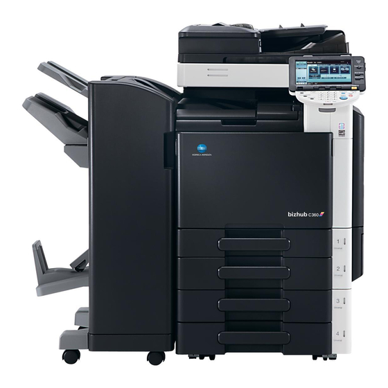
Page 56: Outline
[19] [22] [13] [18] [17] [16] [15] [14] A0EDF1E503DA [1] bizhub C360/C280/C220 [13] Mount kit MK-713 * Except for Europe area [2] Reverse automatic document feeder DF-617 [14] Desk DK-507 * Except for Europe area [3] Assist handle AH-101 [15] Paper feed cabinet... -
Page 57: I-Option Lk-101 V2/102/103 V2/105
2/2 System rear view A0EDF1E504DA bizhub C360/C280/C220 Mount kit MK-720 Fax kit FK-502 Key counter kit KIT-1 Image controller IC-412 i-Option LK-101 v2/102/103 v2/105 * bizhub C360/C280 only Security kit SC-507 Upgrade kit UK-203 Video interface kit VI-505 * bizhub C360/C280 only... -
Page 58: Product Specifications
Field Service Ver. 2.1 Feb. 2012 2. PRODUCT SPECIFICATIONS PRODUCT SPECIFICATIONS Type Type Desktop/console *1 scanner/printer Printing process Laser electrostatic printing system PC drum type OPC drum: KM-12 (OPC with high mold releasability) Scanning density 600 dpi Exposure lamp White rare-gas fluorescent lamp 30 W Platen Stationary (mirror scan) Original scanning... -
Page 59: Functions
Processing speed Plain paper bizhub C362/C280: 166.6 mm/s (black, full color), bizhub C220: 111.0 mm/s OHP film *2 Thick 1, Thick 2, bizhub C360/C280/C220: 55.5 mm/s Thick 3, Thick 4, Post card, Envelope, Label sheet Plain paper (glossy mode) Copying/printing... - Page 60 Field Service Ver. 2.1 Feb. 2012 2. PRODUCT SPECIFICATIONS Fixed zoom ratios Full size x1.000 Reduction Metric area x0.500, x0.707, x0.816, x0.866 Inch area x0.500, x0.647, x0.733, x0.785 Enlargement Metric area x1.154, x1.224, x1.414, x2.000 Inch area x1.214, x1.294, x1.545, x2.000 Zoom ratios memory 3 memories ×0.250 to ×4.000...
-
Page 61: Paper
2. PRODUCT SPECIFICATIONS Field Service Ver. 2.1 Feb. 2012 Paper Paper source (maximum tray capacity) Type Tray 1 Tray 2 Manual bypass tray ❍ (500 sheets) ❍ (500 sheets) ❍ (150 sheets) Plain paper (60 to 90 g/m / 16 to 24 lb) ⎯... -
Page 62: Materials
Field Service Ver. 2.1 Feb. 2012 2. PRODUCT SPECIFICATIONS Materials Parts name Number of prints Type name Toner cartridge/C bizhub C360 26,000 prints *1 TN319C bizhub C280/C220 26,000 prints *1 TN216C Toner cartridge/M bizhub C360 26,000 prints *1 TN319M bizhub C280/C220... -
Page 63: Print Volume
2. PRODUCT SPECIFICATIONS Field Service Ver. 2.1 Feb. 2012 Print volume • bizhub C360 Average Color print 1,700 prints/month Black print 5,000 prints/month Maximum Color print 5,000 prints/month Black print 15,000 prints/month Average Color print 2,200 prints/month Black print 6,500 prints/month... -
Page 64: Machine Specifications
Field Service Ver. 2.1 Feb. 2012 2. PRODUCT SPECIFICATIONS Machine specifications Power requirements Voltage: AC 100 V, 120 V, 127 V, 220-240 V Current: 100 V 15 A 110 V 15 A 120 V 12 A 127 V 12 A 230 V 50/60 Hz ±... - Page 65 2. PRODUCT SPECIFICATIONS Field Service Ver. 2.1 Feb. 2012 Supported computer IBM PC/AT compatible machine, Macintosh (PowerPC/Intel processor: Only MacOS X 10.4/10.5 for Intel processor) Printer driver PCL KONICAMINOLTA Windows NT Workstation Version 4.0 (SP6 or later) driver (PCL driver) Windows NT Server Version 4.0 (SP6 or later) Windows 2000 Professional (SP4 or later) Windows 2000 Server (SP3 or later)
- Page 66 Field Service Ver. 2.1 Feb. 2012 2. PRODUCT SPECIFICATIONS Printer driver XPS KONICAMINOLTA Windows Vista Business * driver (XPS driver) Windows Vista Enterprise * Windows Vista Home Basic * Windows Vista Home Premium * Windows Vista Ultimate * Windows Server 2008 Standard * Windows Server 2008 Enterprise * Windows 7 Home Premium/Professional/Ultimate * * 32 bits (x86)/64 bits (x64) environment are...
-
Page 67: Scan Functions
2. PRODUCT SPECIFICATIONS Field Service Ver. 2.1 Feb. 2012 Scan functions Scanner Scannable range Same as the copier (Max. 11 x 17: inch area, A3: metric area) Scan speed 70 pages/min (A4 or 8 1/2 x 11, Resolution 300 dpi) Functions Scan to E-mail, Scan to FTP, Scan to SMB, Scan to WebDAV, Scan to BOX... - Page 68 Field Service Ver. 2.1 Feb. 2012 2. PRODUCT SPECIFICATIONS NOTE • These specifications are subject to change without notice.
- Page 69 2. PRODUCT SPECIFICATIONS Field Service Ver. 2.1 Feb. 2012 Blank Page...
-
Page 70: Maintenance
Field Service Ver. 2.1 Feb. 2012 3. PERIODICAL MAINTENANCE ITEMS MAINTENANCE PERIODICAL MAINTENANCE ITEMS Concept of periodical maintenance • Cleaning/replacement cycle for each maintenance item of main body/options can be evaluated with the total counter or each life counter value of [Service Mode] → [Counter] →... - Page 71 3. PERIODICAL MAINTENANCE ITEMS Field Service Ver. 2.1 Feb. 2012 D. Periodical maintenance 4 (life counter; every 300,000 counts) Lubri- Descrip- Section Description/part name Clean Check Replace cation tions ● Paper feed Tray 1 pick-up roller section ● Tray 1 feed roller Tray 1 separation roller ●...
- Page 72 Field Service Ver. 2.1 Feb. 2012 3. PERIODICAL MAINTENANCE ITEMS B. Periodical maintenance 2 (life counter; every 200,000 counts) Lubri- Descrip- Section Description/part name Clean Check Replace cation tions ● Paper feed Pick-up roller section ● Feed roller ● Separation roller *1: Replace those three parts at the same time.
- Page 73 3. PERIODICAL MAINTENANCE ITEMS Field Service Ver. 2.1 Feb. 2012 B. Periodical maintenance 2 (life counter; every 800,000 counts) Lubri- Descrip- Section Description/part name Clean Check Replace cation tions ● FS-527 Upper paddle Conveyance Lower paddle ● section 3.1.6 FS-529 A.
-
Page 74: Periodical Replacement Parts List
• Maintenance conditions are based on the case of A4 or 8 x 11, standard mode and low power mode OFF. Color *Standard mode bizhub C360 4 pages per job 4 pages per job bizhub C280 3 pages per job... - Page 75 3. PERIODICAL MAINTENANCE ITEMS Field Service Ver. 2.1 Feb. 2012 Descrip Ref. Classification Parts name Parts No. Replacing cycle tions page Image Transfer belt unit A0ED R716 XX C360/C280: P.34 transfer 300,000 *3 section C220:260,000 *3 Transfer roller unit A0ED R717 XX C360/C280: P.36 300,000 *3...
-
Page 76: Periodical Cleaning Parts List
Field Service Ver. 2.1 Feb. 2012 3. PERIODICAL MAINTENANCE ITEMS Periodical cleaning parts list • Clean with reference to the numeric values displayed on the total counter, the life counter or the messages displayed on the control panel. 3.3.1 Main body Descrip Classification Parts name... -
Page 77: Concept Of Parts Life
3. PERIODICAL MAINTENANCE ITEMS Field Service Ver. 2.1 Feb. 2012 Concept of parts life 3.4.1 Life value of consumables and parts • The life counter value of each materials and parts is available from [Service Mode] → [Counter] → [Life]. •... - Page 78 Field Service Ver. 2.1 Feb. 2012 3. PERIODICAL MAINTENANCE ITEMS Rotation time Life threshold Life stop Description excess warning value threshold value threshold value Drum unit/ Rotation time of the PC C360/C280: C360/C280: C360/C280: Y,M,C drum and number of prints 5,676 M 6,244 M 6,811 M *3...
-
Page 79: Conditions For Life Specifications Values
Paper size Color ratio Black to Color = 3:1 PV/M bizhub C360 Average Bk: 5,000 / Color: 1,700 (US), Bk: 6,500 / Color: 2,200 (EU) Maximum Bk: 15,000 / Color: 5,000 (US), Bk: 18,000 / Color: 6,000 (EU) bizhub C280 Average... -
Page 80: Periodical Maintenance Procedure
Housing section 4.1.1 Replacing the ozone filter A. Periodically replacing parts/cycle • Ozone filter: Every 300,000 counts (bizhub C360/C280) Every 260,000 counts (bizhub C220) B. Procedure 1. Grip the handle on the ozone filter [1] and slide it out of the machine. -
Page 81: Photo Conductor Section
Photo conductor section 4.2.1 Replacing the drum unit A. Periodically replacing parts/cycle • Drum unit/Y,M,C : Every 90,000 counts (bizhub C360) Every 75,000 counts (bizhub C280) Every 55,000 counts (bizhub C220) • Drum unit/K : Every 120,000 counts (bizhub C360) - Page 82 Field Service Ver. 2.1 Feb. 2012 4. PERIODICAL MAINTENANCE PROCEDURE C. Reinstall procedure 1. Remove the drum unit [1] from its package. 2. Remove the drum unit [1] from the plastic bag. A0EDF2C517DA 3. Remove the tape and packing mate- rial [1].
-
Page 83: Maintenance
4. PERIODICAL MAINTENANCE PROCEDURE Field Service Ver. 2.1 Feb. 2012 5. Align the “ ” mark on the drum unit with the “ ” mark on the machine and insert the drum unit [1] into the machine. A0EDF2C520DA 6. Remove the photo conductor protec- tive sheet [1]. -
Page 84: Charging Section
Field Service Ver. 2.1 Feb. 2012 4. PERIODICAL MAINTENANCE PROCEDURE 8. Turn the drum unit lock lever [1] and lock the drum unit. NOTE • If the lock lever is hard to rotate, turn the lever while pushing the drum unit to the rear. A0EDF2C523DA 9. -
Page 85: Developing Section
4. PERIODICAL MAINTENANCE PROCEDURE Field Service Ver. 2.1 Feb. 2012 Developing section 4.4.1 Replacing the developing unit A. Periodically replacing parts/cycle • Developing unit/Y,M,C : Every 114,000 counts • Developing unit/K : Every 570,000 counts NOTE • Although the procedure shown below is for the replacement of the developing unit/Y, use the same procedure to replace other developing units. -
Page 86: Toner Supply Section
Field Service Ver. 2.1 Feb. 2012 4. PERIODICAL MAINTENANCE PROCEDURE 7. To reinstall, reverse the order of removal. NOTE • To install the two screws in the developing unit, press the position [1] with your finger as shown in the illustration. - Page 87 4. PERIODICAL MAINTENANCE PROCEDURE Field Service Ver. 2.1 Feb. 2012 C. Reinstall procedure 1. Remove the new toner cartridge [1] from its packaging, and the shake the cartridge side to side 5 to 10 times. NOTE • Shake the toner cartridge well. If shaking is not enough, that may cause trouble.
-
Page 88: 1St Transfer Section
Field Service Ver. 2.1 Feb. 2012 4. PERIODICAL MAINTENANCE PROCEDURE 1st transfer section 4.6.1 Cleaning of the image transfer entrance guide A. Periodically cleaning parts/cycle • Image transfer entrance guide: Every 240,000 counts or when the transfer belt unit is replaced B. -
Page 89: Replacing The Transfer Belt Unit
4.6.3 Replacing the transfer belt unit A. Periodically replacing parts/cycle • Transfer belt unit : Every 300,000 counts (bizhub C360) Every 260,000 counts (bizhub C280/C220) NOTE • Before replacement operations of the transfer belt unit, make sure to turn OFF the main power switch and the sub power switch. - Page 90 Field Service Ver. 2.1 Feb. 2012 4. PERIODICAL MAINTENANCE PROCEDURE 6. Hold the both sides and lift it to take out the transfer belt unit [1] a little. A0EDF2C010DA 7. Hold the position [1] as shown in the left and remove the transfer belt unit [2].
-
Page 91: 2Nd Transfer/Separation Section
2nd transfer/separation section 4.7.1 Replacing the transfer roller unit A. Periodically replacing parts/cycle • Transfer roller unit: Every 300,000 counts (bizhub C360) Every 260,000 counts (bizhub C280/C220) B. Removal procedure 1. Open the right door and the regist unit. 2. Unlock the lock levers [1] of the transfer roller unit (at two places). -
Page 92: Toner Collection Section
Field Service Ver. 2.1 Feb. 2012 4. PERIODICAL MAINTENANCE PROCEDURE C. Reinstall procedure 1. Holding onto the lock levers [1] (at two places), mount the new transfer roller unit [2]. 2. Lock the lock levers [1] (at two places). NOTE •... -
Page 93: Cleaning Of The Area Around The Waste Toner Collecting Port
4. PERIODICAL MAINTENANCE PROCEDURE Field Service Ver. 2.1 Feb. 2012 4. Take out the cap [1] from the new waste toner box package, and attach it to the old waste toner box. A0EDF2C507DA C. Reinstall procedure 1. Remove the brand new waste toner box from its package and remove the packing material. -
Page 94: Paper Feed Section
Field Service Ver. 2.1 Feb. 2012 4. PERIODICAL MAINTENANCE PROCEDURE Paper feed section 4.9.1 Replacing the tray 1 feed roller/tray 1 pick-up roller A. Periodically replacing parts/cycle • Tray 1 feed roller: Every 300,000 counts • Tray 1 pick-up roller: Every 300,000 counts B. - Page 95 4. PERIODICAL MAINTENANCE PROCEDURE Field Service Ver. 2.1 Feb. 2012 5. Remove the C-clip [1], and remove the tray 1 pick-up roller [2]. A0EDF2C018DA 6. Remove the C-clip [1] and the bear- ing [2]. A0EDF2C019DA 7. Remove the C-ring [1] and the bear- ing [2].
-
Page 96: Replacing The Tray 1 Separation Roller Assy
Field Service Ver. 2.1 Feb. 2012 4. PERIODICAL MAINTENANCE PROCEDURE 9. Remove the C-ring [1], and remove the tray 1 feed roller [2]. A0EDF2C022DA 10. To reinstall, reverse the order of removal. 11. Replace the tray 1 separation roller assy. See P.41 12. - Page 97 4. PERIODICAL MAINTENANCE PROCEDURE Field Service Ver. 2.1 Feb. 2012 3. Remove two screws [1], and remove the tray 1 separation roller unit [2]. A0EDF2C024DA 4. Remove the C-ring [1], and remove the shaft [2] and the cover [3]. NOTE •...
-
Page 98: Replacing The Tray 2 Feed Roller/Tray 2 Pick-Up Roller
Field Service Ver. 2.1 Feb. 2012 4. PERIODICAL MAINTENANCE PROCEDURE 4.9.3 Replacing the tray 2 feed roller/tray 2 pick-up roller A. Periodically replacing parts/cycle • Tray 2 feed roller: Every 300,000 counts • Tray 2 pick-up roller: Every 300,000 counts B. - Page 99 4. PERIODICAL MAINTENANCE PROCEDURE Field Service Ver. 2.1 Feb. 2012 3. Remove two screws [1], and remove the feed roller cover [2]. A0EDF2C028DA 4. Remove the C-ring [1] and the bear- ing [2]. A0EDF2C029DA 5. Move the shaft [1] in the direction as shown in the illustration.
-
Page 100: Replacing The Manual Bypass Tray Separation Roller Assy
Field Service Ver. 2.1 Feb. 2012 4. PERIODICAL MAINTENANCE PROCEDURE 7. To reinstall, reverse the order of removal. 8. Replace the manual bypass tray separation roller assy. See P.45 9. Select [Service Mode] → [Counter] → [Life] and clear the count of [Manual Tray]. See P.453 4.9.6 Replacing the manual bypass tray separation roller assy... - Page 101 4. PERIODICAL MAINTENANCE PROCEDURE Field Service Ver. 2.1 Feb. 2012 5. Remove two screws [1], and remove the manual bypass tray separation roller cover [2]. A0EDF2C032DA 6. Remove two screws [1], and remove the manual bypass tray separation roller unit [2]. A0EDF2C033DA 7.
-
Page 102: 4.10 Registration Section
Field Service Ver. 2.1 Feb. 2012 4. PERIODICAL MAINTENANCE PROCEDURE 4.10 Registration section 4.10.1 Cleaning of the timing roller A. Periodically cleaning parts/cycle • Timing roller: Every 60,000 counts (upon each call) B. Procedure 1. Open the right door and the regist unit. 2. - Page 103 4. PERIODICAL MAINTENANCE PROCEDURE Field Service Ver. 2.1 Feb. 2012 3. Remove three screws [1], and remove right door hinge cover [2]. A0EDF2C008DA 4. Open the right door and the regist unit. 5. Remove the screw [1] each, and remove the two connector protective covers [2].
-
Page 104: 4.12 Duplex Section
Field Service Ver. 2.1 Feb. 2012 4. PERIODICAL MAINTENANCE PROCEDURE 8. Remove two screws [1], and remove the fusing unit [2]. NOTE • When removing the fusing unit, hold the parts shown on the picture on the left so that it would not fall. A0EDF2C038DA 4.12 Duplex section 4.12.1... -
Page 105: Other Maintenance Items
5. OTHER MAINTENANCE ITEMS Field Service Ver. 2.1 Feb. 2012 OTHER MAINTENANCE ITEMS Disassembly/adjustment prohibited items A. Paint-locked screws NOTE • To prevent loose screws, a screw lock in blue or green series color is applied to the screws. • The screw lock is applied to the screws that may get loose due to the vibrations and loads created by the use of machine or due to the vibrations created during transportation. -
Page 106: Notes When Transporting The Machine
Field Service Ver. 2.1 Feb. 2012 5. OTHER MAINTENANCE ITEMS Notes when transporting the machine • When transporting a machine to reinstall it in another location, attach the following pro- tective materials to the machine in order to prevent the machine from being damaged or spilling out by vibration during transportation. -
Page 107: Disassembly/Reassembly Parts List
5. OTHER MAINTENANCE ITEMS Field Service Ver. 2.1 Feb. 2012 Disassembly/reassembly parts list Section Part name Ref. page Exterior parts Front door P.55 Left cover P.55 Exit tray P.56 Rear right cover P.56 Upper right cover P.56 Upper rear cover P.57 Lower rear cover/1 P.57... - Page 108 Field Service Ver. 2.1 Feb. 2012 5. OTHER MAINTENANCE ITEMS Section Part name Ref. page Boards Scanner relay board (REYB/SCAN) P.93 Inverter board (INVB) P.93 Machine condition monitor board (MCMB) P.95 Front side relay board (FREYB) P.95 DC power supply (DCPU) P.96 PH relay board (PHREYB) P.97...
-
Page 109: Cleaning Parts List
5. OTHER MAINTENANCE ITEMS Field Service Ver. 2.1 Feb. 2012 Cleaning parts list Section Part name Ref. page Processing section Transfer belt unit P.139 PH window P.139 Tray 1 Tray 1 feed roller P.140 Tray 1 pick-up roller Tray 1 separation roller Tray 2 Tray 2 feed roller P.141... -
Page 110: Disassembly/Reassembly Procedure
Field Service Ver. 2.1 Feb. 2012 5. OTHER MAINTENANCE ITEMS Disassembly/reassembly procedure 5.5.1 Front door 1. Open the front door. 2. Remove two screws [1], and remove two stoppers [2]. A0EDF2C041DA 3. Remove the C-clip [1], and remove the front door [2]. A0EDF2C042DA 5.5.2 Left cover... -
Page 111: Exit Tray
5. OTHER MAINTENANCE ITEMS Field Service Ver. 2.1 Feb. 2012 5.5.3 Exit tray 1. Open the front door. 2. Remove the left cover. See P.55 3. Remove three screws [1], and remove the exit tray [2]. A0EDF2C044DA 5.5.4 Rear right cover 1. -
Page 112: Upper Rear Cover
Field Service Ver. 2.1 Feb. 2012 5. OTHER MAINTENANCE ITEMS 5.5.6 Upper rear cover 1. Remove the scanner rear cover. See P.58 2. Remove six screws [1], and remove the upper rear cover [2]. A0EDF2C047DA 5.5.7 Lower rear cover/1 1. Remove four screws [1], and remove the lower rear cover/1 [2]. -
Page 113: Scanner Rear Cover
5. OTHER MAINTENANCE ITEMS Field Service Ver. 2.1 Feb. 2012 2. Remove six screws [1], and remove the lower rear cover/2 [2]. A0EDF2C050DA 5.5.9 Scanner rear cover 1. Remove three screws [1], and remove the scanner rear cover [2]. A0EDF2C051DA 5.5.10 Scanner right cover 1. -
Page 114: Scanner Right Front Cover
Field Service Ver. 2.1 Feb. 2012 5. OTHER MAINTENANCE ITEMS 5.5.11 Scanner right front cover 1. Remove the screw [1], and remove the scanner right front cover [2]. A0EDF2C053DA 5.5.12 USB interface cover 1. Remove the scanner right front cover. See P.59 2. -
Page 115: Scanner Upper Front Cover
5. OTHER MAINTENANCE ITEMS Field Service Ver. 2.1 Feb. 2012 5.5.14 Scanner upper front cover 1. Remove three screws [1], and remove the scanner upper front cover [2]. A0EDF2C056DA 5.5.15 Scanner left cover 1. Remove three screws [1], and remove the scanner left cover [2]. A0EDF2C057DA 5.5.16 Scanner upper rear cover... -
Page 116: Scanner Front Cover
Field Service Ver. 2.1 Feb. 2012 5. OTHER MAINTENANCE ITEMS 5.5.17 Scanner front cover 1. Remove the scanner left cover. See P.60 2. Remove the scanner right front cover. See P.59 3. Remove the scanner left front cover. See P.59 4. -
Page 117: Slit Glass Cover
5. OTHER MAINTENANCE ITEMS Field Service Ver. 2.1 Feb. 2012 5.5.18 Slit glass cover 1. Remove the scanner upper rear cover. See P.60 2. Remove two screws [1], and remove the slit glass cover [2]. A0EDF2C062DA 5.5.19 Original glass 1. Remove the scanner right cover. See P.58 2. -
Page 118: Control Panel Assy
Field Service Ver. 2.1 Feb. 2012 5. OTHER MAINTENANCE ITEMS 5.5.20 Control panel assy 1. Remove two screws [1], and discon- nect the connector [2]. A0EDF2C065DA 2. Remove the screw [1], and remove the control panel assy [2]. A0EDF2C066DA 5.5.21 Tray 1 1. -
Page 119: Tray 2
5. OTHER MAINTENANCE ITEMS Field Service Ver. 2.1 Feb. 2012 3. Remove the tray 1 [1]. A0EDF2C068DA 5.5.22 Tray 2 1. Slide out the tray 2. 2. Remove the screw [1], and remove the stopper [2]. A0EDF2C069DA 3. Remove the tray 2 [1]. A0EDF2C070DA... -
Page 120: Front Side Relay Board Cover
Field Service Ver. 2.1 Feb. 2012 5. OTHER MAINTENANCE ITEMS 5.5.23 Front side relay board cover 1. Remove the waste toner box. See P.37 2. Remove three screws [1], and remove the front side relay board cover [2]. A0EDF2C071DA 5.5.24 Front cover 1. -
Page 121: Tray 1 Paper Feed Unit
5. OTHER MAINTENANCE ITEMS Field Service Ver. 2.1 Feb. 2012 5.5.25 Tray 1 paper feed unit 1. Slide out the tray 1. 2. Remove the rear right cover. See P.56 3. Disconnect two connectors [1]. A0EDF2C007DA 4. Remove three screws [1], and remove right door hinge cover [2]. -
Page 122: Tray 2 Paper Feed Unit
Field Service Ver. 2.1 Feb. 2012 5. OTHER MAINTENANCE ITEMS 7. Remove the harnesses from the edge cover [1], and disconnect two connectors [2]. A0EDF2C074DA 8. Remove four screws [1], and remove the tray 1 paper feed unit [2]. A0EDF2C075DA 5.5.26 Tray 2 paper feed unit 1. - Page 123 5. OTHER MAINTENANCE ITEMS Field Service Ver. 2.1 Feb. 2012 4. Remove three screws [1], and remove right door hinge cover [2]. A0EDF2C008DA 5. Open the right door and the regist unit. 6. Unhook two tabs [1], and remove the connector cover [2].
-
Page 124: Ph Unit
Field Service Ver. 2.1 Feb. 2012 5. OTHER MAINTENANCE ITEMS 8. Remove four screws [1], and remove the tray 2 paper feed unit [2]. A0EDF2C077DA 5.5.27 PH unit CAUTION • Do not replace the printer head unit while the power is ON. Laser beam generated during the above mentioned activity may cause blindness. - Page 125 5. OTHER MAINTENANCE ITEMS Field Service Ver. 2.1 Feb. 2012 4. Remove the cable holder [1] of the flat cable. 5. Move the flat cable to the position [2] shown in the illustration and secure it with the cable holder. A0EDF2C079DA 6.
- Page 126 Field Service Ver. 2.1 Feb. 2012 5. OTHER MAINTENANCE ITEMS 9. Remove the PH unit [1]. A0EDF2C082DA 10. To reinstall, reverse the order of removal. 11. Select [Skew adjustment] after selecting [Service Mode] → [Machine] → [Skew adjustment], and input the adjustment value that is put on the side of the replaced PH unit.
-
Page 127: Ccd Board Unit
5. OTHER MAINTENANCE ITEMS Field Service Ver. 2.1 Feb. 2012 5.5.28 CCD board unit A. Removal procedure 1. Remove the original glass. See P.62 2. Remove nine screws [1], and remove the CCD board protective shield [2]. A0EDF2C244DA 3. Disconnect two connectors [1]. A0EDF2C083DA 4. -
Page 128: Exposure Unit
Field Service Ver. 2.1 Feb. 2012 5. OTHER MAINTENANCE ITEMS B. Reinstall procedure 1. Set the CCD unit to the mounting position at the center of the scale, and fix it with four screws. A0EDF2C085DA 2. Reinstall the original glass. 3. - Page 129 5. OTHER MAINTENANCE ITEMS Field Service Ver. 2.1 Feb. 2012 5. Move the exposure unit [1] to the position where the sheets are removed (where a screwdriver can reach the screws) in the previous step. 6. Remove two screws [2], and remove the exposure unit [1].
-
Page 130: Sub Hopper Assy
Field Service Ver. 2.1 Feb. 2012 5. OTHER MAINTENANCE ITEMS 5.5.30 Sub hopper assy 1. Open the right door. 2. Remove the front cover. See P.55 3. Remove the toner cartridge/Y,M,C,K. See P.31 4. Remove the drum unit/Y,M,C,K. See P.26 5. -
Page 131: Right Door Assy
5. OTHER MAINTENANCE ITEMS Field Service Ver. 2.1 Feb. 2012 5.5.31 Right door assy 1. Remove the rear right cover. See P.56 2. Disconnect two connectors [1]. A0EDF2C007DA 3. Remove three screws [1], and remove right door hinge cover [2]. A0EDF2C008DA 4. - Page 132 Field Service Ver. 2.1 Feb. 2012 5. OTHER MAINTENANCE ITEMS 5. To mark the position where the right door assy is installed, draw two guide lines on the scales [1] indi- cated on the machine frame. A0EDF2C094DA 6. Open the right door. 7.
-
Page 133: Manual Bypass Tray Unit
5. OTHER MAINTENANCE ITEMS Field Service Ver. 2.1 Feb. 2012 10. Remove three screws [1], and remove the hinge (upper) [2]. A0EDF2C096DA 11. Raise the right door and remove the right door assy [1]. A0EDF2C097DA NOTE • When installing the right door assy, align it with the guide lines drawn on the scales indicated on the machine frame. - Page 134 Field Service Ver. 2.1 Feb. 2012 5. OTHER MAINTENANCE ITEMS 3. Remove two screws [1] and shift the support [2]. A0EDF2C099DA 4. Remove the screw [1], and remove the cover [2]. A0EDF2C100DA 5. Remove the screw [1], and remove the cover [2]. A0EDF2C101DA 6.
- Page 135 5. OTHER MAINTENANCE ITEMS Field Service Ver. 2.1 Feb. 2012 7. Remove the harness from five wire saddles [1] and the edge cover [2], and disconnect the connector [3]. A0EDF2C103DA 8. Remove 13 screws [1]. A0EDF2C104DA 9. Remove the manual bypass tray unit [1].
-
Page 136: Regist Unit
Field Service Ver. 2.1 Feb. 2012 5. OTHER MAINTENANCE ITEMS 5.5.33 Regist unit 1. Remove the right door assy. See P.76 2. Remove the screw [1], and remove the connector cover [2]. A0EDF2C106DA 3. Remove the harness from the wire saddle [1], and disconnect the con- nector [2]. -
Page 137: Conveyance Unit
5. OTHER MAINTENANCE ITEMS Field Service Ver. 2.1 Feb. 2012 5. Remove two screws [1], and remove the hinge [2]. A0EDF2C109DA 6. Remove the regist unit [1]. A0EDF2C110DA 5.5.34 Conveyance unit 1. Remove the front cover. See P.65 2. Remove the harness from three wire saddles [1] and the edge cover [2]. -
Page 138: Hard Disk Drive (Hdd)
Field Service Ver. 2.1 Feb. 2012 5. OTHER MAINTENANCE ITEMS 5. Remove four screws [1], and remove the conveyance unit [2]. NOTE • When removing the conveyance unit, be careful not to damage or deform the guide sheet of the tray 1 paper feed unit. -
Page 139: How To Open Pwb Box
5. OTHER MAINTENANCE ITEMS Field Service Ver. 2.1 Feb. 2012 5. Remove four screws [1], and remove the metal plate [2]. 6. To reinstall, reverse the order of removal.. A0EDF2C113DA NOTE • When the hard disk is replaced, select [State Confirmation] → [Memory/HDD Adj.] →... - Page 140 Field Service Ver. 2.1 Feb. 2012 5. OTHER MAINTENANCE ITEMS 5. Remove the cable holder [1] A0EDF2C115DA 6. Remove the screw [1], and remove the metal plate [2]. A0EDF2C530DA 7. Remove 10 screws [1]. A0EDF2C116DA...
-
Page 141: Main Drive Unit
5. OTHER MAINTENANCE ITEMS Field Service Ver. 2.1 Feb. 2012 8. Open the PWB box as shown in the illustration. Slide the PWB box 20 mm to the direction shown in the illustration. Open the PWB box 15 degrees. Slide the PWB box 20 mm to the direction shown in the illustration and open it 75 degrees. - Page 142 Field Service Ver. 2.1 Feb. 2012 5. OTHER MAINTENANCE ITEMS 6. Remove the harnesses from the wire saddle [1] and the edge cover [2], and disconnect the connector [3]. A0EDF2C118DA 7. Remove the high voltage unit. See P.104 8. Remove the harness from two wire saddles [1].
- Page 143 5. OTHER MAINTENANCE ITEMS Field Service Ver. 2.1 Feb. 2012 10. Disconnect two connectors [1], and remove the harnesses from the wire saddle [2]. [1] [2] A0EDF2C121DA 11. Remove the harnesses from the har- ness guide [1]. 12. Remove two screws [2], and remove the harness guide [1].
- Page 144 Field Service Ver. 2.1 Feb. 2012 5. OTHER MAINTENANCE ITEMS 15. Disconnect four connectors [1]. A0EDF2C125DA 16. Open the right door. 17. Loosen the screw (ground line) [1]. A0EDF2C126DA 18. Remove 11 screws [1], and pull the main drive unit [2] out. 19.
-
Page 145: Fusing Drive Unit
5. OTHER MAINTENANCE ITEMS Field Service Ver. 2.1 Feb. 2012 5.5.38 Fusing drive unit 1. Remove the upper rear cover. See P.57 2. Remove the fusing unit. See P.47 3. Remove three screws [1]. A0EDF2C197DA 4. Remove the harnesses from the wire saddle [1]. - Page 146 Field Service Ver. 2.1 Feb. 2012 5. OTHER MAINTENANCE ITEMS 7. Remove the harness from the edge cover [1], and disconnect two con- nectors [3]. 8. Remove four screws [2], and remove the duct assy [4]. A0EDF2C200DA 9. Disconnect four connectors [1]. 10.
-
Page 147: Hopper Drive Unit (C/K, Y/M)
5. OTHER MAINTENANCE ITEMS Field Service Ver. 2.1 Feb. 2012 12. Remove eight screws [1], pull the fusing drive unit [2] to you, and remove it. A0EDF2C130DA 5.5.39 Hopper drive unit (C/K, Y/M) A. Hopper drive unit (Y/M) 1. Remove the toner cartridge motor/YM. See P.118 2. -
Page 148: Scanner Relay Board (Reyb/Scan)
Field Service Ver. 2.1 Feb. 2012 5. OTHER MAINTENANCE ITEMS 5.5.40 Scanner relay board (REYB/SCAN) 1. Remove the scanner upper rear cover. See P.60 2. Disconnect all connectors on the scanner relay board. A0EDF2C133DA 3. Remove five screws [1], and remove the scanner relay board [2]. - Page 149 5. OTHER MAINTENANCE ITEMS Field Service Ver. 2.1 Feb. 2012 3. Remove the harnesses from two edge covers [1]. A0EDF2C136DA 4. Remove two screws [1], and remove the inverter board assy [2]. A0EDF2C137DA 5. Remove two screws [1] and two PWB supports [2], and remove the inverter board [3].
-
Page 150: Machine Condition Monitor Board (Mcmb)
Field Service Ver. 2.1 Feb. 2012 5. OTHER MAINTENANCE ITEMS 5.5.42 Machine condition monitor board (MCMB) 1. Remove the scanner front cover. See P.61 2. Disconnect the connector [2]. 3. Remove two screws [1], and remove the machine condition monitor board [3]. -
Page 151: Dc Power Supply (Dcpu)
5. OTHER MAINTENANCE ITEMS Field Service Ver. 2.1 Feb. 2012 5.5.44 DC power supply (DCPU) CAUTION • Remove the DC power supply after six minutes or more have passed since the power plug was disconnected. 1. Remove the left cover. See P.55 2. -
Page 152: Ph Relay Board (Phreyb)
Field Service Ver. 2.1 Feb. 2012 5. OTHER MAINTENANCE ITEMS 6. Remove four screws [1], and remove the DC power supply [2]. A0EDF2C144DA 5.5.45 PH relay board (PHREYB) 1. Remove the DC power supply. See P.96 2. Disconnect all connectors and flat cables on the PH relay board. -
Page 153: Printer Control Board (Prcb)
5. OTHER MAINTENANCE ITEMS Field Service Ver. 2.1 Feb. 2012 5.5.46 Printer control board (PRCB) 1. Remove the lower rear cover/1. See P.57 2. Remove the lower rear cover/2. See P.57 3. Remove the screw [1], and remove the metal plate [2]. A0EDF2C147DA 4. -
Page 154: Service Eeprom Board (Sverb)
Field Service Ver. 2.1 Feb. 2012 5. OTHER MAINTENANCE ITEMS 6. Disconnect all connectors on the printer control board. A0EDF2C150DA 7. Remove six screws [1], and remove printer control board [2]. A0EDF2C151DA NOTE • When the printer control board is to be replaced, rewriting the firmware to the lat- est one. - Page 155 5. OTHER MAINTENANCE ITEMS Field Service Ver. 2.1 Feb. 2012 NOTE After replacing the service EEPROM board, all parts shown below are required to be replaced with new ones. • Developing unit/Y,M,C,K • Drum unit/Y,M,C,K • Toner cartridge/Y,M,C,K • Image transfer belt unit •...
-
Page 156: Mfp Board (Mfpb)
Field Service Ver. 2.1 Feb. 2012 5. OTHER MAINTENANCE ITEMS Order Items that require readjustment in the Service Mode Ref. page Machine Printer Area Paper Feed Direction Adj. P.377 Fusing Transport Speed P.372 Printer Area Printer Image Centering P.374 Side 1 Prt. - Page 157 5. OTHER MAINTENANCE ITEMS Field Service Ver. 2.1 Feb. 2012 6. Disconnect two connectors [1]. 7. Remove two screws [2], and remove the hard disk assy [3]. A0EDF2C154DA 8. Remove three screws [1], and remove the PWB rail (upper side) [2]. A0EDF2C155DA 9.
- Page 158 Field Service Ver. 2.1 Feb. 2012 5. OTHER MAINTENANCE ITEMS 10. Remove 10 screws [1] of the MFP board. A0EDF2C157DA 11. Open the PWB box. See P.84 12. Remove five screws [1], and remove the MFP board assy [2]. A0EDF2C158DA 13.
-
Page 159: High Voltage Unit (Hv)
5. OTHER MAINTENANCE ITEMS Field Service Ver. 2.1 Feb. 2012 14. Remove two ground plates [1]. A0EDF2C161DA 15. Remove six bolts [1], and remove the interface cover [2]. A0EDF2C160DA 16. Remove the DIMM. 17. Remove the NVRAM. NOTE • When the MFP board is to be replaced, rewriting the firmware to the latest one. 5.5.49 High voltage unit (HV) 1. -
Page 160: Sodimm (Dimm)
Field Service Ver. 2.1 Feb. 2012 5. OTHER MAINTENANCE ITEMS 3. Remove seven screws [1], unhook the tab [2], and remove the high volt- age unit [3]. NOTE • Install the high voltage unit so that the machine terminals come into contact with the counterparts on the high voltage unit and the high voltage unit properly fit into the tab. -
Page 161: Nvram Board (Nrb)
5. OTHER MAINTENANCE ITEMS Field Service Ver. 2.1 Feb. 2012 5.5.51 NVRAM board (NRB) 1. Remove the lower rear cover/1. See P.57 2. Remove 12 screws [1], and remove the MFP board protective shield [2]. A0EDF2C153DA 3. Remove the NVRAM board [1] on the MFP board. -
Page 162: Paper Feed Tray 2 Paper Fd Sensor Board (Psdb/2)
Field Service Ver. 2.1 Feb. 2012 5. OTHER MAINTENANCE ITEMS 4. Disconnect the connector [1]. 5. Unhook two tabs [2], and remove the paper feed tray 1 paper FD sensor board assy [3]. A0EDF2C167DA 6. Remove the lever [1], and remove the paper feed tray 1 paper FD sen- sor board [2]. -
Page 163: Paper Feed Tray 1 Led Board, Paper Feed Tray 2 Led Board (Ledb1, Ledb2)
5. OTHER MAINTENANCE ITEMS Field Service Ver. 2.1 Feb. 2012 5. Remove the lever [1], and remove the paper feed tray 2 paper FD sen- sor board [2]. NOTE • When removing the lever, be careful not to deform the lever. A0EDF2C168DA 5.5.54 Paper feed tray 1 LED board, Paper feed tray 2 LED board (LEDB1, LEDB2) -
Page 164: Scanner Motor (M201)
Field Service Ver. 2.1 Feb. 2012 5. OTHER MAINTENANCE ITEMS 4. Remove the screw [1] each, discon- nect the connector [2] each, and remove the paper feed tray 1 LED board [3] and the paper feed tray 2 LED board [4]. A0EDF2C172DA 5.5.55 Scanner motor (M201) - Page 165 5. OTHER MAINTENANCE ITEMS Field Service Ver. 2.1 Feb. 2012 5. Remove the screw [1], and remove the angle sensor assy [2]. A0EDF2C174DA 6. Remove six screws [1], and remove the ADF base plate [2]. A0EDF2C175DA 7. Disconnect the connector [1], and remove three screws [2].
- Page 166 Field Service Ver. 2.1 Feb. 2012 5. OTHER MAINTENANCE ITEMS 8. Remove the spring [1] and the belt [2], and remove the scanner motor assy [3]. A0EDF2C177DA 9. Remove two screws [1], and remove the bracket [2]. A0EDF2C178DA 10. Remove two screws [1], and remove the damper [2].
-
Page 167: Duplex Transport Motor (M5)
5. OTHER MAINTENANCE ITEMS Field Service Ver. 2.1 Feb. 2012 B. Reinstall procedure 1. Temporarily secure the scanner motor assy [1] with three screws [2]. A0EDF2C179DA 2. With the scanner drive gear set screw [1] located on the right-hand side as shown on the left, slide the scanner motor assy [2] to the left and check that it is returned to the origi- nal position by the tension of the... - Page 168 Field Service Ver. 2.1 Feb. 2012 5. OTHER MAINTENANCE ITEMS 3. Disconnect the connector [1]. A0EDF2C181DA 4. Disconnect the connector [1], and remove the harnesses from six wire saddles [2]. A0EDF2C182DA 5. Remove 15 screws [1], and remove the metal plate [2]. A0EDF2C183DA 6.
-
Page 169: Toner Supply Motor/Ym, Ck (M8, M9)
5. OTHER MAINTENANCE ITEMS Field Service Ver. 2.1 Feb. 2012 7. Disconnect the connector [1], and remove the duplex transport motor [2]. A0EDF2C185DA 5.5.57 Toner supply motor/YM, CK (M8, M9) 1. Remove the sub hopper assy. See P.75 2. Disconnect six coonectors [1], and remove the harnesses from eight wire saddles [2]. -
Page 170: Transport Motor (M1)
Field Service Ver. 2.1 Feb. 2012 5. OTHER MAINTENANCE ITEMS 4. Remove two screws [1] each, and remove the toner supply motor/YM [2], CK [3]. A0EDF2C188DA 5.5.58 Transport motor (M1) 1. Open the PWB box. See P.84 2. Remove four screws [1], disconnect the connector [2], and remove the transport motor [3]. -
Page 171: Color Pc Motor (M2)
5. OTHER MAINTENANCE ITEMS Field Service Ver. 2.1 Feb. 2012 5.5.59 Color PC motor (M2) 1. Remove the upper rear cover. See P.57 2. Open the PWB box. See P.84 3. Remove four screws [1], disconnect the connector [2], and remove the color PC motor [3]. -
Page 172: Switchback Motor (M4)
Field Service Ver. 2.1 Feb. 2012 5. OTHER MAINTENANCE ITEMS 5.5.61 Switchback motor (M4) 1. Remove the upper rear cover. See P.57 2. Disconnect the connector [1]. 3. Remove two screws [2], and remove the switchback motor [3]. A0EDF2C192DA 5.5.62 Fusing pressure roller retraction motor (M11) 1. -
Page 173: Toner Cartridge Motor/Ym (M6)
5. OTHER MAINTENANCE ITEMS Field Service Ver. 2.1 Feb. 2012 5.5.63 Toner cartridge motor/YM (M6) 1. Remove the upper rear cover. See P.57 2. Remove the harness from the wire saddle [1], and disconnect the con- nector [2]. A0EDF2C195DA 3. Remove two screws [1], and remove the toner cartridge motor/YM [2]. - Page 174 Field Service Ver. 2.1 Feb. 2012 5. OTHER MAINTENANCE ITEMS 3. Remove the harness from the wire saddle [1]. 4. Disconnect the connector [2], and remove the cooling fan motor/3 assy [3]. A0EDF2C198DA 5. Remove three screws [1], and remove the duct [2]. A0EDF2C199DA 6.
-
Page 175: Color Dev. Unit Engaged Motor (M10)
5. OTHER MAINTENANCE ITEMS Field Service Ver. 2.1 Feb. 2012 8. Remove two screws [1], and remove the toner cartridge motor/CK [2]. A0EDF2C201DA 5.5.65 Color dev. unit engaged motor (M10) 1. Remove the main drive unit. See P.86 2. Remove three screws [1], and remove the color dev. -
Page 176: Paper Feed Tray 1 Lift-Up Motor (M12)
Field Service Ver. 2.1 Feb. 2012 5. OTHER MAINTENANCE ITEMS 5.5.66 Paper feed tray 1 lift-up motor (M12) 1. Remove the high voltage unit. See P.104 2. Remove the tray 1. See P.63 3. Remove the tray 2. See P.64 4. - Page 177 5. OTHER MAINTENANCE ITEMS Field Service Ver. 2.1 Feb. 2012 7. Remove the harnesses from two wire saddles [1]. A0EDF2C205DA 8. Remove four screws [1], and remove the paper feed lift-up unit [2]. A0EDF2C206DA 9. Remove three screws [1], disconnect the connector [2], and remove the paper feed tray 1 lift-up motor [3].
-
Page 178: Paper Feed Tray 2 Lift-Up Motor (M13)
Field Service Ver. 2.1 Feb. 2012 5. OTHER MAINTENANCE ITEMS 5.5.67 Paper feed tray 2 lift-up motor (M13) 1. Remove the paper feed lift-up unit. See P.121 2. Remove three screws [1], disconnect the connector [2], and remove the paper feed tray 2 lift-up motor [3]. A0EDF2C208DA 5.5.68 Transfer belt cleaner cooling fan motor (FM6) - Page 179 5. OTHER MAINTENANCE ITEMS Field Service Ver. 2.1 Feb. 2012 7. Remove the screw [1], and remove the rail [2] for the developing unit/Y. A0EDF2C210DA 8. Remove the screw [1] of the transfer belt cleaner cooling fan motor assy. A0EDF2C211DA 9.
-
Page 180: Paper Feed Tray 1 Paper Feed Clutch (Cl3)
Field Service Ver. 2.1 Feb. 2012 5. OTHER MAINTENANCE ITEMS 11. Remove two screws [1], disconnect the connector [2], and remove the transfer belt cleaner cooling fan motor [3]. A0EDF2C213DA 5.5.69 Paper feed tray 1 paper feed clutch (CL3) 1. Remove the tray 1 paper feed unit. See P.66 2. -
Page 181: Paper Feed Tray 2 Vertical Transport Clutch (Cl2)
5. OTHER MAINTENANCE ITEMS Field Service Ver. 2.1 Feb. 2012 5.5.70 Paper feed tray 2 vertical transport clutch (CL2) 1. Remove the tray 2 paper feed unit. See P.67 2. Remove two screws [1] and the E- ring [2], and remove the metal plate [3]. -
Page 182: Manual Paper Feed Clutch (Cl7)
Field Service Ver. 2.1 Feb. 2012 5. OTHER MAINTENANCE ITEMS 3. Remove the gear [1]. 4. Disconnect the connector [2], and remove the harness from two wire saddles [3]. 5. Remove the E-ring [4], and remove the paper feed tray 2 paper feed clutch [5]. -
Page 183: Developing Clutch/K (Cl6)
5. OTHER MAINTENANCE ITEMS Field Service Ver. 2.1 Feb. 2012 5. Remove the screw [1], and remove the connector cover [2]. A0EDF2C027DA 6. Disconnect the connector [3], and remove the harness from the wire saddle [1] and the edge cover [2]. 7. -
Page 184: Registration Roller Clutch (Cl4)
Field Service Ver. 2.1 Feb. 2012 5. OTHER MAINTENANCE ITEMS 3. Remove four screws [1] and the E- ring [2], and remove the developing clutch/K cover [3]. A0EDF2C221DA 4. Remove the harness from the edge cover [1]. 5. Disconnect the connector [3], remove the E-ring [2], and remove the developing clutch/K [4]. -
Page 185: Idc Registration Sensor Shutter Solenoid (Sd2)
5. OTHER MAINTENANCE ITEMS Field Service Ver. 2.1 Feb. 2012 5.5.75 IDC registration sensor shutter solenoid (SD2) 1. Remove the conveyance unit. See P.82 2. Disconnect the connector [1], and remove the harnesses from the wire saddle [2] and the edge cover [3]. A0EDF2C224DA 3. -
Page 186: Idc Registration Sensor/Mk, Yc (Idcs/Mk, Yc) Assy
Field Service Ver. 2.1 Feb. 2012 5. OTHER MAINTENANCE ITEMS 6. Remove the screw [1], the pin [2] and the spacer [3], and remove the IDC registration sensor shutter sole- noid [4]. A0EDF2C535DA 5.5.76 IDC registration sensor/MK, YC (IDCS/MK, YC) assy 1. -
Page 187: Ph Window Cleaning Pad
5. OTHER MAINTENANCE ITEMS Field Service Ver. 2.1 Feb. 2012 5.5.77 PH window cleaning pad NOTE • The following shows the procedure for replacing the PH window cleaning pad/Y. Take the same procedure when replacing the pads for the other colors. 1. -
Page 188: Scanner Drive Cable
Field Service Ver. 2.1 Feb. 2012 5. OTHER MAINTENANCE ITEMS 5.5.78 Scanner drive cable A. Removal procedure 1. Remove the scanner front cover. See P.61 2. Remove the exposure unit. See P.73 3. Remove the scanner motor. See P.109 4. Remove the hook side spring [1] of the scanner drive cables. - Page 189 5. OTHER MAINTENANCE ITEMS Field Service Ver. 2.1 Feb. 2012 8. Remove the scanner drive cables [2] from each pulley [1]. 9. Remove the screw [3] each, and remove two pulleys [1] from the shaft. A0EDF2C231DA B. Reinstall procedure (1) Overall figure A0EDF2C259DA...
- Page 190 Field Service Ver. 2.1 Feb. 2012 5. OTHER MAINTENANCE ITEMS (2) Winding of the scanner drive cables <Front side> 1. Set the round bead [1] of the scan- ner drive cable (silver) into the hole of the pulley [2] as shown in the illus- tration.
- Page 191 5. OTHER MAINTENANCE ITEMS Field Service Ver. 2.1 Feb. 2012 <Same for the front and the rear> 8. Put the front/rear pulleys [1] into the shaft [2], and fix them with one screw each [3]. NOTE • Set the pulley at the direction as shown in the illustration.
- Page 192 Field Service Ver. 2.1 Feb. 2012 5. OTHER MAINTENANCE ITEMS <Front side> 12. Run the hook side scanner drive cable [1] around the pulley D [2] and the pulley C [3] in this order. NOTE • Make the cable run inside the front groove of the pulley D [2].
- Page 193 5. OTHER MAINTENANCE ITEMS Field Service Ver. 2.1 Feb. 2012 16. Attach the spring [2] to the hooks [1] of the front and rear scanner drive cables. A0EDF2C268DA 17. Remove the tape that fixes the front/rear pulleys. 18. Adjust the positioning of the exposure unit and mirrors unit. See P.532 19.
-
Page 194: Cleaning Procedure
Field Service Ver. 2.1 Feb. 2012 5. OTHER MAINTENANCE ITEMS Cleaning procedure NOTE • The alcohol described in the cleaning procedure represents the ethanol isopropyl alcohol. 5.6.1 Transfer belt unit 1. Remove the transfer belt unit. See P.34 2. Using a cleaning pad, wipe the trans- fer belt [1]. -
Page 195: Tray 1 Feed Roller, Tray 1 Pick-Up Roller, Tray 1 Separation Roller
5. OTHER MAINTENANCE ITEMS Field Service Ver. 2.1 Feb. 2012 5.6.3 Tray 1 feed roller, tray 1 pick-up roller, tray 1 separation roller 1. Remove the tray 1 paper feed unit. See P.66 2. Using a cleaning pad dampened with alcohol, wipe the tray 1 feed roller [1] clean of dirt. -
Page 196: Tray 2 Feed Roller, Tray 2 Pick-Up Roller, Tray 2 Separation Roller
Field Service Ver. 2.1 Feb. 2012 5. OTHER MAINTENANCE ITEMS 5.6.4 Tray 2 feed roller, tray 2 pick-up roller, tray 2 separation roller 1. Remove the tray 2 paper feed unit. See P.67 2. Using a cleaning pad dampened with alcohol, wipe the tray 2 feed roller [1] clean of dirt. -
Page 197: Tray 2 Transport Roller
5. OTHER MAINTENANCE ITEMS Field Service Ver. 2.1 Feb. 2012 5.6.5 Tray 2 transport roller 1. Open the right door. 2. Using a cleaning pad dampened with alcohol, wipe the tray 2 transport roll- ers [1] clean of dirt. A0EDF2C239DA 5.6.6 Manual bypass tray feed roller 1. -
Page 198: Manual Bypass Tray Separation Roller
Field Service Ver. 2.1 Feb. 2012 5. OTHER MAINTENANCE ITEMS 4. Using a cleaning pad dampened with alcohol, wipe the manual bypass tray feed roller [1] clean of dirt. A0EDF2C240DA 5.6.7 Manual bypass tray separation roller 1. Remove the manual bypass tray separation roller unit. See P.45 2. -
Page 199: Scanner Rails
5. OTHER MAINTENANCE ITEMS Field Service Ver. 2.1 Feb. 2012 2. Open the ADF, and remove the slit glass cleaner [2]. A0EDF2C511DA 3. Clean the slit glass [2] with the cleaner [1]. A0EDF2C512DA 5.6.9 Scanner rails 1. Remove the original glass. See P.62 2. -
Page 200: Mirrors (1St/2Nd/3Rd)
Field Service Ver. 2.1 Feb. 2012 5. OTHER MAINTENANCE ITEMS 5.6.10 Mirrors (1st/2nd/3rd) 1. Remove the original glass. See P.62 2. Using a cleaning pad dampened with alcohol, wipe the mirror 1 [1] and mirror 2/3 [2]. A0EDF2C255DA 5.6.11 Lens 1. -
Page 201: Ccd Sensor
5. OTHER MAINTENANCE ITEMS Field Service Ver. 2.1 Feb. 2012 5.6.12 CCD sensor 1. Remove the original glass. See P.62 2. Remove nine screws [1], and remove the CCD board protective shield [2]. A0EDF2C244DA 3. Unhook two tabs [1], and remove the CCD sensor cover [2]. -
Page 202: Service Tool
Field Service Ver. 2.1 Feb. 2012 6. SERVICE TOOL SERVICE TOOL Service material list Name Shape Material No. Remarks Cleaning pad 000V-18-1 10pcs/1pack A02EF2C526DA ⎯ Isopropyl alcohol A00KF2C506DA CE tool list Tool name Shape Quantity Parts No. Remarks Slit glass cleaning jig A01H 1005 ## A0P0F2C562DA Color chart... -
Page 203: Firmware Rewriting
7. FIRMWARE REWRITING Field Service Ver. 2.1 Feb. 2012 FIRMWARE REWRITING Outline • There are two ways to update the firmware: One is by directly connecting with the main body using the USB memory device, and the other is by downloading over a network using the Internet ISW. -
Page 204: Procedure
Field Service Ver. 2.1 Feb. 2012 7. FIRMWARE REWRITING 7.2.2 Procedure 1. Connect the USB to the PC, and copy the firmware data to the USB memory. NOTE • The firmware data to be updated must be copied to the root directory with the file name “A0EDFW. - Page 205 7. FIRMWARE REWRITING Field Service Ver. 2.1 Feb. 2012 7. Control panel shows F/W items to be updated, and select the particular type of F/W to be updated. (Select [YES].) A0EDF2C514DA F/W to be updated Appropriate board Remark MFP CONTROLLER MFP board (MFPB) SCANNER MFP board (MFPB)
- Page 206 Field Service Ver. 2.1 Feb. 2012 7. FIRMWARE REWRITING 8. Press the [START]. (At this time, the Start key starts blinking red.) 9. Check that the control panel shows the message indicating that the data has been rewritten correctly ([Downloading Completed]). Check also the check sum value ([Check Sum ####]) shown on the control panel.
-
Page 207: Action When Data Transfer Fails
7. FIRMWARE REWRITING Field Service Ver. 2.1 Feb. 2012 7.2.3 Action when data transfer fails • If “NG” appears on the control panel, indicating that rewriting has been unsuccessful (in which case the Start key lights up red), take the following steps. 1. -
Page 208: Outline
Field Service Ver. 2.1 Feb. 2012 7. FIRMWARE REWRITING Updating the firmware with the Internet ISW 7.3.1 Outline • [Internet ISW] is the system which gives the instruction for updating the firmware with the control panel of the main body, so the main body will automatically receive the firmware from the program server over a network for updating. - Page 209 7. FIRMWARE REWRITING Field Service Ver. 2.1 Feb. 2012 3. Touch [ON], and touch [END]. NOTE • Settings such as server setting, etc. will be available by selecting “ON” on this set- ting. • When the following setting is set to “ON”, “ON” cannot be selected on this setting. [Administrator Setting] →...
- Page 210 Field Service Ver. 2.1 Feb. 2012 7. FIRMWARE REWRITING C. Forwarding access setting • To make the access setting for the program server which stores the firmware data. 1. Select [Internet ISW] which is available from [Service Mode]. 2. Touch [Forwarding Access Setting]. A00JF2E584DA 3.
-
Page 211: Firmware Rewriting From The Control Panel
7. FIRMWARE REWRITING Field Service Ver. 2.1 Feb. 2012 7.3.4 Firmware rewriting from the control panel NOTE • When performing the Internet ISW, ask the administrator for permission before- hand. • DO NOT turn OFF the main/sub power switch while downloading. A. - Page 212 Field Service Ver. 2.1 Feb. 2012 7. FIRMWARE REWRITING 4. Control panel shows F/W items to be updated, and select the particular type of F/W to be updated. (Select [YES].) A0EDF2C514DA F/W to be updated Appropriate board Remark MFP CONTROLLER MFP board (MFPB) SCANNER MFP board (MFPB)
-
Page 213: Firmware Rewriting From The Cs Remote Care
7. FIRMWARE REWRITING Field Service Ver. 2.1 Feb. 2012 C. Completed or failed (1) Firmware updated normally 1. When the Firmware is normally updated, restart the main body in auto or manual mode to display the outcome, and touch [OK] to return to the main screen. (2) Failing to update the firmware due to the network trouble 1. -
Page 214: Error Code List For The Internet Isw
[Service Mode] → [Internet ISW] → [Transfer access setting] • If the above process does not solve the problem, inform the corresponding error code to the KONICA MINOLTA. 0x00000010 Parameter error • Check if the following setting is set to “Valid”. - Page 215 7. FIRMWARE REWRITING Field Service Ver. 2.1 Feb. 2012 Error code Description Countermeasure Control panel 0x00111000 Error concerning the network • Check the User’s network environment. • Connection has been completed. (LAN cable’s connection) • Check the status of the following set- ting.
- Page 216 PSWC, etc. • If the above process does not solve the problem, inform the corresponding 0x10000104 • There is no space for F/W data to be error code to the KONICA MINOLTA. downloaded. 0x10000106 • Check sum error 0x10000107 File access error •...
-
Page 217: Commercially Available Parts
8. COMMERCIALLY AVAILABLE PARTS Field Service Ver. 2.1 Feb. 2012 COMMERCIALLY AVAILABLE PARTS Installing the key counter 8.1.1 Configuration A0P0F2C534DA Key counter socket Key counter 8.1.2 Procedure NOTE • When mounting the key counter, the optional key counter kit KIT-1 (4623-472) is necessary. - Page 218 Field Service Ver. 2.1 Feb. 2012 8. COMMERCIALLY AVAILABLE PARTS 4. Remove the harness for the key counter from three wire saddles [1]. A0EDF2C525DA 5. Mount the scanner right cover [1], and insert the harness for the key counter through the hole [2] knock- outs were removed from.
- Page 219 8. COMMERCIALLY AVAILABLE PARTS Field Service Ver. 2.1 Feb. 2012 7. Mount the edge cover [1] to the counter mounting bracket and set the harness to the edge cover. 8. Connect the key counter socket con- nector [2]. 9. Using two screws [4], secure the counter socket [3].
-
Page 220: Installing The Original Size Detection 2 Sensor (Ps205)
Field Service Ver. 2.1 Feb. 2012 8. COMMERCIALLY AVAILABLE PARTS Installing the original size detection 2 sensor (PS205) 8.2.1 Procedure 1. Remove the original glass. See P.62 2. Using the screw [1], mount the origi- nal size detection 2 sensor (PS205) [2] and fix it. - Page 221 8. COMMERCIALLY AVAILABLE PARTS Field Service Ver. 2.1 Feb. 2012 4. Select [Service Mode] → [Machine] → [Org. Size Detecting Sensor Adj]. See P.372 A00JF2E588DA 5. Check to make sure that the [Org. Size Detecting Sensor (Option): Set] is displayed on the original size detection sensor adjustment screen.
-
Page 222: Adjustment/Setting
Field Service Ver. 2.1 Feb. 2012 9. HOW TO USE THE ADJUSTMENT/SETTING SECTION ADJUSTMENT/SETTING HOW TO USE THE ADJUSTMENT/SETTING SECTION • “Adjustment/Setting” contains detailed information on the adjustment items and proce- dures for this machine. • Throughout this “Adjustment/Setting,” the default settings are indicated by “ ”. Advance checks •... -
Page 223: 10. Utility
10. UTILITY Field Service Ver. 2.1 Feb. 2012 10. UTILITY 10.1 List of utility mode NOTE • Keys displayed on screens are different depending on the setting. • For displaying the keys with *, ** marks, see “Administrator Security Level.” See P.339 •... - Page 224 Field Service Ver. 2.1 Feb. 2012 10. UTILITY Utility Mode Ref. page User Settings System Auto Paper Select for Small Original P.191 Settings Blank Page Print Settings** P.191 Page Number Print Position** P.192 Select Keyboard** P.192 Custom Copier Default Tab P.193 Display Settings...
- Page 225 10. UTILITY Field Service Ver. 2.1 Feb. 2012 Utility Mode Ref. page User Settings Copier Automatic Image Rotation P.201 Settings Finishing Program P.202 Card Shot Layout P.202 Settings Zoom Store Original Size Scan/Fax JPEG Compression Level P.203 Settings Black Compression Level P.203 TWAIN Lock Time P.203...
- Page 226 Field Service Ver. 2.1 Feb. 2012 10. UTILITY Utility Mode Ref. page User Settings Printer PS Setting Print PS Errors P.211 Settings ICC Profile Photo-RGB Color P.211 Settings Photo-Output Profile Text-RGB Color Text-Output Profile Figure/Table Graph-RGB Color Figure/Table Graph- Output Profile Simulation-Profile Auto Trapping P.211...
- Page 227 10. UTILITY Field Service Ver. 2.1 Feb. 2012 Utility Mode Ref. page Administrator System Restrict User Copy Program Lock Settings P.220 Settings Settings Access Delete Saved Copy Program P.220 Restrict Changing Job Priority P.220 Access to Job Delete Other User Jobs P.220 Settings Registering and Changing...
- Page 228 Field Service Ver. 2.1 Feb. 2012 10. UTILITY Utility Mode Ref. page Administrator System Expert Color Color Registration Adjust P.236 Settings Settings Adjustment Registration (Yellow) Adjust Color Registration Adjust (Magenta) Color Registration Adjust (Cyan) Gradation Image Stabilization Only P.238 Adjustment Print Copy Scanner Area...
- Page 229 10. UTILITY Field Service Ver. 2.1 Feb. 2012 Utility Mode Ref. page Administrator System User Box Delete Unused User Box P.252 Settings Settings Settings Delete Secure Print Documents P.252 Auto Delete Secure Documents P.252 Encrypted PDF Delete Time P.252 ID & Print Delete Time P.253 Document Hold Setting P.253...
- Page 230 Field Service Ver. 2.1 Feb. 2012 10. UTILITY Utility Mode Ref. page Administrator One-Touch/ One-Touch/ Address Book List P.260 Settings User Box User Box Group List P.260 Registration Registration Program List P.260 List E-mail Subject/Text List P.260 Maximum Number of User Boxes P.261 User General Settings...
- Page 231 10. UTILITY Field Service Ver. 2.1 Feb. 2012 Utility Mode Ref. page Administrator Network HTTP Server Settings P.280 Settings Settings FTP Settings FTP TX Settings P.282 FTP Server Settings P.283 SMB Settings Client Settings P.283 Print Settings P.284 WINS Settings P.284 Direct Hosting Settings P.285...
- Page 232 Field Service Ver. 2.1 Feb. 2012 10. UTILITY Utility Mode Ref. page Administrator Copier Auto Zoom (Platen) P.315 Settings Settings Auto Zoom (ADF) P.315 Specify Default Tray when APS OFF P.315 Select Tray for Insert Sheet P.315 Print Jobs During Copy Operation P.316 Automatic Image Rotation P.316...
- Page 233 10. UTILITY Field Service Ver. 2.1 Feb. 2012 Utility Mode Ref. page Administrator Function Function ON/ F Code TX P.323 Settings Settings Settings OFF Setting Relay RX P.323 Relay Printing P.324 Destination Check Display P.324 Function Confirm Address (TX) P.324 Confirm Address (Register) P.324 Memory RX Setting...
- Page 234 Field Service Ver. 2.1 Feb. 2012 10. UTILITY Utility Mode Ref. page Administrator System OpenAPI Access Setting P.335 Settings Connection Settings SSL/Port Number P.336 Authentication P.336 Call Remote Center P.337 Automatic Prefix/Suffix Setting P.337 Printer Information P.337 Cellular Phone/PDA Setting P.337 Security Administrator Password...
- Page 235 10. UTILITY Field Service Ver. 2.1 Feb. 2012 Utility Mode Ref. page Administrator License Get Request Code P.355 Settings Settings Install License P.355 List of Enabled Functions P.355 OpenAPI Authentication Management Settings P.356 ⎯ Check Consumable Life Print List Banner Printing P.356 My Panel Language Setting...
-
Page 236: 10.2 Starting/Exiting
Field Service Ver. 2.1 Feb. 2012 10. UTILITY 10.2 Starting/Exiting 10.2.1 Starting procedure 1. Press the Utility/Counter key. 2. The Utility Mode screen will appear. A0P0F3E543DA 10.2.2 Exiting procedure • Touch the [Close] key. -
Page 237: 10.3 Touch Panel Adjustment
10. UTILITY Field Service Ver. 2.1 Feb. 2012 10.3 Touch Panel Adjustment A. Use • To adjust the position of the touch panel display • Make this adjustment if the touch panel is slow to respond to a pressing action. •... -
Page 238: 10.4 One-Touch User Box Registration
Field Service Ver. 2.1 Feb. 2012 10. UTILITY 10.4 One-Touch User Box Registration • In a copier where the user authentication function that uses an external server or MFP is set to ON, when you operate the copier without performing user authentication, this menu is not displayed. -
Page 239: Create One-Touch Destination-Group
10. UTILITY Field Service Ver. 2.1 Feb. 2012 E. FTP (1) Use • To register/change FTP address to send scanned data. (2) Procedure • A new address can be registered by touching [New]. • Select any displayed address to check, edit or delete the setting. F. -
Page 240: Create One-Touch Destination-E-Mail Settings
Field Service Ver. 2.1 Feb. 2012 10. UTILITY 10.4.3 Create One-Touch destination-E-mail Settings • It will not be displayed when the following setting shows that the management device 2 is mounted. [Service Mode] → [Billing Setting] → [Management Function Choice] A. -
Page 241: Create User Box-Bulletin Board User Box
10. UTILITY Field Service Ver. 2.1 Feb. 2012 10.4.6 Create User Box-Bulletin Board User Box • It will not be displayed when the authentication device 1 is set to “Set” by the following setting. [Service Mode] → [Billing Setting] → [Management Function Choice] •... -
Page 242: Limiting Access To Destinations
Field Service Ver. 2.1 Feb. 2012 10. UTILITY 10.4.8 Limiting Access to Destinations • It will not be displayed when the following setting is set to “ON.” [Administrator Settings] → [Security Settings] → [Enhanced Security Mode] A. Outline • The Limiting Access to Destinations setting allows or restricts individual user's access to each destination. -
Page 243: 10.5 User Settings
10. UTILITY Field Service Ver. 2.1 Feb. 2012 10.5 User Settings 10.5.1 System Settings-Language Selection A. Use • To select the language on the LCD display. • To change the language used on the control panel. B. Procedure • The language options depend on the marketing area selected in [Marketing Area] avail- able from [System 1] under Service Mode. -
Page 244: System Settings-Auto Color Level Adjust
Field Service Ver. 2.1 Feb. 2012 10. UTILITY D. Print Lists • It will not be displayed when the following setting shows that authentication device or the vendor is mounted. [Service Mode] → [Billing Setting] → [Management Function Choice] (It will be displayed when the key counter is mounted.) •... -
Page 245: System Settings-Output Settings
10. UTILITY Field Service Ver. 2.1 Feb. 2012 B. Sleep Mode Settings (1) Use • To set the time until sleep mode starts operating after the last key operation has been completed. • Turn all lines OFF except 5 V line for control. •... -
Page 246: System Settings-Ae Level Adjustment
Field Service Ver. 2.1 Feb. 2012 10. UTILITY 10.5.7 System Settings-AE Level Adjustment • It will be displayed only when the following setting is set to “Level 2.” [Administrator Settings] → [Security Settings] → [Administrator Security Levels] • It will not be displayed when the following setting shows that authentication device or the vendor is mounted. -
Page 247: System Settings-Page Number Print Position
10. UTILITY Field Service Ver. 2.1 Feb. 2012 10.5.10 System Settings-Page Number Print Position • It will be displayed only when the following setting is set to “Level 2.” [Administrator Settings] → [Security Settings] → [Administrator Security Levels] A. Use •... -
Page 248: Custom Display Settings-Copier Settings
Field Service Ver. 2.1 Feb. 2012 10. UTILITY 10.5.12 Custom Display Settings-Copier Settings A. Default Tab (1) Use • Selects a default tab display in the copy mode. Basic : Normal basic screen Quick Copy : This screen displays all options that can be selected for Paper, Zoom, and Duplex/Combine functions. -
Page 249: Custom Display Settings-Scan/Fax Settings
10. UTILITY Field Service Ver. 2.1 Feb. 2012 10.5.13 Custom Display Settings-Scan/Fax Settings • It will not be displayed when the following setting shows that authentication device 1 is mounted. [Service Mode] → [Billing Setting] → [Management Function Choice] A. Default Tab (1) Use •... -
Page 250: Custom Display Settings-User Box Settings
Field Service Ver. 2.1 Feb. 2012 10. UTILITY E. Default Address Book (1) Use • Sets a default screen display for the scan/fax mode where the address book is set to be displayed. (2) Procedure • The default setting is Index. “Index”... -
Page 251: Custom Display Settings-Copy Screen
10. UTILITY Field Service Ver. 2.1 Feb. 2012 10.5.15 Custom Display Settings-Copy Screen • It will not be displayed when the following setting shows that key counter, vendor, or authentication device 1 is mounted. [Service Mode] → [Billing Setting] → [Management Function Choice] However, this menu is available when the key counter is installed and [The next job reser- vation] is set to License. -
Page 252: Custom Display Settings-Left Panel Display Default
Field Service Ver. 2.1 Feb. 2012 10. UTILITY 10.5.18 Custom Display Settings-Left Panel Display Default A. Use • Specifies an item that is shown as a default on the left panel display. Job List (List Display) : Displays a list of jobs that are both being printed and waiting to be printed. -
Page 253: Copier Settings-Auto Sort/Group Selection
10. UTILITY Field Service Ver. 2.1 Feb. 2012 10.5.22 Copier Settings-Auto Sort/Group Selection A. Use • Selects whether to use the auto sort/group selection function when a job has output of two or more sheets. Yes : Automatically disables the Auto sort/group selection when a sheet of original is placed on the ADF and the start key is pressed. -
Page 254: Copier Settings-Default Enlarge Display Settings
Field Service Ver. 2.1 Feb. 2012 10. UTILITY 10.5.24 Copier Settings-Default Enlarge Display Settings • Displayed only when you select [Utility/Counter] → [User Settings] → [Copier Settings] in the enlarge display mode. A. Use • To make default settings for the enlarge display mode. * The machine is initialized at the following timings: •... -
Page 255: Copier Settings-Enlargement Rotation
10. UTILITY Field Service Ver. 2.1 Feb. 2012 10.5.27 Copier Settings-Enlargement Rotation A. Use • Sets whether to rotate images of which length is more than 297 mm in the main scan direction (in the horizontal direction on the ADF or the Original glass) in the copying pro- cess. -
Page 256: Copier Settings-Select Tray For Insert Sheet
Field Service Ver. 2.1 Feb. 2012 10. UTILITY 10.5.31 Copier Settings-Select Tray for Insert Sheet • It will be displayed only when the following setting is set to “Level 1” or “Level 2.” [Administrator Settings] → [Security Settings] → [Administrator Security Levels] A. -
Page 257: Copier Settings-Finishing Program
10. UTILITY Field Service Ver. 2.1 Feb. 2012 10.5.35 Copier Settings-Finishing Program A. Use • Configure whether to display the Finishing Program button in the basic settings screen. To display the button, register the contents of the finishing program. Register frequently used finishing functions so that you can set them at once by using the button that appears in the basic settings screen. -
Page 258: Scan/Fax Settings-Jpeg Compression Level
Field Service Ver. 2.1 Feb. 2012 10. UTILITY 10.5.37 Scan/Fax Settings-JPEG Compression Level A. Use • To set the JPEG compression method when scanning with JPEG while in scan/fax mode. High Quality : Lowers the compression rate and puts priority in quality while scanning. -
Page 259: Scan/Fax Settings-Default Enlarge Display Settings
10. UTILITY Field Service Ver. 2.1 Feb. 2012 B. Procedure <Current Setting> • The settings made on the control panel before entering the setting menu screens are registered as the default settings of fax/scan functions. <Factory Default> • The settings made at the time of shipment from the factory are registered as the default settings of fax/scan functions. -
Page 260: Scan/Fax Settings-Color Tiff Type
Field Service Ver. 2.1 Feb. 2012 10. UTILITY 10.5.43 Scan/Fax Settings-Color TIFF Type A. Use • Select the compression level used for saving TIFF format data in color. TIFF (TTN2) : Scan in TTN2. TIFF (modified TAG) : Scan in modified TAG. B. - Page 261 10. UTILITY Field Service Ver. 2.1 Feb. 2012 C. Original Direction (1) Use • To set the default setting for the direction of the original during PC printing. (2) Procedure • The default setting is Portrait. “Portrait” Landscape D. Spool Print Jobs in HDD before RIP (1) Use •...
- Page 262 Field Service Ver. 2.1 Feb. 2012 10. UTILITY G. Binding Direction Adjustment (1) Use • Specifies the alignment between the sides of paper (binding position adjustment) in duplex printing. • To achieve faster printing performance, select Productivity Priority. To address misalign- ment problems between sides of copies in the horizontal and vertical directions, select Finishing Priority.
-
Page 263: Printer Settings-Paper Setting
10. UTILITY Field Service Ver. 2.1 Feb. 2012 J. Gray Background Text Correction (Fiery Controller) • It will be displayed when the optional image controller IC-412 is mounted. (1) Use • To make thin lines and small characters on a grayscale background more visible by cor- recting their line width when the optional image controller IC-412 is installed. -
Page 264: Printer Settings-Pcl Settings
Field Service Ver. 2.1 Feb. 2012 10. UTILITY E. Staple • It will be displayed only when the optional finisher is mounted. (1) Use • To set whether to staple or not when not specified by the printer driver during PC printing. •... - Page 265 10. UTILITY Field Service Ver. 2.1 Feb. 2012 B. Symbol Set (1) Use • To set the font symbol set when not specified by the printer driver during PC printing. • To use when the font symbol set cannot be specified by the printer driver during printing from Windows DOS, etc.
-
Page 266: Printer Settings-Ps Setting
Field Service Ver. 2.1 Feb. 2012 10. UTILITY 10.5.49 Printer Settings-PS Setting A. Print PS Errors (1) Use • To set whether to print or not the error information when an error occurred during PS ras- terizing. (2) Procedure • The default setting is OFF. “OFF”... -
Page 267: Printer Settings-Xps Settings
10. UTILITY Field Service Ver. 2.1 Feb. 2012 D. Black Overprint (1) Use • Select this option to print with no white space around black characters or figures. Text/Figure : Adjacent portion between a text and figure is overprinted with black. Use this setting when a white line appears around the black portion in a graph or figure. -
Page 268: Printer Settings-Print Reports
Field Service Ver. 2.1 Feb. 2012 10. UTILITY 10.5.51 Printer Settings-Print Reports • It will not be displayed when the following setting shows that authentication device 1 or vendor is mounted. [Service Mode] → [Billing Setting] → [Management Function Choice] (It will be displayed when the key counter is mounted.) A. -
Page 269: Change Password
10. UTILITY Field Service Ver. 2.1 Feb. 2012 10.5.53 Change Password • When conducting user authentication (MFP only), it will be displayed only when the authentication is complete. • This menu is available only when box administrator authentication is established during user authentication or account track. -
Page 270: Register Authentication Settings
Field Service Ver. 2.1 Feb. 2012 10. UTILITY 10.5.56 Register Authentication Settings • It will be displayed when user authentication (MFP) is completed and the following is met; [Biometric/IC Card Info. Registration] is set to “Allow” in [Utility/Counter] → [Administrator Settings] →... -
Page 271: 10.6 Administrator Settings
10. UTILITY Field Service Ver. 2.1 Feb. 2012 10.6 Administrator Settings • The Administrator Settings will be available by entering the administrator password (8 digits) set by the Administrator Settings or Service Mode. (The administrator password is initially set to “12345678.”) NOTE •... -
Page 272: System Settings-Output Settings
Field Service Ver. 2.1 Feb. 2012 10. UTILITY D. Enter Power Save Mode (1) Use • To set whether to immediately switch to the power save mode after printing in case of receiving the fax/PC print during power save mode. Normal : Switches to the power save mode according to the normal power save mode after the printing. -
Page 273: System Settings-Date/Time Settings
10. UTILITY Field Service Ver. 2.1 Feb. 2012 C. Shift Output Each Job • It will be displayed when the optional finisher FS-527/529 or the job separator JS-505 is mounted. (1) Use • To set whether to offset each job when paper is printed using the finisher. •... -
Page 274: System Settings-Weekly Timer Settings
Field Service Ver. 2.1 Feb. 2012 10. UTILITY 10.6.5 System Settings-Weekly Timer Settings A. Weekly Timer ON/OFF Settings (1) Use • To set whether to use or not to use the weekly timer. (2) Procedure • The default setting is OFF. “OFF”... -
Page 275: System Settings-Restrict User Access
10. UTILITY Field Service Ver. 2.1 Feb. 2012 10.6.6 System Settings-Restrict User Access A. Copy Program Lock Settings (1) Use • To set the prohibition for modifying the registered copy program. (2) Procedure 1. Touch the key for the appropriate copy program. 2. - Page 276 Field Service Ver. 2.1 Feb. 2012 10. UTILITY (4) Changing Zoom Ratio <Use> • To set whether to allow or restrict the change on the registered magnification. <Procedure> • The default setting is Allow. “Allow” Restrict (5) Change the “From” Address <Use>...
-
Page 277: System Settings-Expert Adjustment
10. UTILITY Field Service Ver. 2.1 Feb. 2012 10.6.7 System Settings-Expert Adjustment • It will not be displayed when the following setting shows that vendor 2 is mounted. [Service Mode] → [Billing Setting] → [Management Function Choice] (It will be displayed when the Key Counter is mounted or when the following setting shows that switch No.33 is set to [01] at HEX assignment. - Page 278 Field Service Ver. 2.1 Feb. 2012 10. UTILITY 1. Place A3 paper on the manual bypass tray. 2. Call the Administrator Settings to the screen. 3. Touch [System Settings] → [Expert Adjustment] → [Printer Adjustment] → [Leading Edge Adjustment]. 4. Select the [Normal]. 5.
- Page 279 10. UTILITY Field Service Ver. 2.1 Feb. 2012 (2) Centering • It will not be displayed when the following setting shows that management device 1 is mounted during the device power is OFF or no authentication is set. [Service Mode] → [Billing Setting] → [Management Function Choice] •...
- Page 280 Field Service Ver. 2.1 Feb. 2012 10. UTILITY (3) Leading Edge Adjustment (Duplex Side 2) • It will not be displayed when the following setting shows that management device 1 is mounted during the device power is OFF or no authentication is set. [Service Mode] →...
- Page 281 10. UTILITY Field Service Ver. 2.1 Feb. 2012 (4) Centering (Duplex 2nd Side) • It will not be displayed when the following setting shows that management device 1 is mounted during the device power is OFF or no authentication is set. [Service Mode] →...
- Page 282 Field Service Ver. 2.1 Feb. 2012 10. UTILITY (5) Erase Leading Edge • It will be displayed only when the following setting is set to “Level 2”. [Service Mode] → [Enhanced Security] → [Administrator Feature Level] <Use> • To set the leading edge erase amount of the paper. •...
- Page 283 10. UTILITY Field Service Ver. 2.1 Feb. 2012 (6) Vertical Adjustment • It will be displayed only when the following setting is set to “Level 2.” [Service Mode] → [Enhanced Security] → [Administrator Feature Level] <Use> • To synchronize the paper transport speed with the image writing speed. •...
- Page 284 Field Service Ver. 2.1 Feb. 2012 10. UTILITY (7) Media Adjustment <Use> • Adjust the 2nd image transfer output (ATVC) on the 1st page and the 2nd page for each paper type. • This function is provided to open [Transfer Voltage Fine Adj] → [2nd Transfer Adjust] of Service Mode up to administrator and the fine-adjusted value is reflected in the Service Mode setting.
- Page 285 10. UTILITY Field Service Ver. 2.1 Feb. 2012 C. Finisher Adjustment (1) Center Staple Position <Use> • Adjust the stapling position for each paper size when printing with the center staple func- tion. • Adjust the stapling position for each paper size when printing with the center staple func- tion.
- Page 286 Field Service Ver. 2.1 Feb. 2012 10. UTILITY (2) Half-Fold Position <Use> • Use this adjustment to adjust the half-fold position in half-fold printing. <Procedure> Exit direction A11PF3C502DA 1. Place two sheets of originals on the ADF. 2. Make a copy in the folding mode. 3.
- Page 287 10. UTILITY Field Service Ver. 2.1 Feb. 2012 (3) Punch Horizontal Position Adjustment <Use> • To change the horizontal position of the punch holes. <Procedure> A11TF3C502DA 1. Make a copy sample in the punch mode. 2. Make an adjustment so that the width B is within the following range. Specification B: 9.5 mm ±...
- Page 288 Field Service Ver. 2.1 Feb. 2012 10. UTILITY (4) Punch Regist Loop Size Adjustment <Use> • Adjusts the punch loop size used for paper exited from the main body. • To address problems such as misaligned punch holes, wrinkled paper, and jam at the punch registration section.
- Page 289 10. UTILITY Field Service Ver. 2.1 Feb. 2012 (2) Black Image Density <Use> • To fine-adjust the density of the printed image for a black print • To vary the density of the printed image of a black print <Procedure> 1.
- Page 290 Field Service Ver. 2.1 Feb. 2012 10. UTILITY (3) Image Stabilization Setting <Use> • To change the type and timing of image stabilization. • To provide the desirable image stabilization control that depends on customer’s machine usage pattern, i.e. the ratio of color to black print. Standard : This mode is suitable for low-volume users and reduces the number of times image stabilization is carried out when the...
- Page 291 10. UTILITY Field Service Ver. 2.1 Feb. 2012 F. Paper Separation Adjustment (1) Use • For duplex printing of thin paper, the paper separation position is adjusted for the first and second sides of paper. • To adjust the balance between paper separation and image transfer performances by changing the paper separation position in duplex printing of thin paper (64 g/ m ) in hot and humid conditions.
- Page 292 Field Service Ver. 2.1 Feb. 2012 10. UTILITY <Check Procedure> Check point X, Y Adjustment for X direction: If the cross deviates in the direction of A, Check point X increase the setting. If the cross deviates in the direction of B, decrease the setting.
- Page 293 10. UTILITY Field Service Ver. 2.1 Feb. 2012 H. Gradation Adjustment • It will not be displayed when the following setting is set to “ON.” [Service Mode] → [Imaging Process Adjustment] → [Dev. Bias Choice] • It will not be displayed when the following setting shows that management device 1 is mounted during the device power is OFF or no authentication is set.
- Page 294 Field Service Ver. 2.1 Feb. 2012 10. UTILITY Scanner Area • Use the following color chart for the adjustment of the scanner section. • If the color chart is not available, a scale may be used instead. • It will be displayed only when the following setting is set to “Level 2.” [Service Mode] →...
- Page 295 10. UTILITY Field Service Ver. 2.1 Feb. 2012 (1) Scanner Adjustment: Leading Edge <Use> • To adjust variations in mounting accuracy and sensitivity of the scanner home sensor and in mounting accuracy of the original width scale by varying the scan start position in the main scan direction.
- Page 296 Field Service Ver. 2.1 Feb. 2012 10. UTILITY (2) Scanner Adjustment: Centering <Use> • To adjust part-to-part variations in accuracy of scanner parts and their mounting accu- racy by varying the scan start position in the main scan direction. • When the CCD unit is replaced. •...
- Page 297 10. UTILITY Field Service Ver. 2.1 Feb. 2012 (3) Horizontal Adjustment <Use> • To adjust the zoom ratio in the main scan direction for the scanner section. • The CCD unit has been replaced. <Procedure> A0P0F3C509DA • Measure C width on the color chart and on the test print, and adjust the gap to be within the following specification.
- Page 298 Field Service Ver. 2.1 Feb. 2012 10. UTILITY (4) Vertical Adjustment <Use> • To adjust the zoom ratio in the sub scan direction for the scanner section. • The exposure unit has been replaced. • The scanner motor has been replaced. •...
- Page 299 10. UTILITY Field Service Ver. 2.1 Feb. 2012 J. ADF Adjustment • It will be displayed only when the following setting is set to “Level 2.” [Service Mode] → [Enhanced Security] → [Administrator Feature Level] (1) Centering <Use> • To adjust the read position in the main scanning direction. •...
- Page 300 Field Service Ver. 2.1 Feb. 2012 10. UTILITY (2) Original Stop Position <Use> • To manually adjust the original stop position and the read position in each of the ADF modes. • When the result is Unable in the [Auto Adj. of Stop Position]. <Procedure>...
- Page 301 10. UTILITY Field Service Ver. 2.1 Feb. 2012 (3) Centering Auto Adjustment <Use> • To automatically adjust the read position in the main scanning direction. • When ADF has been replaced. <Procedure> 1. Call the Administrator Settings to the screen. 2.
- Page 302 Field Service Ver. 2.1 Feb. 2012 10. UTILITY K. Line Detection (1) Prior Detection Setting <Use> • To set whether or not to perform pre-detection of stain on the ADF original glass. • To set the detection level of the pre-detection of stain on the ADF original glass. •...
- Page 303 10. UTILITY Field Service Ver. 2.1 Feb. 2012 L. User Paper Settings • It will be displayed only when the following setting is set to “Level 2.” [Service Mode] → [Enhanced Security] → [Administrator Feature Level] (1) Use • To set and register individual user paper that includes different basic weight and transfer output fine adjustment data.
-
Page 304: System Settings-List/Counter
Field Service Ver. 2.1 Feb. 2012 10. UTILITY M. Erase Adjustment (1) Non-Image Area Erase Operation Settings <Use> • Configure Non-Image Area operation settings. Auto : Automatically detects the background density of the original, and selects either [Bevel] or [Rectangular] accordingly. Specify : Allows you to manually specify an erase method and original density. -
Page 305: System Settings-Reset Settings
10. UTILITY Field Service Ver. 2.1 Feb. 2012 C. Meter Counter List • Setting will be available only when the following setting shows that either authentication device, management device 2, vendor 2 is mounted. [Service Mode] → [Billing Setting] → [Management Function Choice] (1) Use •... - Page 306 Field Service Ver. 2.1 Feb. 2012 10. UTILITY B. Auto Reset (1) Use • To set the period of time until auto reset starts functioning in “Copy” and “Scan/Fax.” (2) Procedure • The default setting is 1 min. “1 min.” (1 to 9, No) C.
-
Page 307: System Settings-User Box Settings
10. UTILITY Field Service Ver. 2.1 Feb. 2012 (5) Next Job: Reset Data After Job <Use> • To set whether to cancel the setting for scanning or transmitting fax when the scanning is finished or fax is transmitted, making the next job setting available. (The address will be cleared even when [OFF] is selected.) <Procedure>... - Page 308 Field Service Ver. 2.1 Feb. 2012 10. UTILITY E. ID & Print Delete Time (1) Use • Specifies whether to delete ID & print data stored in the box after a lapse of a predeter- mined period of time. Sets the time period for which ID & print data can be stored. (2) Procedure •...
-
Page 309: System Settings-Standard Size Setting
10. UTILITY Field Service Ver. 2.1 Feb. 2012 H. Allow/Restrict User Box (1) Use • Specify whether to release functions so that the user can create, edit, or delete a User Box. (2) Procedure • The default setting is Allow. “Allow”... -
Page 310: System Settings-Stamp Settings
Field Service Ver. 2.1 Feb. 2012 10. UTILITY 10.6.12 System Settings-Stamp Settings A. Header/Footer Settings (1) Use • Saves or deletes header/footer settings. • Able to obtain registered header/footer data by [Application] → [Stamp/Composition] (2) Procedure • Touch [New] to register new headers and footers. B. -
Page 311: System Settings-Skip Job Operation Settings
10. UTILITY Field Service Ver. 2.1 Feb. 2012 10.6.15 System Settings-Skip Job Operation Settings A. Use • Configure whether to start processing for the next job when the current job stops due to running out of paper in the paper tray. B. -
Page 312: Administrator/Machine Settings-Input Machine Address
Field Service Ver. 2.1 Feb. 2012 10. UTILITY 10.6.20 Administrator/Machine Settings-Input Machine Address A. Use • To register the name of the machine and e-mail address. Machine Name : When the file name of the transmitted file or the document name of document registered in Box is generated automatically, it is added. - Page 313 10. UTILITY Field Service Ver. 2.1 Feb. 2012 (5) FTP <Use> • To register and change the FTP address for transmitting the scanned data by FTP. <Procedure> • Touch [New] to register the new address. • Select any displayed address to check, edit, or delete the setting. (6) WebDAV <Use>...
-
Page 314: One-Touch/User Box Registration-Create User Box
Field Service Ver. 2.1 Feb. 2012 10. UTILITY (2) E-mail Body <Use> • To register the e-mail message for transmitting the scanned data by e-mail. <Procedure> • Touch [New] to register the new message. • Select any displayed message to detail check or delete the setting. •... -
Page 315: One-Touch/User Box Registration-One-Touch/User Box Registration List
10. UTILITY Field Service Ver. 2.1 Feb. 2012 10.6.23 One-Touch/User Box Registration-One-Touch/User Box Registration List A. Address Book List (1) Use • To output the address book list. (2) Procedure 1. Select the destination type to be output. 2. Touch [Starting destination No.] and enter the number from which output starts. 3. -
Page 316: One-Touch/User Box Registration-Maximum Number Of User Boxes
Field Service Ver. 2.1 Feb. 2012 10. UTILITY 10.6.24 One-Touch/User Box Registration-Maximum Number of User Boxes A. Use • Set the maximum of public, personal, and group boxes that individual users can hold. B. Procedure 1. Select a user box type and name. 2. - Page 317 10. UTILITY Field Service Ver. 2.1 Feb. 2012 B. Public User Access (1) Use • To set whether to allow or prohibit the nonregistered user to use the system when User authentication has been set. • Able to use the machine without authentication by logging in as a public user when [ON (Without Login)] is selected.
- Page 318 Field Service Ver. 2.1 Feb. 2012 10. UTILITY F. When # of Jobs Reach Maximum (1) Use • To set whether to stop the currently printing job and start the next job, or to stop the machine, when reaching to the upper limit for the number of printed pages set by the user authentication and the account track.
-
Page 319: User Authentication/Account Track-User Authentication Setting
10. UTILITY Field Service Ver. 2.1 Feb. 2012 Scanner Settings • It will be displayed only when the optional image controller IC-412 is mounted and user authentication or account track has been set. (1) Use • To select whether to use TWAIN scan function available in Fiery Remote Scan when user authentication or account track is set to on. - Page 320 Field Service Ver. 2.1 Feb. 2012 10. UTILITY (3) ID & Print Settings <Use> • To set whether to use ID & Print (a job sent by a user cannot be printed until the user authentication is completed). • To set whether to print a job of unauthenticated or public user or to save the job into the ID &...
-
Page 321: User Authentication/Account Track-Account Track Setting
10. UTILITY Field Service Ver. 2.1 Feb. 2012 B. User Registration (1) Use • To register, change or delete the user for authentication. (2) Procedure 1. Select the user, and touch [Edit] 2. Input the user name, user password, and e-mail address. NOTE •... -
Page 322: User Authentication/Account Track-Print Without Authentication
Field Service Ver. 2.1 Feb. 2012 10. UTILITY B. Account Track Counter (1) Use • To display the status of use of the copy+print, copy, print and scan/fax for each account. (2) Procedure 1. Select the account and touch [Counter Details]. 2. -
Page 323: User Authentication/Account Track-External Server Settings
10. UTILITY Field Service Ver. 2.1 Feb. 2012 10.6.30 User Authentication/Account Track-External Server Settings A. Use • Registers and sets an external server that is used for user authentication. B. Procedure 1. Select one from No. 1 to No. 20 and touch [NEW]. 2. -
Page 324: User Authentication/Account Track-Authentication Device Settings
Field Service Ver. 2.1 Feb. 2012 10. UTILITY 10.6.32 User Authentication/Account Track-Authentication Device Settings • The function can be displayed only when the authentication device 2 is set to Set by [Service Mode] → [Billing Setting] → [Management Function Choice] A. -
Page 325: User Authentication/Account Track-Auth/Acct Track Common Setting
10. UTILITY Field Service Ver. 2.1 Feb. 2012 B. Logoff Settings (1) Use • Select whether or not the user is logged off after a scan or fax is sent or after the copy document is scanned. (2) Procedure • The default setting is Do not log off. “Do not log off”... -
Page 326: User Authentication/Account Track-Scan To Authorized Folder Settings
Field Service Ver. 2.1 Feb. 2012 10. UTILITY 10.6.35 User Authentication/Account Track-Scan to Authorized Folder Settings A. Use • Use to restrict specification of sending destinations by users. • Enabling this item disables manual entry of destinations except for recipients of faxes or IP address faxes. - Page 327 10. UTILITY Field Service Ver. 2.1 Feb. 2012 C. IPv6 Settings (1) Use • To set whether or not to use IP address (IPv6). • To set whether to enter the IP address (IPv6) directly or to obtain it automatically. (2) Procedure •...
- Page 328 Field Service Ver. 2.1 Feb. 2012 10. UTILITY E. DNS Domain (1) Use • To set whether or not to enable the auto obtaining for the DNS domain name. • To set the DNS default domain name. • To set the DNS search domain name. (2) Procedure <DNS Domain Name Auto Retrieval>...
- Page 329 10. UTILITY Field Service Ver. 2.1 Feb. 2012 H. IPsec Settings (1) Use • To set whether to use IPsec protocol for IP network communication. (2) Procedure • The default setting is OFF. “OFF” • When selecting [ON], make settings in [IKE Setting], [IPSec SA Setting], and [Peer]. IPsec Settings-IKE Settings (1) Use •...
- Page 330 Field Service Ver. 2.1 Feb. 2012 10. UTILITY J. IPsec Settings-IPsec SA Settings (1) Use • To make the settings that relate to IPsec SA (Security Association) which is used for IPsec communication. • Settings can be made independently for eight different sets (Group 1 to 8). (2) Procedure <Group Set Number>...
- Page 331 10. UTILITY Field Service Ver. 2.1 Feb. 2012 K. IPsec Settings-Peer (1) Use • To register destinations used for IPsec communication. • Settings can be made independently for different ten sets (Group 1 to 10). (2) Procedure <Peer> • Among Group 1 to 10, select a group where settings are made. •...
-
Page 332: Network Setting-Netware Settings
Field Service Ver. 2.1 Feb. 2012 10. UTILITY N. RAW Port Number (1) Use • To set the RAW port number. • Several data can be accepted at the same time by selecting several ports. (2) Procedure 1. Select the necessary port number. 2. - Page 333 10. UTILITY Field Service Ver. 2.1 Feb. 2012 B. NetWare Print Settings (1) Use • To set whether to use the NetWare print mode. • To set the NetWare print mode. • To display NetWare status. (2) Procedure <NetWare Print Settings> •...
- Page 334 Field Service Ver. 2.1 Feb. 2012 10. UTILITY F. P Server Settings: File Server Name (1) Use • To set the full server name for the print server to logon. (2) Procedure 1. Touch [File Server Name]. 2. Enter the File server name (up to 47 characters) on the on-screen keyboard, and touch [OK].
-
Page 335: Network Settings-Http Server Settings
10. UTILITY Field Service Ver. 2.1 Feb. 2012 10.6.38 Network Settings-http Server Settings • It will not be displayed when the following setting shows that authentication device is mounted. [Service Mode] → [Billing Setting] → [Management Function Choice] A. http Server Settings (1) Use •... - Page 336 Field Service Ver. 2.1 Feb. 2012 10. UTILITY F. Printer Information (1) Use • To set the printer information. (2) Procedure 1. Touch [Printer Information]. 2. Enter the printer name, printer location, and printer information on the on-screen key- board. 3.
-
Page 337: Network Settings-Ftp Settings
10. UTILITY Field Service Ver. 2.1 Feb. 2012 10.6.39 Network Settings-FTP Settings A. FTP TX Settings (1) Use • To set whether to use FTP TX settings. (2) Procedure • The default setting is ON. “ON” B. FTP TX Settings: Proxy Server Address (1) Use •... -
Page 338: Network Settings-Smb Setting
Field Service Ver. 2.1 Feb. 2012 10. UTILITY F. FTP Server Settings (1) Use • To set whether to use this machine as FTP server. (2) Procedure • The default setting is ON. “ON” NOTE • [ON] cannot be selected when the following setting is set to “ON.” [Administrator Settings] →... - Page 339 10. UTILITY Field Service Ver. 2.1 Feb. 2012 B. Print Settings (1) Use • To set whether to use SMB port or not in printer mode. (2) Procedure • The default setting is ON. “ON” C. Print Settings: NetBIOS Name (1) Use •...
-
Page 340: Network Settings-Ldap Settings
Field Service Ver. 2.1 Feb. 2012 10. UTILITY G. WINS Settings: Automatic Retrieval Settings (1) Use • To set whether or not to enable the auto obtaining of the WINS server address. • To acquire the WINS server address automatically. •... - Page 341 10. UTILITY Field Service Ver. 2.1 Feb. 2012 B. Setting Up LDAP • Registration and/or setting concerning the LDAP server can be conducted. • Touch [Setting Up LDAP], and select the optional blank key to register and/or set. (1) LDAP Server Name <Use>...
- Page 342 Field Service Ver. 2.1 Feb. 2012 10. UTILITY (6) Reset All Settings <Use> • To return the contents registered in the LDAP server to what they were prior to the ship- ping. <Procedure> 1. Touch [Reset All Settings]. 2. Check the message and touch [Yes]. 3.
- Page 343 10. UTILITY Field Service Ver. 2.1 Feb. 2012 (12) Certificate Verification Level Settings <Use> • To verify the server certificate, configure settings to verify the certificate. <Procedure> Expiration Date : Select whether to check that the server certificate is within the validity period. Key Usage : Select whether to check that the server certificate is used according to the purpose approved by the issuer.
- Page 344 Field Service Ver. 2.1 Feb. 2012 10. UTILITY (14) Select Server Authentication Method <Use> • To set the authentication system when conducting LDAP server authentication. • To use when changing the server authentication system. Use Set Value : It conducts authentication with the setting value set by [LDAP Server Registration].
-
Page 345: Network Settings-E-Mail Settings
10. UTILITY Field Service Ver. 2.1 Feb. 2012 (18) Domain Name <Use> • To set the domain name for connecting to LDAP server. <Procedure> 1. Touch [Domain Name]. 2. Enter the domain name (up to 64 characters) on the on-screen keyboard, and touch [OK]. - Page 346 Field Service Ver. 2.1 Feb. 2012 10. UTILITY (4) Total Counter Notification <Use> • To set whether or not to inform the total counter by e-mail. <Procedure> • The default setting is ON. “ON” (5) SMTP Server Address <Use> • To set the SMTP server address. <Procedure>...
- Page 347 10. UTILITY Field Service Ver. 2.1 Feb. 2012 (10) SSL Setting <Use> • To set whether or not to use SSL when sending an e-mail. <Procedure> • The default setting is OFF. SMTP over SSL Start TLS “OFF” (11) Port No. <Use>...
- Page 348 Field Service Ver. 2.1 Feb. 2012 10. UTILITY (14) Detail Settings: SMTP Authentication <Use> • To set whether or not to enable SMTP authentication. <Procedure> • The default setting is OFF. “OFF” • When set to “ON”, enter the [User ID], [Password] and [Domain Name]. (15) Detail Settings: POP Before SMTP Authentication <Use>...
- Page 349 10. UTILITY Field Service Ver. 2.1 Feb. 2012 (4) SSL Setting <Use> • To set whether or not to use SSL when receiving an e-mail. <Procedure> • The default setting is OFF. “OFF” (5) Port No. <Use> • To set the port No. for transmitting with POP server. <Procedure>...
- Page 350 Field Service Ver. 2.1 Feb. 2012 10. UTILITY (8) Login Name <Use> • To enter a login name used for POP server authentication. <Procedure> 1. Touch [Login Name]. 2. Enter a login name. (9) Password <Use> • To enter a login name used for POP server authentication. <Procedure>...
- Page 351 10. UTILITY Field Service Ver. 2.1 Feb. 2012 C. S/MIME Communication Settings (1) Use • To set whether to activate S/MINE communication that provides encrypted E-mail trans- mission. (2) Procedure • The default setting is OFF. “OFF” D. S/MIME Communication Settings-Digital Signature (1) Use •...
-
Page 352: Network Settings-Snmp Setting
Field Service Ver. 2.1 Feb. 2012 10. UTILITY H. S/MIME Communication Settings-Certificate Verification Level Settings (1) Use • To verify the server certificate, configure settings to verify the certificate. (2) Procedure Expiration Date : Select whether to check that the server certificate is within the validity period. - Page 353 10. UTILITY Field Service Ver. 2.1 Feb. 2012 C. SNMP v1/v2c Settings (1) Use • To conduct setting when using SNMP v1/v2c. • To use when entering the community name for reading the Management Information Base (MIB) and writing to it. (2) Procedure <Read Community Name Settings>...
- Page 354 Field Service Ver. 2.1 Feb. 2012 10. UTILITY (4) Read User Name Settings <Use> • To set the read-only user name used for SNMP v3. <Procedure> 1. Touch [Read User Name]. 2. Enter the read user name (up to 32 characters) on the on-screen keyboard, and touch [OK].
- Page 355 10. UTILITY Field Service Ver. 2.1 Feb. 2012 (8) Security Level <Use> • To set the security level for the reading/writing authority user which is used for SNMP v3. : Authentication will not be conducted when reading/writing authority user accesses. auth-password : Conducts authentication only with authentication password when reading/writing authority user accesses.
-
Page 356: Network Settings-Appletalk Settings
Field Service Ver. 2.1 Feb. 2012 10. UTILITY 10.6.44 Network Settings-AppleTalk Settings • It will not be displayed when the following setting shows that authentication device is mounted. [Service Mode] → [Billing Setting] → [Management Function Choice] A. AppleTalk Settings (1) Use •... -
Page 357: Network Settings-Tcp Socket Settings
10. UTILITY Field Service Ver. 2.1 Feb. 2012 10.6.46 Network Settings-TCP Socket Settings A. TCP Socket (1) Use • To set whether or not to set the TCP socket. • To set the port number for TCP socket transmission. (2) Procedure <TCP Socket>... -
Page 358: Network Settings-Network Fax Setting
Field Service Ver. 2.1 Feb. 2012 10. UTILITY 10.6.47 Network Settings-Network Fax Setting • It will not be displayed on the screen when all items are set to “OFF” in the following set- tings. [Service Mode] → [System 2] → [Network Fax Settings] A. -
Page 359: Network Settings-Webdav Settings
10. UTILITY Field Service Ver. 2.1 Feb. 2012 C. SMTP RX Settings (1) Use • To set SMTP RX when network fax function is being used. • To set SMTP RX port number and connecting time out period when network fax function is being used. - Page 360 Field Service Ver. 2.1 Feb. 2012 10. UTILITY (4) WebDAV Client Settings: User Name <Use> • To set the user name for WebDAV authentication. <Procedure> 1. Touch [User Name]. 2. Enter the user name on the on-screen keyboard, and touch [OK]. (5) WebDAV Client Settings: Password <Use>...
-
Page 361: Network Settings-Web Service Settings
10. UTILITY Field Service Ver. 2.1 Feb. 2012 B. WebDAV Server Settings (1) WebDAV Server Setting <Use> • To set whether to use WebDAV Server Settings. <Procedure> • The default setting is ON. “ON” (2) WebDAV Server Settings: SSL Setting •... - Page 362 Field Service Ver. 2.1 Feb. 2012 10. UTILITY (2) Web Service Common Settings: Publication Service <Use> • To set whether or not to enable Publication Service. • Select [Enable] when using this machine under an environment where communication is possible only with Windows Vista’s IPv6. <Procedure>...
- Page 363 10. UTILITY Field Service Ver. 2.1 Feb. 2012 (2) Printer Settings: Printer Name <Use> • To set the WS printer name. <Procedure> 1. Touch [Printer Name]. 2. Enter the friendly name (up to 63 characters) on the on-screen keyboard, and touch [OK].
-
Page 364: Network Settings-Ssdp Settings
Field Service Ver. 2.1 Feb. 2012 10. UTILITY (4) Scanner Settings: Scanner Information <Use> • To set the WS scanner information. <Procedure> 1. Touch [Scanner Information]. 2. Enter the friendly name (up to 63 characters) on the on-screen keyboard, and touch [OK]. - Page 365 10. UTILITY Field Service Ver. 2.1 Feb. 2012 (3) LLTD Setting <Use> • To set whether or not to enable LLTD (Link Layer Topology Discovery). • By enabling LLTD, Windows Vista’s Network Map can show this machine’s location on the network. <Procedure>...
- Page 366 Field Service Ver. 2.1 Feb. 2012 10. UTILITY F. Time Adjustment Setting-Polling Interval (1) Use • To set a polling interval when Auto Time Adjustment is set to ON. (2) Procedure 1. Press the Clear key. 2. Enter a polling interval within the range between 1 to 240 hours with the 10-key pad. G.
- Page 367 10. UTILITY Field Service Ver. 2.1 Feb. 2012 (3) Register Notification Address (E-mail Address) <Use> • To set E-mail addresses to which machine status notifications are sent. • Up to 10 addresses can be registered. <Procedure> 1. Touch [Forward]. 2. From E-mail addresses 1 to 10, select an E-mail address where settings are made. 3.
- Page 368 Field Service Ver. 2.1 Feb. 2012 10. UTILITY (4) Send Now <Use> • To transfer the current total counter value to the set address. PING Confirmation (1) Use • To set the TCP/IP network diagnosis by PING. (2) Procedure 1. Touch [Host Address] for PING transmission. 2.
-
Page 369: Network Settings-Ieee802.1X Authentication Settings
10. UTILITY Field Service Ver. 2.1 Feb. 2012 M. Error Code Display Setting (1) Use • To set whether or not to display an error code when a network-related error occurs. • To help to identify the cause of network error by displaying an error code. (2) Procedure •... -
Page 370: Network Settings-Bluetooth Setting
Field Service Ver. 2.1 Feb. 2012 10. UTILITY 10.6.54 Network Settings-Bluetooth Setting • It will be displayed only when the following setting is set to “Invalid.” [Service Mode] → [System 2] → [Bluetooth Settings] A. Use • To set whether to enable or disable the Bluetooth function. B. -
Page 371: Copier Settings-Print Jobs During Copy Operation
10. UTILITY Field Service Ver. 2.1 Feb. 2012 10.6.59 Copier Settings-Print Jobs During Copy Operation A. Use • To set whether to receive printing jobs for print data or fax data during copy operation. • To restrict receiving printing jobs for print data or fax data during copy operation. Accept : Receives the print data or fax data and print Receive Only... -
Page 372: Printer Settings-Usb Timeout
Field Service Ver. 2.1 Feb. 2012 10. UTILITY B. Zoom (1) Use • To set the initial zoom setting in card shot mode. (2) Procedure • The default setting is Full Size. “Full Size” x 1.0 C. Store Original Size (1) Use •... -
Page 373: Printer Settings-Assign Account To Acquire Device Info
10. UTILITY Field Service Ver. 2.1 Feb. 2012 10.6.66 Printer Settings-Assign Account to Acquire Device Info A. Use • Specify whether this machine requests the password from the Windows printer driver when the Windows printer driver acquires device information, for example, which options are installed in this machine. -
Page 374: Fax Settings-Line Parameter Setting
Field Service Ver. 2.1 Feb. 2012 10. UTILITY C. Footer Position (1) Use • To set whether to print the footer when transmitting fax. (2) Procedure • The default setting is OFF. Inside Body Text Outside Body Text “OFF” NOTE •... -
Page 375: Fax Settings-Tx/Rx Settings
10. UTILITY Field Service Ver. 2.1 Feb. 2012 D. Number of Redials (1) Use • To set the number of redials. • To change the number of times to redial when the line is busy, etc. • The line which can be set up is different depending on the country. (2) Procedure •... - Page 376 Field Service Ver. 2.1 Feb. 2012 10. UTILITY B. Letter/Ledger over A4/A3 (1) Use • To set weather to use the inch paper priority when receiving fax. (2) Procedure NOTE • The default setting is different depending on the country. C.
- Page 377 10. UTILITY Field Service Ver. 2.1 Feb. 2012 G. Min. Reduction for RX Print (1) Use • To set the print magnification for received text. (2) Procedure • The default setting is 96. “96” (87 to 96, x1.0) H. Print Separate Fax Pages •...
-
Page 378: Fax Settings-Function Settings
Field Service Ver. 2.1 Feb. 2012 10. UTILITY L. Individual Sender Line Setup • It will be displayed only when the optional FAX kit (FK-502) line 2 is installed and the fol- lowing setting is set to “TX and RX” or “TX Only”. [Administrator Settings] →... - Page 379 10. UTILITY Field Service Ver. 2.1 Feb. 2012 (3) Relay Printing • It will be displayed when the following setting is set to “ON.” [Service Mode] → [FAX] → [System] → [Display Setting] → [Relay] <Use> • To set whether to use the relay print function. •...
- Page 380 Field Service Ver. 2.1 Feb. 2012 10. UTILITY B. Memory RX Setting • It will be displayed only when the following setting is set to “ON.” [Service Mode] → [FAX] → [System] → [Display Setting] → [Compulsory Memory RX] • It will not be displayed when [PC-FAX RX Setting], [Forward TX Setting] or [TSI User Box Setting] is set to “ON.”...
- Page 381 10. UTILITY Field Service Ver. 2.1 Feb. 2012 E. Incomplete TX Hold • It will be displayed when the following setting is set to “ON.” [Service Mode] → [FAX] → [System] → [Display Setting] → [Re-Transmission] • It will not be displayed when the following setting shows that management device 2 is mounted.
-
Page 382: Fax Settings-Pbx Connection Setting
Field Service Ver. 2.1 Feb. 2012 10. UTILITY 10.6.73 Fax Settings-PBX Connection Setting A. Use • To set whether to use PBX connection setting or not. • This will be used when the machine is connected to PBX line. B. Procedure •... - Page 383 10. UTILITY Field Service Ver. 2.1 Feb. 2012 E. Confidential RX Report (1) Use • To set whether to print out the confidential RX report. (2) Procedure • The default setting is ON. “ON” F. Bulletin TX Report (1) Use •...
- Page 384 Field Service Ver. 2.1 Feb. 2012 10. UTILITY J. Broadcast Result Report (1) Use • To set the format to output the broadcast result report. All Destinations : Outputs all reports after transmitting to all addresses Each Destination : Outputs a report after each transmission (2) Procedure •...
-
Page 385: Fax Settings-Job Settings List
10. UTILITY Field Service Ver. 2.1 Feb. 2012 N. DSN Message • Settings will be available only when [Internet Fax] is set to “ON” in the following settings. [Administrator Settings] → [Network Setting] → [Network Fax Setting] → [Network Fax Function Settings] (1) Use •... -
Page 386: Fax Settings-Multi Lines Settings
Field Service Ver. 2.1 Feb. 2012 10. UTILITY 10.6.76 Fax Settings-Multi Lines Settings • It will be displayed only when the optional fax kit (FK-502) line 2 is mounted. A. Line Parameter Setting (1) Dialing Method <Use> • To set the dial method for the expanded line. <Procedure>... -
Page 387: Fax Settings-Network Fax Settings
10. UTILITY Field Service Ver. 2.1 Feb. 2012 C. Multi Lines Setting (1) Use • To set the system for using each line when using more than one line. (2) Procedure <Multi Line Usage> • When selecting [Normal], perform the transmission setting for Line 2. <Line 2 Setting>... - Page 388 Field Service Ver. 2.1 Feb. 2012 10. UTILITY B. Color/Grayscale Multi-Value Compression Method • It will be displayed only when either [IP Address Fax] or [Internet Fax] is set to “ON” in the following settings. [Administrator Settings] → [Network Settings] → [Network Fax Settings] → [Network Fax Function Settings] (1) Use •...
- Page 389 10. UTILITY Field Service Ver. 2.1 Feb. 2012 D. I-Fax Advanced Settings • It will be displayed only when [Internet Fax] is set to “ON” in the following settings. [Administrator Settings] → [Network Settings] → [Network Fax Settings] → [Network Fax Function Settings] (1) Use •...
-
Page 390: System Connection-Openapi Settings
(1) Use • To set the operational mode applied to IP address fax. Mode1: This mode allows communication between Konica Minolta models capable of transmitting IP address faxes and models compatible with the Direct SMTP standard defined by CIAJ. However, a unique method developed for Konica Minolta models is used to transmit a color fax. - Page 391 10. UTILITY Field Service Ver. 2.1 Feb. 2012 B. SSL/Port Settings (1) Use • To set the SSL/access port for other systems with OpenAPI. (2) Procedure <SSL Setting> • The default setting is Non-SSL Only. “Non-SSL Only” SSL Only SSL/Non-SSL <Port No./Port No.(SSL)>...
-
Page 392: System Connection-Call Remote Center
Field Service Ver. 2.1 Feb. 2012 10. UTILITY 10.6.79 System Connection-Call Remote Center • It will be displayed when the setup at the CS Remote Care center is complete. A. Use • To call the CS Remote Care center from the administrator, when the CS Remote Care setup is complete. -
Page 393: Security Settings-Administrator Password
10. UTILITY Field Service Ver. 2.1 Feb. 2012 10.6.83 Security Settings-Administrator Password A. Use • To set/change the administrator password. B. Procedure • Enter the administrator password on the on-screen keyboard. Current Password : Enter the current administrator password New Password : Enter the new administrator password to be used Re-Input Password : Re-enter the new administrator password NOTE... -
Page 394: Security Settings-Administrator Security Levels
Field Service Ver. 2.1 Feb. 2012 10. UTILITY 10.6.85 Security Settings-Administrator Security Levels • It will not be displayed when the following setting shows that vendor or authentication device 1 is mounted. [Service Mode] → [Billing Setting] → [Management Function Choice] A. - Page 395 10. UTILITY Field Service Ver. 2.1 Feb. 2012 (2) Procedure • The default setting is OFF. “OFF” NOTE • [OFF] cannot be selected when the following setting is set to “ON.” [Administrator Settings] → [Security Settings] → [Enhances Security Mode] •...
- Page 396 Field Service Ver. 2.1 Feb. 2012 10. UTILITY (2) Procedure • The default setting is Mode 1. “Mode 1” Mode 2 NOTE • [Mode2] cannot be selected when the following setting is set to “ON.” [Administrator Settings] → [Security Setting] → [Enhanced Security Mode] •...
- Page 397 10. UTILITY Field Service Ver. 2.1 Feb. 2012 E. Print Data Capture (1) Use • To set whether to allow or restrict capturing the print job data. • To be used when carrying out [Service Mode] → [System 2] → [Data capture]. (2) Procedure •...
- Page 398 Field Service Ver. 2.1 Feb. 2012 10. UTILITY H. Hide Personal Information • It will not be displayed when the two settings below are as follows: The authentication device is set in [Service Mode] → [Billing Setting] → [Function Man- agement Choice] →...
- Page 399 10. UTILITY Field Service Ver. 2.1 Feb. 2012 K. Initialize (1) Use • All data of selected items is cleared. • Data of the following items can be cleared. - Job history - Copy Program - Network Settings - One-Touch/User Box Registration (2) Procedure 1.
-
Page 400: Security Settings-Enhanced Security Mode
Field Service Ver. 2.1 Feb. 2012 10. UTILITY O. Password Copy • It will be displayed only when the optional security kit SC-507 is mounted. (1) Use • Specify whether to use the Password Copy function. If [Password Copy] is selected in [Application], you can embed a password on paper. You can also detect a password embedded on paper. - Page 401 10. UTILITY Field Service Ver. 2.1 Feb. 2012 B. Procedure • The default setting is OFF. “OFF” NOTE • Note that setting Enhanced Security Mode to “ON” disables the following func- tions. Terminal Debug (forcibly prohibited when Enhanced Security Mode is set to “ON”) Print Data Capture (forcibly prohibited when Enhanced Security Mode is set to “ON”)
- Page 402 Field Service Ver. 2.1 Feb. 2012 10. UTILITY When Enhanced Security mode is set to Function Name Default Setting [ON] User Box Admin. Setting • To set whether to allow or Restrict Restrict (not to be changed) restrict the Box Administrator to use the system.
-
Page 403: Security Settings-Hdd Settings
10. UTILITY Field Service Ver. 2.1 Feb. 2012 When Enhanced Security mode is set to Function Name Default Setting [ON] Initialize (Network Settings) • To clear the network related Enabled Restrict (not to be changed) settings. Image Log Transfer Settings •... - Page 404 Field Service Ver. 2.1 Feb. 2012 10. UTILITY B. Overwrite HDD Data • When the image becomes unnecessary, temporary data overwrite function will write meaningless data over all area where images are stored, and destroy the image data itself. The structure of image data will be destroyed so that in case HDD is stolen, the remain- ing data included in the image data will not leak.
- Page 405 10. UTILITY Field Service Ver. 2.1 Feb. 2012 C. Overwrite All Data (1) Use • To delete the whole data in the hard disk by overwriting. • To initialize the area of use for the user stored in NVRAM. • To use when disposing of the hard disk. •...
- Page 406 Field Service Ver. 2.1 Feb. 2012 10. UTILITY E. Format HDD (1) Use • To conduct logical formatting of HDD. NOTE • It is subject to logical formatting here, therefore if starting with physical format- ting, follow as [Service Mode] → [State Confirmation] → [Memory/HDD Adj.] → [HDD Format].
-
Page 407: Security Settings-Function Management Setting
10. UTILITY Field Service Ver. 2.1 Feb. 2012 10.6.89 Security Settings-Function Management Setting A. Each Function Setting • It will be displayed only when the following setting shows that Vendor 2 or Management Device is mounted. [Service Mode] → [Billing Setting] → [Management Function Choice] (1) Use •... -
Page 408: Security Settings-Stamp Settings
Field Service Ver. 2.1 Feb. 2012 10. UTILITY D. Authentication Time Setting • It will be displayed only when the following setting shows that authentication device 1 is mounted. [Service Mode] → [Billing Setting] → [Management Function Choice] (1) Use •... -
Page 409: Security Settings-Image Log Transfer Settings
10. UTILITY Field Service Ver. 2.1 Feb. 2012 10.6.91 Security Settings-Image Log Transfer Settings • It will be displayed when the following setting shows that switch No.63 is set to [01] at HEX assignment. [Service Mode] → [System 2] → [Software Switch Setting] A. -
Page 410: License Settings-Get Request Code
Field Service Ver. 2.1 Feb. 2012 10. UTILITY 10.6.93 License Settings-Get Request Code A. Use • To display and print a request code and serial number used to activate i-Option. • Used to confirm the request code and serial number. B. -
Page 411: Openapi Authentication Management-Restriction Code Setting
10. UTILITY Field Service Ver. 2.1 Feb. 2012 10.6.96 OpenAPI Authentication Management-Restriction Code Setting A. Use • These are communication settings for the application which is developed by the third vendor. Do not set or change these settings without vendor’s instructions. 10.7 Banner Printing •... -
Page 412: 10.9 Device Information
Function version Version 1 Version 2 Version 3 Model Function Function bizhub C652/C552 Initial firmware enhancement 1 enhancement 2 Function ⎯ bizhub C452 Initial firmware enhancement 2 ⎯ ⎯ bizhub C652DS/C552DS Initial firmware Function ⎯ bizhub C360/C280/C220 Initial firmware enhancement 2... -
Page 413: 10.10 Meter Count
10. UTILITY Field Service Ver. 2.1 Feb. 2012 10.10 Meter Count 10.10.1 Counter details A. Meter Count • You can check the total number of pages printed after the counting start date. Total To check the total number of printed pages. Black To check the total number of pages printed in Black mode. - Page 414 Field Service Ver. 2.1 Feb. 2012 10. UTILITY C. Print • Check the total number of pages printed through a computer. Total Large Size * Total (Copy + Print) Black Indicates the total number of Indicates the total number of Indicates the total number of pages printed in Black mode pages printed on large-size...
- Page 415 10. UTILITY Field Service Ver. 2.1 Feb. 2012 E. Other • Check the total number of scanned and printed original pages, total number of printed sheets, and total number of pages printed on both sides regardless of functions or col- ors.
- Page 416 Field Service Ver. 2.1 Feb. 2012 10. UTILITY Blank Page...
-
Page 417: 11. Adjustment Item List
11. ADJUSTMENT ITEM LIST Field Service Ver. 2.1 Feb. 2012 11. ADJUSTMENT ITEM LIST Replacement part/Service job Adjustment/setting items Machine Printer Leading Edge Adjustment Area ❍ Printer Image Centering Side 1 Paper Feed Direction Adj. (1) (3) Scan Image position: Leading Edge Area Scanner Image Centering Main Scan Zoom Adj. - Page 418 Field Service Ver. 2.1 Feb. 2012 11. ADJUSTMENT ITEM LIST • This table shows the adjustment items that are required when a part of the machine has been replaced. Prior- ity order, if applicable, during the adjustment procedures is indicated by the corresponding number in the parentheses.
-
Page 419: 12. Service Mode
12. SERVICE MODE Field Service Ver. 2.1 Feb. 2012 12. SERVICE MODE 12.1 List of service mode ✽ The function tree is shown to comply with the format displayed on the screen. Service Mode Ref. Page Machine Fusing Temperature P.371 Fusing Transport Speed P.372 Org. - Page 420 Field Service Ver. 2.1 Feb. 2012 12. SERVICE MODE Service Mode Ref. Page System 1 Marketing Area P.430 Tel/Fax Number P.431 Serial Number P.431 Sleep ON/OFF Choice Setting P.432 Foolscap Size Setting P.432 Original Size Detection P.432 Install Date P.433 Initialization Clear All Data P.433...
- Page 421 12. SERVICE MODE Field Service Ver. 2.1 Feb. 2012 Service Mode Ref. Page Counter Life P.453 Service Call P.455 Section Service Call P.455 Warning P.455 Maintenance P.455 Service Total P.456 Counter Of Each Mode P.456 Service Call History (Data) P.457 ADF Paper Pages P.457 Paper Jam History...
- Page 422 Field Service Ver. 2.1 Feb. 2012 12. SERVICE MODE Service Mode Ref. Page Test Mode Gradation Pattern P.480 Halftone Pattern P.481 Lattice Pattern P.482 Solid Pattern P.483 Color Sample P.483 8 Color Solid Pattern P.484 CMM Pattern P.484 Paper Passage Test P.485 Fax Test P.485...
- Page 423 12. SERVICE MODE Field Service Ver. 2.1 Feb. 2012 Service Mode Ref. Page Finisher *3 FS-FN adjustment *3 Center Staple Position *3 P.498 Half-Fold Position *3 P.499 Punch Edge Adj *3 P.500 Punch Regist Loop Size *3 P.501 Finisher Components Test Mode *4 P.501 Load Data *4 P.503...
-
Page 424: 12.2 Starting/Exiting
Field Service Ver. 2.1 Feb. 2012 12. SERVICE MODE 12.2 Starting/Exiting 12.2.1 Starting procedure NOTE • Ensure appropriate security for Service Mode function setting procedures. They should NEVER be shown to any unauthorized person not involved with service jobs. A. Procedure 1. -
Page 425: 12.3 Date/Time Input Mode
12. SERVICE MODE Field Service Ver. 2.1 Feb. 2012 NOTE • Be sure to change the CE password from its default value. • For the procedure to change the CE password, see the Enhanced Security. See P.509 B. Exiting procedure •... -
Page 426: 12.4 Machine
Field Service Ver. 2.1 Feb. 2012 12. SERVICE MODE 12.4 Machine 12.4.1 Fusing Temperature A. Use • To adjust individually the temperature of the heating roller and the fusing pressure roller for each type of paper, thereby coping with varying fusing performance under changing environmental conditions. -
Page 427: Fusing Transport Speed
1. Call the Service Mode to the screen. 2. Touch these keys in this order: [Machine] → [Fusing Transport Speed]. 3. Select the transport speed, at which the brush effect or blurred image has occurred. <bizhub C360/C280> Transport speed Paper Setting... -
Page 428: Printer Area-Leading Edge Adjustment
Field Service Ver. 2.1 Feb. 2012 12. SERVICE MODE 12.4.4 Printer Area-Leading Edge Adjustment A. Use • To vary the print start position in the sub scan direction for each of different paper types. (to adjust the timing starting from the roller connection up to start of 2nd transfer output) •... -
Page 429: Printer Area-Printer Image Centering Side 1
12. SERVICE MODE Field Service Ver. 2.1 Feb. 2012 12.4.5 Printer Area-Printer Image Centering Side 1 A. Use • To vary the print start position in the main scan direction for each paper source. • The PH unit has been replaced. •... -
Page 430: Printer Area-Leading Edge Adj. Side 2 (Duplex)
Field Service Ver. 2.1 Feb. 2012 12. SERVICE MODE 12.4.6 Printer Area-Leading Edge Adj. Side 2 (Duplex) A. Use • For individual types of paper, this function allows the adjustment of the image write start position in the sub scan direction on the 2nd side of duplex printing. (to adjust the timing starting from the roller connection up to start of 2nd transfer output) •... -
Page 431: Printer Area-Prt. Image Center. Side 2 (Dup)
12. SERVICE MODE Field Service Ver. 2.1 Feb. 2012 12.4.7 Printer Area-Prt. Image Center. Side 2 (Dup) A. Use • To vary the print start position in the main scan direction for each paper source in the 2- Sided mode. •... -
Page 432: Printer Area-Paper Feed Direction Adj
Field Service Ver. 2.1 Feb. 2012 12. SERVICE MODE 12.4.8 Printer Area-Paper Feed Direction Adj. A. Use • To synchronize the paper transport speed with the image writing speed. • [Sub Scan Zoom Adj.] becomes necessary. • The print image on the copy distorts (stretched, shrunk). •... -
Page 433: Tray Printing Position: Tip
12. SERVICE MODE Field Service Ver. 2.1 Feb. 2012 12.4.9 Tray Printing Position: Tip A. Use • To change and adjust image printing position at vertical scanning direction by each feed. (to adjust the timing starting from the roller connection up to start of 2nd transfer output). It is not applicable in case the job is fed at re-feed. -
Page 434: Scan Area
Field Service Ver. 2.1 Feb. 2012 12. SERVICE MODE 12.4.10 Scan Area • Use the following color chart for the adjustment of the scanner section. • If the color chart is not available, a scale may be used instead. COLOR CHART COLOR CHART 1.25 Color is “hue”,... -
Page 435: Scan Area-Image Position: Leading Edge
12. SERVICE MODE Field Service Ver. 2.1 Feb. 2012 12.4.11 Scan Area-Image Position: Leading Edge A. Use • To adjust variations in mounting accuracy and sensitivity of the scanner home sensor and in mounting accuracy of the original width scale by varying the scan start position in the main scan direction. -
Page 436: Scan Area-Scanner Image Centering
Field Service Ver. 2.1 Feb. 2012 12. SERVICE MODE 12.4.12 Scan Area-Scanner Image Centering A. Use • To adjust part-to-part variations in accuracy of scanner parts and their mounting accu- racy by varying the scan start position in the main scan direction. •... -
Page 437: Scan Area-Main Scan Zoom Adj
12. SERVICE MODE Field Service Ver. 2.1 Feb. 2012 12.4.13 Scan Area-Main Scan Zoom Adj. A. Use • To adjust the zoom ratio in the main scan direction for the scanner section. • The CCD unit has been replaced. B. Procedure A0P0F3C509DA •... -
Page 438: Scan Area-Sub Scan Zoom Adj
Field Service Ver. 2.1 Feb. 2012 12. SERVICE MODE 12.4.14 Scan Area-Sub Scan Zoom Adj. A. Use • To adjust the zoom ratio in the sub scan direction for the scanner section. • The exposure has been replaced. • The scanner motor has been replaced. •... -
Page 439: Printer Reg. Loop Adj
• Use “Paper Passage” for paper passage check. • When a paper skew occurs. • When a paper misfeed occurs. B. Procedure • The adjustable range is different depending on paper source and processing speed. <bizhub C360/C280> Tray 1/2 Tray 3/4 LCT Manual Duplex... -
Page 440: Color Registration Adjustment-Cyan, Magenta, Yellow
Field Service Ver. 2.1 Feb. 2012 12. SERVICE MODE 12.4.16 Color Registration Adjustment-Cyan, Magenta, Yellow A. Use • To adjust color shift if there is any when comparing the original with copy of the plain or thick paper. • To correct any color shift. •... -
Page 441: Exhaust Fan Stop Delay
12. SERVICE MODE Field Service Ver. 2.1 Feb. 2012 12.4.17 Exhaust fan Stop Delay A. Use • To set the period of time before the exhaust fan motor stops. • At the completion of a print job/image stabilization or at jam/malfunction, the fan motor rotating at full speed comes to a stop. -
Page 442: Skew Adjustment-Print Head Skew Reset
Field Service Ver. 2.1 Feb. 2012 12. SERVICE MODE 12.4.19 Skew adjustment-Print Head Skew Reset A. Use • Returns the skew correction motor to the default position and clear the backup copies of the cumulative skew amount. • After PH unit replacement, perform [Print Head Skew Adj.] and then execute this func- tion. -
Page 443: Manual Bypass Tray Width Adj
12. SERVICE MODE Field Service Ver. 2.1 Feb. 2012 (1) Skew adjustment result on the panel • Skew adjustment result is provided in [Skew Adjust Value], which is selected as follows: [Service Mode] → [State Confirmation] → [Color Regist]. A0P0F3E546DA Skew Adjust Value Description Initial... -
Page 444: Lead Edge Erase Adjustment
Field Service Ver. 2.1 Feb. 2012 12. SERVICE MODE 12.4.21 Lead Edge Erase Adjustment A. Use • To set the leading edge erase amount of the paper. • Upon user requests, it is possible to specify the void area where image is not printed along the leading edge. -
Page 445: Non-Image Area Erase Check
12. SERVICE MODE Field Service Ver. 2.1 Feb. 2012 12.4.23 Non-Image Area Erase Check A. Use • The non-image area erase function may not work properly under bright light source. Incoming light quantity is checked to verify that the non-image area erase function can work properly under the environment. -
Page 446: 12.6 Imaging Process Adjustment
Field Service Ver. 2.1 Feb. 2012 12. SERVICE MODE 12.6 Imaging Process Adjustment 12.6.1 Gradation Adjust • It will not be displayed when the following setting is set to “ON”. → → [Service Mode] [Image Process Adjustment] [Grad/Dev AC Bias V Selection] A. -
Page 447: Max Image Density Adj
12. SERVICE MODE Field Service Ver. 2.1 Feb. 2012 7. Place ten blank sheets of paper on the test pattern and lower the original cover. 8. Press the Start key. (The machine will then start scanning the test pattern.) 9. Touch [OK] and repeat steps from 4 through 8 twice (a total of three times). 10. -
Page 448: Image Background Adj
Field Service Ver. 2.1 Feb. 2012 12. SERVICE MODE 12.6.3 Image Background Adj A. Use • To adjust the highlight portion (fog level) to the target reproduction level by making an auxiliary manual fine-adjustment of γ of each color after gradation adjust. •... -
Page 449: Transfer Voltage Fine Adj-Primary Transfer Adj
12. SERVICE MODE Field Service Ver. 2.1 Feb. 2012 12.6.4 Transfer Voltage Fine Adj-Primary transfer adj. A. Use • Adjust the output value for the 1st image transfer voltage. • To use when white spots appeared. B. Procedure • The default setting is 0. -8 to +7 (step: 1) *1 step is equivalent to 2μA. -
Page 450: Transfer Voltage Fine Adj-Secondary Transfer Adj
Field Service Ver. 2.1 Feb. 2012 12. SERVICE MODE 12.6.5 Transfer Voltage Fine Adj-Secondary transfer adj. A. Use • Adjust the 2nd image transfer output (ATVC) on the 1st page and the 2nd page for each paper type. • To use when the transfer failure at the trailing edge occurs. •... -
Page 451: Stabilizer-Initialize+Image Stabilization
12. SERVICE MODE Field Service Ver. 2.1 Feb. 2012 12.6.7 Stabilizer-Initialize+Image Stabilization A. Use • To carry out an image stabilization sequence after the historical data of image stabiliza- tion control has been initialized. • Use if an image problem persists even after gradation adjustment has been executed. •... -
Page 452: Paper Separation Adjustment
Field Service Ver. 2.1 Feb. 2012 12. SERVICE MODE 12.6.9 Paper separation adjustment A. Use • By changing the period between the activation of the timing roller and the 2nd image transfer output, the paper separation position can be adjusted for the 1st and 2nd sides of paper in duplex print that uses thin paper. -
Page 453: Monochrome Density Adjustment
12. SERVICE MODE Field Service Ver. 2.1 Feb. 2012 12.6.11 Monochrome Density Adjustment A. Use • To fine-adjust the density of the printed image for a black print. • To vary the density of the printed image of a black print. B. -
Page 454: 12.7 Cs Remote Care
Field Service Ver. 2.1 Feb. 2012 12. SERVICE MODE 12.7 CS Remote Care 12.7.1 Outlines • CS Remote Care enables the machine and the computer at CS Remote Care center to exchange data through telephone/fax line in order to control the machine. •... - Page 455 12. SERVICE MODE Field Service Ver. 2.1 Feb. 2012 Procedure Step Using the telephone Using the Fax line Using E-mail line modem modem *1 Clearing the RAM 1. Select [Service Mode] → [CS Remove Care], and touch [Detail Setting]. 2. Touch [RAM Clear]. 3.
- Page 456 Field Service Ver. 2.1 Feb. 2012 12. SERVICE MODE Procedure Step Using the telephone Using the Fax line Using E-mail line modem modem *1 Inputting the device telephone number Proceed to step 12. 1. Select [Service Mode] → [CS Remote Care], and touch [Detail Setting].
- Page 457 12. SERVICE MODE Field Service Ver. 2.1 Feb. 2012 Procedure Step Using the telephone Using the Fax line Using E-mail line modem modem *1 Executing the initial transmission Receiving the initial connection E-mail mes- 1. Select [Service Mode] → [CS Remote Care], sage and touch [Detail Setting].
- Page 458 Field Service Ver. 2.1 Feb. 2012 12. SERVICE MODE http http (bilateral communication) (unilateral communication: Device to Center) Step Procedure Setting the date and time for CS Remote Care 1. Select [Service Mode] → [CS Remote Care], and touch [Detail Setting]. 2.
-
Page 459: Software Sw Setting For Cs Remote Care
12. SERVICE MODE Field Service Ver. 2.1 Feb. 2012 http http (bilateral communication) (unilateral communication: Device to Center) Step Procedure Executing the initial transmission 1. Select [Service Mode] → [CS Remote Care], and touch [Detail Setting]. 2. Touch [initial transmission] key on the right bottom of the screen to start initial transmission. NOTE •... - Page 460 Field Service Ver. 2.1 Feb. 2012 12. SERVICE MODE SW No. Functions Ref. Page • Retransmission interval on E-Mail/http delivery error P.408 • Retransmission times on E-Mail/http delivery error P.409 • Time zone settings P.409 • Timer 1 RING reception → CONNECT reception P.409 •...
- Page 461 12. SERVICE MODE Field Service Ver. 2.1 Feb. 2012 SW No. Default 7654 3210 HEX: FF 1111 1111 Logic Functions Description Auto call on the zero reset of the fixed parts Disable Enable replacement Auto call of the IR shortage Disable Enable Auto call on the IC Life...
- Page 462 Field Service Ver. 2.1 Feb. 2012 12. SERVICE MODE SW No. Default 7654 3210 HEX: 02 0000 0010 Logic Functions Description 7-2 Reservation 1-0 CS Remote Care communication mode DATA E-mail Not available SW No. Default 7654 3210 HEX: 03 0000 0011 Logic Functions...
- Page 463 12. SERVICE MODE Field Service Ver. 2.1 Feb. 2012 SW No. Default 7654 3210 HEX: 0A 0000 1010 Logic Functions Description 7-0 Modem redial times 0000 0000 0 time 0000 0001 1 time 0000 1010 10 times 0110 0010 98 times 0110 0011 99 times Others...
- Page 464 Field Service Ver. 2.1 Feb. 2012 12. SERVICE MODE SW No. Default 7654 3210 HEX: 0A 0000 1010 Logic Functions Description 7-0 Retransmission times on E-mail/http delivery 0000 0000 0 time error 0000 0001 1 time 0000 1010 10 times 0110 0010 98 times 0110 0011...
- Page 465 12. SERVICE MODE Field Service Ver. 2.1 Feb. 2012 SW No. Default 7654 3210 HEX: 40 0100 0000 Logic Functions Description 7-0 Timer 2 0000 0000 0 sec Dial request completed → CONNECT 0000 0001 1 sec reception 0100 0000 64 sec 1111 1110 254 sec...
- Page 466 Field Service Ver. 2.1 Feb. 2012 12. SERVICE MODE SW No. Default 7654 3210 HEX: 01 0000 0001 Logic Functions Description 7-1 Reservation Attention display To set weather to give the alarm display when using the modem but the power for the modem is OFF.
-
Page 467: Setup Confirmation
12. SERVICE MODE Field Service Ver. 2.1 Feb. 2012 SW No. Default 7654 3210 HEX: 05 0000 0101 Logic Functions Description 7-0 Original-based misfeed frequent occurrence 0000 0001 threshold value 0000 0010 0000 0101 0000 1110 0000 1111 Others Not available 12.7.4 Setup confirmation •... -
Page 468: Calling The Center From The Administrator
Field Service Ver. 2.1 Feb. 2012 12. SERVICE MODE 12.7.6 Calling the center from the administrator • When the CS Remote Care setup is complete, the administrator can call the CS Remote Care center. 1. Select [Administrator Settings], and touch [System Connection]. 2. - Page 469 12. SERVICE MODE Field Service Ver. 2.1 Feb. 2012 C. Detail Setting (1) Basic Setting (E-Mail1, E-Mail2, Modem or Fax) <Use> • Execute the primary setting. • Use to change the set contents. • Use to register the machine to the CS Remote Care center. <Procedure>...
- Page 470 Field Service Ver. 2.1 Feb. 2012 12. SERVICE MODE <Initial Transmission> • Touching the Initial Transmission key will sent the information to the CS Remote Care center to register the machine. (Only when the modem or fax is selected on the system Input.) (2) Basic Setting (http1 or http2) <Use>...
- Page 471 12. SERVICE MODE Field Service Ver. 2.1 Feb. 2012 (4) RAM Clear <Use> • To clear the following data at the center. ID Code, Primary Setting, Date/Time Input (Time Zone), Software SW Setting and AT Command. • To be used for setting CS Remote Care. •...
- Page 472 Field Service Ver. 2.1 Feb. 2012 12. SERVICE MODE (8) AT Command <Use> • To set the command to be issued at the time of modem initialization. • This setting is available only when [Modem] is selected for the system setting. <Procedure>...
- Page 473 12. SERVICE MODE Field Service Ver. 2.1 Feb. 2012 D. Server Setting (E-Mail1 or E-mail2 is selected.) (1) Server for RX-POP3 server <Use> • To set the POP3 server address used for the CS Remote Care. • To set the address of the POP3 Server. •...
- Page 474 Field Service Ver. 2.1 Feb. 2012 12. SERVICE MODE (6) Receive-Mail Check <Use> • To set whether or not to use mail check and the time interval for the POP server used for the CS Remote Care. • To change the time interval for mail check. <Procedure>...
- Page 475 12. SERVICE MODE Field Service Ver. 2.1 Feb. 2012 (11) Send-SMTP Connection Time-out <Use> • To set the timeout period for transmission. <Procedure> • The default setting is 60 Sec. “60 Sec” (30 to 300 Sec) (12) Send-Authentication Setting <Use> •...
- Page 476 Field Service Ver. 2.1 Feb. 2012 12. SERVICE MODE E. Server Setting (http1 or http2 is selected) (1) HTTP Server Settings <Use> • To set a http server at the other end that is used in CS Remote Care. <Procedure> <URL>...
-
Page 477: List Of The Cs Remote Care Error Code
12. SERVICE MODE Field Service Ver. 2.1 Feb. 2012 12.7.9 List of the CS Remote Care error code A. When connecting by modem Error code Error Solution 0001 The line is busy (Busy detection) • Transmit again manually. 0002 Failure of the Modem default setting at transmit- •... - Page 478 Field Service Ver. 2.1 Feb. 2012 12. SERVICE MODE Error code Error Solution 001A Device ID inconsistency • Check device ID setting of the (Device ID of the host is not identical with the one main body side. of start request telegram.) •...
- Page 479 12. SERVICE MODE Field Service Ver. 2.1 Feb. 2012 Error code Error Solution 1061 Modifying not allowed • Ask the host to send another • The host sent a command mail that asked instruction mail for modifying. modifying data of item where setting change is not allowed.
- Page 480 Field Service Ver. 2.1 Feb. 2012 12. SERVICE MODE Error code Error Solution 3008 POP3_DELETE_FAIL_ERR • Check the POP3 server environment on user’s side. 3009 POP3_MAILBOX_FULL • Check the POP3 server environment on user’s side. 4103 During polling from MFP, MIO is not active and •...
- Page 481 12. SERVICE MODE Field Service Ver. 2.1 Feb. 2012 NOTE • When a code other than the ones listed above is displayed, contact KMBT and inform the error code. C. When connecting by http Error code Error Solution 0001 Connection timeout during transmission •...
- Page 482 Field Service Ver. 2.1 Feb. 2012 12. SERVICE MODE Error code Error Solution 2001 http request result problem • Check user network environment. • Internal status error • Check http server environment. 2002 http request result problem • File list acquisition result problem 2003 http request result problem •...
- Page 483 12. SERVICE MODE Field Service Ver. 2.1 Feb. 2012 Error code Error Solution 3015 http request result problem • Check user network environment. • Other errors were sent from the proxy • Check http server environment. server. 3016 http request result problem •...
-
Page 484: Troubleshooting For Cs Remote Care
Field Service Ver. 2.1 Feb. 2012 12. SERVICE MODE 12.7.10 Troubleshooting for CS Remote Care If communication is not done properly, check the condition by following the procedures shown below. 1. Shift the screen in the order of [Service Mode] → [CS Remote Care] → [Detail Setting]. At this time, in the cases of initial transmitting / administrator transmitting / maintenance start transmitting / maintenance finish transmitting, the communication result will be displayed at the top of the screen. -
Page 485: System 1
12. SERVICE MODE Field Service Ver. 2.1 Feb. 2012 12.8 System 1 12.8.1 Marketing Area A. Use • To make the various settings (language, paper size, fixed zoom ratios, etc.) according to the applicable marketing area. • Upon setup. B. Procedure <Marketing Area>... -
Page 486: Tel/Fax Number
Field Service Ver. 2.1 Feb. 2012 12. SERVICE MODE NOTE • The language used in the service mode depends on the Language Selection set- ting, and changes to the language as following table. Language Selection Service Mode Japanese Japanese Simplified Chinese Simplified Chinese Traditional Chinese Traditional Chinese... -
Page 487: Sleep On/Off Choice Setting
12. SERVICE MODE Field Service Ver. 2.1 Feb. 2012 12.8.4 Sleep ON/OFF Choice Setting A. Use • To display the option of “OFF” for the sleep mode setting screen available from adminis- trator settings. NOTE • The sleep mode will begin in 48 hours even if it sets it to “OFF.” B. -
Page 488: Install Date
Field Service Ver. 2.1 Feb. 2012 12. SERVICE MODE 12.8.7 Install Date A. Use • To register the date the main body was installed. • Upon setup. B. Procedure 1. Call the Service Mode on the screen. 2. Select the key as follows. [System 1] →... - Page 489 12. SERVICE MODE Field Service Ver. 2.1 Feb. 2012 B. Address Registration Data (1) Use • To clear address registration data. • Use this feature to initialize address registration data. • The following are address registration data: Group address data, Program key data, One-touch destination data, Mail body data, Subject data, Prefix/suffix data (2) Procedure 1.
-
Page 490: Initialization-System Error Clear
Field Service Ver. 2.1 Feb. 2012 12. SERVICE MODE 12.8.10 Initialization-System Error Clear A. Use • To reset the trouble data. • Use to clear the [Jam], [Trouble], [Error] displays, and other improper displays. • For details on items to be cleared, see “CONTENTS TO BE CLEARED BY RESET FUNCTION.”... -
Page 491: Post Card Transfer Table
12. SERVICE MODE Field Service Ver. 2.1 Feb. 2012 12.8.12 Post card transfer table A. Use • This setting allows you to select the transfer table to be used for thick3 postcards. • For the use of thick 3 postcards, you can select the transfer table suitable for postcards. •... - Page 492 Field Service Ver. 2.1 Feb. 2012 12. SERVICE MODE C. Fusing operation mode • This machine provides each operation mode using [Change Warm Up time] setting and [PPM control (high-humidity environment mode) prohibit choice] setting in order to offer stable capabilities that respond wide ranges of users’ needs. When the main power switch is turned on, the mode is defined according to each choice setting.
-
Page 493: Machine State Led Setting
12. SERVICE MODE Field Service Ver. 2.1 Feb. 2012 12.8.14 Machine State LED Setting A. Use • To set how to display main body statuses on the machine state LED (state display lamp, paper empty lamp). • Each of Type1 and Type2 has the following LED display forms. Machine State LED Setting Type1 Type2... -
Page 494: System 2
Field Service Ver. 2.1 Feb. 2012 12. SERVICE MODE 12.9 System 2 12.9.1 • Not used. 12.9.2 Image Controller Setting A. Use • To set the type of the controller. • [Peripheral Mode] appears when [Others] is selected. • When setting up the controller. B. -
Page 495: Option Board Status
12. SERVICE MODE Field Service Ver. 2.1 Feb. 2012 12.9.3 Option Board Status A. Use • To set when the optional fax board (FK-502) or DSC board (SC-507) is mounted. • Use when setting up the optional fax kit (FK-502) or security kit (SC-507) is mounted. B. -
Page 496: Unit Change
Field Service Ver. 2.1 Feb. 2012 12. SERVICE MODE 12.9.5 Unit Change A. Use • To select who is to replace a unit. • Upon setup. • When the unit life arrives, the warning display is intended for the specific person who is going to replace the unit. - Page 497 12. SERVICE MODE Field Service Ver. 2.1 Feb. 2012 B. ACS mode control change (1) Use • To change the 1st image transfer roller pressure/retraction operation control in ACS mode. • When a user makes mainly black prints, selecting 01 may allow avoiding the PC drum wear-out caused by unnecessary rotation of color imaging units.
-
Page 498: Cdd Calibration
Field Service Ver. 2.1 Feb. 2012 12. SERVICE MODE 12.9.8 CDD Calibration A. Use • To set whether to use the calibration adjustment value set prior to the shipping. • To display the current calibration adjustment value. • When CCD unit has been replaced, set to “OFF.” After replacing the CCD unit, the default generic value needs to be set since the calibra- tion value set for each unit changes to control the differences in reading performance on each scanner (CCD). -
Page 499: Data Capture
12. SERVICE MODE Field Service Ver. 2.1 Feb. 2012 12.9.11 Data Capture A. Use • When an error occurs, it acquires the print job data in order to analyze the cause of the error. • When an error occurs, this will be used to analyze the cause of the error according to the print job data. - Page 500 Field Service Ver. 2.1 Feb. 2012 12. SERVICE MODE 5. Input the user name and the password. User name: capture Password: sysadm A0P0F3E548DA 6. Using the “ls” command, display the list of the file available for capture. A0P0F3E549DA 7. Using the “binary” command, set the File transfer mode to the binary transfer. A0P0F3E550DA...
-
Page 501: Adf Scan Glass Contamin. Set
12. SERVICE MODE Field Service Ver. 2.1 Feb. 2012 8. Using the “get” command, transfer the data for capture to PC. A0P0F3E551DA 9. Finish the command prompt. NOTE • After receiving capture data, select [Administrator Settings] → [Security Settings] → [Security Details], and select [Restrict] for print data capture in order to delete the job data stored in the hard disk. -
Page 502: Adf Scan Glass Contamin. Set
Field Service Ver. 2.1 Feb. 2012 12. SERVICE MODE 12.9.13 ADF Scan Glass Contamin. Set.-ADF Scan Glass Contamin. Warn/Level A. Use • To set how to display the warning when stain on the ADF original glass is detected. • Use when changing the display of the warning which requests the cleaning of the stain on the glass detected by the pre-detection of the lines. -
Page 503: Network Fax Settings
12. SERVICE MODE Field Service Ver. 2.1 Feb. 2012 12.9.16 Network Fax Settings A. Use • To set whether or not to use network fax function. • To use network fax function (IP address fax, internet fax). • Selection will be available when each network fax function is set to “ON” in the following settings. -
Page 504: User Paper Settings
Field Service Ver. 2.1 Feb. 2012 12. SERVICE MODE 12.9.18 User Paper Settings A. Use • To set and register individual user paper that includes a different basic weight, fusing temperature, 2nd image transfer fine adjustment value. • User Paper Settings is also available from [Administrator Settings] → [System Settings] →... -
Page 505: Coverage Rate Screen
12. SERVICE MODE Field Service Ver. 2.1 Feb. 2012 (1) Test Pattern in User Paper Settings • The printable test pattern for user paper settings is provided to ease determining the most appropriate 2nd image transfer output value when customizing user paper. •... -
Page 506: Bootup Screen
Field Service Ver. 2.1 Feb. 2012 12. SERVICE MODE 12.9.21 BootUp Screen A. Use • To customize the BootUp Screen displayed upon machine start-up. • Use this feature when changing the KonicaMinolta logo displayed on the control panel upon start-up to a client company logo or others for client’s intended use of the machine. •... -
Page 507: Install Data
12. SERVICE MODE Field Service Ver. 2.1 Feb. 2012 12.9.22 Install Data A. Use • To install movie help data or OCR dictionary data into HDD. • To use when the logical format of the hard disk is performed. • To install each data into the machine HDD via USB memory device. B. -
Page 508: 12.10 Counter
Field Service Ver. 2.1 Feb. 2012 12. SERVICE MODE 12.10 Counter • The counter displays the counts of various counters to allow the technical representative to check or set as necessary. 12.10.1 Common procedure 1. Touch [Counter] to show the counter menu. 2. - Page 509 12. SERVICE MODE Field Service Ver. 2.1 Feb. 2012 Counter item Counting method Drum Unit (C) Rotation Time • Counts how many hours PC drum has turned. Drum Unit (M) Rotation Time Drum Unit (Y) Rotation Time Drum Unit (K) Rotation Time Developing Unit (C) •...
-
Page 510: Service Call Counter
Field Service Ver. 2.1 Feb. 2012 12. SERVICE MODE 12.10.3 Service Call Counter A. Use • To count and display how many times trouble has been detected on a trouble type basis. • Use this feature to check how many times trouble has occurred. NOTE •... -
Page 511: Service Total
12. SERVICE MODE Field Service Ver. 2.1 Feb. 2012 12.10.7 Service Total A. Total (1) Use • To display the count value for the service total counter. • Use to check the total No. of printed pages including the ones printed by the Service Mode. -
Page 512: Service Call History (Data)
Field Service Ver. 2.1 Feb. 2012 12. SERVICE MODE 12.10.9 Service Call History (Data) A. Use • To display the trouble history in chronological order. • Use to check the trouble history in chronological order. 12.10.10 ADF Paper Pages A. Use •... -
Page 513: 12.10.15 Jam
12. SERVICE MODE Field Service Ver. 2.1 Feb. 2012 12.10.15 Jam A. Use • To count and display how many times jam has been detected on a jam location basis. 12.10.16 Section JAM • To count and display how many times jam has been detected in a certain period, i.e. an interval between service visits, on a jam location basis. -
Page 514: Machine Management List
Field Service Ver. 2.1 Feb. 2012 12. SERVICE MODE 12.11.2 Machine Management List A. Use • To produce an output of a list of setting values, adjustment values, total counter values, and others. • At the end of setup or when a malfunction occurs. B. -
Page 515: 12.12 State Confirmation
12. SERVICE MODE Field Service Ver. 2.1 Feb. 2012 12.12 State Confirmation 12.12.1 Sensor Check A. Use • To display the states of the input ports of sensors and switches when the machine remains stationary. • Used for troubleshooting when a malfunction or a misfeed occurs. B. -
Page 516: Sensor Check Screens
Field Service Ver. 2.1 Feb. 2012 12. SERVICE MODE 12.12.2 Sensor check screens • These are only typical screens which may be different from what are shown on each indi- vidual machine. A. Sensor monitor (1) Sensor monitor 1,2 A0EDF3E506DB... - Page 517 12. SERVICE MODE Field Service Ver. 2.1 Feb. 2012 (2) Sensor monitor 3,4 A0EDF3E507DB...
- Page 518 Field Service Ver. 2.1 Feb. 2012 12. SERVICE MODE (3) Sensor monitor 5,6 A0EDF3E508DA...
- Page 519 12. SERVICE MODE Field Service Ver. 2.1 Feb. 2012 (4) Sensor monitor 7 A0EDF3E509DA...
-
Page 520: Sensor Check List
Field Service Ver. 2.1 Feb. 2012 12. SERVICE MODE 12.12.3 Sensor check list A. Sensor monitor (1) Sensor monitor 1 (Main body, PC-107/207) Operation characteris- tics/panel display Symbol Panel display Part/signal name Paper feed tray 1 PS15 Tray 1 Set Sensor Paper feed tray 1 device detection In position Out of sensor... - Page 521 12. SERVICE MODE Field Service Ver. 2.1 Feb. 2012 Operation characteris- tics/panel display Symbol Panel display Part/signal name PS124 Paper empty Tray4 empty sensor Paper not Paper present present PS122 Near Empty Tray4 near empty sensor Near Not near empty empty PS126 Vertical transport...
- Page 522 Field Service Ver. 2.1 Feb. 2012 12. SERVICE MODE (2) Sensor monitor 2 (Main body, PC-408) Operation characteris- tics/panel display Symbol Panel display Part/signal name Lift-Up Upper Lift-up upper limit sensor Raised Not raised Position PS13 Lift-Up Lower Lift-up lower limit sensor Lowered Not lowered Position...
- Page 523 12. SERVICE MODE Field Service Ver. 2.1 Feb. 2012 (3) Sensor monitor 3 (FS-527) NOTE • “Tray 1” indicates the tray 2 (lower) and “Tray 2” is the tray 1 (upper) shown on the panel. Operation characteristics/ panel display Symbol Panel display Part/signal name Finisher 1...
- Page 524 Field Service Ver. 2.1 Feb. 2012 12. SERVICE MODE Operation characteristics/ panel display Symbol Panel display Part/signal name PS12 Tray 1 Exit R Retraction Home Exit roller pressure sensor No electric- Electricity ity restric- restrictions tions 2-Side Path switch Home Duplex path switching sensor Duplex Not duplex...
- Page 525 12. SERVICE MODE Field Service Ver. 2.1 Feb. 2012 Operation characteristics/ panel display Symbol Panel display Part/signal name Saddle Tray PS43 Upper Paper Detection Paper detection sensor/1 Staple No staple PS44 lower Paper Detection Paper detection sensor/2 Staple No staple ⎯...
- Page 526 Field Service Ver. 2.1 Feb. 2012 12. SERVICE MODE (5) Sensor monitor 5 (FS-529) Operation characteristics/ panel display Symbol Panel display Part/signal name Finisher 3 paper passage 1 Paper passage sensor/1 Paper Paper not present present PS10 paper passage 2 Paper passage sensor/2 Paper Paper not...
- Page 527 12. SERVICE MODE Field Service Ver. 2.1 Feb. 2012 (6) Sensor monitor 6 (JS-505) Operation characteris- tics/panel display Symbol Panel display Part/signal name Finisher 4 Tray 1 exit sensor Lower tray exit sensor Paper Paper not present present Exit (Non-sort2) Upper tray exit sensor Paper Paper not...
- Page 528 Field Service Ver. 2.1 Feb. 2012 12. SERVICE MODE (7) Sensor monitor 7 Operation characteris- tics/panel display Symbol Panel display Part/signal name Scanner PS201 Home Sensor Scanner home sensor At home Out of home Org. Detecting Sensor RS201 Original Cover Original cover sensor Lowered Raised...
-
Page 529: Level History1
12. SERVICE MODE Field Service Ver. 2.1 Feb. 2012 12.12.4 Table Number A. Use • When IDC is detected, for plain paper, thick, and Black, the machine independently dis- plays each Vg/Vdc output value that is calculated based on the density (toner amount stuck on the belt) of the test pattern created on the transfer belt. -
Page 530: Temp. & Humidity
Field Service Ver. 2.1 Feb. 2012 12. SERVICE MODE 12.12.7 Temp. & Humidity A. Use • To display the temperature and humidity of a specific location (IDC sensor/fusing unit portion) inside the machine. • Used as reference information when a malfunction occurs. B. -
Page 531: Memory/Hdd Adj.-Memory Check
12. SERVICE MODE Field Service Ver. 2.1 Feb. 2012 12.12.9 Memory/HDD Adj.-Memory Check A. Use • To check correspondence of data written to and that read from memory through write/ read check. • If the copy image is faulty. • The following shows the memory names that correspond to each memory where check is made. -
Page 532: 12.12.11 Memory/Hdd Adj.-Memory Bus Check
Field Service Ver. 2.1 Feb. 2012 12. SERVICE MODE 12.12.11 Memory/HDD Adj.-Memory Bus Check A. Use • To check to see if image data is correctly transferred from scanner to memory, and from memory to printer. • Bus check between scanner and memory has two steps; the scanner internal check step as internal processing and the check step between scanner and memory. -
Page 533: 12.12.14 Memory/Hdd Adj.-Hdd Format
12. SERVICE MODE Field Service Ver. 2.1 Feb. 2012 12.12.14 Memory/HDD Adj.-HDD Format A. Use • To format the hard disk. • The function proceeds in the order of physical format to logical format. • If the hard disk is yet to be formatted, the malfunction code “C-D010” will appear. Ignore this code and continue with the formatting procedure. -
Page 534: 12.12.16 Color Regist
Field Service Ver. 2.1 Feb. 2012 12. SERVICE MODE 12.12.16 Color Regist A. Use • To check each of C, M, and Y for color shift amount. • The data is updated after a color shift correction has been made or color shift adjustment has been completed. -
Page 535: Gradation Pattern
12. SERVICE MODE Field Service Ver. 2.1 Feb. 2012 12.13.2 Gradation Pattern A. Use • To produce a gradation pattern. • Used for checking gradation reproducibility. <Test pattern> SINGLE HYPER Gradation Cyan A0P0F3C518DA B. Procedure • # of Print (“1” to 999) •... -
Page 536: Halftone Pattern
Field Service Ver. 2.1 Feb. 2012 12. SERVICE MODE 12.13.3 Halftone Pattern A. Use • To produce a solid halftone pattern. • Used for checking uneven density and pitch noise. <Test pattern> SINGLE HYPER Gradation Cyan Density: 128 A0P0F3C519DA B. Procedure •... -
Page 537: Lattice Pattern
12. SERVICE MODE Field Service Ver. 2.1 Feb. 2012 12.13.4 Lattice Pattern A. Use • To produce a lattice pattern. • Used for checking fine line reproducibility and uneven density. • A reverse pattern is also used to check for fine line reproducibility of white letters on a solid background. -
Page 538: Solid Pattern
Field Service Ver. 2.1 Feb. 2012 12. SERVICE MODE 12.13.5 Solid Pattern A. Use • To produce each of the C, M, Y, and K solid patterns. • Used for checking reproducibility of image density. <Test pattern> SINGLE HYPER Gradation Density: 255 A0P0F3C521DA B. -
Page 539: Color Solid Pattern
12. SERVICE MODE Field Service Ver. 2.1 Feb. 2012 12.13.7 8 Color Solid Pattern A. Use • To produce an 8-color solid pattern. • Used for checking color reproducibility and uneven density of each color. <Test pattern> SINGLE HYPER Gradation Density: 255 A0P0F3C523DA B. -
Page 540: Paper Passage Test
Field Service Ver. 2.1 Feb. 2012 12. SERVICE MODE 12.13.9 Paper Passage Test A. Use • To test the printing operation in running mode. • Use to check the printing operation in running mode from each paper source. B. Procedure 1. -
Page 541: 12.14 Adf
12. SERVICE MODE Field Service Ver. 2.1 Feb. 2012 12.14 ADF 12.14.1 Original Stop Position A. Use • To manually adjust the original stop position and the read position in each of the ADF modes. • When the result is Unable in the automatic adjustment of the original stop position. B. -
Page 542: Registration Loop Adj
Field Service Ver. 2.1 Feb. 2012 12. SERVICE MODE (2) Main Scanning (Front) / Main Scanning (Back) A0P0F3C600DA 1. Place the chart in the document feed tray (with the side having an arrow facing up). 2. Make a full size copy of the chart. NOTE •... -
Page 543: Auto Stop Position Adjustment
12. SERVICE MODE Field Service Ver. 2.1 Feb. 2012 12.14.3 Auto Stop Position Adjustment A. Use • To automatically adjust the read position for the Sub Scanning Direction. • To check skew feed. • When ADF has been replaced. B. Procedure (1) Sub Scanning Direction 1-SIde 1. - Page 544 Field Service Ver. 2.1 Feb. 2012 12. SERVICE MODE (3) Main Scanning (Front) 1. Call the Service Mode to the screen. 2. Touch [ADF] → [Auto Stop Position Adjustment]. 3. Touch [Main Scanning (Front)]. 4. Place the chart in the document feed tray (with the side having an arrow facing up). 5.
-
Page 545: Paper Passage
12. SERVICE MODE Field Service Ver. 2.1 Feb. 2012 12.14.4 Paper Passage A. Use • To check for paper passage through the ADF in each of the ADF modes. • Used for checking the document path for any abnormal condition when a document mis- feed occurs. -
Page 546: Sensor Check
Field Service Ver. 2.1 Feb. 2012 12. SERVICE MODE 12.14.5 Sensor Check A. Use • To check sensors on the paper path. • When a document misfeed occurs. B. Procedure 1. Call the Service Mode to the screen. 2. Touch [ADF] → [Sensor Check]. 3. - Page 547 12. SERVICE MODE Field Service Ver. 2.1 Feb. 2012 Operation characteristics/ panel display Symbol Panel display Part/Signal name RS201 DF Open Original cover sensor Open Close Reverse Regist Reverse registration sensor Paper Paper not present present (Blocked) (Unblocked) Before Read Before read sensor Paper Paper not...
-
Page 548: Original Tray Width
Field Service Ver. 2.1 Feb. 2012 12. SERVICE MODE 12.14.6 Original Tray Width A. Use • To set the values of maximum (A3 position) and minimum (B6 position) widths on the document width detection variable resistor. • When an original misfeed occurs. •... -
Page 549: Read Pos Adj
12. SERVICE MODE Field Service Ver. 2.1 Feb. 2012 12.14.7 Read Pos Adj A. Use • To adjust the original read position. • When the first/second carriage, the scanner wire, the scanner assy, the DF original glass, and/or the glass step sheet have been replaced. B. - Page 550 Field Service Ver. 2.1 Feb. 2012 12. SERVICE MODE (2) Read Pos Adj A0P0F3C601DA 1. Place the chart in the document feed tray (with the side having an arrow facing up). 2. Make a full size copy of the chart. Specification B: 0 ±...
-
Page 551: Feed Zoom
12. SERVICE MODE Field Service Ver. 2.1 Feb. 2012 12.14.8 Feed Zoom A. Use • To adjust the feed zoom of ADF in the feeding direction. • When ADF has been replaced. B. Procedure (1) Auto Adjust 1. Call the Service Mode to the screen. 2. -
Page 552: Scanning Light Adjustment
Field Service Ver. 2.1 Feb. 2012 12. SERVICE MODE 12.14.9 Scanning Light Adjustment A. Use • To adjust the scanning light of ADF. • Used for adjusting the difference in the scanning lights between scanning from the origi- nal glass and scanning from the ADF original glass. B. -
Page 553: 12.16 Finisher
12. SERVICE MODE Field Service Ver. 2.1 Feb. 2012 12.16 Finisher 12.16.1 FS-FN adjustment - Center Staple Position A. Use • Adjust the stapling position for each paper size when printing with the center staple func- tion. • Adjust the stapling position for each paper size when printing with the center staple func- tion. -
Page 554: Fs-Fn Adjustment - Half-Fold Position
Field Service Ver. 2.1 Feb. 2012 12. SERVICE MODE 12.16.2 FS-FN adjustment - Half-Fold Position A. Use • Use this adjustment to adjust the half-fold position in half-fold printing. B. Procedure Exit direction A11PF3C502DA 1. Place two sheets of originals on the ADF. 2. -
Page 555: Fs-Fn Adjustment - Punch Edge Adj
12. SERVICE MODE Field Service Ver. 2.1 Feb. 2012 12.16.3 FS-FN adjustment - Punch Edge Adj A. Use • To change the horizontal position of the punch holes. B. Procedure A11TF3C502DA 1. Make a copy sample in the punch mode. 2. -
Page 556: Fs-Fn Adjustment - Punch Regist Loop Size
Field Service Ver. 2.1 Feb. 2012 12. SERVICE MODE 12.16.4 FS-FN adjustment - Punch Regist Loop Size A. Use • Adjusts the punch loop size used for paper exited from the main body. • To address problems such as misaligned punch holes, wrinkled paper, and jam at the punch registration section. - Page 557 12. SERVICE MODE Field Service Ver. 2.1 Feb. 2012 C. Finisher Components Test Mode list (FS-527/SD-509) NOTE • “Tray 1” indicates the tray 2 (lower) and “Tray 2” is the tray 1 (upper) shown on the panel. Mode Finisher Components Test Stapler movement Mode1 Alignment Moving...
-
Page 558: Fs-Fn Adjustment - Load Data
Field Service Ver. 2.1 Feb. 2012 12. SERVICE MODE 12.16.6 FS-FN adjustment - Load Data A. Use • Register or call values adjusted for the finisher when it was installed at the customer site. B. Procedure 1. Call the Service Mode to the screen. 2. -
Page 559: Punch Option Setting
12. SERVICE MODE Field Service Ver. 2.1 Feb. 2012 12.16.9 Punch Option Setting A. Use • Specifies punch settings depending on the optional punch kit attached to the finisher. • An individual punch setting needs to be made according to the type of the punch option. B. -
Page 560: 12.17 Internet Isw
Field Service Ver. 2.1 Feb. 2012 12. SERVICE MODE 12.17 Internet ISW • By using this setting, the firmware stored in the server can be downloaded over internet for upgrading. • For details for upgrading the firmware, refer to “FIRMWARE REWRITING” in the Mainte- nance section. -
Page 561: Http Setting-Proxy Server
12. SERVICE MODE Field Service Ver. 2.1 Feb. 2012 12.17.5 HTTP Setting-Proxy Server A. Use • To set the address and the port number for the proxy server. • To use when accessing the server via proxy server. B. Procedure <Server Address>... -
Page 562: 12.17.10 Ftp Setting-Connect Proxy
Field Service Ver. 2.1 Feb. 2012 12. SERVICE MODE 12.17.10 FTP Setting-Connect Proxy A. Use • To set whether or not to access the server via proxy server. B. Procedure • The default setting is OFF. “OFF” 12.17.11 FTP Setting-Proxy Server A. -
Page 563: 12.17.14 Forwarding Access Setting-Password
12. SERVICE MODE Field Service Ver. 2.1 Feb. 2012 12.17.14 Forwarding Access Setting-Password A. Use • To register the password for accessing the program server where firmware is to be stored. B. Procedure 1. Select [Password]. 2. Enter the password (up to 64 characters) on the on-screen keyboard. 12.17.15 Forwarding Access Setting-URL A. -
Page 564: 13. Enhanced Security
Field Service Ver. 2.1 Feb. 2012 13. ENHANCED SECURITY 13. ENHANCED SECURITY 13.1 List of Enhanced Security Service Mode Ref. Page Enhanced Security CE Password P.510 Administrator Password P.510 Administrator Feature Level P.511 CE Authentication P.511 DC/DevC Lifestop P.512 NVRAM Data Backup P.512 Operation Ban release time P.512... -
Page 565: 13.3 Enhanced Security
13. ENHANCED SECURITY Field Service Ver. 2.1 Feb. 2012 13.3 Enhanced Security 13.3.1 CE Password A. Use • To set and change the CE password. B. Procedure • Enter the CE password (8 digits) on the on-screen keyboard. • The initial setting is “92729272.” Current Password : Enter the currently using CE password. -
Page 566: Administrator Feature Level
Field Service Ver. 2.1 Feb. 2012 13. ENHANCED SECURITY 13.3.3 Administrator Feature Level A. Use • To set which modes to be allowed for the administrator to use in Service Mode. • Use when allowing the administrator to use some modes in Service Mode. •... -
Page 567: Dc/Devc Lifestop
13. ENHANCED SECURITY Field Service Ver. 2.1 Feb. 2012 13.3.5 DC/DevC Lifestop A. Use • To select whether or not to stop a print cycle when the drum unit/developing unit reaches its service life. B. Procedure • The default setting is Stop. “Stop”... -
Page 568: Administrator Unlocking
Field Service Ver. 2.1 Feb. 2012 13. ENHANCED SECURITY 13.3.8 Administrator unlocking A. Use • To release an access lock that is activated after an administrator password authentica- tion. • To release the access lock with service authority when an administrator password authentication fails and the access lock is activated. - Page 569 13. ENHANCED SECURITY Field Service Ver. 2.1 Feb. 2012 C. Details of Each Function (1) New Release Disable mode • To enable a unit that is temporarily used for troubleshooting or other purposes to be used again as a new unit in another machine, New Release Disable mode is provided. •...
- Page 570 Field Service Ver. 2.1 Feb. 2012 13. ENHANCED SECURITY <3> After finishing work in New Release Disable mode • When continuing to use the new unit used in the New Release Disable mode in the same machine, turn OFF the new Release Disable mode and open and close the front door (or turn OFF and ON the main power switch and sub power switch) to perform New Release.
-
Page 571: 14. Billing Setting
14. BILLING SETTING Field Service Ver. 2.1 Feb. 2012 14. BILLING SETTING 14.1 List of billing setting Service Mode Ref. Page Billing Setting Counter Setting P.517 Management Function Choice P.520 Coverage Rate Clear P.528 License Management Activation Deactivation Repair Initialize Request Code List Function List... -
Page 572: 14.3 Billing Setting
Field Service Ver. 2.1 Feb. 2012 14. BILLING SETTING 14.3 Billing Setting 14.3.1 Counter Setting A. Use • To set the counting method for the total counter, size counter and long length paper counter. • To set the size regarded as the large size (2 counts.) •... - Page 573 14. BILLING SETTING Field Service Ver. 2.1 Feb. 2012 ✽ Count-up table Print mode 1-Sided 2-Sided Sizes other than Specified Sizes other than Specified Size those specified sizes those specified sizes Mode Mode Mode Mode Mode Total Size 2-sided Total 0: No count;...
- Page 574 Field Service Ver. 2.1 Feb. 2012 14. BILLING SETTING Long Length Banner Counter Total Counter Paper Counter Double Count paper size Count Mode Mode Mode 1 Mode 3 Normal size 1 count Long size 457.3 to 915.0 mm 2 counts Long size 915.1 mm or more 3 counts Normal size...
-
Page 575: Management Function Choice
14. BILLING SETTING Field Service Ver. 2.1 Feb. 2012 Long Length Banner Counter Total Counter Paper Counter Double Count paper size Count Mode Mode Mode 2 Mode 4 Small size 1 count Large size 2 counts Long size 457.3 to 686.0 mm 3 counts Long size 686.1 to 915.0 mm 4 counts... -
Page 576: Management Function Choice-Authentication Device 1
Field Service Ver. 2.1 Feb. 2012 14. BILLING SETTING 14.3.4 Management Function Choice-Authentication Device 1 A. Use • To set whether or not the authentication device 1 is installed. • Set when the authentication device 1 (PageACSES) is mounted. B. Procedure NOTE •... - Page 577 14. BILLING SETTING Field Service Ver. 2.1 Feb. 2012 3. Remove the screw [1]. 4. Lift up the cover [2] of the USB port. 5. Insert the USB memory device to the USB port [3] for service. A0EDF2C247DA NOTE • USB memory must be connected with the main power switch/sub power switch off.
-
Page 578: Management Function Choice-Key Counter Only
Field Service Ver. 2.1 Feb. 2012 14. BILLING SETTING 14.3.6 Management Function Choice-Key Counter Only A. Use • To set whether or not the key counter is installed. • Set when the key counter is mounted. • Select [Color Mode] and [Message] when the key counter is mounted. ✽... -
Page 579: Management Function Choice-Management Device 1
14. BILLING SETTING Field Service Ver. 2.1 Feb. 2012 ✽ Count Setting • To set the count timing used when the key counter is installed. • The default setting is paper feed. “Paper feed” Paper out 14.3.7 Management Function Choice-Management Device 1 A. - Page 580 Field Service Ver. 2.1 Feb. 2012 14. BILLING SETTING 14.3.10 Management Function Choice-Vendor 2 A. Use • To set whether or not the vendor 2 is installed. NOTE • When using the vendor along with the key counter, inserting the key counter will set it to the “Key Counter Mode”...
- Page 581 14. BILLING SETTING Field Service Ver. 2.1 Feb. 2012 NOTE • Performing the setup for each unit to be mounted will internally change the setting values below. It needs resetting when cancelling the setting in order to set back to “not mounted”...
- Page 582 Field Service Ver. 2.1 Feb. 2012 14. BILLING SETTING Setting Item Vendor 2 Authentication Device 1 Authentication Device 2 E-mail RX (POP) E-mail RX Setting will be ⎯ ⎯ set to “OFF”. LDAP Settings Enabling LDAP will be set ⎯ ⎯...
-
Page 583: Coverage Rate Clear
14. BILLING SETTING Field Service Ver. 2.1 Feb. 2012 Setting Item Key counter IF Vendor Management Device 1 Management Device 2 ⎯ ⎯ Forward TX Setting Memory RX Setting Password for Memory RX Setting is set to the default ⎯ ⎯... -
Page 584: Openapi Authentication Management-Restriction Code
Field Service Ver. 2.1 Feb. 2012 14. BILLING SETTING 14.3.12 OpenAPI Authentication Management-Restriction Code A. Use • These are communication settings for the application which is developed by the third vendor. Do not set or change these settings without vendor’s instructions. 14.3.13 OpenAPI Authentication Management-Region Code A. -
Page 585: 15. Contents To Be Cleared By Reset Function
15. CONTENTS TO BE CLEARED BY RESET FUNCTION Field Service Ver. 2.1 Feb. 2012 15. CONTENTS TO BE CLEARED BY RESET FUNCTION Function for clearing Initialize Clear All Data Contents to be cleared ⎯ ⎯ ⎯ ⎯ ⎯ ⎯ ⎯ Jam display ⎯... -
Page 586: 16. Mechanical Adjustment
Field Service Ver. 2.1 Feb. 2012 16. MECHANICAL ADJUSTMENT 16. MECHANICAL ADJUSTMENT 16.1 Mechanical adjustment of the scanner section 16.1.1 Adjustment of the scanner motor belt This adjustment must be made in the following case: • The scanner motor assy has been removed. •... -
Page 587: Positioning Of The Exposure Unit And Mirrors Unit
16. MECHANICAL ADJUSTMENT Field Service Ver. 2.1 Feb. 2012 16.1.2 Positioning of the exposure unit and mirrors unit This adjustment must be made in the following case: • The scanner drive cables have been rewound 1. While temporarily attaching the exposure unit to the scanner drive cables, move the mirrors unit [1] to the center and hit the mirrors unit... - Page 588 Field Service Ver. 2.1 Feb. 2012 16. MECHANICAL ADJUSTMENT 3. Slowly move the exposure unit [1] and the mirrors unit [2] until they reach the position [3] where you can insert the screws into the exposure unit. NOTE • Be careful so that the temporarily attached exposure unit and the mir- rors unit do not become out of posi- tion.
-
Page 589: 16.2 Mechanical Adjustment Of The Paper Feed Section
16. MECHANICAL ADJUSTMENT Field Service Ver. 2.1 Feb. 2012 16.2 Mechanical adjustment of the paper feed section 16.2.1 Skew adjustment of the tray 1/2 This adjustment must be made in the following case: • To reduce paper skew that cannot be corrected by the registration loop adjust- ment when the tray 1 or 2 is within the specifications. -
Page 590: Centering Adjustment Of The Tray 1/2
Field Service Ver. 2.1 Feb. 2012 16. MECHANICAL ADJUSTMENT 16.2.2 Centering adjustment of the tray 1/2 This adjustment must be made in the following case: • When an image printed on a copy is displaced from the correct position with the use of the tray1/2. -
Page 591: Adjustment Of The Bypass Paper Size Unit
16. MECHANICAL ADJUSTMENT Field Service Ver. 2.1 Feb. 2012 16.2.3 Adjustment of the bypass paper size unit This adjustment must be made in the following case: • The bypass paper size unit has been removed. 1. Align the match mark [1] on the bypass guide rack gear with the groove on the gear rim at two places and install two bypass guide rack... -
Page 592: Troubleshooting
Field Service Ver. 2.1 Feb. 2012 17. JAM DISPLAY TROUBLESHOOTING 17. JAM DISPLAY • When the paper jam occurred, the message, the position jam occurred (number blinks), position of the remaining paper (number lights up), and the JAM code are displayed. NOTE •... - Page 593 (PS23) is turned ON when the main power switch is turned ON, a door or cover is opened and closed, or a misfeed or mal- function is reset. (bizhub C360/C280 only) ⎯ • In case paper position is detected as locating properly after main power switch...
- Page 594 Tray 2 switch is turned ON, a door or cover is opened and closed, or a misfeed or mal- function is reset. (bizhub C360/C280 only) ⎯ • In case paper position is detected as locating properly after main power switch...
- Page 595 17. JAM DISPLAY Field Service Ver. 2.1 Feb. 2012 Misfeed processing Ref. JAM type Detection timing code location page 15-01 LCT feed sec- • The leading edge of the paper does not Right door P.557 tion block the paper feed sensor (PS1) or the vertical transport sensor (PS2) even after the set period of time has elapsed after the paper feed motor (M1) is energized.
- Page 596 Field Service Ver. 2.1 Feb. 2012 17. JAM DISPLAY Misfeed processing Ref. JAM type Detection timing code location page ⎯ Vertical trans- • Rise timing of load for registration is ear- Right door P.556 port section lier than the one for making the loop at front of the timing roller at tray 4 paper feed.
- Page 597 17. JAM DISPLAY Field Service Ver. 2.1 Feb. 2012 Misfeed processing Ref. JAM type Detection timing code location page 32-05 Exit section • The paper exit sensor (PS3) is not blocked Right door P.558 even after the lapse of a given period of time after the paper has unblocked PS3.
- Page 598 Field Service Ver. 2.1 Feb. 2012 17. JAM DISPLAY Misfeed processing Ref. JAM type Detection timing code location page 66-04 ADF paper exit • The exit sensor (PS5) is not turned ON Left cover P.560 section after a lapse of a given time after the before read sensor (PS9) is turned ON.
- Page 599 17. JAM DISPLAY Field Service Ver. 2.1 Feb. 2012 Misfeed processing Ref. JAM type Detection timing code location page 72-16 Job separator <When JS-505 is installed> Misfeed clearing P.562 transport sec- • The lower tray exit sensor (PS1) is not cover tion turned ON even after the set period of...
- Page 600 Field Service Ver. 2.1 Feb. 2012 17. JAM DISPLAY Misfeed processing Ref. JAM type Detection timing code location page 72-18 FS transport <When FS-527 is installed> Horizontal convey- P.564 section • The registration sensor (PS10) is not ance cover turned ON even after the set period of time has elapsed after the paper passage sensor/2 (PS2) is turned ON by the paper.
- Page 601 17. JAM DISPLAY Field Service Ver. 2.1 Feb. 2012 Misfeed processing Ref. JAM type Detection timing code location page 72-22 FS transport <When FS-527 is installed> Front door P.565 section • The tray1 path sensor (PS6) is not turned ON even after the set period of time has elapsed after the registration sensor (PS10) is turned ON by the paper.
-
Page 602: Misfeed Display Resetting Procedure
Field Service Ver. 2.1 Feb. 2012 17. JAM DISPLAY Misfeed processing Ref. JAM type Detection timing code location page 92-01 Duplex • The sensor in front of tim. roller (PS1) is Right door P.568 pre-registra- not unblocked even after the lapse of a tion section given period of time after a duplex paper feed sequence has been started. -
Page 603: 17.2 Sensor Layout
[4] Paper feed tray 1 paper feed sensor (PS23) *1 [2] Duplex paper passage sensor (PS40) [5] Paper feed tray 2 vertical transport sensor (PS19) [3] Sensor in front of tim. roller (PS1) [6] Paper feed tray 2 paper feed sensor (PS20) *1 *1: bizhub C360/C280 only... - Page 604 Field Service Ver. 2.1 Feb. 2012 17. JAM DISPLAY 17.2.2 DF-617 A0HUF4C500DA [1] Exit sensor (PS5) Registration sensor (PS3) [2] Reverse registration sensor (PS8) After separate sensor (PS4) [3] Before read sensor (PS9)
- Page 605 17. JAM DISPLAY Field Service Ver. 2.1 Feb. 2012 17.2.3 PC-107/PC-207 A0XWF4C500DA Sensor in front of tim. roller (PS1) Tray3 paper feed sensor (PS116) Paper feed tray 2 vertical transport sensor Tray4 vertical transport sensor (PS126) (PS19) Tray3 vertical transport sensor (PS117) Tray4 paper feed sensor (PS125)
- Page 606 Field Service Ver. 2.1 Feb. 2012 17. JAM DISPLAY 17.2.4 PC-408 A0XWF4C501DA [1] Sensor in front of tim. roller (PS1) Vertical transport sensor (PS2) [2] Paper feed tray 2 vertical transport sensor Paper feed sensor (PS1) (PS19)
- Page 607 17. JAM DISPLAY Field Service Ver. 2.1 Feb. 2012 17.2.5 JS-505 A083F4C501DA Paper exit sensor (PS3) Upper tray exit sensor (PS2) Lower tray exit sensor (PS1) 17.2.6 FS-529 A0U7F4C500DA Paper passage sensor/1 (PS1) Paper empty sensor (PS7) Paper passage sensor/2 (PS10)
- Page 608 Field Service Ver. 2.1 Feb. 2012 17. JAM DISPLAY 17.2.7 FS-527/SD-509/PK-517/JS-603 [10] A0HRF4C500DA [1] Paper passage sensor/1 (PS1) Paper detection sensor/1 (PS43) [2] Paper passage sensor/2 (PS2) Paper detection sensor/2 (PS44) [3] Registration sensor (PS10) Lower path sensor (PS9) [4] Tray1 path sensor (PS6) Tray2 paper detection sensor (PS16) [5] Saddle path sensor (PS11) [10] Upper path sensor (PS8)
-
Page 609: 17.3 Solution
17. JAM DISPLAY Field Service Ver. 2.1 Feb. 2012 17.3 Solution 17.3.1 Initial check items • When a paper misfeed occurs, first perform the following initial check items. Check item Action Does paper meet product specifications? Replace paper. Is the paper curled, wavy, or damp? Replace paper. -
Page 610: Misfeed At Tray 1 Feed Section
— PS1 I/O check, sensor check FREYB CN13-3 (ON) Q-17 PS23 I/O check, sensor check PRCB CN21-10 (ON) C-21 (bizhub C360/C280 only) CL3 operation check PRCB CN21-8 (ON) C-21 M1 operation check PRCB CN14-2 (REM) C-2 to 5 PRCB CN14-5 (LOCK) PRCB ICP5, 15 conduction check —... -
Page 611: Tray3 Feed Section/Vertical Transport Section Misfeed
17. JAM DISPLAY Field Service Ver. 2.1 Feb. 2012 17.3.5 Tray3 feed section/vertical transport section misfeed Relevant parts Tray3 paper feed sensor (PS116) PC Control board (PCCB) Tray3 vertical transport sensor (PS117) Paper feed tray 2 vertical transport sensor (PS19) Tray3 paper feed motor (M122) Tray3 vertical transport motor (M120) Sensor in front of tim. -
Page 612: Lct Paper Feed Section/Vertical Transport Section Misfeed
Field Service Ver. 2.1 Feb. 2012 17. JAM DISPLAY 17.3.7 LCT paper feed section/vertical transport section misfeed Relevant parts Paper feed sensor (PS1) PC Control board (PCCB) Vertical transport sensor (PS2) MFP board (MFPB) Paper feed motor (M1) Vertical transport motor (M2) WIRING DIAGRAM Step Action... -
Page 613: Misfeed At 2Nd Image Transfer Section
17. JAM DISPLAY Field Service Ver. 2.1 Feb. 2012 17.3.9 Misfeed at 2nd image transfer section Relevant parts Transport motor (M1) Front side relay board (FREYB) Registration roller clutch (CL4) Printer control board (PRCB) Paper exit sensor (PS3) Sensor in front of tim. roller (PS1) WIRING DIAGRAM Step Action... -
Page 614: Adf Turnover Section
Field Service Ver. 2.1 Feb. 2012 17. JAM DISPLAY 17.3.11 ADF turnover section Relevant parts Reverse roller pressure/retraction motor (M5) DF control board (DFCB) Before read sensor (PS9) Reverse registration sensor (PS8) WIRING DIAGRAM Step Action Location (Electri- Control signal cal component) Initial check items —... -
Page 615: Adf Transport Section
17. JAM DISPLAY Field Service Ver. 2.1 Feb. 2012 17.3.13 ADF transport section Relevant parts Registration motor (M2) DF control board (DFCB) Take-up motor (M8) Registration sensor (PS3) After separate sensor (PS4) Before read sensor (PS9) WIRING DIAGRAM Step Action Location (Electri- Control signal cal component) -
Page 616: Adf Image Reading Section
Field Service Ver. 2.1 Feb. 2012 17. JAM DISPLAY 17.3.15 ADF image reading section Relevant parts Reading motor (M1) DF control board (DFCB) Reading roller pressure/retraction motor (M4) Registration sensor (PS3) Reverse registration sensor (PS8) Before read sensor (PS9) WIRING DIAGRAM Step Action Location (Electri-... - Page 617 Step Action Location (Electri- Control signal cal component) Initial check items — — bizhub C360/ PS3 I/O check, sensor check PRCB CN19-15 (ON) 280/C220 C-10 FS-527 I-11 to PS1 I/O check, sensor check FSCB PJ11-2 (ON) M1 operation check FSCB PJ28-1 to 4...
- Page 618 Action Location (Electri- Control signal cal component) Initial check items — — bizhub C360/ PS3 I/O check, sensor check PRCB CN19-15 (ON) 280/C220 C-10 PS1 I/O check, sensor check JSCB PJ7-6 (ON) JS-505 F-4 to 5 PS2 I/O check, sensor check...
- Page 619 17. JAM DISPLAY Field Service Ver. 2.1 Feb. 2012 17.3.20 Code: 72-18 Relevant parts Paper passage sensor/2 (PS2) FS control board (FSCB) Registration sensor (PS10) WIRING DIAGRAM Step Action Location (Electri- Control signal cal component) Initial check items — — PS2 I/O check, sensor check FSCB PJ11-8 (ON) FS-527 I-11...
- Page 620 Field Service Ver. 2.1 Feb. 2012 17. JAM DISPLAY (2) When FS-529 is installed Relevant parts Paper passage sensor/2 (PS10) FS control board (FSCB) Paper empty sensor (PS7) WIRING DIAGRAM Step Action Location (Electri- Control signal cal component) Initial check items —...
- Page 621 17. JAM DISPLAY Field Service Ver. 2.1 Feb. 2012 17.3.25 Code: 72-43 Relevant parts Punch motor/1 (M100) FS control board (FSCB) Punch home sensor/1 (PS100) WIRING DIAGRAM Step Action Location (Electri- Control signal cal component) Initial check items — — PS100 I/O check, sensor check FSCB PJ19-8 (ON) FS-527 (PK-517)
- Page 622 Field Service Ver. 2.1 Feb. 2012 17. JAM DISPLAY 17.3.28 Code: 72-86 Relevant parts Saddle path sensor (PS11) SD drive board (SDDB) Paper detection sensor/1 (PS43) FS control board (FSCB) WIRING DIAGRAM Step Action Location (Electri- Control signal cal component) Initial check items —...
-
Page 623: Misfeed At Duplex Pre-Registration Section
17. JAM DISPLAY Field Service Ver. 2.1 Feb. 2012 17.3.30 Misfeed at duplex pre-registration section Relevant parts Transport motor (M1) Front side relay board (FREYB) Duplex transport motor (M5) Printer control board (PRCB) Sensor in front of tim. roller (PS1) WIRING DIAGRAM Step Action... -
Page 624: 18. Malfunction Code
Field Service Ver. 2.1 Feb. 2012 18. MALFUNCTION CODE 18. MALFUNCTION CODE 18.1 Display procedure • The machine’s CPU performs a self-diagnostics function that, on detecting a malfunction, gives the corresponding warning code and maintenance call mark on the control panel. •... -
Page 625: 18.2 List
18. MALFUNCTION CODE Field Service Ver. 2.1 Feb. 2012 18.2 List • If an image stabilization or scanner fault occurs, the corresponding warning code appears. Code Item Description CCD gain adjustment failure • It is detected that the CCD clamp gain adjustment value is faulty. - Page 626 Field Service Ver. 2.1 Feb. 2012 18. MALFUNCTION CODE Code Item Description P-22 Color regist adjust failure • The gap between maximum and minimum value of deviations among each color (the values before averag- ing) is over 3.85 mm. • Average deviation exceeds 3.85 mm. •...
-
Page 627: 18.3 Solution
18. MALFUNCTION CODE Field Service Ver. 2.1 Feb. 2012 18.3 Solution 18.3.1 S-1: CCD gain adjustment failure Relevant parts Exposure unit CCD board (CCDB) MFP board (MFPB) Step Action Correct the harness connection between CCDB and MFPB if faulty. Check for possible extraneous light and correct as necessary. Clean the lens, mirrors, CCD surface, and shading sheet if dirty. -
Page 628: P-5: Idc Sensor (Front) Failure
Field Service Ver. 2.1 Feb. 2012 18. MALFUNCTION CODE 18.3.3 P-5: IDC sensor (front) failure 18.3.4 P-28 IDC sensor (rear) failure Relevant parts IDC registration sensor/MK (IDCS/MK) Printer control board (PRCB) IDC registration sensor/YC (IDCS/YC) High voltage unit (HV) IDC registration sensor shutter solenoid (SD2) Transfer belt unit Step Action... -
Page 629: P-6: Drum/Development Unit (C) Failure
18. MALFUNCTION CODE Field Service Ver. 2.1 Feb. 2012 18.3.5 P-6: Drum/Development unit (C) failure 18.3.6 P-7: Drum/Development unit (M) failure 18.3.7 P-8: Drum/Development unit (Y) failure 18.3.8 P-9: Drum/Development unit (K) failure Relevant parts Drum unit/Y,M,C,K Printer control board (PRCB) Developing unit/Y,M,C,K High voltage unit (HV) IDC registration sensor/MK (IDCS/MK) -
Page 630: P-14: Skew Correction Trouble
Field Service Ver. 2.1 Feb. 2012 18. MALFUNCTION CODE 18.3.9 P-14: Skew correction trouble Relevant parts IDC registration sensor/MK (IDCS/MK) PH relay board (PHREYB) IDC registration sensor/YC (IDCS/YC) Printer control board (PRCB) Drum unit/Y,M,C,K PH unit Step Action Check the drive transmission portion of the drum unit and correct as necessary. Clean the contact of the drum unit connector if dirty. -
Page 631: P-22: Color Regist Adjust Failure
18. MALFUNCTION CODE Field Service Ver. 2.1 Feb. 2012 18.3.11 P-22: Color regist adjust failure Relevant parts IDC registration sensor /MK (IDCS/MK) Printer control board (PRCB) IDC registration sensor/YC (IDCS/YC) IDC registration sensor shutter solenoid (SD2) Step Action Slide out the imaging unit and reinstall it in position. Reinstall or reconnect IDCS/MK assy or IDCS/YC assy if it is installed or connected improperly. -
Page 632: P-30: Pc Home Sensor (Color) Malfunction
Field Service Ver. 2.1 Feb. 2012 18. MALFUNCTION CODE 18.3.13 P-30: PC home sensor (color) malfunction Relevant parts Color PC main sensor (PC33) Main drive assy Color PC sub-sensor (PC35) Printer control board (PRCB) Step Action Perform the faulty sensor check procedure. *1 Check the sensor, for which a faulty condition has been checked, for installed position and proper connector connection. -
Page 633: 19. Trouble Code
19. TROUBLE CODE Field Service Ver. 2.1 Feb. 2012 19. TROUBLE CODE 19.1 Display procedure • The machine’s CPU performs a self-diagnostics function that, on detecting a malfunction, gives the corresponding malfunction code on the control panel. A0EDF4E512DA 19.2 Trouble resetting procedure •... - Page 634 Field Service Ver. 2.1 Feb. 2012 19. TROUBLE CODE 19.3 Trouble isolation function • The trouble isolation function enables you to control MFP temporarily isolating faulty units and options where the trouble isolation function can be applied when trouble occurs. This allows you to continue using the other units that are not affected and reduce down time that continues until CE resolves the problem.
- Page 635 19. TROUBLE CODE Field Service Ver. 2.1 Feb. 2012 Trouble iso- Code Item Detection timing Rank lation C0210 LCT lift failure • The lift-up upper limit sensor (PS4) is not blocked even after the set period of time has elapsed after the paper lift-up operation began.
- Page 636 Field Service Ver. 2.1 Feb. 2012 19. TROUBLE CODE Trouble iso- Code Item Detection timing Rank lation C0214 LCT shifting failure • The shifter stop position sensor (PS11) is not blocked even after the set period of time has elapsed after the shift operation began (shift to the right).
- Page 637 19. TROUBLE CODE Field Service Ver. 2.1 Feb. 2012 Trouble iso- Code Item Detection timing Rank lation C1115 Center-staple knife drive <When FS-527+SD-509 is installed> Half-Fold/ motor malfunction • The center fold plate home sensor (PS47) is Tri-Fold turned neither ON nor OFF even after the Center set period of time has elapsed after the cen- Stapling...
- Page 638 Field Service Ver. 2.1 Feb. 2012 19. TROUBLE CODE Trouble iso- Code Item Detection timing Rank lation C1182 Shift motor drive malfunc- <When JS-505 is installed> Staple tion • The shift home sensor (PS6) is not blocked after the set period of time has elapsed after the shift motor (M2) is turned ON (start of moving to the home position.) •...
- Page 639 19. TROUBLE CODE Field Service Ver. 2.1 Feb. 2012 Trouble iso- Code Item Detection timing Rank lation ⎯ C1190 Alignment plate motor <When FS-527 is installed> drive malfunction • The alignment plate home sensor (PS17) is turned neither ON nor OFF even after the set period of time has elapsed after the alignment plate motor (M13) is turned ON.
- Page 640 Field Service Ver. 2.1 Feb. 2012 19. TROUBLE CODE Trouble iso- Code Item Detection timing Rank lation C11B0 Stapler movement drive <When FS-527 is installed> Staple malfunction • During home position search, neither the stapler home sensor/1 (PS18) nor the sta- pler home sensor/2 (PS19) is turned ON or OFF even after the set period of time has elapsed after the stapler movement motor...
- Page 641 19. TROUBLE CODE Field Service Ver. 2.1 Feb. 2012 Trouble iso- Code Item Detection timing Rank lation ⎯ C11E1 Upper lower path switch- <When FS-527 is installed> ing motor drive malfunc- • The upper lower path switching sensor tion (PS26) is turned neither ON nor OFF even after the set period of time has elapsed after the upper lower path switching motor (M6) is turned ON.
- Page 642 Field Service Ver. 2.1 Feb. 2012 19. TROUBLE CODE Trouble iso- Code Item Detection timing Rank lation ⎯ C2411 Developing unit (C) new • The status with the new unit is not cleared article release after the new developing unit is set. ⎯...
- Page 643 19. TROUBLE CODE Field Service Ver. 2.1 Feb. 2012 Trouble iso- Code Item Detection timing Rank lation ⎯ C2559 Cyan TCR sensor • TCR sensor automatic adjustment does not adjustment failure function properly, failing to adjust to an appropriate value. ⎯...
- Page 644 Field Service Ver. 2.1 Feb. 2012 19. TROUBLE CODE Trouble iso- Code Item Detection timing Rank lation ⎯ C3421 Fusing heaters trouble • Detected temperature of the heating roller (Heating side) thermistor/C does not go up a given range of temperature even after a lapse of given period of time at warm up.
- Page 645 19. TROUBLE CODE Field Service Ver. 2.1 Feb. 2012 Trouble iso- Code Item Detection timing Rank lation ⎯ C3923 Fusing sensor wire breaks • The maximum value and minimum value of detection detected temperature of the pressure roller (Pressurizing side) thermistor are compared after a lapse of given time from starting of warm up and the gap between the value of maximum and...
- Page 646 Field Service Ver. 2.1 Feb. 2012 19. TROUBLE CODE Trouble iso- Code Item Detection timing Rank lation C6102 Drive system home • The scanner home sensor is unable to Scanner sensor malfunction detect the scanner located at its home posi- tion.
- Page 647 19. TROUBLE CODE Field Service Ver. 2.1 Feb. 2012 Trouble iso- Code Item Detection timing Rank lation C6F0A Reserved C6FDC Reserved ⎯ C8101 Before reading pressure • During a pressure motion being performed, welding alienation the read roller sensor (PS6) output does not mechanism change from H to L.
- Page 648 Field Service Ver. 2.1 Feb. 2012 19. TROUBLE CODE Trouble iso- Code Item Detection timing Rank lation ⎯ CB001 FAX board error 1 See the FK-502 Service Manual. ⎯ CB002 FAX board error 2 ⎯ CB003 FAX board error 3 ⎯...
- Page 649 19. TROUBLE CODE Field Service Ver. 2.1 Feb. 2012 Trouble iso- Code Item Detection timing Rank lation ⎯ CB129 Timeout error due to non- See the FK-502 Service Manual. response from file system/ file driver during suspension process ⎯ CB130 MIF driver error: Driver soft error ⎯...
- Page 650 Field Service Ver. 2.1 Feb. 2012 19. TROUBLE CODE Trouble iso- Code Item Detection timing Rank lation ⎯ CB153 Line control: Response See the FK-502 Service Manual. wait timeout from external task ⎯ CB154 Line control: Internal que table control error (create/enque/deque) ⎯...
- Page 651 19. TROUBLE CODE Field Service Ver. 2.1 Feb. 2012 Trouble iso- Code Item Detection timing Rank lation ⎯ CB178 Page control: Receiving See the FK-502 Service Manual. job generation error ⎯ CB185 Page control: Receiving data size logic error (Receiving data are not multiples of dotline) ⎯...
- Page 652 Field Service Ver. 2.1 Feb. 2012 19. TROUBLE CODE Trouble iso- Code Item Detection timing Rank lation ⎯ CC170 Dynamic link error during • A dynamic link error occurs in the program starting (AP0) on the MFP board due to an insufficient memory space available, a ROM fault, or ⎯...
- Page 653 19. TROUBLE CODE Field Service Ver. 2.1 Feb. 2012 Trouble iso- Code Item Detection timing Rank lation ⎯ CD002 JOB RAM save error • The error in save of job data to the memory/ hard disk and its read error are detected. ⎯...
- Page 654 Field Service Ver. 2.1 Feb. 2012 19. TROUBLE CODE Trouble iso- Code Item Detection timing Rank lation ⎯ CD242 Encryption ASIC • The faulty of the installation of encrypted mounting error ASIC is detected during the machine is starting. CD251 Undetectable ⎯...
- Page 655 19. TROUBLE CODE Field Service Ver. 2.1 Feb. 2012 • The machine displays an abort code (CF###) on the control panel as it becomes unable to process tasks properly through its software control. • When the system program is aborted, check the electrical component, unit, option, and connection relating to the specific type of the abort condition.
- Page 656 Field Service Ver. 2.1 Feb. 2012 19. TROUBLE CODE Relevant electrical Code Item components, units, and Rank options CF520 Framing error Communication error • MFP board (MFPB) (IR detected) CF530 Parity error + Framing error CF540 Overrun error CF550 Parity error + Overrun error CF560 Overrun error + Framing error CF570 Parity error + Overrun error + Framing error...
- Page 657 19. TROUBLE CODE Field Service Ver. 2.1 Feb. 2012 Relevant electrical Code Item components, units, and Rank options CF806 SIO sending port...IRC • MFP board (MFPB) CF807 SIO sending port...ADF CF808 Unsupported option trouble CF809 CF812 SIO sending port...Fiery • MFP board (MFPB)/Exter- nal controller I/F board CF815 SIO sending port...PIC/PIC terminal •...
- Page 658 Field Service Ver. 2.1 Feb. 2012 19. TROUBLE CODE Relevant electrical Code Item components, units, and Rank options CFB04 ASIC200 first sheet DMA04 • MFP board (MFPB)/ DIMM0/DIMM1/EIF board CFB05 ASIC200 first sheet DMA05 (IC-412) CFB06 ASIC200 first sheet DMA06 CFB07 ASIC200 first sheet DMA07 CFB08 ASIC200 first sheet DMA08 CFB09 ASIC200 first sheet DMA09...
- Page 659 19. TROUBLE CODE Field Service Ver. 2.1 Feb. 2012 Relevant electrical Code Item components, units, and Rank options CFB2D ASIC200 second sheet DMA13 • MFP board (MFPB)/ DIMM0/DIMM1/EIF board CFB2E ASIC200 second sheet DMA14 (IC-412) CFB2F ASIC200 second sheet DMA15 CFB30 ASIC200 second sheet DMA16 CFB31 ASIC200 second sheet DMA17 CFB32 ASIC200 second sheet DMA18...
- Page 660 Field Service Ver. 2.1 Feb. 2012 19. TROUBLE CODE Relevant electrical Code Item components, units, and Rank options CFB56 ASIC200 third sheet DMA22 • MFP board (MFPB)/ DIMM0/DIMM1/EIF board CFB57 ASIC200 third sheet DMA23 (IC-412) CFB58 ASIC200 third sheet DMA24 CFB59 ASIC200 third sheet DMA25 CFB5A ASIC200 third sheet DMA26 CFB5B ASIC200 third sheet DMA27...
- Page 661 19. TROUBLE CODE Field Service Ver. 2.1 Feb. 2012 Relevant electrical Code Item components, units, and Rank options CFC15 ASIC200 first sheet DMA21 error interruption • MFP board (MFPB)/ DIMM0/DIMM1/EIF board CFC16 ASIC200 first sheet DMA22 error interruption (IC-412) CFC17 ASIC200 first sheet DMA23 error interruption CFC18 ASIC200 first sheet DMA24 error interruption CFC19 ASIC200 first sheet DMA25 error interruption CFC1A ASIC200 first sheet DMA26 error interruption...
- Page 662 Field Service Ver. 2.1 Feb. 2012 19. TROUBLE CODE Relevant electrical Code Item components, units, and Rank options CFC33 ASIC200 second sheet DMA03 error interruption • MFP board (MFPB)/ DIMM0/DIMM1/EIF board CFC34 ASIC200 second sheet DMA04 error interruption (IC-412) CFC35 ASIC200 second sheet DMA05 error interruption CFC36 ASIC200 second sheet DMA06 error interruption CFC37 ASIC200 second sheet DMA07 error interruption CFC38 ASIC200 second sheet DMA08 error interruption...
- Page 663 19. TROUBLE CODE Field Service Ver. 2.1 Feb. 2012 Relevant electrical Code Item components, units, and Rank options CFC56 ASIC200 second sheet SDC slave had illegal access • MFP board (MFPB)/ error DIMM0/DIMM1/EIF board (IC-412) CFC57 ASIC200 second sheet memory master access had Completer Abort CFC58 ASIC200 second sheet memory master access had Unsupported Request...
- Page 664 Field Service Ver. 2.1 Feb. 2012 19. TROUBLE CODE Relevant electrical Code Item components, units, and Rank options CFC79 ASIC200 third sheet DMA25 error interruption • MFP board (MFPB)/ DIMM0/DIMM1/EIF board CFC7A ASIC200 third sheet DMA26 error interruption (IC-412) CFC7B ASIC200 third sheet DMA27 error interruption CFC7C ASIC200 third sheet DMA28 error interruption CFC7D ASIC200 third sheet DMA29 error interruption CFC7E ASIC200 third sheet DMA30 error interruption...
- Page 665 19. TROUBLE CODE Field Service Ver. 2.1 Feb. 2012 Relevant electrical Code Item components, units, and Rank options CFD00 ASIC200 first sheet DMA00 time out • MFP board (MFPB)/ DIMM0/DIMM1/EIF board CFD01 ASIC200 first sheet DMA01 time out (IC-412) CFD02 ASIC200 first sheet DMA02 time out CFD03 ASIC200 first sheet DMA03 time out CFD04 ASIC200 first sheet DMA04 time out CFD05 ASIC200 first sheet DMA05 time out...
- Page 666 Field Service Ver. 2.1 Feb. 2012 19. TROUBLE CODE Relevant electrical Code Item components, units, and Rank options CFD2E ASIC200 second sheet DMA14 time out • MFP board (MFPB)/ DIMM0/DIMM1/EIF board CFD2F ASIC200 second sheet DMA15 time out (IC-412) CFD30 ASIC200 second sheet DMA16 time out CFD31 ASIC200 second sheet DMA17 time out CFD32 ASIC200 second sheet DMA18 time out CFD33 ASIC200 second sheet DMA19 time out...
- Page 667 19. TROUBLE CODE Field Service Ver. 2.1 Feb. 2012 Relevant electrical Code Item components, units, and Rank options CFD57 ASIC200 third sheet DMA23 time out • MFP board (MFPB)/ DIMM0/DIMM1/EIF board CFD58 ASIC200 third sheet DMA24 time out (IC-412) CFD59 ASIC200 third sheet DMA25 time out CFD5A ASIC200 third sheet DMA26 time out CFD5B ASIC200 third sheet DMA27 time out CFD5C ASIC200 third sheet DMA28 time out...
- Page 668 Field Service Ver. 2.1 Feb. 2012 19. TROUBLE CODE Relevant electrical Code Item components, units, and Rank options CFE1D ASIC200 first sheet DMA29 time out • MFP board (MFPB)/ DIMM0/DIMM1/EIF board CFE1E ASIC200 first sheet DMA30 time out (IC-412) CFE1F ASIC200 first sheet DMA31 time out CFE20 ASIC200 second sheet DMA00 time out CFE21 ASIC200 second sheet DMA01 time out CFE22 ASIC200 second sheet DMA02 time out...
- Page 669 19. TROUBLE CODE Field Service Ver. 2.1 Feb. 2012 Relevant electrical Code Item components, units, and Rank options CFE46 ASIC200 third sheet DMA06 time out • MFP board (MFPB)/ DIMM0/DIMM1/EIF board CFE47 ASIC200 third sheet DMA07 time out (IC-412) CFE48 ASIC200 third sheet DMA08 time out CFE49 ASIC200 third sheet DMA09 time out CFE4A ASIC200 third sheet DMA10 time out CFE4B ASIC200 third sheet DMA11 time out...
- Page 670 Field Service Ver. 2.1 Feb. 2012 19. TROUBLE CODE Relevant electrical Code Item components, units, and Rank options CFF0F ASIC200 first sheet DMA15 time out • MFP board (MFPB)/ DIMM0/DIMM1/EIF board CFF10 ASIC200 first sheet DMA16 time out (IC-412) CFF11 ASIC200 first sheet DMA17 time out CFF12 ASIC200 first sheet DMA18 time out CFF13 ASIC200 first sheet DMA19 time out CFF14 ASIC200 first sheet DMA20 time out...
- Page 671 19. TROUBLE CODE Field Service Ver. 2.1 Feb. 2012 Relevant electrical Code Item components, units, and Rank options CFF38 ASIC200 second sheet DMA24 time out • MFP board (MFPB)/ DIMM0/DIMM1/EIF board CFF39 ASIC200 second sheet DMA25 time out (IC-412) CFF3A ASIC200 second sheet DMA26 time out CFF3B ASIC200 second sheet DMA27 time out CFF3C ASIC200 second sheet DMA28 time out CFF3D ASIC200 second sheet DMA29 time out...
- Page 672 Field Service Ver. 2.1 Feb. 2012 19. TROUBLE CODE 19.5 Solution 19.5.1 C0001: LCT communication error Relevant electrical parts PC control board (PCCB) WIRING DIAGRAM Location Step Action Control signal (Electrical components) Turn OFF the main power switch, wait for 10 sec.
- Page 673 19. TROUBLE CODE Field Service Ver. 2.1 Feb. 2012 19.5.3 C0204: Tray 2 feeder up/down abnormality Relevant parts Paper feed tray 2 lift-up motor (M13) Printer control board (PRCB) Paper feed tray 2 upper limit sensor (PS22) WIRING DIAGRAM Step Action Location (Electri- Control signal...
- Page 674 Field Service Ver. 2.1 Feb. 2012 19. TROUBLE CODE 19.5.4 C0206: Tray3 lift-up failure 19.5.5 C0208: Tray4 lift-up failure Relevant parts Tray3 lift-up motor (M124) PC Control board (PCCB) Tray4 lift-up motor (M125) MFP board (MFPB) Tray3 upper limit sensor (PS114) Tray4 upper limit sensor (PS123) WIRING DIAGRAM Step...
- Page 675 19. TROUBLE CODE Field Service Ver. 2.1 Feb. 2012 19.5.6 C0209: LCT elevator motor failure Relevant parts Elevator motor (M5) Relay board (REYB) Elevator motor pulse sensor (PS10) PC control board (PCCB) WIRING DIAGRAM Step Action Location (Electri- Control signal cal component) Check the connector between M5-REYB CN2 for proper connection and correct as...
- Page 676 Field Service Ver. 2.1 Feb. 2012 19. TROUBLE CODE 19.5.8 C0211: Manual feed up/down abnormality Relevant parts Transport motor (M1) Printer control board (PRCB) Manual pick-up solenoid (SD1) Manual lift-up position sensor (PS26) WIRING DIAGRAM Step Action Location (Electri- Control signal cal component) Check the connector between M1-PRCB —...
- Page 677 19. TROUBLE CODE Field Service Ver. 2.1 Feb. 2012 19.5.10 C0213: LCT shift gate operation failure Relevant parts Division board position sensor (PS14) PC control board (PCCB) Division board position motor (M3) WIRING DIAGRAM Step Action Location (Electri- Control signal cal component) Check the connector between PS14-PCCB CN2<B>...
- Page 678 Field Service Ver. 2.1 Feb. 2012 19. TROUBLE CODE 19.5.12 C0215: LCT shift motor failure Relevant parts Shift motor (M4) PC control board (PCCB) Shift motor pulse sensor (PS8) WIRING DIAGRAM Step Action Location (Electri- Control signal cal component) Check the connector between M4-PCCB CN2<B>...
- Page 679 19. TROUBLE CODE Field Service Ver. 2.1 Feb. 2012 19.5.14 C1081: SD communication error Relevant parts SD drive board (SDDB) FS control board (FSCB) WIRING DIAGRAM Step Action Location (Electri- Control signal cal component) Disconnect and then connect the power cord.
- Page 680 Field Service Ver. 2.1 Feb. 2012 19. TROUBLE CODE 19.5.16 C1114: Center-staple front adjust drive motor malfunction Relevant parts Center staple alignment motor/F (M24) SD drive board (SDDB) Center staple alignment home sensor/F (PS42) FS control board (FSCB) WIRING DIAGRAM Step Action Location (Electri-...
- Page 681 19. TROUBLE CODE Field Service Ver. 2.1 Feb. 2012 19.5.18 C1116: Center-staple transfer motor malfunction Relevant parts Center fold roller motor (M25) SD drive board (SDDB) FS control board (FSCB) WIRING DIAGRAM Step Action Location (Electri- Control signal cal component) Check the connector between M25-SDDB PJ4 for proper connection and correct as —...
- Page 682 Field Service Ver. 2.1 Feb. 2012 19. TROUBLE CODE 19.5.20 C1156: Center-staple paddle roller motor malfunction (trailing edge) Relevant parts Upper paddle motor (M21) SD drive board (SDDB) Paper detection sensor/1 (PS43) FS control board (FSCB) Paper detection sensor/2 (PS44) WIRING DIAGRAM Step Action...
- Page 683 19. TROUBLE CODE Field Service Ver. 2.1 Feb. 2012 19.5.22 C1181: Malfunctioning of belt up/down movement Relevant parts Conveyance motor/1 (M5) FS control board (FSCB) Belt retract solenoid (SD5) Belt position sensor (PS13) WIRING DIAGRAM Step Action Location (Electri- Control signal cal component) Check the connector between M5-FSCB CN17 for proper connection and correct as...
- Page 684 Field Service Ver. 2.1 Feb. 2012 19. TROUBLE CODE 19.5.23 C1182: Shift motor drive malfunction (1) When JS-505 is installed Relevant parts Shift motor (M2) JS control board (JSCB) Shift home sensor (PS6) WIRING DIAGRAM Step Action Location (Electri- Control signal cal component) Check the connector between M2-JSCB PJ4 for proper connection and correct as...
- Page 685 19. TROUBLE CODE Field Service Ver. 2.1 Feb. 2012 19.5.24 C1183: Elevate drive malfunction (1) When FS-527 is installed Relevant parts Elevate motor (M15) FS control board (FSCB) Tray1 lower position sensor (PS21) Tray1 upper position sensor (PS24) Tray1 upper position switch (SW2) Tray1 lower position switch (SW3) WIRING DIAGRAM Step...
- Page 686 Field Service Ver. 2.1 Feb. 2012 19. TROUBLE CODE (2) When FS-529 is installed Relevant parts Tray up/down motor (M2) FS control board (FSCB) Tray lower limit sensor (PS6) Paper surface detect sensor/1 (PS2) Paper surface detect sensor/2 (PS3) WIRING DIAGRAM Step Action Location (Electri-...
- Page 687 19. TROUBLE CODE Field Service Ver. 2.1 Feb. 2012 19.5.25 C1190: Alignment plate motor drive malfunction / Alignment plate R drive malfunction (1) When FS-527 is installed Relevant parts Alignment plate motor (M13) FS control board (FSCB) Alignment plate home sensor (PS17) WIRING DIAGRAM Step Action...
- Page 688 Field Service Ver. 2.1 Feb. 2012 19. TROUBLE CODE 19.5.26 C1191: Alignment plate F drive malfunction (1) When FS-529 is installed Relevant parts Alignment motor/F (M3) FS control board (FSCB) Alignment plate home sensor/F (PS8) WIRING DIAGRAM Step Action Location (Electri- Control signal cal component) Check the connector between M3-FSCB...
- Page 689 19. TROUBLE CODE Field Service Ver. 2.1 Feb. 2012 (2) When FS-529 is installed Relevant parts Stapler motor (M8) FS control board (FSCB) Leading edge stopper home sensor (PS14) WIRING DIAGRAM Step Action Location (Electri- Control signal cal component) Check the connector between M8-FSCB CN20 for proper connection and correct as —...
- Page 690 Field Service Ver. 2.1 Feb. 2012 19. TROUBLE CODE (2) When FS-529 is installed Relevant parts Pick up roller position motor (M1) FS control board (FSCB) Pick up roller position sensor (PS12) WIRING DIAGRAM Step Action Location (Electri- Control signal cal component) Check the connector between M9-FSCB CN11 for proper connection and correct as...
- Page 691 19. TROUBLE CODE Field Service Ver. 2.1 Feb. 2012 19.5.30 C11A7: Tray 3 exit roller pressure/ retraction malfunction Relevant parts Tray3 exit roller retraction motor (M17) FS control board (FSCB) Tray3 exit roller retraction sensor (PS35) WIRING DIAGRAM Step Action Location (Electri- Control signal cal component)
- Page 692 Field Service Ver. 2.1 Feb. 2012 19. TROUBLE CODE (2) When FS-529 is installed Relevant parts Stapler movement motor (M7) FS control board (FSCB) Stapler home sensor (PS11) WIRING DIAGRAM Step Action Location (Electri- Control signal cal component) Check the connector between M7-FSCB CN18 for proper connection and correct as —...
- Page 693 19. TROUBLE CODE Field Service Ver. 2.1 Feb. 2012 19.5.33 C11B5: Saddle stapler drive malfunction Relevant parts Saddle stapler unit SD drive board (SDDB) FS control board (FSCB) WIRING DIAGRAM Step Action Location (Electri- Control signal cal component) Check the motor and sensor connectors for proper connection, and correct as neces- —...
- Page 694 Field Service Ver. 2.1 Feb. 2012 19. TROUBLE CODE 19.5.35 C11E0: Duplex path switching motor drive malfunction / Finisher route change malfunction (1) When FS-527 is installed Relevant parts Duplex path switching motor (M2) FS control board (FSCB) Duplex path switching sensor (PS3) WIRING DIAGRAM Step Action...
- Page 695 19. TROUBLE CODE Field Service Ver. 2.1 Feb. 2012 19.5.36 C11E1: Upper lower path switching motor drive malfunction Relevant parts Upper lower path switching motor (M6) FS control board (FSCB) Upper lower path switching sensor (PS26) WIRING DIAGRAM Step Action Location (Electri- Control signal cal component)
- Page 696 Field Service Ver. 2.1 Feb. 2012 19. TROUBLE CODE 19.5.38 C1301: Fan motor drive malfunction Relevant parts Fan motor (FM1) FS control board (FSCB) WIRING DIAGRAM Step Action Location (Electri- Control signal cal component) Check the connector between FM1-FSCB CN19 for proper connection and correct as —...
- Page 697 19. TROUBLE CODE Field Service Ver. 2.1 Feb. 2012 19.5.40 C2152: Transfer belt pressure welding alienation Relevant parts Transport motor (M1) Printer control board (PRCB) Transfer belt retraction clutch (CL5) Transfer belt retraction sensor (PS39) WIRING DIAGRAM Step Action Location (Electri- Control signal cal component) Check the connector between M1-PRCB...
- Page 698 Field Service Ver. 2.1 Feb. 2012 19. TROUBLE CODE 19.5.42 C2253: Color PC drum motor’s failure to turn 19.5.43 C2254: Color PC drum motor’s turning at abnormal timing Relevant parts Color PC motor (M2) Printer control board (PRCB) WIRING DIAGRAM Step Action Location (Electri-...
- Page 699 19. TROUBLE CODE Field Service Ver. 2.1 Feb. 2012 19.5.45 C2355: Transfer belt cleaner cooling fan motor’s failure to turn Relevant parts Transfer belt cleaner cooling fan motor (FM6) Printer control board (PRCB) WIRING DIAGRAM Step Action Location (Electri- Control signal cal component) Check the connector between FM6-relay —...
- Page 700 Field Service Ver. 2.1 Feb. 2012 19. TROUBLE CODE 19.5.50 C2551: Abnormally low toner density detected cyan TCR sensor 19.5.51 C2553: Abnormally low toner density detected magenta TCR sensor 19.5.52 C2555: Abnormally low toner density detected yellow TCR sensor 19.5.53 C2557: Abnormally low toner density detected black TCR sensor Relevant parts Developing unit/Y,M,C,K...
- Page 701 19. TROUBLE CODE Field Service Ver. 2.1 Feb. 2012 19.5.54 C2552: Abnormally high toner density detected cyan TCR sensor 19.5.55 C2554: Abnormally high toner density detected magenta TCR sensor 19.5.56 C2556: Abnormally high toner density detected yellow TCR sensor 19.5.57 C2558: Abnormally high toner density detected black TCR sensor Relevant parts Developing unit/Y,M,C,K...
- Page 702 Field Service Ver. 2.1 Feb. 2012 19. TROUBLE CODE 19.5.58 C2559: Cyan TCR sensor adjustment failure 19.5.59 C255A: Magenta TCR sensor adjustment failure 19.5.60 C255B: Yellow TCR sensor adjustment failure 19.5.61 C255C: Black TCR sensor adjustment failure Relevant parts Developing unit/Y,M,C,K Toner cartridge motor/YM (M6) Toner supply motor/YM (M8) Toner cartridge motor/CK (M7)
- Page 703 19. TROUBLE CODE Field Service Ver. 2.1 Feb. 2012 19.5.62 C2561: Cyan TCR sensor failure 19.5.63 C2562: Magenta TCR sensor failure 19.5.64 C2563: Yellow TCR sensor failure 19.5.65 C2564: Black TCR sensor failure Relevant parts Developing unit/Y,M,C,K Front side relay board (FREYB) Printer control board (PRCB) WIRING DIAGRAM Step...
- Page 704 Field Service Ver. 2.1 Feb. 2012 19. TROUBLE CODE 19.5.66 C2650: Main backup media access error Relevant parts Service EEPROM board (SV ERB) Printer control board (PRCB) WIRING DIAGRAM Step Action Location (Electri- Control signal cal component) Check the connector (CN23) on PRCB, the connector (CN1) on SV ERB, and the har- —...
- Page 705 19. TROUBLE CODE Field Service Ver. 2.1 Feb. 2012 19.5.67 C2A11: Drum unit/C new article release 19.5.68 C2A12: Drum unit/M new article release 19.5.69 C2A13: Drum unit/Y new article release 19.5.70 C2A14: Drum unit/K new article release Relevant parts Drum unit/Y,M,C,K Front side relay board (FREYB) Printer control board (PRCB) WIRING DIAGRAM...
- Page 706 Field Service Ver. 2.1 Feb. 2012 19. TROUBLE CODE 19.5.71 C3101: Fusing roller separation failure Relevant parts Fusing pressure roller retraction motor (M11) Printer control board (PRCB) Fusing pressure roller home sensor (PS32) Fusing unit Fusing pressure roller retraction sensor (PS38) WIRING DIAGRAM Step Action...
- Page 707 19. TROUBLE CODE Field Service Ver. 2.1 Feb. 2012 19.5.74 C3302: Fusing cooling fan motor/2, 3 failure to turn Relevant parts Fusing cooling fan motor/2 (FM5) Printer control board (PRCB) WIRING DIAGRAM Step Action Location (Electri- Control signal cal component) Check the connector between FM5-relay —...
- Page 708 Field Service Ver. 2.1 Feb. 2012 19. TROUBLE CODE 19.5.77 C3721: Fusing abnormally high temperature detection (Center of the heating side) 19.5.78 C3722: Fusing abnormally high temperature detection (Edge of the heating side) 19.5.79 C3723: Fusing abnormally high temperature detection (Pressurizing side) Relevant parts Fusing unit DC power supply (DCPU)
- Page 709 19. TROUBLE CODE Field Service Ver. 2.1 Feb. 2012 19.5.82 C3921: Fusing sensor wire breaks detection (Heating side) 19.5.83 C3923: Fusing sensor wire breaks detection (Pressurizing side) Relevant parts Fusing unit DC power supply (DCPU) Printer control board (PRCB) WIRING DIAGRAM Step Action Location (Electri-...
- Page 710 Field Service Ver. 2.1 Feb. 2012 19. TROUBLE CODE 19.5.85 C4501: Laser malfunction Relevant parts PH unit PH relay board (PHREYB) Printer control board (PRCB) WIRING DIAGRAM Step Action Location (Electri- Control signal cal component) Check the connector between PH unit- —...
- Page 711 19. TROUBLE CODE Field Service Ver. 2.1 Feb. 2012 19.5.88 C5351: Power supply cooling fan motor/1’s failure to turn Relevant parts Power supply cooling fan motor (FM1) Printer control board (PRCB) WIRING DIAGRAM Step Action Location (Electri- Control signal cal component) Check the connector between FM1-PRCB —...
- Page 712 Field Service Ver. 2.1 Feb. 2012 19. TROUBLE CODE 19.5.90 C5355: Cooling fan motor/3’s failure to turn Relevant parts Cooling fan motor/3 (FM2) Printer control board (PRCB) WIRING DIAGRAM Step Action Location (Electri- Control signal cal component) Check the connector between FM2-relay —...
- Page 713 19. TROUBLE CODE Field Service Ver. 2.1 Feb. 2012 19.5.93 C5501: AC signal abnormality Relevant parts Fusing unit DC power supply (DCPU) Printer control board (PRCB) WIRING DIAGRAM Step Action Location (Electri- Control signal cal component) Check the fusing unit for correct installation —...
- Page 714 Field Service Ver. 2.1 Feb. 2012 19. TROUBLE CODE 19.5.95 C6102: Drive system home sensor malfunction 19.5.96 C6103: Slider over running Relevant parts Scanner home sensor (PS201) Scanner relay board (REYB/SCAN) Scanner motor (M201) MFP board (MFPB) WIRING DIAGRAM Step Action Location (Electri- Control signal...
- Page 715 19. TROUBLE CODE Field Service Ver. 2.1 Feb. 2012 19.5.97 C6704: Image input time out Relevant parts MFP board (MFPB) CCD board (CCDB) WIRING DIAGRAM Step Action Location (Electri- Control signal cal component) Select [Service Mode] → [State Confirma- — —...
- Page 716 Field Service Ver. 2.1 Feb. 2012 19. TROUBLE CODE 19.5.99 C6752: ASIC clock input error (front side) 19.5.100 C6753: ASIC clock input error (back side) Relevant parts Exposure unit Printer control board (PRCB) CCD board (CCDB) MFP board (MFPB) WIRING DIAGRAM Step Action Location (Electri-...
- Page 717 19. TROUBLE CODE Field Service Ver. 2.1 Feb. 2012 19.5.105 C8101: Before reading pressure welding alienation mechanism trouble Relevant parts Reading roller pressure/retraction motor (M4) DF control board (DFCB) Read roller sensor (PS6) WIRING DIAGRAM Step Action Location (Electri- Control signal cal component) Check the connector between M4-DFCB PJ6 for proper connection and correct as...
- Page 718 Field Service Ver. 2.1 Feb. 2012 19. TROUBLE CODE 19.5.107 C8103: Lift up mechanism trouble (Upward movement) Relevant parts Lift-up motor (M7) DF control board (DFCB) Lift up upper sensor (PS16) WIRING DIAGRAM Step Action Location (Electri- Control signal cal component) Check the connector between M7-DFCB PJ5 for proper connection and correct as —...
- Page 719 19. TROUBLE CODE Field Service Ver. 2.1 Feb. 2012 19.5.109 C8107: Glass cleaning mechanism trouble Relevant parts Glass cleaning motor (M9) DF control board (DFCB) Glass cleaning sensor (PS21) WIRING DIAGRAM Step Action Location (Electri- Control signal cal component) Check the connector between M9-DFCB PJ17 for proper connection and correct as —...
- Page 720 Field Service Ver. 2.1 Feb. 2012 19. TROUBLE CODE 19.5.111 C8401: EEPROM failure Relevant parts DF control board (DFCB) WIRING DIAGRAM Step Action Location (Electri- Control signal cal component) Disconnect and then connect the power cord. Turn OFF the main power switch, wait —...
- Page 721 19. TROUBLE CODE Field Service Ver. 2.1 Feb. 2012 19.5.114 CA051: Standard controller configuration failure 19.5.115 CA052: Controller hardware error 19.5.116 CA053: Controller start failure Relevant parts MFP board (MFPB) WIRING DIAGRAM Step Action Location (Electri- Control signal cal component) Check to see if the following setting has —...
- Page 722 Field Service Ver. 2.1 Feb. 2012 19. TROUBLE CODE 19.5.121 CC155: Finisher ROM error Relevant parts FS control board (FSCB) WIRING DIAGRAM Step Action Location (Electri- Control signal cal component) Disconnect and then connect the power — — cord. Turn OFF the main power switch, wait for 10 sec.
- Page 723 19. TROUBLE CODE Field Service Ver. 2.1 Feb. 2012 19.5.125 CC163: ROM contents error (PRT) Relevant parts Service EEPROM board (SV ERB) Printer control board (PRCB) WIRING DIAGRAM Step Action Location (Electri- Control signal cal component) Rewrite the firmware. — —...
- Page 724 Field Service Ver. 2.1 Feb. 2012 19. TROUBLE CODE 19.5.126 CC164: ROM contents error (MSC) Relevant parts Printer control board (PRCB) MFP board (MFPB) WIRING DIAGRAM Step Action Location (Electri- Control signal cal component) Check the ROM version. — — Rewrite the firmware.
- Page 725 19. TROUBLE CODE Field Service Ver. 2.1 Feb. 2012 19.5.128 CC170: Dynamic link error during starting (AP0) 19.5.129 CC171: Dynamic link error during starting (AP1) 19.5.130 CC172: Dynamic link error during starting (AP2) 19.5.131 CC173: Dynamic link error during starting (AP3) 19.5.132 CC174: Dynamic link error during starting (AP4) 19.5.133 CC180: Dynamic link error during starting (LDR) 19.5.134 CC181: Dynamic link error during starting (IBR)
- Page 726 Field Service Ver. 2.1 Feb. 2012 19. TROUBLE CODE 19.5.141 CC191: Setting parameter load error Relevant parts MFP board (MFPB) WIRING DIAGRAM Step Action Location (Electri- Control signal cal component) Turn OFF the main power switch, wait for — — 10 sec.
- Page 727 19. TROUBLE CODE Field Service Ver. 2.1 Feb. 2012 19.5.144 CC213: User registration error/card information setting error Relevant parts MFP board (MFPB) Authentication device WIRING DIAGRAM Step Action Location (Electri- Control signal cal component) Check the USB cable for proper connection —...
- Page 728 Field Service Ver. 2.1 Feb. 2012 19. TROUBLE CODE 19.5.147 CD002: JOB RAM save error Relevant parts MFP board (MFPB) Hard disk WIRING DIAGRAM Step Action Location (Electri- Control signal cal component) Check the connector between hard disk- — — MFPB PJ11 for proper connection and cor- rect as necessary.
- Page 729 19. TROUBLE CODE Field Service Ver. 2.1 Feb. 2012 19.5.152 CD011: Hard disk out of specifications mounted Relevant parts Hard disk WIRING DIAGRAM Step Action Location (Electri- Control signal cal component) Check the hard disk specifications. — — Change the hard disk. —...
- Page 730 Field Service Ver. 2.1 Feb. 2012 19. TROUBLE CODE 19.5.155 CD201: File memory mounting error 19.5.156 CD202: Memory capacity discrepancy 19.5.157 CD203: Memory capacity discrepancy 2 Relevant parts MFP board (MFPB) Memory WIRING DIAGRAM Step Action Location (Electri- Control Signal cal Component) Check to see if the memory on MFPB is —...
- Page 731 19. TROUBLE CODE Field Service Ver. 2.1 Feb. 2012 19.5.161 CD241: Encryption ASIC setting error 19.5.162 CD242: Encryption ASIC mounting error Relevant parts MFP board (MFPB) WIRING DIAGRAM Step Action Location (Electri- Control Signal cal Component) Check the MFP board connector for proper —...
- Page 732 Field Service Ver. 2.1 Feb. 2012 19. TROUBLE CODE 19.5.165 CD271: i-Option activated and additional memory not installed Relevant parts MFP board (MFPB) Memory for i-Option (UK-203) WIRING DIAGRAM Step Action Location (Electri- Control signal cal component) Check the memory (UK-203) for proper —...
- Page 733 19. TROUBLE CODE Field Service Ver. 2.1 Feb. 2012 19.5.167 CD401: NACK command incorrect 19.5.168 CD402: ACK command incorrect 19.5.169 CD403: Checksum error 19.5.170 CD404: Receiving packet incorrect 19.5.171 CD405: Receiving packet analysis error 19.5.172 CD406: ACK receiving timeout 19.5.173 CD407: Retransmission timeout Relevant parts MFP board (MFPB) WIRING DIAGRAM...
- Page 734 Field Service Ver. 2.1 Feb. 2012 19. TROUBLE CODE 19.5.180 CD3##: NVRAM data error • When the data stored due to the NVRAM trouble is lost, backup data can be used for res- toration. • Trouble code [C-D370] will be displayed when multiple errors (over 5) of NVRAM data are detected, which can be restored with one restoration command.
- Page 735 19. TROUBLE CODE Field Service Ver. 2.1 Feb. 2012 19.5.181 CE002: Message and method parameter failure Relevant parts MFP board (MFPB) Hard disk WIRING DIAGRAM Step Action Location (Electri- Control signal cal component) Turn OFF the main power switch and turn it —...
- Page 736 Field Service Ver. 2.1 Feb. 2012 19. TROUBLE CODE 19.5.184 CEEE3: Printer control board malfunction Relevant parts Printer control board (PRCB) WIRING DIAGRAM Step Action Location (Electri- Control signal cal component) Check the PRCB connector for proper — — connection and correct as necessary. Change PRCB —...
- Page 737 20. NETWORK ERROR CODE Field Service Ver. 2.1 Feb. 2012 20. NETWORK ERROR CODE 20.1 Display procedure • It displays the error code when a network error occurred. • Network error code is displayed only when the following setting is in “Display.” [Administrator Settings] →...
- Page 738 Field Service Ver. 2.1 Feb. 2012 20. NETWORK ERROR CODE Function Code Description IEEE802.1X • Access to the server to check for expiration of the server certificate has timed out (EAP-TLS/EAP-TTLS/PEAP). • Unable to check for expiration because the CRL size that has been retrieved to check for the expiration of the server certificate exceeds the maximum capacity that can be retained (1MB) (EAP-TLS/EAP-TTLS/ PEAP).
- Page 739 20. NETWORK ERROR CODE Field Service Ver. 2.1 Feb. 2012 Function Code Description LDAP 2244 • Unable to check for expiration because the CRL size exceeds the maxi- mum capacity that can be retained (1MB). 2261 • The format of the LDAP server certificate is invalid. 2263 •...
- Page 740 Field Service Ver. 2.1 Feb. 2012 20. NETWORK ERROR CODE Function Code Description E-Mail/ 2268 • No certificate is sent from the server. Internet Fax • Parameter error (e.g. the file name is NULL). transmission • Parameter is invalid. • The specified protocol is unavailable. •...
- Page 741 20. NETWORK ERROR CODE Field Service Ver. 2.1 Feb. 2012 Function Code Description 4105 • Other errors to which an error code is not assigned. transmission 10000 • Failed in authentication using a PKI card. 12236 • The certificate has expired, or the validity period has not yet started. 12239 •...
- Page 742 Field Service Ver. 2.1 Feb. 2012 20. NETWORK ERROR CODE Function Code Description SMTP • SMTP server error. Temporary authentication failure. transmission • SMTP server error. Unable to queue a message to the node. • SMTP server error. The node is not permitted. •...
- Page 743 20. NETWORK ERROR CODE Field Service Ver. 2.1 Feb. 2012 Function Code Description SMTP 2268 • No certificate is sent from the server. transmission 3000 • An unexpected error occurred. 3001 • An unexpected error occurred within the library being used. 3002 •...
- Page 744 Field Service Ver. 2.1 Feb. 2012 20. NETWORK ERROR CODE Function Code Description WebDAV • Proxy authentication error. transmission 1001 • The server does not support WebDAV. • Unable to upload data to the server. 1002 • The intermediate resource is not a collection (directory) (e.g. the speci- fied folder does not exist).
- Page 745 20. NETWORK ERROR CODE Field Service Ver. 2.1 Feb. 2012 Function Code Description SMB browsing • The connection has been interrupted. • The specified protocol is unavailable. • Failed to connect to the server. • The device is not connected to the network. •...
- Page 746 Field Service Ver. 2.1 Feb. 2012 20. NETWORK ERROR CODE Function Code Description SMB browsing 12267 • The device certificate does not exist. 12268 • No certificate is sent from the server. User • Invalid parameter (e.g. the number of characters exceeds the limit, authentication blank).
- Page 747 20. NETWORK ERROR CODE Field Service Ver. 2.1 Feb. 2012 Function Code Description WebDAV client • A timeout occurred while sending data to the WebDAV server. • Failed to connect to the proxy server. • The proxy server rejected the connection request. •...
- Page 748 Field Service Ver. 2.1 Feb. 2012 20. NETWORK ERROR CODE Function Code Description WS scan • The RetrieveImage waiting period has timed out. 2236 • The certificate has expired, or the validity period has not yet started. 2238 • The CN field of the certificate does not match the server address. 2239 •...
- Page 749 21. Open API Related Trouble Field Service Ver. 2.1 Feb. 2012 21. Open API Related Trouble 21.1 Outline • Through the Certification Management System provided by OpenAPI, if error is found in communication between the machine and interacting applications developed by com- pany other than KMBT, an error message is displayed.
- Page 750 Field Service Ver. 2.1 Feb. 2012 21. Open API Related Trouble 21.4 Solution • The below describes the OpenAPI certification related trouble messages displayed on the control panel of the machine and actions, dividing them by possible situation. A. When using an application Symptom and message Action 1.
-
Page 751: Power Supply Trouble
22. POWER SUPPLY TROUBLE Field Service Ver. 2.1 Feb. 2012 22. POWER SUPPLY TROUBLE 22.1 Machine is not energized at all (DCPU operation check) Relevant parts Main power switch (SW1) DC power supply (DCPU) Printer control board (PRCB) WIRING Step Check item DIAGRAM Result... -
Page 752: Power Is Not Supplied To Option
Field Service Ver. 2.1 Feb. 2012 22. POWER SUPPLY TROUBLE 22.3 Power is not supplied to option 22.3.1 DF-617 WIRING Step Check item DIAGRAM Result Action (Location) Is DC24 V being output from CN1DFL on Malfunction in DF-617 DF-617? Is DC24 V being output from CN004-1 on Q-3 to 4 Check wiring from DCPU DCPU? -
Page 753: Image Quality Problem
23. IMAGE QUALITY PROBLEM Field Service Ver. 2.1 Feb. 2012 23. IMAGE QUALITY PROBLEM 23.1 How to read element data • As part of troubleshooting procedures, the numeric values set for “State Confirmation” available from “Service Mode” can be used to isolate the cause of the image problem. A0EDF4E521DA 23.1.1 Table number... - Page 754 Field Service Ver. 2.1 Feb. 2012 23. IMAGE QUALITY PROBLEM 23.1.2 Level history 1 A0EDF4E523DA TCR-C • Shows the T/C ratio (in 0.01 % increments). TCR-M • Standard value: 6 to 8 % TCR-Y • Relevant components: TCR sensor TCR-K IDC1 •...
- Page 755 23. IMAGE QUALITY PROBLEM Field Service Ver. 2.1 Feb. 2012 23.1.3 Level history 2 A0EDF4E524DA IDC Sensor Adjust 1 • Shows the IDC intensity adjustment value. IDC Sensor Adjust 2 • It should normally be around 40 and can range from 0 to 255. •...
-
Page 756: How To Identify Problematic Part
Field Service Ver. 2.1 Feb. 2012 23. IMAGE QUALITY PROBLEM 23.2 How to identify problematic part • This chapter is divided into two parts: “Initial check items” and “Troubleshooting proce- dure by a particular image quality problem.” • When an image quality problem occurs, first go through the “Initial check items” and, if the cause is yet to be identified, go to “Troubleshooting procedure by a particular image quality problem.”... - Page 757 23. IMAGE QUALITY PROBLEM Field Service Ver. 2.1 Feb. 2012 B. Initial check items 2 • Let the machine produce a test print and determine whether the image problem is attrib- utable to the scanner or printer system. Document scan CCD board (CCDB) Scanner system...
- Page 758 Field Service Ver. 2.1 Feb. 2012 23. IMAGE QUALITY PROBLEM C. Initial check items 3 • If the printer is responsible for the image problem, let the machine produce a test print and determine whether the image problem occurs in a specific single color or four colors 4 colors Mono color A0EDF4C502DA...
- Page 759 23. IMAGE QUALITY PROBLEM Field Service Ver. 2.1 Feb. 2012 23.3 Solution NOTE • Typical faulty image samples shown in the following are all printed with A3 setting. 23.3.1 Scanner system: white lines, white bands, colored lines and colored bands in sub scan direction A.
- Page 760 Field Service Ver. 2.1 Feb. 2012 23. IMAGE QUALITY PROBLEM (2) When the ADF is used Step Section Check item Result Action Original Original is damaged or dirty. Change original. ADF reading section Glass is dirty. Clean. ADF scanning guide ADF scanning guide is damaged Clean.
- Page 761 23. IMAGE QUALITY PROBLEM Field Service Ver. 2.1 Feb. 2012 23.3.2 Scanner system: white lines, white bands, colored lines and colored bands in main scan direction A. Typical faulty images White lines White bands Color lines Color bands A02EF4C508DA B. Troubleshooting procedure Step Section Check item...
- Page 762 Field Service Ver. 2.1 Feb. 2012 23. IMAGE QUALITY PROBLEM 23.3.3 Scanner system: color spots A. Typical faulty images A02EF4C509DA B. Troubleshooting procedure Step Section Check item Result Action Original Original is damaged or dirty. YES Change original. Original pad is dirty. YES Clean.
- Page 763 23. IMAGE QUALITY PROBLEM Field Service Ver. 2.1 Feb. 2012 23.3.4 Scanner system: fog A. Typical faulty images ABCD ABCD ABCD ABCD ABCD A02EF4C510DA B. Troubleshooting procedure Step Section Check item Result Action Original Original is damaged or dirty. YES Change original. Original pad is dirty.
- Page 764 Field Service Ver. 2.1 Feb. 2012 23. IMAGE QUALITY PROBLEM 23.3.5 Scanner system: blurred image, blotchy image A. Typical faulty images A02EF4C511DA B. Troubleshooting procedure Step Section Check item Result Action Original Original does not lie flat. YES Change original. ADF does not lie flat.
- Page 765 23. IMAGE QUALITY PROBLEM Field Service Ver. 2.1 Feb. 2012 23.3.6 Scanner system: incorrect color image registration, sync shift (lines in main scan direction) A. Typical faulty images A02EF4C512DA B. Troubleshooting procedure Step Section Check item Result Action Original Original does not lie flat. YES Change original.
- Page 766 Field Service Ver. 2.1 Feb. 2012 23. IMAGE QUALITY PROBLEM 23.3.7 Scanner system: moire A. Typical faulty images A02EF4C513DA B. Troubleshooting procedure Step Section Check item Result Action Original Moire distortions recur even after Change the original mode the orientation of original has been (select one other than that changed.
- Page 767 23. IMAGE QUALITY PROBLEM Field Service Ver. 2.1 Feb. 2012 23.3.8 Scanner system: skewed image A. Typical faulty images A02EF4C514DA B. Troubleshooting procedure Step Section Check item Result Action Original Original is skew. YES Reposition original. Original glass Original glass is in positive contact Reinstall the glass.
- Page 768 Field Service Ver. 2.1 Feb. 2012 23. IMAGE QUALITY PROBLEM 23.3.9 Scanner system: distorted image A. Typical faulty images ABCDE ABCDE ABCDE ABCDE ABCDE A02EF4C515DA B. Troubleshooting procedure Step Section Check item Result Action Installation Machine is installed on a level sur- Reinstall.
- Page 769 23. IMAGE QUALITY PROBLEM Field Service Ver. 2.1 Feb. 2012 23.3.10 Scanner system: low image density, rough image A. Typical faulty images ABCDE ABCDE ABCDE ABCDE ABCDE A02EF4C516DA B. Troubleshooting procedure Step Section Check item Result Action Original glass Original Glass is dirty. YES Wipe the surface clean with a soft cloth.
- Page 770 Field Service Ver. 2.1 Feb. 2012 23. IMAGE QUALITY PROBLEM 23.3.11 Scanner system: defective ACS A. Typical faulty images Colored area of original ABCDE ABCDE ABCDE Black-and-white area of original ABCDE ABCDE A02EF4C517DA B. Troubleshooting procedure Step Section Check item Result Action Auto Color Level...
- Page 771 23. IMAGE QUALITY PROBLEM Field Service Ver. 2.1 Feb. 2012 23.3.12 Scanner system: blank copy, black copy A. Typical faulty images Blank copy Black copy A02EF4C518DA B. Troubleshooting procedure Step Section Check item Result Action Cable connecting Connector is connected properly Reconnect.
- Page 772 Field Service Ver. 2.1 Feb. 2012 23. IMAGE QUALITY PROBLEM 23.3.13 Scanner system: abnormal image A. Typical faulty images ABCDE Data on ABCDE previous ABCDE page ABCDE ABCDE ABCDE Data on ABCDE current page ABCDE A02EF4C519DA B. Troubleshooting procedure Step Section Check item Result...
- Page 773 23. IMAGE QUALITY PROBLEM Field Service Ver. 2.1 Feb. 2012 23.3.14 Scanner system: uneven density A. Typical faulty images A02EF4C520DA B. Troubleshooting procedure Step Section Check item Result Action ADF read The uneven density occurs when YES Readjust. position reading the original from ADF. 2nd/3rd mirrors Exposure unit is not properly YES Perform “Focus positioning of the...
- Page 774 Field Service Ver. 2.1 Feb. 2012 23. IMAGE QUALITY PROBLEM 23.3.15 Printer monocolor: white lines, white bands, colored lines and colored bands in sub scan direction A. Typical faulty images White bands Colored lines Colored bands White lines A02EF4C507DA B. Troubleshooting procedure Step Section Check item...
- Page 775 23. IMAGE QUALITY PROBLEM Field Service Ver. 2.1 Feb. 2012 23.3.16 Printer monocolor: white lines, white bands, colored lines and colored bands in main scan direction A. Typical faulty images Colored bands White bands Colored lines White lines A02EF4C508DA B. Troubleshooting procedure Step Section Check item...
- Page 776 Field Service Ver. 2.1 Feb. 2012 23. IMAGE QUALITY PROBLEM 23.3.17 Printer monocolor: uneven density in sub scan direction A. Typical faulty images A02EF4C520DA B. Troubleshooting procedure Step Section Check item Result Action High image Uneven density in sub scan direc- YES Feed 10 to 20 blank sheets of density original tion occurs at a pitch of 40 mm to...
- Page 777 23. IMAGE QUALITY PROBLEM Field Service Ver. 2.1 Feb. 2012 23.3.18 Printer monocolor: uneven density in main scan direction A. Typical faulty images A02EF4C521DA B. Troubleshooting procedure Step Section Check item Result Action Drum unit/ The surface of the PC drum is YES Change drum unit.
- Page 778 Field Service Ver. 2.1 Feb. 2012 23. IMAGE QUALITY PROBLEM 23.3.19 Printer monocolor: low image density A. Typical faulty images ABCDE ABCDE ABCDE ABCDE ABCDE A02EF4C516DA B. Troubleshooting procedure Step Section Check item Result Action Warning display The maintenance call mark is YES Take action according to the displayed on the panel.
- Page 779 23. IMAGE QUALITY PROBLEM Field Service Ver. 2.1 Feb. 2012 Step Section Check item Result Action Image Process Toner is properly supplied when Go to next step. Adjustment → Manual Toner Add is run. Manual Toner Add (Service Mode) Image Process “Conv.
- Page 780 Field Service Ver. 2.1 Feb. 2012 23. IMAGE QUALITY PROBLEM 23.3.20 Printer monocolor: gradation reproduction failure A. Typical faulty images A02EF4C522DA B. Troubleshooting procedure Step Section Check item Result Action Warning display The maintenance call mark is YES Take action according to the displayed on the panel.
- Page 781 23. IMAGE QUALITY PROBLEM Field Service Ver. 2.1 Feb. 2012 23.3.21 Printer monocolor: foggy background A. Typical faulty images ABCD ABCD ABCD ABCD ABCD A02EF4C510DA B. Troubleshooting procedure Step Section Check item Result Action Warning display The maintenance call mark is YES Take action according to the displayed on the panel.
- Page 782 Field Service Ver. 2.1 Feb. 2012 23. IMAGE QUALITY PROBLEM Step Section Check item Result Action Image Process “Conv. Value” falls within the YES Go to step 17. Adjustment specified range as checked through →Gradation gradation adjust. Adjust Dark: 0 ± 100 (Service Mode) Highlight: 0 ±...
- Page 783 23. IMAGE QUALITY PROBLEM Field Service Ver. 2.1 Feb. 2012 23.3.22 Printer monocolor: void areas, white spots A. Typical faulty images Void areas White spots A02EF4C523DA B. Troubleshooting procedure Step Section Check item Result Action Image Check There are void areas at the front See P.723 side or high density section.
- Page 784 Field Service Ver. 2.1 Feb. 2012 23. IMAGE QUALITY PROBLEM 23.3.23 Printer monocolor: colored spots A. Typical faulty images A02EF4C524DA B. Troubleshooting procedure Step Section Check item Result Action Drum unit/ Developing bias contact terminal Clean contact terminal and developing unit makes good connection.
- Page 785 23. IMAGE QUALITY PROBLEM Field Service Ver. 2.1 Feb. 2012 23.3.24 Printer monocolor: blurred image A. Typical faulty images A02EF4C511DA B. Troubleshooting procedure Step Section Check item Result Action PH unit The surface of the PH window is YES Clean with cleaning jig. dirty.
- Page 786 Field Service Ver. 2.1 Feb. 2012 23. IMAGE QUALITY PROBLEM 23.3.25 Printer monocolor: blank copy, black copy A. Typical faulty images Blank copy Black copy A02EF4C518DA B. Troubleshooting procedure Step Section Check item Result Action Image check A blank copy occurs. YES Check PH unit connector for proper connection.
- Page 787 23. IMAGE QUALITY PROBLEM Field Service Ver. 2.1 Feb. 2012 23.3.26 Printer monocolor: uneven image A. Typical faulty images A02EF4C525DA B. Troubleshooting procedure Step Section Check item Result Action Toner cartridge The toner cartridge of every color Re-install it. is surely installed. PH unit The PH unit is surely installed.
- Page 788 Field Service Ver. 2.1 Feb. 2012 23. IMAGE QUALITY PROBLEM 23.3.27 Printer 4-color: white lines, white bands, colored lines and colored bands in sub scan direction A. Typical faulty images White lines White bands Colored lines Colored bands A02EF4C507DA B. Troubleshooting procedure Step Section Check item...
- Page 789 23. IMAGE QUALITY PROBLEM Field Service Ver. 2.1 Feb. 2012 23.3.28 Printer 4-color: white lines, white bands, colored lines and colored bands in main scan direction A. Typical faulty images White lines White bands Colored lines Colored bands A02EF4C508DA B. Troubleshooting procedure Step Section Check item...
- Page 790 Field Service Ver. 2.1 Feb. 2012 23. IMAGE QUALITY PROBLEM 23.3.29 Printer 4-color: uneven density in sub scan direction A. Typical faulty images A02EF4C526DA B. Troubleshooting procedure Step Section Check item Result Action Transfer belt unit Fingerprints, oil, or other foreign YES Clean it with the tender cloth or matter is evident on the transfer paper which is dusted with the...
- Page 791 23. IMAGE QUALITY PROBLEM Field Service Ver. 2.1 Feb. 2012 23.3.30 Printer 4-color: uneven density in main scan direction A. Typical faulty images A02EF4C521DA B. Troubleshooting procedure Step Section Check item Result Action Transfer belt unit Fingerprints, oil, or other foreign YES Clean it with the tender cloth or matter is evident on the transfer paper which is dusted with the...
- Page 792 Field Service Ver. 2.1 Feb. 2012 23. IMAGE QUALITY PROBLEM 23.3.31 Printer 4-color: low image density A. Typical faulty images ABCDE ABCDE ABCDE ABCDE ABCDE A02EF4C516DA B. Troubleshooting procedure Step Section Check item Result Action Paper Paper is damp. YES Change paper to one just unwrapped from its package.
- Page 793 23. IMAGE QUALITY PROBLEM Field Service Ver. 2.1 Feb. 2012 23.3.32 Printer 4-color: poor color reproduction A. Typical faulty images A02EF4C527DA B. Troubleshooting procedure Step Section Check item Result Action Paper Paper is damp. YES Change paper to one just unwrapped from its package.
- Page 794 Field Service Ver. 2.1 Feb. 2012 23. IMAGE QUALITY PROBLEM 23.3.33 Printer 4-color: incorrect color image registration A. Typical faulty images A02EF4C512DA B. Troubleshooting procedure Step Section Check item Result Action Warning display The maintenance call mark is YES Take action according to the displayed on the panel.
- Page 795 23. IMAGE QUALITY PROBLEM Field Service Ver. 2.1 Feb. 2012 Step Section Check item Result Action The problem has been eliminated Change transfer belt unit. through the checks of steps up to 12. Change printer control board.
- Page 796 Field Service Ver. 2.1 Feb. 2012 23. IMAGE QUALITY PROBLEM 23.3.34 Printer 4-color: void areas, white spots A. Typical faulty images Void areas White spots A02EF4C523DA B. Troubleshooting procedure Step Section Check item Result Action Image check There are void areas at the front See P.738 side or high density section.
- Page 797 23. IMAGE QUALITY PROBLEM Field Service Ver. 2.1 Feb. 2012 23.3.35 Printer 4-color: colored spots A. Typical faulty images A02EF4C509DA B. Troubleshooting procedure Step Section Check item Result Action Drum unit The surface of the PC drum is YES Change drum unit. scratched.
- Page 798 Field Service Ver. 2.1 Feb. 2012 23. IMAGE QUALITY PROBLEM 23.3.36 Printer 4-color: poor fusing performance, offset A. Typical faulty images Poor fusing performance Offset A02EF4C528DA B. Troubleshooting procedure Step Section Check item Result Action Paper Paper type does not match. YES Change the setting.
- Page 799 23. IMAGE QUALITY PROBLEM Field Service Ver. 2.1 Feb. 2012 23.3.37 Printer 4-color: brush effect, blurred image A. Typical faulty images Brush effect Blurred image A02EF4C529DA B. Troubleshooting procedure Step Section Check item Result Action Paper Paper is damp. YES Change paper to one just unwrapped from its package.
- Page 800 Field Service Ver. 2.1 Feb. 2012 23. IMAGE QUALITY PROBLEM 23.3.38 Printer 4-color: back marking A. Typical faulty images A02EF4C530DA B. Troubleshooting procedure Step Section Check item Result Action Transfer roller unit Transfer roller is scratched or dirty. YES Change transfer roller unit. Paper path There is foreign matter on paper YES Remove foreign matter.
- Page 801 23. IMAGE QUALITY PROBLEM Field Service Ver. 2.1 Feb. 2012 23.3.39 Printer 4-color: uneven image A. Typical faulty images A02EF4C525DA B. Troubleshooting procedure Step Section Check item Result Action Toner cartridge The toner cartridge of every color Re-install it. is surely installed. PH unit The PH unit is surely installed.
- Page 802 Field Service Ver. 2.1 Feb. 2012 24. IC protector 24. IC protector 24.1 Outline • To increase product safety, this MFP has an IC protector (ICP) installed in each board. ICP is a component that protects IC. If the amount of the current supplied to the electrical parts such as motor exceeds the set level, ICP trips to protect IC from over current.
- Page 803 24. IC protector Field Service Ver. 2.1 Feb. 2012 When ICP trips Symbol Target part name Trouble code Symptom in each load and others ICP5 Transfer belt retraction clutch Transfer belt pressure welding alien- C2152 ation Color developing unit de-engage- C225D Developing clutch/K ment failure...
- Page 804 Field Service Ver. 2.1 Feb. 2012 24. IC protector When ICP trips Symbol Target part name Trouble code Symptom in each load and others ICP11 PS3 Paper exit sensor No power supply for both CPU and C6752 ASIC Fusing loop detect sensor PS37 Color dev.
- Page 805 24. IC protector Field Service Ver. 2.1 Feb. 2012 When ICP trips Symbol Target part name Trouble code Symptom in each load and others ICP11 PS12 Paper feed tray 2 near empty No power supply for both CPU and C6752 sensor ASIC PS21...
- Page 806 Field Service Ver. 2.1 Feb. 2012 24. IC protector When ICP trips Symbol Target part name Trouble code Symptom in each load and others ICP15 PS23 Paper feed tray 1 paper feed Misfeed at tray 1 feed section — sensor PS20 Paper feed tray 2 paper feed Misfeed at tray 2 feed section...
- Page 807 24. IC protector Field Service Ver. 2.1 Feb. 2012 When ICP trips Symbol Target part name Trouble code Symptom in each load and others ⎯ Registration motor ADF transport section JAM ⎯ Reading motor ADF image reading section JAM ⎯ Exit motor ADF paper exit section JAM ⎯...
- Page 808 Field Service Ver. 2.1 Feb. 2012 24. IC protector 24.2.4 PC-408 A. PC Control board When ICP trips Symbol Target part name Trouble code Symptom in each load and others ⎯ ICP1 M1 Paper feed motor Paper feed drive malfunction, paper feed JAM ⎯...
- Page 809 24. IC protector Field Service Ver. 2.1 Feb. 2012 24.2.6 FS-527 A. FS control board When ICP trips Sym- Target part name Trouble code Symptom in each load and others ⎯ ⎯ Between connection with MFP No operation (Due to no power sup- and 24V power line ply to CPU, FS connection not detected)
- Page 810 Field Service Ver. 2.1 Feb. 2012 24. IC protector When ICP trips Sym- Target part name Trouble code Symptom in each load and others ⎯ Accommodation paddle motor Accommodation section JAM (Depending on conditions, paper may be ejected when no finishing options are selected.) Elevate motor Elevate drive malfunction...
- Page 811 24. IC protector Field Service Ver. 2.1 Feb. 2012 When ICP trips Symbol Target part name Trouble code Symptom in each load and others Center fold roller motor Center-staple transfer motor mal- C-1116 function Center fold roller motor Center-staple transfer motor mal- C-1116 function Upper paddle motor...
- Page 812 Field Service Ver. 2.1 Feb. 2012 24. IC protector When ICP trips Symbol Target part name Trouble code Symptom in each load and others ⎯ Paper passage sensor/1 Not functioning ⎯ Paper surface detect sensor/1 ⎯ Paper surface detect sensor/2 ⎯...
- Page 813 25. TROUBLESHOOTING OF i-Option Field Service Ver. 2.1 Feb. 2012 25. TROUBLESHOOTING OF i-Option 25.1 Outline 25.1.1 Structure of license management • The functions available with i-Option can be activated by entering “License code” to the MFP. • License code is issued and controlled by License Management System (LMS). To prevent unauthorized use of the license code, each MFP is identified individually so that the license code cannot be activated unless it matches with the authorized MFP.
-
Page 814: Error Message
Field Service Ver. 2.1 Feb. 2012 25. TROUBLESHOOTING OF i-Option 25.2 Error message 25.2.1 License management error • When abnormal value is detected in the license management information that is stored to the NVRAM board or service EEPROM board, or some values are detected cleared, warning is issued to let the user know the abnormality. - Page 815 25. TROUBLESHOOTING OF i-Option Field Service Ver. 2.1 Feb. 2012 Blank Page...
-
Page 816: Parts Layout Drawing
Field Service Ver. 2.1 Feb. 2012 26. PARTS LAYOUT DRAWING APPENDIX 26. PARTS LAYOUT DRAWING 26.1 Main body 26.1.1 Scanner section [14] [13] [12] [11] [10] A0EDF5E502DA Scanner motor (M201) Control panel assy Angle sensor (PS202) Fax speaker (SP) Original size detection sensor/1 (PS204) [10] Machine condition monitor board (MCMB) Original size detection sensor/2 (PS205) [11] Exposure lamp (FL201) - Page 817 26. PARTS LAYOUT DRAWING Field Service Ver. 2.1 Feb. 2012 26.1.2 Front side A. Board/switch/sensor/others [13] [12] [11] [10] A0EDF5C509DA Erase lamp/C (EL/C) Front side relay board (FREYB) Erase lamp/K (EL/K) Main power switch (SW1) Right door switch (MS2) [10] Total counter (TCT) Toner near empty switch/K (RS7) [11] Front door switch (MS1) Toner near empty switch/C (RS6)
- Page 818 Field Service Ver. 2.1 Feb. 2012 26. PARTS LAYOUT DRAWING B. Load A0EDF5C510DA Toner supply motor/CK (M9) Power supply cooling fan motor (FM1) Toner supply motor/YM (M8) Transfer belt cleaner cooling fan motor (FM6)
- Page 819 26. PARTS LAYOUT DRAWING Field Service Ver. 2.1 Feb. 2012 26.1.3 Left side A0EDF5C511DA PH unit PH relay board (PHREYB) DC power supply (DCPU) Exhaust fan motor (FM3)
- Page 820 Field Service Ver. 2.1 Feb. 2012 26. PARTS LAYOUT DRAWING 26.1.4 Back side A. Board A0EDF5C512DA MFP board (MFPB) Hard disk (HDD) High voltage unit (HV) PCI board (PCIB) Service EEPROM board (SVERB) SODIMM (DIMM) Printer control board (PRCB) NVRAM board (NRB)
- Page 821 26. PARTS LAYOUT DRAWING Field Service Ver. 2.1 Feb. 2012 B. Load [10] A0EDF5C513DA Fusing pressure roller retraction motor MFP board cooling fan motor (FM7) (M11) Switchback motor (M4) Toner cartridge motor/YM (M6) Fusing motor (M3) Color dev. unit engaged motor (M10) Toner cartridge motor/CK (M7) Color PC motor (M2) Transport motor (M1)
- Page 822 Field Service Ver. 2.1 Feb. 2012 26. PARTS LAYOUT DRAWING C. Switch/sensor/others [10] A0EDF5C514DA Color PC sub-sensor (PS35) USB cover sensor (PS47) Color PC main sensor (PS33) Developing clutch/K (CL6) Transfer belt retraction clutch (CL5) Color dev. unit engaged position sensor (PS37) Transfer belt retraction sensor (PS39) Monochrome PC sub-sensor (PS36)
- Page 823 26. PARTS LAYOUT DRAWING Field Service Ver. 2.1 Feb. 2012 26.1.5 Right side A0EDF5C520DA Registration roller clutch (CL4) IDC registration sensor shutter solenoid (SD2) Duplex paper passage sensor (PS40) Temperature/humidity sensor (TEM/HUM) Fusing loop detect sensor (PS2) IDC registration sensor/YC (IDCS/YC) Sensor in front of tim.
- Page 824 Field Service Ver. 2.1 Feb. 2012 26. PARTS LAYOUT DRAWING 26.1.6 Manual bypass tray A0EDF5C522DA Manual paper feed clutch (CL7) Manual CD size sensor (SE2) Manual multi FD sensor/3 (PS30) Manual paper detection sensor (PS31) Manual multi FD sensor/2 (PS29) Manual pick-up solenoid (SD1) Manual multi FD sensor/1 (PS28) Manual lift-up position sensor (PS26)
- Page 825 Paper feed tray 1 LED board (LEDB1) [10] Paper feed tray 1 lift-up motor (M12) Paper feed tray 1 upper limit sensor (PS25) [11] Paper feed tray 1 near empty sensor (PS11) Paper feed tray 1 paper CD size detect sensor/2 (PS14) *1: bizhub C360/C280 only...
- Page 826 Paper feed tray 2 paper empty sensor [12] Paper feed tray 2 lift-up motor (M13) (PS21) Paper feed tray 2 LED board (LEDB2) [13] Paper feed tray 2 near empty sensor (PS12) Paper feed tray 2 upper limit sensor (PS22) *1: bizhub C360/C280 only...
- Page 827 26. PARTS LAYOUT DRAWING Field Service Ver. 2.1 Feb. 2012 26.1.9 Fusing/paper exit section A0EDF5C521DA Fusing cooling fan motor/2 (FM5) Fusing pressure roller home sensor (PS32) Fusing cooling fan motor/1 (FM4) Paper exit sensor (PS3)
- Page 828 Field Service Ver. 2.1 Feb. 2012 26. PARTS LAYOUT DRAWING 26.2 DF-617/SP-501 [13] [12] [11] [10] A0HUF5C500DA Cooling fan (FM1) Exit reverse path switching solenoid (SD2) Restriction plate positional volume (VR1) Reading motor (M1) Glass cleaning motor (M9) [10] Registration motor (M2) Reading roller pressure/retraction motor [11] Take-up motor (M8) (M4)
- Page 829 26. PARTS LAYOUT DRAWING Field Service Ver. 2.1 Feb. 2012 [22] [21] [19] [20] [18] [17] [16] [15] [14] [13] [12] [11] [10] A0HUF5C501DA Length sensor/1 (PS10) [12] Consolidation sensor/2 (PS18) Length sensor/3 (PS12) [13] Consolidation sensor/1 (PS19) Length sensor/2 (PS11) [14] Before read sensor (PS9) Lift up upper sensor (PS16) [15] Reverse registration sensor (PS8)
- Page 830 Field Service Ver. 2.1 Feb. 2012 26. PARTS LAYOUT DRAWING 26.3 PC-107/PC-207 (Option) A0XWF5J502DA Tray3 paper feed motor (M122) Tray4 paper feed motor (M123) Tray3 vertical transport motor (M120) Tray4 lift-up motor (M125) Tray4 vertical transport motor (M121) Tray3 lift-up motor (M124)
- Page 831 26. PARTS LAYOUT DRAWING Field Service Ver. 2.1 Feb. 2012 [25] [24] [23] [22] [21] [20] [19] [10] [18] [11] [12] [17] [13] [15] [16] [14] A0XWF5J503DA Tray3 CD paper size sensor/2 (PS119) [14] Dehumidification heater (DH) * Tray3 near empty sensor (PS113) [15] Tray4 near empty sensor (PS122) Tray3 door set sensor (PS111) [16] Tray4 CD paper size sensor/2 (PS128)
- Page 832 Field Service Ver. 2.1 Feb. 2012 26. PARTS LAYOUT DRAWING 26.4 PC-408 (Option) A0XWF5C500DA Paper feed motor (M1) Shift motor (M4) Vertical transport motor (M2) Division board position motor (M3) Elevator motor (M5) Tray lock solenoid (SD1)
- Page 833 26. PARTS LAYOUT DRAWING Field Service Ver. 2.1 Feb. 2012 [22] [21] [20] [19] [18] [10] [11] [15] [12] [16] [17] [13] [14] A0XWF5C501DA Cassette open sensor (PS6) [12] Manual down control board (UN1) Door sensor (PS5) [13] Dehumidification heater (DH) * Vertical transport sensor (PS2) [14] Shift tray empty sensor (PS9) Lift-up upper limit sensor (PS4)
- Page 834 Field Service Ver. 2.1 Feb. 2012 26. PARTS LAYOUT DRAWING 26.5 JS-505 (Option) [13] [14] [15] [12] [11] [10] A083F5C500DA Route change motor (M3) Lower tray paper full detect board/PR (T1FDTB/PR) Route change home sensor (PS4) [10] JS control board (JSCB) Pressure/retraction home sensor (PS5) [11] Transport Motor (M1) Shift motor (M2)
- Page 835 26. PARTS LAYOUT DRAWING Field Service Ver. 2.1 Feb. 2012 26.6 FS-527 (Option) [14] [13] [12] [11] [10] A0HRF5C501DA Paper passage motor/2 (M3) Leading edge stopper motor (M14) Conveyance motor (M4) Tray2 shift motor (M16) Accommodation paddle motor (M12) [10] Stapler movement motor (M11) Tray1 path switching motor (M8) [11] Alignment plate motor (M13) Upper lower path switching motor (M6)
- Page 836 Field Service Ver. 2.1 Feb. 2012 26. PARTS LAYOUT DRAWING [24] [23] [22] [21] [20] [19] [18] [16] [17] [15] [10] [14] [11] [13] [12] A0HRF5C502DA Tray1 full sensor (PS22) [13] Tray2 shift home sensor (PS25) Upper door sensor (PS14) [14] Tray2 lower position sensor (PS21) Registration sensor (PS10) [15] Tray2 lower position switch (SW3)
- Page 837 26. PARTS LAYOUT DRAWING Field Service Ver. 2.1 Feb. 2012 A0HRF5C500DA Duplex path switching sensor (PS3) Paper passage sensor/2 (PS2) Paper passage sensor/1 (PS1) Paper passage motor/1 (M1) Horizontal conveyance cover sensor (PS5) Duplex path switching motor (M2)
- Page 838 Field Service Ver. 2.1 Feb. 2012 26. PARTS LAYOUT DRAWING 26.7 PK-517 (Option) A10EF5C500DA Punch cam position sensor (PS200) Punch pulse sensor/1 (PS300) Punch home sensor/1 (PS100) Punch motor/1 (M100)
- Page 839 26. PARTS LAYOUT DRAWING Field Service Ver. 2.1 Feb. 2012 26.8 SD-509 (Option) A10DF5C500DA Center staple alignment motor/R (M23) Leading edge stopper motor (M20) Center staple alignment motor/F (M24) Lower paddle motor (M22) Leading edge grip solenoid (SD3) Center fold roller motor (M25) Center fold plate motor (M26) Upper paddle motor (M21)
- Page 840 Field Service Ver. 2.1 Feb. 2012 26. PARTS LAYOUT DRAWING A10DF5C501DA Center staple alignment home sensor/R Booklet tray full sensor (PS50) (PS41) Paper detection sensor/1 (PS43) Paper detection sensor/2 (PS44) Center staple alignment home sensor/F Booklet tray near full sensor (PS48) (PS42) Center fold plate home sensor (PS47) SD drive board (SDDB)
- Page 841 26. PARTS LAYOUT DRAWING Field Service Ver. 2.1 Feb. 2012 26.9 JS-603 (Option) A10FF5C500DA Tray3 exit roller retraction motor (M17) Tray3 full sensor (PS36) Tray3 exit roller retraction sensor (PS35)
- Page 842 Field Service Ver. 2.1 Feb. 2012 26. PARTS LAYOUT DRAWING 26.10 FS-529 (Option) [13] [12] [11] [10] A0U7F5C500DA Flapper solenoid (SD4) Paper surface detect solenoid (SD1) Alignment motor/R (M4) Alignment stopper solenoid (SD3) Alignment motor/F (M3) [10] Tray up/down motor (M2) fan motor (FM1) [11] Paddle solenoid (SD2) Belt retract solenoid (SD5)
- Page 843 26. PARTS LAYOUT DRAWING Field Service Ver. 2.1 Feb. 2012 [15] [14] [13] [12] [11] [10] A0U7F5C501DA Paper passage sensor/1 (PS1) Stapler home sensor (PS11) Paper empty sensor (PS7) [10] Paper surface detect sensor/1 (PS2) Leading edge stopper home sensor [11] Paper surface detect sensor/2 (PS3) (PS14) Paper passage sensor/2 (PS10)
-
Page 844: Connector Layout Drawing
Field Service Ver. 2.1 Feb. 2012 27. CONNECTOR LAYOUT DRAWING 27. CONNECTOR LAYOUT DRAWING 27.1 Main body 27.1.1 Printer control board (PRCB) CN4 (18pin) CN7 (6pin) CN9 (18pin) CN1 (3pin) CN5 (20pin) CN8 (17pin) CN6 (12pin) N.C. (11pin) (20pin) CN11 (13pin) CN13 CN12... - Page 845 27. CONNECTOR LAYOUT DRAWING Field Service Ver. 2.1 Feb. 2012 27.1.2 MFP board (MFPB) PJ08 (6pin) DIMM0 (200pin) PJ24 (8pin) PJ28 (3pin) DIMM1 (200pin) PJ04 (8pin) N.C. PJ07 PJ14 (14pin) (40pin) PJ16 (4pin) PJ13 (50pin) PJ05 (9pin) PJ19 (12pin) PJ12 (4pin) PJ25 (6pin) N.C.
- Page 846 Field Service Ver. 2.1 Feb. 2012 27. CONNECTOR LAYOUT DRAWING 27.1.3 PCI board (PCIB) PJ03 (100pin) PJ02 (100pin) PJ01 (140pin) A0EDF5C505DA 27.1.4 PH relay board (PHREYB) CN6PH (10pin) CN7PH (17pin) CN5PH (35pin) CN2PH (13pin) CN1PH (25pin) CN4PH (5pin) CN3PH (19pin) A0EDF5C506DA...
- Page 847 27. CONNECTOR LAYOUT DRAWING Field Service Ver. 2.1 Feb. 2012 27.1.5 Front side relay board (FREYB) CN4 (5pin) CN7 (3pin) CN9 (3pin) CN5 (3pin) CN6 (5pin) CN8 (5pin) CN10 (5pin) CN11 (3pin) CN13 (20pin) (7pin) CN12 (4pin) CN2 (18pin) CN14 (4pin) CN15 (8pin) A0EDF5C508DA 27.1.6...
- Page 848 Field Service Ver. 2.1 Feb. 2012 27. CONNECTOR LAYOUT DRAWING 27.1.7 DF control board (DFCB) PJ11 (10pin) PJ13 (7pin) PJ10 (12pin) PJ12 (3pin) PJ14 (9pin) PJ1 (12pin) PJ9 (8pin) PJ2 (2pin) PJ8 (10pin) PJ18 (10pin) PJ17 (7pin) PJ7 (3pin) PJ5 (12pin) PJ3 (5pin) PJ6 (6pin) PJ4 (4pin)
- Page 849 27. CONNECTOR LAYOUT DRAWING Field Service Ver. 2.1 Feb. 2012 (2) PC-408 CN7 (5pin) CN4 (13pin) CN5 (15pin) CN6 (8pin) CN3 (11pin) CN1 (5pin) CN2 (2pin) A0XWF5C505DA...
- Page 850 Field Service Ver. 2.1 Feb. 2012 27. CONNECTOR LAYOUT DRAWING 27.1.9 FS control board (FSCB) (1) FS-527 PJ6 (4pin) PJ7 (12pin) PJ29 PJ30 (6pin) (3pin) PJ28(4pin) PJ8(12pin) PJ9(8pin) PJ10(5pin) PJ11 PJ27 (3pin) (13pin) PJ5 (7pin) PJ12 (8pin) (11pin) PJ13 (9pin) (2pin) PJ14 (14pin)
- Page 851 27. CONNECTOR LAYOUT DRAWING Field Service Ver. 2.1 Feb. 2012 (2) FS-529 CN20 (4pin) CN14 (11pin) CN12 (2pin) CN13 (2pin) CN17 (12pin) CN15 (3pin) CN11 (6pin) CN4 (7pin) CN8 (9pin) CN16 (2pin) (3pin) CN19 (5pin) (6pin) CN18 (4pin) CN3 (3pin) CN9 (7pin) CN5 (9pin) CN10 (8pin)
- Page 852 Field Service Ver. 2.1 Feb. 2012 27. CONNECTOR LAYOUT DRAWING 27.1.10 SD drive board (SDDB) (1) SD-509 PJ11 (10pin) PJ8 (4pin) PJ9 (9pin) PJ7 (8pin) PJ6 (3pin) PJ5 (10pin) PJ4 (11pin) PJ10 (11pin) PJ3 (10pin) PJ13 (9pin) PJ2 (3pin) PJ1 (4pin) A10DF5C502DA...
- Page 853 28. RELAY CONNECTOR LAYOUT DRAWING Field Service Ver. 2.1 Feb. 2012 28. RELAY CONNECTOR LAYOUT DRAWING 28.1 How to read the relay connector layout drawing ➀ Number of pin Possible to confirm by removing external cover. Not possible to confirm by removing external cover. 28.2 Main body [16] [15]...
- Page 854 Field Service Ver. 2.1 Feb. 2012 28. RELAY CONNECTOR LAYOUT DRAWING [18] [17] [16] [15] [14] [13] [10] [11] [12] A0EDF5C525DA CN No. Location CN No. Location I-12 [10] CN23 I-12 CN11 I-12 [11] CN22 I-10 to11 CN10 I-12 [12] CN147 C-14 CN93...
- Page 855 Field Service Ver. 2.1 Feb. 2012 [10] A0EDF5C527DA CN No. Location CN No. Location CN56 R-17 CN116 C-27 CN57 R-18 CN117 C-25 CN110 *1 D-21 CN113 D-24 CN109 C-23 CN118 D-25 CN140 U-25 [10] CN106 D-20 *1: bizhub C360/C280 only...
-
Page 856: Timing Chart
Field Service Ver. 2.1 Feb. 2012 29. TIMING CHART 29. TIMING CHART 29.1 Main body 29.1.1 Timing chart when the main power switch is turned ON A. Timing chart Developing bias DC Y/M/C Developing bias DC K Main eraser lamp Y/M/C Main eracer lamp K Color PC motor (M2) Charge corona Y/M/C... - Page 857 29. TIMING CHART Field Service Ver. 2.1 Feb. 2012 29.1.2 Timing chart in color mode A. Operating conditions • Color mode/A4 or 8 x 11/tray1 B. Timing chart Developing bias DC Y/M/C Developing bias DC K Main eraser lamp Y/M/C Main eracer lamp K Color PC motor (M2) Charge corona Y/M/C...
- Page 858 Field Service Ver. 2.1 Feb. 2012 29. TIMING CHART 29.2 DF-617 29.2.1 1-sided mode A. Operating conditions • Color mode/A4 or 8 x 11/full size/2 originals B. Timing chart A0HUF5E507DA...
- Page 859 29. TIMING CHART Field Service Ver. 2.1 Feb. 2012 A0HUF5E508DA...
- Page 860 Field Service Ver. 2.1 Feb. 2012 29. TIMING CHART 29.2.2 2-sided mode A. Operating conditions • Color mode/A4 or 8 x 11/full size/2 originals B. Timing chart A0HUF5E509DA...
- Page 861 29. TIMING CHART Field Service Ver. 2.1 Feb. 2012 A0HUF5E510DA...
- Page 862 Field Service Ver. 2.1 Feb. 2012 29. TIMING CHART 29.3 FS-527/SD-509/PK-517 29.3.1 Shift mode A. Operating conditions • Color mode/A4 or 8 x 11/2 originals/1-side B. Timing chart A0HRF5E508DA...
- Page 863 29. TIMING CHART Field Service Ver. 2.1 Feb. 2012 29.3.2 2 flat stitching staples mode A. Operating conditions • Color mode/A4 or 8 x 11/2 originals/1-side B. Timing chart...
- Page 864 Field Service Ver. 2.1 Feb. 2012 29. TIMING CHART 29.3.3 Center staples mode A. Operating conditions • Color mode/A4S or 8 x 11S/2 originals/1-side B. Timing chart...
- Page 865 29. TIMING CHART Field Service Ver. 2.1 Feb. 2012 29.3.4 Punch mode A. Operating conditions • Color mode/A4S or 8 x 11S/2 originals/1-side B. Timing chart A0HRF5E511DA...
- Page 866 Field Service Ver. 2.1 Feb. 2012 29. TIMING CHART 29.4 JS-603 29.4.1 Tray3 paper exit mode A. Operating conditions • Color mode/A4S or 8 x 11S/2 originals/1-side B. Timing chart A10FF5E502DA...
- Page 867 29. TIMING CHART Field Service Ver. 2.1 Feb. 2012 29.5 FS-529 29.5.1 Shift mode A. Operating conditions • Color mode/A4S or 8 x 11S/Sort (shift)/2 originals/1-side B. Timing chart A0U7F5E506DA...
- Page 868 Field Service Ver. 2.1 Feb. 2012 29. TIMING CHART 29.5.2 1 flat stitching staple mode A. Operating conditions • Color mode/A4S or 8 x 11S/Sort (shift)/2 originals/1-side B. Timing chart A0U7F5E507DA...
- Page 869 29. TIMING CHART Field Service Ver. 2.1 Feb. 2012 29.5.3 2 flat stitching staples mode A. Operating conditions • Color mode/A4S or 8 x 11S/Sort (shift)/2 originals/1-side B. Timing chart A0U7F5E508DA...
- Page 870 SERVICE MANUAL FIELD SERVICE 2012.02 Ver. 1.1...
- Page 871 Revision history After publication of this service manual, the parts and mechanism may be subject to change for improvement of their performance. Therefore, the descriptions given in this service manual may not coincide with the actual machine. When any change has been made to the descriptions in the service manual, a revised version will be issued with a revision mark added as required.
- Page 872 Field Service Ver. 1.1 Feb. 2012 CONTENTS i-Option LK-101 v2/102/103 v2/105 OUTLINE PRODUCT OUTLINE ....................1 Available function for i-Option ................1 Product specification..................... 2 1.2.1 Web browser function ................... 2 1.2.2 Photo registration function ................2 ADJUSTMENT/SETTING HOW TO USE THE ADJUSTMENT/SETTING SECTION ........3 SERVICE MODE.....................
- Page 873 Field Service Ver. 1.1 Feb. 2012 Blank Page...
-
Page 874: Outline
Field Service Ver. 1.1 Feb. 2012 1. PRODUCT OUTLINE OUTLINE PRODUCT OUTLINE Available function for i-Option • The functions available for i-Option LK-101 v2/102/103 v2/105 are as follows. Application Function Overview LK-101 LK-103 LK-102 LK-105 Web browser • From the control panel, access content on the Internet or Intranet, in order to display or print this content. -
Page 875: Product Specification
1. PRODUCT OUTLINE Field Service Ver. 1.1 Feb. 2012 Product specification 1.2.1 Web browser function • Main specifications of the web browser installed are as follows. Browser engine NetFront Supported protocols HTTP, HTTPS, TCP/IP Supported markup/script HTML, CSS, JavaSrcript, Ajax languages Supported image formats JPEG, BMP, PNG, GIF, Animation GIF, PDF, XPS, Flash... -
Page 876: Adjustment/Setting
Field Service Ver. 1.1 Feb. 2012 2. HOW TO USE THE ADJUSTMENT/SETTING SECTION ADJUSTMENT/SETTING HOW TO USE THE ADJUSTMENT/SETTING SECTION • “Adjustment/Setting” contains detailed information on the adjustment items and proce- dures for this machine. • Throughout this “Adjustment/Setting,” the default settings are indicated by “ ”. Advance checks Before attempting to solve the customer problem, the following advance checks must be made. -
Page 877: Service Mode
3. SERVICE MODE Field Service Ver. 1.1 Feb. 2012 SERVICE MODE • When using i-Option LK-101 v2/102/103 v2/105, license management is done with the following procedures. [Service Mode] → [Billing Setting] → [License Management] • [License Management] can set Activation/Deactivation of each i-Option functions, Repair/Initialize of functions for troubleshooting, or etc. -
Page 878: Billing Setting Function Tree
Field Service Ver. 1.1 Feb. 2012 3. SERVICE MODE 5. Press the following keys in this order. → Stop 6. Billing Setting menu will appear. A00JF3E536DB Billing Setting function tree Service Mode Ref. Page Billing Setting Counter Setting Management Function Choice Coverage Rate Clear License Management *2 Activation *2... -
Page 879: Settings In The License Management
3. SERVICE MODE Field Service Ver. 1.1 Feb. 2012 Settings in the License management 3.3.1 Activation Functions • To activate i-Option functions. • To activate i-Option functions with CE. • The functions can be activated by selecting the desired function and enter the appropri- ate license code and function code. -
Page 880: List
Field Service Ver. 1.1 Feb. 2012 3. SERVICE MODE 3.3.6 List Functions • To display and print deactivation complete code and serial number. • To display and print deactivation complete code and serial number. Setting/ • Set A4S or 8 x 11S paper to the tray, and press start key at deactivation complete Procedure code screen to print. -
Page 881: License Management Function Setting Procedure
3. SERVICE MODE Field Service Ver. 1.1 Feb. 2012 License Management function setting procedure • Each setting procedure of License Management function is as follows. • You need to access License Management System (LMS) to implement each function set- ting. NOTE •... - Page 882 Field Service Ver. 1.1 Feb. 2012 3. SERVICE MODE 5. Click [Generate License Code]. A0EDF3E563A 6. Enter the serial number of the target MFP, and click [Next]. NOTE • Make sure to enter alphabet letters of the serial number in all capital letters. A0EDF3E564A...
- Page 883 3. SERVICE MODE Field Service Ver. 1.1 Feb. 2012 7. Click [Next]. A0EDF3E565A 8. Enter the token number written in the token certification, and select the product description. 9. Click [Add]. A0EDF3E566A...
- Page 884 Field Service Ver. 1.1 Feb. 2012 3. SERVICE MODE 10. Confirm the registered items, and click [Next]. A0EDF3E567DA 11. Click [Generate license Code]. A0EDF3E568DA...
- Page 885 3. SERVICE MODE Field Service Ver. 1.1 Feb. 2012 12. LMS issues license code and function code. 13. Write down the serial number, license code and function code. A0EDF3E569DA 14. Select [Service Mode] → [Billing Setting] → [License Management]. A0EDF3E570DA...
-
Page 886: Deactivation
Field Service Ver. 1.1 Feb. 2012 3. SERVICE MODE 15. Select [Activation] → [Function Code] or [License Code], and enter the function code and the license code confirmed at Step13. 16. Touch [Apply]. A0EDF3E571DA 17. Follow the massage appearing on the screen and turn OFF and ON the main power switch and the sub power switch. - Page 887 3. SERVICE MODE Field Service Ver. 1.1 Feb. 2012 4. Enter [E-Mail Address] and [Password], and click [Login]. A0EDF3E562DA 5. Click [Deactivate License Code]. A0EDF3E580DA...
- Page 888 Field Service Ver. 1.1 Feb. 2012 3. SERVICE MODE 6. Enter the serial number of the target MFP, and click [Retrieve]. NOTE • Make sure to enter alphabet letters of the serial number in all capital letters. A0EDF3E581DA 7. Select the token to be deactivated, and click [Registration]. A0EDF3E582DA...
- Page 889 3. SERVICE MODE Field Service Ver. 1.1 Feb. 2012 8. LMS issues deactivation code and function code. 9. Write down the serial number, deactivation code and function code. A0EDF3E583DA 10. Select [Service Mode] → [Billing Setting] → [License Management]. A0EDF3E570DA...
- Page 890 Field Service Ver. 1.1 Feb. 2012 3. SERVICE MODE 11. Select [Deactivation] → [Function Code] or [Deactivation Code], and enter the function code and the deactivation code confirmed at Step9. 12. Touch [Apply]. A0EDF3E584DA 13. Write down or print out the serial number and deactivation complete code. NOTE •...
- Page 891 3. SERVICE MODE Field Service Ver. 1.1 Feb. 2012 14. Follow the message appearing on the screen and turn OFF and ON the main power switch and the sub power switch. 15. Access to the LMS and login again. For detail of the login method, refer to step 2 to step4. 16.
-
Page 892: Repair
Field Service Ver. 1.1 Feb. 2012 3. SERVICE MODE 3.4.3 Repair • When the message “License management error occurred.” is displayed, carry out the repair operation with the following steps. License management error occurred. A0PDF4E502DA 1. Select [Service Mode] → [Billing Setting] → [License Management]. A0EDF3E570DA... - Page 893 3. SERVICE MODE Field Service Ver. 1.1 Feb. 2012 2. Select [Repair] → [Repair Request Code]. Repair Request Code Repair Code Repair A0EDF3E599DA 3. Write down or print out the serial number, repair request code and request code. NOTE • When A4S or 8 x 11S is set to the paper feed tray, the above-mentioned serial number and repair request code can be printed out by pressing the start key.
- Page 894 Field Service Ver. 1.1 Feb. 2012 3. SERVICE MODE 4. Access the following URL using the PC connected to the Internet. https://lms.konicaminolta.com/license/KM/support.aspx 5. Click [CE Login]. A0EDF3C551DA 6. Enter [E-Mail Address] and [Password], and click [Login]. A0EDF3E562DA...
- Page 895 3. SERVICE MODE Field Service Ver. 1.1 Feb. 2012 7. Click [Repair License Code]. 8. Enter the serial number, repair request code and request code confirmed at step3, and click [Registration]. NOTE • Make sure to enter alphabet letters of the serial number in all capital letters. A0EDF3E601DA 9.
- Page 896 Field Service Ver. 1.1 Feb. 2012 3. SERVICE MODE 11. Select [Service Mode] → [Billing Setting] → [License Management]. A0EDF3E570DA 12. Select [Repair] → [Repair Code], and enter the repair code confirmed at step10. Repair Request Code Repair Code Repair A0EDF3E603DA...
- Page 897 3. SERVICE MODE Field Service Ver. 1.1 Feb. 2012 13. Touch [Apply]. Repair Request Code 12345-67890-12345-67890-12345-67890-12345 Repair Code Repair A0EDF3E604DA 14. Follow the massage appearing on the screen and turn OFF and ON the main power switch and the sub power switch. NOTE •...
-
Page 898: Initialize
Field Service Ver. 1.1 Feb. 2012 3. SERVICE MODE 3.4.4 Initialize • When license management information cannot be repaired, initialize the information with the following procedure. 1. Contact the license management section of sales company to report the information necessary to issue the initialize code. 2. - Page 899 3. SERVICE MODE Field Service Ver. 1.1 Feb. 2012 Blank Page...
- Page 900 SERVICE MANUAL FIELD SERVICE 2009.07 Ver. 1.0...
- Page 901 Revision history After publication of this service manual, the parts and mechanism may be subject to change for improvement of their performance. Therefore, the descriptions given in this service manual may not coincide with the actual machine. When any change has been made to the descriptions in the service manual, a revised version will be issued with a revision mark added as required.
- Page 902 Field Service Ver. 1.0 Jul. 2009 CONTENTS DF-617/SP-501 OUTLINE PRODUCT SPECIFICATIONS ................1 MAINTENANCE PERIODICAL MAINTENANCE PROCEDURE ............5 Take-up section..................... 5 2.1.1 Cleaning of the pick-up roller/feed roller ............5 2.1.2 Cleaning of the separation roller ..............5 2.1.3 Replacing the pick-up roller / feed roller............
- Page 903 Field Service Ver. 1.0 Jul. 2009 3.3.15 Take-up motor (M8)..................31 3.3.16 Glass cleaning motor (M9)................32 3.3.17 Cooling fan (FM1) ..................33 3.3.18 Replacing the stamp unit ................33 3.3.19 Spare TX Marker Stamp 2 ................35 SERVICE TOOL....................35 CE tool list ......................
-
Page 904: Outline
Field Service Ver. 1.0 Jul. 2009 1. PRODUCT SPECIFICATIONS OUTLINE PRODUCT SPECIFICATIONS A. Type Name Reverse automatic document feeder Paper feed section Paper feed from top of stack Image reading section Sheet-through system Type Turnover section Switchback system Exit section Straight exit system Installation Screw cramp to the main body... -
Page 905: Product Specifications
1. PRODUCT SPECIFICATIONS Field Service Ver. 1.0 Jul. 2009 D. Paper feed prohibited originals • If fed, trouble occurrence will be highly possible. Type of original Possible trouble Paper feed failure, damaged sheet, defective drive Sheets stapled or clipped together mechanism due to jammed staples or clips Sheets glued together Paper feed failure, damaged sheet... - Page 906 Field Service Ver. 1.0 Jul. 2009 1. PRODUCT SPECIFICATIONS F. Mixed original feed chart For metric Max. original 297 mm 257 mm 210 mm 182 mm 148 mm 128 mm size Mixed original size 297 mm 257 mm 210 mm 182 mm 148 mm 128 mm...
- Page 907 1. PRODUCT SPECIFICATIONS Field Service Ver. 1.0 Jul. 2009 G. Machine specifications DC 24 V (supplied from the main body) Power requirements DC 5 V Max. power 60 W or less consumption 600 mm (W) x 575 mm (D) x 130 mm (H) Dimensions 23.62 inch (W) x 22.64 inch (D) x 5.12 inch (H) Weight...
-
Page 908: Maintenance
Field Service Ver. 1.0 Jul. 2009 2. PERIODICAL MAINTENANCE PROCEDURE MAINTENANCE PERIODICAL MAINTENANCE PROCEDURE NOTE • The alcohol described in the cleaning procedure of maintenance represents the isopropyl alcohol. Take-up section 2.1.1 Cleaning of the pick-up roller/feed roller A. Periodically cleaning parts/cycle •... -
Page 909: Replacing The Pick-Up Roller / Feed Roller
2. PERIODICAL MAINTENANCE PROCEDURE Field Service Ver. 1.0 Jul. 2009 2.1.3 Replacing the pick-up roller / feed roller A. Periodically replaced parts/cycle • Pick-up roller: Every 200,000 counts • Feed roller: Every 200,000 counts B. Procedure 1. Open the feed cover. See P.15 2. -
Page 910: Replacing The Separation Roller
Field Service Ver. 1.0 Jul. 2009 2. PERIODICAL MAINTENANCE PROCEDURE 9. Remove the C-ring [1] and the bush- ing [2]. 10. Remove the feed roller [3]. 9J07F2C002DA 2.1.4 Replacing the separation roller A. Periodically replaced parts/cycle • Separation roller: Every 200,000 counts B. - Page 911 2. PERIODICAL MAINTENANCE PROCEDURE Field Service Ver. 1.0 Jul. 2009 5. While opening up the holder [1], remove the shaft. NOTE • Opening the holder too much can break the holder. A01HF2C005DA 6. Remove the separation roller [1] from the shaft. NOTE •...
-
Page 912: Transport Section
Field Service Ver. 1.0 Jul. 2009 2. PERIODICAL MAINTENANCE PROCEDURE Transport section 2.2.1 Cleaning of the miscellaneous rolls A. Periodically cleaning parts/cycle • Miscellaneous rolls: Every 50,000 counts B. Procedure 1. Lift up the document feed tray. 2. Using a cleaning pad dampened with alcohol, wipe the roll [1] clean of dirt. -
Page 913: Cleaning Of The Miscellaneous Rollers
2. PERIODICAL MAINTENANCE PROCEDURE Field Service Ver. 1.0 Jul. 2009 7. While opening the processing guide, remove four screws [1] and remove the transport roll assy [2]. A0HUF2C002DA 8. Using a cleaning pad dampened with alcohol, wipe the roll [1] clean of dirt. A0HUF2C003DA 2.2.2 Cleaning of the miscellaneous rollers... - Page 914 Field Service Ver. 1.0 Jul. 2009 2. PERIODICAL MAINTENANCE PROCEDURE 4. Lift up the document feed tray. 5. Using a cleaning pad dampened with alcohol, wipe the roller [1] clean of dirt. A0HTF2C008DA 6. While opening the processing guide, remove four screws [1] and remove the transport roll assy [2].
-
Page 915: Scanning Section
2. PERIODICAL MAINTENANCE PROCEDURE Field Service Ver. 1.0 Jul. 2009 Scanning section 2.3.1 Cleaning of the scanning guide A. Periodically cleaning parts/cycle • Scanning guide: Every 50,000 counts B. Procedure 1. Open the reverse automatic document feeder. 2. Open the before scanning film assy [1]. - Page 916 Field Service Ver. 1.0 Jul. 2009 2. PERIODICAL MAINTENANCE PROCEDURE 4. Open the reverse automatic docu- ment feeder. 5. While opening the before scanning film assy [1], clean the cloth [2] using a brush or other similar tools. A0HUF2C008DA...
-
Page 917: Other Maintenance Item
3. OTHER MAINTENANCE ITEM Field Service Ver. 1.0 Jul. 2009 OTHER MAINTENANCE ITEM Items not allowed to be disassembled and adjusted A. Paint-locked screws NOTE • To prevent loose screws, a screw lock in blue or green series color is applied to the screws. -
Page 918: Disassembly/Reassembly Parts List
Field Service Ver. 1.0 Jul. 2009 3. OTHER MAINTENANCE ITEM Disassembly/reassembly parts list Section Part name Ref. page Feed cover P.15 Front cover P.17 Exterior parts Rear cover P.17 Document feed tray front cover P.18 Reverse automatic document feeder P.19 Units Glass cleaning roller unit P.20... - Page 919 3. OTHER MAINTENANCE ITEM Field Service Ver. 1.0 Jul. 2009 2. Lift up the document feed tray [1]. A01HF2C505DA 3. Remove two shoulder screws [1] and two screws [2]. 4. Open the feed cover [3]. A0HTF2C011DA NOTE • In the reinstallation steps, when tightening two screws [1], press the feed cover [3] in the direction of the arrow so as not to leave a clearance...
-
Page 920: Front Cover
Field Service Ver. 1.0 Jul. 2009 3. OTHER MAINTENANCE ITEM 3.3.2 Front cover 1. Open the reverse automatic docu- ment feeder. 2. Remove two screws [1] and remove the front cover [2]. A0HUF2C009DA 3.3.3 Rear cover A. Removal 1. Open the reverse automatic document feeder. NOTE •... -
Page 921: Document Feed Tray Front Cover
3. OTHER MAINTENANCE ITEM Field Service Ver. 1.0 Jul. 2009 B. Reinstallation procedure 1. Open the left cover. 2. Lift up the document feed tray. 3. Press down part [1] in the picture until it slides under the feed cover [2]. NOTE •... -
Page 922: Reverse Automatic Document Feeder
Field Service Ver. 1.0 Jul. 2009 3. OTHER MAINTENANCE ITEM 3.3.5 Reverse automatic document feeder 1. Remove the relay connector [1]. A0HUF2C500DA 2. Open the reverse automatic docu- ment feeder. NOTE • If the reverse automatic document feeder is set to be lifted up at angles up to 60 degrees due to the set position of the stopper for the hinge, change the set position to... -
Page 923: Glass Cleaning Roller Unit
3. OTHER MAINTENANCE ITEM Field Service Ver. 1.0 Jul. 2009 NOTE • When carrying the reverse auto- matic document feeder, be sure to hold onto the specified positions. The feeder main body can be dis- torted if held at inappropriate posi- tions. - Page 924 Field Service Ver. 1.0 Jul. 2009 3. OTHER MAINTENANCE ITEM 4. While opening the before read film assy [1], remove the glass cleaning roller unit [2]. A0HUF2C014DA NOTE When installing the glass cleaning roller unit, the following adjustment is necessary. 5.
-
Page 925: Df Control Board (Dfcb)
3. OTHER MAINTENANCE ITEM Field Service Ver. 1.0 Jul. 2009 3.3.7 DF control board (DFCB) 1. Remove the rear cover. See P.17 2. Disconnect all the fifteen connectors from the DF control board. A0HTF2C020DA 3. Remove the screw [1]. 4. Remove four screws [2] and remove the DF control board [3]. -
Page 926: Restriction Plate Positional Volume (Vr1)
Field Service Ver. 1.0 Jul. 2009 3. OTHER MAINTENANCE ITEM 3.3.8 Restriction plate positional volume (VR1) A. Remove procedure 1. Open the feed cover. See P.15 2. Disconnect the connector [1] and remove the restriction plate posi- tional volume cover [2]. A0HTF2C022DA 3. - Page 927 3. OTHER MAINTENANCE ITEM Field Service Ver. 1.0 Jul. 2009 2. Reinstall the gear [1]. NOTE • Note the mounting position of the gear and the restriction plate posi- tional volume. 9J07F2C533DA 3. Use two screws [1] to install the restriction plate positional volume [2].
-
Page 928: Switch Back Solenoid (Sd1)
Field Service Ver. 1.0 Jul. 2009 3. OTHER MAINTENANCE ITEM 3.3.9 Switch back solenoid (SD1) 1. Remove the rear cover. See P.17 2. Disconnect the connector [1]. 3. Remove the harness from two edge covers [2] and the wire saddle [3]. A0HTF2C023DA 4. -
Page 929: Exit Switch Back Solenoid (Sd2)
3. OTHER MAINTENANCE ITEM Field Service Ver. 1.0 Jul. 2009 3.3.10 Exit switch back solenoid (SD2) 1. Remove the rear cover. See P.17 2. Remove the take-up motor. See P.31 3. Remove the registration motor. See P.28 4. Remove two screws [1], and remove the harness guide [2]. -
Page 930: Reading Motor (M1)
Field Service Ver. 1.0 Jul. 2009 3. OTHER MAINTENANCE ITEM 13. Reinstall the above parts following the removal steps in reverse. NOTE • When installing the screw [1], align the dowel [2] with the scale [3] with which the dowel was aligned before the screw was removed and then tighten the screw. -
Page 931: Registration Motor (M2)
3. OTHER MAINTENANCE ITEM Field Service Ver. 1.0 Jul. 2009 3.3.12 Registration motor (M2) 1. Remove the rear cover. See P.17 2. Remove the take-up motor. See P.31 3. Disconnect three connectors [1]. 4. Remove the harness from three wire saddles [2]. -
Page 932: Exit Motor (M3)
Field Service Ver. 1.0 Jul. 2009 3. OTHER MAINTENANCE ITEM 3.3.13 Exit motor (M3) 1. Remove the rear cover. See P.17 2. Remove the harness from the wire saddle [1] and two edge covers [2]. 3. Disconnect the connector [1]. A0HTF2C028DA 4. -
Page 933: Reading Roller Pressure/Retraction Motor (M4)
3. OTHER MAINTENANCE ITEM Field Service Ver. 1.0 Jul. 2009 3.3.14 Reading roller pressure/retraction motor (M4) 1. Remove the front cover. See P.17 2. Remove three screws [1]. A0HUF2C021DA 3. Remove the harness from the wire saddle [1]. 4. Disconnect two connectors [2]. 5. -
Page 934: Take-Up Motor (M8)
Field Service Ver. 1.0 Jul. 2009 3. OTHER MAINTENANCE ITEM 3.3.15 Take-up motor (M8) 1. Remove the rear cover. See P.17 2. Remove the harness from the edge cover [1]. 3. Disconnect the connector [2]. A0HTF2C025DA 4. Remove two screws [1], and remove the take-up motor assy [2]. -
Page 935: Glass Cleaning Motor (M9)
3. OTHER MAINTENANCE ITEM Field Service Ver. 1.0 Jul. 2009 3.3.16 Glass cleaning motor (M9) 1. Remove the front cover. See P.17 2. Remove the harness from six wire saddles [1]. 3. Disconnect the connector [2]. 4. Remove the screw [3], remove the ground terminal [4]. -
Page 936: Cooling Fan (Fm1)
Field Service Ver. 1.0 Jul. 2009 3. OTHER MAINTENANCE ITEM 3.3.17 Cooling fan (FM1) 1. Remove the DF control board. See P.22 2. Remove the harness from the wire saddle [1]. 3. Remove the screw [2], and remove the cooling fan mounting plate [3]. A0HTF2C034DA 4. - Page 937 3. OTHER MAINTENANCE ITEM Field Service Ver. 1.0 Jul. 2009 4. Remove two screws [1] and remove the plate cover [3] while holding up the exit tray [2]. NOTE • Take care not to raise the exit tray too much. The stopper may come off.
-
Page 938: Service Tool
Field Service Ver. 1.0 Jul. 2009 4. SERVICE TOOL 3.3.19 Spare TX Marker Stamp 2 1. Lift up the document feed tray [1]. A01HF2C505DA 2. Remove the used stamp [1] and install the new stamp of replacement [2]. NOTE • Align the round pin of the stamp with the slit in the stamp unit side. - Page 939 4. SERVICE TOOL Field Service Ver. 1.0 Jul. 2009 Blank Page...
-
Page 940: Adjustment/Setting
Field Service Ver. 1.0 Jul. 2009 5. HOW TO USE THE ADJUSTMENT SECTION ADJUSTMENT/SETTING HOW TO USE THE ADJUSTMENT SECTION • “Adjustment/Setting” contains detailed information on the adjustment items and proce- dures for this machine. • Throughout this “Adjustment/Setting,” the default settings are indicated by “ ”. Advance checks Before attempting to solve the customer problem, the following advance checks must be made. -
Page 941: Mechanical Adjustment
6. MECHANICAL ADJUSTMENT Field Service Ver. 1.0 Jul. 2009 MECHANICAL ADJUSTMENT Mechanical adjustment of the original document feed section 6.1.1 Adjusting the height Make this adjustment after any of the following procedures has been performed. • When the reverse automatic document feeder has been reinstalled. 1. -
Page 942: Adjusting Skew Feed
Field Service Ver. 1.0 Jul. 2009 6. MECHANICAL ADJUSTMENT 4. Remove the clearance by turning the adjusting screw [1]. Clockwise rotation: Lifting up the rear side Counterclockwise rotation: Lowering the rear side 5. Use the adjusting screw [1] when fur- ther adjustment is needed. - Page 943 6. MECHANICAL ADJUSTMENT Field Service Ver. 1.0 Jul. 2009 3. Make copies 5 times repeatedly in single side mode. 4. Fold all 5 sample copies as illus- trated and check for any deviation. Deviation on the sample will be Y. 5.
- Page 944 SERVICE MANUAL FIELD SERVICE 2009.07 Ver. 1.0...
- Page 945 Revision history After publication of this service manual, the parts and mechanism may be subject to change for improvement of their performance. Therefore, the descriptions given in this service manual may not coincide with the actual machine. When any change has been made to the descriptions in the service manual, a revised version will be issued with a revision mark added as required.
- Page 946 Field Service Ver. 1.0 Jul. 2009 CONTENTS PC-107/PC-207 OUTLINE PRODUCT SPECIFICATIONS ................1 MAINTENANCE PERIODICAL MAINTENANCE PROCEDURE ............3 Paper feed section ....................3 2.1.1 Replacing the separation roller ..............3 2.1.2 Replacing the feed roller ................5 2.1.3 Replacing the pick-up roller................8 OTHER MAINTENANCE ITEM ................
- Page 947 Field Service Ver. 1.0 Jul. 2009 Blank Page...
-
Page 948: Product Specifications
Field Service Ver. 1.0 Jul. 2009 1. PRODUCT SPECIFICATIONS OUTLINE PRODUCT SPECIFICATIONS A. Type Name 1 way paper feed cabinet / 2 way paper feed cabinet Type Front loading type 1 way paper feed device / 2 way paper feed device Installation Desk type Document alignment... - Page 949 1. PRODUCT SPECIFICATIONS Field Service Ver. 1.0 Jul. 2009 Blank Page...
-
Page 950: Periodical Maintenance Procedure
Field Service Ver. 1.0 Jul. 2009 2. PERIODICAL MAINTENANCE PROCEDURE MAINTENANCE PERIODICAL MAINTENANCE PROCEDURE Paper feed section 2.1.1 Replacing the separation roller A. Periodically replaced parts/cycle • Separation roller assy: Every 300,000 feed NOTE • Replace the separation roller assy, feed roller and pick-up roller at the same time. B. - Page 951 2. PERIODICAL MAINTENANCE PROCEDURE Field Service Ver. 1.0 Jul. 2009 5. Remove two C-rings [1] and the shaft [2], and remove the paper sep- aration roller fixing bracket assy [3]. NOTE • Be careful not to lose spring at this time.
-
Page 952: Replacing The Feed Roller
Field Service Ver. 1.0 Jul. 2009 2. PERIODICAL MAINTENANCE PROCEDURE 2.1.2 Replacing the feed roller A. Periodically replaced parts/cycle • Feed roller: Every 300,000 feed NOTE • Replace the separation roller assy, feed roller and pick-up roller at the same time. B. - Page 953 2. PERIODICAL MAINTENANCE PROCEDURE Field Service Ver. 1.0 Jul. 2009 9. Remove two screws [1] and remove the feed roller cover [2]. A0XWF2C005DA 10. Remove the C-ring [1] and remove the bushing [2]. A0XWF2C006DA 11. Detach the hook [1] of the spring and shift the shaft assy [2] in the direction shown in the illustration.
- Page 954 Field Service Ver. 1.0 Jul. 2009 2. PERIODICAL MAINTENANCE PROCEDURE 13. Remove the C-ring [1] and the bush- ing [2], and remove the shaft assy [3]. A0XWF2C008DA 14. Remove two C-rings [1] and the bushing [2], and remove the pick-up roller fixing bracket assy [3].
-
Page 955: Replacing The Pick-Up Roller
2. PERIODICAL MAINTENANCE PROCEDURE Field Service Ver. 1.0 Jul. 2009 2.1.3 Replacing the pick-up roller A. Periodically replaced parts/cycle • Pick-up roller: Every 300,000 feed NOTE • Replace the separation roller assy, feed roller and pick-up roller at the same time. B. - Page 956 Field Service Ver. 1.0 Jul. 2009 2. PERIODICAL MAINTENANCE PROCEDURE 9. Remove two screws [1] and remove the feed roller cover [2]. A0XWF2C005DA 10. Remove two C-rings [1] and two bushings [2], and remove the pick-up roller assy [3]. A093F2C532DA 11.
-
Page 957: Other Maintenance Item
3. OTHER MAINTENANCE ITEM Field Service Ver. 1.0 Jul. 2009 OTHER MAINTENANCE ITEM Items not allowed to be disassembled and adjusted A. Paint-locked screws NOTE • To prevent loose screws, a screw lock in blue or green series color is applied to the screws. -
Page 958: Disassembly/Reassembly Parts List
Field Service Ver. 1.0 Jul. 2009 3. OTHER MAINTENANCE ITEM Disassembly/reassembly parts list Section Part name Ref. page Right door P.12 Rear right cover P.12 Lower right cover P.12 Exterior parts Front right cover P.12 Rear cover P.12 Left cover P.12 Board and etc. -
Page 959: Disassembly/Reassembly Procedure
3. OTHER MAINTENANCE ITEM Field Service Ver. 1.0 Jul. 2009 Disassembly/reassembly procedure 3.4.1 Right door/Rear right cover/Lower right cover/Front right cover A0XWF2C500DA 1. Open the right door [1]. 2. Remove the right door [1]. 3. Remove two screws [2] and remove the rear right cover [3]. 4. -
Page 960: Pc Control Board (Pccb)
Field Service Ver. 1.0 Jul. 2009 3. OTHER MAINTENANCE ITEM 3.4.3 PC Control board (PCCB) 1. Remove the rear cover. See P.12 2. Disconnect all connectors of the PC control board. 3. Remove six screws [1], and remove the PC control board [2]. A0XWF2C009DA 4. -
Page 961: Tray3 Paper Feed Motor (M122) / Tray3 Vertical Transport Motor (M120) Tray4 Paper Feed Motor (M123) / Tray4 Vertical Transport Motor (M121)
3. OTHER MAINTENANCE ITEM Field Service Ver. 1.0 Jul. 2009 3.4.5 Tray3 paper feed motor (M122) / Tray3 vertical transport motor (M120) Tray4 paper feed motor (M123) / Tray4 vertical transport motor (M121) 1. Remove the rear cover. See P.12 2. - Page 962 Field Service Ver. 1.0 Jul. 2009 3. OTHER MAINTENANCE ITEM 6. Remove the C-ring [1] and the gear [2]. 7. Remove two screws [3], and remove the tray3 vertical transport motor [4]. A0XWF2C014DA 8. Follow the same procedure as the above to remove the tray4 paper feed motor/tray4 vertical transport motor.
-
Page 963: Cleaning Point
3. OTHER MAINTENANCE ITEM Field Service Ver. 1.0 Jul. 2009 Cleaning point NOTE • The alcohol described in the cleaning procedure of maintenance represents the isopropyl alcohol. 3.5.1 Separation roller 1. Remove the right door. See P.12 2. Remove two springs [1]. 3. -
Page 964: Feed Roller
Field Service Ver. 1.0 Jul. 2009 3. OTHER MAINTENANCE ITEM 3.5.2 Feed roller 1. Remove the tray3. (remove the tray4 from 4th row.) 2. Remove the separation roller mounting bracket assy. See the procedures 1 to 4 in P.16 “Cleaning of the separation roller.” 3. -
Page 965: Vertical Transport Roller
3. OTHER MAINTENANCE ITEM Field Service Ver. 1.0 Jul. 2009 3.5.4 Vertical transport roller 1. Open the right door. 2. Using a cleaning pad dampened with alcohol, wipe the vertical transport roller [1] clean of dirt. A0XWF2C017DA... -
Page 966: Adjustment/Setting
Field Service Ver. 1.0 Jul. 2009 4. How to use the adjustment section ADJUSTMENT/SETTING How to use the adjustment section • “Adjustment/Setting” contains detailed information on the adjustment items and proce- dures for this machine. • Throughout this “Adjustment/Setting,” the default settings are indicated by “ ”. Advance checks Before attempting to solve the customer problem, the following advance checks must be made. -
Page 967: Mechanical Adjustment
5. MECHANICAL ADJUSTMENT Field Service Ver. 1.0 Jul. 2009 MECHANICAL ADJUSTMENT Adjusting the paper reference position NOTE • Make this adjustment after any of the following procedures has been performed. When the PH unit has been replaced. When the image on the print is offset in the main scan direction. When adjustment in the following screen does not resolve a problem. - Page 968 SERVICE MANUAL FIELD SERVICE 2009.07 Ver. 1.0...
- Page 969 Revision history After publication of this service manual, the parts and mechanism may be subject to change for improvement of their performance. Therefore, the descriptions given in this service manual may not coincide with the actual machine. When any change has been made to the descriptions in the service manual, a revised version will be issued with a revision mark added as required.
- Page 970 Field Service Ver. 1.0 Jul. 2009 CONTENTS PC-408 OUTLINE Product specification ....................1 MAINTENANCE PERIODICAL MAINTENANCE PROCEDURE ............3 Paper feed section ....................3 2.1.1 Replacing the separation roller ..............3 2.1.2 Replacing the feed roller ................5 2.1.3 Replacing the pick-up roller................9 OTHER MAINTENANCE ITEM ................
- Page 971 Field Service Ver. 1.0 Jul. 2009 Blank Page...
-
Page 972: Product Specification
Field Service Ver. 1.0 Jul. 2009 1. Product specification OUTLINE Product specification A. Type Name Large capacity cabinet Type Front loading type LCC Installation Desk type Document alignment Center B. Paper Type Size Capacity Plain paper 2,500 sheets (60 to 90 g/m (16 to 24 lb)) Thick paper 1 (91 to 150 g/m... - Page 973 1. Product specification Field Service Ver. 1.0 Jul. 2009 Blank Page...
-
Page 974: Periodical Maintenance Procedure
Field Service Ver. 1.0 Jul. 2009 2. PERIODICAL MAINTENANCE PROCEDURE MAINTENANCE PERIODICAL MAINTENANCE PROCEDURE Paper feed section 2.1.1 Replacing the separation roller A. Periodically replaced parts/cycle • Separation roller assy: Every 300,000 feed NOTE • Replace the separation roller assy, feed roller and pick-up roller at the same time. B. - Page 975 2. PERIODICAL MAINTENANCE PROCEDURE Field Service Ver. 1.0 Jul. 2009 4. Remove the C-ring [1] and the guide [2], and remove the separation roller assy [3]. A093F2C502DA 5. Reinstall the above parts following the removal steps in reverse. NOTE • Install the separation roller assy while pressing the holder down so that it aligns to the metal bracket of the machine.
-
Page 976: Replacing The Feed Roller
Field Service Ver. 1.0 Jul. 2009 2. PERIODICAL MAINTENANCE PROCEDURE 2.1.2 Replacing the feed roller A. Periodically replaced parts/cycle • Feed roller: Every 300,000 feed NOTE • Replace the separation roller assy, feed roller and pick-up roller at the same time. B. - Page 977 2. PERIODICAL MAINTENANCE PROCEDURE Field Service Ver. 1.0 Jul. 2009 8. Remove four screws [1] and remove the feed unit [2]. A0XWF2C019DA 9. Remove two screws [1] and remove the mounting frame [2] for the paper separation roller mounting bracket assy.
- Page 978 Field Service Ver. 1.0 Jul. 2009 2. PERIODICAL MAINTENANCE PROCEDURE 11. Remove two C-rings [1] and remove two bushings [2]. A0XWF2C022DA 12. Detach the hook [1] of the spring and shift the shaft assy [2] in the direction shown in the illustration. 13.
- Page 979 2. PERIODICAL MAINTENANCE PROCEDURE Field Service Ver. 1.0 Jul. 2009 15. Remove two C-rings [1] and the bushing [2], and remove the pick-up roller fixing bracket assy [3]. A093F2C505DA 16. Remove the C-ring [1] and remove the feed roller [2]. A093F2C506DA 17.
-
Page 980: Replacing The Pick-Up Roller
Field Service Ver. 1.0 Jul. 2009 2. PERIODICAL MAINTENANCE PROCEDURE 2.1.3 Replacing the pick-up roller A. Periodically replaced parts/cycle • Pick-up roller: Every 300,000 feed NOTE • Replace the separation roller assy, feed roller and pick-up roller at the same time. B. - Page 981 2. PERIODICAL MAINTENANCE PROCEDURE Field Service Ver. 1.0 Jul. 2009 8. Remove four screws [1] and remove the feed unit [2]. A0XWF2C019DA 9. Remove two screws [1] and remove the mounting frame [2] for the paper separation roller mounting bracket assy.
- Page 982 Field Service Ver. 1.0 Jul. 2009 2. PERIODICAL MAINTENANCE PROCEDURE 12. Remove the C-ring [1] and remove the pick-up roller [2]. A093F2C508DA 13. Reinstall the above parts following the removal steps in reverse.
-
Page 983: Other Maintenance Item
3. OTHER MAINTENANCE ITEM Field Service Ver. 1.0 Jul. 2009 OTHER MAINTENANCE ITEM Items not allowed to be disassembled and adjusted A. Paint-locked screws NOTE • To prevent loose screws, a screw lock in blue or green series color is applied to the screws. -
Page 984: Disassembly/Reassembly Parts List
Field Service Ver. 1.0 Jul. 2009 3. OTHER MAINTENANCE ITEM Disassembly/reassembly parts list Section Part name Ref. page Right door P.14 Rear right cover P.14 Lower right cover P.14 Exterior parts Front right cover P.14 Rear cover P.14 Left cover P.14 Unit Drawer... -
Page 985: Right Door/Rear Right Cover/Lower Right Cover/Front Right Cover
3. OTHER MAINTENANCE ITEM Field Service Ver. 1.0 Jul. 2009 Disassembly/reassembly parts list 3.4.1 Right door/Rear right cover/Lower right cover/Front right cover A0XWF2C502DA 1. Open the right door [1]. 2. Remove the right door [1]. 3. Remove two screws [2] and remove the rear right cover [3]. 4. -
Page 986: Pc Control Board (Pccb)
Field Service Ver. 1.0 Jul. 2009 3. OTHER MAINTENANCE ITEM 3.4.3 PC Control board (PCCB) 1. Remove the rear cover. See P.14 2. Disconnect all connectors of the PC control board. 3. Remove six screws [1], and remove the PC control board [2]. A0XWF2C024DA 4. - Page 987 3. OTHER MAINTENANCE ITEM Field Service Ver. 1.0 Jul. 2009 5. Remove two screws [1], and remove the paper feed motor [2]. A0XWF2C027DA 6. Remove the C-ring [1] and the gear [2]. 7. Remove two screws [3], and remove the vertical transport motor [4]. A0XWF2C028DA 8.
-
Page 988: Division Board Position Motor (M3)
Field Service Ver. 1.0 Jul. 2009 3. OTHER MAINTENANCE ITEM 3.4.5 Division board position motor (M3) 1. Insert a driver into the hole [1] at the rear of the feed tray and pull out the paper feed tray. A093F2C509DA 2. Disconnect the connector [1]. 3. -
Page 989: Shift Motor (M4)
3. OTHER MAINTENANCE ITEM Field Service Ver. 1.0 Jul. 2009 3.4.6 Shift motor (M4) 1. Remove six screws [1]. 2. Disconnect the connector [2], and remove the front cover assy [3]. A0XWF2C031DA 3. Disconnect the connector [1]. 4. Remove two screws [2], and remove the shift motor assy [3]. -
Page 990: Tray Lock Solenoid (Sd1)
Field Service Ver. 1.0 Jul. 2009 3. OTHER MAINTENANCE ITEM 3.4.7 Tray lock solenoid (SD1) 1. Remove the rear cover. See P.14 2. Remove two screws [1], and remove the plate [2]. 3. Disconnect two connectors [3]. 4. Remove two screws [4], and remove the tray lock solenoid assy [5]. -
Page 991: Drawer
3. OTHER MAINTENANCE ITEM Field Service Ver. 1.0 Jul. 2009 3.4.8 Drawer 1. Insert a driver into the hole [1] at the rear of the feed tray and pull out the paper feed tray. 2. Remove the paper. A093F2C509DA 3. Disconnect the connector [1]. 4. -
Page 992: Wire
Field Service Ver. 1.0 Jul. 2009 3. OTHER MAINTENANCE ITEM 3.4.9 Wire 1. Remove the drawer. See P.20 2. Remove six screws [1]. 3. Disconnect the connector [2], and remove the front cover assy [3]. A0XWF2C031DA 4. Remove two screws [1] and the inner cover assy [2]. - Page 993 3. OTHER MAINTENANCE ITEM Field Service Ver. 1.0 Jul. 2009 6. Remove three screws [1] and remove the driver mounting plate assy [2]. A093F2C514DA NOTE • When assembling, be sure to engage rib of gear 1 [1] with convex section of gear 2 [2]. A093F2C515DA 7.
- Page 994 Field Service Ver. 1.0 Jul. 2009 3. OTHER MAINTENANCE ITEM 11. Remove the ground plate [1]. 12. Remove four cable holding jigs [2] and remove the main drawer [3]. NOTE • Use care not to bend the wires. A093F2C518DA 13. Remove four screws [1] and remove the rear trailing edge assy [2].
- Page 995 3. OTHER MAINTENANCE ITEM Field Service Ver. 1.0 Jul. 2009 17. Remove two C-rings [1] and the feed drum [2]. NOTE • Take care not to lose fixing pins. • When reinstalling the feed drum, check that the direction of the wire coming from both feed drums are the same.
-
Page 996: Cleaning Point
Field Service Ver. 1.0 Jul. 2009 3. OTHER MAINTENANCE ITEM Cleaning point NOTE • The alcohol described in the cleaning procedure represents the isopropyl alcohol. 3.5.1 Separation roller 1. Remove the right door. See P.14 2. Remove two screws [1] and separa- tion roller mounting bracket assy [2]. -
Page 997: Pick-Up Roller
3. OTHER MAINTENANCE ITEM Field Service Ver. 1.0 Jul. 2009 2. Remove two screws [1] and separa- tion roller mounting bracket assy [2]. A093F2C500DA 3. Using a cleaning pad dampened with alcohol, wipe the feed roller [1] clean of dirt. A093F2C015DA 3.5.3 Pick-up roller... -
Page 998: Vertical Transport Roller
Field Service Ver. 1.0 Jul. 2009 3. OTHER MAINTENANCE ITEM 2. Remove two screws [1] and separa- tion roller mounting bracket assy [2]. A093F2C500DA 3. Using a cleaning pad dampened with alcohol, wipe the pick-up roller [1] clean of dirt. A093F2C014DA 3.5.4 Vertical transport roller... - Page 999 3. OTHER MAINTENANCE ITEM Field Service Ver. 1.0 Jul. 2009 Blank Page...
-
Page 1000: Adjustment/Setting
Field Service Ver. 1.0 Jul. 2009 4. How to use the adjustment section ADJUSTMENT/SETTING How to use the adjustment section • “Adjustment/Setting” contains detailed information on the adjustment items and proce- dures for this machine. • Throughout this “Adjustment/Setting,” the default settings are indicated by “ ”. Advance checks Before attempting to solve the customer problem, the following advance checks must be made.