Sign In
Upload
Manuals
Brands
Thermo Scientific Manuals
Measuring Instruments
48i
Thermo Scientific 48i Manuals
Manuals and User Guides for Thermo Scientific 48i. We have
2
Thermo Scientific 48i manuals available for free PDF download: Instruction Manual
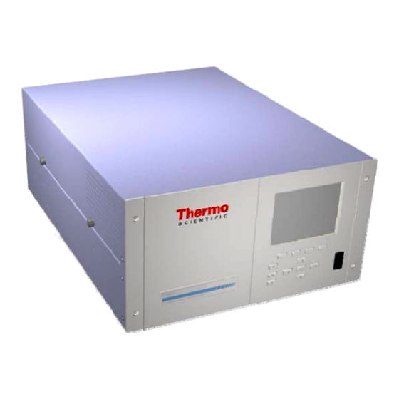
Thermo Scientific 48i Instruction Manual (321 pages)
Gas Filter Correlation CO Analyzer
Brand:
Thermo Scientific
| Category:
Measuring Instruments
| Size: 2.17 MB
Table of Contents
Weee Compliance
3
About this Manual
7
Table of Contents
11
Chapter 1 Introduction
25
Principle of Operation
26
Specifications
27
Figure 1-1. Model 48I Flow Schematic
27
Table 1-1. Model 48I Specifications
27
Table 1-2. Model 48I Optional Internal Oxygen Sensor Specifications
28
Chapter 2 Installation
29
Lifting
29
Unpacking and Inspection
29
Figure 2-1. Remove the Packing Material
30
Figure 2-2. Removing the Shipping Screws
30
Setup Procedure
31
Figure 2-3. Model 48I Rear Panel
32
Figure 2-4. Atmospheric Dump Bypass Plumbing
32
Connecting External Devices
33
Terminal Board PCB Assemblies
33
I/O Terminal Board
33
D/O Terminal Board
33
25-Pin Terminal Board
33
Figure 2-5. I/O Terminal Board Views
34
Table 2-1. I/O Terminal Board Pin Descriptions
34
Figure 2-6. D/O Terminal Board Views
35
Table 2-2. D/O Terminal Board Pin Descriptions
35
Figure 2-7. 25-Pin Terminal Board Views
36
Table 2-3. 25-Pin Terminal Board Pin Descriptions
36
Startup
38
Chapter 3 Operation
39
Display
39
Pushbuttons
40
Figure 3-1. Front Panel Display
40
Figure 3-2. Front Panel Pushbuttons
40
Soft Keys
41
Table 3-1. Front Panel Pushbuttons
41
Alphanumeric Entry Screen
42
Firmware Overview
42
Figure 3-3. Flowchart of Menu-Driven Firmware
43
Power-Up Screen
44
Run Screen
44
Custom Run Screens
45
Main Menu
46
Range Menu
46
Single Range Mode
47
Figure 3-4. Pin-Out of Rear Panel Connector in Single Range Mode
47
Table 3-2. Default Analog Outputs in Single Range Mode
47
Dual Range Mode
48
Figure 3-5. Pin-Out of Rear Panel Connector in Dual Range Mode
48
Auto Range Mode
49
Table 3-3. Default Analog Outputs in Dual Range Mode
49
Figure 3-6. Analog Output in Auto Range Mode
50
Figure 3-7. Pin-Out of Rear Connector in Auto Range Mode
50
Gas Units
51
Table 3-4. Default Analog Outputs in Auto Range Mode
51
CO Range
52
Table 3-5. Available Operating Ranges
52
Set Custom Ranges
53
Custom Ranges
53
Averaging Time
54
Calibration Factors Menu
54
CO Background
55
CO Coefficient
56
O Background
56
O Coefficient
57
O 2 Background
57
Reset User Calibration Defaults
58
Calibration Menu
58
O 2 Coefficient
58
Calibrate CO Background
59
Calibrate CO Coefficient
59
Zero/Span Check
60
Next Time
60
Period Hours
61
Total Duration Hour
61
Zero/Span/Purge Duration Minutes
61
Zero/Span Averaging Time
62
Zero/Span Ratio
62
Calibrate O Background
63
Calibrate O Coefficient
63
Instrument Controls Menu
63
Datalogging Settings
64
Select Srec/Lrec
65
View Logged Data
65
Number of Records
65
Date and Time
66
Erase Log
67
Select Content
67
Choose Field Data
67
Concentrations
68
Corrected Concentrations
68
Other Measurements
68
Analog Inputs
68
Other Measurements
69
Commit Content
70
Reset to Default Content
70
Configure Datalogging
71
Logging Period Min
71
Memory Allocation Percent
71
Data Treatment
72
Flag Status Data
72
Communication Settings
73
Serial Settings
73
Baud Rate
74
Data Bits
74
Parity
74
Stop Bits
74
RS-232/RS-485 Selection
75
Instrument ID
75
Gesytec Serial No
76
Communication Protocol
76
Streaming Data Configuration
77
Streaming Data Interval
78
Choose Stream Data Item
79
Other Measurements
80
TCP/IP Settings
81
IP Address
82
Host Name
83
Output Relay Settings
84
Instrument State
85
Non-Alarm
86
Logic State
87
Allow Over/Under Range
88
Select Range
89
Table 3-6. Analog Output Zero to Full-Scale Table
90
Choose Signal to Output
90
Table 3-7. Signal Type Group Choices
91
Analog Input Configuration
92
Units
93
Table Point
94
User Value
95
Pressure Compensation
96
O 2 Compensation
97
Date/Time
98
Diagnostics Menu
99
Voltages
100
I/O Board Voltages
101
Flow
102
Motor Speed
103
Analog Input Voltages
104
Test Analog Outputs
105
Contact Information
106
Internal Temperature
107
Bench Temperature
108
Sample Flow
109
Bias Voltage
110
AGC Intensity
111
Zero and Span Check
112
Concentration
113
O 2 Concentration
114
Min Trigger
115
Service Menu
116
Pressure Calibration
117
Calibrate Pressure Zero
118
Calibrate Pressure Span
118
Restore Default Pressure Calibration
118
Flow Calibration
119
Calibrate Flow Zero
119
Calibrate Flow Span
119
Restore Default Flow Calibration
120
Multi-Point Calibration
121
Calibrate Point 1/2/3
121
Coefficients
122
Default Coefficients
122
Preamp Board Calibration
122
Temperature Calibration
123
Analog Output Calibration
123
Analog Output Calibrate Zero
124
Analog Output Calibrate Full-Scale
124
Analog Input Calibration
125
Analog Input Calibrate Zero
125
Analog Input Calibrate Full-Scale
126
Dilution Ratio
127
Setup Run Screens
127
Edit Run Screen
128
Edit Title
128
Enabled
128
Number of Items
129
Concentrations
130
Corrected Concentrations
130
Other Measurements
130
Analog Inputs
130
Display Pixel Test
131
Other Measurements
131
Restore User Defaults
132
Password
132
Set Password
133
Lock Instrument
133
Lock/Unlock and Local/Remote Operation
133
Change Password
134
Remove Password
134
Unlock Instrument
134
Calibration
135
Equipment Required
135
CO Concentration Standard
135
Chapter 4 Calibration
135
Compression
136
Mixing Chamber
137
Figure 4-1. Calibration Flow Schematic
138
Zero Adjust
138
Calibration Frequency
140
HI and LO Multi-Point Calibration
141
References
143
Chapter 5 Preventive Maintenance
145
Replacement Parts
146
IR Source Replacement
147
Figure 5-1. Inspecting and Cleaning the Fan
148
Leak Test and Pump Check out
148
Leaks Across the Optional Zero/Span and Sample Solenoid Valves
149
Figure 5-2. Rebuilding the Pump (New Technology)
151
Assembly with New Diaphragm and Valve
152
Figure 5-3. Rebuilding the Pump
153
Chapter 6 Troubleshooting
155
Table 6-1. Troubleshooting - General Guide
156
Table 6-2. Troubleshooting - Alarm Messages
157
Figure 6-1. Board-Level Connection Diagram - Common Electronics
159
Figure 6-2. Board-Level Connection Diagram - Measurement System
160
Table 6-3. Motherboard Connector Pin Descriptions
161
Table 6-4. Measurement Interface Board Connector Pin Descriptions
166
Table 6-5. Front Panel Board Connector Pin Diagram
168
Table 6-6. I/O Expansion Board (Optional) Connector Pin Descriptions
170
Table 6-7. Digital Output Board Connector Pin Descriptions
171
Table 6-8. Pre-Amp Board Connector Pin Descriptions
173
Service Locations
174
Chapter 7 Servicing
175
Safety Precautions
177
Figure 7-1. Properly Grounded Antistatic Wrist Strap
178
Table 7-1. Model 48I Replacement Parts
178
Firmware Updates
178
Table 7-2. Model 48I Cables
180
Table 7-3. External Device Connection Components
180
Cable List
180
Figure 7-2. Component Layout
181
Figure 7-3. Removing the Measurement Case Assembly and Lowering the Partition Panel
182
Fuse Replacement
183
Fan/Filter Replacement
184
Figure 7-4. Replacing the Fan
185
IR Source Replacement
185
Figure 7-5. Replacing the IR Source
186
Filter Wheel Replacement
186
Figure 7-6. Removing the Motor
187
Chopper Motor Replacement
188
Optical Bench Replacement
189
Figure 7-7. Replacing the Optical Bench
190
Optical Switch Replacement
190
Figure 7-8. Replacing the Optical Switch (Inverted View)
191
Bench Heater Assembly Replacement
191
Detector/Preamplifier Assembly Replacement
192
Figure 7-9. Replacing the Detector/Preamplifier Assembly
193
Preamp Board Calibration
194
Figure 7-10. Replacing the Pump
195
Pressure Transducer Replacement
195
Figure 7-11. Replacing the Pressure Transducer
196
Pressure Transducer Calibration
196
Flow Transducer Replacement
198
Figure 7-12. Replacing the Flow Transducer
199
Flow Transducer Calibration
199
Capillary Cleaning or Replacement
200
Figure 7-13. Cleaning or Replacing the Capillary
201
Optional Zero/Span and Sample Solenoid Valve Replacement
201
Analog Output Testing
202
Figure 7-14. Rear Panel Analog Input and Output Pins
203
Table 7-4. Analog Output Channels and Rear Panel Pin Connections
204
Table 7-5. Analog Input Channels and Rear Panel Pin Connections
204
Analog Output Calibration
204
Analog Input Calibration
205
Calibrating the Input Channels to Full-Scale
206
Ambient Temperature Calibration
207
I/O Expansion Board (Optional) Replacement
208
Figure 7-15. Replacing the I/O Expansion Board (Optional)
209
Figure 7-16. Rear Panel Board Connectors
209
Internal O 2 Sensor (Optional) Replacement
210
Motherboard Replacement
211
Measurement Interface Board Replacement
212
Figure 7-17. Replacing the Measurement Interface Board
213
Front Panel Board Replacement
213
Figure 7-18. Replacing the Front Panel Board and the LCD Module
214
LCD Module Replacement
214
Service Locations
215
Chapter 8 System Description
217
Figure 8-1. Hardware Components
218
Optical Bench
218
Optical Pickup
219
Instrument Control
220
Electronics
221
Measurement Interface Board
222
Bench Heater Board
223
I/O Components
224
Analog Voltage Inputs (Optional)
225
Table 8-1. RS-232 DB9 Connector Pin Configuration
226
Serial Ports
226
Table 8-2. RS-485 DB9 Connector Pin Configuration
227
RS-485 Connection
227
Mounting Options
229
Figure 9-1. Flow Diagram, Internal O 2 Sensor
230
Internal Oxygen (O 2 ) Sensor
230
Alternate Sensor Calibration
231
Figure 9-2. Purge Housing Assembly
232
Internal Zero Air Scrubber
232
Calibration Note
233
Table 9-1. Cable Options
234
Table 9-2. Color Codes for 25-Pin and 37-Pin Cables
234
Table 9-3. Mounting Options
235
Figure 9-3. Rack Mount Option Assembly
236
Figure 9-4. Bench Mounting
237
Figure 9-5. EIA Rack Mounting
238
Figure 9-6. Retrofit Rack Mounting
239
Appendix A Warranty
241
Appendix B C-Link Protocol Commands
243
Commands
244
Table B-1. Command Response Error Descriptions
245
Table B-2. C-Link Protocol Commands
245
Table B-3. Averaging Times
252
Figure B-1. Flags Field
255
Alarms
256
Table B-4. Alarm Trigger Values
260
Datalogging
261
Table B-5. Record Output Formats
265
Table B-6. Stream Time Values
268
Keys/Display
275
Table B-7. Standard Ranges
277
Hardware Configuration
280
Table B-8. Contrast Levels
281
Communications Configuration
282
Table B-9. Reply Termination Formats
286
Table B-10. Allow Mode Command Values
288
Table B-11. Power up Mode Values
289
Table B-12. Set Layout Ack Values
289
Table B-13. Analog Current Output Range Values
290
Table B-14. Analog Voltage Output Range Values
291
Table B-15. Default Analog Output Channel Assignments
293
Record Layout Definition
295
Format Specifier for ASCII Responses
296
Text
297
Translation Table
298
Examples
299
Appendix C MODBUS Protocol
301
Function Codes
302
X05) Force (Write) Single Coil
307
Table C-1. Read Coils for 48I
308
MODBUS Parameters Supported
308
Table C-2. Read Registers for 48I
310
Table C-3. Write Coils for 48I
312
Reading a Write Coil
312
Serial Communication Parameters
313
TCP Communication Parameters
314
Block Checksum Characters <BCC>
315
Table D-1. Operating Status for Model 48I
319
Measurements Reported in Response to DA Command
319
Table D-2. Error Status for Model 48I
320
Advertisement
Thermo Scientific 48i Instruction Manual (297 pages)
Trace Level-Enhanced Gas Filter Correlation CO Analyzer
Brand:
Thermo Scientific
| Category:
Measuring Instruments
| Size: 3.01 MB
Table of Contents
Weee Compliance
3
About this Manual
5
Table of Contents
9
Chapter 1 Introduction
23
Principle of Operation
24
Specifications
25
Figure 1-1. Model 48I Trace Level-Enhanced
25
Table 1-1. Model 48I Trace Level-Enhanced Specifications
25
Chapter 2 Installation
27
Lifting
27
Unpacking and Inspection
27
Figure 2-1. Remove the Packing Material
28
Figure 2-2. Removing the Shipping Screws
28
Setup Procedure
29
Figure 2-3. Model 48I Trace Level-Enhanced Rear Panel
29
Figure 2-4. Atmospheric Dump Bypass Plumbing
30
Connecting External Devices
31
Terminal Board PCB Assemblies
31
I/O Terminal Board
31
D/O Terminal Board
31
25-Pin Terminal Board
31
Figure 2-5. I/O Terminal Board Views
32
Table 2-1. I/O Terminal Board Pin Descriptions
32
Figure 2-6. D/O Terminal Board Views
33
Table 2-2. D/O Terminal Board Pin Descriptions
33
Figure 2-7. 25-Pin Terminal Board Views
34
Table 2-3. 25-Pin Terminal Board Pin Descriptions
34
Startup
36
Chapter 3 Operation
37
Display
37
Pushbuttons
38
Figure 3-1. Front Panel Display
38
Figure 3-2. Front Panel Pushbuttons
38
Soft Keys
39
Table 3-1. Front Panel Pushbuttons
39
Software Overview
40
Figure 3-3. Flowchart of Menu-Driven Software
41
Power-Up Screen
42
Run Screen
42
Main Menu
43
Range Menu
44
Single Range Mode
44
Figure 3-4. Pin-Out of Rear Panel Connector in Single Range Mode
44
Dual Range Mode
45
Table 3-2. Default Analog Outputs in Single Range Mode
45
Auto Range Mode
46
Figure 3-5. Pin-Out of Rear Panel Connector in Dual Range Mode
46
Table 3-3. Default Analog Outputs in Dual Range Mode
46
Figure 3-6. Analog Output in Auto Range Mode
47
Figure 3-7. Pin-Out of Rear Connector in Auto Range Mode
48
Table 3-4. Default Analog Outputs in Auto Range Mode
48
Gas Units
49
CO Range
49
Set Custom Ranges
50
Table 3-5. Available Operating Ranges
50
Custom Ranges
51
Averaging Time
51
Calibration Factors Menu
52
CO Background
53
CO Coefficient
54
Reset User Calibration Default
54
Calibration Menu
55
Calibrate CO Background
55
Calibrate CO Coefficient
56
Zero/Span Check
56
Next Time
57
Period Hours
57
Zero/Span/Purge Duration Minutes
58
Zero/Span Averaging Time
59
Zero/Span Ratio
59
Instrument Controls Menu
59
Datalogging Settings
60
Select SREC/LREC
60
View Logged Data
60
Number of Records
61
Date and Time
62
Erase Log
62
Select Content
62
Choose Item Type
63
Concentrations
63
Other Measurements
63
Analog Inputs
63
Commit Content
65
Reset to Default Content
65
Configure Datalogging
66
Logging Period Min
66
Memory Allocation Percent
66
Data Treatment
67
Communication Settings
67
Baud Rate
68
Instrument ID
68
Communication Protocol
68
Choose Item Signal
70
Concentrations
70
Other Measurements
70
Analog Inputs
70
Streaming Data Interval
70
RS-232/RS-485 Selection
73
TCP/IP Settings
73
Use DHCP
73
IP Address
74
Netmask
74
Default Gateway
75
Host Name
75
I/O Configuration
75
Output Relay Settings
76
Logic State
76
Non-Alarm
78
Instrument State
79
Instrument Action
79
Select Output Range
80
Table 3-6. Analog Output Zero to Full-Scale Table
81
Choose Signal to Output
81
Table 3-7. Signal Type Group Choices
82
Analog Input Configuration
83
Units
84
Number of Table Points
85
User Value
86
Pressure Compensation
87
Service Mode
88
Diagnostics Menu
89
Voltages
90
I/O Board Voltages
91
Pressure
92
AGC Intensity
93
Analog Input Readings
94
Relay States
95
Instrument Configuration
96
Alarms Menu
97
Min and Max Internal Temperature Limits
98
Min and Max Bench Temperature Limits
99
Sample Flow
100
Bias Voltage
101
Min and Max Bias Voltage Limits
101
AGC Intensity
101
Min and Max AGC Intensity Limits
102
Motor Speed
102
Zero and Span Check
102
Max Zero and Span Offset
103
Zero and Span Auto Calibration
103
Scrubber Gas Concentration
104
Min and Max Scrubber Gas Concentration Limits
104
Scrubber Efficiency
104
Min and Max Scrubber Efficiency Limits
105
Concentration
105
Min Trigger Concentration
106
Min and Max Concentration Limits
106
Service Menu
107
Range Mode Select
107
Pressure Calibration
108
Calibrate Pressure Zero
108
Calibrate Pressure Span
109
Restore Default Pressure Calibration
109
Flow Calibration
109
Calibrate Flow Zero
110
Calibrate Flow Span
111
Restore Default Flow Calibration
111
Internal Set Temperature
112
Scrubber Test
112
Multi-Point Calibration
113
Calibrate Point 1/2/3
113
Coefficients
113
Default Coefficients
113
Password Menu
120
Change Password
121
Unlock Instrument
122
Chapter 4 Calibration
123
Equipment Required
124
Compression
125
Figure 4-1. Dilution System Schematic
126
Flow Meter(S) and Controller(S)
126
Mixing Chamber
127
Figure 4-2. Internal Zero and Span Valve Plumbing
128
External Connections
128
Figure 4-3. Plumbing Configuration for Mulit-Point External Calibration
129
Figure 4-4. Plumbing Configuration for Single-Point Internal Calibration
130
Pre-Calibration
130
Single Point Internal Calibration
131
Multi-Point External Calibration
132
Span Adjust
133
Calibration Curve
134
Span Check
135
Automatic Zero and Span Adjustment
136
References
137
Chapter 5 Preventive Maintenance
139
Replacement Parts
140
Capillary Cleaning or Replacement
141
Figure 5-1. Cleaning or Replacing the Capillaries
142
Cleaning the Optics
142
Figure 5-2. Inspection and Cleaning the Fan
143
Leak Test and Pump Check out
143
Leaks Across the Optional Zero/Span and Sample Solenoid Valves
144
Figure 5-3. Rebuilding the Pump
145
Safety Precautions
147
Table 6-1. Troubleshooting - Power-Up Failures
148
Table 6-2. Troubleshooting - Calibration Failures
149
Table 6-3. Troubleshooting - Measurement Failures
151
Table 6-4. Troubleshooting - Alarm Messages
153
Figure 6-1. Board-Level Connection Diagram - Common Electronics
155
Figure 6-2. Board-Level Connection Diagram - Measurement System
156
Table 6-5. Motherboard Connector Pin Descriptions
157
Table 6-6. Measurement Interface Board Connector Pin Descriptions
162
Table 6-7. Front Panel Board Connector Pin Diagram
164
Table 6-8. I/O Expansion Board (Optional) Connector Pin Descriptions
166
Table 6-9. Digital Output Board Connector Pin Descriptions
167
Table 6-10. Pre-Amp Board Connector Pin Descriptions
169
Service Locations
170
Chapter 7 Servicing
171
Safety Precautions
172
Figure 7-1. Properly Grounded Antistatic Wrist Strap
173
Firmware Updates
173
Table 7-1. Model 48I Trace Level-Enhanced Replacement Parts
174
Replacement Parts List
174
Table 7-2. Model 48I Trace Level-Enhanced Cables
175
Cable List
175
Figure 7-2. Component Layout
176
Table 7-3. External Device Connection Components
176
Figure 7-3. Removing the Measurement Bench and Lowering the Partition
177
Fuse Replacement
178
Figure 7-4. Replacing the Rear Panel Fan
179
Figure 7-5. Replacing the Bench Fan
180
Bench Fan Replacement
180
IR Source Replacement
181
Figure 7-6. Replacing the IR Source
182
Filter Wheel Replacement
182
Figure 7-7. Removing the Motor
183
Chopper Motor Replacement
184
Figure 7-8. Replacing the Optical Bench
185
Optical Bench Replacement
185
Optical Switch Replacement
186
Figure 7-9. Replacing the Optical Switch (Inverted View)
187
Bench Heater Assembly Replacement
187
Detector/Preamplifier Assembly Replacement
188
Figure 7-10. Replacing the Detector/Preamplifier Assembly
189
Preamp Board Calibration
190
Figure 7-11. Replacing the Pump
191
Pressure Transducer Replacement
191
Figure 7-12. Replacing the Pressure Transducer
192
Pressure Transducer Calibration
192
Figure 7-13. Replacing the Flow Transducer
194
Flow Transducer Replacement
194
Flow Transducer Calibration
195
Zero/Span and Sample Solenoid Valve Replacement
196
Analog Output Testing
197
Figure 7-14. Rear Panel Analog Input and Output Pins
198
Table 7-4. Analog Output Channels and Rear Panel Pin Connections
198
Analog Output Calibration
199
Analog Input Calibration
200
Table 7-5. Analog Input Channels and Rear Panel Pin Connections
200
Calibrating the Input Channels to Full-Scale
201
Ambient Temperature Calibration
202
I/O Expansion Board (Optional) Replacement
203
Figure 7-15. Replacing the I/O Expansion Board (Optional)
204
Figure 7-16. Rear Panel Board Connectors
204
Digital Output Board Replacement
204
Motherboard Replacement
205
Measurement Interface Board Replacement
206
Figure 7-17. Replacing the Measurement Interface Board
207
Front Panel Board Replacement
207
Figure 7-18. Replacing the Front Panel Board and the LCD Module
208
LCD Module Replacement
208
Service Locations
209
System Description
211
Figure 8-1. Hardware Components
212
Optical Bench
212
Optical Pickup
213
Instrument Control
214
Motherboard
215
Measurement Interface Board
216
Bench Heater Board
217
I/O Components
218
Analog Voltage Inputs (Optional)
219
Table 8-1. RS-232 DB Connector Pin Configurations
220
Table 8-2. RS-485 DB Connector Pin Configuration
220
RS-232 Connection
220
Ethernet Connection
221
Optional Equipment
223
Table 9-1. Cable Options
224
Cables
224
Table 9-2. Color Codes for 25-Pin and 37-Pin Cables
225
Figure 9-1. Rack Mount Option Assembly
226
Table 9-3. Mounting Options
226
Figure 9-2. Bench Mounting
227
Figure 9-3. EIA Rack Mounting
228
Figure 9-4. Retrofit Rack Mounting
229
Appendix A Warranty
231
Appendix B C-Link Protocol Commands
233
Commands
234
Table B-1. C-Link Protocol Commands
235
Table B-2. Averaging Times
240
Measurements
240
Figure B-1. Flags
243
Alarms
243
Table B-3. Alarm Trigger Values
247
Diagnostics
247
Datalogging
248
Table B-4. Record Output Formats
251
Table B-5. Stream Time Values
255
Calibration
255
Keys/Display
258
Table B-6. Standard Ranges
260
Measurement Configuration
260
Table B-7. Contrast Levels
263
Hardware Configuration
263
Communications Configuration
265
Table B-8. Reply Termination Formats
267
Table B-9. Analog Current Output Range Values
269
I/O Configuration
269
Table B-10. Analog Voltage Output Range Values
270
Table B-11. Default Output Assignment
271
Record Layout Definition
273
Format Specifier for Binary Responses
274
Text
275
Translation Table
276
Examples
277
Appendix C MODBUS Protocol
279
TCP Communication Parameters
280
Function Code
281
X03/0X04) Read Holding Registers / Read Input Registers
283
X05) Force (Write) Single Coil
285
Table C-1. Read Coils for 48I Trace Level-Enhanced
286
MODBUS Parameters Supported
286
Table C-2. Read Registers for 48I Trace Level-Enhanced
287
Table C-3. Write Coils for 48I Trace Level-Enhanced
288
Appendix D Geysitech (Bayern-Hessen) Protocol
289
TCP Communication Parameters
290
Block Checksum <BCC>
291
Measurements Reported in Response to DA Command
294
Table D-1. Operating Status for Model 48I Trace Level-Enhanced
295
Table D-2. Error Status for Model 48I Trace Level-Enhanced
295
Advertisement
Related Products
Thermo Scientific 48iQTL
Thermo Scientific 48iQ
Thermo Scientific 42i
Thermo Scientific 43i
Thermo Scientific 42iQHL
Thermo Scientific 42iQLS
Thermo Scientific 42iQTL
Thermo Scientific 43iQTL
Thermo Scientific 48000
Thermo Scientific 4344
Thermo Scientific Categories
Laboratory Equipment
Measuring Instruments
Accessories
Refrigerator
Freezer
More Thermo Scientific Manuals
Login
Sign In
OR
Sign in with Facebook
Sign in with Google
Upload manual
Upload from disk
Upload from URL