Sign In
Upload
Manuals
Brands
Thermo Scientific Manuals
Measuring Instruments
43i
Thermo Scientific 43i Manuals
Manuals and User Guides for Thermo Scientific 43i. We have
1
Thermo Scientific 43i manual available for free PDF download: Instruction Manual
Thermo Scientific 43i Instruction Manual (312 pages)
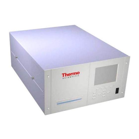
Pulsed Fluorescence SO2 Analyzer
Brand:
Thermo Scientific
| Category:
Measuring Instruments
| Size: 2 MB
Table of Contents
Weee Compliance
3
About this Manual
5
Table of Contents
9
Chapter 1 Introduction
23
Principle of Operation
24
Specifications
25
Figure 1-1. Model 43I Trace Level-Enhanced Flow Schematic
25
Table 1-1. Model 43I Trace Level-Enhanced Specifications
25
Table 1-2. Model 43I Trace Level-Enhanced Optional Permeation Oven Specifications
27
Installation
29
Lifting
29
Unpacking and Inspection
29
Chapter 2 Installation
29
Figure 2-1. Remove the Packing Material
30
Figure 2-2. Removing the Shipping Screws
30
Setup Procedure
31
Figure 2-3. Rear Panel
32
Connecting External Devices
33
Terminal Board PCB Assemblies
33
I/O Terminal Board
33
D/O Terminal Board
33
25-Pin Terminal Board
33
Figure 2-4. Atmospheric Dump Bypass Plumbing
33
Figure 2-5. I/O Terminal Board Views
34
Table 2-1. I/O Terminal Board Pin Descriptions
34
Figure 2-6. D/O Terminal Board Views
35
Table 2-2. D/O Terminal Board Pin Descriptions
35
Figure 2-7. 25-Pin Terminal Board Views
36
Table 2-3. 25-Pin Terminal Board Pin Descriptions
36
Startup
37
Chapter 3 Operation
39
Display
40
Figure 3-1. Front Panel Display
40
Pushbuttons
41
Figure 3-2. Front Panel Pushbuttons
41
Table 3-1. Front Panel Pushbuttons
41
Soft Keys
42
Software Overview
42
Figure 3-3. Flowchart of Menu-Driven Software
43
Power-Up Screen
44
Run Screen
44
Main Menu
44
Range Menu
45
Alarms
45
Single Range Mode
46
Figure 3-4. Pinout of Rear Panel Connector in Single Range Mode
46
Table 3-2. Default Analog Outputs in Single Range Mode
46
Dual Range Mode
47
Figure 3-5. Pinout of Rear Panel Connector in Dual Range Mode
47
Table 3-3. Default Analog Outputs in Dual Range Mode
47
Autorange Mode
48
Figure 3-6. Analog Output in Autorange Mode
49
Figure 3-7. Pin-Out of Rear Panel Connector in Auto-Range Mode
49
Gas Units
50
Table 3-4. Default Analog Outputs in Auto Range Mode
50
SO Range
51
Table 3-5. Standard Ranges
51
So2 Range:
51
Set Custom Ranges
52
Custom Ranges
52
Averaging Time
53
Calibration Factors Menu
53
SO 2 Background
54
SO Span Coefficient
55
Reset User Calibration Default
56
Calibration Menu
56
Calibrate so Background
56
Calibrate so Coefficient
57
Zero/Span Check Menu
57
Next Time
58
Period Hours
58
Zero/Span/Purge Duration Minutes
59
Zero/Span Averaging Time
59
Zero/Span Ratio
59
Instrument Controls Menu
60
Flash Lamp
60
Datalogging Settings
61
Select SREC/LREC
61
View Logged Data
61
Number of Records
62
Date and Time
62
Erase Log
63
Select Content
63
Concentrations
64
Choose Item Type
64
Other Measurements
65
Commit Content
66
Reset to Default Content
66
Configure Datalogging
67
Logging Period Min
67
Memory Allocation Percent
67
Data Treatment
67
Communication Settings
68
Baud Rate
69
Instrument ID
69
Communication Protocol
70
Streaming Data Configuration
70
Streaming Data Interval
71
Choose Item Signal
71
Concentrations
71
Other Measurements
72
Analog Inputs
72
RS-232/RS-485 Selection
73
TCP/IP Settings
73
Use DHCP
73
IP Address
74
Netmask
74
Gateway
75
Host Name
75
I/O Configuration
75
Output Relay Settings
75
Digital Input Settings
75
Logic State
76
Instrument State
76
Instrument Action
79
Analog Output Configuration
79
Select Output Range
80
Table 3-6. Analog Output Zero to Full Scale Values
81
Choose Signal to Output
82
Table 3-7. Signal Types Group Choices
82
Analog Input Configuration
83
Descriptor
83
Units
83
Decimal Places
84
Number of Table Points
84
Volts
85
User Value
85
Temperature Compensation
86
Pressure Compensation
86
Screen Contrast
86
Service Mode
87
Date/Time
87
Diagnostics Menu
88
Program Versions
88
Voltages
88
Motherboard Voltages
89
Interface Board Voltages
89
I/O Board Voltages
90
Temperatures
90
Pressure
90
Sample Flow
91
Lamp Intensity
91
Optical Span Test
91
Analog Input Readings
92
Analog Input Voltages
92
Digital Inputs
92
Relay States
93
Test Analog Outputs
93
Set Analog Outputs
94
Instrument Configuration
94
Contact Information
95
Alarms Menu
95
Internal Temperature
96
Chamber Temperature
97
Min and Max Pressure Limits
98
Sample Flow
98
Lamp Intensity
99
Lamp Voltage
100
Min and Max Lamp Voltage Limits
100
Zero and Span Check
100
Max Zero and Span Offset
101
Zero and Span Auto Calibration
101
SO 2 Concentration
101
Min and Max so
102
Min Trigger
102
Concentration Limits
102
Service Menu
103
Flash Voltage Adjustment
103
Initial Flash Reference
104
PMT Voltage Adjustment
104
Range Mode Select
105
Pressure Calibration
105
Set Defaults
105
Calibrate Pressure Zero
106
Calibrate Pressure Span
106
Restore Default Pressure Calibration
107
Flow Calibration
107
Calibrate Flow Zero
108
Calibrate Flow Span
108
Restore Default Flow Calibration
108
Input Board Test
109
Temperature Calibration
109
Analog Output Calibration
109
Analog Output Calibrate Zero
110
Analog Output Calibrate Full-Scale
111
Analog Input Calibration
111
Analog Input Calibration Zero
112
Permeation Oven Settings
113
Calibrate Gas Thermistor
113
Water Bath
113
Resistor
114
Calibrate Oven Thermistor
114
Permeation Oven Setpoint
114
Low and High Points
115
Set Defaults
115
Factory Calibrate Gas Thermistor
115
Factory Calibrate Oven Thermistor
116
Low and High Points
116
Dilution Ratio
117
Display Pixel Test
117
Restore User Defaults
118
Password
118
Set Password
118
Lock Instrument
119
Change Password
119
Remove Password
120
Unlock Instrument
120
Chapter 4 Calibration
121
Zero Gas Generation
121
Commercial Heatless Air Dryers
121
Absorbing Column
122
Calibration Gas Generation
122
Cylinder Gas Dilution
122
Commercial Precision Dilution Systems
123
Permeation Tube System
123
Figure 4-1. Cylinder Gas Dilution System
123
Commercial Permeation Systems
124
Figure 4-2. Permeation Tube System
124
Multi-Point Calibration
125
Multipoint Calibration in Dual/Auto Range Mode
127
Zero/Span Check
130
Chapter 5 Preventive Maintenance
134
Replacement Parts
134
Cleaning the Outside Case
134
Visual Inspection and Cleaning
134
Cleaning the Mirrors
134
Capillary Inspection and Replacement
135
Figure 5-1. Inspecting and Replacing the Capillary
135
Fan Filter Inspection and Cleaning
136
Sample Particulate Filter Inspection
137
Lamp Voltage Check
137
Figure 5-1. Inspecting and Cleaning the Fan
137
Leak Test
138
Pump Rebuilding
138
Figure 5-2. Rebuilding the Pump
139
Chapter 6 Troubleshooting
141
Safety Precautions
141
Troubleshooting Guides
141
Table 6-1. Troubleshooting - Power-Up Failures
141
Table 6-2. Troubleshooting - Calibration Failures
143
Table 6-3. Troubleshooting - Measurement Failures
145
Table 6-4. Troubleshooting - Alarm Messages
148
Board-Level Connection Diagrams
150
Figure 6-1. Board-Level Connection Diagram - Common Electronics
150
Figure 6-2. Board-Level Connection Diagram - Measurement System
151
Connector Pin Descriptions
152
Table 6-5. Motherboard Connector Pin Descriptions
152
Table 6-6. Measurement Interface Board Connector Pin Descriptions
156
Table 6-7. Front Panel Board Connector Pin Diagram
159
Table 6-8. I/O Expansion Board (Optional) Connector Pin Descriptions
161
Table 6-9. Digital Output Board Connector Pin Descriptions
162
Table 6-10. Input Board Connector Pin Descriptions
163
Service Locations
164
Table 6-11. Flash Trigger Pack Pin Descriptions
164
Table 6-12. Flash Intensity Assembly Pin Descriptions
164
Chapter 7 Servicing
165
Safety Precautions
165
Firmware Updates
166
Accessing the Service Mode
166
Figure 7-1. Properly Grounded Antistatic Wrist Strap
166
Replacement Parts List
167
Table 7-1. Replacement Parts
167
Cable List
168
Table 7-2. Model 43I Trace Level-Enhanced Cables
168
External Device Connection Components
169
Table 7-3. External Device Connection Components
169
Figure 7-2. Model 43I Trace Level-Enhanced Component Layout
170
Removing the Measurement Bench and Lowering the Partition Panel
171
Fuse Replacement
172
Pump Replacement
172
Fan Replacement
174
Optical Bench Replacement
175
Cleaning the Mirrors
176
Flash Lamp Replacement
176
Flash Lamp Voltage Adjustment
178
Flash Trigger Assembly Replacement
178
Flash Intensity Assembly Replacement
179
Photomultiplier Tube Replacement
180
PMT High Voltage Power Supply Replacement
181
PMT Voltage Adjustment
183
DC Power Supply Replacement
184
Analog Output Testing
185
Table 7-4. Analog Output Channels and Rear Panel Pin Connections
186
Analog Output Calibration
187
Table 7-5. Analog Input Channels and Rear Panel Pin Connections
187
Analog Input Calibration
188
Calibrating the Input Channels to Zero Volts
188
Calibrating the Input Channels to Full Scale
189
Pressure Transducer Assembly Replacement
190
Pressure Transducer Calibration
191
Flow Transducer Replacement
193
Flow Transducer Calibration
194
Heater Assembly Replacement
196
Kicker Replacement
197
Thermistor Replacement
198
Ambient Temperature Calibration
199
Input Board Replacement
200
I/O Expansion Board (Optional) Replacement
201
Motherboard Replacement
204
Digital Output Board Replacement
204
Measurement Interface Board Replacement
205
Front Panel Board Replacement
206
LCD Module Replacement
207
Service Locations
208
Chapter 8 System Description
209
Hardware
209
Hydrocarbon Kicker
210
Optics
210
Figure 8-1. Hardware Components
210
Flash Lamp
211
Condensing Lens
211
Mirror Assembly
211
Relay Lens
211
Light Baffle
211
Reaction Chamber
211
Bandpass Filter
212
Photomultiplier Tube
212
Photodetector
212
Flow Sensor
212
Pressure Transducer
212
Capillary
212
Vacuum Pump
212
Software
212
Instrument Control
212
Monitoring Signals
213
Measurement Calculations
213
Output Communication
213
Electronics
214
Motherboard
214
External Connectors
214
Internal Connectors
215
Measurement Interface Board
215
Measurement Interface Board Connectors
215
Flow Sensor Assembly
215
Pressure Sensor Assembly
216
Bench Heater
216
PMT Power Supply Assembly
216
Diagnostic LED
216
Input Board
216
Digital Output Board
216
Front Panel Connector Board
216
Flash Trigger Board
217
Flash Intensity Board
217
I/O Expansion Board (Optional)
217
I/O Components
217
Analog Voltage Outputs
217
Analog Current Outputs (Optional)
218
Analog Voltage Inputs (Optional)
218
Digital Relay Outputs
218
Digital Inputs
219
Serial Ports
219
RS-232 Connection
219
Ethernet Connection
220
Table 8-1. RS-232 DB Connector Pin Configurations
220
Table 8-2. RS-485 DB Connector Pin Configuration
220
RS-485 Connection
220
External Accessory Connector
221
Internal Zero/Span and Sample Valves
223
Chapter 9 Optional Equipment
223
Internal Permeation Span Source
223
Permeation Tube Installation
224
Figure 9-1. Internal Permeation Span Source Flow Diagram
224
Computation of Concentrations
225
Oven Installation and Configuration
225
Permeation Tube Oven Calibration
227
Setting Perm Oven Temperature
227
Figure 9-2. Cal Oven Therm Resistor Screen
227
Setting Temperature with Water Bath
228
Figure 9-3. Cal Gas Therm Bath Screen
228
Setting Temperature with Known Resistance
229
Determining Permeation Rate by Weight Loss
229
Figure 9-4. Cal Gas Therm Resistor Screen
229
Determining Release Rate by Transfer Standard
230
Teflon Particulate Filter
231
I/O Expansion Board Assembly
231
25-Pin Terminal Board Assembly
231
Terminal Block and Cable Kits
231
Cables
232
Table 9-1. Cable Options
232
Table 9-2. Color Codes for 25-Pin and 37-Pin Cables
232
Mounting Options
233
Table 9-3. Mounting Options
233
Figure 9-5. Rack Mount Option Assembly
234
Figure 9-6. Bench Mounting
235
Figure 9-7. EIA Rack Mounting
236
Figure 9-8. Retrofit Rack Mounting
237
Appendix A Warranty
239
Appendix B C-Link Protocol Commands
241
Instrument Identification Number
241
Commands
242
Accessing Streaming Data
242
Entering Units in PPB
242
Table B-1. C-Link Protocol Commands
242
Measurements
247
Table B-2. Averaging Times
248
Figure B-1. Flags
250
Alarms
251
Diagnostics
254
Table B-3. Alarm Trigger Values
254
Datalogging
256
Table B-4. Record Output Formats
259
Calibration
263
Table B-5. Stream Time Values
263
Keys/Display
266
Measurement Configuration
267
Table B-6. Standard Ranges
268
Table B-7. Extended Ranges
268
Hardware Configuration
271
Table B-8. Contrast Level
272
Communications Configuration
274
Table B-9. Reply Termination Formats
277
I/O Configuration
278
Table B-10. Analog Current Output Range Values
279
Table B-11. Analog Voltage Output Range Values
280
Table B-12. Default Output Assignment
281
Record Layout Definition
283
Format Specifier for ASCII Responses
283
Format Specifier for Binary Responses
284
Format Specifier for Front-Panel Layout
284
Text
285
Value String
285
Value Source
285
Alarm Information
285
Translation Table
285
Selection Table
286
Examples
286
Appendix Cmodbus Protocol
289
Serial Communication Parameters
289
TCP Communication Parameters
289
Application Data Unit Definition
290
MBAP Header
290
Function Code
291
Data
291
Error Check
291
Function Codes
291
(0X01/0X02) Read Coils / Read Inputs
291
(0X03/0X04) Read Holding Registers / Read Input Registers
293
(0X05) Force (Write) Single Coil
295
MODBUS Commands Supported
296
Table C-1. Read Registers for 43I Trace Level-Enhanced
296
Table C-2. Write Coils for 43I Trace Level-Enhanced
297
Table C-3. Read Coils for 43I Trace Level-Enhanced
298
Serial Communication Parameters
301
Appendix D Geysitech (Bayern-Hessen) Protocol
301
TCP Communication Parameters
302
Instrument Address
302
Abbreviations Used
302
Basic Command Structure
302
Block Checksum <BCC
303
Geysitech Commands
303
Instrument Control Command (ST
303
Data Sampling/Data Query Command (DA
304
Measurements Reported in Response to DA Command
306
Single Range Mode
306
Dual/Auto Range Mode
306
Operating and Error Status
307
Table D-1. Operating Status for Model 43I Trace Level-Enhanced
307
Table D-2. Error Status for Model 43I Trace Level-Enhanced
307
Appendix E Standards for Trace Level Analyzers
309
Advertisement
Advertisement
Related Products
Thermo Scientific 43iQ
Thermo Scientific 43iQTL
Thermo Scientific 49i
Thermo Scientific 410i
Thermo Scientific 48iQTL
Thermo Scientific 49iQ
Thermo Scientific 42iQ
Thermo Scientific Nicolet 4700
Thermo Scientific 42iQD
Thermo Scientific 410iQ
Thermo Scientific Categories
Laboratory Equipment
Measuring Instruments
Freezer
Accessories
Refrigerator
More Thermo Scientific Manuals
Login
Sign In
OR
Sign in with Facebook
Sign in with Google
Upload manual
Upload from disk
Upload from URL