Sign In
Upload
Manuals
Brands
Thermo Scientific Manuals
Measuring Instruments
42iQLS
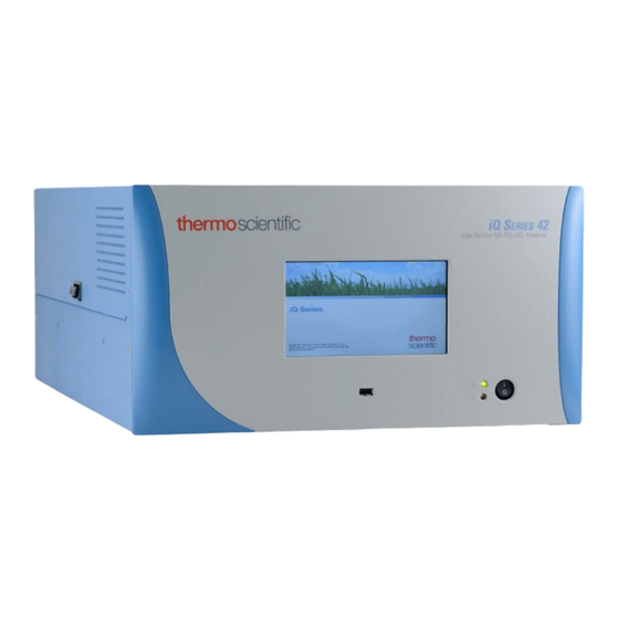
Thermo Scientific 42iQLS Manuals
Manuals and User Guides for Thermo Scientific 42iQLS. We have
1
Thermo Scientific 42iQLS manual available for free PDF download: Instruction Manual
Thermo Scientific 42iQLS Instruction Manual (318 pages)
Low Source NO-NO2-NOx Analyzer
Brand:
Thermo Scientific
| Category:
Measuring Instruments
| Size: 10 MB
Table of Contents
Table of Contents
3
Chapter 1 Introduction
9
Iq Series Instrument Platform
9
Figure 1-1. 42Iqls Front
10
Principle of Operation
11
Figure 1-2. 42Iqls Flow Schematic
12
Figure 1-3. 42Iqls Flow Schematic with Zero Span
12
Specifications
13
Table 1-1. 42Iqls Specifications
13
Table 1-2. 42Iqls Optional Internal Oxygen Sensor Specifications
14
Dimensions
15
Figure 1-4. Bench Mount Assembly (Dimensions in Inches [MM])
15
Figure 1-5. Rack Mount Assembly (Dimensions in Inches [MM])
16
Figure 1-6. Rack Mount Requirements
17
Installation and Setup
19
Unpacking and Inspection
19
Cover Removing and Replacing
20
Figure 2-1. Removing the Cover
20
Mounting Options
21
Bench Mount
21
Figure 2-2. Installing Feet
21
Rack Mount
22
Figure 2-3. Removing the Front Panel
22
Figure 2-4. Installing Ears and Handles
23
Setup Procedure
24
Figure 2-5. 42Iqls Rear Panel
25
Figure 2-6. Atmospheric Dump Bypass Plumbing
25
Startup
26
Figure 2-7. Front Panel and Touch Screen Display
26
Chapter 3 Operation
27
Instrument Display
27
Main Menus and Keypads
31
Numeric Keypad
32
Alphanumeric Keypad
33
Calibration
35
Calibrate Backgrounds
35
Calibrate NO and NO Background
37
Calibrate Span Coefficients
39
Calibrate NO, NO
41
Calibrate O 2 Span Coefficient
46
Advanced Calibration
47
Manual Calibration
48
Manual O Calibration
56
2-Point O Calibration
58
Calibration History
60
Data
61
View Data Log (Last Hour)
62
View Data Log (Last 24 Hours)
63
View Data Log (User Defined Time)
64
Advanced Data Setup
66
Data Logging Setup
67
Select Data Logging Variables
68
Streaming Data Setup
69
Select Streaming Variables
70
Settings
71
Health Check
72
Status and Alarms
73
Predictive Diagnostics
97
Maintenance
98
Preventive Maintenance
99
Change Part
101
Maintenance History
102
File Sharing and Support
103
Iq360
104
Measurement Settings
107
Averaging Time
108
Range Mode Selection
111
Range Settings
113
Gas Mode
116
Gas Units
117
Advanced Measurement Settings
118
Communications
128
Wired TCP/DHCP
130
Analog I/O
133
Digital I/O
134
Email Server (SMTP)
135
Bayern Hessen Settings
136
Instrument Settings
138
Instrument Setpoints
140
Alarm Setpoints
141
Display Setup
143
Clock
144
Time Zone
148
Configuration
152
Security Access Levels
153
Change Security to View Only Access
155
Change Full Access Security Password
156
USB Drive
158
Firmware Update Via USB Drive
159
Download Data to USB Drive
160
Change USB Password
163
User Contact Information
165
Update Bootloader
166
Chapter 4 Calibration
167
Equipment Required
168
Zero Gas Generator
168
Compression
168
Drying
168
Oxidation
168
Scrubbing
169
Gas Phase Titrator
169
Flow Controllers
169
Pressure Regulator
169
Table 4-1. Scrubbing Materials
169
Ozone Generator
170
Diverter Valve
170
Reaction Chamber
170
Mixing Chamber
170
Figure 4-1. GPT System
170
Output Manifold
171
Reagents
171
NO Concentration Standard
171
Assaying a Working NO Standard against a NIST-Traceable NO
171
Standard
171
Zero Air
172
Dynamic Parameter Specifications for Gas Titrator
172
Determining GPT System Flow Conditions
173
Pre-Calibration
174
Calibration
175
Connect GPT Apparatus to the Analyzer
176
Adjust Instrument Gain
176
Set NO and NO
176
Calibrate the NO Channel to the NO Calibration Gas
176
Backgrounds to Zero
177
Alternative Calibration Procedure Using NO Permeation Tube
181
Set NO and NO Background to Zero
182
Calibrate NO Low
183
Calibrate NO X Low
183
Calibrate NO 2 Low
183
Calibrate NO High
184
Calibrate NO X High
185
Calibrate NO 2 High
185
Zero and Span Check
186
Manual Calibration
187
Adjust NO and NO Backgrounds
188
Adjust Span Coefficient
189
Zero/Span Schedule
190
Next Time
190
Period
190
Zero/Span/Purge Duration Minutes
191
Schedule Averaging Time
191
Background Calibration and Span Calibration
191
Zero/Span Ratio
191
Chapter 5 Maintenance
193
Safety Precautions
193
Fan Filter Inspection and Cleaning
193
Thermoelectric Cooler Fins Inspection and Cleaning
194
Capillaries Inspection and Replacement
195
Figure 5-1. Inspecting and Replacing the Capillaries
195
Pump Rebuilding
197
Figure 5-2. Dual Stage Pump
197
Figure 5-3. Pump Rebuilding
199
Leak Test
200
Chapter 6 Troubleshooting
201
Safety Precautions
201
Troubleshooting Guide
201
Table 6-1. 42Iqls Troubleshooting Guide
201
Chapter 7 Servicing
207
Safety Precautions
207
Figure 7-1. Properly Grounded Antistatic Wrist Strap
208
Firmware Updates
209
Replacement Parts List
209
Figure 7-2. 42Iqls Component Layout Top View
210
Figure 7-3. 42Iqls Component Layout Side View
210
Fuse Replacement
211
Figure 7-4. Replacing the Fuses
211
Filter Replacement
212
Figure 7-5. Start with Top Right Corner of Fan Cover
212
Figure 7-6. Removing the Fan Cover
212
Fan Replacement
213
Figure 7-7. Unplugging the Fan Cable
213
Figure 7-8. Replacing the Fan
214
Measurement Side Removal and Replacing
215
Figure 7-9. Unplugging the Fan Cable
215
Figure 7-10. Unplugging the DMC Cable
216
Figure 7-11. Unfasten Hardware Front for Measurement Side Removal
216
Figure 7-12. Unfasten Hardware Rear for Measurement Side Removal
217
LCD Module Replacement
218
Figure 7-13. Replacing the LCD Module
218
Figure 7-14. Remove Electrical Cables from LCD
219
I/O Replacement
220
Figure 7-15. I/O Replacement, Arm
220
Figure 7-16. I/O Replacement, Remove Board
220
Figure 7-17. I/O Replacement, Install
221
Figure 7-18. I/O Replacement, Close Arm Alignment
221
Peripherals Support Board and System Controller Board Replacement
222
Figure 7-19. Replacing the Peripherals Support Board
222
DMC Pressure and Flow Board
223
Figure 7-20. Flow Pressure Board, Disconnect DMC Cable
223
Figure 7-21. Flow Pressure Board, Screws
224
Pump Replacement
225
Figure 7-22. Remove Pump, Disconnect and Unfasten
226
Figure 7-23. Pump Removal, Keyway
227
Figure 7-24. Pump Replacing, Unfasten Screws
228
Power Supply Replacement
229
Figure 7-25. Removing Power Supply
229
Figure 7-26. Replacing Power Supply
230
Step POL Board Replacement
231
Figure 7-27. Unplug and Unfasten Step POL Board
231
Figure 7-28. Clear Partition Keyway Step POL Board
232
Figure 7-29. Step POL Board 1 Switch Settings
233
Figure 7-30. Step POL Board 2 Switch Settings
233
DMC PMT Cooler and Reaction Chamber Replacement
234
PMT Cooler Shroud Removal
234
Figure 7-31. Remove PMT Cooler Shroud
235
PMT Cooler Board Replacement
236
Figure 7-32. Remove DMC PMT Cooler
236
Figure 7-33. Remove PMT Cooler Board
237
Reaction Chamber Cleaning And/Or Removal
238
Figure 7-34. Photo Reaction Chamber Cleaning, Electrical
238
Figure 7-35. Photo Reaction Chamber Cleaning, Hardware
239
Figure 7-36. Photo Reaction Chamber Cleaning, Window
240
Photomultiplier Tube (PMT) Replacement
241
Figure 7-37. PMT Tube Replace-Elec-Pt1
241
Figure 7-38. Removing the Access Panel, Starting Point
242
Figure 7-39. Access Cover
242
Figure 7-40. PMT Tube Replace-Screws
243
DMC Converter Replacement
244
Figure 7-41. Converter DMC Assembly Remove
244
Converter Assembly Board Replacement
245
Figure 7-42. Converter Assembly Remove Bd
245
Converter Cartridge Heater Replacement
246
Figure 7-43. Converter Assembly Replace Heater
247
DMC Ozonator
248
Ozonator and Transformer Removal
248
Figure 7-44. HVPS, Electrical
248
Figure 7-45. HVPS Remove
249
Transformer Replacement
250
Figure 7-46. Replace Ozonator
250
Ozonator and Transformer Board Replacement
251
Figure 7-47. Replace Transformer
251
Flow Switch Replacement
252
Figure 7-48. HPVS Remove Bd
252
Ammonia Scrubber Replacement
253
Figure 7-49. Flow Switch Remove
253
Figure 7-50. Remove Ammonia Scrubber
254
Optional Manifold Replacement
255
Figure 7-52. Replacing the Manifold Pt 2
256
Figure 7-53. Replacing the Manifold Pt 3
256
Optional Solenoid Valves Removal
257
Figure 7-54. Mode-Lag-Perm Electrical Connection
257
Figure 7-55. Mode-Lag-Perm Hardware, Plumbing
258
Optional DMC Oxygen Sensor
259
Oxygen Sensor Removal
259
Oxygen Sensor Board Replacement
262
Figure 7-60. Replacing the Oxygen Sensor DMC Board
262
Oxygen Sensor Capillary Replacement
264
Figure 7-62. Replacing the Oxygen Sensor Capillary
264
Oxygen Sensor Replacement
266
Figure 7-64. Replacing the Oxygen Sensor
266
Oxygen Sensor DMC Install
267
Figure 7-65. Installing the Oxygen Sensor DMC
267
Chapter 8 System Description
269
Reaction Chamber DMC
270
Optical Filter
270
Photomultiplier Tube
270
Photomultiplier Tube Cooler
270
Ozonator
270
Ozonator Flow Switch
270
Ozonator Permeation Dryer
271
Common Electronics
271
Figure 8-1. Common System Interconnect Diagram
272
Figure 8-2. 42Iqls System Interconnect Diagram
273
Power Supply
274
Front Panel
274
System Controller Board
274
Backplane Board
274
Peripherals Support System
275
Fan
275
Step POL Board
275
Sample Pump
275
Mode Solenoid
275
Flow/Pressure DMC
276
Firmware
276
Oxygen Sensor (Optional)
276
Chapter 9 Optional Equipment
277
Connecting External Devices
277
Figure 9-1. I/O Expansion Replacement Boards
277
Communication Board
278
RS-232/RS-485 Port
278
Figure 9-2. RS-232/RS-485 Port
278
Table 9-1. RS-232/RS-485 Port Terminal Assignment
278
External Accessory Port
279
Figure 9-3. RS-485 External Accessory Port
279
Table 9-2. RS-485 External Accessory Port Terminal Assignment
279
Analog I/O Board
280
Analog Voltage Inputs
280
Figure 9-4. Analog Voltage Inputs
280
Table 9-3. Analog Voltage Inputs Assignment
280
Analog Voltage Outputs
281
Figure 9-5. Analog Voltage and Current
281
Analog Output Calibration
282
Table 9-4. Analog Voltage and Current Assignment
282
Digital I/O Board
287
Digital Inputs
287
Figure 9-6. Digital Inputs
287
Table 9-5. Digital Inputs Terminal Assignment
288
Digital Relay Switches
289
Figure 9-7. Digital Relay Switches
289
Table 9-6. Digital Relay Switch Assignment
290
Valve Driver Outputs
291
Figure 9-8. Valve Driver Outputs
291
Table 9-7. Valve Driver Outputs Assignment
292
Internal Zero/Span and Sample Valves
293
Figure 9-9. Flow Diagram, Zero/Span Option
293
Internal Oxygen (O ) Sensor
294
Figure 9-10. 42Iqls Flow Schematic with Internal O
294
To-NO Converter
295
PTFE Particulate Filter
295
Appendix A Safety, Warranty, and WEEE
297
Safety
297
Safety and Equipment Damage Alerts
297
Warranty
298
WEEE Compliance
300
WEEE Symbol
300
List of Figures
301
GNU Lesser General Public License
305
Advertisement
Advertisement
Related Products
Thermo Scientific 42i
Thermo Scientific 42iQHL
Thermo Scientific 42iQ
Thermo Scientific 42iQTL
Thermo Scientific 42iQD
Thermo Scientific 49i
Thermo Scientific 410i
Thermo Scientific 48iQTL
Thermo Scientific 49iQ
Thermo Scientific Nicolet 4700
Thermo Scientific Categories
Laboratory Equipment
Measuring Instruments
Accessories
Freezer
Refrigerator
More Thermo Scientific Manuals
Login
Sign In
OR
Sign in with Facebook
Sign in with Google
Upload manual
Upload from disk
Upload from URL