
Summary of Contents for Jamesway Sentry
- Page 1 Jamesway Incubation Systems Sentry Control System Display Panel Guide Version F - 1.24.P 12/96 MANSNT REVISION E...
- Page 2 This book and its contents are the property of the Jamesway Incubator Company Inc. Reproduction in whole or in part, by any means, without permission of Jamesway Incubator Company Inc. is prohibited. © 2000 Jamesway Incubator Company Inc.
-
Page 3: Table Of Contents
Table of Contents Sentry Network Control System Overview ................7 Sentry Control Main Screen ....................8 Machine ..........................9 3.1 Machine State ....................... 9 3.2 Change Setpoints ....................11 3.3 Dry Out ........................ 14 3.4 Profiles ....................... 17 3.4.1 Edit Profiles ..................... 17 3.4.2 Start Profile ....................... - Page 5 Graphs ..........................103 7.1 Bar Graph ......................103 7.2 Line Graph ......................104 7.3 Line Sample Time .................... 106 Alarms ..........................110 8.1 Alarm Screen ....................110 8.2 Alarm Description ....................111 Appendix A: Parts List ..................... 114 Appendix B: Troubleshooting Guide ................115 Appendix C: Address Setting ..................
- Page 6 6 Sentry Control System...
-
Page 7: Sentry Network Control System Overview
Sentry Network Control System Overview The Sentry Control System is a networked system of display panels and machine controllers connected by fiber-optic cable. This cable is non-conductive and is immune to electrical noise, providing high quality communications. Located at each machine is a Machine Controller. This unit performs environment control and monitoring of the setter or hatcher. -
Page 8: Sentry Control Main Screen
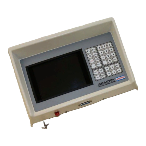
Figure 1: Sentry Control Panel showing Main Screen The figure above shows the Sentry Control Panel displaying the initial screen, seen when the unit is first turned on. The current time and date are displayed in the top right corner of the display screen. -
Page 9: Machine
If a machine appears to be missing, try the “PAGE UP” key. This may be necessary if the first machine in the list was previously offline. When the cursor is highlighting the desired machine, press the “ENTER” key to view the machine status screen. Sentry Control System 9... -
Page 10: Figure 4: Operation Summary
Alarms Displays the machine’s first six active alarms. The “CLEAR” key can be used to acknowledge alarms from this screen. See the ‘Alarm Screen’ section on Page 110 for more information. 10 Sentry Control System... -
Page 11: Change Setpoints
To select the ‘Change Setpoint’ function, use the “UP/DOWN” arrow keys. Pressing “ENTER” begins the process of changing the setpoint of a specific machine. Figure 6: Change Setpoints Sentry Control System 11... -
Page 12: Figure 7: Password Entry
When the cursor highlights the desired machine, press Figure 8: Machine List “ENTER” to change the selected machine’s setpoint, or “EXIT” to return to the machine menu. 12 Sentry Control System... -
Page 13: Figure 9: Abort Active Profile
RH and must fall within the humidity range listed above. Once all values are entered correctly, press “ENTER” to continue, or “EXIT” to abort. If the screen is aborted, the setpoints will remain unchanged. Sentry Control System 13... -
Page 14: Dry Out
After the specified time period has elapsed, dry out mode shuts off Figure 12: Dry Out Mode automatically and damper operation returns to normal. 14 Sentry Control System... -
Page 15: Figure 13: Password Entry
Figure 14: Machine List highlighted and the “ENTER” key is pressed, the operator will be asked for confirmation to toggle the current mode. Press “EXIT” to leave the modes unchanged and return to the ‘Machine’ menu. Sentry Control System 15... -
Page 16: Figure 15: Duration Of Dryout
Figure 16: Send Dryout Time above 90°F (32°C). With software version 1.23 and above, the operator may proceed even if the temperature is above 90°F (32°C). 16 Sentry Control System... -
Page 17: Profiles
“UP” and “DOWN” arrow keys and then pressing “ENTER” activates the selected function. Refer to the Network Edit Profile section on Page 77 to change profiles on more than one machine at a time. Figure 18: Edit Profiles Sentry Control System 17... -
Page 18: Figure 19: Password Entry
Figure 20: Machine List When the cursor is highlighting the desired machine, press “ENTER” to edit the profiles of the selected machine, or press “EXIT” to return to the profile submenu. 18 Sentry Control System... -
Page 19: Figure 21: Profile List
The “SELECT” key can be used to move the cursor line to the right hand column of setpoints and vice versa. With software version 1.20 and above, the “SELECT” key activates ‘JEAD’ mode when the cursor is highlighting the ‘Damper’ column. Sentry Control System 19... -
Page 20: Figure 23: Selecting Profiles To Store
The desired option can be selected using the “UP” and “DOWN” arrow keys to highlight the choice, and then Figure 24: Send Profile pressing “ENTER”. Pressing the “EXIT” key will have the same effect as selecting ‘Abort’. 20 Sentry Control System... -
Page 21: Start Profile
Figure 25: Start Profile If password security is enabled, the operator is requested to enter the password after selecting the desired group of machines. An incorrect password denies entrance to the ‘Start Profile’ function. Figure 26: Password Entry Sentry Control System 21... -
Page 22: Figure 27: Machine List
“ENTER”. Only ‘Valid’ profiles can be chosen; an error message is displayed if an ‘Unused’ slot is chosen. Figure 28: Select Profile to Start 22 Sentry Control System... -
Page 23: Figure 29: Profile Start Date
In standby mode the machine can run at a lower temperature than normally allowed, making it possible to use the machine as an egg room. The damper opening can be set anywhere from 0 to 100%. Sentry Control System 23... -
Page 24: Machine Setup
‘Alarm Setup’, ‘Alarm Ranges’, ‘Turn Setup’, ‘Humidity Control’, and ‘JM Fan’ and ‘JM Cool Setup’ (for hatcheries running JM Machines). Pressing “ENTER” brings up a list of the six submenus listed above. Figure 32: Machine Setup 24 Sentry Control System... -
Page 25: Alarm Setup
Figure 33: Alarm Setup If password security is enabled, the user is requested to enter a password after selecting the desired group of machines. An incorrect password denies entrance to the ‘Alarm Setup’ screen. Figure 34: Password Entry Sentry Control System 25... -
Page 26: Figure 35: Machine List
This field can also be programmed for a range of 0.0 to 25.5 minutes. Note: If it is programmed to be 0.0, this alarm cannot be acknowledged and therefore remains in the alarming state until the alarm condition is corrected. This field is edited in the same way as described above. 26 Sentry Control System... -
Page 27: Alarm Ranges
Under this menu, the operator can choose which group of machines are to be configured. Press “ENTER” when the desired selection is highlighted. Figure 38: Alarm Ranges Sentry Control System 27... -
Page 28: Figure 39: Password Entry
When the cursor is Figure 40: Machine List highlighting the desired machine, press “ENTER” to edit the Alarm Ranges for the selected machine, or press “EXIT” to abort the function. 28 Sentry Control System... -
Page 29: Figure 42: Send Alarm Range
‘Abort’ returns to the previous screen without altering the Alarm Range setup, and ‘Send Alarm Range’ sends the new values to the specified machine and activates the new Alarm Range values immediately. Figure 42: Send Alarm Range Sentry Control System 29... -
Page 30: Turn Setup
If password security is enabled, the user is requested to enter a password after selecting the desired group of machines. An incorrect password denies entrance to the ‘Turn Setup’ screen. Figure 44: Password Entry 30 Sentry Control System... -
Page 31: Figure 45: Machine Selection
“SELECT” key. Pressing Figure 46: Edit Egg Turn Setup “EXIT” will return to the previous submenu without making any changes to the Egg Turn Setup. For ‘JM Turn Setup’ refer to Appendix D on Page 120. Sentry Control System 31... -
Page 32: Humidity Control
14 day period. To edit the ‘Humidity Control’ features of a particular machine, press “ENTER” when ‘Humidity Control’ is highlighted. NOTE: The pan filling function Figure 48: Humidity Control requires the installation of an optional solenoid valve. 32 Sentry Control System... -
Page 33: Figure 49: Password Entry
When the cursor is Figure 50: Machine List highlighting the desired machine, press “ENTER” to edit the ‘Humidity Control’ for the selected machine, or press “EXIT” to abort the function. Sentry Control System 33... -
Page 34: Figure 51: Humidity Control Setup
‘Abort’ returns to the previous screen without altering the Humidity Control setup, and ‘Send Humidity Setup’ sends the new values to the specified machine and activates the new Humidity Control variables immediately. Figure 52: Send Humidity Control Setup 34 Sentry Control System... -
Page 35: Jm Fan Setup
The feature can be activated at any time from 0.0 to 50.0 days. Setting the value at zero disables the reverse blower and water cooling feature. Figure 54: Cooling Control Setup Sentry Control System 35... -
Page 36: Alarm Override
Select ‘Cancel Override’ to turn off the override before it has expired. To change the ‘Alarm Figure 56: Change Override Override’ on all machines of a given type, see the ‘Network Alarm Override’ section on Page 73. 36 Sentry Control System... -
Page 37: Figure 57: Password Entry
“HOME” and “END” keys move the cursor to the corresponding point in the machine list. When the desired machine is Figure 58: Machine List highlighted, press “ENTER” to change the alarm override, or “EXIT” to abort the function. Sentry Control System 37... -
Page 38: Figure 60: Alarm Override Option
“SELECT” to toggle the field between ‘Normal’ and ‘Override’. Once the appropriate alarms have been selected, press “ENTER” to continue, or “EXIT” to abort changes and return to the machine selection screen. Figure 60: Alarm Override Option 38 Sentry Control System... -
Page 39: Cancel Override
This function allows an active alarm override to be canceled before it expires on its own. To turn it back on after an override is canceled, the ‘Change Alarm Override’ function must be used. Figure 62: Cancel Override Sentry Control System 39... -
Page 40: Figure 63: Password Entry
Figure 64: Machine List press “SELECT” to change the alarm override state. An error message is displayed if the operator attempts to select a machine that does not have alarm override enabled. 40 Sentry Control System... -
Page 41: Calibration
The current offsets can also be viewed, to see if a sensor is substantially out of calibration. Figure 66: Calibration Sentry Control System 41... -
Page 42: View Offsets
“PAGE UP/DOWN” keys to see the next page of machines. Press “ENTER” to display the highlighted machine’s sensor offset, or “EXIT” to return to the ‘Calibration’ submenu. Figure 68: Machine List 42 Sentry Control System... -
Page 43: Change Calibration
Press “EXIT” to return to the machine selection screen. 3.7.2 Change Calibration This function is used to adjust a machine’s calibration parameters. Use the up and down arrow keys to select ‘Change Offsets’ and press “ENTER” to continue. Figure 70: Change Offsets Sentry Control System 43... -
Page 44: Figure 71: Password Entry
95, and then retry this operation. With version 1.22 or later, humidity can be calibrated in RH or wet bulb. Conversion errors may occur if the sensor reads RH and the machine is calibrated in wet bulb. 44 Sentry Control System... -
Page 45: Figure 73: Adjust Sensor Offset
NOTE: Since the offsets are stored in the machine controller, the sensors must be recalibrated if the machine controller’s processor board (PTA410) is replaced, or a Figure 74: Send Sensor Offsets different sensor module is connected to the machine. Sentry Control System 45... -
Page 46: Version
Highlight the desired machine using the “UP” and “DOWN” arrow keys, or “PAGE UP/ DOWN”, “HOME” and “END” to move around in the machine list. Press “ENTER” to view the software version. Figure 76: Machine List 46 Sentry Control System... -
Page 47: Reset Machine
“ENTER” to continue. NOTE: This function should be used with care and only when absolutely necessary, since the machine will take some time before the temperature control returns to normal after a reset. Figure 78: Reset Machine Sentry Control System 47... -
Page 48: Figure 79: Password Entry
Reset’ function. Figure 79: Password Entry Highlight the desired machine using either the arrow keys, the “PAGE UP/DOWN” keys, or the “HOME” and “END” keys. Press “ENTER” to continue to the next step. Figure 80: Machine List 48 Sentry Control System... -
Page 49: Figure 81: Send Machine Reset
“ENTER”. If the machine’s fans were turned on when resetting, they will turn off for a few seconds while the machine re-initializes. The machine may also create several alarms during Figure 81: Send Machine Reset reinitialization. Sentry Control System 49... -
Page 50: Reports
Choose the machine types for which reports are required by highlighting the choice using the up and down Figure 83: Machine Type arrow keys, and then pressing “ENTER”. Pressing “EXIT” will return to the ‘Reports’ menu. 50 Sentry Control System... -
Page 51: Printer Report
‘Screen Report’ produces, except the report is sent to an attached printer instead of the screen. Press “ENTER” for the machine type selection submenu. Figure 85: Printer Report Sentry Control System 51... -
Page 52: Figure 86: Machine Types
‘Stop Printing’ will cancel the report, but the display panel must still be able to communicate with the printer to finish up properly. In other words, the printer report is still active. Refer to the ‘Printer’ section on Page 99 for instructions on cancelling the report completely. 52 Sentry Control System... -
Page 53: Auto Report
Choosing ‘All’ will print a report for all machines. Choose the machine type by moving the cursor to the desired selection and pressing “ENTER”. Figure 89: Machine Type Sentry Control System 53... -
Page 54: Figure 90: Auto Report Details
If any of the fields contain invalid data, an error Figure 91: Auto Report Start Date message is displayed and the cursor is placed on the offending field. Press “EXIT” to return without making any changes. 54 Sentry Control System... -
Page 55: Figure 92: Auto Report Interval
After a display panel is powered on and auto reports are enabled, it will take 1 to 2 minutes before the first auto report is printed out. Sentry Control System 55... -
Page 56: Network
If password security is enabled, the operator is requested to enter the password. An incorrect password denies entrance to the ‘Select Status’ function. Figure 95: Password Entry 56 Sentry Control System... -
Page 57: Figure 96: Machine Status Select
‘Off’ to ‘Active’ or ‘Maint’ and vice versa. After changing the status, it may take a few seconds before the screen is updated to reflect the change. Figure 97: Send Status Change Sentry Control System 57... -
Page 58: Clock
Select the function and press “ENTER” to change the time. Press “EXIT” to return to previous menu. If the machine is running version 1.20 or newer, the clock functions are Figure 99: Set Time password protected. 58 Sentry Control System... -
Page 59: Figure 100: Password Entry
To enter the time exactly, type in a time that is a few seconds in the future. Press “ENTER” when all numbers are entered, or press “EXIT” to abort without changing the time. Figure 101: Time Entry Sentry Control System 59... -
Page 60: Set Date
‘day in cycle’ corresponding to this new date. Select the function and press “ENTER” to change the date. Press “EXIT” to return to the previous menu. Figure 103: Set Date 60 Sentry Control System... -
Page 61: Figure 104: Password Entry
1 must be entered as ‘01’. The new date will not take effect until the next step is completed. Press “ENTER” when all numbers are entered, or press “EXIT” to abort without changing the date. Figure 105: Date Entry Sentry Control System 61... -
Page 62: Network Machine Setup
‘Alarm Setup’, ‘Alarm Ranges’, ‘Turn Setup’, ‘Humidity Control’, and ‘JM Fan’ and JM Cool Setup’ Figure 107: Machine Setup (for hatcheries running JM Machines). Pressing “ENTER” brings up a list of the six submenus listed above. 62 Sentry Control System... -
Page 63: Network Alarm Setup
An error message will be shown informing that no machines of that type were found on the network if such a machine type is selected. Figure 109: Machine Type Sentry Control System 63... -
Page 64: Figure 110: Password Entry
When the cursor is highlighting the desired machine, press Figure 111: Machine List “ENTER” to view the alarm setup for the selected machine, or press “EXIT’ to abort the function. 64 Sentry Control System... -
Page 65: Figure 112: Alarm Setup Editing
‘’DOWN” arrow keys to make a choice and press “ENTER” to continue, or “EXIT” to abort. If ‘Specific Machine’ is chosen go to the next step, or skip to the screen shown in Figure 115. Figure 113: Machine Type Sentry Control System 65... -
Page 66: Figure 114: Machine Selection
‘Machine’ menu, except that this function changes the alarm setup of all machines of a given machine type. Refer to the ‘Alarm Setup’ section on Page 25 to change the alarm parameters of a single machine. 66 Sentry Control System... -
Page 67: Network Alarm Ranges
Figure 116: Alarm Ranges If password security is enabled, the user is requested to enter a password after selecting the desired group of machines. An incorrect password denies entrance to the Network ‘Alarm Ranges’ screen. Figure 117: Password Entry Sentry Control System 67... -
Page 68: Figure 118: Alarm Range Setup
Alarm Range setup, and ‘Send Alarm Range’ sends the new values to all machines of a specific type connected to the network and activates the new Alarm Range values immediately. Figure 119: Send Alarm Ranges 68 Sentry Control System... -
Page 69: Network Turn Setup
Setup’ section on Page 300. If password security is enabled, the user is requested to enter a password after selecting the desired group of machines. An incorrect password denies entrance to the Network ‘Turn Setup’ screen. Figure 121: Password Entry Sentry Control System 69... -
Page 70: Figure 122: Edit Egg Turn Setup
‘Send Turn Setup’ sends the new values to all machines of a specific type connected to the network and activates the new egg turn variables immediately. Figure 123: Send Turn Setup 70 Sentry Control System... -
Page 71: Network Humidity Control
Control’ is highlighted. If password security is enabled, the user is requested to enter a password after selecting the desired group of machines. An incorrect password denies entrance to the Network ‘Humidity Control’ screen. Figure 125: Password Entry Sentry Control System 71... -
Page 72: Figure 126: Edit Humidity Control Setup
Humidity Control setup, and ‘Send Humidity Setup’ sends the new values to all machines of a specific type and activates the new Humidity Control variables immediately. Figure 127: Send Humidity Control Setup 72 Sentry Control System... -
Page 73: Network Alarm Override
Refer to the ‘Alarm Override’ section on page 36 for information on changing the parameters of a single machine. Figure 128: Alarm Override This submenu shows the two options available under the ‘Alarm Override’ menu. Figure 129: Alarm Override submenu Sentry Control System 73... -
Page 74: Figure 130: Machine Type
Figure 130: Machine Type If password security is enabled, the operator is requested to enter the password. An incorrect password denies entrance to the ‘Alarm Override’ screen. Figure 131: Password Entry 74 Sentry Control System... -
Page 75: Figure 132: Override Duration
“SELECT” to toggle the field between ‘Normal’ and ‘override’. Once the appropriate alarms have been selected, press “ENTER” to continue, or “EXIT” to abort changes and return to the submenu listing the different machine types. Figure 133: Alarm Override Editing Sentry Control System 75... -
Page 76: Network Profiles
The copy functions are useful to reprogram a machine after its processor circuit board (PTA410) has been replaced at a machine controller. Figure 135: Profiles 76 Sentry Control System... -
Page 77: Network Edit Profiles
Figure 136: Edit Profiles If password security is enabled, the operator is requested to enter the password. An incorrect password denies entrance to the ‘Edit Profiles’ function. Figure 137: Password Entry Sentry Control System 77... -
Page 78: Figure 138: Machine List
With software version 1.20 Figure 139: Profile List and above, use the “CLEAR” key to erase the currently selected profile. If this profile is active, it will not be erased. 78 Sentry Control System... -
Page 79: Figure 140: Edit Profile
Once all chosen slots have been selected, press “ENTER” to select which machines are to receive the Figure 141: Store Profile profile. Press “EXIT” to return to the edit screen without storing changes at the machine. Sentry Control System 79... -
Page 80: Figure 142: Machine Type
Press “ENTER” to continue to the next step, or “EXIT” to abort and return to the profile editing screen. Figure 143: Select Specific Machine 80 Sentry Control System... -
Page 81: Network Copy Profile
‘Copy Profile’ is essentially the same as ‘Edit Profile’, except that it lacks the step where the profile can be edited. Figure 145: Copy Profile Sentry Control System 81... -
Page 82: Figure 146: Password Entry
Highlight the desired machine using the arrow keys, and the “PAGE UP/DOWN” keys to display machines not shown, and press “ENTER” to continue, or “EXIT” to abort without making changes. Figure 147: Machines List 82 Sentry Control System... -
Page 83: Figure 148: Profile List
This feature provides a quick way to build up profiles that have small differences. Once all slots have been selected, press “ENTER” to continue, or “EXIT” to abort the copy Figure 149: Store Profiles process. Sentry Control System 83... -
Page 84: Figure 151: Select Specific Machine
Press “ENTER” to continue to the next step, or “EXIT” to abort and return to the profile selection screen. Figure 151: Select Specific Machine 84 Sentry Control System... -
Page 85: Network Copy All Profiles
Only ‘Valid’ profiles will be transferred. This function is most useful to reprogram a machine after its processor board (PTA410) has been replaced. Figure 153: Copy All Profiles Sentry Control System 85... -
Page 86: Figure 154: Password Entry
Highlight the desired machine using the arrow keys, and the “PAGE UP/DOWN” keys to display machines not shown, and press “ENTER” to continue, or “EXIT” to abort without making changes. Figure 155: Machine List 86 Sentry Control System... -
Page 87: Figure 156: Machine Type
Press “ENTER” to continue to the next step, or “EXIT” to abort and return to the source machine selection screen. Figure 157: Select Specific Machine Sentry Control System 87... -
Page 88: Configure Network
Figure 159: Configure Network added or removed from the network, if a display panel has lost its configuration, or if a software update is made on any machine (i.e. a newer version number). 88 Sentry Control System... -
Page 89: Figure 160: Password Entry
Correct communication errors before proceeding (there may be a network error). If a machine needs to be powered off, use the ‘Select Status’ function described in section 6.1 on page 56 to place the machine offline, to disable the resulting communication alarm. Sentry Control System 89... -
Page 90: Figure 162: Manual Configuration
NOTE: If the master display resets during configuration (indicated by a short beep and the display changing back to the main screen), then a fiber optic connector may be exposed to light. Correct the problem before re-executing this function. 90 Sentry Control System... -
Page 91: Change Password
Figure 164: Password Change The ‘Password Security Level’ option allows the operator to set the access level for various users and functions requiring password access (see section 5.7.1 on page 93). Figure 165: Change Password Submenu Sentry Control System 91... -
Page 92: Figure 166: Current Password Entry
Press “EXIT” to abort without changing the password. NOTE: Do not forget this new password, as it will be impossible to change the password again without knowing the old password. Figure 167: New Password Entry 92 Sentry Control System... -
Page 93: Enhanced Password Security
If the user is setting level 1 password and there is no level 2 password, level 2 password will become the same password. If the level 2 password is disabled, then the level 1 password will also be disabled. Sentry Control System 93... -
Page 94: Display
(see Section 6.2 on following page), this units selection will also apply to the humidity readings. Move the cursor to desired preference and press “ENTER”, or “EXIT” to leave the preference unchanged. Figure 170: Temperature Units 94 Sentry Control System... -
Page 95: Humidity
Also there could be a high humidity alarm even though the actual wet bulb temperature is less than the setpoint, because in fact the relative actual is higher. It is recommended to use relative humidity for units of display. Sentry Control System 95... -
Page 96: Language
‘’ENTER’’ to use the new selection. If a different language is selected, the menus will be redrawn using the new language. Press “EXIT” to leave the current language preference unchanged. Figure 174: Language Selection 96 Sentry Control System... -
Page 97: Alarm Light
‘Enable Alarm Light’ or to stay off by selecting ‘Disable Alarm Light’. Highlight desired option and press “ENTER” or “EXIT” to leave the option unchanged. Figure 176: Disable/Enable Alarm Sentry Control System 97... -
Page 98: Audible Alarm
‘Enable Audible Alarm’ or to stay off by selecting ‘Disable Audible Alarm’. Highlight desired option and press “ENTER” or “EXIT” to leave the option unchanged. Figure 178: Disable/Enable Audible Alarm 98 Sentry Control System... -
Page 99: Printer
NOTE: If the printer only prints random characters after pressing the “PRINT SCREEN” key, then most likely an incorrect printer driver is being used. Refer to Section 6.ó.3 on Page 102 to change the printer type. Figure 180: Printer Status Sentry Control System 99... -
Page 100: Cancel Printing
6.6.2 Cancel Printing The ‘Cancel Printing’ function is used to stop a print job which is currently active. If no print job is active an error message is displayed. Figure 182: Cancel Printing 100 Sentry Control System... -
Page 101: Figure 183: Send Stop Printing
Printing on the Sentry System: The display panel has the capability to send data to the printer while the operator uses the display for other functions, this is called background printing. While printing is in progress the operator may freely move around in the menu structure and invoke any function, but no other print job can be started, an error message will be shown if this happens. -
Page 102: Select Printer
When using the “PRINT SCREEN” function this will produce a larger size screen dump which will be printed sideways. With software version 1.20 and above, the ‘HP Ink Jet’ also works with HP or compatible laser printers. 102 Sentry Control System... -
Page 103: Figure 186: Bar Graph
If no bars are Figure 187: View Bar Graph visible for a machine, then the lower bounds need to be reduced in the scaling dialog box or by enabling display of bars. See next step. Sentry Control System 103... -
Page 104: Figure 188: Graph Scaling
Sample Time’ function described in Section 7.3, which determines how many days of data is shown on the graph. A cursor is provided to inspect the actual value of any graph point. Figure 189: Line Graph 104 Sentry Control System... -
Page 105: Figure 190: Machine List
If a machine has been powered down for a extended period of time, the graph will be blank for that time period. Sentry Control System 105... -
Page 106: Figure 192: Graph Scaling
This selection will determine how many days of data are displayed by the line graph function. Press “ENTER” to continue. Figure 193: Line Sample Scaling 106 Sentry Control System... -
Page 107: Figure 194: Password Entry
“ENTER” to continue. If ‘Specific Machine’ is selected, the screen shown in the next step is shown, otherwise the selection box of Figure 196 will be shown. Figure 195: Machine Type Sentry Control System 107... -
Page 108: Figure 196: Select Specific Machine
NOTES: a) After changing the sample time, there will be no indication on the line graph that it was changed, the machine will just add points at a different rate. b) When the dialog box is first displayed, the cursor does not indicate what the current sampling time is. 108 Sentry Control System... -
Page 109: Figure 198: Send Sample Time
Choose ‘Send Sample Time’ using the arrow keys and press “ENTER” to send the new selection. The line graph sampling time of the selected machine(s) will be set to the new setting. Figure 198: Send Sample Time Sentry Control System 109... -
Page 110: Figure 199: Alarm Screen
NOTE: Only an alarm in Figure 200: Alarm Times Screen inverse text will have an end time, and an active alarm could have been acknowledged but has since returned to the active state. 110 Sentry Control System... - Page 111 The following is a list and description of all the alarms that can occur on the Sentry system: High Temperature: This alarm indicates that the actual temperature reading has climbed above the temperature setpoint by 0.4 °F (0.222 °C) or more.
- Page 112 Alarm Bypass: This is an informational alarm indicating that the alarm bypass is activated, serving mostly as a reminder to the operator. NOVRAM/RTC Failure: This alarm indicates that either the NOVRAM (which backs up important 112 Sentry Control System...
- Page 113 NOTE: Changing the board or one of the chips will require that the sensor be recalibrated, profiles and alarm setup to be reentered or copied from another machine. It is normal to get this alarm after a new processor board is installed. Sentry Control System 113...
- Page 114 Appendix A: Parts List The following is a list of the common replacement parts that may be ordered for the Sentry Control System through Jamesway: ACI spare parts kit (1-4 machines) ....................FB5732 ACI power interface module board ....................PTA417S Incubator power interface module board ..................
- Page 115 The display has a built in screen sever feature it is not used for a while. which is activated when there is no keypad activity for 15 minutes. Simply press any key to restore the screen. Sentry Control System 115...
- Page 116 During Network Configuration, one or more on the machines. Check the address settings on machines are missing from the system. the PTA410 board (if two machines have been assigned the same address, neither will show up on the system). 116 Sentry Control System...
- Page 117 “ALARM” key. memory to execute the selected function. This is usually caused by using the ‘Print Screen’ function when no printer is attached. Turn the display panel off for a few seconds, then turn it back on. Sentry Control System 117...
-
Page 118: Figure 201: Pta410 Machine Controller Switch Settings
Appendix C: Address Setting Each unit on the network must have a unique address. On the Sentry system an address is constructed from the room number, unit type and unit number. All three switch groups must be set for proper unit identification. -
Page 119: Figure 201: Pta410 Machine Controller Switch Settings
Unit #32 12345678 Open NOTE: When changing circuit boards, make sure that all DIP switches are set to match the old board, or the network may have communication alarms. Figure 201: PTA410 Machine Controller Switch Settings Sentry Control System 119... -
Page 120: Figure 202: Pta410 Machine Controller Switch Settings For Jm Machines
Blower on at 0.4˚C Water cooling on at 0.2˚C JM Hatcher Fan does not referse Options Room Number Unit Type 1234 12345678 1234 Open Open Open Figure 202: PTA410 Machine Controller Switch Settings for JM Machines 120 Sentry Control System... - Page 121 Open NOTE: When changing circuit boards, make sure that all DIP switches are set to match the old board, or the network may have communication alarms. Figure 202: PTA410 Machine Controller Switch Settings for JM Machines Sentry Control System 121...
-
Page 122: Figure 203: Jm Egg Turn Setup
ENTER. Note: If all racks are inside the machine and all are sensed, then the dialog box will not be shown and the operator will not be asked to confirm rack setup. 122 Sentry Control System... - Page 123 This is also why there is no alarm when the racks are leveled. The machine state screen will say Racks detected: 0, but if the racks are placed back in the machine before 2 turn cycles have taken place, there will not be an alarm. Sentry Control System 123...
- Page 124 Glossary ACI: Advanced Concept Incubation. This refers to Jamesway’s single-stage incubation equipment. Display Panel: A display panel allows the operator to view or change parameters of any machine connected to the network. Once a parameter has been changed, it is updated on all display panels. A machine can carry on without any intervention from the display panel.
- Page 125 List of Figures Figure 1: Sentry Control Panel showing Main Screen ............ 8 Figure 2: Machine State ....................9 Figure 3: Machine List ...................... 9 Figure 4: Operation Summary ..................10 Figure 5: View Profile ...................... 11 Figure 6: Change Setpoints ..................... 11 Figure 7: Password Entry ....................
- Page 126 Figure 96: Machine Status Select ................... 57 Figure 97: Send Status Change ..................57 Figure 98: Network Clock ....................58 Figure 99: Set Time ......................58 Figure 100: Password Entry ................... 59 Figure 101: Time Entry ....................59 126 Sentry Control System...
- Page 127 Figure 148: Profile List ....................83 Figure 149: Store Profiles ....................83 Figure 151: Select Specific Machine ................84 Figure 150: Machine Type ....................84 Figure 152: Send Copy Profile ..................85 Figure 153: Copy All Profiles ..................85 Sentry Control System 127...
- Page 128 Figure 201: PTA410 Machine Controller Switch Settings ........... 118 Figure 201: PTA410 Machine Controller Switch Settings ........... 119 Figure 202: PTA410 Machine Controller Switch Settings for JM Machines ..... 121 Figure 203: JM Egg Turn Setup ................... 122 128 Sentry Control System...
- Page 129 JM Fan Setup ........35 Temperature ........94 Troubleshooting ......115 Language .......... 96 Turn Setup ........30 Line Graph ........104 Turn Setup on JM Incubators ..122 Line Sample Time ......106 Version ..........46 View Offsets ........42 Sentry Control System 129...
Need help?
Do you have a question about the Sentry and is the answer not in the manual?
Questions and answers