
Related Manuals for YASKAWA Sigma Mini SGMM Series


Summary of Contents for YASKAWA Sigma Mini SGMM Series
- Page 1 (217) 352-9330 | Click HERE Find the Yaskawa SGMM-A1S312 at our website:...
- Page 2 YASKAWA AC Servomotors and Driver SGMM Servomotor SGDF Servopack YASKAWA MANUAL NO. SIE-S800-27C Artisan Technology Group - Quality Instrumentation ... Guaranteed | (888) 88-SOURCE | www.artisantg.com...
- Page 3 Safety Information The following conventions are used to indicate precautions in this manual. Failure to heed precautions pro- vided in this manual may result in serious or possibly even fatal injury or damage to the products or to re- lated equipment and systems. WARNING Indicates precautions that, if not heeded, could result in loss of life or serious injury.
- Page 4 Visual Aids The following aids are used to indicate certain types of information for easier reference. Indicates references for additional information. Indicates definitions of difficult terms that have not been previously explained in TERMS this manual. Indicates information that is applicable only to Servopacks for speed/torque con- trol (Model SGDF-jjCS).
-
Page 5: Table Of Contents
CONTENTS Safety Precautions ........... CHAPTER 1 BASIC OPERATION . - Page 6 CONTENTS 2.5.3 Gain Adjustment ..........2-47 2.5.4 Offset Adjustment...
- Page 7 CONTENTS 4.1.2 Selecting a Servopack ..........Servomotor Ratings and Characteristics .
- Page 8 CONTENTS 6.1.3 EMC Directive ........... 6.1.4 TÜV Certification Body Authorized by EU .
- Page 9 Overview About this Manual This manual provides the following information for users of Σ-Series Servomotors and Servo Drives. • An overview of Servo Systems for first-time users. • Checking the product on delivery and basic applications of the Servo. • Servo applications. •...
- Page 10 BASIC USES OF Σ-SERIES PRODUCTS Basic Terms Meaning of Basic Terms Unless otherwise specified, the following definitions are used in this manual. Servomotor: Σ-Series SGMM Servomotor. Servopack: Σ-Series SGDF Servopack. Servo Drive: A set including an SGMM/SGDF Servomotor and an SGDF Servopack Servo System: A complete Servo control system consisting of Servo Drive, host controller, and peripheral devices.
-
Page 11: Safety Precautions
Safety Precautions The following precautions are for checking products upon delivery, installation, wiring, operation, maintenance and inspections. J Checking Products upon Delivery CAUTION D Always use the Servomotor and Servopack in one of the specified combinations. Not doing so may cause fire or malfunction. J Installation CAUTION D Never use the products in an environment subject to water, corrosive gases, inflammable gases,... - Page 12 BASIC USES OF Σ-SERIES PRODUCTS J Operation WARNING D Never touch any rotating motor parts while the motor is running. Doing so may result in injury. CAUTION D Conduct trial operation on the Servomotor alone with the motor shaft disconnected from machine to avoid any unexpected accidents.
- Page 13 The edition number appears on the front and back covers. S If the manual must be ordered due to loss or damage, inform your nearest Yaskawa representa- tive or one of the offices listed on the back of this manual.
- Page 14 Yaskawa. No patent liability is assumed with respect to the use of the information contained herein. Moreover, because Yaskawa is constantly striving to improve its high-quality products, the information contained in this manual is subject to change without notice.
-
Page 15: Chapter 1 Basic Operation
BASIC OPERATION This chapter describes the initial procedures when Σ-Series products are de- livered. It also explains the basic methods of connecting and operating Σ-Se- ries products. Both first-time and experienced servo users must read this chapter. 1.1 Precautions ....... 1.2 Installation . -
Page 16: Precautions
BASIC OPERATION Precautions This section provides precautions that must be observed when using Σ-Series products. Do not connect the Servomotor directly to a commercial power supply. Do not plug the Servomotor directly into the com- Do not connect directly. mercial power supply. Direct connection to the commercial power supply will damage the Servo- motor. - Page 17 1.1Precautions Perform noise reduction and grounding properly. If the signal line is noisy, vibration or malfunction Casing will result. Servopack Signal Servomotor line Install the system according to the following pre- cautions. D Separate high-voltage cables from low-voltage cables. D Use cables as short as possible. Be sure to ground D Be sure to ground (ground resistance 100 Ω...
-
Page 18: Installation
Check for looseness by using a screwdriver. If any of the above items are faulty or incorrect, contact the dealer from which you pur- chased the products or your Yaskawa representative. — 1-4 — Artisan Technology Group - Quality Instrumentation ... Guaranteed | (888) 88-SOURCE | www.artisantg.com... - Page 19 1.2Installation Appearance Nameplate Type Standard Servomotors Σ-Series SGMM Servomotor Rated output A1: 10 W B3: 3 W A2: 20 W B5: 5 W A3: 30 W B9: 10 W Supply voltage B: 100 VAC C: 24 VDC S: EC safety standards, 24 VDC (10 W, 20 W) Encoder specifications 3: 2048 P/R incremental encoder...
-
Page 20: Installing The Servomotor
BASIC OPERATION 1.2.2 Installing the Servomotor 1.2.2 Installing the Servomotor Servomotors can be installed either horizontally or vertically. If, however, the Servomotor is installed incorrectly or in an inappropriate location, the service life will be shortened or unex- pected problems will occur. To prevent this, always follow the installation instructions de- scribed below and install properly. - Page 21 1.2Installation Alignment Align the shaft of the Servomotor with that of the equipment to be controlled, then connect the shafts with couplings. Install the Servomotor so that alignment accuracy falls within the range shown in the following diagram. Measure this distance at four different positions in the circumference. The difference between the maximum and minimum measurements must be 0.03 mm or less.
- Page 22 BASIC OPERATION 1.2.2 Installing the Servomotorcont. Allowable Load on Shaft End Mechanical shock to the shaft end must be less than 490 m/s and must be applied no more than twice. Design the mechanical system so that thrust load and radial load applied to the Servo- motor shaft end during operation falls within the range shown in the following table.
-
Page 23: Installing The Servopack
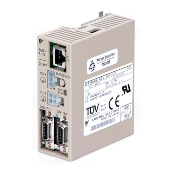
1.2Installation 1.2.3 Installing the Servopack The SGDF Servopack is a book-shaped compact ser- vo controller. Incorrect installation will cause malfunctions. Always SGDF- A1CS observe the following precautions when installing the DC24V SERVOPACK Servopack. Storage: CN2/PG CN1/IO When the Servopack is to be stored with the pow- er cable disconnected, store it within the following temperature range: SGDF Servopack... - Page 24 BASIC OPERATION 1.2.3 Installing the Servopackcont. Installation Method When installing multiple Servopacks side by side in a control panel, observe the following installation method. 50 mm or more 30 mm 10 mm 50 mm or more or more or more Servopack Orientation Install Servopack perpendicular to the wall so that the front panel faces outward.
- Page 25 1.2Installation 1.2.4 Power Loss The amount of power lost by Servopacks at the rated output is shown in the following table. Servopack Type Capacity (W) Inrush Current Output Current Power Loss (W) (Aop) (A rms) SGDF-A1C SGDF-A2C SGDF-A3C SGDF-B3C SGDF-B5C SGDF-B9C —...
-
Page 26: Connection And Wiring
BASIC OPERATION 1.3.1 Connecting to Peripheral Devices Connection and Wiring This section describes how to connect Σ-Series products to peripheral devices and explains a typical example of wiring the main circuit. It also describes an example of connecting to main host controllers. 1.3.1 Connecting to Peripheral Devices This section shows a standard example of connecting Σ-Series products to peripheral de- vices and briefly explains which peripheral devices can be connected and in which locations... - Page 27 1.3Connection and Wiring Host Connect the SGDP SERVOPACK to a Yaskawa host controller. Controller MP910, MP920, Power supply: MP930, and MP−SG1 with a Motion Module Molded-case circuit Single-phase breaker (MCCB) 200 or 100 VAC Used to protect Digital Operator power supply line.
-
Page 28: Main Circuit Wiring And Power On Sequence
BASIC OPERATION 1.3.2 Main Circuit Wiring and Power ON Sequence 1.3.2 Main Circuit Wiring and Power ON Sequence This section shows a typical example of wiring the main circuit for Σ-Series Servo, and de- scribes the main circuit terminal functions and power ON sequence. Typical Wiring Example Single-phase 100 VAC (50/60 Hz) - Page 29 1.3Connection and Wiring Designing the Power ON Sequence Observe the following precautions when designing the power ON sequence. • Design a power ON sequence so that the power is turned OFF when a servo alarm signal is output. (See the previous circuit diagram.) •...
-
Page 30: Examples Of Connecting Host Controllers
Note This section describes signals related to the Servopack only. For other signals, refer to the relevant technical documentation. Example of Connecting to PROGIC-8 Servopack for Speed/Torque Control Speed/Torque Servopack 24VDC Yaskawa PROGIC-8 /PAO /PBO /PCO V-REF (T-REF) +24OUT +24VIN... - Page 31 1.3Connection and Wiring Example of Connecting to GL-series B2833 Positioning Module Servopack for Speed/Torque Control Servopack Servomotor Speed/Torque Yaskawa DC24V +24 V JAMSC-B2833 SERVO NORMAL DECEL LS D/A OUTPUT V-REF (T-REF) START +24 V 0 STOP +24VIN /S-ON /PAO +12V /PBO −12V...
- Page 32 BASIC OPERATION 1.3.3 Examples of Connecting Host Controllerscont. Example of Connecting to GL-series B2813 Positioning Module Servopack for Position Control Positions Servopack Servomotor DC24V +24 V Yaskawa JAMSC-B2833 PULSE PULSE /PULSE /PULSE SERVO SIGN SIGN NORMAL /SIGN /SIGN 1kΩ +12 V...
- Page 33 Use the ALM signal to operate the alarm detection relay (Relay 1Ry) and turn OFF the power supply to the Servopack. : Twisted-pair cable Note Only signals for the OMRON C500-NC221 Position Control Unit and the Yaskawa Servopack are shown here. — 1-19 —...
- Page 34 Use the ALM signal to operate the alarm detection relay (Relay 1Ry) and turn OFF the power supply to the Servopack. Note Only signals for the OMRON C500-NC112 Position Control Unit and the Yaskawa Servopack are shown here. — 1-20 —...
- Page 35 *2 These pin numbers are the same for both X and Y axes. : Twisted-pair cable Note Only signals for the MITSUBISHI AD72 Positioning Unit and the Yaskawa Servopack are shown here. — 1-21 — Artisan Technology Group - Quality Instrumentation ... Guaranteed | (888) 88-SOURCE | www.artisantg.com...
- Page 36 Use the ALM signal to operate the alarm detection relay (Relay 1Ry) and turn OFF the power supply to the Servopack. Note Only signals for the MITSUBISHI AD75 Positioning Unit and the Yaskawa Servopack are shown here. — 1-22 —...
-
Page 37: Conducting A Test Run
1.4Conducting a Test Run Conducting a Test Run This section describes how to conduct a test run in two steps. The test run is divided into two steps. Complete a test run in step 1 first, then proceed to step 2. 1.4.1 Test Run in Two Steps Conduct the test run when wiring is complete. -
Page 38: Step 1: Test Run For Servomotor Without Load
BASIC OPERATION 1.4.2 Step 1: Test Run for Servomotor without Load 1.4.2 Step 1: Test Run for Servomotor without Load Check that the Servomotor is wired correctly. If the motor fails to rotate properly during a Ser- vo Drive test run, the cause is usually incorrect wiring. Conduct a test run for the motor without a load according to the procedure described below. - Page 39 1.4Conducting a Test Run Check input signals. Example of Internal status bit display Un-05 (Un-05, Un-06) Using the Digital Operator, check the input signal wir- ing in monitor mode. For the checking method, refer to 3.1.6 Operation in Monitor Mode. Turn each connected signal line ON and OFF to check /S-ON /P-CON...
- Page 40 BASIC OPERATION 1.4.2 Step 1: Test Run for Servomotor without Loadcont. Servopack for Speed/Torque Control This section describes the standard speed control Servopack Speed/Torque Servomotor setting. CN1-12 (1) Gradually increase the speed reference input CN1-13 (V-REF, CN1-12) voltage. The Servomotor will Servomotor rotates at a speed rotate.
- Page 41 1.4Conducting a Test Run Servopack for Position Control (1) Set parameter Cn-02 so that the reference pulse form matches the host controller out- put form. Refer to 2.2.2 Position References for details on how to select reference Positions pulse forms.) Selecting reference pulse form Bit 3 Bit 4...
-
Page 42: Step 2: Test Run With The Servomotor Connected To The Machine
BASIC OPERATION 1.4.3 Step 2: Test Run with the Servomotor Connected to the Machine 1.4.3 Step 2: Test Run with the Servomotor Connected to the Machine Note Before proceeding to step 2, repeat step 1 (conducting a test run for the Servomotor without load) until you are fully satisfied that the test has been completed successfully. -
Page 43: Supplementary Information On Test Run
1.4Conducting a Test Run 1.4.4 Supplementary Information on Test Run In the following cases, always refer to the information described below before starting a test run: • When using a Servomotor with a brake • When performing position control from the host controller Using a Servomotor with Brake A Servomotor with a brake is used for vertical axes or axes subject to external force. -
Page 44: Minimum Parameters And Input Signals
BASIC OPERATION 1.4.5 Minimum Parameters and Input Signals Reference Check from Host Check Method Review Items Items Controller Check the Servomotor speed as fol- lows: D Use the speed monitor (Un-00) of Jogging the Digital Operator. Check whether the (constant- Motor speed reference gain speed refer-... - Page 45 1.4Conducting a Test Run Changing Servomotor Rotation Direction If the specified direction of rotation differs from the actual direction of rotation, the wir- ing may be incorrect. In this case, recheck the wiring and correct it accordingly. If the direction of rotation is to be reversed, recheck the wiring and set the following param- eter: Cn-02 (bit 0) Reverse rotation mode...
-
Page 46: Chapter 2 Applications
APPLICATIONS This chapter is prepared for readers who have mastered the basic operating procedures and wish to learn more about the applications. It explains how to set parameters for each purpose and how to use each function. Read the appli- cable sections according to your requirements. - Page 47 2.5 Running the Motor Smoothly ....2-46 2.5.1 Soft Start Function ........2-46 2.5.2 Smoothing .
- Page 48 Before Reading this Chapter This chapter describes how to use each CN1 connector I/O signal for the Servopack and how to set the corresponding parameter. Refer to the following chapters for further information on areas covered in this chapter. • For a list of I/O signals, refer to Appendix B List of I/O Signals. •...
-
Page 49: Setting Parameters According To Machine Characteristics
APPLICATIONS 2.1.1 Changing Motor Rotation Direction Setting Parameters According to Machine Characteristics This section describes how to set parameters according to the dimensions and performance of the machine to be used. 2.1.1 Changing Motor Rotation Direction The Servopack provides a reverse rotation mode in which the direction of Servomotor rota- tion can be reversed without altering the Servomotor wiring. - Page 50 2.1Setting Parameters According to Machine Characteristics 2.1.2 Torque Limit The Servopack can provide the following torque control. • Level 1: To restrict the maximum output torque to protect the machine or workpiece (internal torque limit) • Level 2: To restrict torque after the motor moves the machine to a specified position (exter- nal torque limit) •...
- Page 51 APPLICATIONS 2.1.2 Torque Limitcont. Using /CLT Signal This section describes how to use contact output signal OUT2 as a torque limit output signal. I/O power supply Servopack + 24 V Photocoupler output Maximum operating voltage CN1-8 /CLT per output: 30 VDC Maximum output current per CN1-3 SG-COM...
- Page 52 2.1Setting Parameters According to Machine Characteristics Output Signal for Torque Restriction Function The torque restriction function /CLT • outputs the signal shown on Status indication mode bit data • the right. Monitor mode Un-05 bit 4 • Parameter Setting: Cn-2C = 4 Examples of Use: D Forced stopping D Holding workpiece by robot...
- Page 53 APPLICATIONS 2.1.2 Torque Limit cont. ON: CN1-*1 is at Torque is restricted. Limit value: low level. Cn-18 OFF: CN1-*1 is at Torque is not restricted. Normal operation status. high level. Note This function is changed to another function depending on the setting of parame- ter Cn-2C.
-
Page 54: Setting Parameters According To Host Controller
2.2Setting Parameters According to Host Controller Setting Parameters According to Host Controller This section describes how to connect a Σ-Series Servo to a host controller and how to set parameters. 2.2.1 Speed References Input a speed reference by using the following input signal “speed reference input.” Since this signal can be used in different ways, set the optimum reference input for the system to be created. - Page 55 APPLICATIONS 2.2.1 Speed References cont. Parameter Cn-03 can be used to change the voltage input range. Example of Input Circuit Servopack 470 Ω, 1/2 W or more The adjacent diagram shows an example of an input V-REF circuit. + 12 V 2 kΩ...
- Page 56 2.2Setting Parameters According to Host Controller Cn-01 Setting Control Mode Control Mode Bit B Bit A Speed Control Servopack This is normal speed control. Speed reference (CN1-12) D Speed reference is input from V-REF. P/PI changeover /P-CON (CN1-*1) D /P-CON signal is used to switch between P control and PI control.
- Page 57 APPLICATIONS 2.2.1 Speed References cont. Using /P-CON Signal: Proportional Control, etc. For Speed/Torque → Input /P-CON CN1-*1 Control and Position Control The function of input signal /P-CON changes with the memory switch setting. Servopack Switching between P control and PI control /P-CON Switching between zero-clamp enabled mode and zero-clamp disabled mode...
- Page 58 2.2Setting Parameters According to Host Controller 2.2.2 Position References Input a position reference by using the following input signal “reference pulse input.” Since there are several specifications for input signal, select reference input for the system to be created. Positions Pulse Input Reference Inputs a move reference by pulse input.
- Page 59 APPLICATIONS 2.2.2 Position References cont. Note The signal logic for open collector output is as follows. When Tr1 is ON Equivalent to high level input When Tr1 is OFF Equivalent to low level input Selecting Reference Pulse Form Use the following memory switches to select the reference pulse form to be used: →...
- Page 60 2.2Setting Parameters According to Host Controller Input Input Refer- Refer- Cn-02 Pulse Pulse ence ence Motor Forward Run Motor Forward Run Motor Reverse Run Motor Reverse Run Reference Reference Reference Reference Multipli- Multipli- Pulse Pulse Bit D Form Form Sign + pulse train Two-...
- Page 61 APPLICATIONS 2.2.2 Position References cont. (2) The error counter clear (CLR) signal must be ON for at least 20 μs. Otherwise, it be- comes invalid. Allowable Voltage Level and Timing for Reference Pulse Input Reference Pulse Form Electrical Specifications Remarks Sign + pulse train input The signs for each (SIGN + PULS signal)
-
Page 62: Encoder Output
2.2Setting Parameters According to Host Controller Use this signal to clear the error counter from the host controller. Bit A of memory switch Cn-02 can be set so that the error counter is cleared only once when the leading edge of an input pulse rises. Error Counter Clear Signal Factory For Position Control... - Page 63 APPLICATIONS 2.2.3 Encoder Output cont. Speed/Torque Control The output circuit is for line driver output. Connect each signal line according to the following circuit diagram. Servopack Host controller Line receiver CN1-14 Phase A Phase CN1-15 /PAO CN1-16 Phase B Phase CN1-17 /PBO Phase C...
- Page 64 2.2Setting Parameters According to Host Controller Position Control The output circuit is for open-collector outputs. Connect each signal line according to the fol- lowing circuit diagram. Servopack Host controller CN1-11 Phase A CN1-12 Phase B CN1-10 Phase C CN1-13 CN1-20 I/O signals are described below.
- Page 65 APPLICATIONS 2.2.3 Encoder Output cont. Output Phase Form Forward rotation Reverse rotation Phase A Phase A Phase B Phase B Phase C Phase C Signal Ground for For Speed/Torque Control Output → SG CN1-13 Encoder Output and Position Control Frame Ground For Speed/Torque Control Output →...
-
Page 66: Contact I/O
There are no power terminals to which the Servopack outputs signals externally. External Power Supply: 24 1 VDC 50 mA or more Yaskawa recommends that this external power supply be the same type as for the output cir- cuit. Input... - Page 67 50 mA DC Note Provide an external I/O power supply separately. There are no power terminals to which the Servopack outputs signals externally. Yaskawa recommends that this external power supply be the same type as for the input circuit. Output...
- Page 68 2.2Setting Parameters According to Host Controller The function of output signal OUT2 differs according to the setting of parameter Cn-2C. Servopack Setting Meaning ALM (alarm output) /TGON (rotation detection) /BK (brake interlock output) /V-CMP (speed coincidence output for speed/torque control) /COIN (positioning completed signal for positioning control) /CLT (torque limit detection output)
-
Page 69: Electronic Gear
APPLICATIONS 2.2.5 Electronic Gear 2.2.5 Electronic Gear The electronic gear function enables the motor travel distance per input reference pulse to be set to any value. It allows the host controller to perform control without having to consider the machine gear ratio and the number of encoder pulses. Positions When Electronic Gear Function When Electronic Gear Func-... - Page 70 2.2Setting Parameters According to Host Controller 3) Determine the reference unit to be used. Reference unit is the minimum unit of position To move a table in 0.001 mm units Reference unit: 0.001 mm data used for moving the load. (Minimum unit of reference from host controller) Examples: 0.01 mm, 0.001 mm, 0.1°, 0.01 inch...
- Page 71 APPLICATIONS 2.2.5 Electronic Gear cont. 6) Set the electronic gear ratio in the parameters below. Reduce the electronic gear ratio to their lowest terms so that both A and B are an integer smaller than 65535, then set A and B in the following parameters. ...
- Page 72 2.2Setting Parameters According to Host Controller Electronic Gear Setting Examples Examples of setting an electronic gear ratio for different load mechanisms are shown here. Ball Screw Reference unit: 0.001 mm Travel distance per = 6000 revolution of load shaft 0.001mm ...
- Page 73 APPLICATIONS 2.2.6 Contact Input Speed Control Control Block Diagram A control block diagram for a Servopack used for position control is shown here. Servopack for position control Cn-1D Cn-24 Cn-27 Cn-1C First Feed- Differentiation order forward gain Bias lag filter Cn-25 /COIN Cn-02...
- Page 74 2.2Setting Parameters According to Host Controller Using Contact Input Speed Control To use the contact input speed control function, perform the following settings. 1) Set the following memory switch to 1. Contact Input Speed Control Factory For Speed/Torque Control Selection Setting: 0 Cn-02 Bit 2 (1: Enable, 0: Disable)
- Page 75 APPLICATIONS 2.2.6 Contact Input Speed Control cont. 3) Set the rotation direction of the motor. SPEED1 Factory Setting: 0 For Speed/Torque Cn-02 Bit 3 Rotation Direction Control SPEED2 Factory Setting: 0 For Speed/Torque Cn-02 Bit 4 Rotation Direction Control SPEED3 Factory Setting: 0 For Speed/Torque Cn-02 Bit 5...
- Page 76 2.2Setting Parameters According to Host Controller Contact Input Speed Control Operation Contact input speed control performs the following operation. The following input signals are used to start and stop the motor. Speed Selection 1 For Speed/Torque → Input IN1 CN1-1 Control Speed Selection 2 For Speed/Torque...
-
Page 77: Torque Control
APPLICATIONS 2.2.7 Torque Control Contact Input Speed Control Operation Example The diagram below illustrates an example of operation in contact input speed control mode. Using the soft start function reduces physical shock at speed changeover. Set acceleration and Cn-02 bit 3 = 0 deceleration values in Cn-07 bit 4 = 0 and Cn-23 (soft start time). - Page 78 2.2Setting Parameters According to Host Controller Selecting Torque Control Use the following memory switch to select level 3 (torque control). Control Mode Selection Factory For Speed/Torque Control Cn-01 Bit A Setting: 0 Control Mode Selection Factory For Speed/Torque Control Cn-01 Bit B Setting: 0 A motor torque reference value is externally input into the Servopack to control torque.
- Page 79 APPLICATIONS 2.2.7 Torque Control cont. Torque Reference Input For Speed/Torque → Input T-REF CN1-12 Control Signal Ground for Torque For Speed/Torque → Input SG CN1-13 Reference Input Control These signals are used when torque control is se- lected (bits A and B of memory switch Cn-01). Reference torque Motor torque is controlled so that it is proportional...
- Page 80 2.2Setting Parameters According to Host Controller Parameter Cn-03 can be used to change the voltage input range. (This is also applicable to speed restriction.) Example of Input Circuit: Servopack 470 Ω 1/2 W or more See the figure on the right. +12 V V-REF CN1-12...
-
Page 81: Reference Pulse Inhibit Function (Inhibit)
APPLICATIONS 2.2.8 Reference Pulse Inhibit Function (INHIBIT) 2.2.8 Reference Pulse Inhibit Function (INHIBIT) The reference pulse inhibit function inhibits a Servopack for position control from counting input reference pulses. Positions While this function is being used, the motor remains in Servo locked (clamped) status. The /P-CON signal is used to enable or prohibit this function. -
Page 82: Reference Pulse Input Filter Selection Function
2.2Setting Parameters According to Host Controller Relationship between INHIBIT Signal and Reference Pulse /INHIBIT signal (/P-CON) Reference pulse Input reference pulses are not counted during this period. 2.2.9 Reference Pulse Input Filter Selection Function The reference pulse input filter selection function selects a reference pulse input filter inside the Servopack according to the output form of reference pulses from the host controller. -
Page 83: Setting Up The Σ-Series Servopack
APPLICATIONS 2.3.1 Parameters Setting Up the Σ-Series Servopack This section describes how to set parameters to operate the Servopack. 2.3.1 Parameters Σ-Series Servopacks provide many functions, and have parameters called “parameters” to allow the user to specify each function and perform fine adjustment. The Digital Operator is used to set parameters. - Page 84 2.3 Setting Up the Σ -Series Servopack Some parameters for speed/torque control and position control have different meanings. Refer to the list of parameters for each type. For details of how to set parameters, refer to 3.1.5 Operation in Parameter Setting Mode. 2.3.2 Jog Speed Use the following parameter to set or modify a motor speed when operating the Σ-Series Ser- vo from a Digital Operator.
-
Page 85: Setting Stop Mode
APPLICATIONS 2.4.1 Offset Adjustment Setting Stop Mode This section describes how to stop the motor properly. 2.4.1 Offset Adjustment Why does the motor not stop? When 0 V is specified as reference voltage for Servopack for speed/torque control, the motor may rotate at a very slow speed and fail to stop. -
Page 86: Zero-Clamp
2.4Setting Stop Mode 2.4.2 Zero-clamp What is the Zero-clamp Function? The zero-clamp function is used for a system in which the host controller does not form a posi- tion loop by speed reference input. Speed/Torque In other words, this function is used to stop the motor and enter a servo locked status when the input voltage of speed reference V-REF is not 0 V. - Page 87 APPLICATIONS 2.4.2 Zero-clamp cont. Cn-01 Setting Control Mode Control Mode Bit B Bit A Zero-clamp Speed Control Servopack This speed control allows the Speed reference zero-clamp function to be set when (CN1-12) the motor stops. Zero-clamp /P-CON D A speed reference is input from (CN1-1*) V-REF.
-
Page 88: Holding Brake
2.4Setting Stop Mode 2.4.3 Holding Brake Holding brake is useful when a Servo Drive is used to Servomotor control a vertical axis. A Servomotor with brake pre- vents the movable part from dropping due to gravita- tion when the system power is turned OFF. Holding brake Prevents movable part from shifting... - Page 89 APPLICATIONS 2.4.3 Holding Brake cont. ON Status: Releases the brake. Circuit between CN1-8 and CN1-3 is closed. CN1-8 is at low level. OFF Status: Circuit between CN1-8 and CN1-3 is open. Applies the brake. CN1-8 is at high level. Related Parameters Cn-12 Time delay from brake signal until servo OFF Cn-15...
- Page 90 2.4Setting Stop Mode For brake ON timing during motor operation, use Cn-15 and Cn-16. Setting the Holding Brake Set the following parameters to adjust brake ON timing so that holding brake is applied when the motor stops. Speed Level at which Unit: Setting Factory...
-
Page 91: Running The Motor Smoothly
APPLICATIONS 2.5.1 Soft Start Function Running the Motor Smoothly This section explains how to run the Servomotor smoothly. 2.5.1 Soft Start Function The soft start function adjusts progressive speed reference input inside the Servopack so that acceleration and deceleration can be as constant as possible. To use this function, set the following parameters. -
Page 92: Smoothing
2.5Running the Motor Smoothly 2.5.2 Smoothing The smoothing function adjusts constant-frequency reference input inside the Servopack so that acceleration and deceleration can be as constant as possible. To use this function, set the following parameter. Positions ACCTME Position Reference Unit: Setting Factory Acceleration/Deceleration... -
Page 93: Torque Reference Filter Time Constant
APPLICATIONS 2.5.5 Torque Reference Filter Time Constant 2.5.4 Offset Adjustment If reference voltage from the host controller or external circuit has an offset in the vicinity of 0 V, smooth operation cannot be expected. Adjust the reference offset to 0 V. Speed/Torque When Reference Voltage from Host Controller or External Circuit has an Offset Offset... -
Page 94: Minimizing Positioning Time
2.6Minimizing Positioning Time Minimizing Positioning Time This section describes how to minimize positioning time. 2.6.1 Autotuning If speed loop gain and position loop gain for the servo system are not set properly, positioning may become slow. Techniques and experience are required to set these servo gain values according to machine configuration and machine rigidity. - Page 95 APPLICATIONS 2.6.2 Servo Gain cont. Cn-04 and Cn-05 are a speed loop gain and an in- Speed Speed loop gain reference tegration time constant for the Servopack, respective- Speed feedback The higher the speed loop gain value or the smaller the speed loop integration time constant value, the higher the speed control response.
-
Page 96: Feed-Forward Control
2.6Minimizing Positioning Time 2.6.3 Feed-forward Control Feed-forward control shortens positioning time. To use feed-forward control, set the follow- ing parameter. Positions FFGN Unit: Setting Factory For Position Control Cn-1D Feed-forward Gain Range: 0 Setting: 0 to 100 This parameter is set to apply feed-forward frequency Differ- compensation to position control inside the Servo- entiation... -
Page 97: Setting Speed Bias
APPLICATIONS 2.6.5 Setting Speed Bias Cn-01 Setting Control Mode Control Mode Bit B Bit A Speed Control This is normal speed control. D Speed reference is input from V-REF. Servopack Speed reference D Signal /P-CON is used to switch between P control and PI control. - Page 98 2.6Minimizing Positioning Time 2.6.6 Mode Switch Use the mode switch for the following purposes: • To prevent overshoot during acceleration or deceleration (for speed control). • To prevent undershoot during positioning in order to reduce settling time (for position con- trol).
- Page 99 APPLICATIONS 2.6.6 Mode Switch cont. For Speed/ For Position Torque Control Control Memory Mode Switch Setting Parameter Unit Memory Switch Switch Cn-01 Cn-01 Bit D Bit C Does not use mode switch. Uses torque reference as Percentage of a detection point. Cn-0C rated torque: % (Standard setting)
- Page 100 2.6Minimizing Positioning Time Using Speed Reference as a Detection Point of Mode Switch If a speed reference exceeds the value set in pa- Speed reference Motor speed rameter Cn-0D, the speed loop switches to P con- Speed trol. • Example of Use: PI control P control PI control...
- Page 101 APPLICATIONS 2.6.6 Mode Switch cont. Using Error Pulse as a Detection Point of Mode Switch Error pulse can be used for position control only. Motor Speed reference speed Speed If an error pulse exceeds the value set in parame- Error pulse Positions ter Cn-0F, the speed loop switches to P control.
- Page 102 2.6Minimizing Positioning Time Use the following parameters to set the mode switch to be used. Memory Parameter for Switch Setting Detec- Mode Switch Type Cn-01 tion Point tion Point Bit D Bit C Uses torque reference as a detection point. Cn-0C Uses speed reference as a detection point.
-
Page 103: Speed Loop Compensation
APPLICATIONS 2.6.7 Speed Loop Compensation Memory Switch Mode Switch Set- Cn-01 Parameter Parameter Unit Unit ting ting Bit D Bit C Bit B Does not use mode switch. Uses torque refer- Percentage of rated ence as a detec- Cn-0C torque: % tion point. - Page 104 2.6Minimizing Positioning Time 2) Speed loop compensation function is illustrated in the following block diagram: Current Speed Current loop gain (Cn-04) Motor loop reference Speed loop integration time constant (Cn-05) Compensation gain K* Speed calculation * Compensation gain (K) is in proportion to the compensation constant (parameter Cn-28).
-
Page 105: Designing A Protective Sequence
APPLICATIONS 2.7.1 Servo Alarm Output Designing a Protective Sequence This section describes how to use I/O signals from the Servopack to form a protective sequence for safety purposes. 2.7.1 Servo Alarm Output The following diagram shows the basic wiring for alarm output signals. I/O power supply Servopack +24 V... - Page 106 2.7Designing a Protective Sequence The following table provides details of the alarm displays. Alarm Display and Alarm Code Output Servo Alarm Alarm Alarm Alarm Alarm Type Alarm Type Alarm Description Alarm Description (ALM) Display Output Parameter An absolute encoder error occurred or parameter is error faulty.
-
Page 107: Servo On Input Signal
APPLICATIONS 2.7.2 Servo ON Input Signal Normally, this signal terminal need not be wired. This is because an external circuit is normal- ly formed so that servo power is turned OFF when servo alarm is output. Alarm state is auto- matically reset when servo power is turned ON next time. -
Page 108: Positioning Complete Output
2.7Designing a Protective Sequence This memory switch is used to enable or disable the Servopack servo ON input signal /S-ON. CN1-*1 (/S-ON) When external short-circuit wiring is omitted, set the memory switch to “1.” When /S-ON is not used, this short-circuit wiring can be omitted. -
Page 109: Speed Coincidence Output
APPLICATIONS 2.7.4 Speed Coincidence Output COINLV Positioning Unit: Setting Factory For Position Cn-1B Complete Reference Range: 0 Setting: 1 Control Range Unit to 250 This parameter is used to set output timing of position- Reference Motor ing complete signal (/COIN) to be output when motor Speed operation is complete after a position reference pulse has been input. - Page 110 2.7Designing a Protective Sequence Preset value: Cn-22 (speed coincidence signal output width) Set the following parameter to specify the output conditions for speed coincidence signal out- put. VCMPLV Speed Coincidence Unit: Setting Factory −1 Cn-22 Signal Output Width Range: 0 Setting: Speed/Torque to 100...
- Page 111 APPLICATIONS 2.7.5 Running Output Signal cont. Circuit between CN1-8 and CN1-3 is Motor is running. closed. (Motor speed is greater than the preset status: CN1-8 is at low level. value.) Circuit between CN1-8 and CN1-3 is Motor is stopped. open. status: (Motor speed is below the preset value.) CN1-8 is at high level.
-
Page 112: Special Wiring
2.8.1 Wiring Precautions To ensure safe and stable operation, always refer to the following wiring precautions. 1) Use the following cables for reference input and encoder wiring. Maximum Purpose Cable Type Yaskawa Drawing No. Allowable Length For reference Twisted-pair DE9404859 3 m (9.8 ft.) - Page 113 APPLICATIONS 2.8.1 Wiring Precautions 5) Observe the following precautions to prevent malfunctions due to noise interference. • Position the input reference device and noise filter as close to the Servopack as pos- sible. • Always install a surge absorber circuit in the relay, solenoid and magnetic contactor coils.
-
Page 114: Wiring For Noise Control
2.8Special Wiring 2.8.2 Wiring for Noise Control Example of Wiring for Noise Control This Servopack uses high-speed switching elements in the main circuit. It may receive “switching noise” from these high-speed switching elements if wiring or grounding around the Servopack is not appropriate. To prevent this, always wire and ground the Servopack correct- This Servopack has a built-in microprocessor (CPU). - Page 115 SGDF-B9Cj Note These noise filters are manufactured by Tokin Corp. and are available from Yas- kawa. For noise filters, contact your nearest Yaskawa sales representatives. Always observe the following installation and wiring precautions. Incorrect use of a noise filter significantly diminishes its benefits.
- Page 116 2.8Special Wiring • Separate input lines from output lines. Do not put the input and output lines in the same duct or bundle them together. Noise Noise filter filter Noise Noise filter filter Separate these circuits. • Separate the noise filter ground wire from the output lines. Do not accommodate the noise filter ground wire, output lines and other signal lines in...
- Page 117 APPLICATIONS 2.8.2 Wiring for Noise Control cont. • Ground a noise filter that is inside the Unit as follows: If a noise filter is located inside a Unit, connect the noise filter ground wire and the ground Unit wires from other devices inside the Unit to the ground Noise plate for the Unit first, then...
-
Page 118: Using More Than One Servo Drive
2.8Special Wiring 2.8.3 Using More Than One Servo Drive The following diagram shows an example of wiring more than one Servo Drive. Power supply Power Power Noise filter AC/DC Servomotor 24 VDC power supply 0V (24V) Servopack +24 V CN1-8 CN1-3 SG-COM Servomotor... -
Page 119: Connector Terminal Layouts
APPLICATIONS 2.8.4 Connector Terminal Layouts Multiple servos can share a single MCCB or noise filter. Always select an MCCB or noise filter that has enough capacity for the total power capacity (load conditions) of those servos. For details, refer to page 2-68. MCCB Noise filter 2.8.4 Connector Terminal Layouts... - Page 120 2.8Special Wiring • Cable End: Connector model (including case): 54331-0201 (manufactured by Molex Ja- pan) Servopack Connectors for Position Control CN1 Terminal Layout Positions Contact input Contact input PG output PG output signal 1 phase A Contact input Contact input PG output PG output signal 2...
- Page 121 APPLICATIONS 2.8.4 Connector Terminal Layouts cont. Connectors for Encoder • For SGMM-AjC Channel A output Blue Channel /A output Blue/Black Channel B output Yellow Channel /B output Yellow/Black Channel C output Green Channel /C output Green/Black 0 V (power supply) Gray +5 V (power supply) Frame ground (FG)
- Page 122 2.8Special Wiring • For SGMM-BjC Channel A output Blue Channel B output Yellow Channel C output Green 0 V (power supply) Gray Frame ground (FG) Orange Channel /A output Blue/Black Channel /B output Yellow/Black Channel /C output Green/Black +5 V (power supply) Items to be Prepared by Customer Cap: 43020-1001...
- Page 123 APPLICATIONS 2.8.4 Connector Terminal Layouts cont. Connectors and Terminals for Standard Motor • For SGMM-AjC • Without Brake Phase U Phase V White Phase W Blue Frame ground (FG) Green Cap: 5559-04P-210 Socket: 5558T (chain type) or 5558TL (loose type) (Manufactured by Molex Japan) Items to be Prepared by Customer Receptacle: 5557-D4R-210...
- Page 124 2.8Special Wiring • For SGMM-BjC Phase U Phase V White Phase W Blue Frame ground (FG) Green Items to be Prepared by Customer Items to be Prepared by Customer Cap: 43020-0401 Receptacle: 5557-04R-210 Socket: 43031-0004 Socket: 5556T (chain type) or (Manufactured by Molex Japan) 5556TL (loose type) (Manufactured by Molex Japan)
- Page 125 APPLICATIONS 2.8.4 Connector Terminal Layouts cont. Connectors for Digital Operator • JUSP-OP02A-3 (Hand-held Type) DIGITAL OPERATOR JUSP-OP02A ALARM DSPL RESET DATA SVON ENTER Pin No. Signal Signal Circuit Name Signal Name Direction Transmit data (non-inversion side) P←S Transmit data (inversion side) /TXD P←S Receive data (non-inversion side)
-
Page 126: Using The Digital Operator
USING THE DIGITAL OPERATOR This chapter describes the basic operations of the Digital Operator and the convenient features it offers. The Digital Operator can be used to set parame- ters and perform various motor operations. Operate the Digital Operator as you read through this chapter. -
Page 127: Connecting The Digital Operator
USING THE DIGITAL OPERATOR 3.1.1 Connecting the Digital Operator Basic Operations This section describes basic operations using the Digital Operator. 3.1.1 Connecting the Digital Operator The Servopack can be used with the JUSP-OP02A-3 Digital Operator (Hand-held type). The Digital Operator is connected to the Servopack as shown below. The Digital Operator con- nector can be connected or disconnected while the Servopack power is ON. -
Page 128: Resetting Servo Alarms
3.1Basic Operations 3.1.2 Resetting Servo Alarms Servo alarms can be reset using the Digital Operator. (Servo alarms can also be reset by the CN1-2, /ALMRST input signal. Refer to 2.7.1 Servo Alarm Output for details.) If the power is turned OFF after a servo alarm has occurred, there is no need to reset the alarm. - Page 129 USING THE DIGITAL OPERATOR 3.1.3 Basic Functins and Mode Selection 3.1.3 Basic Functins and Mode Selection The Digital Operator supports status display, parameter setting, operating reference, and au- totuning operations. The four basic modes are listed below. Each time the mode key is pressed, the next mode in the sequence is selected.
-
Page 130: Operation In Status Display Mode
3.1Basic Operations 3.1.4 Operation in Status Display Mode The status display mode displays the Servopack status as bit data and codes. Selecting Status Display Mode The status display mode is displayed when the power supply is turned ON. If the status dis- play mode is not displayed, follow the procedure in 3.1.3 Mode Selection to select the status display mode. - Page 131 USING THE DIGITAL OPERATOR 3.1.4 Operation in Status Display Mode cont. Bit Data Description Power ON Lit when Servopack power ON. Not lit when Servopack power OFF. Base Block Lit for base block. Not lit at servo ON. Speed Coincidence Lit if motor speed reaches speed reference.
-
Page 132: Operation In Parameter Setting Mode
3.1Basic Operations 3.1.5 Operation in Parameter Setting Mode Parameters are used to select and adjust various functions. Two types of parameter are used as follows: Constant Settings (Cn-03 to Cn-2C) Memory Switches (Cn-01, Cn-02) The setting method is different for each type. The constant settings (Cn-03 to Cn-2C) allow setting of a constant within a fixed range. - Page 133 USING THE DIGITAL OPERATOR 3.1.5 Operation in Parameter Setting Mode cont. Changing the Memory Switch Settings (Cn-01, Cn-02) The bits of the memory switches can be turned ON and OFF to select the functions required. The following example shows how to turn ON bit 4 of memory switch Cn-02. 1) Press DSPL to select the parameter set-...
-
Page 134: Operation In Monitor Mode
3.1Basic Operations 3.1.6 Operation in Monitor Mode The monitor mode allows the reference values input into the Servopack, I/O signal status, and Servopack internal status to be monitored. The monitor mode can be set during motor operation. Using Monitor Mode The example below shows how to display 1500, the contents of monitor number Un-00. - Page 135 USING THE DIGITAL OPERATOR 3.1.6 Operation in Monitor Mode cont. Bit # Description Related I/O Signal, Parameter Servo alarm Not used. Reverse rotation mode Cn-02 bit 0 During motor rotation /TG-ON, status display mode Speed coincidence /V-CMP, status display mode Mode switch ON During forward current limit or contact input speed control...
- Page 136 3.1Basic Operations Position Control Monitor Monitor Display Number Positions Actual motor speed −1 Units:min Internal torque reference Units: % (with respect to rated torque) Number of pulses from motor U-phase edge Units: pulses Electrical angle Internal Status Units: deg Bit Display Internal status bit display Internal status bit display Input reference pulse speed display...
- Page 137 USING THE DIGITAL OPERATOR 3.1.6 Operation in Monitor Mode cont. Monitor # Bit # Description Related I/O Signal, Parameter Un-06 Input reference pulse PLUS, /PULS Input pulse sign SIGN, /SIGN Error counter clear input CLR, /CLR Not used — 3-12 — Artisan Technology Group - Quality Instrumentation ...
-
Page 138: Applications
3.2Applications Applications This section describes the applications of the Digital Operator’s basic operations for operating and adjusting the motor. Be sure to read 3.1 Basic Operations before reading this section. 3.2.1 Operation in Alarm Traceback Mode The alarm traceback mode displays up to ten alarms that occurred previously. Allowing con- firmation of what alarm occurred when, is a useful aid to speed up troubleshooting. - Page 139 USING THE DIGITAL OPERATOR 3.2.1 Operation in Alarm Traceback Mode cont. Alarm Display The following table lists the alarms displayed in the alarm traceback mode. Refer to 5.2 Troubleshooting for further details. Displayed Alarm Description Code Parameter breakdown Parameter setting error Overcurrent Position error pulse overflow (for position control only) Overspeed...
-
Page 140: Operation Using The Digital Operator
3.2Applications 3.2.2 Operation Using the Digital Operator Operation from the Digital Operator enables the Servopack to run the motor. The Digital Op- erator can be used during machine set-up and testing to check the motor rotation direction and set the speed, without having to connect a host controller. Power No need to connect to host controller or external circuits. -
Page 141: Autotuning
USING THE DIGITAL OPERATOR 3.2.3 Autotuning Press Servo ON 6) Press to set the servo ON status SVON - motor ON (motor power turned ON). Servo OFF Select Servo ON/Servo OFF - base block to change. Motor runs 7) Press the keys to operate the Motor forward while... - Page 142 3.2Applications Automatically Settable Parameters Speed/torque control Position control Speed/Torque Positions Cn-04 Speed loop gain Cn-04 Speed loop gain Cn-05 Speed loop integration time Cn-05 Speed loop integration time constant constant Cn-1A Position loop gain Once autotuning has been completed, the autotuning procedure can be omitted for sub- sequent machines, providing the machine specifications remain unchanged.
- Page 143 USING THE DIGITAL OPERATOR 3.2.3 Autotuning cont. Operating Level Parameter Setting Torque reference Cn-0C to maximum torque Speed reference Cn-0D to a preset value exceeding Cn-10 Acceleration Cn-0E to the maximum value: 3000 Error pulse Cn-0F to the maximum value: 10000 Using Autotuning Follow the procedure below to run autotuning.
- Page 144 3.2Applications Press 8) Press the key to set the servo ON Servo ON SVON - motor ON status. Servo OFF to change. - base block Select Servo ON/Servo OFF Motor runs 9) Press the keys to operate the Motor forward while this Forward key is pressed.
- Page 145 USING THE DIGITAL OPERATOR 3.2.3 Autotuning cont. • If the Machine Resonates At servo ON when the key is pressed or when the motor is operated by pressing SVON key, machine resonance indicates an inappropriate machine rigidity setting. Use the following procedure to correct the machine rigidity setting, and run autotuning once more.
- Page 146 3.2Applications 3.2.4 Reference Offset Automatic Adjustment When a Servomotor for speed/torque control is used, the motor may rotate slowly when the reference voltage is intended to be 0 V. This occurs when the host controller or external circuit has a small offset (measured in mV) in the reference voltage. The reference offset automatic adjustment mode automatically measures the offset and ad- justs the reference voltage.
-
Page 147: Reference Offset Manual Adjustment
USING THE DIGITAL OPERATOR 3.2.5 Reference Offset Manual Adjustment 2) Press DSPL to select the parameter set- ting mode. Setting Mode 3) Select the parameter number Cn-00. Select Cn-00. (Parameter Cn-00 is selected when the power is turned ON.) The selected digit flashes. - Page 148 3.2Applications In principle, this mode operates in the same way as the reference offset automatic adjustment mode, except that the amount of offset is directly input during the adjustment. The offset can be set for speed references only. The offset adjustment range and setting units are as follows: Reference Speed or Reference Torque Offset Adjustment Range Sped Reference...
- Page 149 USING THE DIGITAL OPERATOR 3.2.5 Reference Offset Manual Adjustment cont. 4) Press the keys to change the Set to 00-03. data to 03. Press the keys to change the value. 5) Press DSPL to select the speed refer- ence offset manual adjustment mode. Speed Reference Offset (The amount of speed reference offset is Manual Adjustment Mode...
-
Page 150: Clearing Alarm Traceback Data
3.2Applications 3.2.6 Clearing Alarm Traceback Data The following procedure is used to clear the alarm history, which stores the alarms occurring in the Servopack. Each alarm in the alarm history is set to A.99, which is not an alarm code. Refer to 3.2.1 Operation in Alarm Traceback Mode for details. -
Page 151: Checking Motor Type
USING THE DIGITAL OPERATOR 3.2.8 Checking Software Version 3.2.7 Checking Motor Type This mode is used for maintenance. Set Cn-00 to 00-04 to select the motor-type check mode. Operation Motor Type Display Set Cn-00 to 00-04 Motor Capacity Motor Type 6: SGMM 24 V 8A: 10 W 9A: 20 W... -
Page 152: Servo Selection And Data Sheets
SERVO SELECTION AND DATA SHEETS This chapter describes how to select Servo Driver and peripheral devices. The chapter also presents the specifications and dimensional drawings re- quired for selection and design. Choose and carefully read the relevant sec- tions of this chapter. 4.1 Selecting a Servo Drive . - Page 153 4.6 Specifications and Dimensional Drawings of Peripheral Devices ......4-50 4.6.1 Cable Specifications and Peripheral Devices .
-
Page 154: Selecting A Servo Drive
4.1Selecting a Servo Drive Selecting a Servo Drive This section describes how to select a Servomotor, Servopack, and Digital Operator. 4.1.1 Selecting a Servomotor The selection of a Servomotor matched to the servo system in which it will be used is based on the Servomotor model. - Page 155 SERVO SELECTION AND DATA SHEETS 4.1.1 Selecting a Servomotor D With Reduction Gears SGMM − A1 C 3 J A 2 j Σ-Series SGMM Servomotor 1) Rated output A1: 10 W A2: 20 W A3: 30 W B3: 3 W B5: 5 W B9: 10 W Supply voltage...
- Page 156 4.1Selecting a Servo Drive Servomotor Selection Flowchart Use the following flowchart to select a Servomotor. Start Servomotor selection 1) Select motor capacity If necessary, refer to the data sheets in 4.2.1 ⋅ ⋅ ⋅ Ratings and Specifications. Refer to 3) Machine Data Table on page 4-7. D Fill in Machine Data Table ⋅...
- Page 157 With brake With or without brake? SGMM-jjjjjjC Without brake SGMM-jjjjjj End Servomotor selection Note Consult a Yaskawa sales representative for details of Servomotor sizing software. — 4-6 — Artisan Technology Group - Quality Instrumentation ... Guaranteed | (888) 88-SOURCE | www.artisantg.com...
- Page 158 4.1Selecting a Servo Drive Machine Data Table Fill out the machine data table below as an aid to selecting the drive system. When the machine data table is complete, use the Servomotor sizing software to select the motor capacity. Ball Screw Horizontal Axis Load mass kg (lb) Thrust...
- Page 159 SERVO SELECTION AND DATA SHEETS 4.1.1 Selecting a Servomotor Roll Feeder Press force Load GD Jℓ kg¡cm (lb¡in Tension N (lb) Press force N (lb) Roller Roller Roller diameter mm (in.) Coefficient of friction µ Motor Motor Overall efficiency Jℓ η...
- Page 160 4.1.2 Selecting a Servopack The selection of a Servopack matched to the servo system in which it will be used is based on the Servopack model. The numbers (1) to (2) in the following diagram correspond to the num- bers in the Servopack selection flowchart on the following pages. Model Details The four alphanumeric characters after “SGDF-”...
- Page 161 SERVO SELECTION AND DATA SHEETS 4.1.2 Selecting a Servopack Servopack Selection Flowchart Use the following flowchart to select a Servopack. Start Servopack selection Enter rated output Check specifications in 4.3.1 Ratings and ⋅ ⋅ ⋅ Specifications. D Enter a rated output equal to the motor capacity.
- Page 162 4.2Servomotor Ratings and Characteristics Servomotor Ratings and Characteristics This section provides tables of ratings, specifications, and machine characteristics for Servomotors. Refer to these tables when selecting a Servo Drive. 4.2.1 Ratings and Specifications 24-VDC Servomotors (j15) Time rating: Continuous Thermal class: Vibration class: 15µm or below Withstand voltage:...
- Page 163 SERVO SELECTION AND DATA SHEETS 4.2.1 Ratings and Specifications These values are reference values. Note These characteristics can be obtained when the following heat sink (steel plates) are used for cooling purposes: 150 x 150 x 3 mm (5.91 x 5.91 x 0.12 in.) 24-VDC Servomotors (j25) Time rating: Continuous...
- Page 164 4.2Servomotor Ratings and Characteristics Note These characteristics can be obtained when the following heat sinks (steel plates) are used for cooling purposes: Model A1 or A2: 150 x 150 x 3 mm (5.91 x 5.91 x 0.12 in.) Model A3: 250 x 250 x 6 mm (9.84 x 9.84 x 0.24 in.) Servomotors with Reduction Gears SGMM Servomotor A1C3Jj...
- Page 165 SERVO SELECTION AND DATA SHEETS 4.2.1 Ratings and Specifications −1 The maximum speed at the motor shaft is 5000 min max. The brake is used as a holding brake (non-excitation operation). It cannot be used to stop the Servomotor. The allowable torque is restricted by gears. These values are reference values.
- Page 166 4.2Servomotor Ratings and Characteristics 24-VDC Servomotor Torque-Motor Speed Characteristics • SGMM-A1C, A1S • SGMM-A2C, A2S 5000 5000 4000 4000 Motor 3000 Motor 3000 speed speed −1 (min −1 (min 2000 2000 1000 1000 0.04 0.08 0.12 0.16 0.20 0.02 0.04 0.06 0.08 0.10...
- Page 167 SERVO SELECTION AND DATA SHEETS 4.2.2 Mechanical Characteristics 4.2.2 Mechanical Characteristics The mechanical characteristics of the Servomotor are described here. Allowable Radial Load, Allowable Thrust Load The output shaft allowable loads for Servomotors are shown below. Conduct mechanical design so that the thrust loads and radial loads do not exceed the following values.
- Page 168 4.2Servomotor Ratings and Characteristics Direction of Motor Rotation Positive rotation of the Servomotor is counter- clockwise, viewing from the load. Impact Resistance Mount the Servomotor with the shaft horizontal. The Servomotor must withstand the following ver- tical impacts. • Impact Acceleration: 490 m/s •...
- Page 169 SERVO SELECTION AND DATA SHEETS 4.3.1 Ratings and Specifications Servopack Ratings and Characteristics This section presents tables of Servopack ratings and specifications separately for speed/torque control and for position control. 4.3.1 Ratings and Specifications The ratings and specifications of the Servopack are shown in the following table. Refer to them as required when selecting a Servopack.
- Page 170 4.3 Servopack Ratings and Characteristics SGDF Servopack A1CS A2CS A3CS Performance Speed Control Range 1:5000 Speed Load Regulation 0% to 100%:0.01% max. (at rated speed) Regulation Voltage Regulation Temperature 25°C±25°C: ±0.1% max. (at rated speed) Regulation Frequency Characteristics 250 Hz (at J Torque Control ±2.0% (Repeatability)
- Page 171 SERVO SELECTION AND DATA SHEETS 4.3.1 Ratings and Specifications Speed regulation is defined as follows: No-load-speed – Full-load-speed Speed regulation = × 100% Rated speed The motor speed may change due to voltage variations or amplifier drift and changes in processing resistance due to temperature variation. These ratios of the speed changes to the rated speed represent the speed regulation due to voltage and temperature variations.
- Page 172 4.3 Servopack Ratings and Characteristics SGDF Servopack B3CS B5CS B9CS Input Signal Speed Rated Reference ±6 VDC (forward motor rotation with positive Reference Voltage reference) at rated speed Variable setting range: ±2 to ±10 VDC at rated speed Input Impedance Approx.
- Page 173 SERVO SELECTION AND DATA SHEETS 4.3.1 Ratings and Specifications Servopack for Position Control • SGDF-AjCP SGDF Servopack A1CP A2CP A3CP Max. Applicable Motor Capacity W (HP) 10 (0.013) 20 (0.027) 30 (0.040) Combined Motor Type SGMM- Specifications Motor Capacity 10 (0.013) 20 (0.027) 30 (0.040) W (HP)
- Page 174 4.3 Servopack Ratings and Characteristics SGDF Servopack A1CP A2CP A3CP I/O Signals Position Output Form Phase-A, -B, -C open-collector output Output Frequency (16 to N) /N N=2048* Dividing Ratio Sequence Input (2 Inputs) Servo ON, P drive, alarm reset, current control (select from parameters) Sequence Output Current limit detection, TGON, positioning...
- Page 175 SERVO SELECTION AND DATA SHEETS 4.3.1 Ratings and Specifications SGDF Servopack B3CP B5CP B9CP −1 −1 Performance Bias Setting 0 to 450 min . (Setting resolution: 1 min Feed Forward Compensation 0% to 100% (Setting resolution: 1%) Position Complete Width 0 to 250 reference units.
- Page 176 4.3 Servopack Ratings and Characteristics 4.3.2 Overload Characteristics The Servopack has a built-in overload protective function to protect the Servopack and Ser- vomotor from overload. Therefore, the Servopack allowable power is limited by the overload protective function, as shown in the following graph. The overload detection level is quoted under hot start conditions at a motor ambient temper- ature of 40°C.
- Page 177 SERVO SELECTION AND DATA SHEETS 4.3.3 Starting Time and Stopping Time 4.3.3 Starting Time and Stopping Time 1) The motor starting time (tr) and stopping time (tf) under constant load are calculated by the following formulas. The motor viscous torque and friction torque are ignored. Starting Time: tf = 104.7 ×...
- Page 178 4.3 Servopack Ratings and Characteristics • Overhanging Load Example 1: Motor drive for vertical axis, using no counterweight Motor • Overhanging Load Example 2: Tension control drive Tension Motor Motor subject to be rotated from feed motor to keep applied tension. 4.3.5 In-rush Current and Power Loss The following table shows the inrush current and power loss for each Servopack.
- Page 179 SERVO SELECTION AND DATA SHEETS 4.4.1 Servomotor Dimensional Drawings Servo Drive Dimensional Drawings This section provides dimensional drawings of the Servomotor, Servopack, and Digital Operator. 4.4.1 Servomotor Dimensional Drawings The dimensional drawings of the Servomotors are broadly grouped into the following four categories depending on the type of encoder and whether a brake is used.
- Page 180 4.4Servo Drive Dimensional Drawings Incremental Encoders without Brakes (Type SGMM-AjC31j) • 10 W, 20 W, 30 W 300 (11.81) ±30 (1.18) 35 (1.38) −0.0001 (A): φ 5 (0.197 −0.008 −0.0005 +0.0004 (B): φ 20 (0.787 −0.013 −0.0001 Encoder Leads, UL20276 Protective Tube, 5 mm (0.20) dia., black...
- Page 181 SERVO SELECTION AND DATA SHEETS 4.4.1 Servomotor Dimensional Drawings • 3 W, 5 W, 10 W Encoder Leads UL20379 Protective Tube Motor Leads 4 mm (0.16) dia., black AWG26,UL3266 (A): φ 4 (φ 0.16 −0.008 −0.0003 300 (11.81) (B): φ 11 (φ...
- Page 182 4.4Servo Drive Dimensional Drawings Incremental Encoders with Brakes (Type SGMM-AjC31jC) • 10 W, 20 W, 30 W 300 (11.81) 30 (1.18) Encoder Leads, UL20276 35 (1.38) Motor Leads, AWG24, UL10095 −0.0001 (A): φ 5 (φ 0.197 −0.008 −0.0005 (B): φ 20 (φ...
- Page 183 SERVO SELECTION AND DATA SHEETS 4.4.1 Servomotor Dimensional Drawings Incremental Encoders with Reduction Gears (Model SGMM-AjC3Jj2) • 10 W, 20 W Encoder Leads 300 (11.81) ± 30 (1.18) UL20276 35 (1.38) −0.0001 (A): φ8 (φ0.197 −0.009 −0.0005 (B): φ20 (φ0.79 −0.013 −0.83 (0.12)
- Page 184 4.4Servo Drive Dimensional Drawings Incremental Encoders (Model SGMM-AjC3Jj6) • 10 W, 20 W Encoder Leads 300 (11.81) ±30 (1.18) UL20276 35 (1.38) −0.0001 (A): φ8 (φ0.197 −0.009 −0.0005 (B): φ20 (φ0.79 −0.013 −0.83 Motor Leads AWG24,UL10095 or UL3266 3 (0.12) 6.2 (0.24) 300 (11.81) M3 tap screw,...
- Page 185 SERVO SELECTION AND DATA SHEETS 4.4.1 Servomotor Dimensional Drawings Incremental Encoders with Reduction Gears (Model SGMM-A3C3Jjj) • 30 W Encoder Leads 300 (11.81) ±30 (1.18) UL20276 35 (1.38) −0.0003 (A): φ 9 (φ 0.354 −0.015 −0.0005 −0.0003 (B): φ 28 (φ...
- Page 186 4.4Servo Drive Dimensional Drawings Incremental Encoders with Brakes and Reduction Gears (Model SGMM-AjC3JjjC) • 10 W, 20 W 300 (11.81) ±30 (1.18) 35 (1.38) −0.0003 (A): φ 9 (φ 0.354 −0.015 −0.0005 −0.0003 (B): φ 28 (φ 1.102 −0.021 −0.0005 3 (0.12) Motor Leads Encoder Leads...
- Page 187 SERVO SELECTION AND DATA SHEETS 4.4.1 Servomotor Dimensional Drawings • 30 W 300 (11.81) ±30 (1.18) 35 (1.38) −0.0001 (A): φ 8 (φ 0.197 −0.009 −0.0005 (B): φ 20 (φ 0.79 −0.013 −0.83 (0.12) (0.24) Motor Leads Encoder Leads M3 tap screw, 300 (11.81) depth: 6 (0.24) ±30 (1.18)
- Page 188 4.4Servo Drive Dimensional Drawings Motor Plugs • SGMM-Aj Motor Connection Specifications • Without Brake Receptacle: 5557-04R Phase U (Molex Japan) Phase V White Terminal: 5556T Phase W Blue At other end: FG (frame ground) Green Plug: 5559-04P Terminal: 5558T • With Brake Receptacle: 5557-06R Phase U (Molex Japan)
- Page 189 SERVO SELECTION AND DATA SHEETS 4.4.2 Servomotor Dimensional Drawings: European Safety Standards Incremental Encoders without Brakes (Type SGMM-jjS31j) • 10 W, 20 W Encoder Leads, UL20276 300 (11.81) ±30 (1.18) 35 (1.38) −0.0001 (A): φ 5 (0.197 −0.008 −0.0005 Motor Leads, AWG24, UL10095 +0.0004 (B): φ...
- Page 190 4.4Servo Drive Dimensional Drawings Incremental Encoders with Brakes (Type SGMM-jjS31jC) • 10 W, 20 W Encoder Leads, UL20276 300 (11.81) ±30 (1.18) 35 (1.38) Motor Leads, AWG24, UL10095 −0.0001 (A): φ 5 (0.197 −0.008 −0.0005 (B): φ 20 (φ 0.79 −21 −0.83 Protective Tube,...
- Page 191 SERVO SELECTION AND DATA SHEETS 4.4.2 Servomotor Dimensional Drawings: European Safety Standards Incremental Encoders without Brakes but with Reduction Gears (Model SGMM-jjS3Jjj) • 10 W, 20 W −0.0001 (A): φ8 (φ0.197 −0.009 −0.0005 Encoder Leads, UL20276 300 (11.81) ±30 (1.18) (B): φ20 (φ0.79 −0.013...
- Page 192 4.4Servo Drive Dimensional Drawings • 30 W −0.0003 (A): φ 9 (φ 0.354 −0.015 −0.0005 300 (11.81) ±30 (1.18) Encoder Leads −0.0003 (B): φ 28 (φ 1.102 35 (1.38) −0.021 −0.0005 UL20276 Encoder connector 7.2 (0.28) 3 (0.12) (0.43) Motor Leads Motor connector AWG24,UL10095 or UL3266 M3 tap screw,...
- Page 193 SERVO SELECTION AND DATA SHEETS 4.4.2 Servomotor Dimensional Drawings: European Safety Standards Incremental Encoders with Brakes and Reduction Gears (Model SGMM-jjS3Jjjj) • 10 W, 20 W (A): φ8 (φ0.32 300 (11.81) ±30 (1.18) −0.009 −0.0004 Encoder Leads 35 (1.38) UL20276 (B): φ20 (φ0.79 Encoder connector...
- Page 194 4.4Servo Drive Dimensional Drawings • 30 W −0.0003 (A): φ 9 (φ 0.354 −0.015 −0.0005 Encoder Leads 300 (11.81) ±30 (1.18) −0.0003 UL20276 Encoder connector 35 (1.38) (B): φ 28 (φ 1.102 −0.021 −0.0005 11 (0.43) 3 (0.12) 7.2 (0.28) Motor Leads Motor connector AWG24,UL10095 or UL3266...
- Page 195 SERVO SELECTION AND DATA SHEETS 4.4.2 Servomotor Dimensional Drawings: European Safety Standards • Encoder Plugs (Common) Incremental Encoder Connection Specifications Plug: 55101-0800 (Molex Japan) A channel output Blue /A channel output Blue/Black At other end: B channel output Yellow Socket: 54280-0800 /B channel output Yellow/Black...
- Page 196 4.4Servo Drive Dimensional Drawings 4.4.3 Servopack Dimensional Drawings The following diagram shows the external dimensions of the Servopack. CN2/PG CN1/IO 80 (3.15) 35 (1.38) (0.20) (0.18) Approx. Mass: 0.3 kg (0.66 lb) — 4-45 — Artisan Technology Group - Quality Instrumentation ... Guaranteed | (888) 88-SOURCE | www.artisantg.com...
- Page 197 SERVO SELECTION AND DATA SHEETS 4.4.4 Digital Operator Dimensional Drawings 4.4.4 Digital Operator Dimensional Drawings The following diagram shows the external dimensions of the Digital Operator. JUSP-OP02A-3 18.5 (0.73) 63 (2.48) 50 (1.97) (0.28) DIGITAL OPERATOR JUSP-OP02A ALARM DSPL RESET DATA SVON ENTER...
- Page 198 4.5Selecting Peripheral Devices Selecting Peripheral Devices This section shows how to select peripheral devices using flowcharts. 4.5.1 Selecting Peripheral Devices Select the peripheral devices using the flowcharts on the subsequent pages. The following items are not included in the flowcharts. Refer to 4.6 Specifications and Dimen- sional Drawings of Peripheral Devices.
- Page 199 SERVO SELECTION AND DATA SHEETS 4.5.1 Selecting Peripheral Devices cont. Peripheral Device Selection Flowchart Start peripheral device selection 1) Select motor cables Refer to 4.6.2 Motor Cables for details. SGMM-BjC SGMM-AjC/ SGMM-BjC SGMM-AjC Without brake/With brake? With brake Without brake With connector at With connector at both ends/Cable...
- Page 200 4.5Selecting Peripheral Devices Servopack Connector Cable end with at both end only connector Connector at both end SGMM-AjC/ SGMM-BjC Servopack end Cable only with connector SGMM-AjC SGMM-BjC Select one of the following Select one of the following Select one of the following Select one of the following according to cable length.
- Page 201 *2 Value at rated load. *3 Braking characteristics (at 25_C): 200% for 2 s min., 700% for 0.01 s min. *4 Yaskawa recommends noise filters manufactured by Tokin Corp. Yaskawa Controls Co., Ltd. can supply these noise filters. *5 Power supply capacity required for maximum load.
- Page 202 4.6Specifications and Dimensional Drawings of Peripheral Devices Note 1) Use cable with 60 V min. withstand voltage for main circuits. 2) Consider allowable current reduction ratio if cables are bundled in PVC or metal ducts. 3) Use heat-resistant cable under high ambient or panel temperature where normal vinyl cables rapidly deteriorate.
- Page 203 SERVO SELECTION AND DATA SHEETS 4.6.2 Motor Cables • With Brake Type L mm (feet) JZSP-CFM10-01 +0.33 +100 (3.3 1000 JZSP-CFM10-03 +100 +0.33 3000 JZSP-CFM10-05 +100 +0.33 5000 (16.7 Receptacle: 5557-04R-210 Cap: 5559-06P-210 Socket: 5556T Socket: 5558T Shrink Tube Label Cable: AWG20 x 6 cores (19.7) UL2517 KQVQV, DP8409360...
- Page 204 4.6Specifications and Dimensional Drawings of Peripheral Devices • With Brake Type L mm (feet) JZSP-CFM19-01 +100 +0.33 1000 (3.3 JZSP-CFM19-03 +100 +0.33 3000 JZSP-CFM19-05 +0.33 +100 (16.7 5000 Multi-core cable: AWG20 x 6 C UL2517 KQVQV, DP8409360 Internal Configuration and Lead Colors White Black...
- Page 205 SERVO SELECTION AND DATA SHEETS 4.6.3 Encoder Cables • Cable only Type L mm (feet) JZSP-CFM09-01 +0.33 +100 (3.3 1000 JZSP-CFM09-03 +0.33 +100 3000 JZSP-CFM09-05 +0.33 +100 (16.7 5000 Multi-core Cable: AWG20 x 4 C Internal Configuration and Lead UL2517 KQVQV, DP8409359 Colors Bright Blue...
- Page 206 4.6Specifications and Dimensional Drawings of Peripheral Devices • SGDF-BjCj Type L mm (feet) JZSP-CFP01-01 +100 +0.33 1000 (3.3 JZSP-CFP01-03 +100 +0.33 3000 JZSP-CFP01-05 +100 +0.33 5000 (16.7 3-mm pitch micro fit connector 1.27-mm pitch I/O connector (made by Molex Japan) (made by Molex Japan) Plug : 43020-0401 Cable housing assembly : 54331-0201...
- Page 207 If cable only is ordered, purchase the Molex connectors separately. Refer to 4.6.4 Con- nector Kits for details. Cables prepared by Yaskawa are 1 m, 3 m, or 5 m in length. The maximum allowable length between the Servopack and Servomotor (PG) is 5 m.
- Page 208 4.6Specifications and Dimensional Drawings of Peripheral Devices Motor Connector Kit • SGDF-AjCj • Without Brake • Servo End Type: JZSP-CFM9-1 9.6 (0.38) 19.6 (0.77) 4.2 (0.17) Receptacle: 5557-04R-210 (made by Molex Japan) Socket: 5556TL (made by Molex Japan) • Motor End Type: JZSP-CFM9-2 9.6 (0.38) 23.9 (0.94)
- Page 209 SERVO SELECTION AND DATA SHEETS 4.6.4 Connector Kits Receptacle: 5557-04R-210 (made by Molex Japan) Socket: 5556TL (made by Molex Japan) • Motor End Type: JZSP-CFM9-3 13.8 (0.54) 23.9 (0.94) 4.2 (0.17) Plug: 5559-06P-210 (made by Molex Japan) Socket: 5558TL (made by Molex Japan) •...
- Page 210 4.6Specifications and Dimensional Drawings of Peripheral Devices Encoder Connector Kit • SGMM-AjC • Servo End Type: JZSP-VFP9 19.18 (0.76) 33.3 (1.31) 12.7 (0.5) 1.27 (0.05) Plug and Shell: 54331-0201 (made by Molex Japan) • Motor End Type: JZSP-CFP9-1 27 (1.06) 20.35 (0.80) 2.5 (0.098) Plug:...
- Page 211 SERVO SELECTION AND DATA SHEETS 4.6.4 Connector Kits • SGMM-BjC • Servo End Type: JZSP-VFP9 Plug: 43020-10001 (made by Molex Japan) Socket: 43031-0001 (made by Molex Japan) • Motor End Type: JZSP-VFP9-2 Plug: 43020-10001 (made by Molex Japan) Socket: 43031-0001 (made by Molex Japan) Input Reference Connector Kit •...
- Page 212 4.6Specifications and Dimensional Drawings of Peripheral Devices 4.6.5 Cable with CN1 Connector at One End Only The following cables do not have a connector at the host controller end. The loose wires at the host controller end are labelled with the terminal numbers. Type L mm (feet) JZSP-VFI01-01...
- Page 213 SERVO SELECTION AND DATA SHEETS 4.6.7 Noise Filter 4.6.7 Noise Filter Install the following noise filter to prevent external noise from the power lines. Servopack Capacity Noise Filter Type 10 W, 20 W, 30 W LF-205A • LF-205A (Single-phase 200 VAC Class, 5 A) (6-φ0.14) IN Rating Plate (2.48)
- Page 214 4.6Specifications and Dimensional Drawings of Peripheral Devices External Dimensions and Terminal Symbols for the Magnetic Contactor Model Mounting Hole External Dimensions [mm (in)] Terminal Symbols Dimensions [mm (in)] HI-11J 44 (1.73) 76 (2.99) 61 (2.40) 10.1 (0.40) HI-14J Coil terminal Auxiliary NO contact (0.32) 34.5 (1.36)
- Page 215 SERVO SELECTION AND DATA SHEETS 4.6.9 Surge Suppressor 4.6.9 Surge Suppressor Attach a surge suppressor to the magnetic contactor to prevent power supply noise and pro- tect contacts. • Recommended Product Spark Killer manufactured by Okaya Electric Industries Co., Ltd. Type: CR50500BL (250 VAC) Static Electricity Capacity: 0.5 μF ...
- Page 216 4.6Specifications and Dimensional Drawings of Peripheral Devices 4.6.11 Encoder Signal Converter Unit The Encoder Signal Converter Unit is used to convert the encoder signal output from the line driver to an open collector output or voltage pulse output. Terminal Numbers Input Phase A Output Phase A Input Phase/A...
- Page 217 SERVO SELECTION AND DATA SHEETS 4.6.11 Encoder Signal Converter Unit Specifications Type Receiver Unit Specifications LRX-01/A1 LRX-01/A2 LRX-01/A3 LRX-01/A4 Power Supply 12 VDC 10%, 100 mA 5 VDC 5%, 100 mA Input Signals Balanced line driver input (RS-422) Output Signals Voltage pulse Open collector Voltage pulse...
- Page 218 Special cables are used to connect a PC to a Servopack. With these cables, parameters can be monitored and set with a PC. Communications software that controls the Servodrive from a PC is available from Yaskawa. Contact your Yaskawa representative for more details, and operate the software as de- scribed in the manual supplied.
- Page 219 SERVO SELECTION AND DATA SHEETS 4.6.12 Cables for Connecting PC and Servopack Communications Specifications The communications specifications are as follows: • Baud Rate: 9600 bps • Number of Bits: Start: 1 bit Data: 7 bits Stop: 1 bit Parity: 1 bit (even) •...
- Page 220 4.6Specifications and Dimensional Drawings of Peripheral Devices J Other Cables for Connecting Personal Computers Yaskawa also provides cables for connecting NEC PC98 Series and IBM PC compatible to a Servopack. D-sub, 9-pin Connector Cable for IBM PC Compatible The JZSP-CFS02 cable must be purchased at customer side.
- Page 221 SERVO SELECTION AND DATA SHEETS 4.6.12 Cables for Connecting PC and Servopack 14-pin Half-pitch Connector Cable for NEC PC-98 Series PC The JZSP-CFS02 cable must be purchased at customer side. • Cable Configuration Half-pitch connector Plug: 10114-3000VE Shell: 10314-52A0-008 Sumitomo 3M Co., Ltd. 2000 (78.74)±50 (1.97) Shielded cable: 5 (0.20)
- Page 222 INSPECTION AND MAINTENANCE This chapter describes the basic inspections and maintenance to be carried out by the customer. In addition, troubleshooting procedures are provided for problems which cause an alarm display and for problems which result in no alarm display. 5.1 Servo Drive Inspection and Maintenance .
- Page 223 Note Measure across the Servomotor FG and the U-phase, V-phase, or W-phase pow- er lead. During inspection and maintenance, do not disassemble the Servomotor. If disassembly of the Servomotor is required, contact your Yaskawa representative. — 5-2 — Artisan Technology Group - Quality Instrumentation ... Guaranteed | (888) 88-SOURCE | www.artisantg.com...
- Page 224 Defective parts in unit At least Check for discoloration, damage Contact your Yaskawa or on circuit boards. once a year or discontinuities due to heating. representative. Part Replacement Schedule The following parts are subject to mechanical wear or deterioration over time. To avoid failure, replace these parts at the frequency indicated.
- Page 225 Refer to the following tables to identify causes of Servo Drive problems that cause an alarm display at the Digital Operator (A.jj or CPFjj) and take the remedy described. The display, A.99, does not indicate an alarm. Contact your Yaskawa representative if the problem cannot be solved by the described pro- cedures. 1. A.02...
- Page 226 5.2 Error Diagnosis and Troubleshooting Status when Alarm Occurred At power ON Cause Remedy An out-of-range parameter was previously Reset all parameters in range. Otherwise, set or loaded. re-load correct parameters. Circuit board (1PWB) defective Replace Servopack. 3. A.10 Display and Outputs Digital Operator Display Alarm Name Alarm Output...
- Page 227 INSPECTION AND MAINTENANCE 5.2.1 Troubleshooting Problems with Alarm Display Status when Alarm Occurred During Servomotor At power ON operation Overflow during high-speed opera- tion No feedback pulse returned after refer- ence pulse input Normal operation but overflow when large reference input Cause Remedy Servomotor wiring incorrect.
- Page 228 5.2 Error Diagnosis and Troubleshooting Cause Remedy • Servomotor wiring incorrect. Check and correct wiring. (Check phase-A, -B, -C pulses correct at CN2.) • Encoder wiring incorrect (disconnection, short circuit, power supply, etc.) Incremental encoder power not supplied Use the Servopack power supply for the from Servopack.
- Page 229 INSPECTION AND MAINTENANCE 5.2.1 Troubleshooting Problems with Alarm Display Status when Alarm Occurred At power ON During Servomotor operation Cause Remedy Servopack miscounted pulses or Separate encoder wiring from main wiring malfunctioned due to noise. circuits turn ON Servopack power again. Incorrect encoder wiring or poor Check the encoder wiring and connectors connection.
- Page 230 5.2 Error Diagnosis and Troubleshooting Status when Alarm Occurred At power ON When servo ON (/S-ON) , C, D, E signal turned ON Parameter On speed reference input Cn-01 bit 0 = 0 , C, D, E 1 to 3 seconds after power ON Parameter Cn-01 bit 0 = 1...
- Page 231 INSPECTION AND MAINTENANCE 5.2.1 Troubleshooting Problems with Alarm Display 11.A.C3 Display and Outputs Digital Operator Display Alarm Name Alarm Output A.C3 Encoder phase-A, -B Output transistor is OFF discontinuity (alarm state) Status when Alarm Occurred At power ON When servo ON (/S-ON) , B, C, D signal turned ON Parameter...
- Page 232 5.2 Error Diagnosis and Troubleshooting Cause Remedy Encoder wiring incorrect or poor Check wiring and connectors at encoder. connection. Noise in encoder wiring. Separate encoder wiring from main wiring circuits. Encoder defective. Replace Servomotor. Circuit board (1PWB) defective. Replace Servopack. 13.CPF00 Display and Outputs Digital Operator Display...
- Page 233 INSPECTION AND MAINTENANCE 5.2.1 Troubleshooting Problems with Alarm Display Cause Remedy Cable defective or poor contact between • Check connector connections. Digital Operator and Servopack. • Replace cable. Malfunction due to external noise. Separate Digital Operator and cable from noise source. Digital Operator defective.
- Page 234 Refer to the following table to identify the cause of a problem that causes no alarm display and take the remedy described. Turn OFF the servo system power supply before commencing the procedures indicated with shading. Contact your Yaskawa representative if the problem cannot be solved by the described pro- cedures. Symptom Cause...
- Page 235 Coupling not centered? Center coupling. Coupling unbalanced? Balance coupling. Bearing defective Check noise and vibration Consult your Yaskawa near bearing. representative if defective. Machine causing vibrations Foreign object intrusion, Consult with machine damage or deformation of manufacturer.
- Page 236 5.2 Error Diagnosis and Troubleshooting 5.2.3 Servopack Connection Diagrams This section provides Servopack internal connection diagram and instrument connection ex- amples. Refer to these diagrams during inspection and maintenance. Internal Connection Diagram (for Speed/Torque Control) Speed/Torque MOSFET 24 VDC±10% Servomotor Current Detector Gate Drive Circuit...
- Page 237 INSPECTION AND MAINTENANCE 5.2.3 Servopack Connection Diagrams Internal Connection Diagram (for Position Control) Positions MOSFET 24 VDC±10% Servomotor Current Detector Gate Drive Circuit Encoder PG Signal Current Detection Processing Reference Digital Current Counter PG Signal Divider Amplifier For PG Pulses For References Photocoupler (Pulses)
- Page 238 5.2 Error Diagnosis and Troubleshooting Instrument Connection Examples (for Speed/Torque Control) Servopack Speed/Torque SGDF-jjCS Servomotor 24VDC Input Power Supply 24 VDC ±10% V-REF/T-REF Speed/Torque Reference Input Rated Speed: ±2 V to ±10 V Rated Torque: ±1 V to ±10 V /S-ON +24V +24VIN...
- Page 239 INSPECTION AND MAINTENANCE 5.2.3 Servopack Connection Diagrams Instrument Connection Examples (for Position Control) Servopack Positions (SGDF-jjCP) Servomotor 24VDC Input Power Supply 24 VDC ±10% PULS Reference Pulses /PULS (450 kpps Max.) SIGN /SIGN Error Counter Clear Signal (Active, High) /CLR Correctly terminate end of shielded cable.
- Page 240 EMC DIRECTIVE MEASURES This chapter describes the EMC Directives, which is one of the European safety standards applicable to Servopacks. In 6.2 Measures to Satisfy EMC Directives, concrete measures are provided for the Servopack to conform to EN standards. 6.1 Servo Drive Inspection and Maintenance .
- Page 241 EMC DIRECTIVE MEASURES 6.1.3 EMC Directive Servo Drive Inspection and Maintenance This section provides details on the EN Standards, CE marking, and EMC Directive. 6.1.1 What are EN Standards? 1) A board of directors consisting of EC cabinet members provided the EC Directives in 1985 when the European Union was called the EC.
- Page 242 1) TÜV is one of the certification bodies authorized by the European Union (EU) specifying organization, which is the abbreviation of the “Technical Inspection Association” in Ger- man. TÜV has offices (TÜV Product Services, etc.) in Japan, through which Yaskawa obtains approvals. The Servopack has been approved by this TÜV.
- Page 243 Measures to Satisfy the EMC Directive This section describes the measures required for Servopacks to conform to EMC Directive (EN55011, EN50082-2). 6.2.1 Applicable Servomotors Use a Yaskawa Servomotor conforming to EN standards. • Servomotor Models: SGMM-A1S312 (10 W) SGMM-A2S312 (20 W) Refer to 4.4.2 Servomotor Dimensional Drawings: European Safety Standards for de-...
- Page 244 6.2Measures to Satisfy the EMC Directive 6.2.5 Encoder Cables The maximum cable length is 5 m (16.7 feet). Select cables and connectors according to the following chart. Select encoder cable Servopack Connector Cable end with at both only connector ends Connector at Servopack end Cable only...
- Page 245 EMC DIRECTIVE MEASURES 6.2.5 Encoder Cablescont. Encoder Cables: Connector at Both Ends Model L mm (feet) JZSP-VFP00-01 +100 +0.33 1000 (3.3 JZSP-VFP00-03 +100 +0.33 3000 JZSP-VFP00-05 +0.33 +100 (16.7 5000 Connector Kit Connector Kit 54280-0800 54331-0201 Label Shielded cable KQVV-SW B9400064 AWG 22×3C, AWG26×4P Encoder Connector Kit •...
- Page 246 6.2Measures to Satisfy the EMC Directive Cable Connections To be prepared by the user To be prepared by the user Shell + plug: 54331-0201 Socket Connector: 54280-0800 (Molex Japan) (Molex Japan) Blue White/blue Yellow White/yellow Green White/green Black Connec- Connec- tor case tor case Shield...
- Page 247 EMC DIRECTIVE MEASURES 6.2.9 Wiring Examples Cable Line Encoder Line Motor Line Line Position Servopack end Servopack end Motor end 6.2.9 Wiring Examples The following diagram shows the wiring conditions conforming to EMC Directive. The noise filter and the core are shown in the diagram. Earth Plate/Shield Box SERVOPACK Power Supply...
- Page 248 Appendix Servo Adjustment This appendix provides the basic rules for Σ-Series AC Servopack gain adjustment, describes various adjustment techniques, and gives some preset values as guidelines. A.1 Σ-Series AC Servopack Gain Adjustment ..A.1.1 Σ-Series AC Servopacks and Gain Adjustment Methods .
- Page 249 SERVO ADJUSTMENT A.1.1 Σ-Series AC Servopacks and Gain Adjustment Methods A.1 Σ-Series AC Servopack Gain Adjustment This section provides some basic information required to adjust the servo system. A.1.1 Σ-Series AC Servopacks and Gain Adjustment Methods 1) The main parameters changed by the customer to adjust the servo system include the following: •...
- Page 250 A.1 Σ-Series AC Servopack Gain Adjustment A.1.2 Basic Rules for Gain Adjustment 1) The servo system comprises three feedback systems: position loop, speed loop, and current loop. The response must increase from outer loop to inner loop (see the previous Servo System Block Diagram).
- Page 251 SERVO ADJUSTMENT A.2.1 Adjusting Using Autotuning A.2 Adjusting a Speed-control Servopack This section gives examples of adjusting the gains of a speed-control Servopack manually and using autotuning. A.2.1 Adjusting Using Autotuning Important Points about Autotuning Speed During Autotuning Autotuning may not function correctly if the speed is too low. Set the speed to approxi- −1 mately 500 min Set the speed with the parameter Cn-10 (Jog Speed).
- Page 252 A.2 Adjusting a Speed-control Servopack If Autotuning is Unsuccessful Autotuning may be unsuccessful (the end of autotuning not displayed) for machines with large play or extremely low rigidity. Similarly, autotuning may be unsuccessful for a machine with high load moment of inertia (exceeding 15 to 30 times the motor moment of inertia).
- Page 253 SERVO ADJUSTMENT A.2.2 Manual Adjustment Speed Loop Integration Time Constant (Cn-05) The speed loop has an integration element to allow response to micro-inputs. This integration element can produce a delay in the servo system, and the positioning setting time increases and response becomes slower as the time constant increases. However, the integration time constant must be increased to prevent machine vibration if the load moment of inertia is large or the mechanical system includes a element that is prone to vibration.
- Page 254 A.2 Adjusting a Speed-control Servopack Adjustment Procedure 1) Set the position loop gain at the host controller to a low value and increase the speed loop gain (Cn-04) within the range that no abnormal noise or vibration occurs. If adjustment of the position loop gain is not possible at the host controller, reduce the speed reference gain (Cn-03).
- Page 255 SERVO ADJUSTMENT A.3.1 Adjusting Using Autotuning A.3 Adjusting a Position-control Servopack This section provides examples of adjusting the gains of a position-control Servopack manually and using autotuning. A.3.1 Adjusting Using Autotuning Autotuning Speed During Autotuning Autotuning may not function correctly if the speed is too low. Set the speed to approxi- −1 mately 500 min Set the speed with the parameter Cn-10 (Jog Speed).
- Page 256 A.3 Adjusting a Position-control Servopack If Autotuning is Unsuccessful Autotuning may be unsuccessful (the end of autotuning not displayed) for machines with large play or extremely low rigidity. Similarly, autotuning may be unsuccessful for a machine with high load moment of inertia (exceeding 15 to 30 times the motor moment of inertia).
- Page 257 SERVO ADJUSTMENT A.3.2 Manual Adjustment Speed Loop Integration Time Constant (Cn-05) The speed loop has an integration element to allow response to micro-inputs. This integration element can produce a delay in the servo system, and the positioning setting time increases and response becomes slower as the time constant increases. However, the integration time constant must be increased to prevent machine vibration if the load moment of inertia is large or the mechanical system includes a vibration ele- ments.
- Page 258 A.3 Adjusting a Position-control Servopack 4) It is not necessary to change the torque reference filter time constant (Cn-17) unless tor- sional resonance occurs in the machine shafts. Torsional resonance may be indicated by a high vibration noise. Adjust the torque refer- ence filter time constant (Cn-17) to reduce the vibration noise.
- Page 259 Time Positioning Complete (/COIN) Signal The adjustment procedures described above are common for all Yaskawa digital AC Servo- packs. However, not all functions are available on each Servopack. Consult the technical specifications of your Servopack for details. The adjustment procedures are also identical for conventional analog servos. However, in this case, the adjustments are made using potentiometers instead of the parameters.
- Page 260 A.4 Gain Setting References A.4 Gain Setting References This section presents tables of load moment of inertia values for reference when adjusting the gain. A.4.1 Guidelines for Gain Settings According to Load Inertia Ratio Adjustment guidelines are given below according to the rigidity of the mechanical system and load moment of inertia.
- Page 261 SERVO ADJUSTMENT A.4.1 Guidelines for Gain Settings According to Load Inertia Ratio Machines with Medium Rigidity Machines driven by ball screw through reduction gears, or machines directly driven by long ball screws. Example: General machine tools, orthogonal robots, conveyors Load/Inertia Ratio Position Loop Gain Speed Loop Gain Speed Loop...
- Page 262 A.4 Gain Setting References When a speed-control Servopack is used, set the position loop gain at the host controller. If the position loop gain cannot be set at the host controller, adjust the Servopack speed refer- ence gain (Cn-03). The position loop gain (Cn-1A) of a speed-control Servopack is valid in zero-clamp mode only.
- Page 263 Appendix List of I/O Signals This appendix lists I/O signal terminals (CN1 connector) on Servopacks which connect to a host controller or external circuit. I/O signal Host controller or external circuit Note 1) The meanings of some signals for speed/torque control and position control are differ- ent.
- Page 264 LIST OF I/O SIGNALS List of Input Signals for Speed/Torque Control Speed/Torque Spec- Standard Specifica- Control Mode Zero-clamp Contact Input Speed Control ifica- tions Signal tions Standard Setting Cn-01 Bit B = Cn-01 Bit B = Cn-2A Cn-01 Cn-02 Bit 2 = 1 Termi- C 2B Cn-2B...
- Page 265 Note 1) Information described in the “Standard Specifications” column is also applicable to blank columns. 2) Number “x.x.x” in box represents a section number corresponding to each signal name. For example, represents section 2.2.1. 2.2.1 — B-3 — Artisan Technology Group - Quality Instrumentation ... Guaranteed | (888) 88-SOURCE | www.artisantg.com...
- Page 266 LIST OF I/O SIGNALS List of I/O Signals for Position Control Positions Specifica- Standard Specifications I/O Signals CCW Pulse + CW Pulse 90° Different Two- tions Reference phase Pulse Reference Standard Setting Cn-2A Cn-02 Bits 5, 4, 3 = 0, 0, Cn-02 Bits 5, 4, 3 = 0, 1, CN1 Ter- Cn-2B...
- Page 267 Appendix List of Parameters • Servopacks provide many functions, and have parameters called “parameters” to allow the user to select each function and perform fine adjustment. This appendix lists these parame- ters. • Parameters are divided into the following two types: Memory switch Each bit of this switch is turned ON or OFF to select a Cn-01, Cn-02...
- Page 268 LIST OF PARAMETERS For Speed/Torque Control List of Parameters (Parameter Setting) Speed/Torque Category Parameter Code Name Unit Lower Upper Factory Remarks Limit Limit Setting − Cn-00 Not a parameter. (Cn-00 is used to select special mode for digital operator.) Cn-01 Memory switch (see page C-4) See note 1 Cn-02...
- Page 269 Category Parameter Code Name Unit Lower Upper Factory Remarks Limit Limit Setting Other Cn-0C TRQMSW Mode switch Maximum Constants (torque torque reference) −1 Cn-0D REFMSW Mode switch Maximum (speed speed reference) Cn-0E ACCMSW Mode switch 3000 −1 (acceleration (min reference) −1 Cn-10 JOGSPD...
- Page 270 LIST OF PARAMETERS List of Parameters (Memory Switch Setting) Parameter Bit No. Setting Factory Setting Cn-01 Input signal Uses servo ON input. Does not use servo ON input. enable/disable Servo is always ON. Not used 1, 2, 3, Not used (Do not set.) 4, 5, 6, 7, 8, 9 Control mode...
- Page 271 Output Signal Selection (Cn-2C) Setting Values Select the functions of output signal CN1-8. Setting Value Function /TGON /V-CMP /CLT For Position Control List of Parameters (Parameter Setting) Positions Category Parameter Code Name Unit Lower Upper Factory Remarks Limit Limit Setting Cn-00 Not a parameter.
- Page 272 LIST OF PARAMETERS Category Parameter Code Name Unit Lower Upper Factory Remarks Limit Limit Setting Pulse Cn-0A PGRAT PG dividing ratio 32768 2048 Related Cn-11 PULSNO Number of 32768 2048 Constants encoder pulses Cn-24 RATB Electronic gear 65535 See note 3 ratio (numerator) Cn-25 RATA...
- Page 273 For Position Control List of Parameters (Memory Switch Setting) Positions Parameter Bit No. Setting Factory Setting Cn-01 Input signal Uses servo ON input. Does not use servo ON input. enable/disable Servo is always ON. Not used 1, 2, 3, Not used (Do not set.) 4, 5, 6, 7, 8, 9 Operation...
- Page 274 LIST OF PARAMETERS Input Signal Selection (Cn-2A, Cn-2B) Setting Values Select the functions of input signals CN1-1 and CN1-2. Setting Value Function /S-ON /P-CON /ALMRST Output Signal Selection (Cn-2C) Setting Values Select the functions of output signal CN1-8. Setting Value Function /TGON /COIN...
- Page 275 Appendix List of Alarm Displays • The Servopack allows up to 10 previous alarms to be displayed at a Digital Operator. This function is called a traceback function. Alarm number Alarm display • This appendix provides the name and meaning of each alarm display. •...
- Page 276 LIST OF ALARM DISPLAYS Alarm Display Alarm Alarm Alarm Name Meaning Remarks Display Output on Digital Operator A.02 Parameter Checksum results of parameters are abnormal. breakdown A.04 Parameter setting The parameter setting is outside the allowable setting range. error A.10 Overcurrent An overcurrent flowed through the power transistor.
- Page 277 INDEX Digital Operator, 2-80 incremental encoder, 2-76 standard-type motor, 2-78 alarm, display, list, D-2 terminal layouts, 2-74 alarm code output, 2-60 Servopack position control, 2-75 Servopack speed/torque control, 2-74 alarm output signals, wiring, 2-60 contact input signal terminals, connections, 2-21 alarm traceback data, clearing, 3-25 contact input speed control function, 2-28 alarm traceback mode, 3-13...
- Page 278 reference unit, 2-25 I/O power supply, 2-21 proportional/integral control, 2-12 encoder output, 2-17 reference pulse input, 2-14 signals, divided, 2-17 reference sign input, 2-14 Encoder Signal Converter Unit reverse external torque limit input, 2-7 dimensional drawings, 4-65 servo ON, 2-62 specifications, 4-65 signal ground for speed reference input, 2-9, 2-34 signal ground for torque reference input, 2-34...
- Page 279 motor acceleration, 2-55 wiring, 1-12 speed reference, 2-55 position references, inputs, 2-13 torque reference, 2-54 line driver output, 2-13 open collector output, 2-13 molded-case circuit breaker. See MCCB positioning complete signal, 2-63 monitor mode, 3-9 positioning time, minimizing, 2-49 motor operation, Digital Operators, 3-15 precautions, 1-2 type check, 3-26...
- Page 280 Servopacks, 5-3 stopping time, 4-26 AC, gain adjustment, A-2 surge suppressor, 4-64 dimensional drawings, 4-45 inspection, 5-3 installation, 1-9 instrument connection examples, 5-15 internal connection diagram, 5-15 tension control, 2-33 maintenance, 5-3 terminals, standard-type motor without brake, 2-78 overload characteristics, 4-25 position control test run, 1-23 autotuning, A-8...
- Page 281 reference pulse inhibit function, 2-36 reference pulse input filter selection function, 2-37 variable resistor, dimensional drawings, 4-64 reverse rotation mode, 2-4 reverse rotation torque limit, 2-5 vibration class, 4-17 rotation direction selection, 2-4 vibration resistance, 4-17 servo ON input signal, 2-62 soft start time, 2-30, 2-46 speed coincidence signal output width, 2-65 speed limit for torque control I, 2-35...
- Page 282 TAIPEI OFFICE 9F, 16, Nanking E. Rd., Sec. 3, Taipei, Taiwan Phone 886-2-2502-5003 Fax 886-2-2505-1280 SHANGHAI YASKAWA-TONGJI M & E CO., LTD. 27 Hui He Road Shanghai China 200437 Phone 86-21-6553-6060 Fax 86-21-5588-1190 BEIJING YASKAWA BEIKE AUTOMATION ENGINEERING CO., LTD.
Need help?
Do you have a question about the Sigma Mini SGMM Series and is the answer not in the manual?
Questions and answers