Sign In
Upload
Manuals
Brands
YASKAWA Manuals
Controller
SGD7S-****00A Series
YASKAWA SGD7S-****00A Series Manuals
Manuals and User Guides for YASKAWA SGD7S-****00A Series. We have
1
YASKAWA SGD7S-****00A Series manual available for free PDF download: Product Manual
YASKAWA SGD7S-****00A Series Product Manual (629 pages)
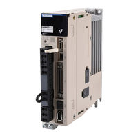
Sigma-7-Series AC Servo Drive. Sigma-7S SERVOPACK with Analog Voltage/Pulse Train References
Brand:
YASKAWA
| Category:
Controller
| Size: 11 MB
Table of Contents
Table of Contents
28
Basic Information on
28
The Σ-7 Series
41
Interpreting the Nameplate
42
Part Names
43
Model Designations
45
Interpreting SERVOPACK Model Numbers
45
Interpreting Servomotor Model Numbers
46
Combinations of Servopacks and Servomotors
47
Combinations of Rotary Servomotors and Servopacks
47
Combinations of Direct Drive Servomotors and Servopacks
48
Combinations of Linear Servomotors and Servopacks
49
Combinations of Linear Servomotors and Servopacks
50
Functions
51
Selecting a SERVOPACK
54
Ratings and Specifications
55
Ratings
55
SERVOPACK Overload Protection Characteristics
58
Ratings and Specifications
58
Specifications
59
Block Diagrams
64
SGD7S-R70A, -R90A, and -1R6A
64
Sgd7S-2R8A
64
SGD7S-3R8A, -5R5A, and -7R6A
65
Sgd7S-120A
66
SGD7S-180A and -200A
67
Sgd7S-330A
68
SGD7S-470A and -550A
69
SGD7S-590A and -780A
70
SGD7S-R70F, -R90F, and -2R1F
70
Sgd7S-2R8F
71
External Dimensions
72
Front Cover Dimensions and Connector Specifications
72
SERVOPACK External Dimensions
73
Examples of Standard Connections between Servopacks and Peripheral Devices
79
SERVOPACK Installation
81
Installation Precautions
82
Mounting Types and Orientation
83
Mounting Hole Dimensions
84
Mounting Interval
86
Installing One SERVOPACK in a Control Panel
86
Installing more than One SERVOPACK in a Control Panel
86
Monitoring the Installation Environment
87
Derating Specifications
88
EMC Installation Conditions
89
Wiring and Connecting Servopacks
92
Wiring and Connecting Servopacks
94
General Precautions
94
Countermeasures against Noise
96
Grounding
99
Basic Wiring Diagrams
100
Wiring the Power Supply to the SERVOPACK
102
Terminal Symbols and Terminal Names
102
Wiring Procedure for Main Circuit Connector
105
Power on Sequence
106
Power Supply Wiring Diagrams
107
Wiring Regenerative Resistors
113
Wiring Reactors for Harmonic Suppression
115
Wiring Servomotors
116
Terminal Symbols and Terminal Names
116
Pin Arrangement of Encoder Connector (CN2)
116
Wiring the SERVOPACK to the Encoder
117
Wiring the SERVOPACK to the Encoder
118
Wiring the SERVOPACK to the Holding Brake
123
I/O Signal Connections
124
I/O Signal Connector (CN1) Names and Functions
124
I/O Signal Connector (CN1) Pin Arrangement
127
I/O Signal Wiring Examples
128
I/O Circuits
134
Connecting Safety Function Signals
139
Pin Arrangement of Safety Function Signals (CN8)
139
I/O Circuits
139
Connecting the Other Connectors
141
Serial Communications Connector (CN3)
141
Computer Connector (CN7)
141
Analog Monitor Connector (CN5)
141
Manipulating Parameters (Pn)
145
Parameter Classification
145
Notation for Parameters
146
Parameter Setting Methods
147
Write Prohibition Setting for Parameters
149
Initializing Parameter Settings
152
Control Method Selection
154
Power Supply Type Settings for the Main Circuit and Control Circuit
155
AC Power Supply Input/DC Power Supply Input Setting
155
Single-Phase AC Power Supply Input/Three-Phase AC Power Supply Input Setting
156
Automatic Detection of Connected Motor
157
Functions and Settings for the /S-ON (Servo ON) Signal
158
Function of the /S-ON (Servo ON) Signal
158
Setting to Keep the Servo on and Supply Power to the Motor Continuously
158
Motor Direction Setting
159
Setting the Linear Encoder Pitch
160
Writing Linear Servomotor Parameters
161
Selecting the Phase Sequence for a Linear Servomotor
165
Polarity Sensor Setting
167
Polarity Detection
168
Restrictions
168
Using the /S-ON (Servo ON) Signal to Perform Polarity Detection
169
Using the /P-DET (Polarity Detection) Signal to Perform Polarity Detection
170
Detection
170
Using a Tool Function to Perform Polarity Detection
171
Overtravel and Related Settings
172
Overtravel Signals
173
Setting to Enable/Disable Overtravel
173
Motor Stopping Method for Overtravel
174
Overtravel Warnings
175
Holding Brake
177
Brake Operating Sequence
177
BK (Brake) Signal
178
Output Timing of /BK (Brake) Signal When the Servomotor Is Stopped
179
Output Timing of /BK (Brake) Signal When the Servomotor Is Operating
180
Motor Stopping Methods for Servo off and Alarms
182
Stopping Method for Servo off
183
Servomotor Stopping Method for Alarms
183
Motor Overload Detection Level
185
Detection Timing for Overload Warnings (A.910)
185
Detection Timing for Overload Warnings
185
Detection Timing for Overload Alarms (A.720)
186
Electronic Gear Settings
187
Electronic Gear Ratio Settings
188
Electronic Gear Ratio Setting Examples
191
Resetting the Absolute Encoder
192
Precautions on Resetting
192
Preparations
192
Applicable Tools
193
Operating Procedure
193
Setting the Origin of the Absolute Encoder
195
Setting the Origin of the Absolute Linear Encoder
195
Setting the Regenerative Resistor Capacity
198
Application Functions
199
I/O Signal Allocations
203
Input Signal Allocations
203
Output Signal Allocations
206
ALM (Servo Alarm) Signal
208
ALO1 to ALO3 (Alarm Code) Signals
208
WARN (Warning) Signal
209
TGON (Rotation Detection) Signal
209
S-RDY (Servo Ready) Signal
210
Operation for Momentary Power Interruptions
211
SEMI F47 Function
212
Setting the Motor Maximum Speed
214
Speed Control
215
Basic Settings for Speed Control
215
Soft Start Settings
222
Speed Reference Filter
222
Zero Clamping
223
V-CMP (Speed Coincidence Detection) Signal
225
Operation Examples for Changing the Motor Direction
226
Position Control
228
Basic Settings for Position Control
229
CLR (Position Deviation Clear) Signal Function and Settings
231
Reference Pulse Input Multiplication Switching
232
Smoothing Settings
234
COIN (Positioning Completion) Signal
235
NEAR (Near) Signal
236
Reference Pulse Inhibition Function
237
Torque Control
238
Basic Settings for Torque Control
238
Adjusting the Torque Reference Offset
239
Torque Reference Filter Settings
243
Speed Limit During Torque Control
243
Encoder Divided Pulse Output
245
Encoder Divided Pulse Output Signals
245
Setting for the Encoder Divided Pulse Output
250
Setting for the Encoder Divided Pulse Output
251
Internal Set Speed Control
252
Input Signals for Internal Set Speed Control
252
Setting the Control Method to Internal Set Speed Control
253
Settings for Internal Set Speed Control
253
Changing Internal Set Speeds with Input Signals
254
Selecting Combined Control Methods
256
Setting Pn000 = N.X (Control Method Selection) to 7, 8, or 9
256
Setting Pn000 = N.X (Control Method Selection) to a or B
259
Setting Pn000 = N.X (Control Method Selection) to 4, 5, or 6
259
Setting Pn000 = N.X (Control Method Selection) to 7, 8, or 9
259
Selecting Torque Limits
261
Internal Torque Limits
261
External Torque Limits
262
Limiting Torque with an Analog Reference
265
Reference
266
Limiting Torque with an External Torque Limit and an Analog Voltage Reference
267
CLT (Torque Limit Detection) Signal
270
Absolute Encoders
271
Connecting an Absolute Encoder
272
Structure of the Position Data of the Absolute Encoder
272
Encoder
272
Output Ports for the Position Data from the Absolute Encoder
273
Reading the Position Data from the Absolute Encoder
274
Encoder
274
Transmission Specifications
278
Calculating the Current Position in Machine Coordinates
279
Alarm Output from Output Ports for the Position Data from the Absolute Encoder
280
Multiturn Limit Setting
280
Multiturn Limit Disagreement Alarm (A.CC0)
282
Absolute Linear Encoders
285
Connecting an Absolute Linear Encoder
285
Structure of the Position Data of the Absolute Linear Encoder
285
Output Ports for the Position Data from the Absolute Linear Encoder
286
Reading the Position Data from the Absolute Linear Encoder
287
Transmission Specifications
291
Calculating the Current Position in Machine Coordinates
292
Alarm Output from the Output Ports for the Position Data from the Absolute Linear Encoder
293
Software Reset
294
Preparations
294
Applicable Tools
294
Operating Procedure
294
Initializing the Vibration Detection Level
296
Preparations
296
Applicable Tools
297
Operating Procedure
297
Related Parameters
299
Adjusting the Motor Current Detection Signal Offset
300
Automatic Adjustment
300
Manual Adjustment
302
Forcing the Motor to Stop
304
FSTP (Forced Stop Input) Signal
304
Stopping Method Selection for Forced Stops
304
Stops
304
Resetting Method for Forced Stops
306
Overheat Protection
307
Connecting the Overheat Protection Input (TH) Signal
307
Overheat Protection Selection
307
Trial Operation and Actual Operation
309
Flow of Trial Operation
310
Flow of Trial Operation for Rotary Servomotors
310
Flow of Trial Operation for Linear Servomotors
312
Inspections and Confirmations before Trial Operation
314
Trial Operation for the Servomotor Without a Load
315
Preparations
315
Applicable Tools
316
Operating Procedure
316
Trial Operation from the Host Controller for the Servomotor Without a Load
319
Preparing the Servomotor for Trial Operation
319
Trial Operation for Speed Control
321
Trial Operation for Position Control from the Host Controller with the SERVOPACK Used for Speed Control
322
Trial Operation for Position Control
323
Trial Operation with the Servomotor Connected to the Machine
325
Precautions
325
Preparations
326
Operating Procedure
326
Maintenance
327
Convenient Function to Use During Trial Operation
328
Program Jogging
328
Origin Search
333
Test Without a Motor
335
Tuning
340
Overview and Flow of Tuning
343
Tuning Functions
344
Diagnostic Tool
345
Monitoring Methods
346
Precautions to Ensure Safe Tuning
347
Overtravel Settings
347
Torque Limit Settings
347
Setting the Position Deviation Overflow Alarm Level
347
Vibration Detection Level Setting
349
Setting the Position Deviation Overflow Alarm Level at Servo on
350
Tuning-Less Function
351
Application Restrictions
351
Operating Procedure
352
Troubleshooting Alarms
353
Parameters Disabled by Tuning-Less Function
354
Automatically Adjusted Function Setting
354
Related Parameters
354
Estimating the Moment of Inertia
355
Outline
355
Restrictions
356
Applicable Tools
356
Operating Procedure
357
Autotuning Without Host Reference
363
Outline
363
Restrictions
364
Applicable Tools
365
Operating Procedure
365
Troubleshooting Problems in Autotuning Without a Host Reference
370
Automatically Adjusted Function Settings
371
Related Parameters
373
Autotuning with a Host Reference
374
Outline
374
Restrictions
374
Applicable Tools
375
Operating Procedure
375
Troubleshooting Problems in Autotuning with a Host Reference
379
Automatically Adjusted Function Settings
380
Related Parameters
380
Custom Tuning
381
Outline
381
Preparations
381
Applicable Tools
382
Operating Procedure
382
Automatically Adjusted Function Settings
388
Tuning Example for Tuning Mode 2 or 3
388
Related Parameters
389
Anti-Resonance Control Adjustment
390
Outline
390
Preparations
390
Applicable Tools
391
Operating Procedure
391
Related Parameters
393
Suppressing Different Vibration Frequencies with Anti-Resonance Control
393
Vibration Suppression
395
Outline
395
Preparations
396
Applicable Tools
396
Operating Procedure
396
Setting Combined Functions
398
Related Parameters
398
Speed Ripple Compensation
399
Outline
399
Setting up Speed Ripple Compensation
399
Setting Parameters
403
Additional Adjustment Functions
405
Gain Switching
405
Gain Switching
406
Friction Compensation
409
Gravity Compensation
410
Current Control Mode Selection
412
Current Gain Level Setting
412
Speed Detection Method Selection
413
Speed Feedback Filter
413
Proportional Control (P Control)
413
Manual Tuning
415
Tuning the Servo Gains
415
Compatible Adjustment Functions
425
Diagnostic Tools
431
Mechanical Analysis
431
Mechanical Analysis
432
Easy FFT
433
Easy FFT
434
Monitoring
437
Monitoring Product Information
438
Items that You Can Monitor
438
Operating Procedures
439
Monitoring SERVOPACK Status
440
Servo Drive Status
440
Monitoring Status and Operations
441
I/O Signal Monitor
443
Monitoring Machine Operation Status and Signal Waveforms
444
Items that You Can Monitor
444
Using the Sigmawin
445
Using a Measuring Instrument
446
Monitoring Product Life
451
Items that You Can Monitor
451
Operating Procedure
452
Preventative Maintenance
453
Alarm Tracing
454
Data for Which Alarm Tracing Is Performed
454
Applicable Tools
454
Fully-Closed System
456
SERVOPACK Commissioning Procedure
457
Parameter Settings for Fully-Closed Loop Control
459
Control Block Diagram for Fully-Closed Loop Control
459
Setting the Motor Direction and the Machine Movement Direction
460
Loop Control
460
Setting the Number of External Encoder Scale Pitches
461
Setting the PAO, PBO, and PCO (Encoder Divided Pulse Output) Signals
461
Setting the Number of External Encoder Scale
461
External Absolute Encoder Data Reception Sequence
462
Electronic Gear Setting
462
Alarm Detection Settings
462
External Absolute Encoder Data Reception
462
Analog Monitor Signal Settings
464
Setting to Use an External Encoder for Speed Feedback
464
Introduction to the Safety Functions
466
Safety Functions
466
Precautions for Safety Functions
466
Hard Wire Base Block (HWBB)
467
Risk Assessment
467
Hard Wire Base Block (HWBB) State
468
Resetting the HWBB State
468
Detecting Errors in HWBB Signal
469
HWBB Input Signal Specifications
469
Operation Without a Host Controller
469
S-RDY (Servo Ready Output) Signal
470
BK (Brake Output) Signal
470
Stopping Methods
470
Settings to Clear the Position Deviation
471
ALM (Servo Alarm) Signal and ALO1, ALO2, and ALO3
471
(Alarm Code Output) Signals
471
EDM1 (External Device Monitor)
472
EDM1 Output Signal Specifications
472
Applications Examples for Safety Functions
473
Connection Example
473
Failure Detection Method
473
Procedure
474
Validating Safety Functions
475
Connecting a Safety Function Device
476
Inspections and Part Replacement
478
Inspections
478
Guidelines for Part Replacement
478
Replacing the Battery
479
Alarm Displays
481
List of Alarms
481
List of Alarms
482
Troubleshooting Alarms
488
Resetting Alarms
518
Displaying the Alarm History
519
Clearing the Alarm History
520
Resetting Alarms Detected in Option Modules
521
Resetting Motor Type Alarms
523
Warning Displays
524
List of Warnings
524
Troubleshooting Warnings
525
Troubleshooting Based on the Operation and Conditions of the Servomotor
531
Panel Displays and Panel Operator Procedures
541
Panel Operator
541
Panel Operator Key Names and Functions
543
Changing Modes
543
Status Displays
544
Parameter (Pn) Operations on the Panel Operator
546
Setting Parameters that Require Numeric Settings
546
Setting Parameters that Require Selection of Functions
547
Monitor Display (Un) Operations on the Panel Operator
548
Basic Monitor Display Operations
548
Input Signal Monitor (Un005)
548
Output Signal Monitor (Un006)
549
Safety Input Signal Monitor (Un015)
550
Upper Limit Setting Monitor for Maximum Motor Speed/Upper Limit Setting for Encoder Output Resolution (Un010)
551
Polarity Sensor Signal Monitor (Un011)
551
Utility Function (Fn) Operations on the Panel Operator
552
Display Alarm History (Fn000)
552
Jog (Fn002)
553
Origin Search (Fn003)
554
Jog Program (Fn004)
555
Initialize Parameters (Fn005)
556
Clear Alarm History (Fn006)
556
Reset Absolute Encoder (Fn008)
557
Autotune Analog (Speed/Torque) Reference Offset (Fn009)
558
Manually Adjust Speed Reference Offset (Fn00A)
558
Manually Adjust Torque Reference Offset (Fn00B)
559
Adjust Analog Monitor Output Offset (Fn00C)
560
Adjust Analog Monitor Output Gain (Fn00D)
560
Autotune Motor Current Detection Signal Offset (Fn00E)
561
Manually Adjust Motor Current Detection Signal Offset (Fn00F)
562
Write Prohibition Setting (Fn010)
563
Display Servomotor Model (Fn011)
564
Display Software Version (Fn012)
565
Multiturn Limit Setting after Multiturn Limit Disagreement Alarm (Fn013)
566
Reset Option Module Configuration Error (Fn014)
567
Initialize Vibration Detection Level (Fn01B)
567
Display SERVOPACK and Servomotor Ids (Fn01E)
568
Display Servomotor ID from Feedback Option Module (Fn01F)
568
Set Absolute Linear Encoder Origin (Fn020)
568
Resetting Motor Type Alarms (Fn021)
569
Software Reset (Fn030)
569
Polarity Detection (Fn080)
569
Tuning-Less Level Setting (Fn200)
570
Advanced Autotuning Without Reference (Fn201)
571
Advanced Autotuning with Reference (Fn202)
571
One-Parameter Tuning (Fn203)
571
Adjust Anti-Resonance Control (Fn204)
572
Vibration Suppression (Fn205)
572
Easy FFT (Fn206)
572
Parameter Lists
574
List of Parameters
575
Interpreting the Parameter Lists
575
List of Parameters
576
Parameter Recording Table
607
Appendices
614
Examples of Connections to Host Controllers
615
Example of Connections to MP2000/MP3000-Series SVA-01
615
Motion Module
615
Example of Connections to Yokogawa Electric's F3YP2-0P Positioning Module for Position Control
616
Example of Connections to Yokogawa Electric's F3NC3-0N Positioning Module for Position Control
617
Example of Connections to an OMRON Position Control Unit
618
Example of Connection to Mitsubishi's QD75D Positioning Module for Position Control
619
Corresponding SERVOPACK and Sigmawin+ Function Names
620
Corresponding SERVOPACK Utility Function Names
620
Corresponding SERVOPACK Monitor Display Function Names
621
Advertisement
Advertisement
Related Products
YASKAWA SGD7S series
YASKAWA SGD7S-***A20****F62 Series
YASKAWA SGD7S-xxxDA0 series
YASKAWA SGDV-COA
YASKAWA SGDB Series
YASKAWA SGDV-OCA04A
YASKAWA SGD-A5AN
YASKAWA SGD-04AN
YASKAWA SGD-08AN
YASKAWA SGD-A5BN
YASKAWA Categories
Controller
DC Drives
Servo Drives
Robotics
Control Unit
More YASKAWA Manuals
Login
Sign In
OR
Sign in with Facebook
Sign in with Google
Upload manual
Upload from disk
Upload from URL