Sign In
Upload
Manuals
Brands
Juniper Manuals
Network Router
MX2010
Juniper MX2010 Manuals
Manuals and User Guides for Juniper MX2010. We have
2
Juniper MX2010 manuals available for free PDF download: Hardware Manual, Manual
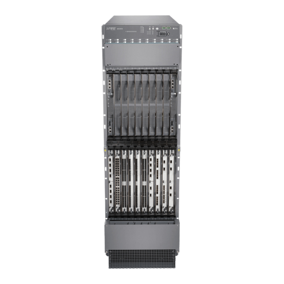
Juniper MX2010 Hardware Manual (825 pages)
Universal Routing Platform
Brand:
Juniper
| Category:
Network Router
| Size: 40.95 MB
Table of Contents
Table of Contents
3
About the Documentation
20
Documentation and Release Notes
20
Using the Examples in this Manual
20
Merging a Full Example
21
Merging a Snippet
22
Documentation Conventions
22
Documentation Feedback
25
Requesting Technical Support
25
Creating a Service Request with JTAC
26
Self-Help Online Tools and Resources
26
Overview
27
MX2010 Router Overview
29
Chassis Components and Descriptions
31
MX Series Router Architecture
32
MX2010 Chassis Description
33
MX2010 Backplane Description
39
MX2010 Component Redundancy
40
MX2010 Field-Replaceable Units
43
MX Series Router Packet Forwarding Engine (PFE) Architecture
45
Line Cards Supported on MX Series Routers
46
Dpcs
47
Fpcs and Pics
47
Mpcs and Mics
48
Switch Fabric Boards (SFB, SFB2, SFB3)
48
Mx2000 Adc
49
Routing Engines and CB-Res
49
Switch Control Boards
49
Ethernet Frame Counts and Statistics on MX Series Routers
50
Understanding Trio Layer 2 Feature Parity
50
MX2010 Router Hardware Components and CLI Terminology
51
Alarm and Display Components
55
MX2010 Craft Interface Description
55
MX2010 Component Leds on the Craft Interface
57
MX2010 Host Subsystem Leds and Buttons on the Craft Interface
57
MX2010 Line-Card Leds and Buttons on the Craft Interface
58
MX2010 Power Supply Module Leds on the Craft Interface
58
MX2010 SFB LED and Buttons on the Craft Interface
59
MX2010 Fan Tray Leds on the Craft Interface
60
MX2010 Alarm Relay Contacts on the Craft Interface
60
MX2010 Alarm Leds and Alarm Cutoff/Lamp Test Button
61
Cable and Rack Management
63
MX2010 Cable Manager Description
63
Standard Cable Manager
63
Extended Cable Manager
66
MX2010 Rack-Mounting Hardware
69
Cooling System
70
MX2010 Cooling System Description
70
MX2010 Fan Tray LED
73
Host Subsystem Components
75
MX2000 Host Subsystem CB-RE Description
75
RE-MX2000-1800X4 CB-RE Description
76
RE-MX2000-1800X4 CB-RE Front Panel
77
RE-MX2000-1800X4 CB-RE Components
78
RE-MX2000-1800X4 CB-RE Boot Sequence
79
RE-MX2000-1800X4 CB-RE Software
79
CHAPTER 6 Hostsubsystemcomponents
79
MX2000 Host Subsystem CB-RE Description | 51
79
REMX2K-X8-64G and REMX2K-X8-64G-LT CB-RE Description
80
REMX2K-X8-64G CB-RE Components
80
REMX2K-X8-64G and REMX2K-X8-64G-LT CB-RE Boot Sequence
82
REMX2K-X8-128G CB-RE Description
82
REMX2K-X8-128G CB-RE Components
83
REMX2K-X8-128G CB-RE Leds
84
REMX2K-X8-128G CB-RE Boot Sequence
85
CB-RE Leds
86
MX2000 Switch Fabric Board (SFB) Overview
90
MX2000 Switch Fabric Board LED
90
MX2000 Switch Fabric Board (SFB) Overview | 66
91
Interface Modules- Adcs, Mpcs, and Mics
92
MX2000 Adapter Card (ADC) Description
92
CHAPTER 7 Interfacemodules-Adcs,Mpcs,Andmics
93
MX2010 Modular Port Concentrator Description
93
MPC Components
95
MX2010 Modular Port Concentrator Leds | 73
95
MX2010 Modular Port Concentrator Leds
96
Mpcs Supported by MX Series Routers
96
MX2010 MPC Terminology
101
Mics Supported by MX Series Routers | 79
101
MX2010 Modular Interface Card Description
102
Mics Supported by MX Series Routers
102
MX2010 Modular Interface Card Leds
113
MX2010 Port and Interface Numbering
113
Power System
117
MX2010 Power System Description
117
MX2010 Power Midplane Description
122
MX2000 Three-Phase Delta AC Power Distribution Module Description
122
MX2000 Three-Phase Wye AC Power Distribution Module Description
124
MX2000 Seven-Feed Single-Phase AC Power Distribution Module Description
127
MX2000 Nine-Feed Single-Phase AC Power Distribution Module Description
128
MX2000 Three-Phase Delta and Wye AC Power Distribution Module Leds
129
MX2000 AC Power Supply Module Description
129
MX2010 AC Power Supply Module Leds
132
MX2010 DC Power Distribution Module (-48 V) Description
133
MX2000 DC Power Distribution Module (240 V China) Description
135
MX2010 DC Power Distribution Module (-48 V) Leds
136
MX2000 DC Power Distribution Module (240 V China) Leds
137
MX2010 DC Power Supply Module (-48 V) Description
138
MX2000 DC Power Supply Module (240 V China) Description
140
MX2010 DC Power Supply Module Leds
143
Site Planning, Preparation, and Specifications
145
CHAPTER 9 Planningandpreparingthesite
147
Overview of Preparing the Site for the MX2010 Router
147
MX2010 Cabinet Airflow Requirements
149
MX2010 Cabinet Size and Clearance Requirements
150
MX2010 Chassis Moving Guidelines
151
MX2010 Physical Specifications
152
MX2010 Rack Requirements
157
Rack Size and Strength
157
Spacing of Mounting Bracket and Flange Holes
159
Connection to the Building Structure
160
MX2010 Router Transport Kit Moving Requirements and Guidelines
160
Router Transport Kit Turning Radius
161
Router Transport Kit Requirements
161
MX2010 Router Environmental Specifications
163
MX2000 Router Grounding Specifications
164
MX2000 Series Chassis Grounding Points Specifications
164
MX2000 Series Router Grounding Cable Lug Specifications
165
MX2000 Series Router Grounding Cable Specifications
166
MX2010 Site Preparation Checklist
167
Clearance Requirements for Airflow and Hardware Maintenance for the MX2010 Router
169
Clearance Requirements for MX2010 Routers with Standard Cable Managers
169
Clearance Requirements for MX2010 Routers with Extended Cable Managers
171
Planning and Preparing the Site
147
Transceiver and Cable Specifications
173
Calculating Power Budget and Power Margin for Fiber-Optic Cables
173
Calculating Power Budget for Fiber-Optic Cable
173
Calculating Power Margin for Fiber-Optic Cable
174
Understanding Fiber-Optic Cable Signal Loss, Attenuation, and Dispersion
175
Attenuation and Dispersion in Fiber-Optic Cable
176
Signal Loss in Multimode and Single-Mode Fiber-Optic Cable
176
CB-RE and RCB Interface Cable and Wire Specifications for MX Series Routers
177
Routing Engine Interface Cable and Wire Specifications for MX Series Routers
178
Pinout Specifications
179
Connector Pinouts for MX Series CB-RE or RCB Auxillary and Console Ports
179
Connector Pinouts for an MX Series CB-RE or RCB Management Port
180
AC Power Requirements, Specifications, and Guidelines
182
MX2010 AC Power Requirements
182
MX2000 AC Power Cord Specifications
191
MX2000 AC Power System Electrical Specifications
194
AC Power Supply Input Fuses
195
MX2000 Router Grounding Specifications
196
MX2000 Series Chassis Grounding Points Specifications
197
MX2000 Series Router Grounding Cable Lug Specifications
197
MX2000 Series Router Grounding Cable Specifications
198
MX2000 Three-Phase Delta AC Power Distribution Module Electrical Specifications
199
MX2000 Three-Phase Wye AC Power Distribution Module Electrical Specifications
200
MX2000 Single-Phase AC Power Distribution Module Electrical Specifications
201
Calculating AC Power Requirements for MX2010 Routers
201
Mapping Input Power from AC Power Distribution Modules to AC Power Supply Modules on MX2000 Routers
206
DC Power Requirements, Specifications, and Guidelines
209
MX2010 DC Power Requirements
209
MX2010 DC Power Distribution Description (-48 V)
217
MX2010 DC Power Distribution (240 V China) Description
219
MX2010 DC Power (-48 V) System Electrical Specifications
221
MX2010 Router DC (240 V China) System Electrical Specifications
222
DC Power Supply Input Fuses
223
Calculating DC Power Requirements for MX2010 Routers
224
DC Power (-48 V) Circuit Breaker Requirements for the MX2010 Router
228
DC Power (240 V China) Circuit Breaker Requirements for the MX2000 Router
229
DC Power Cable Specifications for the MX2010 Router
229
Installation Overview
234
Installing an MX2010 Router Overview
234
Tools and Parts Required to Unpack the MX2010 Router
236
Tools Required to Install the MX2010 Router Using a Pallet Jack
236
Tools Required to Install the MX2010 Router Using a Router Transport Kit
237
Tools and Parts Required to Maintain the MX2010 Hardware Components
237
Tools and Parts Required for Connecting an MX2000 Router to Power
238
Tools and Parts Required for MX2010 Router Connections
239
Unpacking the Router
240
Unpacking the MX2010 Router Overview
240
Unpacking the MX2010 Router
241
Verifying the MX2010 Parts Received
245
Unpacking the MX2010 Router Transport Kit
247
Installing the Mounting Hardware
251
Installing the MX2010 Mounting Hardware for a Four-Post Rack or Cabinet
251
Installing Cage Nuts, if Needed
251
Installing the Four-Post Mounting Shelf
253
Removing the Center-Mounting Brackets
255
Installing the Router
256
Removing Components from the MX2010 Router Chassis before Installing It in a Rack
256
Removing the Power Distribution Modules before Installing an MX2010 Router
257
Removing the Power Supply Modules before Installing an MX2010 Router
260
Removing the Fan Trays before Installing an MX2010 Router
262
Removing the Sfbs before Installing an MX2010 Router
264
Removing the Mpcs and Adapter Card before Installing an MX2010 Router
265
Removing the Mpcs Without Removing an Adapter Card before Installing an MX2010 Router
266
Removing the CB-Res before Installing the MX2010 Router
267
Installing an MX2010 Router Using a Pallet Jack Overview
268
Installing the Pallet Jack Attachment
269
Installing the MX2010 Router Using a Pallet Jack with Attachment
270
Installing an MX2010 Router Using a Router Transport Kit Overview
275
Installing the Router Transport Kit on the MX2010 Router
275
Securing the MX2010 Router to the Router Transport Platform
278
Using the Router Transport Kit to Install the MX2010 Router in a Four-Post Rack
280
Using the Router Transport Kit to Install the MX2010 Router in an Open-Frame Rack
287
Reinstalling Components in the MX2010 Router after Initially Installing the Router in a Rack
292
Reinstalling the Power Distribution Modules
293
Reinstalling the Power Supply Modules
296
Reinstalling the Fan Trays
298
Reinstalling the Sfbs
300
Reinstalling the Adapter Card
301
Reinstalling the Mpcs
302
Reinstalling the CB-Res
303
Connecting the Router to Power
305
Grounding an MX2000 Router
305
Connecting AC Power to an MX2000 Router with Three-Phase Delta AC Power Distribution Modules
307
Connecting AC Power to an MX2000 Router with Three-Phase Wye AC Power Distribution Modules
311
Connecting Power to an MX2000 Single-Phase AC Power Distribution Module
316
Mapping Input Power from AC Power Distribution Modules to AC Power Supply Modules on MX2000 Routers
318
Connecting Power to a DC-Powered MX2010 Router with Power Distribution Modules
320
Connecting Power to a DC-Powered MX2000 Router with DC Power Distribution Modules
325
China)
325
Connecting an MX2000 DC Router Power Distribution Module (-48 V) Cable
326
Connecting an MX2000 DC Router Power Distribution Module (240 V China) Cable
329
Powering on the DC-Powered MX2010 Router
331
Powering on the DC-Powered (240 V China) MX2000 Router
333
Powering on a Three-Phase AC-Powered MX2000 Router
335
Troubleshooting the MX2000 Router Power System
336
Connecting the Router to the Network
353
Connecting the MX2010 Router to Management and Alarm Devices
353
Connecting an MX2000 Router to a Console or Auxiliary Device | 343
353
Connecting an MX2010 Router to an External Alarm-Reporting Device | 344
353
Connecting the MX2010 Router to a Network for Out-Of-Band Management | 342
353
Connecting an MX2000 Router to a Console or Auxiliary Device
354
Connecting an MX2010 Router to an External Alarm-Reporting Device
356
Connecting the Alarm Relay Wires to the MX2010 Craft Interface
362
Disconnecting the Alarm Relay Wires from the MX2010 Craft Interface
363
Connecting MPC or MIC Cables to the MX2010 Router
364
Initially Configuring the Router
367
Initially Configuring the MX2010 Router
367
Installing and Replacing Components
373
Installing Components
375
Installing an MX2010 Adapter Card
376
Installing the MX2010 Air Filter
377
Installing the MX2010 Craft Interface
382
Installing the MX2010 Standard DC Cable Manager
384
Installing an MX2000 Router DC Power Distribution Module (-48 V)
386
Installing an MX2000 Router DC Power Distribution Module (240 V China)
388
Installing an MX2010 DC Power Supply Module (-48 V)
391
Installing MX2000 Router DC Power Supply Modules (240 V China)
392
Installing an MX2010 Dual-Wide MIC
396
Installing the MX2010 Standard EMI Cover
398
Installing the MX2010 Extended EMI Cover
399
Installing an MX2010 Fan Tray
401
Installing the MX2010 Air Baffle
403
Installing the MX2010 Standard Cable Manager
404
Installing the MX2010 Extended Cable Manager
405
Installing the MX2010 Extended DC Cable Manager
405
Installing an MX2010 MIC
406
Installing an MX2000 SFB
410
Installing an MX2010 CB-RE
417
Installing MX2000 Router AC Power Supply Modules
419
Installing MX2000 Router DC Power Supply Modules (-48 V)
422
Installing an MX2000 Router Three-Phase Delta AC Power Distribution Module
426
Installing an MX2000 Router Three-Phase Wye AC Power Distribution Module
432
Installing an MX2000 Single-Phase AC Power Distribution Module
438
Installing an SFP or XFP into an MX2000 MPC or MIC
443
Replacing Components
445
Tools and Parts Required for Replacing MX2010 Hardware Components
446
Tools and Parts Required to Remove Components from an MX2010 Router
448
Removing a CB-RE from an MX2000 Router
449
Upgrading to the Control Board-Routing Engine REMX2K-X8-64G in a Redundant Host Subsystem
451
Taking the Host Subsystem Offline
452
Removing the Backup CB-RE
453
Installing the REMX2K-X8-64G CB-RE
454
Verifying and Configuring the Upgraded CB-RE as the Backup
455
Verifying and Configuring the Upgraded CB-RE as the Master
455
Taking the Host Subsystem Offline
456
Upgrading to the REMX2K-X8-64G CB-RE in a Nonredundant Host Subsystem
456
Removing the CB-RE
457
Installing the REMX2K-X8-64G CB-RE
458
Verifying and Configuring the Upgraded CB-RE
459
Replacing a Cable on an MX2010 MPC or MIC
460
Removing a Cable on an MX2010 MPC or MIC
460
Installing a Cable on an MX2010 MPC or MIC
461
Replacing the MX2010 Air Filters
465
Removing the MX2010 Air Filter
465
Installing the MX2010 Air Filter
470
Replacing the MX2010 Standard Cable Managers
475
Removing the MX2010 Standard Cable Manager
476
Installing the MX2010 Standard Cable Manager
477
Removing the MX2010 Standard DC Cable Manager
478
Installing the MX2010 Standard DC Cable Manager
479
Replacing the MX2010 Extended Cable Manager
480
Removing the MX2010 Extended Cable Manager
481
Removing the MX2010 Extended DC Cable Manager
481
Installing the MX2010 Extended Cable Manager
482
Installing the MX2010 Extended DC Cable Manager
483
Replacing the MX2010 Craft Interface
484
Disconnecting the Alarm Relay Wires from the MX2010 Craft Interface
484
Removing the MX2010 Craft Interface
485
Installing the MX2010 Craft Interface
488
Connecting the Alarm Relay Wires to the MX2010 Craft Interface
490
Replacing an MX2010 DC Power Supply Module (-48 V)
491
Removing an MX2010 DC Power Supply Module (-48 V)
491
Installing an MX2010 DC Power Supply Module (-48 V)
494
Replacing an MX2000 DC Power Supply Module (240 V China)
496
Removing an MX2000 Router DC Power Supply Module (240 V China)
496
Installing an MX2000 Router DC Power Supply Module (240 V China)
498
Replacing an MX2000 DC Power Distribution Module (-48 V)
500
Removing an MX2000 Router DC Power Distribution Module (-48 V)
500
Installing an MX2000 Router DC Power Distribution Module (-48 V)
504
Replacing an MX2000 DC Power Distribution Module (240 V China)
506
Removing an MX2000 Router DC Power Distribution Module (240 V China)
507
Installing an MX2000 Router DC Power Distribution Module (240 V China)
510
Replacing an MX2010 DC Power Distribution Module Cable
512
Disconnecting an MX2010 DC Power Distribution Module Cable
513
Connecting an MX2010 DC Power Distribution Module Cable
514
Connecting an MX2000 DC Router Power Distribution Module (240 V China) Cable
516
Replacing the MX2010 Standard EMI Cover
518
Removing the MX2010 Standard EMI Cover
518
Installing the MX2010 Standard EMI Cover
519
Replacing the MX2010 Extended EMI Cover
521
Removing the MX2010 Extended EMI Cover
521
Installing the MX2010 Extended EMI Cover
522
Replacing an MX2010 Fan Tray
524
Removing an MX2010 Fan Tray
525
Installing an MX2010 Fan Tray
527
Replacing the MX2010 Air Baffle
529
Installing the MX2010 Air Baffle
530
Removing the MX2010 Air Baffle | 513
530
Replacing an MX2010 MIC
531
Removing an MX2010 MIC
531
Installing an MX2010 MIC
533
Installing an MX2010 Dual-Wide MIC
536
Removing a MIC from an MPC6E
539
Replacing a MIC Installed on an MPC6E
539
Installing a MIC on an MPC6E
540
Replacing an MX2010 MPC and Adapter Card
541
Removing an MX2010 MPC with Adapter Card
541
Removing an MX2010 MPC from the Adapter Card
544
Removing an MX2010 Adapter Card
546
Installing an MX2010 Adapter Card
547
Installing an MX2010 MPC into an Adapter Card
549
Replacing an MX2000 SFB
552
Removing an MX2000 SFB
553
Installing an MX2000 SFB
555
Replacing an MX2000 CB-RE
563
Removing a CB-RE from an MX2000 Router
563
Installing an MX2020 CB-RE
565
Installing an MX2010 CB-RE
568
Replacing an SFP or XFP Transceiver on an MX2010 MPC or MIC
570
Removing an SFP or XFP from an MX2010 MPC or MIC
570
Installing an SFP or XFP into an MX2000 MPC or MIC
572
Replacing an MX2000 AC Power Supply Module
573
Removing an MX2000 AC Power Supply Module
573
Installing MX2000 Router AC Power Supply Modules
576
Replacing an MX2010 Three-Phase Delta AC Power Cord
579
Removing an MX2000 Three-Phase Delta AC Power Cord
580
Installing an MX2010 Three-Phase Delta AC Power Cord
582
Replacing an MX2000 Three-Phase Delta AC Power Distribution Module
587
Removing an MX2000 Three-Phase Delta AC Power Distribution Module
587
Installing an MX2000 Router Three-Phase Delta AC Power Distribution Module
592
Replacing an MX2010 Three-Phase Wye AC Power Cord
599
Removing an MX2000 Three-Phase Wye AC Power Cord
599
Installing an MX2010 Three-Phase Wye AC Power Cord
602
Replacing an MX2020 Three-Phase Wye AC Power Distribution Module
606
Removing an MX2000 Three-Phase Wye AC Power Distribution Module
606
Installing an MX2000 Router Three-Phase Wye AC Power Distribution Module
612
Maintaining the Chassis and Components
619
Maintaining Components
621
Maintaining the MX2010 Adapter Cards
622
Maintaining Cables that Connect to MX2010 Mpcs or Mics
623
Maintaining and Verifying the Status of the MX2010 Router Components
625
Maintaining the MX2010 Air Filters
625
Maintaining the MX2010 Air Vents
626
Maintaining the MX2010 Chassis FRU Power-On Sequence
626
Maintaining the MX2010 Control Boards
627
Maintaining the MX2010 Cooling System Components
629
Maintaining the MX2010 Air Vents
629
Maintaining the MX2010 Air Baffle
630
Maintaining the MX2010 Air Filters
630
Maintaining the MX2010 Fan Trays
631
Maintaining the MX2010 Cooling System Zones
645
Maintaining the MX2010 Ethernet Switch
646
Maintaining the MX2010 Fan Trays
649
Maintaining the MX2010 Air Baffle
662
Maintaining the MX2010 Host Subsystem
663
Maintaining the MX2010 Routing Engines
663
Maintaining the MX2010 Control Boards
665
Maintaining MX2010 Mics
667
Maintaining MX2010 Mpcs
669
Maintaining MX2010 Packet Forwarding Engine Components
672
Maintaining MX2010 Mpcs
672
Maintaining MX2010 Mics
676
Maintaining the MX2010 Ethernet Switch
678
Maintaining Cables that Connect to MX2010 Mpcs or Mics
681
Maintaining the Power Supply Modules on the MX2000 Line of Routers
682
Maintaining the MX2010 Power Usage
688
Maintaining the MX2010 Routing Engines
694
Maintaining the MX2010 SFB
696
Maintaining the MX2010 Switch Processor Mezzanine Board (SPMB)
697
Maintaining and Verifying the MX2010 Router Version
698
Maintaining and Verifying the Status of the MX2010 Craft Interface
700
Taking an MX2000 Host Subsystem Offline
701
Holding an MX2010 MPC
704
Storing an MX2010 MPC
706
Routine Maintenance Procedures for the MX2010 Router
707
Packing and Returning Components
708
Guidelines for Packing Hardware Components for Shipment
708
Packing the MX2010 Router for Shipment
709
Returning a Hardware Component to Juniper Networks, Inc
711
Powering off the Router
712
Powering off the AC-Powered MX2000 Router
712
Powering off the DC-Powered MX2000 Router
713
Troubleshooting Hardware
715
Troubleshooting Components
717
MX2010 Troubleshooting Resources
717
Command-Line Interface
717
Alarm Relay Contacts
718
Chassis and Interface Alarm Messages
718
Craft Interface Leds
718
Component Leds
719
Troubleshooting the MX2010 Cooling System
720
Troubleshooting the MX2010 Host Subsystems
723
Troubleshooting the MX2000 Router Power System
723
Troubleshooting the MX2010 Mics
739
Troubleshooting the MX2010 Mpcs
740
Contacting Customer Support and Returning the Chassis or Components
743
Contacting Customer Support
745
Locating Component Serial Numbers
746
Displaying MX2010 Router Components and Serial Numbers
746
MX2010 CB-RE Serial Number Label
752
MX2010 Chassis Serial Number Label
753
MX2010 Craft Interface Serial Number Label
754
MX2010 Fan Tray Serial Number Label
755
MX2010 MIC Serial Number Label
756
MX2010 MPC Serial Number Label
757
MX2010 Power Distribution Module Serial Number Label
758
MX2010 Power Supply Module Serial Number Label
760
MX2010 SFB Serial Number Label
762
Packing and Returning Components
764
Contacting Customer Support to Obtain Return Material Authorization
764
Guidelines for Packing Hardware Components for Shipment
765
Packing the MX2020 Router for Shipment
765
Returning a Hardware Component to Juniper Networks, Inc
769
Safety and Compliance Information
771
General Safety Guidelines and Warnings
773
Definitions of Safety Warning Levels
774
Qualified Personnel Warning
777
Fire Safety Requirements
778
Fire Suppression
778
Fire Suppression Equipment
778
Warning Statement for Norway and Sweden
779
Installation and Maintenance Safety Guidelines and Warnings
780
Installation Instructions Warning
781
Chassis and Component Lifting Guidelines
781
Ramp Warning
782
Rack-Mounting and Cabinet-Mounting Warnings
782
Grounded Equipment Warning
788
Radiation and Laser Warnings
789
Laser and LED Safety Guidelines and Warnings
789
General Laser Safety Guidelines
789
Class 1 Laser Product Warning
790
Class 1 LED Product Warning
791
Laser Beam Warning
792
Radiation from Open Port Apertures Warning
793
Maintenance and Operational Safety Guidelines and Warnings
794
Battery Handling Warning
795
Jewelry Removal Warning
796
Lightning Activity Warning
798
Operating Temperature Warning
799
Product Disposal Warning
801
Electrical Safety Guidelines and Warnings
802
General Electrical Safety Guidelines and Warnings
802
Prevention of Electrostatic Discharge Damage
803
AC Power Electrical Safety Guidelines
805
AC Power Disconnection Warning
806
DC Power Copper Conductors Warning
807
DC Power Disconnection Warning
808
DC Power Grounding Requirements and Warning
810
DC Power Wiring Sequence Warning
812
DC Power Wiring Terminations Warning
815
Midplane Energy Hazard Warning
817
Multiple Power Supplies Disconnection Warning
818
Action to Take after an Electrical Accident
818
Agency Approvals and Compliance Statements
820
Agency Approvals and Compliance Statements for the MX2010 Router
820
Agency Approvals for MX2010 Routers
820
Canada
822
Compliance Statements for EMC Requirements for the MX2010 Router
822
Compliance Statements for NEBS for the MX2010 Router
822
European Community
822
Israel
823
Japan
823
Advertisement
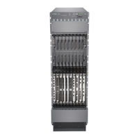
Juniper MX2010 Manual (87 pages)
Universal Routing Platform
Brand:
Juniper
| Category:
Network Router
| Size: 1.45 MB
Table of Contents
Table of Contents
2
MX2010 Quick Start Description
4
Step 1: Prepare the Site for Installation
5
Rack-Mounting Requirements
5
Moving Requirements and Guidelines Using a Router Transport Kit
8
Tools Required to Unpack and Prepare the Router for Installation
11
Step 2: Install the Mounting Hardware
12
Install the Mounting Hardware
12
Step 3: Install the Router
15
Unpack the Router
15
Remove Components
18
Install the Router Using a Pallet Jack with Attachment
25
Install the Pallet Jack Attachment
25
Use the Pallet Jack with Attachment to Install the Router
26
Install the Router Using a Router Transport Kit
32
Unpack the Router Transport Kit
32
Install the Router Transport Kit Onto the Router
36
Secure the Router to the Transport Platform
38
Use the Router Transport Kit to Install the Router in a Four-Post Rack
41
Use the Router Transport Kit to Install the Router in an Open-Frame Rack
51
Step 4: Connect the Grounding Cable
58
Step 5: Reinstall Components
59
Step 6: Connect External Devices and Line Card Cables
60
Connect to a Network for Out-Of-Band Management
61
Connect a Management Console
61
Connect the Line Card Cables
61
Step 7: Connect Power Cables
62
Connect Power to a Three-Phase Delta AC Power Distribution Module
63
Connect Power to a Three-Phase Wye AC Power Distribution Module
67
Connect AC Power Supply Modules
71
Connect Power to a DC Power Distribution Module
74
Connect DC Power Supply Modules
77
Step 8: Perform Initial Software Configuration
80
Enter Configuration Mode
81
Configure User Accounts and Passwords
81
Configure System Attributes
82
Commit the Configuration
84
Safety Warnings
85
Advertisement
Related Products
Juniper MX240
Juniper MX2020
Juniper MX240 3D
Juniper MX204
Juniper MX2008
Juniper MX480
Juniper MX960
Juniper MX Series
Juniper MX40
Juniper mx960 3D
Juniper Categories
Network Router
Switch
Gateway
Software
Network Hardware
More Juniper Manuals
Login
Sign In
OR
Sign in with Facebook
Sign in with Google
Upload manual
Upload from disk
Upload from URL