Sign In
Upload
Manuals
Brands
Juniper Manuals
Network Router
MX240
Juniper MX240 Manuals
Manuals and User Guides for Juniper MX240. We have
13
Juniper MX240 manuals available for free PDF download: Hardware Manual, Manual, Instruction For Upgrading, Quick Start Manual, Installation Instructions Manual, Datasheet, Instructions
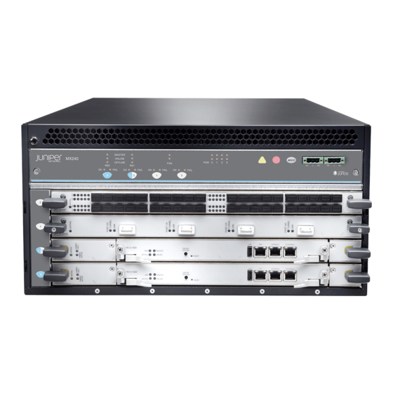
Juniper MX240 Hardware Manual (512 pages)
3D Universal Edge Router
Brand:
Juniper
| Category:
Network Router
| Size: 12.37 MB
Table of Contents
Table of Contents
3
About the Documentation
25
Documentation and Release Notes
25
Supported Platforms
25
Documentation Conventions
25
Table 1: Notice Icons
26
Table 2: Text and Syntax Conventions
26
Documentation Feedback
27
About the Documentation
27
Requesting Technical Support
28
Self-Help Online Tools and Resources
28
Opening a Case with JTAC
28
Chapter 1 System Overview
31
Chassis Components and Descriptions
31
Overview
31
Host Subsystem Components and Descriptions
31
System Overview
33
MX240 Router Overview
33
Table 3: MX240 Router Capacity
33
Table 4: SCB Comparison
34
Chapter 2 MX240 Router Release Notes
35
MX240 Router Release Notes
35
Outstanding Issues with the MX240 Router
35
Errata with the MX240 Router Documentation
36
Chapter 3 Chassis Components and Descriptions
37
MX240 Component Redundancy
37
MX240 Chassis Description
38
Figure 1: Front View of a Fully Configuredmx240 Router
38
Figure 2: Rear View of a Fully Configured AC-Poweredmx240 Router (110 V)
39
Figure 3: Rear View of a Fully Configured AC-Powered MX240 Router
39
Chassis Components and Descriptions
39
MX240 Router Hardware and CLI Terminology Mapping
40
Figure 4: Rear View of a Fully Configured DC-Poweredmx240 Router
40
Figure 5: Front View of a MPC Installed Horizontally in the MX240 Router
40
Table 5: MX240 Router Hardware Components and CLI Terminology
40
MX240 Craft Interface Overview
42
Figure 6: Front Panel of the Craft Interface
42
MX240 Alarm Relay Contacts on the Craft Interface
43
MX240 Alarm Leds and Alarm Cutoff/Lamp Test Button
43
Figure 7: Alarm Relay Contacts
43
MX240 Component Leds on the Craft Interface
44
Host Subsystem Leds on the MX240 Craft Interface
44
Table 6: Alarm Leds and Alarm Cutoff/Lamp Test Button
44
Table 7: Host Subsystem Leds on the Craft Interface
44
Power Supply Leds on the MX240 Craft Interface
45
DPC and MPC Leds on the MX240 Craft Interface
45
FPC Leds on the MX240 Craft Interface
45
Table 8: Power Supply Leds on the Craft Interface
45
Table 9: DPC and MPC Leds on the Craft Interface
45
SCB Leds on the MX240 Craft Interface
46
Fan LED on the MX240 Craft Interface
46
Table 10: FPC Leds on the Craft Interface
46
Table 11: SCB Leds on the Craft Interface
46
Table 12: Fan Leds on the Craft Interface
46
MX240 Alarm Relay Contacts on the Craft Interface
46
MX240 Alarm Leds and Alarm Cutoff/Lamp Test Button
46
Chapter 4 Cooling System Components and Descriptions
47
MX240 Cooling System Description
47
Figure 8: Airflow through the Chassis
47
MX240 Fan LED
48
Figure 9: Fan Tray
48
Figure 10: Air Filter
48
Cooling System Components and Descriptions
49
Chapter 5 Host Subsystem Components and Descriptions
51
MX240 Host Subsystem Description
51
MX240 Host Subsystem Leds
52
MX240 Midplane Description
52
Figure 11: Midplane
52
MX240 Host Subsystem Description
52
MX240 Routing Engine Description
53
Figure 12: RE-S-2000 Routing Engine
54
Figure 13: RE-S-1800
54
Figure 14: RE-S-X6-64G Routing Engine Front View
54
Figure 15: RE-S-X6-64G-LT Routing Engine Front View
55
RE-S-X6-64G and RE-S-X6-64G-LT Routing Engine Components
55
RE-S-X6-64G and RE-S-X6-64G-LT Routing Engine Interface Ports
56
Routing Engine Boot Sequence
56
Routing Engine Interface Ports
56
RE-S-1800 Routing Engine Description for MX Series
57
RE-S-1800 Routing Engine Components
57
Figure 16: RE-S-1800 Front View
57
RE-S-1800 Routing Engine Boot Sequence
58
Figure 17: Routing Engine-RE-S-1800
58
RE-S-X6-64G Routing Engine Description
59
RE-S-X6-64G Routing Engine Components
59
Figure 18: RE-S-X6-64G Routing Engine Front View
59
RE-S-X6-64G Routing Engine Boot Sequence
60
MX240 Routing Engine Leds
61
RE-S-1800 Routing Engine Leds
61
Table 13: Routing Engine Leds
61
Table 14: Routing Engine Leds
61
Figure 19: RE-S-X6-64G Routing Engine Leds
62
RE-S-X6-64G Routing Engine Leds
62
Table 15: RE-S-X6-64G Routing Engine Leds
62
Routing Engine Specifications
63
Table 16: Routing Engine Specifications
63
Table 17: End-Of-Life Routing Engine Specifications
65
Supported Routing Engines by Router
66
M7I Routing Engines
66
M10I Routing Engines
67
M40E Routing Engines
67
Table 18: M7I Routing Engines
67
Table 19: M10I Routing Engines
67
Table 20: M40E Routing Engines
67
M120 Routing Engines
68
M320 Routing Engines
68
Table 21: M120 Routing Engines
68
Table 22: M320 Routing Engines
68
MX5, MX10, MX40, and MX80 Routing Engine
69
MX104 Routing Engines
69
MX240 Routing Engines
69
Table 23: MX5, MX10, MX40, and MX80 Routing Engine
69
Table 24: MX104 Routing Engines
69
MX480 Routing Engines
70
Table 25: MX240 Supported Routing Engines
70
Table 26: MX480 Supported Routing Engines
70
MX960 Routing Engines
71
Table 27: MX960 Supported Routing Engines
71
MX2008 Routing Engines
72
MX2010 Routing Engines
72
Table 28: MX2008 Supported Routing Engines
72
Table 29: MX2010 Supported Routing Engines
72
MX2020 Supported Routing Engines
73
PTX3000 Routing Engines
73
Table 30: MX2020 Supported Routing Engines
73
Table 31: PTX3000 Routing Engines
73
PTX5000 Routing Engines
74
T320 Routing Engines
74
T640 Routing Engines
74
Table 32: PTX5000 Routing Engines
74
Table 33: T320 Routing Engines
74
T1600 Routing Engines
75
Table 34: T640 Routing Engines
75
Table 35: T1600 Routing Engines
75
T4000 Routing Engines
76
TX Matrix Routing Engines
76
Table 36: T4000 Routing Engines
76
TX Matrix Plus Routing Engines
77
TX Matrix Plus (with 3D Sibs) Routing Engines
77
Table 37: TX Matrix Routing Engines
77
Table 38: TX Matrix Plus Routing Engines
77
Table 39: Routing Engines on TX Matrix Plus with 3D Sibs
77
Table
77
Advertisement
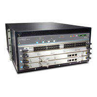
Juniper MX240 Hardware Manual (484 pages)
Universal Edge Router
Brand:
Juniper
| Category:
Network Router
| Size: 11.98 MB
Table of Contents
Table of Contents
3
About the Documentation
25
Documentation and Release Notes
25
Supported Platforms
25
Documentation Conventions
25
Table 1: Notice Icons
26
Table 2: Text and Syntax Conventions
26
Documentation Feedback
27
About the Documentation
27
Requesting Technical Support
28
Self-Help Online Tools and Resources
28
Opening a Case with JTAC
28
Chassis Components and Descriptions
31
Host Subsystem Components and Descriptions
31
System Overview
31
Overview
31
Chapter 1 System Overview
33
System Overview
33
MX240 Router Overview
33
Table 3: MX240 Router Capacity
33
Table 4: SCB Comparison
34
Chapter 2 MX240 Router Release Notes
35
Errata with the MX240 Router Documentation
36
MX240 Router Release Notes
35
Outstanding Issues with the MX240 Router
35
Chapter 3 Chassis Components and Descriptions
37
MX240 Component Redundancy
37
MX240 Chassis Description
38
Figure 1: Front View of a Fully Configuredmx240 Router
38
R E
38
Figure 2: Rear View of a Fully Configured AC-Poweredmx240 Router (110 V)
39
Figure 3: Rear View of a Fully Configured AC-Powered MX240 Router
39
Chassis Components and Descriptions
39
MX240 Router Hardware and CLI Terminology Mapping
40
Figure 4: Rear View of a Fully Configured DC-Poweredmx240 Router
40
Figure 5: Front View of a MPC Installed Horizontally in the MX240 Router
40
Table 5: MX240 Router Hardware Components and CLI Terminology
40
MX240 Craft Interface Overview
42
Figure 6: Front Panel of the Craft Interface
42
MX240 Alarm Relay Contacts on the Craft Interface
43
MX240 Alarm Leds and Alarm Cutoff/Lamp Test Button
43
Figure 7: Alarm Relay Contacts
43
MX240 Component Leds on the Craft Interface
44
Host Subsystem Leds on the MX240 Craft Interface
44
Table 6: Alarm Leds and Alarm Cutoff/Lamp Test Button
44
Table 7: Host Subsystem Leds on the Craft Interface
44
Power Supply Leds on the MX240 Craft Interface
45
DPC and MPC Leds on the MX240 Craft Interface
45
FPC Leds on the MX240 Craft Interface
45
Table 8: Power Supply Leds on the Craft Interface
45
Table 9: DPC and MPC Leds on the Craft Interface
45
SCB Leds on the MX240 Craft Interface
46
Fan LED on the MX240 Craft Interface
46
Table 10: FPC Leds on the Craft Interface
46
Table 11: SCB Leds on the Craft Interface
46
Table 12: Fan Leds on the Craft Interface
46
Chapter 4 Cooling System Components and Descriptions
47
MX240 Cooling System Description
47
Figure 8: Airflow through the Chassis
47
MX240 Fan LED
48
Figure 9: Fan Tray
48
Figure 10: Air Filter
48
Cooling System Components and Descriptions
49
Chapter 5 Host Subsystem Components and Descriptions
51
MX240 Host Subsystem Description
51
MX240 Host Subsystem Leds
52
MX240 Midplane Description
52
Figure 11: Midplane
52
Figure 12: RE-S-2000 Routing Engine
53
Figure 13: RE-S-1800
54
Figure 14: RE-S-X6-64G Routing Engine Front View
54
RE-S-X6-64G Routing Engine Components
54
RE-S-X6-64G Routing Engine Interface Ports
55
Routing Engine Interface Ports
55
Routing Engine Boot Sequence
56
MX240 Routing Engine Description
53
Figure 15: RE-S-1800 Front View
56
Figure 16: Routing Engine-RE-S-1800
57
RE-S-1800 Routing Engine Components
57
RE-S-1800 Routing Engine Boot Sequence
58
RE-S-1800 Routing Engine Description for MX Series
56
RE-S-X6-64G Routing Engine Description for MX Series
58
RE-S-X6-64G Routing Engine Components
58
Figure 17: RE-S-X6-64G Routing Engine Front View
58
RE-S-X6-64G Routing Engine Boot Sequence
59
MX240 Routing Engine Leds
60
RE-S-1800 Routing Engine Leds
60
Table 13: Routing Engine Leds
60
Table 14: Routing Engine Leds
60
Figure 18: RE-S-X6-64G Routing Engine Leds
61
RE-S-X6-64G Routing Engine Leds
61
Table 15: RE-S-X6-64G Routing Engine Leds
61
Routing Engine Specifications
62
Table
62
Table 16: Routing Engine Specifications
62
Table 17: End-Of-Life Routing Engine Specifications
63
Supported Routing Engines by Router
64
M7I Routing Engines
65
M10I Routing Engines
65
Table 18: M7I Routing Engines
65
M40E Routing Engines
66
M120 Routing Engines
66
Table 19: M10I Routing Engines
66
Table 20: M40E Routing Engines
66
Table 21: M120 Routing Engines
66
M320 Routing Engines
67
MX5, MX10, MX40, and MX80 Routing Engine
67
Table 22: M320 Routing Engines
67
MX104 Routing Engines
68
MX240 Routing Engines
68
Table 23: MX5, MX10, MX40, and MX80 Routing Engine
68
Table 24: MX104 Routing Engines
68
Table 25: MX240 Routing Engines
68
MX480 Routing Engines
69
Table 26: MX480 Routing Engines
69
MX960 Routing Engines
70
Table 27: MX960 Routing Engines
70
MX2010 Routing Engines
71
MX2020 Routing Engines
71
PTX3000 Routing Engines
71
PTX5000 Routing Engines
71
Table 28: MX2010 Routing Engines
71
Table 29: MX2020 Routing Engines
71
Table 30: PTX3000 Routing Engines
71
T320 Routing Engines
72
T640 Routing Engines
72
Table 31: PTX5000 Routing Engines
72
Table 32: T320 Routing Engines
72
T1600 Routing Engines
73
Table 33: T640 Routing Engines
73
Table 34: T1600 Routing Engines
73
T4000 Routing Engines
74
TX Matrix Routing Engines
74
Table 35: T4000 Routing Engines
74
TX Matrix Plus Routing Engines
75
TX Matrix Plus (with 3D Sibs) Routing Engines
75
Table 36: TX Matrix Routing Engines
75
Table 37: TX Matrix Plus Routing Engines
75
Table 38: Routing Engines on TX Matrix Plus with 3D Sibs
75
Fxp0 Fxp1
75
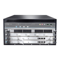
Juniper MX240 Hardware Manual (410 pages)
5G Universal Routing Platform
Brand:
Juniper
| Category:
Network Router
| Size: 11.55 MB
Table of Contents
Table of Contents
3
About the Documentation
21
Documentation and Release Notes
21
Using the Examples in this Manual
21
Merging a Full Example
22
Merging a Snippet
22
About the Documentation
23
Documentation Conventions
23
Table 1: Notice Icons
23
Table 2: Text and Syntax Conventions
24
Documentation Feedback
25
Requesting Technical Support
25
Creating a Service Request with JTAC
26
Self-Help Online Tools and Resources
26
Benefits of the MX240 Router
27
Chapter 1 Overview
27
MX240 Hardware Overview
28
Table 3: MX240 Router Capacity
28
Table 4: Switch Control Board Capacities for MX Series 5G Universal Routing Platforms (Full-Duplex)
29
Components
30
MX240 Chassis
30
MX240 Chassis Description
30
Figure 1: Front View of a Fully Configuredmx240 Router
31
Figure 2: Rear View of a Fully Configured AC-Poweredmx240 Router (110 V)
31
Figure 3: Rear View of a Fully Configured AC-Powered MX240 Router
32
Figure 4: Rear View of a Fully Configured DC-Poweredmx240 Router
32
Figure 5: Front View of a MPC Installed Horizontally in the MX240 Router
32
MX240 Router Hardware and CLI Terminology Mapping
33
Table 5: MX240 Router Hardware Components and CLI Terminology
33
MX240 Component Redundancy
34
Figure 6: Front Panel of the Craft Interface
35
MX240 Alarm Relay Contacts on the Craft Interface
35
MX240 Craft Interface Overview
35
Figure 7: Alarm Relay Contacts
36
MX240 Alarm Leds and Alarm Cutoff/Lamp Test Button
36
MX240 Component Leds on the Craft Interface
36
Table 6: Alarm Leds and Alarm Cutoff/Lamp Test Button
36
DPC and MPC Leds on the MX240 Craft Interface
37
Host Subsystem Leds on the MX240 Craft Interface
37
Power Supply Leds on the MX240 Craft Interface
37
Table 7: Host Subsystem Leds on the Craft Interface
37
Table 8: Power Supply Leds on the Craft Interface
37
FPC Leds on the MX240 Craft Interface
38
SCB Leds on the MX240 Craft Interface
38
Table 10: FPC Leds on the Craft Interface
38
Table 11: SCB Leds on the Craft Interface
38
Table 9: DPC and MPC Leds on the Craft Interface
38
Fan LED on the MX240 Craft Interface
39
Figure 8: Airflow through the Chassis
39
MX240 Cooling System
39
MX240 Cooling System Description
39
Table 12: Fan Leds on the Craft Interface
39
Figure 10: Air Filter
40
Figure 9: Fan Tray
40
MX240 Fan LED
40
MX240 System Overview
27
Mx240 AC Power System/Mx240 Power System Description
41
MX240 AC Power System
41
MX240 Power System Description
41
Figure 11: AC Power Supply
42
Figure 12: High-Capacity AC Power Supply
42
MX240 AC Power Supply Description
42
AC Power Supply Configurations
43
MX240 AC Power Supply Leds
43
AC Power Supply Electrical Specifications for the MX240 Router
44
Table 13: AC Power Supply Leds
44
Table 14: AC Power Supply Electrical Specifications
44
AC Power Circuit Breaker Requirements for the MX240 Router
45
Table 15: AC Power System Specifications
45
AC Power Cord Specifications for the MX240 Router
46
Table 16: AC Power Cord Specifications
46
Figure 13: AC Plug Types
47
Caution
48
Errata with the MX240 Router Documentation
48
MX240 DC Power Supply Description
48
MX240 DC Power System
48
DC Power Supply Configurations
49
Figure 14: DC Power Supply
49
Figure 15: High-Capacity DC Power Supply
49
Connecting Power to a DC-Powered MX240 Router with Normal-Capacity Power Supplies
50
MX240 DC Power Supply Leds
50
See also
50
Supplies
50
Table 17: Power Supply Redundancy and Power Distribution
50
Table 18: DC Power Supply Leds
50
DC Power Supply Electrical Specifications for the MX240 Router
51
Table 19: DC Power Supply Electrical Specifications
51
DC Power Circuit Breaker Requirements for the MX240 Router
52
Table 20: DC Power System Specifications
52
Figure 16: Connecting AC Power to the Router
53
MX240 Chassis Grounding Points Specifications
53
MX240 Chassis Grounding Specifications
53
Figure 17: Connecting DC Power to the Router
54
Figure 18: Grounding Cable Lug
54
MX240 Router Grounding Cable Lug Specifications
54
MX240 Router Grounding Cable Specifications
54
DC Power Source Cabling for the MX240 Router
55
Figure 19: Typical DC Source Cabling to the Router
55
DC Power Cable Specifications for the MX240 Router
56
Figure 20: DC Power Cable Lug
56
MX240 Host Subsystem Components and Descriptions
57
Outstanding Issues with the MX240 Router
57
MX240 Host Subsystem Description
58
MX240 Host Subsystem Leds
58
MX240 Midplane Description
58
Figure 21: Midplane
59
MX240 Routing Engine Description
59
Figure 22: RE-S-2000 Routing Engine
60
Figure 23: RE-S-1800
60
Figure 24: RE-S-X6-64G Routing Engine Front View
60
Figure 25: RE-S-X6-64G-LT Routing Engine Front View
61
RE-S-X6-64G and RE-S-X6-64G-LT Routing Engine Components
61
Ports
62
Routing Engine Boot Sequence
62
Routing Engine Interface Ports
62
Figure 26: RE-S-1800 Front View
63
RE-S-1800 Routing Engine Components
63
RE-S-1800 Routing Engine Description
63
RE-S-1800 Routing Engine Boot Sequence
64
RE-S-1800 Routing Engine Leds
64
Table 21: Routing Engine Leds
64
Figure 27: RE-S-X6-64G Routing Engine Front View
65
RE-S-X6-64G Routing Engine Components
65
RE-S-X6-64G Routing Engine Description
65
RE-S-X6-64G Routing Engine Boot Sequence
66
Figure 28: RE-S-X6-128G Routing Engine Front View
67
RE-S-X6-128G Routing Engine Components
67
RE-S-X6-128G Routing Engine Description
67
Figure 29: RE-S-X6-128G Routing Engine Leds
68
RE-S-X6-128G Routing Engine Leds
68
Table 22: RE-S-X6-128G Routing Engine Leds
68
MX240 Routing Engine Leds
69
RE-S-X6-128G Routing Engine Boot Sequence
69
Table 23: Routing Engine Leds
69
Figure 30: RE-S-X6-64G Routing Engine Leds
70
RE-S-1800 Routing Engine Leds
70
RE-S-X6-64G Routing Engine Leds
70
Table 24: Routing Engine Leds
70
Routing Engine Specifications
71
Table 25: RE-S-X6-64G Routing Engine Leds
71
Table 26: Routing Engine Specifications
72
Table 27: Hardware Specifications of the RE-MX-X6, RE-MX-X8, RE-PTX-X8, RCBPTX, RE-QFX10002-60C, and RE-PTX10002-60C Routing Engines
75
Table 28: End-Of-Life Routing Engine Specifications
76
M7I Routing Engines
78
Supported Routing Engines by Router
78
M10I Routing Engines
79
M40E Routing Engines
79
Table 29: M7I Routing Engines
79
Table 30: M10I Routing Engines
79
Table 31: M40E Routing Engines
79
M120 Routing Engines
80
M320 Routing Engines
80
Table 32: M120 Routing Engines
80
Table 33: M320 Routing Engines
80
MX104 Routing Engines
81
MX240 Routing Engines
81
MX5, MX10, MX40, and MX80 Routing Engine
81
Table 34: MX5, MX10, MX40, and MX80 Routing Engine
81
Table 35: MX104 Routing Engines
81
MX480 Routing Engines
82
Table 36: MX240 Supported Routing Engines
82
MX960 Routing Engines
83
Table 37: MX480 Supported Routing Engines
83
MX2008 Routing Engines
84
Table 38: MX960 Supported Routing Engines
84
MX2010 Routing Engines
85
MX2020 Supported Routing Engines
85
Table 39: MX2008 Supported Routing Engines
85
Table 40: MX2010 Supported Routing Engines
85
MX10003 Routing Engines
86
MX10008 Routing Engines
86
Table 41: MX2020 Supported Routing Engines
86
Table 42: MX10003 Supported Routing Engines
86
PTX1000 Routing Engines
87
PTX3000 Routing Engines
87
PTX5000 Routing Engines
87
Table 43: MX10008 Routing Engines
87
Table 44: PTX1000 Routing Engines
87
Table 45: PTX3000 Routing Engines
87
PTX10008 and PTX10016 Routing Engines
88
Table 46: PTX5000 Routing Engines
88
Table 47: PTX10008 and PTX10016 Routing Engines
88
T320 Routing Engines
89
T640 Routing Engines
89
Table 48: T320 Routing Engines
89
Table 49: T640 Routing Engines
89
T1600 Routing Engines
90
Table 50: T1600 Routing Engines
90
T4000 Routing Engines
91
Table 51: T4000 Routing Engines
91
TX Matrix Routing Engines
91
Table 52: TX Matrix Routing Engines
92
Table 53: TX Matrix Plus Routing Engines
92
TX Matrix Plus (with 3D Sibs) Routing Engines
92
TX Matrix Plus Routing Engines
92
Interface Modules-Dpcs
93
MX240 Dense Port Concentrator (DPC) Description
93
MX240 Line Card Components and Descriptions
93
Table 54: Routing Engines on TX Matrix Plus with 3D Sibs
93
Figure 31: Typical Dpcs Supported on the MX240 Router
94
Figure 32: DPC Installed Horizontally in the MX240 Router
94
MX240 DPC Port and Interface Numbering
95
Figure 33: MX240 DPC Interface Port Mapping
96
Dpcs Supported on MX240, MX480, and MX960 Routers
98
MX240 Dense Port Concentrator (DPC) Leds
98
Table 55: Dpcs Supported in MX240, MX480, and MX960 Routers
99
Interface Modules-Fpcs and Pics
101
MX240 Flexible PIC Concentrator (FPC) Description
101
Figure 34: Typical Fpcs Supported on the MX240 Router
102
Figure 35: FPC Installed in the MX240 Router Chassis
103
MX240 Flexible PIC Concentrator (FPC) Leds
103
Fpcs Supported by MX240, MX480, and MX960 Routers
104
MX240 PIC Description
104
Table 56: Fpcs Supported by MX Series Routers
104
MX240 PIC Port and Interface Numbering
105
Figure 36: MX240 PIC Interface Port Mapping
106
MX240 PIC Leds
106
Pics Supported by MX240, MX480, and MX960 Routers
107
Table 57: Pics Supported by MX240, MX480, and MX960 Routers
107
Interface Modules-Mpcs and Mics
108
MIC/MPC Compatibility
108
Table 58: MIC/MPC1 Compatibility
108
Table 59: MIC/MPC2 Compatibility
110
Advertisement
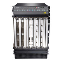
Juniper MX240 Hardware Manual (510 pages)
Universal Routing Platform.
Brand:
Juniper
| Category:
Network Router
| Size: 10.87 MB
Table of Contents
Table of Contents
3
About the Documentation
18
Documentation and Release Notes
18
Using the Examples in this Manual
18
Merging a Full Example
19
Merging a Snippet
20
Documentation Conventions
20
Documentation Feedback
23
Requesting Technical Support
23
Creating a Service Request with JTAC
24
Self-Help Online Tools and Resources
24
1 Overview
25
MX240 System Overview
27
Benefits of the MX240 Router
27
MX240 Hardware Overview
28
MX240 Chassis
30
MX240 Chassis Description
30
MX240 Router Hardware and CLI Terminology Mapping
33
MX240 Component Redundancy
35
MX240 Craft Interface Overview
36
MX240 Alarm Relay Contacts on the Craft Interface
37
MX240 Alarm Leds and Alarm Cutoff/Lamp Test Button
37
MX240 Component Leds on the Craft Interface
38
Host Subsystem Leds on the MX240 Craft Interface
38
Power Supply Leds on the MX240 Craft Interface
39
DPC and MPC Leds on the MX240 Craft Interface
39
FPC Leds on the MX240 Craft Interface
40
SCB Leds on the MX240 Craft Interface
40
Fan LED on the MX240 Craft Interface
41
MX240 Cooling System
41
MX240 Cooling System Description
42
MX240 Fan LED
43
MX240 AC Power System
44
MX240 Power System Description
44
MX240 AC Power Supply Description
45
AC Power Supply Configurations
46
MX240 AC Power Supply Leds
47
AC Power Supply Electrical Specifications for the MX240 Router
48
AC Power Circuit Breaker Requirements for the MX240 Router
49
AC Power Cord Specifications for the MX240 Router
49
Errata with the MX240 Router Documentation
52
MX240 DC Power System
53
MX240 DC Power Supply Description
53
DC Power Supply Configurations
54
MX240 DC Power Supply Leds
55
DC Power Supply Electrical Specifications for the MX240 Router
56
DC Power Circuit Breaker Requirements for the MX240 Router
58
MX240 Chassis Grounding Specifications
59
MX240 Chassis Grounding Points Specifications
59
MX240 Router Grounding Cable Lug Specifications
60
MX240 Router Grounding Cable Specifications
61
DC Power Source Cabling for the MX240 Router
61
DC Power Cable Specifications for the MX240 Router
63
Outstanding Issues with the MX240 Router
64
MX240 Host Subsystem Components and Descriptions
64
MX240 Host Subsystem Description
65
MX240 Host Subsystem Leds
66
MX240 Midplane Description
66
MX240 Routing Engine Description
67
RE-S-X6-64G and RE-S-X6-64G-LT Routing Engine Components
69
RE-S-X6-64G and RE-S-X6-64G-LT Routing Engine Interface Ports
70
Routing Engine Interface Ports
70
RE-S-1800 Routing Engine Description
71
Routing Engine Boot Sequence
71
RE-S-1800 Routing Engine Components
72
RE-S-1800 Routing Engine Boot Sequence
73
RE-S-1800 Routing Engine Leds
73
RJ-45 Connector Pinouts for an MX Series Routing Engine ETHERNET
73
RE-S-X6-64G Routing Engine Description
74
RE-S-X6-64G Routing Engine Components
74
RE-S-X6-64G Routing Engine Boot Sequence
75
RE-S-X6-128G Routing Engine Description
76
RE-S-X6-128G Routing Engine Components
76
RE-S-X6-128G Routing Engine Leds
77
RE-S-X6-128G Routing Engine Boot Sequence
79
MX240 Routing Engine Leds
79
RE-S-1800 Routing Engine Leds
80
RE-S-X6-64G Routing Engine Leds
80
Routing Engine Specifications
82
Supported Routing Engines by Router
90
M10I Routing Engines
91
M7I Routing Engines
91
M120 Routing Engines
92
M40E Routing Engines
92
M320 Routing Engines
93
MX104 Routing Engines
94
MX5, MX10, MX40, and MX80 Routing Engine
94
MX204 Routing Engine
95
MX240 Routing Engines
95
MX480 Routing Engines
96
MX960 Routing Engines
98
MX2008 Routing Engines
99
MX2010 Routing Engines
99
MX2020 Supported Routing Engines
100
MX10003 Routing Engines
101
MX10008 Routing Engines
101
PTX1000 Routing Engines
102
PTX3000 Routing Engines
102
PTX5000 Routing Engines
103
PTX10008 and PTX10016 Routing Engines
104
T320 Routing Engines
104
T640 Routing Engines
105
T1600 Routing Engines
106
T4000 Routing Engines
107
TX Matrix Routing Engines
108
TX Matrix Plus (with 3D Sibs) Routing Engines
109
TX Matrix Plus Routing Engines
109
MX240 Line Card Components and Descriptions
110
Interface Modules-Dpcs
110
MX240 Dense Port Concentrator (DPC) Description
111
MX240 DPC Port and Interface Numbering
113
Dpcs Supported on MX240, MX480, and MX960 Routers
117
MX240 Dense Port Concentrator (DPC) Leds
117
Interface Modules-Fpcs and Pics
120
MX240 Flexible PIC Concentrator (FPC) Description
121
MX240 Flexible PIC Concentrator (FPC) Leds
122
Fpcs Supported by MX240, MX480, and MX960 Routers
123
MX240 Flexible PIC Concentrator (FPC) Description | 123
123
MX240 PIC Description
123
MX240 PIC Leds | 128
124
MX240 PIC Port and Interface Numbering
124
Pics Supported by MX240, MX480, and MX960 Routers | 128
124
MX240 PIC Leds
126
Pics Supported by MX240, MX480, and MX960 Routers
126
Interface Modules-Mpcs and Mics
127
MIC/MPC Compatibility
128
MX240 Modular Interface Card (MIC) Description
137
Mics Supported by MX Series Routers
138
MX240 Modular Interface Card (MIC) Leds
148
MX240 MIC Port and Interface Numbering
148
MX240 Modular Port Concentrator (MPC) Description
152
Mpcs Supported by MX Series Routers
154
MX240 Modular Port Concentrator (MPC) Leds
154
MX240 Application Services Modular Line Card Description
159
MX240 Application Services Modular Processing Card Description
162
MX240 as MSC Leds
162
MX240 as MXC Leds
163
Services Processing Card-MX-SPC3 Services Card
164
MX-SPC3 Services Card Overview and Support on MX240, MX480, and MX960 Routers
164
MX-SPC3 Services Card
165
MX-Series Switch Control Board (SCB) Description
169
CLI Identification
171
Juniper MX240 Hardware Manual (344 pages)
3D Universal Edge Router
Brand:
Juniper
| Category:
Network Router
| Size: 9.19 MB
Table of Contents
Hardware Guide
1
Table of Contents
5
About the Documentation
21
Documentation Conventions
21
JUNOS Documentation and Release Notes
21
Table 1: Notice Icons
21
Table 2: Text and Syntax Conventions
22
About the Documentation
23
Documentation Feedback
23
Requesting Technical Support
23
Self-Help Online Tools and Resources
23
Opening a Case with JTAC
24
MX240 3D Universal Edge Router Overview
25
MX240 Hardware Components
25
MX240 Router Description
25
Chapter 1 MX240 Router Description
27
MX240 Router Overview
27
MX240 Router Hardware and CLI Terminology Mapping
28
Table 3: MX240 Router Hardware Components and CLI Terminology
28
MX240 Component Redundancy
30
Chapter 2 MX240 Hardware Components
31
MX240 Chassis Description
31
Figure 1: Front View of a Fully Configured Routers Chassis
32
Figure 2: Rear View of a Fully Configured AC-Powered Routers Chassis
32
MX240 Midplane Description
33
Figure 3: Rear View of a Fully Configured AC-Powered Routers Chassis (220 V)
33
Figure 4: Rear View of a Fully Configured DC-Powered Routers Chassis
33
MX240 Hardware Components
33
MX240 Dense Port Concentrator (DPC) Overview
34
Figure 5: Midplane
34
MX240 Dense Port Concentrator (DPC) Description
34
Figure 6: Typical Dpcs Supported on the MX240 Router
35
DPC Components
36
Figure 7: DPC Installed Horizontally in the MX240 Router
36
MX240 Dense Port Concentrator (DPC) Leds
36
MX240 DPC Port and Interface Numbering
37
Figure 8: MX240 DPC Interface Port Mapping
38
MX240 Flexible PIC Concentrator (FPC) Overview
39
Figure 9: Typical Fpcs Supported on the MX240 Router
39
MX240 Flexible PIC Concentrator (FPC) Description
39
Figure 10: FPC Installed in the MX240 Router Chassis
40
FPC Components
40
MX240 Flexible PIC Concentrator (FPC) Leds
40
Fpcs Supported by the MX240 Router
41
MX240 PIC Overview
41
MX240 PIC Description
41
Table 4: Fpcs Supported by MX240 Routers
41
MX240 PIC Leds
42
MX240 PIC Port and Interface Numbering
42
Figure 11: MX240 PIC Interface Port Mapping
43
MX240 Modular Port Concentrator (MPC) Overview
44
MX240 Modular Port Concentrator (MPC) Description
44
Figure 12: Typical MPC Supported on the MX240 Router
45
Figure 13: MPC Installed Horizontally in the MX240 Router
45
MPC Components
45
MX240 Modular Port Concentrator (MPC) Leds
46
MX240 Modular Interface Card (MIC) Description
46
MX240 MIC Port and Interface Numbering
47
MX240 Modular Interface Card (MIC) Leds
47
Figure 14: MX240 MIC Interface Port Mapping
49
MX240 Host Subsystem Overview
50
MX240 Host Subsystem Description
50
MX240 Host Subsystem Leds
51
MX240 Switch Control Board (SCB) Overview
51
MX240 Switch Control Board (SCB) Description
51
Figure 15: SCB
52
SCB Components
52
SCB Redundancy
52
SCB Slots
52
MX240 Enhanced Switch Control Board Description
53
MX240 SCB Leds
53
Table 5: SCB Leds
53
Figure 16: MX SCBE
54
MX SCBE Redundancy
54
MX SCBE Slots
54
MX SCBE Components
55
MX240 Enhanced Switch Control Board Leds
55
Table 6: Enhanced MX SCB Leds
55
MX240 Routing Engine Overview
56
Figure 17: Routing Engine
57
Figure 18: RE-S-1800
57
MX240 Routing Engine Description
57
RE-S-1800 Routing Engine Description for MX Series
58
Routing Engine Boot Sequence
58
Routing Engine Components
58
Routing Engine Interface Ports
58
Figure 19: RE-S-1800 Front View
59
Figure 20: Routing Engine-RE-S-1800
59
RE-S-1800 Routing Engine Components
59
MX240 Routing Engine Leds
60
RE-S-1800 Routing Engine Boot Sequence
60
Table 7: Routing Engine Leds
60
RE-S-1800 Routing Engine Leds
61
MX240 Craft Interface Description
61
MX240 Craft Interface Overview
61
Table 8: Routing Engine Leds
61
Figure 21: Front Panel of the Craft Interface
62
MX240 Alarm Leds and Alarm Cutoff/Lamp Test Button
62
Host Subsystem Leds on the MX240 Craft Interface
63
MX240 Component Leds on the Craft Interface
63
Table 10: Host Subsystem Leds on the Craft Interface
63
Table 9: Alarm Leds and Alarm Cutoff/Lamp Test Button
63
DPC and MPC Leds on the MX240 Craft Interface
64
FPC Leds on the MX240 Craft Interface
64
Power Supply Leds on the MX240 Craft Interface
64
Table 11: Power Supply Leds on the Craft Interface
64
Table 12: DPC and MPC Leds on the Craft Interface
64
Table 13: FPC Leds on the Craft Interface
64
Fan LED on the MX240 Craft Interface
65
MX240 Alarm Relay Contacts on the Craft Interface
65
SCB Leds on the MX240 Craft Interface
65
Table 14: SCB Leds on the Craft Interface
65
Table 15: Fan Leds on the Craft Interface
65
MX240 Power Supplies Description
66
Figure 22: Alarm Relay Contacts
66
MX240 Power System Overview
66
Figure 23: AC Power Supply
67
Figure 24: High-Capacity AC Power Supply
67
MX240 AC Power Supply Description
67
AC Power Supply Configurations
68
MX240 AC Power Supply Leds
68
MX240 DC Power Supply Description
69
Table 16: AC Power Supply Leds
69
DC Power Supply Configurations
70
Figure 25: DC Power Supply
70
Figure 26: High-Capacity DC Power Supply
70
MX240 DC Power Supply Leds
71
Table 17: DC Power Supply Leds
71
MX240 Cooling System Overview
72
Figure 27: Airflow through Chassis
72
MX240 Cooling System Description
72
Figure 28: Fan Tray
73
Figure 29: Air Filter
73
MX240 Fan LED
73
Setting up the MX240 Router
75
Chapter 3 MX240 Router Installation Overview
77
Installing an MX240 Router Overview
77
Chapter 4 Preparing the Site for MX240 Router Installation
79
MX240 Site Preparation Checklist
79
Table 18: Site Preparation Checklist
79
MX240 Router Rack Requirements
80
MX240 Router Clearance Requirements for Airflow and Hardware
80
Table 19: Rack Requirements and Specifications for an MX240 Router
80
Figure 30: Typical Open-Frame Rack
82
Maintenance
82
MX240 Router Cabinet Requirements
83
Figure 31: Chassis Dimensions and Clearance Requirements
83
MX240 Router Cabinet Size and Clearance Requirements
83
Figure 32: Airflow through Chassis
84
MX240 Router Cabinet Airflow Requirements
84
Chapter 5 Unpacking the MX240 Router
85
Tools and Parts Required to Unpack the MX240 Router
85
Figure 33: Contents of the Shipping Crate
86
Verifying the MX240 Router Parts Received
87
Table 20: Parts List for a Fully Configured Routers
87
Table 21: Accessory Box Parts List
88
Chapter 6 Installing the MX240 Router Mounting Hardware
89
Installing the MX240 Router Mounting Hardware for a Rack or Cabinet
89
Table 22: Four-Post Rack or Cabinet Mounting Hole Locations
89
Figure 34: Installing the Front Mounting Hardware for a Four-Post Rack or
90
Moving the Mounting Brackets for Center-Mounting the MX240 Router
91
Figure 35: Installing the Mounting Hardware for an Open-Frame Rack
91
Chapter 7 Installing the MX240 Router with a Mechanical Lift
93
Tools Required to Install the MX240 Router with a Mechanical Lift
93
Removing Components from the MX240 Router before Installing It with a
93
Lift
93
Removing the Power Supplies before Installing the MX240 Router with a
93
Figure 36: Removing a Power Supply before Installing the Router
94
Lift
94
Removing the Fan Tray before Installing the MX240 Router with a Lift
94
Figure 37: Removing the Fan Tray
95
Removing the Scbs before Installing the MX240 Router with a Lift
95
Figure 38: Removing an SCB
96
Removing the Dpcs before Installing the MX240 Router with a Lift
96
Figure 39: Removing a DPC
97
Removing the FPC before Installing the MX240 Router with a Lift
97
Installing the MX240 Router Using a Mechanical Lift
98
Figure 40: Removing an FPC
98
Figure 41: Installing the Router in the Rack
99
Reinstalling Components in the MX240 Router after Installing It with a Lift
100
Figure 42: Reinstalling a Power Supply
100
Lift
100
Reinstalling the Power Supplies after Installing the MX240 Router with a
100
Figure 43: Reinstalling a Fan Tray
101
Reinstalling the Fan Tray after Installing the MX240 Router with a Lift
101
Reinstalling the Scbs after Installing the MX240 Router with a Lift
101
Figure 44: Reinstalling an SCB
102
Reinstalling the Dpcs after Installing the MX240 Router with a Lift
102
Figure 45: Reinstalling a DPC
103
Figure 46: Reinstalling an FPC
103
Reinstalling the Fpcs after Installing the MX240 Router with a Lift
103
Chapter 8 Installing the MX240 Router Without a Mechanical Lift
105
Tools Required to Install the MX240 Router Without a Mechanical Lift
105
Removing Components from the MX240 Router before Installing It Without a
105
Lift
105
Figure 47: Removing a Power Supply before Installing the Router
106
Lift
106
Removing the Fan Tray before Installing the MX240 Router Without a
106
Removing the Power Supplies before Installing the MX240 Router Without
106
Figure 48: Removing the Fan Tray
107
Removing the Scbs before Installing the MX240 Router Without a Lift
107
Removing the Dpcs before Installing the MX240 Router Without a Lift
108
Figure 49: Removing an SCB
108
Removing the FPC before Installing the MX240 Router Without a Lift
109
Figure 50: Removing a DPC
109
Figure 51: Removing an FPC
110
Installing the MX240 Chassis in the Rack Manually
110
Reinstalling Components in the MX240 Router after Installing It Without a
110
Figure 52: Installing the Router in the Rack
111
Lift
112
Figure 53: Reinstalling a Power Supply
113
Figure 54: Reinstalling a Fan Tray
113
Lift
113
Figure 55: Reinstalling an SCB
114
Reinstalling the Dpcs after Installing the MX240 Router Without a Lift
114
Reinstalling the Scbs after Installing the MX240 Router Without a Lift
114
Figure 56: Reinstalling a DPC
115
Reinstalling the Fpcs after Installing the MX240 Router Without a Lift
115
Figure 57: Reinstalling an FPC
116
Chapter 9 Connecting the MX240 Router
117
Connecting the MX240 Router to Management and Alarm Devices
117
Connecting the MX240 Router to a Management Console or Auxiliary
117
Management
117
Device
118
Figure 58: Ethernet Port
118
Figure 59: Routing Engine Ethernet Cable Connector
118
Connecting the MX240 Router to an External Alarm-Reporting Device
119
Figure 60: Auxiliary and Console Ports
119
Figure 61: Routing Engine Console and Auxiliary Cable Connector
119
Figure 62: Alarm Relay Contacts
119
Tools and Parts Required for MX240 Router Connections
117
Connecting DPC, MPC, MIC, or PIC Cables to the MX240 Router
120
Figure 63: Attaching a Cable to a DPC
121
Figure 64: Attaching a Cable to a MIC
121
Chapter 10 Grounding and Providing Power to the MX240 Router
123
Tools and Parts Required for MX240 Router Grounding and Power
123
Connections
123
Grounding the MX240 Router
124
Power Supplies
125
Figure 65: Connecting AC Power to the Routers
126
Installing the MX240 AC High-Capacity Power Supplies
126
Powering on an AC-Powered MX240 Router
127
Figure 66: Installing a High-Capacity AC Power Supply
127
Supplies
128
Figure 67: Connecting DC Power to the Router
130
Figure 68: DC High-Capacity Power Supply Input Mode Switch
131
Installing an MX240 DC High-Capacity Power Supply
131
Powering on a DC-Powered MX240 Router
132
Powering off the MX240 Router
134
Chapter 11 Configuring Junos os
135
Configuring Junos os
135
Initially Configuring the MX240 Router
135
Chapter 12 Maintaining MX240 Router Hardware Components
141
Routine Maintenance Procedures for the MX240 Router
141
Tools and Parts Required to Maintain the MX240 Router
141
Maintaining the MX240 Cooling System Components
142
Maintaining the MX240 Air Filter
142
Maintaining the MX240 Fan Tray
142
Maintaining the MX240 Host Subsystem
144
Maintaining MX240 Packet Forwarding Engine Components
146
Maintaining MX240 Dpcs
146
Maintaining MX240 Fpcs
148
Maintaining MX240 Pics
149
Maintaining MX240 Mpcs
150
Maintaining MX240 Mics
151
Maintaining Cables that Connect to MX240 Dpcs, Mpcs, Mics, or Pics
152
Holding and Storing MX Series Dpcs
153
MX240 DPC Terminology
153
Figure 69: DPC Edges
154
Holding an MX240 DPC
154
Figure 70: Do Not Grasp the Connector Edge
155
Figure 71: Do Not Rest the DPC on an Edge
156
Storing an MX240 DPC
156
Holding and Storing MX Series Fpcs
157
MX240 FPC Terminology
157
Figure 72: FPC Edges
158
Holding an MX240 FPC
158
Figure 73: Do Not Grasp the Connector Edge
159
Figure 74: Do Not Carry an FPC with Only One Hand
160
Figure 75: Do Not Rest the FPC on an Edge
160
Figure 76: Holding an FPC Vertically
161
Storing an MX240 FPC
162
Figure 77: Do Not Stack Fpcs
162
Maintaining the MX240 Power Supplies
162
Chapter 13 Troubleshooting MX240 Hardware Components
165
Troubleshooting Resources for MX240 Routers
165
Command-Line Interface
165
Alarm Relay Contacts
166
Chassis and Interface Alarm Messages
166
Craft Interface Leds
166
Component Leds
167
Juniper Networks Technical Assistance Center
167
Troubleshooting the MX240 Cooling System
168
Troubleshooting the MX240 Dpcs
168
Troubleshooting the MX240 Fpcs
169
Troubleshooting the MX240 Mpcs
171
Troubleshooting the MX240 Pics
171
Troubleshooting the MX240 Mics
172
Troubleshooting the MX240 Power System
173
Chapter 14 Replacing MX240 Hardware Components
175
Table 23: Field-Replaceable Units
176
Tools and Parts Required to Replace MX240 Hardware Components
176
Table 24: Tools and Parts Required to Replace Hardware Components
177
Replacing the MX240 Air Filter
178
Removing the MX240 Air Filter
178
Figure 78: Removing the Air Filter
179
Installing the MX240 Air Filter
179
Replacing the MX240 Craft Interface
180
Disconnecting the Alarm Relay Wires from the MX240 Craft Interface
180
Figure 79: Installing the Air Filter
180
Figure 80: Alarm Relay Contacts
181
Figure 81: Removing the Craft Interface
181
Installing the MX240 Craft Interface
181
Removing the MX240 Craft Interface
181
Connecting the Alarm Relay Wires to the MX240 Craft Interface
182
Figure 82: Installing the Craft Interface
182
Figure 83: Alarm Relay Contacts
182
Replacing the MX240 Fan Tray
183
Figure 84: Removing the Fan Tray
183
Removing the MX240 Fan Tray
183
Installing the MX240 Normal-Capacity Fan Tray
184
Figure 85: Installing the Fan Tray
184
Installing the MX240 High-Capacity Fan Tray
184
Replacing MX240 Host Subsystem Components
185
Effect of Taking the MX240 Host Subsystem Offline
185
Figure 86: Reinstalling a Fan Tray
185
Table 25: Effect of Taking the Host Subsystem Offline
186
Taking an MX240 Host Subsystem Offline
187
Operating and Positioning the MX240 SCB Ejectors
188
Replacing an MX240 SCB
188
Figure 87: Removing an SCB
189
Removing an MX240 SCB
189
Installing an MX240 SCB
190
Figure 88: Installing an SCB
191
Upgrading an MX240 SCB
191
Removing an MX240 Routing Engine
198
Replacing an MX240 Routing Engine
198
Figure 89: Removing a Routing Engine
199
Figure 90: Installing a Routing Engine
200
Installing an MX240 Routing Engine
200
Figure 91: RE-A-1800 Storage Drive Slots
201
Figure 92: RE-S-1800 Storage Drive Slots
201
Replacing an SSD Drive on an RE-A-1800 or RE-S-1800
201
Replacing Connections to MX240 Routing Engine Interface Ports
202
Replacing the Management Ethernet Cable on an MX240 Router
202
Figure 93: Cable Connector
203
Figure 94: Ethernet Port
203
Figure 95: Auxiliary and Console Ports
203
Replacing the Console or Auxiliary Cable on an MX240 Router
203
Replacing an MX240 DPC
204
Removing an MX240 DPC
204
Figure 96: Removing a DPC
206
Installing an MX240 DPC
206
Figure 97: Installing a DPC
207
Replacing an MX240 FPC
208
Figure 98: Attaching a Cable to a DPC
208
Removing an MX240 FPC
208
Figure 99: Removing an FPC
210
Installing an MX240 FPC
210
Replacing an MX240 PIC
212
Figure 100: Installing an FPC
212
Removing an MX240 PIC
212
Figure 101: Removing a PIC
214
Installing an MX240 PIC
214
Replacing an MX240 MPC
216
Figure 102: Installing a PIC
216
Removing an MX240 MPC
217
Figure 103: Removing an MPC
218
Installing an MX240 MPC
219
Figure 104: Installing an MPC
220
Replacing an MX240 MIC
221
Removing an MX240 MIC
221
Figure 105: Removing a MIC
222
Figure 106: Removing a Dual-Wide MIC
222
Figure 107: Installing the Septum
223
Installing an MX240 MIC
223
Figure 108: Installing a MIC
224
Figure 109: Removing the Septum
225
Installing an MX240 Dual-Wide MIC
225
Figure 110: Installing a Dual-Wide MIC
226
Replacing a Cable on an MX240 DPC, MPC, MIC, or PIC
227
Removing a Cable on an MX240 DPC, MPC, MIC, or PIC
227
Installing a Cable on an MX240 DPC, MPC, MIC, or PIC
228
Removing an SFP or XFP Transceiver from an MX240 DPC, MPC, MIC, or PIC
230
Replacing an SFP or XFP Transceiver from an MX240 DPC, MPC, MIC, or PIC
230
Figure 111: Removing Sfps or Xfps
231
Installing an SFP or XFP Transceiver into an MX240 DPC, MPC, MIC, or PIC
231
Removing an MX240 AC Normal-Capacity Power Supply
232
Replacing an MX240 AC Normal-Capacity Power Supply
232
Replacing MX240 Power System Components
232
Figure 112: Removing an AC Power Supply
233
Installing an MX240 AC Normal-Capacity Power Supply
233
Figure 113: Installing an AC Power Supply
234
Removing an MX240 DC Normal-Capacity Power Supply
234
Replacing an MX240 DC Normal-Capacity Power Supply
234
Figure 114: Removing a DC Power Supply from the Router
235
Installing an MX240 DC Normal Capacity Power Supply
236
Figure 115: Installing a DC Power Supply in the Router
238
Figure 116: Connecting DC Power to the Router
238
Replacing an MX240 AC Power Supply Cord
238
Connecting an MX240 AC Power Supply Cord
239
Disconnecting an MX240 AC Power Supply Cord
239
Replacing an MX240 DC Power Supply Cable
239
Connecting an MX240 DC Power Supply Cable
240
Disconnecting an MX240 DC Power Supply Cable
240
Figure 117: Connecting Power Cables to the DC Power Supply
241
Appendixes
243
Juniper MX240 Hardware Manual (242 pages)
Ethernet Services Router
Brand:
Juniper
| Category:
Network Router
| Size: 5.13 MB
Table of Contents
Hardware Guide
1
Table of Contents
5
About this Guide
17
Audience
17
Documentation Conventions
17
Objectives
17
Table 1: Notice Icons
18
Table 2: Text and Syntax Conventions
18
List of Technical Publications
19
Table 3: Technical Documentation for Supported Routing Platforms
20
Table 4: JUNOS Software Network Operations Guides
24
Table 5: JUNOS Software with Enhanced Services Documentation
24
Table 6: Additional Books Available through Http://Www.juniper.net/Books
25
Documentation Feedback
26
Obtaining Documentation
26
Requesting Technical Support
27
Part
29
MX240 Router Overview
29
Chapter 1 Router Overview
31
Router Description
31
Component Redundancy
31
Chapter 2 Hardware Components
33
Midplane
33
Router Chassis
33
Figure 1: Front View of a Fully Configured Router Chassis
34
Figure 2: Rear View of a Fully Configured AC-Powered Router Chassis
34
Figure 3: Rear View of a Fully Configured AC-Powered Router Chassis
35
Figure 4: Rear View of a Fully Configured DC-Powered Router Chassis
35
Figure 6: Typical Dpcs Supported on the MX240 Router
37
Figure 7: DPC Installed Horizontally in the MX240 Router
37
DPC Components
38
Table 7: Four-Port 10-Gigabit Ethernet DPC Leds
38
Table 8: 40-Port Gigabit Ethernet DPC Leds
38
Host Subsystem
39
Switch Control Board (SCB)
39
SCB Slots
40
SCB Redundancy
40
SCB Components
41
SCB Leds
41
Table 9: Switch Control Board Leds
41
Routing Engine
42
Routing Engine Components
42
Figure 10: USB Memory Device in a Routing Engine
43
Routing Engine Interface Ports
44
Routing Engine Boot Sequence
44
Table 10: Routing Engine Leds
44
Cable Management System
45
Craft Interface
45
Alarm Leds and Alarm Cutoff/Lamp Test Button
45
Host Subsystem Leds
45
Power Supply Leds
45
Figure 11: Cable Management System
45
Figure 12: Cable Management System Installed on the Router
45
Table 14: DPC Leds
45
Figure 13: Front Panel of the Craft Interface
46
Table 11: Alarm Leds and Alarm Cutoff/Lamp Test Button
47
Table 12: Host Subsystem Leds
47
Table 13: Power Supply Leds on the Craft Interface
47
DPC Leds
48
SCB Leds
48
Fan Leds
48
Table 15: SCB Leds
48
Table 16: Fan Leds
48
Alarm Relay Contacts
49
Power Supplies
49
AC Power Supply
49
Figure 14: Alarm Relay Contacts
49
AC Power Supply Leds
50
Figure 15: AC Power Supply
50
DC Power Supply
51
DC Power Supply Configurations for the MX240 Router
51
Figure 16: DC Power Supply
51
Table 17: AC Power Supply Leds
51
DC Power Supply Leds
52
Cooling System
52
Table 18: DC Power Supply Leds
52
Figure 17: Airflow through Chassis
53
Figure 18: Fan Tray
53
Figure 19: Air Filter
54
Setting up the Router
55
Setting up the Router
56
Chapter 3 Preparing the Site for Router Installation
57
Site Preparation Checklist
57
Table 19: Site Preparation Checklist
57
Cabinet Requirements
58
Cabinet Size and Clearance Requirements
58
Cabinet Airflow Requirements
58
Rack Requirements
59
Rack Size and Strength
59
Spacing of Mounting Bracket Holes
59
Connection to Building Structure
60
Clearance Requirements for Airflow and Hardware Maintenance
60
Figure 20: Typical Open-Frame Rack
60
Figure 21: Chassis Dimensions and Clearance Requirements
61
Juniper MX240 Quick Start Manual (31 pages)
3D Universal Edge Router
Brand:
Juniper
| Category:
Wireless Access Point
| Size: 1.46 MB
Table of Contents
Table of Contents
1
MX240 Quick Start Description
3
Step 1: Prepare the Site for MX240 Installation
4
MX240 Rack-Mounting Requirements
4
Tools Required to Unpack and Prepare the MX240 Router for Installation
4
Step 2: Install the Mounting Hardware in a Four-Post Rack or Cabinet or an Open-Frame Rack
6
Step 3: Install the Router
9
Remove Components
9
Install the Router Using a Lift
10
Install the Router Without a Mechanical Lift
12
Reinstall Components
13
Step 4: Connect the Grounding Cable
14
Step 5: Connect External Devices and DPC or PIC Cables
15
Connect to a Network for Out-Of-Band Management
15
Connect a Management Console
15
Connect the Line Card Cables
15
Step 6: Connect Power Cables
17
Connect Power to an AC Router with Normal-Capacity Power Supplies
17
Connect Power to an AC Router with High-Capacity Power Supplies
18
Connect Power to a DC Router with Normal-Capacity Power Supplies
19
Connect Power to a DC Router with High-Capacity Power Supplies
21
Step 7: Perform Initial Software Configuration
23
Enter Configuration Mode
23
Configure User Accounts and Passwords
23
Configure System Attributes
24
Commit the Configuration
24
Safety Warnings
26
Compliance Statements for NEBS
27
Compliance Statements for EMC Requirements
28
Canada
28
European Community
28
Israel
28
Japan
28
United States
29
Junos Documentation and Release Notes
30
Requesting Technical Support
30
Self-Help Online Tools and Resources
30
Opening a Case with JTAC
31
Revision History
31
Juniper MX240 Manual (35 pages)
MX Series Universal Edge Router Fan Trays and Power Supplies
Brand:
Juniper
| Category:
Network Hardware
| Size: 2.46 MB
Table of Contents
Power Supplies
1
Table of Contents
2
Fan Tray Upgrade Overview
4
Replacing the MX240 Fan Tray
5
Replacing the MX480 Fan Tray
7
Replacing the MX960 Fan Trays
8
Upgrading the MX960 Air Filter Tray
11
Removing the MX960 Air Filter
11
Installing the MX960 High-Capacity Tray and Filter
12
Fan Tray Power Requirements
13
Power Supply Zone Overview
13
Upgrading the MX240 and MX480 AC Power Supplies
14
Removing the MX240 and MX480 AC Power Supplies
14
Installing the MX240 and MX480 AC High-Capacity Power Supplies
15
Upgrading the MX240 and MX480 DC Power Supplies
16
Removing the MX240 and MX480 DC Power Supplies
16
Switch
17
Installing the MX240 and MX480 DC High-Capacity Power Supplies
19
Upgrading the MX960 AC Power Supplies Overview
22
Removing the MX960 AC Power Supplies
23
Installing the MX960 AC High-Capacity Power Supplies
25
Upgrading the MX960 DC Power Supplies Overview
27
Removing an MX960 DC Power Supply
28
Installing the MX960 DC High-Capacity Power Supplies
30
JUNOS Documentation and Release Notes
33
Requesting Technical Support
33
Self-Help Online Tools and Resources
34
Opening a Case with JTAC
34
Revision History
34
Juniper MX240 Instruction For Upgrading (35 pages)
3D Universal Edge Router Fan Trays and Power Supplies
Brand:
Juniper
| Category:
Network Router
| Size: 2.47 MB
Table of Contents
Table of Contents
2
Fan Tray Upgrade Overview
4
Replacing the MX240 Fan Tray
5
Replacing the MX480 Fan Tray
7
Replacing the MX960 Fan Trays
8
Upgrading the MX960 Air Filter Tray
11
Removing the MX960 Air Filter
11
Installing the MX960 High-Capacity Tray and Filter
12
Fan Tray Power Requirements
13
Power Supply Zone Overview
13
Upgrading the MX240 and MX480 AC Power Supplies
14
Removing the MX240 and MX480 AC Power Supplies
14
Installing the MX240 and MX480 AC High-Capacity Power Supplies
15
Upgrading the MX240 and MX480 DC Power Supplies
16
Removing the MX240 and MX480 DC Power Supplies
16
Switch
17
Installing the MX240 and MX480 DC High-Capacity Power Supplies
19
Upgrading the MX960 AC Power Supplies Overview
22
Removing the MX960 AC Power Supplies
23
Installing the MX960 AC High-Capacity Power Supplies
25
Upgrading the MX960 DC Power Supplies Overview
27
Removing an MX960 DC Power Supply
28
Installing the MX960 DC High-Capacity Power Supplies
30
JUNOS Documentation and Release Notes
33
Requesting Technical Support
33
Self-Help Online Tools and Resources
34
Opening a Case with JTAC
34
Revision History
34
Juniper MX240 Manual (27 pages)
MX Series Universal Edge Router Fan Trays and Power Supplies
Brand:
Juniper
| Category:
Network Hardware
| Size: 2.02 MB
Table of Contents
Power Supplies
1
Table of Contents
2
Contents Fan Tray Upgrade Overview
3
Replacing the MX240 Fan Tray
4
Replacing the MX480 Fan Tray
6
Replacing the MX960 Fan Trays
7
Upgrading the MX960 Air Filter Tray
10
Removing the MX960 Air Filter
10
Installing the MX960 High Capacity Tray and Filter
12
Fan Tray Power Requirements
12
Power Supply Zone Overview
12
Upgrading the MX240 and MX480 AC Power Supplies
13
Removing the MX240 and MX480 AC Power Supplies
13
Installing the MX240 and MX480 AC High-Capacity Power Supplies
14
Upgrading the MX240 and MX480 DC Power Supplies
15
Removing the MX240 and MX480 DC Power Supplies
15
Setting the MX240 and MX480 DC High-Capacity Power Supply Input Mode Switch
16
Installing the MX240 and MX480 DC High-Capacity Power Supplies
18
Upgrading the MX960 AC Power Supplies Overview
21
Removing the MX960 AC Power Supplies
22
Installing the MX960 AC High-Capacity Power Supplies
24
JUNOS Documentation and Release Notes
26
Requesting Technical Support
26
Self-Help Online Tools and Resources
27
Opening a Case with JTAC
27
Revision History
27
Juniper MX240 Installation Instructions Manual (17 pages)
Ethernet Services Router Fan Tray
Brand:
Juniper
| Category:
Accessories
| Size: 1.05 MB
Table of Contents
Table of Contents
1
Contents Cooling System
2
Replacing the Fan Tray
4
Removing the Fan Tray
5
Installing the Fan Tray
6
Electrostatic Discharge Point
7
Preventing Electrostatic Discharge Damage
9
List of Technical Publications
9
Requesting Technical Support
16
Revision History
17
Juniper MX240 Datasheet (8 pages)
MX Series 3D UNIVERSAL EDGE ROUTERS
Brand:
Juniper
| Category:
Network Router
| Size: 0.74 MB
Table of Contents
Product Description
1
Features and Benefits
3
Specifications
6
Agency Approvals
6
Ordering Information
7
About Juniper Networks
8
Juniper MX240 Instructions (5 pages)
Removing Components from the MX240 Chassis Before Installing It Without a Lift
Brand:
Juniper
| Category:
Network Hardware
| Size: 0.49 MB
Advertisement
Related Products
Juniper MX2020
Juniper MX240 3D
Juniper MX204
Juniper MX2010
Juniper MX2008
Juniper MX480
Juniper MX960
Juniper MX Series
Juniper MX40
Juniper mx960 3D
Juniper Categories
Network Router
Switch
Gateway
Software
Network Hardware
More Juniper Manuals
Login
Sign In
OR
Sign in with Facebook
Sign in with Google
Upload manual
Upload from disk
Upload from URL