Sign In
Upload
Manuals
Brands
HBM Manuals
Data Loggers
GEN3i
HBM GEN3i Manuals
Manuals and User Guides for HBM GEN3i. We have
1
HBM GEN3i manual available for free PDF download: User Manual
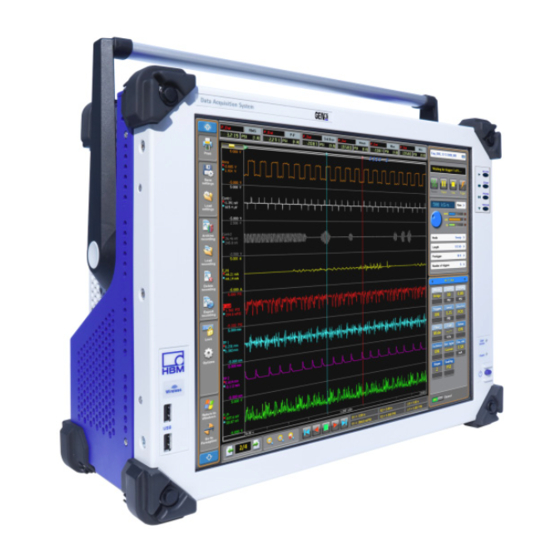
HBM GEN3i User Manual (1160 pages)
Portable Data Recorder
Brand:
HBM
| Category:
Data Loggers
| Size: 62.03 MB
Table of Contents
Table of Contents
5
About this Manual
19
Symbols Used in this Manual
19
Manual Conventions
20
Introduction
21
Safety Messages
21
FCC and General
24
Grounding
25
Instrument Symbols
27
Categories in Accordance with IEC 61010-2-030:2010
28
Basic Insulation Versus Reinforced
30
Measurement Categories
28
Protection and Isolation
28
Additional Means of Protection for Single Fault Conditions
31
Protection
32
Overvoltage/Current Protection
33
Isolation
33
Environment
34
Laser Safety
35
Manual Handling of Loads
36
International Safety Warnings
37
Operation of Electrical Installations
53
Normative Documents and Declarations
54
Electrical
54
Electrostatic Discharge (ESD)
54
Electro-Magnetic Compatibility (EMC)
55
Environment
58
Environmental Protection
58
CE Declaration of Conformity
59
FCC Class a Notice
60
Batteries
61
Packaging
58
WEEE - Waste Electrical and Electronic Equipment
58
General
61
Removal and Replacement
62
Remove/Replace the Battery from the Backplane
63
Remove/Replace the Battery from the PC Section
65
Recharging
68
Disposal
69
Mains Power
70
Power and Frequency Requirements
70
Connecting Power
71
Fuse Requirements and Protection
73
Fuse Replacement
74
Introducing Gen3I
76
Introduction
76
Mainframe Overview
78
Mainframe Feature Comparison
79
Hardware
81
PCI-E/Cpci Backplane
81
Input Cards
82
Master/Slave Support
82
Thermal Protection
82
Acquisition
84
Statstream
84
Signal Conditioning
86
Data Storage
87
PC Section
88
Perception Software
89
Windows Logon Password and Remote Desktop Access
91
Perception Language Settings
92
PC Connections
95
Setting up the Gen3I
95
DVI-I Graphics and Display Ports
96
USB 3.0 and USB 2.0 Ports
96
Sound, Microphone, Speakers
97
Removing and Installing Input Cards
98
Removing Cards
98
Installing Cards
99
Handle
101
Turning the Handle
102
Feet
105
To Turn the Feet out
105
To Turn the Feet in
105
Probe Calibration
106
DC Power Output
108
Digital Event/Timer/Counter
110
Isolated Event Adapter
114
Torque/Rpm Adapter
115
Getting Started
118
Front Panel Control
118
Getting Started
121
Wireless Network
122
Windows® 7: to Connect Gen3I to the Local Wireless Network
123
Windows® 7: to Disconnect Gen3I from the Local Wireless Network
124
Windows® 10: to Connect Gen3I to the Local Wireless Network
125
Windows® 10: to Disconnect Gen3I from the Local Wireless Network
129
Acquisition and Storage
131
Introduction
131
Recording
132
Storage
133
More on Sweeps
134
Pre-Trigger Sweeps
135
More on Continuous Data Storage
137
Real-Time Sampling and Time Base
139
Time Base
139
Time Base Settings for Ffts
140
Additional Information
142
10 Digital Trigger Modes
143
Introduction
143
Digital Trigger Detector
144
Understanding Digital Triggering
144
Valid Trigger Conditions
146
Trigger Modes
148
Basic Trigger Mode
148
Dual Trigger Mode
149
Window Trigger Mode
150
Dual-Window Trigger Mode
151
Sequential Trigger Mode
152
Trigger Qualifier
153
Trigger Add-Ons
154
Slope Detector
154
Pulse Detector
155
Hold off
156
Interval Timer
157
Interval Timer - Less
157
Interval Timer - more
158
Interval Timer - between
159
Interval Timer - Notbetween
160
Event Counter
161
Recorder and System Trigger
162
Channel Alarm
164
11 Interface/Controller
165
Introduction
165
Communication and Control
166
Network Protocols and Ports
167
Using the 1 Gbit Option Connections
168
Master/Slave Synchronization
169
Connecting Multiple Mainframes Using the Master/Slave Card
173
Connecting the Master/Slave Synchronization Connector
173
Setting the Master/Slave Operating Modes
176
Setting the Master/Slave Trigger
178
Synchronizing a Master/Slave Setup to External Time Sources
181
I/O Connector
182
I/O Connector Input Overvoltage Protection
183
I/O Connector Functions and Connector Pinning
184
Option - Optical 1 Gbit Ethernet Interface
188
Option - 10 Gbit Ethernet Interface
190
Installing a 1 Gbit SFP/10 Gbit SFP+ Module
197
Introduction
197
Warnings
197
Installation Steps
199
Option - IRIG and IRIG/GPS Time Synchronization
203
GPS Antenna System Rules
204
Rule 1: Antenna Placement
204
Rule 2: Is a GPS Line Amplifier Needed
205
Rule 3: Lightning Arrestors
205
Rule 4: Interconnect Cables
206
12 Input Cards
207
Available Input Cards
207
Acquisition Card Feature Comparison
210
Isolated 1Kv Input Cards
211
GN610B, Isolated 1Kv 2Ms/S Input Card with Real-Time Formula Database
211
GN611B, Isolated 1Kv 200Ks/S Input Card with Real-Time Formula Database
212
GN610, Isolated 1Kv 2Ms/S Input Card
213
GN611, Isolated 1 Kv 200Ks/S Input Card
214
Using the GN610/GN611 and GN610B/GN611B
215
Understanding the GN610/GN611 and GN610B/GN611B Category Rating
219
Understanding the GN610/GN611 and GN610B/GN611B Input
220
Using the High Precision Differential Probe
222
Measuring Currents
224
GN610/GN611, GN610B/GN611B Isolation and Type Testing
225
Channel to Chassis Isolation Test
227
Channel to Channel Isolation Test
229
High Potential Test
231
Engineering Tests
233
GN610/GN611 and GN610B/GN611B Input Overload Protection
234
GN610/GN611, GN610B/GN611B Protection Mechanisms
234
Overvoltage and Current Protection
234
Thermal Monitor of the Input Channels
236
Thermal Shutdown in Critical Conditions
237
Restore Range Selected by User Automatically
238
Isolated Basic/Iepe Cards
239
GN815, Isolated Basic/Iepe 2Ms/S Input Card
239
GN816, Isolated Basic/Iepe 200Ks/S Input Card
240
Using the GN815 and GN816
241
Understanding the GN815 and GN816 Isolation
243
Understanding the GN815 and GN816 Input
244
Characteristics Per Channel
245
Using Probes
245
GN815 and GN816 Input Overload Protection
246
Restore Range Selected by User Automatically
247
Thermal Monitor of the Input Channels
247
Thermal Shutdown in Critical Conditions
248
GN410 and GN411 Bridge Input Cards
249
Bridge Amplifier Configuration
249
Bridge Completion
251
Input Connectors
251
Shunt Calibration
251
Shielding and Driven Guard
252
Various Bridge Configurations
253
Bridge Connector Reference Card
256
Bridge Completion
257
Configuring and Using the Bridge Amplifier
257
Bridge Completion - Full (4/4) Bridge
258
Bridge Completion - Half (1/2 or 2/4) Bridge
259
Bridge Completion - Quarter (1/4) Bridge
261
Excitation
263
Shunt Verification - Setup
267
Shunt Verification - Procedure
269
Bridge Balance
271
GN440 and GN441 Universal Amplifier Input Cards
273
GN412 and GN413 High Speed - Differential Input Cards
274
High Resolution Universal Input Card
275
GN840/GN1640 Universal 500 Ks/S 8/16 Channel Input Cards
275
Basic Mode and Cabling
277
Supported Sensor Modes
277
Bridge Mode and Cabling
278
Basic Sensor and Cabling
280
Integrated Electronic Piezoelectric (IEPE) Mode and Cabling
281
Piezoelectric (Charge) Mode and Cabling
282
Resistive Temperature Detectors (RTD) Mode and Cabling
283
Current Loop Mode and Cabling
284
Thermocouple Mode and Cabling
285
DIN Rail Breakout
286
Flexible Wiring
289
High Resolution IEPE and Charge Input Cards
290
GN3210 IEPE and Charge 250 Ks/S Input Card
290
GN3211 Basic 20 Ks/S Input Card
291
GN401 Optical Fiber Isolated 100 Ms/S Input Card
293
Binary Marker Cards
294
GN6470 Binary Marker Card
294
GN4070 Binary Marker HV Card
295
Connector Pinning GN6470 and GN4070
296
GN6470 and GN4070 Input Block Diagram
297
GN6470 and GN4070 Counter Mode Pinning
298
GN6470 and GN4070 Frequency (RPM) Mode Pinning
299
GN6470 and GN4070 Quadrature (Position) Mode Pinning
300
Configure the Timer/Counters in Perception
302
To Activate Channel 8 or Channel 9 in Perception
302
GN4070 Connectors and Pinning
306
13 Option Cards
307
Option Carrier Card (OCC)
307
Option Cards Supported
308
Integration Card
309
14 GEN Series Synchronization Methods
316
Architecture
316
Ptp
316
PTP Technology Background(1)
316
PTP Protocol Details
317
Best Master Clock Algorithm (BMC)
318
PTP Switch Types
320
Switches Using Boundary Clocks
321
End-To-End Transparent Clocks
322
One-Step and Two-Step Clock Synchronization
322
Transparent Clock Switch Synchronization
324
Peer-To-Peer Transparent Clocks
322
Switches Using Transparent Clocks
322
Message-Based Synchronization
324
Switch Delays
327
Common Terms Used in IEEE
328
GEN Series Synchronization Methods Compared
330
Signal Phase Shift Synchronization
330
Trigger Synchronization
331
Absolute Time of Day Synchronization
333
Start/Stop Synchronization
334
Synchronization Specification Overview
336
15 Understanding Inputs and Usage of Probes
338
GEN Series Inputs
338
Single-Ended Input
339
Balanced Differential Input
341
Isolated Single-Ended or Isolated Unbalanced Differential Input
342
Isolated Balanced Differential Input
344
GEN Series Voltage Probe Types
346
Passive, Single-Ended Voltage Probes
347
Passive, Single-Ended Isolated Voltage Probes
350
High Accuracy Passive, Single-Ended Isolated Voltage Probes
352
Passive, Differential Matched Isolated Voltage Probes
354
Active Differential Voltage Probes
356
LDS Probe Part Number Reference Table
357
Probe Accessories
358
Probes Master List
359
Probe Bandwidth Calibration
360
Probes
360
Probes
362
Probes and Differential Measurements
363
Current Shunt Measurements
364
A Specifications
365
B3762-5.1 en (Gen3I Portable Data Recorder)
365
B2629-2.1 en (GEN Series GN401)
383
A.2 B2629–2.1 en (GEN Series GN401)
383
B2633-2.1 en (GEN Series GN410)
400
A.3 B2633–2.1 en (GEN Series GN410)
400
B2639-2.1 en (GEN Series GN411)
418
A.4 B2639–2.1 en (GEN Series GN411)
418
B2627-2.1 en (GEN Series GN412)
437
B4160-1.1 en (GEN Series GN413)
452
B2631-2.0 en (GEN Series GN440)
466
B2631-2.0 en (GEN Series GN441)
481
B3618-4.2 en (GEN Series GN610)
497
B4374-1.2 en (GEN Series GN610B)
520
B3716-4.2 en (GEN Series GN611)
549
B4375-1.1 en (GEN Series GN611B)
571
B3997-1.1 en (GEN Series GN815)
598
B3998-1.1 en (GEN Series GN816)
617
B4170-1.0 en (GEN Series GN840B, GN1640B)
635
B3240-3.1 en (GEN Series GN3210)
678
B3264-3.1 en (GEN Series GN3211)
703
B3246-1.0 en (GEN Series GN4070)
721
B3245-1.0 en (GEN Series GN6470)
725
B Options, to be Ordered Separately
728
Batteries and Battery Chargers
728
Rechargeable Li-Ion SM202 Battery
728
Li-Ion Battery Charger
729
Breakout Cables and Panels
730
Breakout Cables
730
Breakout Panels
732
B.2.2 Breakout Panels
732
DIN Rail Breakouts
733
Bridge Articles
735
Bridge Completion Pack
735
16 Pin LEMO Connector Pack
735
B.3 Bridge Articles
735
Burden Resistor
736
High Precision Burden Resistor
736
B.4 Burden Resistor
736
Card Adapters
737
Artificial Star Adapter
737
B.5 Card Adapters
737
Artifical Star Adapter Wiring Diagram
738
BNC to Banana Adapter
738
Option Carrier Card Extensions
739
Master Output Card
739
Option Carrier Card
741
IRIG and GPS Card
742
10Gbit Ethernet Card, Optical
744
10Gbit Ethernet Card, Electrical
745
Current Clamps
746
AC/DC Current Clamp I30S
746
B.7 Current Clamps
746
AC Current Clamp SR661
748
AC Current Clamp M1V-20-2
750
Current Transducers and Accessories
751
Current Transducers
751
Connection Cable LEM CT to MCTS
752
Power Supply for Current Transducer
753
Current Transducer (CT) Wire Diagram
754
Fiber Optic Cables and Sfps
755
Standard Fiber Optic Duplex Cable
755
Heavy Duty Fiber Optic Duplex Cable
755
Heavy Duty Fiber Optic Duplex Patch Cable
756
Standard Zipcord Fiber Optic Duplex Multi Mode Patch Cable
757
Standard Zipcord Fiber Optic Duplex Single Mode Patch Cable
758
Heavy Duty Fiber Optic Duplex Single Mode Cable
759
Gbit Optical Network SFP Module 850 Nm
760
Gbit Optical Network SFP Module 1310 Nm
760
Gbit Optical Network SFP Module 1310 Nm
761
Mainframe Adapters
762
B.10 Mainframe Adapters
762
G070A Torque/Rpm Adapter
762
G072 Isolated Digital Event Adapter
775
Isolated Digital Event Adapter to Marker Card Cable
785
Measurement Cables
786
B.11 Measurement Cables
786
Shielded 2 Wire 600 V RMS CAT II Cable
786
Test Leads and Clips
787
Rack Mount Kit
788
B.13 Shipping Case
789
Shipping Case
789
B.14 Software
790
Software
790
Voltage Probes
791
Free Viewer
790
Instrument Panel Languages
790
Perception Professional
790
Perception Standard Software
790
PNRF Free Viewer
790
B.15 Voltage Probes
791
Passive, Single-Ended Voltage Probes
791
Passive, Single-Ended Isolated Probes
796
Passive, Differential Matched Isolated Voltage Probes
797
Active, Differential Voltage Probe
800
High Precision Differential Probe
801
C Maintenance
803
Preventive Maintenance
803
Preventive Drive Replacement
804
Hard Disk Drive
804
Solid State Drive (SSD)
804
Cleaning
806
C.3 Cleaning
806
D Service Information
807
General - Service Information
807
Calibration/Verification
808
D.2 Calibration/Verification
808
E Trouble Shooting
809
Boot Setup
809
GHS Integrated System Image Restore
813
Boot Menu Preparation
813
Starting Image Restore
815
Image Restore Phase 1 - Installing Devices
818
Image Restore Phase 2 - Measuring Video Performance
818
Image Restore Phase 3 - Windows 7 Welcome
819
Image Restore Phase 3 - Windows 10 Welcome
829
Potential Problems after Restore
836
Touch Screen Calibration
839
WACOM Touch Screen
841
ELO Touch Screen
849
Backing up the Recovery Partition
853
Recovery Partition Creation
856
Using the Integrated System Recovery USB Disk
856
Starting Recovery Partition Creation
857
Starting Recovery Partition Restore
858
GHS Integrated System BIOS Update
861
Language Settings in Windows
863
How to Change the Windows 7 Display Language
863
How to Change the Windows 10 Display Language
864
Installing a Language Pack in Windows 7 Ultimate
868
Installing a Language Pack in Windows 10
871
Upgrading Gen3I and Gen7I to Windows 10
880
Enable the Windows 10 Upgrade on Gen3I/Gen7I
890
Embedded Software Upgrades
894
Boot Recovery Switch
894
Unexpected Mainframe Shutdown
897
The Master/Slave Connection Does Not Synchronize
898
The IRIG/GPS Does Not Synchronize
899
Optical Network (SFP)
900
Master/Slave Synchronization Verification Procedure
901
F Rack Mount Instructions
904
Mount Gen3I in a 19-Inch Rack
904
GPTP Synchronisation
906
Mainframe PTP Connections
906
Gen2I and Gen5I (no PTP Support)
906
Gen7T and Gen16T
906
Gen7I
907
G.1.3 Gen7I
907
Gen7Ta
908
G.1.4 Gen7Ta
908
Gen3I and Gen3T
909
Gen17Ta
910
G.1.6 Gen17Ta
910
Perception Settings
911
Gen7T/Gen16T - Perception Settings
911
G.2 Perception Settings
911
Gen3I, Gen7I, Gen3T, Gen7Ta and Gen17Ta - Perception Settings
912
Synchronizing GEN Series and Quantumx Using PTP
913
Gen3I/Gen7I with Single Quantumx "B" Version Module
913
Gen3I/Gen7I with Single Somatxr "B" Version Module
914
Gen3I/Gen7I with up to Three Quantumx "B" Version Modules
915
Background Network Details
915
G.3.4 Gen3I/Gen7I with Standard Network Switch and Four or more of Quantumx "B" Version Modules
916
Gen3I/Gen7I with PTP Network Switch and Four or more of Quantumx "B" Version Modules
918
Gen3T/Gen7Ta/Gen17Ta with Single Quantumx "B" Version Module
919
Gen7Ta with Multiple Quantumx "B" Version Modules
920
Gen7T/Gen16T with Single Quantumx "B" Version Module
921
Gen7T with Multiple Quantumx "B" Version Modules
922
Genesis and Quantumx Setup Using IRIG-To-PTP Bridge
923
G.3.11 PTP Grandmasters
924
GPS to PTP Bridge
924
IRIG or GPS to PTP Bridge
924
PTP Grandmasters
924
PTP Capable Switch
925
Using PTP and Master/Slave in Combined Setup
926
PTP Configuration Errors
927
H Application Specific Usage
928
Rotational External Clock
928
GEN DAQ Settings Explained
928
Memory and Time Base
930
Mainframe
930
Calculation Example
932
Perception Display Settings Explained
933
Cylinder Pressure Analysis Option Package
935
Cylinder Pressure Analysis Customer Evaluation
936
Cylinder Pressure Analysis and TDC Settings
936
Dy/Dt Triggering
937
H.2 Dy/Dt Triggering
937
External Start/Stop on Digital Event/Timer/Counter Connector
941
Calculating Maximum Fiber Cable Length
945
Wake on LAN Support (WOL)
947
Locating Gen3I and Gen7I Mac/Physical Address
949
Locating Gen3T, Gen7Ta and Gen17Ta Mac/Physical Address
951
Configuring an Encoder with Direction and Reset
953
From Encoder to Level Converter
953
From Level Converter to Digital I/O Connector on the Mainframe
956
Activate Digital I/O Channels with Perception
956
External Clock Divider
932
Calculating Sample Limits for External Time Base Use
932
Recorder/Time Base Groups
932
To Activate Channel 8 or Channel 9 in Perception
959
I Disk Storage Technology
965
Most Used RAID Modes
965
RAID 0 - Striping
967
I.1.1 RAID 0 – Striping
967
RAID 1 - Mirroring
968
I.1.2 RAID 1 – Mirroring
968
RAID 5 - Striping with Parity
969
I.1.3 RAID 5 – Striping with Parity
969
RAID Level 10 - Combining RAID 0 & RAID 1
970
Setting up the Iscsi Target Using Synology® NAS
971
JBE3200 USB to Optical RS232 Convertor
985
Re-Programming of the USB-RS232 (Opt. 650Nm) Converter to Work with BE3200
985
K Legacy Information - Input Cards
987
Basic Amplifier Non-Isolated Input Cards
987
GN810 Basic 200Ks/S Input Card
987
GN811 Basic 1Ms/S Input Card
988
GN812 Basic ISO 1Ms/S Input Card
989
Basic Extended Isolated Amplifier Card
990
GN813 Basic XT ISO 1 Ms/S Input Card
990
GN814 Basic XT ISO 200Ks/S Input Card
991
Optional G041 1Kv DC Probe
992
Optional G042 1Kv AC Probe
994
High Resolution IEPE and Charge Input Cards
997
GN1610 250 Ks/S Input Card
997
GN1611 Basic 20 Ks/S Input Card
999
Master/Slave Card (G040)
1001
Master/Slave Card Operations
1002
LED Indicators
1004
Installing and Removing the Master/Slave Card
1007
Connecting the Master/Slave Card
1015
Example of a Master/Slave Configuration (Legacy)
1016
Using Legacy and New Mainframes in Master/Slave Setup
1017
Connecting Multiple Mainframes Using the Master/Slave Card (Legacy)
1017
L Legacy Information - Specifications
1021
B2632-3.1 en (GEN Series GN810)
1021
B2640-3.1 en (GEN Series GN811)
1036
B2634-3.1 en (GEN Series GN812)
1051
B2635-4.1 en (GEN Series GN813)
1067
B2889-5.1 en (GEN Series GN814)
1083
B3240-3.1 en (GEN Series GN1610)
1098
B3264-3.1 en (GEN Series GN1611)
1122
M Rohs Compliance Overview
1142
GEN DAQ Mainframes - Restriction of Hazardous Substances Directive (Rohs) Status
1142
GEN DAQ Acquisition Cards - Restriction of Hazardous Substances Directive (Rohs) Status
1144
GEN DAQ Optical Cables - Restriction of Hazardous Substances Directive (Rohs) Status
1146
GEN DAQ Probes - Restriction of Hazardous Substances Directive (Rohs) Status
1147
GEN DAQ Current Clamps - Restriction of Hazardous Substances Directive (Rohs) Status
1148
Advertisement
Advertisement
Related Products
HBM Genesis series
HBM GEN series
HBM GN610
HBM GN611
HBM GK7000
HBM GK7600
HBM Genesis GEN5i
HBM Operating Manual
HBM PMX
HBM SOMAT XR CX22B-R
HBM Categories
Transducer
Measuring Instruments
Accessories
Amplifier
Industrial Equipment
More HBM Manuals
Login
Sign In
OR
Sign in with Facebook
Sign in with Google
Upload manual
Upload from disk
Upload from URL