Sun Microsystems Sun Blade 1000 Service Manual
Hide thumbs
Also See for Sun Blade 1000:
- Manual (22 pages) ,
- Module installation manual (36 pages) ,
- Cpu module installation instructions (36 pages)
Table of Contents
Troubleshooting

Related Manuals for Sun Microsystems Sun Blade 1000


Summary of Contents for Sun Microsystems Sun Blade 1000
- Page 1 Sun Blade™ 1000 and SunBlade 2000 Service Manual Sun Microsystems, Inc. 4150 Network Circle Santa Clara, CA 95054 U.S.A. 650-960-1300 Part No. 816-3217-10 January 2002, Revision A Send comments about this document to: docfeedback@sun.com...
- Page 2 The OPEN LOOK and Sun™ Graphical User Interface was developed by Sun Microsystems, Inc. for its users and licensees. Sun acknowledges the pioneering efforts of Xerox in researching and developing the concept of visual or graphical user interfaces for the computer industry. Sun holds a non-exclusive license from Xerox to the Xerox Graphical User Interface, which license also covers Sun’s licensees who implement OPEN LOOK...
-
Page 3: Table Of Contents
Contents Preface xxxv Product Description 1-1 Product Overview 1-1 1.1.1 External Components 1-4 Replaceable Components 1-8 SunVTS Overview 2-1 SunVTS Description 2-1 2.1.1 SunVTS Requirements 2-2 2.1.2 SunVTS References 2-2 Power On Self-Test 3-1 POST Overview 3-1 3.1.1 How to Use POST 3-2 Pre-POST Preparation 3-2 3.2.1 Setting Up a TIP Connection 3-2... - Page 4 Output Message 4-18 4.9.5 ebus@5 Output Message 4-18 4.9.6 firewire@5,2 Output Message 4-19 4.9.7 flashprom@0,0 Output Message 4-19 4.9.8 Floppy Output Message 4-19 4.9.9 gpio@1,300600 Output Message 4-20 Sun Blade 1000 and Sun Blade 2000 Service Manual • January 2002...
- Page 5 4.9.10 i2c@1,2e Output Message 4-20 4.9.11 i2c@1,30 Output Message 4-21 4.9.12 network@5,1 Output Message 4-21 4.9.13 Parallel Port Output Message 4-21 4.9.14 pmc@1,300700 Output Message 4-22 4.9.15 rtc@1,300070 Output Message 4-22 4.9.16 scsi@6 Output Message 4-22 4.9.17 scsi@6,1 Output Message 4-23 4.9.18 Serial Output Message 4-23 4.9.19...
- Page 6 Fan Bracket 6-23 6.6.1 Removing the Fan Bracket 6-23 6.6.2 Replacing the Fan Bracket 6-24 Speaker Assembly 6-25 6.7.1 Removing the Speaker Assembly 6-25 6.7.2 Replacing the Speaker Assembly 6-26 Sun Blade 1000 and Sun Blade 2000 Service Manual • January 2002...
- Page 7 FC-AL Backplane Assembly 6-27 6.8.1 Removing the FC-AL Backplane Assembly 6-27 6.8.2 Replacing the FC-AL Backplane Assembly 6-28 Chassis Foot 6-29 6.9.1 Removing a Chassis Foot 6-29 6.9.2 Replacing a Chassis Foot 6-30 6.10 Filler Panels 6-31 6.10.1 Removing a Filler Panel 6-31 6.10.2 Replacing a Filler Panel 6-32 Removing and Replacing Storage Devices 7-1...
- Page 8 Replaceable Battery 8-34 8.7.1 Removing the Battery 8-34 8.7.2 Replacing the Battery 8-34 Motherboard 8-35 8.8.1 Removing the Motherboard 8-36 8.8.2 Replacing the Motherboard 8-38 CPU Shroud 8-40 viii Sun Blade 1000 and Sun Blade 2000 Service Manual • January 2002...
- Page 9 8.9.1 Removing the CPU Shroud 8-40 8.9.2 Replacing the CPU Shroud 8-41 Finishing Replacement Procedures 9-1 Replacing the Access Panel 9-1 Powering On the Workstation 9-4 Enabling Power Management 9-5 9.3.1 Activating the Workstation From Low-Power Mode 9-6 Disabling Power Management 9-7 OpenBoot Emergency Procedures 10-1 10.1 OpenBoot Emergency Procedures for Workstations With Standard (Non-...
- Page 10 System Requirements for the UltraSPARC III 900 MHz CPU Module C-8 C.1.2.5 System Requirements for the UltraSPARC III Cu CPU Module C-9 C.1.3 System Memory C-9 C.1.3.1 Organization C-9 C.1.3.2 Memory Configuration C-12 Sun Blade 1000 and Sun Blade 2000 Service Manual • January 2002...
- Page 11 C.1.3.3 Memory Modules C-13 C.1.3.4 Memory Module Configuration Rules C-13 C.1.3.5 System Memory Interleaving C-14 C.1.3.6 Memory Timing C-16 C.1.4 I/O Subsystem C-17 C.1.4.1 SBC ASIC C-17 C.1.4.2 PCIO-2 C-20 C.1.4.3 EBus Leaf C-22 C.1.5 Interrupts C-22 C.1.6 BootBus C-23 C.1.6.1 BootBus Controller (BBC) ASIC C-24 C.1.7...
- Page 12 Motherboard C-44 Jumper Descriptions C-47 C.4.1 Flash PROM Jumpers C-48 Enclosure C-50 C.5.1 Enclosure Basics C-50 C.5.2 Enclosure Features C-50 Power Management C-51 C.6.1 Subsystems Power Management C-52 Sun Blade 1000 and Sun Blade 2000 Service Manual • January 2002...
- Page 13 C.6.1.1 UltraSPARC III Processor(s), Main Memory, and Sun CrossBar Interconnect C-52 C.6.1.2 EPCI Bus C-52 C.6.1.3 Storage Devices C-52 C.6.1.4 Audio C-53 C.6.1.5 IEEE 1394 Bus C-53 C.6.1.6 USB C-53 D. USB Support D-1 USB Keyboard and Mouse D-1 D.1.1 USB Keyboard D-1 D.1.2 USB Mouse D-2...
- Page 14 Sun Blade 1000 and Sun Blade 2000 Service Manual • January 2002...
- Page 15 Figures Sun Blade 1000 and Sun Blade 2000 Workstation, Monitor, Keyboard, and Mouse 1-4 FIGURE 1-1 Front Panel Overview — Sun Blade 1000 and Sun Blade 2000 Workstations 1-5 FIGURE 1-2 Back Panel Overview — Sun Blade 1000 and Sun Blade 2000 Workstations 1-6 FIGURE 1-3 Exploded View —...
- Page 16 Torque Tool A Clicks When the Captive Screws Are Correctly Torqued 8-19 FIGURE 8-14 Removing and Replacing a PCI Card 8-21 FIGURE 8-15 Graphics, EPCI, and PCI Card Slots 8-24 FIGURE 8-16 Sun Blade 1000 and Sun Blade 2000 Service Manual • January 2002...
- Page 17 Diskette Drive Connector J1801 B-21 FIGURE B-17 Internal SCSI Connector J5002 B-24 FIGURE B-18 Internal FC-AL Connector J2901 B-25 FIGURE B-19 Logo LED Connector J3605 B-26 FIGURE B-20 Sun Blade 1000 and Sun Blade 2000 Functional Block Diagram C-3 FIGURE C-1 Figures xvii...
- Page 18 FIGURE C-14 System Motherboard Block Diagram C-45 FIGURE C-15 Selected Jumper Settings C-47 FIGURE C-16 Identifying Jumper Pins C-48 FIGURE C-17 Flash PROM Jumper Locations C-49 FIGURE C-18 xviii Sun Blade 1000 and Sun Blade 2000 Service Manual • January 2002...
- Page 19 Tables Sun Blade 1000 and Sun Blade 2000 Product Features and Options 1-2 TABLE 1-1 Back Panel Overview — Sun Blade 1000 and Sun Blade 2000 Workstations 1-7 TABLE 1-2 Replaceable Components 1-10 TABLE 1-3 Approximate POST Completion Times 3-5...
- Page 20 Audio Card Features C-37 TABLE C-6 ISP2200A GPIO Bits C-39 TABLE C-7 Power Supply Output Values for the Sun Blade 1000 and Sun Blade 2000 C-43 TABLE C-8 Power Supply Control Signal Levels C-43 TABLE C-9 Motherboard Component Functions C-46...
- Page 21 FCC radio frequency emission limits. Networking connections can be made using unshielded twisted-pair (UTP) cables. Modifications: Any modifications made to this device that are not approved by Sun Microsystems, Inc. may void the authority granted to the user by the FCC to operate this equipment.
- Page 22 ICES-003 Class B Notice - Avis NMB-003, Classe B This Class B digital apparatus complies with Canadian ICES-003. Cet appareil numérique de la classe B est conforme à la norme NMB-003 du Canada. xxii Sun Blade 1000 and Sun Blade 2000 Service Manual • January 2002...
- Page 23 BSMI Class A Notice The following statement is applicable to products shipped to Taiwan and marked as Class A on the product compliance label. Regulatory Compliance Statements xxiii...
- Page 24 Sun Blade 1000 and Sun Blade 2000 Service Manual • January 2002...
- Page 25 Declaration of Conformity Compliance Model Number: Product Family Name: Sun Blade 1000 and Sun Blade 2000 USA—FCC Class B This equipment complies with Part 15 of the FCC Rules. Operation is subject to the following two conditions: 1. This equipment may not cause harmful interference.
- Page 26 Sun Blade 1000 and Sun Blade 2000 Service Manual • January 2002...
- Page 27 Modifications to Equipment reduce the risk of electric shock, always plug Do not make mechanical or electrical modifications to the the cord into a grounded power outlet equipment. Sun Microsystems is not responsible for regulatory compliance of a modified Sun product. xxvii...
- Page 28 Ne pas apporter de modification mécanique ou électrique radiation exposure. au matériel. Sun Microsystems n’est pas responsable de la conformité réglementaire d’un produit Sun qui a été modifié. xxviii Sun Blade 1000 and Sun Blade 2000 Service Manual • January 2002...
- Page 29 Positionnement d’un produit Sun Attention – votre produit Sun a été livré équipé d’un cordon d’alimentation à trois fils Attention – pour assurer le bon (avec prise de terre). Pour écarter tout risque fonctionnement de votre produit Sun et pour d’électrocution, branchez toujours ce cordon l’empêcher de surchauffer, il convient de ne dans une prise mise à...
- Page 30 Netzsteckdosen geliefert. Um die Gefahr eines Stromschlags zu reduzieren, schließen Sie das Kabel nur an eine fachgerecht verlegte, geerdete Steckdose an. Achtung – Gefährliche Spannungen. Anweisungen befolgen, um Stromschläge und Verletzungen zu vermeiden Sun Blade 1000 and Sun Blade 2000 Service Manual • January 2002...
- Page 31 Modificaciones en el equipo No realice modificaciones de tipo mecánico o eléctrico en el CD-ROM oder DVD-ROM equipo. Sun Microsystems no se hace responsable del cumplimiento de las normativas de seguridad en los equipos Sun modificados. Achtung – Die Verwendung von anderen...
- Page 32 No utilice alargadores de tipo doméstico para conectar Class 1 Laser Product sus productos Sun. Luokan 1 Laserlaite Klasse 1 Laser Apparat Laser KLasse 1 xxxii Sun Blade 1000 and Sun Blade 2000 Service Manual • January 2002...
- Page 33 CD-ROM Suomi Precaución – El manejo de los controles, los VAROITUS – Paristo voi räjähtää, jos se on ajustes o la ejecución de procedimientos virheellisesti asennettu. Vaihda paristo distintos a los aquí especificados pueden ainoastaan laitevalmistajan suosittelemaan exponer al usuario a radiaciones peligrosas. tyyppiin.
- Page 34 Sun Blade 1000 and Sun Blade 2000 Service Manual • January 2002...
-
Page 35: Preface
Preface The Sun Blade 1000 and Sun Blade 2000 Service Manual provides a detailed description of the hardware components used in the Sun Blade™ 1000 and Sun Blade 2000 workstations. This service manual includes information about the use, maintenance, troubleshooting, theory of operation, and product specifications for the workstations. - Page 36 Sun Blade 1000 and Sun Blade 2000 workstations. Appendix D describes the interaction of the USB mouse, USB keyboard, and USB power management with the Sun Blade 1000 and Sun Blade 2000 workstations. xxxvi Sun Blade 1000 and Sun Blade 2000 Service Manual • January 2002...
- Page 37 UNIX Commands ® This document may not contain information on basic UNIX commands and procedures such as shutting down the workstation, booting the workstation, and configuring devices. See one or more of the following for this information: Solaris Handbook for Sun Peripherals AnswerBook2™...
- Page 38 12-24 Gbyte 4-mm DDS-3 Tape Drive Installation and User’s Guide 802-7791 Installation Sun Blade 1000 and Sun Blade 2000 Rackmount Installation Guide 805-7959 Installation/user Sun StorEdge CD32 Installation and User’s Guide 805-4237 xxxviii Sun Blade 1000 and Sun Blade 2000 Service Manual • January 2002...
- Page 39 Application Title Part Number Specification Manual Eject Diskette Drive Specifications 805-1133 Specification 18 GB 10K rpm Disk Drive Specifications 806-1057 Specification 36 GB 10K rpm Disk Drive Specifications 806-4799 Specification 73 GB 10K rpm Disk Drive Specifications 816-1133 Specification 8-mm Tape Drive Specifications 802-5775 Specification 4-mm, DDS-2 Tape Drive Specifications...
- Page 40 Sun Blade 1000 and Sun Blade 2000 Service Manual • January 2002...
-
Page 41: Product Description
C H A P T E R Product Description This chapter contains an overview of the Sun Blade 1000 and Sun Blade 2000 workstations. This product description includes a product overview and a list of replaceable components for the workstation. -
Page 42: Table 1-1 Sun Blade 1000 And Sun Blade 2000 Product Features And Options
Sun Blade 1000 and Sun Blade TABLE 1-1 2000 standard features and options. Sun Blade 1000 and Sun Blade 2000 Product Features and Options TABLE 1-1 Sun Blade 1000 Sun Blade 2000... - Page 43 Refresh rates from 60 Hz to 112 Hz. 1. First version of the Solaris operating environment that supports the Sun Blade 1000 or Sun Blade 2000 workstations. Always check the Sun web site for the latest compatible operating environment, firmware,...
-
Page 44: External Components
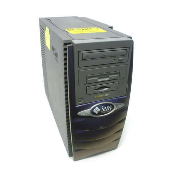
Sun Blade 1000 and Sun Blade 2000 workstations. Monitor Workstation Mouse Keyboard Sun Blade 1000 and Sun Blade 2000 Workstatio n, Monitor, Keyboard, and FIGURE 1-1 Mouse Sun Blade 1000 and Sun Blade 2000 Service Manual • January 2002... -
Page 45: Figure 1-2 Front Panel Overview - Sun Blade 1000 And Sun Blade 2000 Workstations
Front Panel Overview — Sun Blade 1000 and Sun Blade 2000 Workstations FIGURE 1-2 1. Peripheral bezel 2. 5.25-inch drive bay (optional DVD-ROM drive shown) 3. 5.25- or 3.5-inch drive bay (optional diskette drive shown) 4. Smart card reader 5. Power switch 6. -
Page 46: Figure 1-3 Back Panel Overview - Sun Blade 1000 And Sun Blade 2000 Workstations
Back Panel Overview — Sun Blade 1000 and Sun Blade 2000 Workstations FIGURE 1-3 Sun Blade 1000 and Sun Blade 2000 Service Manual • January 2002... -
Page 47: Table 1-2 Back Panel Overview - Sun Blade 1000 And Sun Blade 2000 Workstations
Back Panel Overview — Sun Blade 1000 and Sun Blade 2000 Workstations TABLE 1-2 Callout in Figure 1-3 Explanation Back Panel Symbol None Access panel lock block Serial connectors A and B, DB-25 (can support RS-423 and RS-232 protocols) SCSI connector (UltraSCSI, 68-pin) -
Page 48: Replaceable Components
PCI 1 PCI card slot 1 (66 MHz) Power connector None Replaceable Components This section lists the authorized replaceable parts for the Sun Blade 1000 and Sun Blade 2000 workstations. lists the replaceable components for both TABLE 1-3 systems. is an exploded view of each of the listed components in... -
Page 49: Figure 1-4 Exploded View - Sun Blade 1000 And Sun Blade 2000 Workstations
Exploded View — Sun Blade 1000 and Sun Blade 2000 Workstations FIGURE 1-4 Chapter 1 Product Description... -
Page 50: Table 1-3 Replaceable Components
Internal SCSI cable for removable bay Peripheral power cable DC power cable assembly assembly Diskette drive cable Diskette drive cable assembly assembly Smart card cable 20 inch, 10-pin, I2C cable 1-10 Sun Blade 1000 and Sun Blade 2000 Service Manual • January 2002... - Page 51 Replaceable Components (Continued) TABLE 1-3 Ref. No. Component Description Motherboard assembly System board Power supply assembly Power supply, 670 watts DVD-ROM drive DVD-ROM drive Manual eject floppy Diskette drive assembly Smart card reader Smart card reader assembly Speaker assembly 16 ohm speaker FC-AL backplane Provides interface between hard drive(s) and assembly...
- Page 52 1-12 Sun Blade 1000 and Sun Blade 2000 Service Manual • January 2002...
-
Page 53: Sunvts Overview
C H A P T E R SunVTS Overview This chapter contains an overview of the SunVTS diagnostic tool. The SunVTS diagnostic tool should be used to validate workstation operation during development, production, inspection, troubleshooting, periodic maintenance, and subsystem stressing. This chapter contains the following topics: Section 2.1, “SunVTS Description”... -
Page 54: Sunvts Requirements
SunVTS Quick Reference Card provides an overview of how to use the SunVTS CDE interface. SunVTS Test Reference Manual provides details about each individual SunVTS test. Sun Blade 1000 and Sun Blade 2000 Service Manual • January 2002... -
Page 55: Power On Self-Test
C H A P T E R Power On Self-Test This chapter describes how to initiate power on self-test (POST) diagnostics. POST is a firmware program used to determine workstation failures. POST verifies the core functionality of the workstation, including operation of the CPU module(s), motherboard, memory, and some on-board I/O devices. -
Page 56: How To Use Post
1. Connect serial port A of the workstation being tested to serial port B of another Sun system using a serial null modem cable (connect cable pins 2-3, 3-2, 7-20, and 20-7). Sun Blade 1000 and Sun Blade 2000 Service Manual • January 2002... -
Page 57: Figure 3-1 Setting Up A Tip Connection
Setting Up a TIP Connection FIGURE 3-1 2. At the other Sun system, check the /etc/remote file by changing to the /etc directory and then editing the remote file: hardwire:\ :dv=/dev/term/b:br#9600:el=^C^S^Q^U^D:ie=%$:oe=^D: Note – The example shows connection to serial port B of the other Sun system. 3. -
Page 58: Verifying The Baud Rate
Note – The default setting is min. See Section 3.4, “Maximum and Minimum Levels of POST” on page 3-5 below to set POST to the min mode. To set the diag-switch? to true: Sun Blade 1000 and Sun Blade 2000 Service Manual • January 2002... -
Page 59: Maximum And Minimum Levels Of Post
1. At the system prompt, type: ok setenv diag-switch? true ok setenv diag-level = min, max, menus Note – At the system prompt, type: ok setenv diag-level = “min” or “max” or “menus” Do not type “min”, “max” and “menus”. 2. -
Page 60: Diag-Level Variable Set To Max
— diag-level variable set to max (single CPU) CODE EXAMPLE 3-2 Note – The following POST examples are executed with 750 MHz CPUs and 512 MB of memory. Sun Blade 1000 and Sun Blade 2000 Service Manual • January 2002... - Page 61 diag-level Variable Set to max (2-Way CPU) (1 of 15) CODE EXAMPLE 3-1 @(#) 4.0 Version 28 created 2000/06/27 18:05 Clearing TLBs Done Power-On Reset Executing Power On SelfTest {0}@(#)POST, v4.1.1 06/30/2000 02:15 PM {0}* Test CPU present {1}@(#)POST, v4.1.1 06/30/2000 02:15 PM {1}* Test CPU present {0}Soft POR to the whole system {1}Soft POR to the whole system...
- Page 62 {1}Walk 1/0 STICK Compare register {0}* Stick & Stick-Compare Reg {1}Verify STICK register is counting {0}Walk 1/0 STICK Compare register {1}Verify STICK register Overflow {0}Verify STICK register is counting {1}Verify STICK Interrupt Sun Blade 1000 and Sun Blade 2000 Service Manual • January 2002...
- Page 63 diag-level Variable Set to max (2-Way CPU) (3 of 15) CODE EXAMPLE 3-1 {0}Verify STICK register Overflow {0}Verify STICK Interrupt {1}* Measure CPU Clock {0}* Measure CPU Clock {0}AFT pin is high {0}Setup Memory Controller {0}* IMMU Registers {1}* IMMU Registers {0}Testing I-TSB {1}Testing I-TSB {0}Test walking 1 through the register...
- Page 64 {0}* 8K DTLB TAG {1}Test data reliability {0}Test address up {1}Test address line transitions {1}* 8K DTLB TAG {1}Test address up {0}Test address down {1}Test address down 3-10 Sun Blade 1000 and Sun Blade 2000 Service Manual • January 2002...
- Page 65 diag-level Variable Set to max (2-Way CPU) (5 of 15) CODE EXAMPLE 3-1 {0}Test address line transitions {1}Test address line transitions {0}* 4M ITLB RAM {0}Test address up {0}Test address down {0}Test cell disturbance {1}* 4M ITLB RAM {0}Test data reliability {1}Test address up {1}Test address down {0}Test address line transitions...
- Page 66 {1}* I-Cache RAM {0}Test address up {1}Test address up {0}Test address down {1}Test address down {0}Test cell disturbance {1}Test cell disturbance {0}Test data reliability {1}Test data reliability 3-12 Sun Blade 1000 and Sun Blade 2000 Service Manual • January 2002...
- Page 67 diag-level Variable Set to max (2-Way CPU) (7 of 15) CODE EXAMPLE 3-1 {0}Test address line transitions {1}Test address line transitions {0}* I-Cache TAGS {0}Testing I-Cache Tag {0}Test address up {1}* I-Cache TAGS {1}Testing I-Cache Tag {1}Test address up {0}Test address down {1}Test address down {0}Test cell disturbance {1}Test cell disturbance...
- Page 68 {0}Test address up {1}* D-Cache SnoopTags {1}Test address up {0}Test address down {1}Test address down {0}Test cell disturbance {1}Test cell disturbance {0}Test data reliability {1}Test data reliability 3-14 Sun Blade 1000 and Sun Blade 2000 Service Manual • January 2002...
- Page 69 diag-level Variable Set to max (2-Way CPU) (9 of 15) CODE EXAMPLE 3-1 {0}Test address line transitions {1}Test address line transitions {0}* D-Cache Init {1}* D-Cache Init {0}* W-Cache RAM {0}Test address up {0}Test address down {0}Test cell disturbance {0}Test data reliability {1}* W-Cache RAM {1}Test address up {1}Test address down...
- Page 70 {1}Test address down {0}Test walking 1/0 FPU registers {1}Test cell disturbance {1}Test data reliability {1}Test address line transitions {1}* P-Cache Status Data {1}Test address up {1}Test address down 3-16 Sun Blade 1000 and Sun Blade 2000 Service Manual • January 2002...
- Page 71 diag-level Variable Set to max (2-Way CPU) (11 of 15) CODE EXAMPLE 3-1 {1}Test cell disturbance {1}Test data reliability {1}Test address line transitions {1}* P-Cache Init {1}* FPU Registers {1}Test walking 1/0 FPU registers {0}Test register addressing {0}* FSR {0}Test walking 1 FSR register {0}* Ecache RAM {0}Test address up {1}Test register addressing...
- Page 72 {0}memtst sbuf addr port A {1}memtst pg addr port B {1}memtst sbuf addr port B {0}* Schizo merg test {0}merg_wr 8 byte port A {0}merg_wr 4 byte port A 3-18 Sun Blade 1000 and Sun Blade 2000 Service Manual • January 2002...
- Page 73 diag-level Variable Set to max (2-Way CPU) (13 of 15) CODE EXAMPLE 3-1 {0}merg_wr 2 byte port A {1}* Schizo merg test {0}merg_wr 1 byte port A {1}merg_wr 8 byte port B {0}merg_blkwr block port A {1}merg_wr 4 byte port B {1}merg_wr 2 byte port B {1}merg_wr 1 byte port B {1}merg_blkwr block...
- Page 74 {0}* FPU Branch {0}Testing Branching on fcc0 {0}Verify branching {0}Verify no branching {0}Testing Branching on fcc1 {0}Verify branching {0}Verify no branching {0}Testing brancing on fcc2 {0}Verify branching 3-20 Sun Blade 1000 and Sun Blade 2000 Service Manual • January 2002...
- Page 75 diag-level Variable Set to max (2-Way CPU) (15 of 15) CODE EXAMPLE 3-1 {0}Verify no branching {0}Testing Branching on fcc3 {0}Verify branching {0}Verify no branching {0}* Ecache Functional {0}Verify cacheline fill on read miss {0}Verify write allocate on write miss {0}Verify cacheline update on write hit {0}Verify write back {0}* Xcall Test...
- Page 76 {0}DIMM 1: {0}DIMM 2: {0}DIMM 3: {0}DIMM 4: {0}DIMM 5: {0}DIMM 6: {0}DIMM 7: {0}Bank 0 not present, size = 00000000.00000000 {0}Bank 1 is present, size = 00000000.10000000 3-22 Sun Blade 1000 and Sun Blade 2000 Service Manual • January 2002...
- Page 77 diag-level Variable Set to max (single CPU) (2 of 9) CODE EXAMPLE 3-2 {0}Bank 2 not present, size = 00000000.00000000 {0}Bank 3 not present, size = 00000000.10000000 {0}* Setup CPUs and system frequency {0}CPU 0 ratio: 4 {0}CPU 1 ratio: 0 {0}System frequency: 150 MHz {0}* Load PLL and reset {0}PLL reset...
- Page 78 {0}Test address line transitions {0}* 4M ITLB TAG {0}Test address up {0}Test address down {0}Test cell disturbance {0}Test data reliability {0}Test address line transitions {0}* 8K ITLB TAG 3-24 Sun Blade 1000 and Sun Blade 2000 Service Manual • January 2002...
- Page 79 diag-level Variable Set to max (single CPU) (4 of 9) CODE EXAMPLE 3-2 {0}Test address up {0}Test address down {0}Test address line transitions {0}* IMMU Init {0}* DMMU Init {0}Mapping done. MMU enabled {0}* Memory address selection Initial area {0}* Memory marching Initial area {0}* E-Cache Global Vars Init {0}* E-Cache Quick Verification {0}* Ecache TAGS...
- Page 80 {0}Test data reliability {0}Test address line transitions {0}* W-Cache SnoopTAGS {0}Test address up {0}Test address down {0}Test cell disturbance {0}Test data reliability {0}Test address line transitions {0}* W-Cache Init 3-26 Sun Blade 1000 and Sun Blade 2000 Service Manual • January 2002...
- Page 81 diag-level Variable Set to max (single CPU) (6 of 9) CODE EXAMPLE 3-2 {0}* P-Cache RAM {0}Test address up {0}Test address down {0}Test cell disturbance {0}Test data reliability {0}Test address line transitions {0}* P-Cache TAGS {0}Test address up {0}Test address down {0}Test cell disturbance {0}Test data reliability {0}Test address line transitions...
- Page 82 {0}PCI B Device ID 8001 {0}* Schizo mem test {0}memtst ram data port B {0}memtst cam data port B {0}memtst ram addr port B {0}memtst cam addr port B 3-28 Sun Blade 1000 and Sun Blade 2000 Service Manual • January 2002...
- Page 83 diag-level Variable Set to max (single CPU) (8 of 9) CODE EXAMPLE 3-2 {0}memtst pnta port B {0}memtst lnta port B {0}memtst rnta port B {0}memtst enta port B {0}memtst ln addr port B {0}memtst pg addr port B {0}memtst sbuf addr port B {0}* Schizo merg test {0}merg_wr 8 byte port B {0}merg_wr 4 byte port B...
-
Page 84: Diag-Level Variable Set To Min
2-way, and single CPU configurations. diag-level Variable Set to min (2-Way CPU)— CODE EXAMPLE 3-3 diag-level Variable Set to min (single CPU) — CODE EXAMPLE 3-4 3-30 Sun Blade 1000 and Sun Blade 2000 Service Manual • January 2002... - Page 85 diag-level Variable Set to min (2-Way CPU) (1 of 12) CODE EXAMPLE 3-3 @(#) 4.0 Version 28 created 2000/06/27 18:05 Clearing TLBs Done Power-On Reset Executing Power On SelfTest {0}@(#)POST, v4.1.1 06/30/2000 02:15 PM {0}* Test CPU present {1}@(#)POST, v4.1.1 06/30/2000 02:15 PM {1}* Test CPU present {0}Soft POR to the whole system {1}Soft POR to the whole system...
- Page 86 {0}Verify TICK register is counting {1}Verify TICK Interrupt {0}Verify TICK register Overflow {0}Verify TICK Interrupt {1}* Stick & Stick-Compare Reg {1}Walk 1/0 STICK Compare register {0}* Stick & Stick-Compare Reg 3-32 Sun Blade 1000 and Sun Blade 2000 Service Manual • January 2002...
- Page 87 diag-level Variable Set to min (2-Way CPU) (3 of 12) CODE EXAMPLE 3-3 {0}Walk 1/0 STICK Compare register {1}Verify STICK register Overflow {0}Verify STICK register is counting {1}Verify STICK Interrupt {0}Verify STICK register Overflow {0}Verify STICK Interrupt {1}* Measure CPU Clock {0}* Measure CPU Clock {0}AFT pin is high {0}Setup Memory Controller...
- Page 88 {1}Test address line transitions {0}* 4M ITLB RAM {0}Test address up {0}Test address down {1}* 4M ITLB RAM {0}Test cell disturbance {0}* 8K ITLB RAM {1}Test address down 3-34 Sun Blade 1000 and Sun Blade 2000 Service Manual • January 2002...
- Page 89 diag-level Variable Set to min (2-Way CPU) (5 of 12) CODE EXAMPLE 3-3 {0}Test address up {1}Test cell disturbance {0}Test address down {1}* 8K ITLB RAM {1}Test address up {0}Test cell disturbance {1}Test address down {1}Test cell disturbance {0}* 4M ITLB TAG {0}Test address up {0}Test address down {0}Test cell disturbance...
- Page 90 {1}Test address down {0}Test cell disturbance {1}Test cell disturbance {0}* I-Cache Init {1}* I-Cache Init {0}* D-Cache RAM {0}Test address up {1}* D-Cache RAM {1}Test address up 3-36 Sun Blade 1000 and Sun Blade 2000 Service Manual • January 2002...
- Page 91 diag-level Variable Set to min (2-Way CPU) (7 of 12) CODE EXAMPLE 3-3 {0}Test address down {1}Test address down {0}Test cell disturbance {1}Test cell disturbance {0}* D-Cache TAGS {0}Test address up {1}* D-Cache TAGS {1}Test address up {0}Test address down {1}Test address down {0}Test cell disturbance {1}Test cell disturbance...
- Page 92 {0}* P-Cache Init {1}Test address down {0}* FPU Registers {1}Test cell disturbance {0}Test walking 1/0 FPU registers {1}* P-Cache Status Data {1}Test address up {1}Test address down 3-38 Sun Blade 1000 and Sun Blade 2000 Service Manual • January 2002...
- Page 93 diag-level Variable Set to min (2-Way CPU) (9 of 12) CODE EXAMPLE 3-3 {1}Test cell disturbance {1}* P-Cache Init {1}* FPU Registers {1}Test walking 1/0 FPU registers {0}Test register addressing {0}* FSR {0}Test walking 1 FSR register {0}* Ecache RAM {1}Test register addressing {0}Test address up {1}* FSR...
- Page 94 {0}merg_wr 4 byte port A {1}* Schizo merg test {1}merg_wr 8 byte port B {1}merg_wr 4 byte port B {0}* Map PCI B space for RIO {0}* RIO Config 3-40 Sun Blade 1000 and Sun Blade 2000 Service Manual • January 2002...
- Page 95 diag-level Variable Set to min (2-Way CPU) (11 of 12) CODE EXAMPLE 3-3 {0}* RIO EBus access {1}* Icache Functional {1}Verify cacheline fill on read miss {1}* Dcache Functional {1}Verify no allocate on write miss {1}Verify fetch from memory on read miss {1}Verify write-through on write hit {1}Verify write-through/fetch on read miss {1}Verify set-associativity...
- Page 96 {0}* Xcall Test {0}Sending Cross Calls to CPU AID 1 {1}POST_END Note – The following POST examples are executed with 750-MHz CPUs and 512- MB of memory. 3-42 Sun Blade 1000 and Sun Blade 2000 Service Manual • January 2002...
- Page 97 diag-level Variable Set to min (Single CPU) (1 of 8) CODE EXAMPLE 3-4 @(#) 4.0 Version 35 created 2000/01/21 17:29 Clearing TLBs Done Executing Power On SelfTest @(#) 4.0 Version 28 created 2000/06/27 18:05 Clearing TLBs Done Power-On Reset Executing Power On SelfTest {0}@(#)POST, v4.1.1 06/30/2000 02:15 PM {0}* Test CPU present Device Present register (BBC) showed that...
- Page 98 {0}Test walking 1 through the register {0}Test walking 0 through the register {0}* DMMU Registers {0}Testing Primary Context {0}Test walking 1 through the register {0}Testing Secondary Context 3-44 Sun Blade 1000 and Sun Blade 2000 Service Manual • January 2002...
- Page 99 diag-level Variable Set to min (Single CPU) (Continued) (3 of 8) CODE EXAMPLE 3-4 {0}Test walking 1 through the register {0}Testing D-TSB {0}Test walking 1 through the register {0}Testing D-TLB Tag Access {0}Test walking 1 through the register {0}Testing Virtual Watchpoint {0}Test walking 1 through the register {0}Testing Physical Watchpoint {0}Test walking 1 through the register...
- Page 100 {0}Test address up {0}Test address down {0}Test cell disturbance {0}* D-Cache SnoopTags {0}Test address up {0}Test address down {0}Test cell disturbance {0}* D-Cache Init {0}* W-Cache RAM 3-46 Sun Blade 1000 and Sun Blade 2000 Service Manual • January 2002...
- Page 101 diag-level Variable Set to min (Single CPU) (Continued) (5 of 8) CODE EXAMPLE 3-4 {0}Test address up {0}Test address down {0}Test cell disturbance {0}* W-Cache TAGS {0}Test address up {0}Test address down {0}Test cell disturbance {0}* W-Cache SnoopTAGS {0}Test address up {0}Test address down {0}Test cell disturbance {0}* W-Cache Init...
- Page 102 {0}memtst ram data port B {0}memtst cam data port B {0}memtst ram addr port B {0}memtst cam addr port B {0}memtst pnta port B {0}memtst lnta port B 3-48 Sun Blade 1000 and Sun Blade 2000 Service Manual • January 2002...
- Page 103 diag-level Variable Set to min (Single CPU) (Continued) (7 of 8) CODE EXAMPLE 3-4 {0}memtst rnta port B {0}memtst enta port B {0}memtst ln addr port B {0}memtst pg addr port B {0}memtst sbuf addr port B {0}* Schizo merg test {0}merg_wr 8 byte port B {0}merg_wr 4 byte port B {0}* Map PCI B space for RIO...
-
Page 104: Post Progress And Error Reporting
Fault address 00000000.00000090 Fault status 00000002.0000004f (CE) Correctable system data ECC error CPU data bit 6 Memory data bit 146 DIMM connector J0406 Connector pin 124 CPMS Slice 1 3-50 Sun Blade 1000 and Sun Blade 2000 Service Manual • January 2002... -
Page 105: Troubleshooting Procedures
C H A P T E R Troubleshooting Procedures This chapter describes how to troubleshoot possible hardware problems and suggests corrective actions. This chapter contains the following topics: Section 4.1, “Power On Failure” on page 4-2 Section 4.2, “System LEDs” on page 4-2 Section 4.3, “Video Output Failure”... -
Page 106: Power On Failure
Some hardware components and software drivers do not support the workstation’s lowest possible power consumption mode. When this occurs, the power indicator LED will not blink. Sun Blade 1000 and Sun Blade 2000 Service Manual • January 2002... -
Page 107: Video Output Failure
Frame Buffer Power Management Symptom When a Sun Blade 1000 or Sun Blade 2000 workstation is configured with a CD- ROM or DVD-ROM drive, and the monitor and frame buffers are powered off and are in energy saving mode, the workstation could hang during a panic and the core dump would not be saved. - Page 108 In the command line, ^D indicates that you should hold the Control key down and type the letter D. 3. At the # prompt, type: pmconfig 4. Exit superuser. Sun Blade 1000 and Sun Blade 2000 Service Manual • January 2002...
-
Page 109: Hard Drive Or Dvd-Rom Drive Failures
Hard Drive or DVD-ROM Drive Failures 4.5.1 Hard Drive or DVD-ROM Read or Parity Errors Symptom A hard drive read, write, or parity error is reported by the Solaris operating environment or by customer application. A DVD-ROM drive read error or parity error is reported by the Solaris operating environment or by customer application. -
Page 110: Dvd-Rom Command Errors
Power Supply Troubleshooting Caution – This procedure must be performed by a qualified, Sun Blade 1000 and Sun Blade 2000 service-trained, maintenance provider. Persons who remove any of the outer panels to access the internal workstation hardware must observe all safety precautions and comply with skill level requirements, certification, and all applicable local and national laws. - Page 111 This section describes how to use a digital volt meter (DVM) to test the power supply under an operational load. See to identify the J3601 and J3603 FIGURE 4-1 power connectors. 1. Power off the workstation and remove the access panel. See Chapter 5.
-
Page 112: Dimm Failure
Section 4.8.3, “Probe-SCSI and Probe-SCSI-All Diagnostics” on page 4-10 Section 4.8.4, “Test alias name, device path, -all Diagnostic” on page 4-11 Section 4.8.5, “Graphics Card” on page 4-12 Sun Blade 1000 and Sun Blade 2000 Service Manual • January 2002... -
Page 113: Watch-Clock Diagnostic
4.8.1 Watch-Clock Diagnostic The watch-clock diagnostic displays the result as a seconds counter. During normal operation, the seconds counter repeatedly increments from 0 to 59. Initialize the watch-clock diagnostic by typing the watch-clock command at the ok prompt. The following code example identifies the watch-clock diagnostic output message. Watch-Clock Diagnostic Output Message CODE EXAMPLE 4-1 {0} ok watch-clock... -
Page 114: Probe-Scsi And Probe-Scsi-All Diagnostics
Probe-SCSI Diagnostic Output Message CODE EXAMPLE 4-4 ok probe-scsi LiD HA --- Port WWN --- ---- Disk description ---- 210000203700ca78 SEAGATE ST39103FCSUN9.0G01479916021084 210000203708ad4d SEAGATE ST39102FCSUN9.0G09299906F45038 4-10 Sun Blade 1000 and Sun Blade 2000 Service Manual • January 2002... -
Page 115: Test Alias Name, Device Path, -All Diagnostic
Probe-SCSI-All Output Message CODE EXAMPLE 4-5 ok probe-scsi-all /pci@8,600000/scsi@4 LiD HA --- Port WWN --- ---- Disk description ---- 210000203708ad4d SEAGATE ST39102FCSUN9.0G09299906F45038 210000203700ca78 SEAGATE ST39103FCSUN9.0G01479916021084 /pci@8,700000/scsi@6,1 Target 0 Unit 0 Disk SEAGATE ST39173W SUN9.0G2815 /pci@8,700000/scsi@6 Target 6 Unit 0 Removable Read Only device TOSHIBA DVD-ROM SD- M12011B08 4.8.4... -
Page 116: Graphics Card
To execute the built-in diagnostic test, the workstation must be at the ok prompt. To initilize the graphics card diagnostic: 1. At the ok prompt, type: ok setenv diag-switch? true diag-switch? = true 4-12 Sun Blade 1000 and Sun Blade 2000 Service Manual • January 2002... -
Page 117: Openboot Diagnostics
2. At the ok prompt, type: ok test screen ok test screen Testing screen Starting IFB Selftest (This will take an estimated 2-4 minutes for the full test) Direct access frame buffer test: address test ovl0 pass address test ovl1 pass pattern test ovl0 00 ff a5 5a pass pattern test ovl1 00 ff a5 5a pass passed... -
Page 118: Starting The Openbootdiag Menu
Note – Set the diag-level variable to min prior to performing these tests. You can set the level at the ok prompt or within the obdiag menu. Perform the following steps to start OpenBootDiag: 4-14 Sun Blade 1000 and Sun Blade 2000 Service Manual • January 2002... - Page 119 1. At the ok prompt, type: ok setenv mfg-mode on mfg-mode = on 2. Type: ok setenv diag-switch? true diag-switch? = true 3. Type: ok setenv auto-boot? false auto-boot? = false 4. Type: ok reset-all 5. Verify that the platform resets (see the following code example). Reset All CODE EXAMPLE 4-7 ok reset-all...
- Page 120 OpenBoot 4.0 common-23, 512 MB memory installed, Serial #8839885. Ethernet address 8:0:20:86:e2:cd, Host ID: 8086e2cd. 6. At the ok prompt, type . Verify that the OBDiag menu is displayed obdiag CODE EXAMPLE 4-8 4-16 Sun Blade 1000 and Sun Blade 2000 Service Manual • January 2002...
-
Page 121: Qlc Diagnostic Output Message
OBDiag Menu CODE EXAMPLE 4-8 obdiag 1 SUNW,glc@4 2 audio@1,200000 3 bbc@1,0 4 ebus@5 5 firewire@5,2 6 flashprm@0,0 7 floppy@1,3023f0 8 gpio@1,300600 9 i2c@1,2e 10 i2c@1,30 11 network@5,1 12 parallel@1,3000278 13 pmc@1,300700 14 rtc@1,300070 15 scsi@6 16 scsi@6,1 17 serial@1,400000 18 usb@5,3 |Commands:test test-all except help what printenvs setenv versions exit|... -
Page 122: Audio Output Message
Diagnostic Output Message CODE EXAMPLE 4-12 obdiag> test 04 Hit the spacebar to interrupt testing Testing /pci@8,700000/ebus@5 .......... passed Hit any key to return to the main menu 4-18 Sun Blade 1000 and Sun Blade 2000 Service Manual • January 2002... -
Page 123: Firewire@5,2 Output Message
4.9.6 firewire@5,2 Output Message The following code example shows the firewire output message. Firewire Output Message CODE EXAMPLE 4-13 obdiag> test 05 Hit the spacebar to interrupt testing Testing /pci@8,700000/firewire@5,2 ........passed Hit any key to return to the main menu 4.9.7 flashprom@0,0 Output Message The following code example shows the flashprom output message... -
Page 124: Gpio@1,300600 Output Message
I2c@1,2e Diagnostic Output Message with Tip Line Installed CODE EXAMPLE 4-17 obdiag> test 09 Hit the spacebar to interrupt testing Testing /pci@8,700000/ebus@5/i2c@1,2e ......... passed Hit any key to return to the main menu 4-20 Sun Blade 1000 and Sun Blade 2000 Service Manual • January 2002... -
Page 125: I2C@1,30 Output Message
4.9.11 i2c@1,30 Output Message The following code example shows the i2c1,30 output message. I2c@1,30 Diagnostic Output Message CODE EXAMPLE 4-18 obdiag> test 10 Hit the spacebar to interrupt testing Testing /pci@8,700000/ebus@5/i2c@1,30 ......... passed Hit any key to return to the main menu 4.9.12 network@5,1 Output Message The following code example shows the network@5,1 output message. -
Page 126: Pmc@1,300700 Output Message
The following code example shows the scsi@6 output message scsi@6 Diagnostic Output Message CODE EXAMPLE 4-23 obdiag> test 15 Hit the spacebar to interrupt testing Testing /pci@8,700000/scsi@6 ..........passed 4-22 Sun Blade 1000 and Sun Blade 2000 Service Manual • January 2002... -
Page 127: Scsi@6,1 Output Message
4.9.17 scsi@6,1 Output Message The following code example shows the scsi@6,1 output message. scsi@6 Diagnostic Output Message CODE EXAMPLE 4-24 obdiag> test 16 Hit the spacebar to interrupt testing Testing /pci@8,700000/scsi@6,1 ........passed Hit any key to return to the main menu 4.9.18 Serial Output Message The following code example shows the serial output message. -
Page 128: Test-All Output Message
The test-all diagnostic runs all tests in sequence. Note – You may exclude certain tests using the except command. The following code example shows the test-all output message. 4-24 Sun Blade 1000 and Sun Blade 2000 Service Manual • January 2002... - Page 129 Test-all Diagnostic Output Message CODE EXAMPLE 4-27 obdiag> test-all Hit the spacebar to interrupt testing Testing /pci@8,600000/SUNW,qlc@4......passed Testing /pci@8,700000/ebus@5/audio@1,200000 ...passed Testing /pci@8,700000/ebus@5/bbc@1,0 ....passed Testing /pci@8,700000/ebus@5 ......passed Testing /pci@8,700000/firewire@5,2 ....passed Testing /pci@8,700000/ebus@5/flashprom@0,0 .... passed Testing /pci@8,700000/ebus@5/floppy@1,3023f0..passed Testing /pci@8,700000/ebus@5/gpio@1,300600 ....
- Page 130 4-26 Sun Blade 1000 and Sun Blade 2000 Service Manual • January 2002...
-
Page 131: Preparing For Component Removal And Replacement
C H A P T E R Preparing for Component Removal and Replacement This chapter describes how to prepare for removal and replacement of internal workstation components. Caution – To prevent equipment damage, review the safety requirements, safety symbols, and safety precautions in this chapter before you remove or replace workstation components. -
Page 132: Safety Requirements
Caution – Hazardous voltages are present. To reduce the risk of electric shock and personal injury, follow the instructions. Caution – Avoid contact. Surfaces are hot and may cause personal injury if touched. Sun Blade 1000 and Sun Blade 2000 Service Manual • January 2002... -
Page 133: Safety Precautions
Follow all safety precautions. 5.3.1 Modification to Equipment Caution – Do not make mechanical or electrical modifications to the equipment. Sun Microsystems is not responsible for regulatory compliance of a modified Sun product. 5.3.2 Placement of a Sun Product Caution – To ensure reliable operation of the Sun product and to protect it from overheating, ensure that equipment openings are not blocked or covered. -
Page 134: Electrostatic Discharge
Caution – The workstation contains a replaceable lithium battery, part number 150- 2850. Lithium batteries may explode if mishandled. Do not dispose of a battery in fire. Do not disassemble a battery or attempt to recharge it. Sun Blade 1000 and Sun Blade 2000 Service Manual • January 2002... -
Page 135: Tools Required
Tools Required The following tools are required for servicing Sun Blade 1000 and Sun Blade 2000 workstations: No. 2 Phillips screwdriver (magnetized tip suggested) Needle-nose pliers Grounding wrist strap CPU module torque-indicator tool, located in the hard drive bracket or behind the... - Page 136 To remove all power from the workstation, disconnect the power cord. Power switch Sun logo Front panel Workstation Power Switch FIGURE 5-1 Sun Blade 1000 and Sun Blade 2000 Service Manual • January 2002...
- Page 137 2. Verify the following: a. That the backlit Sun logo on the front panel is off. b. That the workstation fans are not spinning. Caution – Disconnect the power cord prior to servicing workstation components. 3. Turn off the power to the monitor and other external peripherals. 4.
-
Page 138: Removing The Access Panel
FIGURE 5-3 2. Tilt the top of the access panel about an inch away from the chassis. 3. Lift the access panel up. 4. Lift the access panel off. Sun Blade 1000 and Sun Blade 2000 Service Manual • January 2002... -
Page 139: Figure 5-3 Removing The Access Panel
Depression (2) Access panel Removing the Access Panel FIGURE 5-3 Chapter 5 Preparing for Component Removal and Replacement... -
Page 140: Attaching The Antistatic Wrist Strap
2. Peel the liner from the copper foil at the opposite end of the antistatic wrist strap. 3. Attach the copper end of the antistatic wrist strap to the chassis ( FIGURE 5-4 4. Disconnect the power cord. 5-10 Sun Blade 1000 and Sun Blade 2000 Service Manual • January 2002... -
Page 141: Figure 5-4 Attaching The Antistatic Wrist Strap To The Chassis
Antistatic wrist strap Power cord Chassis Attaching the Antistatic Wrist Strap to the Chassis FIGURE 5-4 Chapter 5 Preparing for Component Removal and Replacement 5-11... - Page 142 5-12 Sun Blade 1000 and Sun Blade 2000 Service Manual • January 2002...
-
Page 143: Removing And Replacing Major Subassemblies
C H A P T E R Removing and Replacing Major Subassemblies This chapter describes how to remove and replace the following major subassemblies: Section 6.1, “Power Supply Assembly” on page 6-1 Section 6.2, “Power Switch Assembly” on page 6-5 Section 6.3, “Cable Assemblies”... -
Page 144: Figure 6-1 Power Supply Cable Tie
Push the power supply cable connectors through the chassis cutout while slowly pulling the power supply out. Note – Support the power supply assembly with one hand as you remove it from the chassis. Sun Blade 1000 and Sun Blade 2000 Service Manual • January 2002... -
Page 145: Figure 6-2 Removing And Replacing The Power Supply Assembly
J3601 Power supply connectors J3603 Cable route J3603 J3601 Removing and Replacing the Power Supply Assembly FIGURE 6-2 Screw (6) Power supply Removing and Replacing the Connectors for the Power Supply Assembly FIGURE 6-3 Chapter 6 Removing and Replacing Major Subassemblies... -
Page 146: Replacing The Power Supply Assembly
6. Attach the reusable cable tie around the power supply cables ( FIGURE 6-1 7. Using a No. 2 Phillips screwdriver, replace the six screws securing the power supply assembly to the chassis back panel ( FIGURE 6-3 Sun Blade 1000 and Sun Blade 2000 Service Manual • January 2002... -
Page 147: Power Switch Assembly
8. Detach the antistatic wrist strap, replace the access panel, and power on the workstation. See Chapter 9. Power Switch Assembly Use the following procedures to remove and replace the power switch assembly. 6.2.1 Removing the Power Switch Assembly 1. Power off the workstation, remove the access panel, and attach the antistatic wrist strap. -
Page 148: Replacing The Power Switch Assembly
2. Connect the combined cable assembly connectors to the power switch assembly terminators. 3. Using a 5/16-inch nutdriver, replace the nut securing the power switch assembly to the chassis. 4. Replace the peripheral bezel assembly. Sun Blade 1000 and Sun Blade 2000 Service Manual • January 2002... -
Page 149: Cable Assemblies
5. Detach the antistatic wrist strap, replace the access panel, and power on the workstation. See Chapter 9. Cable Assemblies Use the following procedures to remove and replace these assemblies: Peripheral power cable assembly SCSI cable assembly Diskette drive cable assembly Smart card reader cable assembly Combined cable assembly Logo LED cable assembly... -
Page 150: Replacing The Peripheral Power Cable Assembly
1. Position the peripheral cable assembly in the chassis ( FIGURE 6-6 2. Connect the peripheral power cable assembly as follows ( FIGURE 6-6 Sun Blade 1000 and Sun Blade 2000 Service Manual • January 2002... -
Page 151: Removing The Scsi Cable Assembly
a. Connect the peripheral power cable assembly connectors to the tape drive or DVD-ROM drive, diskette drive, and the FC-AL backplane assembly. b. Connect the peripheral power cable assembly connector to the motherboard connector J3608. 3. Replace the fan assembly and fan bracket. See Section 6.5.2, “Replacing a Fan Assembly”... -
Page 152: Replacing The Scsi Cable Assembly
Connect the SCSI cable assembly connector to the Tape or DVD-ROM drive. 2. Detach the antistatic wrist strap, replace the access panel, and power on the workstation. See Chapter 9. 6-10 Sun Blade 1000 and Sun Blade 2000 Service Manual • January 2002... -
Page 153: Removing The Diskette Drive Cable Assembly
6.3.5 Removing the Diskette Drive Cable Assembly 1. Power off the workstation, remove the access panel, and attach the antistatic wrist strap. See Chapter 5. Caution – Use proper ESD grounding techniques when handling components. Wear an antistatic wrist strap and use an antistatic mat. Store ESD-sensitive components in antistatic bags before placing them on any surface. -
Page 154: Replacing The Diskette Drive Cable Assembly
Connect the diskette drive cable assembly to the motherboard diskette drive connector J1801. b. Feed the diskette drive cable through the chassis cutout. c. Feed the SCSI cable through the chassis cutout. 6-12 Sun Blade 1000 and Sun Blade 2000 Service Manual • January 2002... -
Page 155: Removing The Smart Card Reader Cable Assembly
d. Connect the diskette drive cable assembly to the rear of the diskette drive. e. Connect the SCSI cable to J5002. 3. Detach the antistatic wrist strap, replace the access panel, and power on the workstation. See Chapter 9. 6.3.7 Removing the Smart Card Reader Cable Assembly 1. -
Page 156: Replacing The Smart Card Reader Cable Assembly
3. Connect the smart card reader cable assembly to the motherboard connector J3904. 4. Detach the antistatic wrist strap, replace the access panel, and power on the workstation. See Chapter 9. 6-14 Sun Blade 1000 and Sun Blade 2000 Service Manual • January 2002... -
Page 157: Removing The Combined Cable Assembly
6.3.9 Removing the Combined Cable Assembly 1. Power off the workstation, remove the access panel, and attach the antistatic wrist strap. See Chapter 5. Caution – Use proper ESD grounding techniques when handling components. Wear an antistatic wrist strap and use an antistatic mat. Store ESD-sensitive components in antistatic bags before placing them on any surface. -
Page 158: Replacing The Combined Cable Assembly
1. Position the combined cable assembly in the chassis ( FIGURE 6-10 2. Connect the combined cable assembly as follows: 6-16 Sun Blade 1000 and Sun Blade 2000 Service Manual • January 2002... -
Page 159: Removing The Logo Led Cable Assembly
a. Attach the combined cable assembly connectors to the interlock switch terminators. b. Attach the combined cable assembly connectors to the power switch terminators. c. Replace the LED in the front panel LED holder. d. Replace the combined cable assembly connectors to the speaker assembly terminators. -
Page 160: Replacing The Logo Led Cable Assembly
Connect the logo LED cable assembly connector to motherboard connector J3605. 3. Replace the fan bracket. See Section 6.6.2, “Replacing the Fan Bracket” on page 6-24. 6-18 Sun Blade 1000 and Sun Blade 2000 Service Manual • January 2002... -
Page 161: Interlock Switch Assembly
4. Replace the CPU shroud cover. See Section 8.9.2, “Replacing the CPU Shroud” on page 8-41. 5. Detach the antistatic wrist strap, replace the access panel, and power on the workstation. See Chapter 9. Interlock Switch Assembly Use the following procedures to remove and replace the interlock switch assembly. 6.4.1 Removing the Interlock Switch Assembly 1. -
Page 162: Replacing The Interlock Switch Assembly
3. Continue to press the detent tabs and pull the interlock switch assembly until the switch is properly seated. 4. Detach the antistatic wrist strap, replace the access panel, and power on the workstation. See Chapter 9. 6-20 Sun Blade 1000 and Sun Blade 2000 Service Manual • January 2002... -
Page 163: Fan Assemblies
Fan Assemblies Use the following procedures to remove and replace the upper or lower fan assemblies. 6.5.1 Removing a Fan Assembly 1. Power off the workstation, remove the access panel, and attach the antistatic wrist strap. See Chapter 5. Caution – Use proper ESD grounding techniques when handling components. Wear an antistatic wrist strap and use an antistatic mat. -
Page 164: Replacing A Fan Assembly
Store ESD-sensitive components in antistatic bags before placing them on any surface. 1. Press the fan assembly into the fan bracket ( FIGURE 6-13 6-22 Sun Blade 1000 and Sun Blade 2000 Service Manual • January 2002... -
Page 165: Fan Bracket
2. Feed the fan cable through the sheet metal cutout in the chassis. 3. Position the fan bracket into the chassis by aligning the four lower tabs and three upper side tabs. 4. Gently push the fan bracket down and towards the chassis frame until the fan bracket side tabs latch. -
Page 166: Replacing The Fan Bracket
3. Gently push the fan bracket down and toward the chassis frame until the fan bracket side tabs latch. 4. Reconnect the fan power connectors. See Section 6.5.2, “Replacing a Fan Assembly” on page 6-22. 6-24 Sun Blade 1000 and Sun Blade 2000 Service Manual • January 2002... -
Page 167: Speaker Assembly
5. Detach the antistatic wrist strap, replace the access panel, and power on the workstation. See Chapter 5. Speaker Assembly Use the following procedures to remove and replace the speaker assembly. 6.7.1 Removing the Speaker Assembly 1. Power off the workstation, remove the access panel, and attach the antistatic wrist strap. -
Page 168: Replacing The Speaker Assembly
3. Using a No. 2 Phillips screwdriver, replace the screw securing the speaker assembly to the chassis. 4. Detach the antistatic wrist strap, replace the access panel, and power on the workstation. See Chapter 9. 6-26 Sun Blade 1000 and Sun Blade 2000 Service Manual • January 2002... -
Page 169: Fc-Al Backplane Assembly
FC-AL Backplane Assembly The FC-AL backplane assembly consists of the FC-AL backplane, FC-AL cable assembly, and hard drive bracket. The FC-AL backplane assembly is attached to the chassis. Use the following procedures to remove and replace the FC-AL backplane assembly. 6.8.1 Removing the FC-AL Backplane Assembly 1. -
Page 170: Replacing The Fc-Al Backplane Assembly
Replace the two screws into the chassis bottom that secure the FC-AL backplane assembly to the chassis. b. Tighten the two captive screws (located on the left side of the FC-AL backplane assembly). 6-28 Sun Blade 1000 and Sun Blade 2000 Service Manual • January 2002... -
Page 171: Chassis Foot
3. Connect the FC-AL backplane cable assembly to the FC-AL backplane. 4. Connect the power connector to the FC-AL backplane assembly. 5. Replace the hard drive(s). See Section 7.1.2, “Replacing a Hard Drive” on page 7-3. 6. Return the torque tool to the slot in the backplane assembly. 7. -
Page 172: Replacing A Chassis Foot
1. Using a cloth rag and cleanser, clean the chassis area where the foot is to be mounted ( FIGURE 6-17 2. Peel the protective cover from the adhesive side of the foot and place the foot on the chassis. 6-30 Sun Blade 1000 and Sun Blade 2000 Service Manual • January 2002... -
Page 173: Filler Panels
6.10 Filler Panels Use the following procedures to remove and replace a filler panel. 6.10.1 Removing a Filler Panel 1. Identify the filler panel to be removed. 2. Remove the peripheral bezel assembly ( FIGURE 6-18 3. Remove the plastic filler panel from the peripheral bezel assembly. 4. -
Page 174: Replacing A Filler Panel
1. Position and snap the metal filler panel into the peripheral assembly ( FIGURE 6-19 2. Position and snap the plastic filler panel into the peripheral bezel assembly FIGURE 6-18 6-32 Sun Blade 1000 and Sun Blade 2000 Service Manual • January 2002... -
Page 175: Removing And Replacing Storage Devices
Hard Drive Perform the following procedures to remove and replace a hard drive. If necessary, view the ShowMe How video clip located on the Sun Blade 1000 and Sun Blade 2000 Hardware Documentation CD-ROM. Note – When removing or replacing a hard drive, drive slot 1 is in the bottom position of the hard drive bracket. -
Page 176: Removing A Hard Drive
4. Remove the hard drive from the hard drive bracket. 5. Place the hard drive on an antistatic mat. Drive handle Release button Hard drive Removing and Replacing a Hard Drive FIGURE 7-1 Sun Blade 1000 and Sun Blade 2000 Service Manual • January 2002... -
Page 177: Replacing A Hard Drive
To remove and replace a peripheral assembly drives, it is necessary to remove the peripheral assembly. If necessary, view the ShowMe How video clip located on the Sun Blade 1000 and Sun Blade 2000 CD-ROM. Note – A peripheral assembly drive can include a DVD-ROM drive, a 4-mm tape drive, smart card reader, or other optional component drives. -
Page 178: Figure 7-2 Removing And Replacing The Peripheral Assembly
6. Remove the peripheral assembly from the chassis. 7. Place the peripheral assembly on an antistatic mat. Peripheral assembly Screw (4) Peripheral bezel assembly Removing and Replacing the Peripheral Assembly FIGURE 7-2 Sun Blade 1000 and Sun Blade 2000 Service Manual • January 2002... -
Page 179: Removing The Dvd-Rom Drive Or Any Optional Tape Drive Component
7.2.2 Removing the DVD-ROM Drive or Any Optional Tape Drive Component Caution – Use proper ESD grounding techniques when handling components. Wear an antistatic wrist strap and use an antistatic mat. Store ESD-sensitive components in antistatic bags before placing them on any surface. 1. -
Page 180: Replacing The Dvd-Rom Drive Or Any Optional Tape Drive Component
1. Log in as root to the workstation. 2. Logically remove the smart card reader by typing: # smartcard -c admin -t terminal -r user_friendly_name -x delete 3. Disconnect connector J3604. Sun Blade 1000 and Sun Blade 2000 Service Manual • January 2002... -
Page 181: Disabling The Smart Card
7.2.5 Disabling the Smart Card The following procedure assumes that the user has forgotten the smart card PIN and cannot log in to the workstation. 1. Halt the workstation and then reboot in the single user mode. 2. Disable the smart card by typing: # smartcard -c disable 3. -
Page 182: Replacing The Smart Card Reader
4. Using a No. 2 Phillips screwdriver, replace the four screws securing the smart card reader to the peripheral assembly. 5. Replace the peripheral assembly. See Section 7.2.10, “Replacing the Peripheral Assembly” on page 7-10. Sun Blade 1000 and Sun Blade 2000 Service Manual • January 2002... -
Page 183: Removing The Diskette Drive
7.2.8 Removing the Diskette Drive Caution – Use proper ESD grounding techniques when handling components. Wear an antistatic wrist strap and use an antistatic mat. Store ESD-sensitive components in antistatic bags before placing them on any surface. 1. Position the peripheral assembly on a flat surface so that the diskette drive is flat FIGURE 7-2 2. -
Page 184: Replacing The Diskette Drive
Note – Ensure that the peripheral assembly is correctly seated in the rails of the chassis. 2. Connect the rear cable connectors to the drives as required. 7-10 Sun Blade 1000 and Sun Blade 2000 Service Manual • January 2002... - Page 185 3. Using a No. 2 Phillips screwdriver, tighten the four screws securing the peripheral assembly to the chassis. 4. Replace the peripheral bezel assembly. 5. Detach the antistatic wrist strap, replace the access panel, and power on the workstation. See Chapter 9. Chapter 7 Removing and Replacing Storage Devices 7-11...
- Page 186 7-12 Sun Blade 1000 and Sun Blade 2000 Service Manual • January 2002...
-
Page 187: Removing And Replacing The Motherboard And Associated Components
C H A P T E R Removing and Replacing the Motherboard and Associated Components This chapter describes how to remove and replace the workstation motherboard and associated components. This chapter covers the following topics: Section 8.1, “UltraSPARC III CPU Module” on page 8-2 Section 8.3, “PCI Card”... -
Page 188: Ultrasparc Iii Cpu Module
There are now two types of UltraSPARC III CPU modules used in the Sun Blade 1000 and Sun Blade 2000 workstations: The Sun Blade 1000 uses UltraSPARC III 600, 750, or 900 MHz CPU modules. The Sun Blade 2000 uses UltraSPARC III Cu CPU modules. -
Page 189: Configuration Rules
Configuration Rules The following configuration rules apply to both UltraSPARC III CPU modules and UltraSPARC III Cu CPU modules used in the Sun Blade 1000 and Sun Blade 2000 workstations: You can install one or two UltraSPARC III CPU module(s) into the workstation motherboard. -
Page 190: Removing A Torque Tool
Removing a Torque Tool There are two types of torque tools used to install an UltraSPARC III or and UltraSPARC III Cu CPU module into a Sun Blade 1000 or Sun Blade 2000 workstation. Your workstation could have either torque tool A or torque tool B installed. The... -
Page 191: Figure 8-3 Location Of Torque Tool A And Torque Tool B
2. Remove the access panel. See Section 5.6, “Removing the Access Panel” on page 5-8. 3. Attach and antistatic wrist strap. See Section 5.7, “Attaching the Antistatic Wrist Strap” on page 5-10. 4. Locate and remove torque tool A or torque tool B from its holder. FIGURE 8-3 Torque tool A Torque tool B... -
Page 192: Firmware And Software Requirements For Installing Ultrasparc
1. Minimum level of Solaris, OpenBoot PROM, and software patches necessary ensure proper operation of the Sun Blade 1000 and Sun Blade 2000 workstations. Always check the Sun web site for the latest compatible op- erating environment, firmware, and software updates. -
Page 193: Figure 8-4 Removing The Filler Panel
5. Remove torque tool A or torque tool B from its holder. See Section 8.2, “Removing a Torque Tool” on page 8-4. Note – Sun manufacturing installs torque tool A or torque tool B in Sun Blade 1000 and Sun Blade 2000 workstations. The torque tools are located in different locations in the workstation. -
Page 194: Figure 8-5 Using Torque Tool A To Remove A Cpu Module
If you are installing an additional CPU module, perform Step 10. Torque tool A Right captive screw Left captive screw Using Torque Tool A to Remove a CPU Module FIGURE 8-5 Sun Blade 1000 and Sun Blade 2000 Service Manual • January 2002... - Page 195 8. To remove an existing CPU module by using torque tool A: a. Alternately rotate the left and right captive screws one turn counterclockwise until the screws are free of the threaded inserts (see FIGURE 8-5 Caution – Do not touch the board for the CPU module or its components. Touch only the captive screws and plastic top cover of the module to avoid damaging module components by electrostatic discharge (see FIGURE 8-8...
-
Page 196: Figure 8-6 Removing The Cover For The Shroud
Removing the Cover for the Shroud FIGURE 8-6 b. Alternately rotate the left and right captive screws one turn counterclockwise until the screws are free of the threaded inserts (see FIGURE 8-7 8-10 Sun Blade 1000 and Sun Blade 2000 Service Manual • January 2002... -
Page 197: Figure 8-7 Using Torque Tool B To Remove A Cpu Module
Torque tool B Right captive screw Left captive screw Using Torque Tool B to Remove a CPU Module FIGURE 8-7 Caution – As you remove the CPU module from the shroud, handle it only by its captive screws. Do not touch the connectors on the bottom edge of the module or the electrical components on the module. -
Page 198: Replacing An Ultrasparc Iii Cpu Module
Do not remove the plastic cover from the CPU module connectors until you are ready to install the module into the workstation motherboard. Do not grip the CPU module by its heat sink. 8-12 Sun Blade 1000 and Sun Blade 2000 Service Manual • January 2002... -
Page 199: Figure 8-8 Removing The Plastic Cover From The Cpu Module Connectors
1. Remove the plastic cover from the CPU module connectors (see FIGURE 8-8 Plastic top cover CPU module connector (2) Plastic cover Captive screw (2) CPU module Removing the Plastic Cover From the CPU Module Connectors FIGURE 8-8 2. Lower the CPU module into the shroud until the CPU module’s captive screws are aligned with the threaded inserts (see FIGURE 8-9 Chapter 8 Removing and Replacing the Motherboard and Associated Components... -
Page 200: Figure 8-9 Lowering The Cpu Module Into The Threaded Inserts
5. Use torque tool B to rotate the left captive screw one turn clockwise (see FIGURE 8-10 Caution – Do not use a torque tool from another Sun product. The Sun Blade torque tools are specifically designed for this workstation. 8-14 Sun Blade 1000 and Sun Blade 2000 Service Manual • January 2002... -
Page 201: Figure 8-10 Alternately Rotating Left And Right Captive Screws One Turn Clockwise
6. Use torque tool B to rotate the right captive screw one turn clockwise (see FIGURE 8-10 Right captive Torque tool B screw Left captive screw Alternately Rotating Left and Right Captive Screws One Turn Clockwise FIGURE 8-10 Caution – Under torquing the captive screws for the CPU module may cause a loss of contact between the CPU module and the motherboard connector. -
Page 202: Figure 8-11 Adjusting Captive Screws Until The Torque Tool Gap Is 0.0 Inches (0.0 Mm.)
8. Return torque tool B to its green plastic holder, then return the holder to its storage location in the hard drive bracket. 9. If necessary install the cover for the shroud (see FIGURE 8-12 8-16 Sun Blade 1000 and Sun Blade 2000 Service Manual • January 2002... -
Page 203: Figure 8-12 Installing The Cover For The Shroud
Cover Shroud Installing the Cover for the Shroud FIGURE 8-12 10. Use torque tool A to rotate the left captive screw one turn clockwise (see FIGURE 8-13 11. Use torque tool A to rotate the right captive screw one turn clockwise (see FIGURE 8-13 Chapter 8 Removing and Replacing the Motherboard and Associated Components 8-17... -
Page 204: Figure 8-13 Alternately Rotating Left And Right Captive Screws One Turn Clockwise
12. Repeat Steps 10 and 11 until torque tool A clicks (see FIGURE 8-14 Seating occurs when both captive screws are evenly torqued to 5 inch-lbs. (58 grams- meter). Torque tool A clicks the adjustment specification is achieved. 8-18 Sun Blade 1000 and Sun Blade 2000 Service Manual • January 2002... -
Page 205: Figure 8-14 Torque Tool A Clicks When The Captive Screws Are Correctly Torqued
Torque tool A Click Captive screw(2) Torque Tool A Clicks When the Captive Screws Are Correctly Torqued FIGURE 8-14 13. Return torque tool A to its storage location in the workstation. 14. If necessary, reinstall the filler panel for the shroud. Caution –... -
Page 206: Pci Card
5. Pull the upper two corners of the card straight up from the connector. 6. Remove the PCI card. 7. Place the PCI card on an antistatic mat. 8-20 Sun Blade 1000 and Sun Blade 2000 Service Manual • January 2002... -
Page 207: Figure 8-15 Removing And Replacing A Pci Card
Aligned with fan bracket Screw card guide Bracket tab PCI card Removing and Replacing a PCI Card FIGURE 8-15 Chapter 8 Removing and Replacing the Motherboard and Associated Components 8-21... -
Page 208: Replacing A Pci Card
Replacing a PCI Card Perform the following procedures to replace a PCI card. If necessary, view the ShowMe How video clip located on the Sun Blade 1000 and Sun Blade 2000 Hardware Documentation CD-ROM. Caution – Use proper ESD grounding techniques when handling components. Wear an antistatic wrist strap and use an antistatic mat. -
Page 209: Graphics Card
Graphics Card Perform the following procedure to remove and replace a graphics card. If necessary, view the ShowMe How video clip located on the Sun Blade 1000 and Sun Blade 2000 Hardware Documentation CD-ROM. 8.4.1 Graphics and PCI Card Options... -
Page 210: Sun Expert3D And Expert-Lite Graphics Cards
Sun Expert3D and Expert-Lite Graphics Cards A software patch is required when two Sun Expert3D or Expert3D Lite graphics cards are installed in a Sun Blade 1000 and Sun Blade 2000 workstations. This software patch prevents system lockup of the CPUs when processing data between 8-24 Sun Blade 1000 and Sun Blade 2000 Service Manual •... -
Page 211: Removing The Graphics Card
two Expert3D or Expert3D-Lite graphics cards. The software patch number is 108576-08 and is downloaded when you install the Sun Expert3D or Expert3D Lite software provided with the graphics card installation kit. Check for the latest patch level at the following Sun web site: http://www.sun.com/sunsolve/ 8.4.3 Removing the Graphics Card... -
Page 212: Replacing The Graphics Card
2. Guide the card bracket tab into the chassis back-panel slot opening. Next, guide the opposite end of the card into the fan bracket card guide so that the card is aligned evenly with the motherboard connector. 8-26 Sun Blade 1000 and Sun Blade 2000 Service Manual • January 2002... - Page 213 Caution – Avoid applying excessive force to one end or one side of the card, or connector damage might occur. 3. At the two upper corners of the card, push the card straight down into the connector until the card is fully seated. Note –...
-
Page 214: Audio Module Assembly
5. At the two upper corners of the audio module assembly, pull the module straight up from the connector. 6. Remove the audio module assembly. 7. Place the audio module assembly on an antistatic mat. 8-28 Sun Blade 1000 and Sun Blade 2000 Service Manual • January 2002... -
Page 215: Replacing The Audio Module Assembly
Screw Bracket Audio module assembly Removing and Replacing the Audio Module Assembly FIGURE 8-18 8.5.2 Replacing the Audio Module Assembly Caution – Use proper ESD grounding techniques when handling components. Wear an antistatic wrist strap and use an antistatic mat. Store ESD-sensitive components in antistatic bags before placing them on any surface. -
Page 216: Dimm
DIMM Perform the following procedures to remove and replace a DIMM. If necessary, view the ShowMe How video clip located on the Sun Blade 1000 and Sun Blade 2000 Hardware Documentation CD-ROM. Caution – Use proper ESD grounding techniques when handling components. Wear an antistatic wrist strap and use an antistatic mat. - Page 217 Caution – Use proper ESD grounding techniques when handling components. Wear an antistatic wrist strap and use an antistatic mat. Store ESD-sensitive components in antistatic bags before placing them on any surface. 2. Lay the workstation on its side. 3. Locate the DIMM(s) to be removed. 4.
-
Page 218: Replacing A Dimm
Caution – Do not remove any DIMM from the antistatic container until you are ready to install it on the motherboard. Handle DIMMs only by their edges. Do not touch DIMM components or metal parts. 8-32 Sun Blade 1000 and Sun Blade 2000 Service Manual • January 2002... - Page 219 Note – For optimum memory performance, consider interleaving issues when installing DIMMs. See Section C.1.3.5, “System Memory Interleaving” on page C-14. Caution – Use proper ESD grounding techniques when handling components. Wear an antistatic wrist strap and use an antistatic mat. Store ESD-sensitive components in antistatic bags before placing them on any surface.
-
Page 220: Replaceable Battery
Replacing the Battery Note – Install the new battery with the plus (+) side up. 1. Hold the battery retaining clip up and slide the battery into its socket. 8-34 Sun Blade 1000 and Sun Blade 2000 Service Manual • January 2002... -
Page 221: Motherboard
Motherboard Perform the following procedures to remove and replace the motherboard. If necessary, view the ShowMe How video clip located on the Sun Blade 1000 and Sun Blade 2000 Hardware Documentation CD-ROM. Caution – Use an antistatic mat when working with the motherboard. An antistatic mat contains the cushioning needed to protect the underside components, to prevent motherboard flexing, and to provide antistatic protection. -
Page 222: Removing The Motherboard
CPU shroud from the chassis. 8. Using the attached part of the CPU shroud, push the motherboard carefully toward the front of the unit until it is disengaged from the chassis. 8-36 Sun Blade 1000 and Sun Blade 2000 Service Manual • January 2002... -
Page 223: Figure 8-20 Removing And Replacing The Motherboard
9. Lift the motherboard from the chassis and place it on an antistatic mat. 10. Remove the CPU shroud from the motherboard. See Section 8.9.1, “Removing the CPU Shroud” on page 8-40. 11. Remove the DIMMs. See Section 8.6.1, “Removing a DIMM” on page 8-30. 12. -
Page 224: Replacing The Motherboard
FC-AL backplane cable assembly Diskette drive cable assembly Smart card reader cable assembly Logo LED cable assembly 11. Connect the power supply cables to motherboard connectors J3601 and J3603. 8-38 Sun Blade 1000 and Sun Blade 2000 Service Manual • January 2002... - Page 225 12. Replace the following: a. Audio card See Section 8.5.2, “Replacing the Audio Module Assembly” on page 8-29. b. Graphics card(s) See Section 8.4.4, “Replacing the Graphics Card” on page 8-26. c. PCI card(s) See Section 8.3.2, “Replacing a PCI Card” on page 8-22. d.
-
Page 226: Cpu Shroud
Squeeze the two tabs on the cover to release it from the CPU shroud. 5. Remove the CPU module(s). See Section 8.2.2, “Removing a CPU Module” on page 8-6. 8-40 Sun Blade 1000 and Sun Blade 2000 Service Manual • January 2002... -
Page 227: Replacing The Cpu Shroud
6. Using a No. 2 Phillips screwdriver, loosen the six captive screws securing the CPU shroud to the motherboard. 7. Lift the CPU shroud from the motherboard ( FIGURE 8-21 Cover for the CPU shroud Tab (2) Captive screws (6) CPU shroud Motherboard Removing and Replacing the CPU Shroud... - Page 228 4. Replace the CPU shroud cover ( FIGURE 8-21 5. Detach the antistatic wrist strap, replace the access panel, and power on the workstation. See Chapter 9. 8-42 Sun Blade 1000 and Sun Blade 2000 Service Manual • January 2002...
-
Page 229: Replacing The Access Panel
C H A P T E R Finishing Replacement Procedures This chapter describes the tasks you must do after you finish removing and replacing internal workstation components. The chapter also explains how to externally control standby operation. This chapter covers the following topics: Section 9.1, “Replacing the Access Panel”... -
Page 230: Figure 9-1 Replacing The Access Panel
8. Reconnect power cords on all external peripherals. 9. Connect the power cord to the wall socket and to the workstation. Access panel Replacing the Access Panel FIGURE 9-1 Sun Blade 1000 and Sun Blade 2000 Service Manual • January 2002... -
Page 231: Figure 9-2 Lock Block Location
Lock block Lock Block Location FIGURE 9-2 10. Turn on the power to all connected peripherals. Note – Power to the peripherals should be activated prior to activating workstation power. This enables the system to recognize the peripherals when power to the workstation is turned on. -
Page 232: Powering On The Workstation
Powering On the Workstation Perform the following procedure to power on the workstation. If necessary, view the ShowMe How video clip located on the Sun Blade 1000 and Sun Blade 2000 Hardware Documentation CD-ROM. Note – If it is necessary to power off the workstation, see Chapter 5. -
Page 233: Enabling Power Management
Power-indicator LED Power switch Sun logo Front panel Workstation Power Switch FIGURE 9-3 Enabling Power Management The power-indicator LED in the center of the front panel power switch has three states that indicate the power status of the system, as described in TABLE 9-1 Power-Indicator LED States TABLE 9-1... -
Page 234: Activating The Workstation From Low-Power Mode
Note – By default, the hard drive is spun down when the system enters the low- power mode. The drive can take as long as 30 seconds to spin back up. Sun Blade 1000 and Sun Blade 2000 Service Manual • January 2002... -
Page 235: Disabling Power Management
Disabling Power Management 1. At the system prompt type: /usr/dt/bin/dtpower 2. Select Disabled for the Current Power Saving Scheme. Note – You can select Customized, Disabled, Minimal, or Standard as the Current Power Saving Scheme. Chapter 9 Finishing Replacement Procedures... - Page 236 Sun Blade 1000 and Sun Blade 2000 Service Manual • January 2002...
-
Page 237: Openboot Emergency Procedures
C H A P T E R OpenBoot Emergency Procedures The introduction of USB keyboards with Sun’s newest desktop systems has made it necessary to change some of the OpenBoot™ emergency procedures. Specifically, the Stop-N, Stop-D, and Stop-F commands that are available on workstations that have standard (non-USB) keyboards and are not supported on systems that have USB keyboards. -
Page 238: Openboot Emergency Procedures For Workstations With Usb Keyboards
Stop-N Functionality 1. Turn on the power to your workstation. Wait until the front panel power button LED begins to blink and you hear an audible beep. 10-2 Sun Blade 1000 and Sun Blade 2000 Service Manual • January 2002... - Page 239 NVRAM contents to the default values. If a screen similar to the following does not appear, repeat Steps 1 and 2. Sun Blade 1000 and Sun Blade 2000 2 (2 X UltraSPARC III), Keyboard Present OpenBoot 4.0, 256 MB memory installed, Serial #12134241.
-
Page 240: Stop-F Functionality
(see Chapter 10.2.2). This action temporarily sets diag- switch? to true. If you want the diagnostic mode turned on permanently, type: ok setenv diag-switch? true 10-4 Sun Blade 1000 and Sun Blade 2000 Service Manual • January 2002... - Page 241 A P P E N D I X Product Specifications This appendix provides product specifications for the Sun Blade 1000 and Sun Blade 2000 workstations including: Section A.1, “Physical Specifications” on page A-1 Section A.2, “Electrical Specifications” on page A-2 Section A.3, “Energy Star Compliance”...
-
Page 242: Electrical Specifications
5.0 VDC, 1.5A Energy Star Compliance All standard configurations of the Sun Blade 1000 and Sun Blade 2000 workstations meet Energy Star® guidelines. Any other configuration may not comply with Energy Star guidelines. For additional information about Sun Blade 1000 and Sun Blade 2000 workstation configurations that are Energy Star compliant go to: http://store.sun.com... -
Page 243: Environmental Requirements
Environmental Requirements Environmental Requirements TABLE A-3 Environmental Factor Operating Parameters Nonoperating Parameters Temperature (with tape drive) 41 to 95 degrees F -40 to 140 degrees F (5 to 35 degrees C) (-40 to 60 degrees C) Temperature (without tape drive) 41 to 104 degrees F -40 to 140 degrees F (5 to 40 degrees C) - Page 244 Sun Blade 1000 and Sun Blade 2000 Service Manual • January 2002...
- Page 245 A P P E N D I X Signal Descriptions This appendix describes the system motherboard connector signals and pin assignments. Section B.1, “Power Connectors” on page B-2 Back panel connectors Section B.2, “Serial Ports A and B” on page B-6 Section B.3, “UltraSCSI Connector”...
-
Page 246: Power Connectors
Power on -12 VDC -12 VDC +5 VDC Return (SENSE) +5 VDC Return +3.3 VDC Return (SENSE) +3.3 VDC Return RETURN Return RETURN Return Spare Spare POWER_OK Power ok Sun Blade 1000 and Sun Blade 2000 Service Manual • January 2002... -
Page 247: Figure B-2 Power Supply Connector J3601
Power Supply Connector J3603 Pin Description (Continued) TABLE B-2 Signal Description PS_FAN Fan power +5 VDC (SENSE) +5 VDC (Sense) +3.3 VDC (SENSE) +3.3 VDC (Sense) +12 VDC +12 VDC +12 VDC +12 VDC +5 VDC_STBY +5 VDC standby 13, 14 1, 2 15, 16 27, 28... -
Page 248: Figure B-3 Pci Fan Connector J3302
Ground CPU Fan Connector J3303 FIGURE B-4 CPU Fan Connector J3303 Pin Description TABLE B-5 Signal Description FAN_V_OUT1 Fan voltage Ground Combined Cable Assembly Connector J3602 FIGURE B-5 Sun Blade 1000 and Sun Blade 2000 Service Manual • January 2002... -
Page 249: Figure B-6 Peripheral Power Cable Assembly Connector J3608
Combined Cable Assembly Connector J3602 Pin Description TABLE B-6 Signal Description Voltage at the common collector SPEAKER_OUT+ Speaker out + SWITCH_L Switch low POWERON_L Power on low SYS LED System LED SPEAKER_OUT- Speaker out– Ground INTERLOCK_L Interlock low Peripheral Power Cable Assembly Connector J3608 FIGURE B-6 Peripheral Power Cable Assembly Connector J3608 Pin Description TABLE B-7... -
Page 250: Serial Ports A And B
Receive data SER_RTS_A_L_CONN Ready to send SER_CTS_A_L_CONN Clear to send SER_DSR_A_L_CONN Data set ready Signal ground SER_DCD_A_L-CONN Data carrier detect BUTTON_POR Power on reset BUTTON_XIR_L Transmit internal reset Sun Blade 1000 and Sun Blade 2000 Service Manual • January 2002... -
Page 251: Ultrascsi Connector
Serial Port A and B Connector Pin Assignments (Continued) TABLE B-8 Signal Description +5VDC +5 VDC Not connected Not connected Not connected SER_TRXC_A_L_CONN Transmit clock Not connected SER_RXC_A_L_CONN Receive clock Not connected Not connected SER_DTR_A_L_CONN Data terminal ready Not connected Not connected Not connected SER_TXC_A_L_CONN... -
Page 252: Figure B-8 Ultrascsi Connector Pin Configuration
UltraSCSI Connector Pin Assignments TABLE B-9 Signal Description Ground Ground Not connected Ground Ground Ground Ground Ground Ground Ground Ground Ground Ground Ground Ground Ground TERMPOWER Termpower TERMPOWER Termpower Sun Blade 1000 and Sun Blade 2000 Service Manual • January 2002... - Page 253 UltraSCSI Connector Pin Assignments (Continued) TABLE B-9 Signal Description Not connected Ground Ground Ground Ground Ground Ground Ground Ground Ground Ground Ground Ground Ground Ground Ground SCSI_B_DAT<12> Data 12 SCSI_B_DAT<13>_ Data 13 SCSI_B_DAT<14>_ Data 14 SCSI_B_DAT<15>_ Data 15 SCSI_B_PAR<l> Parity 1 SCSI_B_DAT<0>_ Data 0 SCSI_B_DAT<1>_...
- Page 254 Terminal B power TERMPOWER_B Terminal B power Not connected Ground SCSI_B_ATN_L Attention Ground SCSI_B-BSY_L Busy SCSI_B_ACK_L Acknowledge SCSI_B_RESET_L Reset SCSI_B_MSG_L Message SCSI_B_SEL_L Select SCSI_B-CD_L Command SCSI_B_REQ_L Request SCSI_B_IO_L In/out B-10 Sun Blade 1000 and Sun Blade 2000 Service Manual • January 2002...
- Page 255 UltraSCSI Connector Pin Assignments (Continued) TABLE B-9 Signal Description SCSI_B_DAT<8>_ Data 8 SCSI_B_DAT<9>_ Data 9 SCSI_B_DAT<10>_ Data 10 SCSI_B_DAT<11>_ Data 11 Note – _ (underscore) signifies active low. Appendix B Signal Descriptions B-11...
-
Page 256: Parallel Port Connector
Data0 thru data7 PAR_ACK_L_CONN Acknowledge low PAR_BUSY_CONN Busy PAR_PE_CONN Parity error PAR_SELECT_L_CONN Select low PAR_AFXN_L_CONN Auto feed low PAR_ERROR_L_CONN Error low PAR_INIT_L_CONN Initialize low PAR_IN_L_CONN Peripheral input low B-12 Sun Blade 1000 and Sun Blade 2000 Service Manual • January 2002... -
Page 257: Universal Serial Bus Connector
Parallel Port Connector Pin Assignments (Continued) TABLE B-10 Signal Description Chassis ground Chassis ground Chassis ground Chassis ground Chassis ground Signal ground Signal ground Signal ground Universal Serial Bus Connector Two universal serial bus (USB) connectors (J3001, 3002) are located on the motherboard back panel. -
Page 258: Figure B-11 Ieee 1394 Connector Pin Configuration
Two IEEE 1394 connectors (J3201, 3203) are located on the rear panel. IEEE 1394 Connector Pin Configuration FIGURE B-11 IEEE 1394 Connector Pin Assignments TABLE B-12 Signal Name Description P1394_EX_BUSPOWER +12 VDC/33 VDC Ground CM_P1394_TPB1_OUT_N TPB1_Ndata - B-14 Sun Blade 1000 and Sun Blade 2000 Service Manual • January 2002... -
Page 259: Ieee 1394 Connector
IEEE 1394 Connector Pin Assignments (Continued) TABLE B-12 Signal Name Description CM_P1394_TPB1_OUT_P TPB1_Pdata + CM_P1394_TPA1_OUT_N TPA1_Ndata - CM_P1394_TPA1_OUT_P TPA2_Pdata + Twisted-Pair Ethernet Connector The twisted pair Ethernet (TPE) connector (J5301) is an RJ-45 connector located on the motherboard back panel. Caution –... -
Page 260: Tpe Cable-Type Connectivity
The following table lists TPE UTP-5 types, applications, and maximum lengths. TPE UTP-5 Cables TABLE B-14 Maximum Length Cable Type Application(s) (Metric) Maximum Length (U.S.) UTP-5, “data grade” 10BASE-T or 100 meters 109 yards 100BASE-T B-16 Sun Blade 1000 and Sun Blade 2000 Service Manual • January 2002... -
Page 261: Audio Connectors
Audio Connectors The audio connectors are located on the audio card. The connectors use EIA standard 3.5-mm/0.125-inch jacks. Line out Headphones Line in Microphone Audio Connector Configuration FIGURE B-13 Audio Connector Line Assignment TABLE B-15 Component Headphones Line Out Line In Microphone Left channel Left channel... -
Page 262: Graphics Card Connectors
The graphics card connector is located on the graphics card. A1 A2 Graphics Card Connector Pin Configuration FIGURE B-15 Graphics Card Connector Pin Assignments TABLE B-17 Signal Name Description Green Blue Serial Read Serial read B-18 Sun Blade 1000 and Sun Blade 2000 Service Manual • January 2002... -
Page 263: Smart Card Reader Connector
Graphics Card Connector Pin Assignments (Continued) TABLE B-17 Signal Name Description Vert Sync Vertical sync Sense <0> Sense <0> Ground Comp Sync Composite sync Horiz Sync Horizontal sync Serial Write Serial write Sense <1> Sense <1> Sense <2> Sense <2> Ground B.11 Smart Card Reader Connector... -
Page 264: Table B-18 Pin Assignments For Smart Card Reader Connector J3604
Signal Name Description +12 VDC +12VDC power Ground Ground I2C_SCL I2C bus clock +5 VDC +5 VDC power I2C_SDA I2C bus data Ground Ground Int_L No connection B-20 Sun Blade 1000 and Sun Blade 2000 Service Manual • January 2002... -
Page 265: Diskette Drive Connector
B.12 Diskette Drive Connector Diskette Drive Connector J1801 FIGURE B-17 Diskette Drive Connector, J1801, Signals and Functions TABLE B-19 Signal Name Function FLOPPY_ESECT MODE_SELECT When active low, MODE_SELECT sets the drive for a 1.2-Mbyte formatted disk. When active high, MODE_SELECT sets the drive for a 1.44-Mbyte formatted disk. - Page 266 READ_DATA When active, READ_DATA enables data from the disk to be transferred to the host through this signal line. B-22 Sun Blade 1000 and Sun Blade 2000 Service Manual • January 2002...
- Page 267 Diskette Drive Connector, J1801, Signals and Functions (Continued) TABLE B-19 Signal Name Function HEAD_SELECT When low, HEAD_SELECT selects head 1. When high, HEAD_SELECT selects head 0. DISK_CHANGE When low, DISK_CHANGE indicates that the drive tape medium has been changed. DISK_CHANGE is reset when a new disk is inserted and an enable signal is sent by the host.
-
Page 268: Internal Scsi Connector
1-19, 20-22, 24, 29-31, 33-35, 37, 39, 41, 43, 45, 47, 49 2, 4, 6, 8, 10, 12, 14, 16 SCSI data bus SCSI_A_PAR<0> Termpowr_A SCSI_A_ATN_L SCSI_A_BSY_L SCSI_A_ACK_L B-24 Sun Blade 1000 and Sun Blade 2000 Service Manual • January 2002... -
Page 269: Internal Fc-Al Connector
Internal SCSI Connector J5002 (Continued) TABLE B-20 Signal Name SCSI_A_RESET_L SCSI_A_MSG_L SCSI_A_SEL_L SCSI_A_CD_L SCSI_A_REQ_L SCSI_A_IO_L B.14 Internal FC-AL Connector Internal FC-AL Connector J2901 FIGURE B-19 Appendix B Signal Descriptions B-25... -
Page 270: Logo Led Connector
3, 4, 7, 8, 11, 12, 15, 16, 19, 20 T_DR2_PORT2IN_P T_DR2_PORT2IN_N DR2_PORT2OUT_P DR2_PORT2OUT_N T_DR1_PORT1IN_P T_DR1_PORT1IN_N DR1_PORT1OUT_P DR1_PORT1OUT_N B.15 Logo LED Connector Logo LED Connector J3605 FIGURE B-20 B-26 Sun Blade 1000 and Sun Blade 2000 Service Manual • January 2002... -
Page 271: Table B-22 Logo Led Connector J3605
Logo LED Connector J3605 TABLE B-22 Signal Name LED1 anode LED3 cathode LED2 cathode LED3 anode LED2 anode LED1 cathode Appendix B Signal Descriptions B-27... - Page 272 B-28 Sun Blade 1000 and Sun Blade 2000 Service Manual • January 2002...
-
Page 273: Functional Description
A P P E N D I X Functional Description This appendix provides functional descriptions for the following: Section C.1, “System” on page C-1 Section C.2, “Power Supply” on page C-43 Section C.3, “Motherboard” on page C-44 Section C.4, “Jumper Descriptions” on page C-47 Section C.5, “Enclosure”... -
Page 274: Workstation Overview
C.1.1 Workstation Overview Sun customers can purchase the Sun Blade 1000 and Sun Blade 2000 workstations as single or dual UltraSPARC III processor controlled desktop systems. The Sun Blade 1000 and Sun Blade 2000 workstations use shared-memory multiprocessor architecture with both processors installed on a single motherboard (See FIGURE C-1, a functional block diagram of the Sun Blade 1000 and Sun Blade 2000 workstations). - Page 275 External LUC6612 Diskette SCSI connector Synchronous Parallel Audio I/O serial port ports RS 232/423 Ethernet port Ext1394 port port BASE-T 10/100 Ext USB ports Sun Blade 1000 and Sun Blade 2000 Functional Block Diagram FIGURE C-1 Appendix C Functional Description...
-
Page 276: Ultrasparc Iii Central Processing Unit (Cpu
The module also includes a DC-to-DC converter to limit the current density in the connector at the male/female interface to provide better power regulation at the pins of the processor. *Sun CrossBar Interconnect Sun Blade 1000 and Sun Blade 2000 Service Manual • January 2002... - Page 277 Cache SRAMs LM-SUN SEEROM Data UltraSPARC III processor Address * SCI SDRAM SDRAM Addr Misc Data Addr/Ctl UltraSPARC III Processor Functional Block Diagram FIGURE C-2 The base CPU module frequency is 600 MHz. The Sun Blade 2000 also supports faster processor speeds up to 1050 MHz. Each CPU module plugs vertically into the motherboard through a set of two connectors.
-
Page 278: Configuration Rules
If you wish to install more than one UltraSPARC III 600, 750, or 900 MHz CPU module on a Sun Blade 1000, you can. The speed of the modules does not need to be identical. If you wish to install more than one UltraSPARC III Cu CPU module on a Sun Blade 2000, you can. -
Page 279: System Requirements For The Ultrasparc Iii 750 Mhz Cpu Module
Before installing the 600 MHz UltraSPARC III CPU module, verify that: Solaris 8 10/00* is installed on your system. Solaris 8 10/00 is the first version of software that supports the Sun Blade 1000, UltraSPARC III, 600 MHz CPU module. -
Page 280: System Requirements For The Ultrasparc Iii 900 Mhz Cpu Module
Solaris 8 10/00 or later is installed on your system. Solaris 8 10/00 is the first version of software that supports the Sun Blade 1000, 900 MHz CPU module. Software patches 109888-10 or later, 110460-09 or later, and 108528-10 or later are installed on your system. -
Page 281: System Requirements For The Ultrasparc Iii Cu Cpu Module
C.1.2.5 System Requirements for the UltraSPARC III Cu CPU Module If you are installing an UltraSPARC III Cu CPU module (501-6002) you may need to upgrade your workstation’s OpenBoot PROM firmware and the Solaris operating environment supporting the workstation. The OpenBoot PROM firmware upgrade patch and the Solaris operating environment update can be obtained from the Sun web site at: http://www.sun.com/sunsolve/ Note –... - Page 282 The interleaving is based on multiples of 64 bytes. Main memory interleaving is described in more details in Section C.1.3.5, “System Memory Interleaving” on page C-14. C-10 Sun Blade 1000 and Sun Blade 2000 Service Manual • January 2002...
- Page 283 Addr[15:0] Addr[15:0] Addr[15:0] Addr[15:0] Addr[15:0] ADDR ADDR ADDR ADDR LE_L[1:0] DIMM DIMM DIMM DIMM Addr[15:0] RAS0_L RAS0_L RAS0_L RAS0_L RAS[1:0] CKE0 CKE0 CKE0 CKE0 CKE[3:0] module RAS2_L RAS2_L RAS2_L RAS2_L CS[3:0] CKE2 CKE2 CKE2 CKE2 CAS[1:0] CAS0_L CAS0_L CAS0_L CAS0_L WE0_L WE0_L WE0_L...
-
Page 284: Table C-1 Dimms Committed
36 (stacked 4 Gbyte Mbyte x 8) technology) Main memory is populated with one or two groups of DIMMs. The following table lists the possible memory configurations. C-12 Sun Blade 1000 and Sun Blade 2000 Service Manual • January 2002... -
Page 285: Memory Modules
Note – The banks in the following table are logical banks for interleaving purposes. Memory Sizes Supported TABLE C-2 No Second Second Group: Second Group: Second Group: First Group Group 512 Mbyte 1 Gbyte 4 Gbyte 512 Mbyte 512 Mbyte, 1 GB, 1.5 GB, 4.5 GB,... - Page 286 System memory interleaving is a technique to increase CPU throughput by splitting the system memory into independent banks that answer CPU read or write requests independently and in parallel. The group addresses for the Sun Blade 1000 and Sun Blade 2000 are listed in the following table. C-14...
-
Page 287: Table C-3 System Memory Interleaving
The following figure illustrates the possible system interleaving configurations for the Sun Blade 1000 workstation. In only one configuration is it possible to interleave by four. Both groups must be populated with DIMMs of the same size in all four banks. -
Page 288: Memory Timing
The memory bus timing is controlled by a set of four memory timing control registers. C-16 Sun Blade 1000 and Sun Blade 2000 Service Manual • January 2002... -
Page 289: I/O Subsystem
The memory subsystem implementation also defines the timing parameters. The term “implementation” refers to the motherboard and all the chips that are part of the memory bus. A given implementation of a Sun Blade 1000 or Sun Blade 2000 system defines a set of timing parameters. - Page 290 Clocks/Misc 66 MHz PCI-B PCI-A CTRL Leaf CTRL Leaf 64-bit, 33 MHz PCI, 6 devices 64-bit, 66/33 MHz EPCI, 2/4 devices IChip SBC Block Diagram FIGURE C-6 C-18 Sun Blade 1000 and Sun Blade 2000 Service Manual • January 2002...
- Page 291 EPCI. It supports 3.3 V signalling only. The PCI A leaf can support four master devices. The Sun Blade 1000 and Sun Blade 2000 workstation only includes only two master devices: the EPCI slot and the FC- AL disk controller.
- Page 292 The PCI B leaf supports six master devices. The Sun Blade 1000 and Sun Blade 2000 workstations include the following five devices: PCIO-2, three slots, and the 876 SCSI controller. C.1.4.2 PCIO-2 The PCIO-2 contains a multi-function PCI interface and four leaves for each of the supported interfaces: Ethernet (10/100 Mbit), USB, IEEE 1394, and EBus.
-
Page 293: Pcio-2
The PCIO-2 USB host controller programming model is Open HCI compatible. The Sun Blade 1000 and Sun Blade 2000 workstations use USB connectors to interface to the Sun Type-6 USB keyboard and mouse. The Type-6 USB keyboard does not include a hub. -
Page 294: Ebus Leaf
In the Sun Blade 1000 and Sun Blade 2000 workstations, IEEE 1394 is used as the interface for multimedia devices like digital cameras, digital video recorders, digital video/versatile disks (DVD). IEEE 1394 is a very flexible interconnect that supports multi-master, live connect/disconnect, and dynamic node allocation. - Page 295 Sun CrossBar Interconnect I chip EBus PCIO 876 2200 Sun Blade 1000 and Sun Blade 2000 Interrupt Block Diagram FIGURE C-8 C.1.6 BootBus The CPU module supports an alternate 8-bit bus (the BootBus) used after a reset to fetch the first instruction they execute.
-
Page 296: Bootbus
POST and OpenBoot PROM. Note – When the system is running Solaris software, the kernel has no knowledge of the BootBus space. C-24 Sun Blade 1000 and Sun Blade 2000 Service Manual • January 2002... - Page 297 Reset Controller The BBC is the reset controller in the Sun Blade 1000 and Sun Blade 2000 workstation. The controller receives the reset source lines and is responsible for generating the reset signals for the CPU module and the overall system. The external sources for reset include the power up reset from the power supply, the reset buttons on the motherboard, the SuperI/O watchdog timer, and fatal error conditions.
- Page 298 Ethernet address. This EEPROM can be transferred to a replacement motherboard. Another I2C EEPROM contains system info for a diagnostic log. I2C is also used in the Sun Blade 1000 and Sun Blade 2000 workstations for a smart card reader interface. Clock Synthesizers The BBC ASIC supports another serial interface to access the clock synthesizers.
-
Page 299: Pci Bus
There are two PCI buses in the Sun Blade 1000 and Sun Blade 2000 workstations. The first bus is a one-slot, 3.3-VDC, 64-bit or 32-bit, 66-MHz bus. The second bus is a three-slot, 5.0-VDC, 64-bit or 32-bit, 33-MHz bus. - Page 300 The FC-AL loop supports up to 125 devices. See Section C.1.16, “FC-AL Subsystem” on page C-39. C-28 Sun Blade 1000 and Sun Blade 2000 Service Manual • January 2002...
- Page 301 Sun Expert3D and Expert3D-Lite Graphics Cards A software patch is required when two Sun Expert3D or Expert3D-Lite graphics cards are installed in a Sun Blade 1000 or Sun Blade 2000 workstation. This software patch prevents system lockup of the CPUs when processing data between two Expert3D or Expert3D-Lite graphics cards.
-
Page 302: Diskette Drive
The workstation supports two internal FC-AL hard drives. Each hard drive has a single connector configuration. A drive bracket is used to mount the drives. The following table lists the hard drive features of some of the Sun Blade 1000 and Sun Blade 2000 drives. -
Page 303: Smart Card Reader
The 18 Gbyte 10K RPM Disk Drive Specifications, part number 806-1057, provides installation instructions, power requirements, and performance data for the 18-Gbyte 10K RPM hard drive. C.1.9.4 Smart Card Reader The smart card reader enables a user to securely log into the Solaris operating environment through the use of a smart card. -
Page 304: Keyboard And Mouse Port
N82077 diskette controllers. The SuperI/O ASIC is compatible with perpendicular recording drives (2.88-Mbyte formatted diskettes) and standard diskette drives. The diskette controller handles data rates of 2Mbit/sec., 1Mbit/sec, 500 Kbits/sec, and 250 Kbit/sec. C-32 Sun Blade 1000 and Sun Blade 2000 Service Manual • January 2002... -
Page 305: Parallel Port
Two extra pins on the SuperI/O ASIC support all Sun standard diskette drives, including diskette drives using Density_Select and Density_Sense pins and diskette drives using a Disk_Change signal. It is DMA driven via a DMA channel in the EBus interface of the PCIO ASIC. Manual eject diskette drives (IDs of 0 or 1, respectively) are supported. -
Page 306: Serial Port
Serial port components include a serial port controller, line drivers, and receivers. The serial port controller contains 64-byte input and output buffers that reduce the CPU bandwidth requirements of the serial port controller. C-34 Sun Blade 1000 and Sun Blade 2000 Service Manual • January 2002... -
Page 307: Serial Port Functions
Note – Interrupts are generated when the buffer reaches 32 bytes or half full. The line drivers and line receivers are compatible with both RS-232 and RS-423 protocols. Software control sets the line drivers and line receivers to either RS-232 or RS-423 protocols. -
Page 308: Asynchronous Rates
The 10BASE-T section of the PHY IC consists of the 10-Mbps transceiver module with filters. The 100BASE-X and 10BASE-T sections share the following functional characteristics: PCS control IEEE 802.3u auto negotiation C-36 Sun Blade 1000 and Sun Blade 2000 Service Manual • January 2002... -
Page 309: Automatic Negotiation
C.1.14.1 Automatic Negotiation Automatic negotiation controls the Ethernet (TPE) cable when a connection is established to a network device. Automatic negotiation detects the various modes that exist in the linked partner and advertises its own abilities to automatically configure to the highest performance mode: 10BASE-T, 100BASE-TX, or 100BASE-T4 in half- and full-duplex modes. - Page 310 LOUT L Aux 1 L LOUT R Aux 1 R Headphone Headphone mute control out (stereo) DVD-ROM drive (internal/optional) EBus interface Audio Card Functional Block Diagram FIGURE C-12 C-38 Sun Blade 1000 and Sun Blade 2000 Service Manual • January 2002...
-
Page 311: Fc-Al Subsystem
Two spare pins C.1.16 FC-AL Subsystem Sun Blade 1000 and Sun Blade 2000 workstations support FC-AL (Fibre Channel- Arbitrated Loop) as the interface for internal and external hard drives. The physical medium is copper. Optical links are not supported. The disk drives are connected to the loop through a hub chip. The hub supports two internal connectors and the external connector. - Page 312 The memory for the firmware is external and is implemented with synchronous 128 Kilobyte SRAM. This memory also keeps the context data for outstanding I/Os. The figure below shows the Sun Blade 1000 and Sun Blade 2000 disk subsystem architecture: EPCI...
-
Page 313: Scsi
C.1.17 SCSI The workstation implements a small computer system interface (SCSI) for UltraSCSI, 40 Mbps parallel interface bus. UltraSCSI provides the following: Efficient peer-to-peer I/O bus devices Mechanical, electrical, and timing specification definition that support transfer rates of 20 or 40 Mbytes/sec. (corresponding to the data path width of an 8-bit, or 16-bit bus, respectively) Peak bandwidth of 40 Mbytes/sec. -
Page 314: Supported Target Devices
C.1.18 SuperI/O The Sun Blade 1000 and Sun Blade 2000 workstations use a SuperI/O ASIC to interface to the diskette drive and the parallel port. The SuperI/O ASIC also: provides the TOD/ID SEEPROM and interfaces with the power supply. -
Page 315: Power Supply
The power supply output voltages are listed in the following table. The power supply continues to regulate all outputs for 10 milliseconds after AC power is removed. Power Supply Output Values for the Sun Blade 1000 and Sun Blade 2000 TABLE C-8 Output... -
Page 316: Remote Enable Power On
A remote interface can enable the DC outputs with a low signal to the Power On input. This signal is applied to the power supply from the motherboard. Motherboard shows a block diagram of the Sun Blade 1000 and Sun Blade 2000 FIGURE C-15 motherboard. - Page 317 J3603 J3608 Serial ports J3604 J2001 J3601 J0407 J5002 J0406 J0305 J0304 SCSI port J0203 J0202 Parallel port J0101 J1801 J0100 J2202 slot 0 J0501 J0601 J3001 USB ports slot 1 J0701 J0801 J3002 J3605 J3303 J5301 Battery SEEPROM J3602 J3201 1394 Flash...
-
Page 318: Table C-10 Motherboard Component Functions
J3002 USB rear panel connector J3201 IEEE 1394 rear panel connector J3203 IEEE 1394 rear panel connector J3302 Lower fan power connector J3303 Upper fan power connector C-46 Sun Blade 1000 and Sun Blade 2000 Service Manual • January 2002... -
Page 319: Jumper Descriptions
Motherboard Component Functions (Continued) TABLE C-10 Designation Function J3501 Server RSC connector J3601 Power supply connector J3602 Combined cable connector J3603 Power supply connector J3604 Smart card reader connector J3605 Go-glow connector J3608 Peripheral power cable connector J4301 Audio card connector J4401 UPA board connector J4501... -
Page 320: Flash Prom Jumpers
Flash PROM jumpers J2103 and J2104 are for reprogramming specific code blocks and remote programming of the flash PROM. The following figure shows the flash PROM jumper locations. C-48 Sun Blade 1000 and Sun Blade 2000 Service Manual • January 2002... -
Page 321: Table C-11 Flash Prom Jumper Settings
2 + 3 X or Logic Set Note – Additional Flash PROM information for the Sun Blade 1000 and Sun Blade 2000 workstations can be found in the publication, Sun Flash PROM Guide for Workstations and Workgroup Servers—Standalone Version (802-3233). -
Page 322: Enclosure
Enclosure The Sun Blade 1000 and Sun Blade 2000 enclosure allows for under-desk installation. The enclosure design complies with all necessary environmental and regulatory specifications. C.5.1 Enclosure Basics Overall dimensions of the enclosure are 10.0 inches x 24.4 inches x 17.8 inches (255mm x 620 mm x 452 mm). -
Page 323: Power Management
Full power is on in one or more of the internal subsystems and system self test has completed successfully. Note – Energy Star power management for Sun Blade 1000 and Sun Blade 2000 workstations can be disabled by using the Dtpower (dt = “desktop”) GUI. See Section 9.4, “Disabling Power Management”... -
Page 324: Subsystems Power Management
UltraSPARC III Processor(s), Main Memory, and Sun CrossBar Interconnect This subsystem corresponds to the core of the Sun Blade 1000 and Sun Blade 2000 workstation and represents most of the workstation power budget. Power is saved in this subsystem by lowering the system clock frequency. The Power Management software manages the frequency shifts by monitoring idle and active time as reported by the Solaris operating environment. -
Page 325: Audio
The PHY is still on so that it acts as a repeater although the Sun Blade 1000 and Sun Blade 2000 workstations are logically off the IEEE 1394 bus. This would allow external devices to still communicate on the bus while the Sun Blade 1000 and Sun Blade 2000 workstations are in low-power mode. - Page 326 C-54 Sun Blade 1000 and Sun Blade 2000 Service Manual • January 2002...
-
Page 327: Usb Support
A P P E N D I X USB Support This appendix contains information on the following topics: Section D.1, “USB Keyboard and Mouse” on page D-1. Section D.2, “USB Power Management” on page D-2. USB Keyboard and Mouse D.1.1 USB Keyboard The following USB Keyboard information is provided for your Type-6 USB keyboard:... -
Page 328: Usb Mouse
Note – As a rule of thumb, the deeper the USB device tree, the poorer USB power management becomes. Sun Blade 1000 and Sun Blade 2000 Service Manual • January 2002... -
Page 329: Storage Devices
D.2.1 Storage Devices Use pcfs(7fs) and udfs(7fs) with USB mass storage devices. These file systems are platform neutral and data can be easily shared between platforms. UFS is also supported, but requires syncing on panic. The driver currently supports syncing. Each mass storage device has a device node called disk. -
Page 330: Devices Supported
Iomega Zip 100, Zip 250. See the man page for scsi2usb for a complete list of devices supported. D.2.6 Man Pages Available ohci(7D), uhci(7D), hubd(7D), usb_mid(7D), hid(7D), scsi2usb(7D), usbprn(7D), usbkb(7M), usbms(7M) Sun Blade 1000 and Sun Blade 2000 Service Manual • January 2002... - Page 331 Glossary address (1) A number used by system software to identify a storage location. (2) In networking, a unique code that identifies a node to the network. ASIC Application-specific integrated circuit Asynchronous An operation that is not synchronized with the timing of any other part of the system.
- Page 332 An addressable point on a network. Each node in a Sun network has a different name. A node can connect a computing system, a terminal, or various other peripheral devices to the network. Nanosecond, 10 seconds Glossary-2 Sun Blade 1000 and Sun Blade 2000 Service Manual • January 2002...
- Page 333 NVRAM Nonvolatile random-access memory. A type of RAM that retains information when power is removed from the workstation. In Sun systems, contains the system hostID number and Ethernet address. OpenBoot PROM OpenBoot PROM. A routine that tests the network controller, diskette drive system, memory, cache, system clock, network monitoring, and control registers.
- Page 334 Time of day. A timekeeping integrated circuit. Transistor-transistor logic UltraSPARC III The high performance central processing unit used in the Sun Blade 1000 workstation. This aluminum module uses SPARC V9, 64 bit reduced instruction set computer (RISC) architecture. UltraSPARC III Cu The high performance central processing unit used in the Sun Blade 2000 workstation.
- Page 335 Index cable type connectivity TPE, B-16 A and B connector pin assignments cables external serial port, B-6 Ethernet, C-37 Access panel SCSI, C-42 replacing, 9-1 card PCI, C-27, C-28 asynchronous rates CD-ROM drive failure, 4-5 serial port, C-36 chassis foot audio card removing, 6-29 connector, C-39...
- Page 336 DVD-ROM drive graphics card, B-18 removing and replacing, 7-5 control signals DVD-ROM drive or tape drive power supply, C-43 replacing, 7-6 CPU module Index 2 Sun Blade 1000 and Sun Blade 2000 Service Manual • January 2002...
- Page 337 audio card, C-37 enclosure, C-50 EBus DMA/TCR registers filler panel output message, 4-18 removing, 6-31 EIA levels replacing, 6-32 serial port, C-35 firewire diagnostic electrical characteristics output message, 4-19 parallel port, C-33 flash PROM electrical specifications, A-2 jumper settings, C-49 electrostatic discharge jumpers, C-48 safety precautions, 5-4...
- Page 338 C-32 output message diagnostic, 4-21 port, C-32 ng, 7-2 line assignments OBDiags, 4-13 audio connector, B-17 OBP on-board diagnostics, 4-8 lithium battery probe-SCSI, 4-10 Index 4 Sun Blade 1000 and Sun Blade 2000 Service Manual • January 2002...
- Page 339 probe-SCSI-all, 4-10 universal, C-27 selected tests, 4-12 peripheral assembly watch-clock, 4-9 options, C-31 watch-net, 4-9 removing, 7-3 watch-net-all, 4-9 removing and replacing, 7-4 OpenBoot diagnostics, 4-13 peripheral power cable assembly operation removing, 6-7 SunVTS, 2-2 replacing, 6-8 options peripherals, C-29 peripheral assembly, C-31 physical specifications, A-1 output message...
- Page 340 4-1 Access panel, 9-1 processor audio module assembly, 8-29 UltraSPARC III, C-4 cable assembly product diskette drive, 6-12 description, 1-1 chassis foot, 6-30 Index 6 Sun Blade 1000 and Sun Blade 2000 Service Manual • January 2002...
- Page 341 CPU module, 8-12 functions, C-35 CPU shroud assembly, 8-41 slew rate, C-36 DIMM, 8-32 synchronous rates, C-35 fan assembly, 6-22 setting up a Tip connection, 3-2 fan bracket, 6-24 shell prompts, -xxxviii filler panel, 6-32 signal descriptions, B-1 graphics card, 8-26 smart card reader hard drive, 7-3 removing and replacing, 7-8...
- Page 342 B-8 UltraSPARC III processor, C-4 function block diagram, C-5 universal PCI card, C-27 UNIX commands, -xxxvii UPA, C-27 USB Connector pin assignments, B-14 pin configuration, B-13 Index 8 Sun Blade 1000 and Sun Blade 2000 Service Manual • January 2002...
Need help?
Do you have a question about the Sun Blade 1000 and is the answer not in the manual?
Questions and answers