Sun Microsystems Sun Blade 1000 Module Installation Manual
Ultrasparc iii cu module installation guide
Hide thumbs
Also See for Sun Blade 1000:
- Manual (22 pages) ,
- Cpu module installation instructions (36 pages) ,
- Service manual (342 pages)
Table of Contents
Advertisement
Quick Links
Download this manual
See also:
Manual
Advertisement
Table of Contents

Related Manuals for Sun Microsystems Sun Blade 1000


Summary of Contents for Sun Microsystems Sun Blade 1000
- Page 1 Sun Blade 1000 and Sun Blade 2000 UltraSPARC™ III Cu Module Installation Guide Sun Microsystems, Inc. 4150 Network Circle Santa Clara, CA 95054 U.S.A. 650-960-1300 Part No. 816-3221-10 January 2002, Revision A Send comments about this document to: docfeedback@sun.com...
- Page 2 Sun, Sun Microsystems, the Sun logo, docs.sun.com, OpenBoot, ShowMe How, Sun Blade, Sun Fire, and Solaris are trademarks, registered trademarks, or service marks of Sun Microsystems, Inc. in the U.S. and other countries. All SPARC trademarks are used under license and are trademarks or registered trademarks of SPARC International, Inc.
-
Page 3: Table Of Contents
UltraSPARC III Cu CPU Module Installation Kit Contents 1 Firmware and Software Requirements for Installing an UltraSPARC III Cu CPU Module 2 Sun Blade 1000 and Sun Blade 2000 UltraSPARC III Cu CPU Module Installation Guide 4 Preparing for Installation 4... - Page 4 Sun Blade 1000 and Sun Blade 2000 UltraSPARC III Cu Module Installation Guide • January 2002...
-
Page 5: Regulatory Compliance Statements
FCC radio frequency emission limits. Networking connections can be made using unshielded twisted-pair (UTP) cables. Modifications: Any modifications made to this device that are not approved by Sun Microsystems, Inc. may void the authority granted to the user by the FCC to operate this equipment. - Page 6 ICES-003 Class A Notice - Avis NMB-003, Classe A This Class A digital apparatus complies with Canadian ICES-003. Cet appareil numérique de la classe A est conforme à la norme NMB-003 du Canada. ICES-003 Class B Notice - Avis NMB-003, Classe B This Class B digital apparatus complies with Canadian ICES-003.
- Page 7 BSMI Class A Notice The following statement is applicable to products shipped to Taiwan and marked as Class A on the product compliance label.
- Page 8 viii Sun Blade 2000 UltraSPARC III Cu Module Installation Guide • January 2002...
-
Page 9: Sun Blade 1000 And Sun Blade 2000 Ultrasparc Iii Cu Cpu Module Installation Guide
Guide” on page 4 UltraSPARC III Cu CPU Module Installation Kit Contents Your UltraSPARC III Cu CPU module installation kit contains: The Sun Blade 1000 and Sun Blade 2000 UltraSPARC III Cu Module Installation Guide (this manual) Disposable antistatic wrist strap Antistatic mat... -
Page 10: Firmware And Software Requirements For Installing An Ultrasparc Iii Cu Cpu Module
Module Note – The 900 MHz version of the UltraSPARC III Cu CPU module is only available as an option for the Sun Blade 1000 workstation. If you are installing UltraSPARC III Cu CPU module (501-6002), you may need to upgrade your workstation’s OpenBoot PROM firmware and the Solaris operating... -
Page 11: Sun Blade 1000 And Sun Blade 2000 Ultrasparc Iii Cu Cpu Module Installation
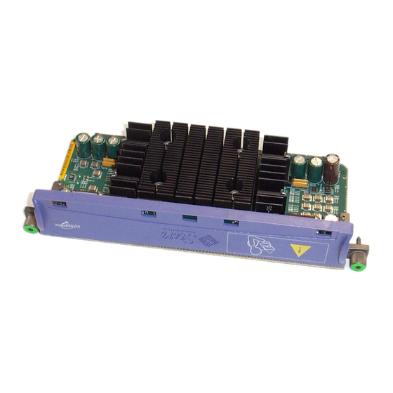
Note – UltraSPARC III Cu CPU modules are marked “USIII Cu” (see FIGURE 1 UltraSPARC III Cu module UltraSPARC III Cu CPU Module FIGURE 1 Sun Blade 1000 and Sun Blade 2000 UltraSPARC III Cu CPU Module Installation Guide... -
Page 12: Sun Blade 1000 And Sun Blade 2000 Ultrasparc Iii Cu Cpu Module Installation Guide
UltraSPARC III Cu CPU Module Installation Guide To install an UltraSPARC III Cu CPU module(s) in a Sun Blade 1000 or Sun Blade 2000 workstation, perform the following installation procedure. Note – To install an UltraSPARC III 600, 750, or 900 MHz non Cu CPU module in a Sun Blade 1000 workstation, see the “Sun Blade 1000 UltraSPARC III Module... - Page 13 From the menu displayed on the system monitor, select “Shutdown”. Sun Blade 1000 and Sun Blade 2000 UltraSPARC III Cu CPU Module Installation Guide...
- Page 14 FIGURE 2 2. Verify the following: a. The backlit Sun logo on the front panel is off. b. The workstation fans are not spinning. Sun Blade 1000 and Sun Blade 2000 UltraSPARC III Cu Module Installation Guide • January 2002...
- Page 15 FIGURE 3 If necessary, use a Phillips screwdriver to remove the screw and lock block. Lock block Screw Phillips screwdriver Removing the Lock Block FIGURE 3 Sun Blade 1000 and Sun Blade 2000 UltraSPARC III Cu CPU Module Installation Guide...
-
Page 16: Removing The Access Panel
2. Tilt the top of the access panel about an inch away from the chassis. 3. Lift the access panel up. 4. Lift the access panel off. Sun Blade 1000 and Sun Blade 2000 UltraSPARC III Cu Module Installation Guide • January 2002... - Page 17 Depression(2) Access panel Removing the Access Panel FIGURE 4 Sun Blade 1000 and Sun Blade 2000 UltraSPARC III Cu CPU Module Installation Guide...
-
Page 18: Attaching The Disposable Antistatic Wrist Strap
Caution – Wear an antistatic wrist strap and use an antistatic mat when handling Sun Blade 1000 and Sun Blade 2000 components. Before servicing or removing workstation components, attach the strap to your wrist and then to a metal area on the chassis. -
Page 19: About Ultrasparc Iii Cpu Modules
Configuration Rules The following configuration rules apply to both UltraSPARC III and UltraSPARC III Cu CPU modules used in the Sun Blade 1000 and Sun Blade 2000 workstations: You can install one or two UltraSPARC III CPU modules into the workstation motherboard. - Page 20 UltraSPARC III Cu CPU module. If the modules are mixed, the workstation will not boot. Note – UltraSPARC III Cu CPU modules are marked “USIII Cu” (see FIGURE 1 Sun Blade 1000 and Sun Blade 2000 UltraSPARC III Cu Module Installation Guide • January 2002...
-
Page 21: Cpu Module Positions In The Workstation
Torque tool B CPU processor slot 0 screw(2) Captive CPU processor slot 1 Location of CPU Processor Slot 0, Captive Screws, and Torque Tools FIGURE 6 Sun Blade 1000 and Sun Blade 2000 UltraSPARC III Cu CPU Module Installation Guide... -
Page 22: Removing A Cpu Module
2. Remove torque tool A or torque tool B from its holder. Note – Sun manufacturing installs torque tool A or torque tool B in Sun Blade 1000 and Sun Blade 2000 workstations. The torque tools are located in different locations... - Page 23 5. To remove an existing CPU module using torque tool A: a. Alternately rotate the left and right captive screws one turn counterclockwise until the screws are free of the threaded inserts (see FIGURE 8 Sun Blade 1000 and Sun Blade 2000 UltraSPARC III Cu CPU Module Installation Guide...
- Page 24 Place the CPU module on an antistatic mat with the heat sink on the top facing up. Proceed to “Installing a New CPU Module” on page 19. Sun Blade 1000 and Sun Blade 2000 UltraSPARC III Cu Module Installation Guide • January 2002...
- Page 25 FIGURE 9 b. Alternately rotate the left and right captive screws one turn counterclockwise until the screws are free of the threaded inserts (see FIGURE 10 Sun Blade 1000 and Sun Blade 2000 UltraSPARC III Cu CPU Module Installation Guide...
- Page 26 Place the CPU module on an antistatic mat with the heat sink on the top facing 7. Proceed to “Installing a New CPU Module” on page 19. Sun Blade 1000 and Sun Blade 2000 UltraSPARC III Cu Module Installation Guide • January 2002...
-
Page 27: Installing A New Cpu Module
Do not remove the plastic cover from the CPU module connectors until you are ready to install the module into the workstation. Do not grip the module by the heat sink. Sun Blade 1000 and Sun Blade 2000 UltraSPARC III Cu CPU Module Installation Guide... - Page 28 FIGURE 11 Plastic top cover CPU module connector(2) Plastic cover Captive screw(2) CPU module Removing the Plastic Cover From the CPU Module Connectors FIGURE 11 Sun Blade 1000 and Sun Blade 2000 UltraSPARC III Cu Module Installation Guide • January 2002...
- Page 29 Once the CPU module is seated, surface contact between the captive screws and the threaded inserts of the shroud typically occurs in less than one turn of both left and right captive screws. Sun Blade 1000 and Sun Blade 2000 UltraSPARC III Cu CPU Module Installation Guide...
- Page 30 5. Use torque tool B to rotate the left captive screw one turn clockwise (see FIGURE 13 Caution – Do not use a torque tool from another Sun product. The Sun Blade 1000 and Sun Blade 2000 torque tools are specifically designed for your workstation.
- Page 31 8. Return torque tool B to its green plastic holder, then return the holder to its storage location in the hard drive bracket. 9. If necessary install the cover for the CPU shroud (see FIGURE 15 Sun Blade 1000 and Sun Blade 2000 UltraSPARC III Cu CPU Module Installation Guide...
- Page 32 Cover for the CPU shroud Installing the Cover for the Shroud FIGURE 15 Sun Blade 1000 and Sun Blade 2000 UltraSPARC III Cu Module Installation Guide • January 2002...
- Page 33 Seating occurs when both captive screws are evenly torqued to 5 inch-lbs. (58 grams- meter). Torque tool A will click when this adjustment specification is achieved. Sun Blade 1000 and Sun Blade 2000 UltraSPARC III Cu CPU Module Installation Guide...
- Page 34 15. Detach the antistatic wrist strap, replace the access panel, plug in the power cord, and power on the workstation. 16. Proceed to “Finishing the Installation” on page 27. Sun Blade 1000 and Sun Blade 2000 UltraSPARC III Cu Module Installation Guide • January 2002...
-
Page 35: Finishing The Installation
CPU module has been correctly installed. If problems are encountered, verify proper POST operation. See Section 3.4 “Maximum and Minimum Levels of POST” in the Sun Blade 1000 and Sun Blade 2000 Service Manual, 816-3217-10. Sun Blade 1000 and Sun Blade 2000 UltraSPARC III Cu CPU Module Installation Guide... -
Page 36: For More Information
For More Information The Sun Blade 1000 and Sun Blade 2000 Service Manual is available from the following sources: The manual is shipped with new workstations in HTML and PDF formats on the Sun Blade 1000 and Sun Blade 2000 Hardware Documentation CD (705-0073-10). The HTML version of the manual on this CD also includes this CPU replacement procedure as an animated ShowMe How™...
Need help?
Do you have a question about the Sun Blade 1000 and is the answer not in the manual?
Questions and answers