Sun Microsystems Sun Fire E25K Installation Manual
High-end and midrange systems cpu/memory board
Hide thumbs
Also See for Sun Fire E25K:
- Service manual (256 pages) ,
- Hardware installation and uninstallation manual (62 pages) ,
- Manual (6 pages)
Table of Contents
Advertisement
Quick Links
™
Sun Fire
High-End and Midrange Systems
CPU/Memory Board Installation Guide
Sun Fire E25K/E20K Systems
Sun Fire 15K/12K Systems
Sun Fire E6900/E4900 Systems
Sun Fire 6800/4810/4800/3800 Systems
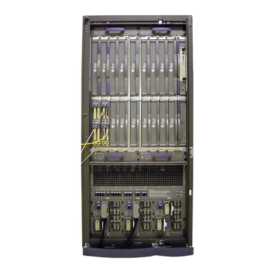
Locations of the CPU/Memory Boards
System
Sun Fire E25K
Sun Fire 15K
Sun Fire E20K
Sun Fire 12K
Sun Fire E6900
Sun Fire 6800
Sun Fire E4900
Sun Fire 4810
Sun Fire 4800
Sun Fire 3800
Number of
CPU/Memory
Board Slots
18
18
9
9
6
6
3
3
3
2
Slot Numbers
SB0-SB17
SB0-SB17
SB0-SB8
SB0-SB8
SB0–SB5
SB0–SB5
SB0, SB2, SB4
SB0, SB2, SB4
SB0, SB2, SB4
SB0, SB2
Location
Front and rear
Front and rear
Front
Front
Front
Front
Rear
Rear
Rear
Front
Advertisement
Table of Contents

Related Manuals for Sun Microsystems Sun Fire E25K


Summary of Contents for Sun Microsystems Sun Fire E25K
- Page 1 ™ Sun Fire High-End and Midrange Systems CPU/Memory Board Installation Guide Sun Fire E25K/E20K Systems Sun Fire 15K/12K Systems Sun Fire E6900/E4900 Systems Sun Fire 6800/4810/4800/3800 Systems Locations of the CPU/Memory Boards Number of CPU/Memory System Board Slots Slot Numbers...
- Page 2 Caution – The CPU/Memory board is heavy and weighs approximately 17-22 pounds (7-9 kilograms). Take care when removing the board from the system. Note – A CPU/Memory board field-replaceable unit (FRU) is for maintenance use only. FRUs must not be used to upgrade CPU performance in systems.
- Page 3 b. Insure the CPU/Memory board alignment tabs are not bent. c. Check the CPU/Memory board springfingers for damage. d. Check the chassis springfingers for damage (SB5 for Sun Fire E6900/6800 and SB4 for Sun Fire E4900/ 4800 systems.) 4. Make sure that the new CPU/Memory board ejector levers are 90 degrees straight out from the board. Ejector levers Installing a CPU/Memory Board The top of the board is identified by a thin rail.
- Page 4 a. Hold the board by the handle vertically with one hand. Place the other hand under the bottom mounting rail. b. Install the board in the chassis by tipping the handle of the board down so that the bottom rail meets the bottom chassis guide rail.
- Page 5 3. Place a grounded ESD mat close to the system. 4. Wear an ESD strap and connect it to the system. Removing a CPU/Memory Board Caution – You must insert a replacement board or filler board into the system within one minute of removing a CPU/Memory board, or overheating will occur.
- Page 6 Copyright 2004 Sun Microsystems, Inc. All rights reserved. Use is subject to license terms. Third-party software, including font technology, is copyrighted and licensed from Sun suppliers. Portions may be derived from Berkeley BSD systems, licensed from U. of CA. Sun, Sun Microsystems, the Sun logo, Sun Fire, and Solaris are trademarks or registered trademarks of Sun Microsystems, Inc.
Need help?
Do you have a question about the Sun Fire E25K and is the answer not in the manual?
Questions and answers