Mitsubishi Electric Q26UD(E)HCPU User Manual
Melsecq series
Hide thumbs
Also See for Q26UD(E)HCPU:
- User manual (622 pages) ,
- User manual (580 pages) ,
- User manual (220 pages)
Table of Contents
Advertisement
Quick Links
QCPU User's Manual
(Hardware Design, Maintenance and Inspection)
-Q00(J)CPU
-Q01CPU
-Q02(H)CPU
-Q06HCPU
-Q12HCPU
-Q25HCPU
-Q02PHCPU
-Q06PHCPU
-Q12PHCPU
-Q25PHCPU
-Q12PRHCPU
-Q25PRHCPU
-Q00U(J)CPU
-Q01UCPU
-Q02UCPU
-Q03UD(E)CPU
-Q03UDVCPU
-Q04UD(E)HCPU
-Q04UDVCPU
-Q06UD(E)HCPU
-Q06UDVCPU
-Q10UD(E)HCPU
-Q13UD(E)HCPU
-Q13UDVCPU
-Q20UD(E)HCPU
-Q26UD(E)HCPU
-Q26UDVCPU
-Q50UDEHCPU
-Q100UDEHCPU
Advertisement
Table of Contents

Related Manuals for Mitsubishi Electric Q26UD(E)HCPU


Summary of Contents for Mitsubishi Electric Q26UD(E)HCPU
- Page 1 QCPU User's Manual (Hardware Design, Maintenance and Inspection) -Q00(J)CPU -Q26UD(E)HCPU -Q01CPU -Q26UDVCPU -Q02(H)CPU -Q50UDEHCPU -Q06HCPU -Q100UDEHCPU -Q12HCPU -Q25HCPU -Q02PHCPU -Q06PHCPU -Q12PHCPU -Q25PHCPU -Q12PRHCPU -Q25PRHCPU -Q00U(J)CPU -Q01UCPU -Q02UCPU -Q03UD(E)CPU -Q03UDVCPU -Q04UD(E)HCPU -Q04UDVCPU -Q06UD(E)HCPU -Q06UDVCPU -Q10UD(E)HCPU -Q13UD(E)HCPU -Q13UDVCPU -Q20UD(E)HCPU...
-
Page 3: Safety Precautions
SAFETY PRECAUTIONS (Read these precautions before using this product.) Before using this product, please read this manual and the relevant manuals carefully and pay full attention to safety to handle the product correctly. In this manual, the safety precautions are classified into two levels: " WARNING"... - Page 4 [Design Precautions] WARNING ● In an output module, when a load current exceeding the rated current or an overcurrent caused by a load short-circuit flows for a long time, it may cause smoke and fire. To prevent this, configure an external safety circuit, such as a fuse.
- Page 5 [Installation Precautions] CAUTION ● Use the programmable controller in an environment that meets the general specifications in this manual. Failure to do so may result in electric shock, fire, malfunction, or damage to or deterioration of the product. ● To mount the module, while pressing the module mounting lever in the lower part of the module, fully insert the module fixing projection(s) into the hole(s) in the base unit and press the module until it snaps into place.
- Page 6 Pulling the connected cable can result in malfunction or damage of the module or the cable. ● Mitsubishi Electric programmable controllers must be installed in control panels. Connect the main power supply to the power supply module in the control panel through a relay terminal block. Wiring and replacement of a power supply module must be performed by maintenance personnel who is familiar with protection against electric shock.
- Page 7 [Startup and Maintenance Precautions] WARNING ● Do not touch any terminal while power is on. Doing so will cause electric shock. ● Correctly connect the battery connector. Do not charge, disassemble, heat, short-circuit, solder, or throw the battery into the fire, or apply liquid or a strong shock to the battery. Doing so will cause the battery to produce heat, explode, ignite, or liquid spill, resulting in injury and fire.
- Page 8 [Disposal Precautions] CAUTION ● When disposing of this product, treat it as industrial waste. When disposing of batteries, separate them from other wastes according to the local regulations. (For details of the Battery Directive in EU countries, refer to Page 678, Appendix 12.) [Transportation Precautions] CAUTION ●...
-
Page 9: Conditions Of Use For The Product
CONDITIONS OF USE FOR THE PRODUCT (1) Mitsubishi programmable controller ("the PRODUCT") shall be used in conditions; i) where any problem, fault or failure occurring in the PRODUCT, if any, shall not lead to any major or serious accident; and ii) where the backup and fail-safe function are systematically or automatically provided outside of the PRODUCT for the case of any problem, fault or failure occurring in the PRODUCT. -
Page 10: Introduction
Q04UD(E)HCPU, Q04UDVCPU, Q06UD(E)HCPU, Q06UDVCPU, Universal model QCPU Q10UD(E)HCPU, Q13UD(E)HCPU, Q13UDVCPU, Q20UD(E)HCPU, Q26UD(E)HCPU, Q26UDVCPU, Q50UDEHCPU, Q100UDEHCPU Precautions when using the Q series CPU module for the first time Memory must be formatted using a programming tool before first use of the CPU module. - Page 11 Memo...
-
Page 12: Table Of Contents
CONTENTS CONTENTS SAFETY PRECAUTIONS ............. 1 CONDITIONS OF USE FOR THE PRODUCT . - Page 13 CHAPTER 6 CPU MODULE Part Names............. . . 119 6.1.1 Basic model QCPU .
- Page 14 9.3.1 Battery installation into the memory card ........241 CHAPTER 10 SD MEMORY CARD 10.1 Part Names.
- Page 15 15.3.5 Socket communication function ..........294 15.3.6 MC protocol function .
- Page 16 Appendix 8.1.5 Power supply part of the power supply module, Q00JCPU, and Q00UJCPU ............662 Appendix 8.1.6 Precautions when using a MELSEC-A series module .
-
Page 17: Manuals
MANUALS To understand the main specifications, functions, and usage of the CPU module, refer to the basic manuals. Read other manuals as well when using a different type of CPU module and its functions. Order each manual as needed, referring to the following lists. The numbers in the "CPU module"... - Page 18 (2) Programming manual CPU module Manual name Description < Manual number (model code) > MELSEC-Q/L Programming Manual (Common Detailed description and usage of instructions Instruction) ● ● ● ● ● used in programs <SH-080809ENG, 13JW10> MELSEC-Q/L/QnA Programming Manual (SFC) System configuration, specifications, functions, programming, and error codes for SFC <SH-080041, 13JF60>...
- Page 19 (4) Intelligent function module manual CPU module Manual name Description < Manual number (model code) > CC-Link IE Controller Network Reference Manual Specifications, procedures and settings before system operation, parameter setting, programming, and troubleshooting of the CC- <SH-080668ENG, 13JV16> Link IE Controller Network module MELSEC-Q CC-Link IE Field Network Master/Local Specifications, procedures and settings before Module User's Manual...
- Page 20 (5) Others CPU module Manual name Description < Manual number (model code) > iQ Sensor Solution Reference Manual Operating methods of iQ Sensor Solution, such <SH-081133ENG, 13JV28> as programming and monitoring CC-Link IE Field Network Basic Reference Manual Specifications, procedures before operation, system configuration, programming, functions, parameter settings, and troubleshooting of CC- <SH-081684ENG, 13JX62>...
-
Page 21: Manual Page Organization
MANUAL PAGE ORGANIZATION In this manual, pages are organized and the symbols are used as shown below. The following page illustration is for explanation purpose only, and is different from the actual pages. "" is used for screen names and items. The chapter of the current page is shown. - Page 22 Menu bar [Online] [Write to PLC...] Select [Online] on the menu bar, and then select [Write to PLC...]. A window selected in the view selection area is displayed. [Parameter] Project window [PLC Parameter] Select [Project] from the view selection area to open the Project window. In the Project window, expand [Parameter] and select [PLC Parameter].
-
Page 23: Terms
Q20UDEHCPU, Q26UDVCPU, Q26UDEHCPU, Q50UDEHCPU, and Q100UDEHCPU Generic term for the Q03UDVCPU, Q04UDVCPU, Q06UDVCPU, Q13UDVCPU, and High-speed Universal model QCPU Q26UDVCPU Generic term for the Mitsubishi Electric motion controllers: Q172CPUN, Q173CPUN, Motion CPU Q172HCPU, Q173HCPU, Q172CPUN-T, Q173CPUN-T, Q172HCPU-T, Q173HCPU-T, Q172DCPU, Q173DCPU, Q172DCPU-S1, Q173DCPU-S1, Q172DSCPU, and Q173DSCPU... - Page 24 Term Description Base unit type Generic term for the main base unit, extension base unit, slim type main base unit, redundant Base unit power main base unit, redundant power extension base unit, redundant type extension base unit base unit, and multiple CPU high speed main base unit ...
- Page 25 Generic term for the QC10TR and QC30TR tracking cables for the Redundant CPU Generic term for the Q6BAT, Q7BAT, and Q8BAT CPU module batteries, Q2MEM-BAT SRAM Battery card battery, and Q3MEM-BAT SRAM card battery Generic term for Mitsubishi Electric Graphic Operation Terminal, GOT-A*** series, GOT-F*** series, GOT1000 series, and GOT2000 series...
-
Page 26: Packing List
PACKING LIST The following items are included in the package of this product. Before use, check that all the items are included. (1) CPU module (a) Q00JCPU or Q00UJCPU Item Quantity Module Battery (Q6BAT) Base unit installation screw (M4 × 14 screw) Safety Guidelines (IB-0800423) (b) Other than Q00JCPU and Q00UJCPU Item... -
Page 27: Discontinued Models
DISCONTINUED MODELS The following models are described in this manual, but have no longer been produced. For the onerous repair term after discontinuation of production, refer to "WARRANTY". Model Production discontinuation Q61P-A1 March 2009 Q61P-A2 March 2009 Q64P February 2010 L1MEM-2GBSD July 2015 L1MEM-4GBSD... -
Page 28: Chapter 1 Overview
Q04UD(E)HCPU, Q04UDVCPU, Q06UD(E)HCPU, Q06UDVCPU, Q10UD(E)HCPU, Q13UD(E)HCPU, Q13UDVCPU, Q20UD(E)HCPU, Q26UD(E)HCPU, Q26UDVCPU, Q50UDEHCPU, Q100UDEHCPU: 4096 points (X/Y0 to FFF) Up to 8192 points (X/Y0 to 1FFF) are supported as the number of I/O device points usable for the remote I/O stations in the MELSECNET/H remote I/O network and CC-Link data link. - Page 29 15K steps Q02UCPU 20K steps Q03UD(E)CPU, Q03UDVCPU 30K steps Q04UD(E)HCPU, Q04UDVCPU 40K steps Q06UD(E)HCPU, Q06UDVCPU 60K steps Universal model QCPU Q10UD(E)HCPU 100K steps Q13UD(E)HCPU, Q13UDVCPU 130K steps Q20UD(E)HCPU 200K steps Q26UD(E)HCPU, Q26UDVCPU 260K steps Q50UDEHCPU 500K steps Q100UDEHCPU 1000K steps...
- Page 30 40ns Q03UD(E)CPU 20ns Q04UD(E)HCPU, Q06UD(E)HCPU, Universal model QCPU Q10UD(E)HCPU, Q13UD(E)HCPU, 9.5ns Q20UD(E)HCPU, Q26UD(E)HCPU, Q50UDEHCPU, Q100UDEHCPU Q03UDVCPU, Q04UDVCPU, Q06UDVCPU, Q13UDVCPU, 1.9ns Q26UDVCPU The MELSEC Q series base unit high-speed system bus has achieved faster access to an intelligent function module and link refresh with a network module.
- Page 31 CHAPTER 1 OVERVIEW (4) Increase in debugging efficiency through high-speed communication with a programming tool High-speed communications at 115.2Kbps maximum are available by using RS-232 which reducing the time required for writing and reading of programs and monitoring. Also, the communication time efficiency of debugging has been increased.
- Page 32 (7) Connection of up to 7 extension base units Up to seven extension base units can be connected to the Q series CPU module. The overall extension cable length is 13.2m, which allows flexible layout of base units. (8) Memory extension By extending the memory capacity of a CPU module, large size files can be managed.
- Page 33 CHAPTER 1 OVERVIEW (9) Automatic write to the standard ROM Note 1.1 Note 1.2 Note 1.1, Note 1.2 Parameters and programs in a memory card or SD memory card can be written to the standard ROM of the CPU module without using a programming tool. If the boot operation is being performed from the standard ROM, parameters and programs in a memory card or SD memory card can be written to the standard ROM by inserting it to the CPU module.
- Page 34 (14)Support of redundant power supply systems The redundant power supply system can be configured using a redundant base unit and redundant power supply modules. The system can continue operation even if one of the power supply modules fails, since the other will supply the power.
-
Page 35: Chapter 2 System Configuration
CHAPTER 2 SYSTEM CONFIGURATION CHAPTER 2 SYSTEM CONFIGURATION This chapter describes system configurations, precautions, and components of the Q Series CPU module. This section describes system configurations for a single CPU system with the Basic model QCPU, High Performance model QCPU, Process CPU, or Universal model QCPU, and a system configuration when using GOT by bus connection. -
Page 36: Overall Configuration
Overall Configuration Extended SRAM cassette Memory card, SD memory card Basic model QCPU High Performance model QCPU Process CPU Universal model QCPU Battery for QCPU (Q6BAT) Q7BAT-SET B main base unit RB redundant power main base unit SB slim type main base unit DB multiple CPU high speed main base unit Battery holder Battery for QCPU (Q7BAT) -
Page 37: Component List
CHAPTER 2 SYSTEM CONFIGURATION Component List (1) Basic model QCPU Item Description Main base unit Q33B, Q35B, Q38B, Q312B Redundant power main base unit Q38RB Applicable main base unit Slim type main base unit Q32SB, Q33SB, Q35SB Multiple CPU high speed main base unit Q35DB, Q38DB, Q312DB Model requiring no power supply module Q52B, Q55B... - Page 38 (2) High Performance model QCPU Item Description Main base unit Q33B, Q35B, Q38B, Q312B Redundant power main base unit Q38RB Applicable main base unit Slim type main base unit Q32SB, Q33SB, Q35SB Multiple CPU high speed main base unit Q35DB, Q38DB, Q312DB Model requiring no power supply module Q52B, Q55B Model requiring a Q series power supply module...
- Page 39 CHAPTER 2 SYSTEM CONFIGURATION (3) Process CPU Item Description Main base unit Q33B, Q35B, Q38B, Q312B Applicable main base unit Redundant power main base unit Q38RB Multiple CPU high speed main base unit Q35DB, Q38DB, Q312DB Model requiring no power supply module Q52B, Q55B Applicable extension base Model requiring a Q-series power supply module...
- Page 40 (4) Universal model QCPU Item Description Main base unit Q33B, Q35B, Q38B, Q312B Applicable main base Redundant power main base unit Q38RB unit slim type main base unit Q32SB, Q33SB, Q35SB Multiple CPU high speed main base unit Q35DB, Q38DB, Q312DB Model requiring no power supply module Q52B, Q55B Model requiring a Q-series power supply module...
-
Page 41: Precautions For System Configuration
CHAPTER 2 SYSTEM CONFIGURATION Precautions for System Configuration This section describes restrictions on the system configuration using the Q series CPU module. (1) Number of mountable modules The number of mountable modules and supported functions are restricted depending on the module type. (a) When the Basic model QCPU is used Maximum number of Product... - Page 42 (b) When the High Performance model QCPU or Process CPU is used Maximum number of modules/units Product Model per system CC-Link IE Controller Network • QJ71GP21-SX Up to 2 modules • QJ71GP21S-SX module • QJ71LP21 • QJ71BR11 Up to 4 modules in •...
- Page 43 CHAPTER 2 SYSTEM CONFIGURATION (c) When the Redundant CPU is used For the modules with restriction on the number of mountable modules, refer to the following. QnPRHCPU User's Manual (Redundant System) (d) When the Universal model QCPU is used Maximum number of Product Model modules/units per system...
- Page 44 One CPU module can control the following number of modules by setting CC-Link network parameters in a programming tool. • Q00UJCPU, Q00UCPU, Q01UCPU: up to 2 modules • Q02UCPU: up to 4 modules • CPU modules other than above: up to 8 modules There is no restriction on the number of modules when the parameters are set with the CC-Link dedicated instructions.
- Page 45 CHAPTER 2 SYSTEM CONFIGURATION (2) Modules with restrictions when used with the Built-in Ethernet port QCPU The following table lists modules with restrictions when used with the Built-in Ethernet port QCPU. Product Model Serial number (first five digits) QJ71LP21-25 QJ71LP21S-25 Some modules have restrictions depending on MELSECNET/H module QJ71LP21G...
- Page 46 (6) Precautions for the number of mountable modules Mount modules so that the total number of I/O points does not exceed the point range of the CPU module. Modules can be mounted in any slot within the available range. Even if the total number of slots of the main base unit and extension base units exceeds the number of available slots (for example, even if six12-slot base units are used), no error occurs as long as modules are mounted within the available range.
- Page 47 CHAPTER 2 SYSTEM CONFIGURATION (7) Precautions when using AnS/A series modules 1) When using the AnS series special function modules shown below, a limitation is placed on an accessible device range. • A1SJ71J92-S3 type JEMANET interface module • A1SD51S type intelligent communication module Device Accessible device range Input (X), Output (Y)
- Page 48 4) System configurations and functions are partially restricted when writing the parameters set under the "High speed interrupt fixed scan interval" setting. For the restrictions, refer to the following. User's manual for the CPU module used (Function Explanation, Program Fundamentals) 5) For the restrictions on mounting an AnS series module on the QA1S6ADP+A1S5oB/A1S6oB, refer to the following.
-
Page 49: Bus Connection Of Got
CHAPTER 2 SYSTEM CONFIGURATION 2.3.1 Bus connection of GOT In the system with the Q series CPU module, the GOT can be bus-connected using the extension cable connector of the main base unit or extension base unit. This section describes the system configuration when a GOT is bus-connected to the CPU module. For details of bus-connection of GOT, refer to the following. - Page 50 (3) Precautions • When a GOT is bus-connected to the CPU module, connect the GOT after the last base unit in the system. Do not position the GOT between base units. • Extension cables for connecting a GOT on the bus must be a maximum of 13.2m in total length. •...
- Page 51 CHAPTER 2 SYSTEM CONFIGURATION (4) Outline of system configuration Main base unit The figure shows the configuration when 16-point modules are loaded to each slot. Q35B (5 slots occupied) ..Slot number ..I/O number Q series CPU module power supply module Extension base unit The figure shows the configuration when 16-point modules are loaded to each slot.
- Page 52 Note 2.1 Maximum number • Q00JCPU and Q00UJCPU: 2 of connectable • Q00CPU, Q01CPU, Q00UCPU, Q01UCPU, or extension base units The final level is for GOT only. Q02UCPU: 4 (for GOT bus • CPU modules other than above: 7 connection) •...
-
Page 53: Peripheral Device Configuration
CHAPTER 2 SYSTEM CONFIGURATION 2.3.2 Peripheral device configuration This section describes peripheral devices that can be used in a system where the Basic model QCPU, High Performance model QCPU, Process CPU, or Universal model QCPU is installed. (1) When the Basic model QCPU is used Basic model QCPU Personal Computer (GX Works2, GX Developer, GX Configurator) * RS-232 cable... - Page 54 For inquiries and orders of a programming unit (EPU01) and connection cable (EPU20R2CBL), please contact your local Mitsubishi Electric Engineering Co., Ltd. sales office. Programming units cannot be used when the "High speed interrupt fixed scan interval" parameter is written to the High...
- Page 55 CHAPTER 2 SYSTEM CONFIGURATION (3) When the Process CPU is used Process CPU Memory card Personal Computer RS-232 cable (GX Works2, GX Developer, GX Configurator, PX Developer) PC card Memory card USB cable adapter (Connector type B) Format ATA cards by a programming tool only. ( Page 240, Section 9.3) For the writing method to a memory card and USB cables, refer to the following.
- Page 56 (4) When the Universal model QCPU is used (a) QnU(D)(H)CPU Universal model QCPU Memory card Personal Computer RS-232 cable (GX Works2, GX Developer, GX Configurator) PC card Memory card USB cable adapter (Connector type B) Format ATA cards by a programming tool only. ( Page 240, Section 9.3) For the writing method to a memory card and USB cables, refer to the following.
- Page 57 CHAPTER 2 SYSTEM CONFIGURATION (b) QnUDVCPU Universal model QCPU Extended SRAM cassette SD memory card Personal Computer (GX Works2) Ethernet cable USB cable (Connector type miniB) For the writing method to an SD memory card, refer to the following. GX Works2 Version 1 Operating Manual (Common) For USB cables, refer to the following.
- Page 58 (c) QnUDE(H)CPU Universal model QCPU Memory card Personal Computer (GX Works2, GX Developer, Ethernet cable GX Configurator) Memory card PC card USB cable adapter (Connector type miniB) Format ATA cards by a programming tool only. ( Page 240, Section 9.3) For the writing method to a memory card and USB cables, refer to the following.
-
Page 59: Chapter 3 Cpu Module Start-Up Procedures
CHAPTER 3 CPU MODULE START-UP PROCEDURES CHAPTER 3 CPU MODULE START-UP PROCEDURES This chapter provide the start-up procedure for the Q Series CPU module on the assumption that programs and parameters have been created separately. For the start-up procedures for a redundant system configured with a Redundant CPU, refer to the following. QnPRHCPU User's Manual (Redundant System) Start Module installation... - Page 60 (From previous page) Memory formatting Operating manual for the • • • Format the memory to be used by the "PC Memory Formatting" of Programming programming tool used tool. Writing the parameters and programs Operating manual for the • • • programming tool used Write the parameters and programs created by the programming tool into the CPU module.
-
Page 61: Chapter 4 Installation And Wiring
CHAPTER 4 INSTALLATION AND WIRING CHAPTER 4 INSTALLATION AND WIRING Installation Environment and Installation Position 4.1.1 Installation environment Install the programmable controller according to the installation environment shown in the general specifications. Page 117, CHAPTER 5) Do not install the programmable controller to the place where: •... -
Page 62: Installation Position
4.1.2 Installation position When installing the programmable controller to a control panel, fully consider its operability, maintainability, and environmental resistance. (1) Installation position To ensure good ventilation and ease module change, provide clearance between the module top/bottom and structures/parts as shown below. (a) In case of main base unit or extension base unit Indicates the control panel top, wiring duct or any part position. - Page 63 CHAPTER 4 INSTALLATION AND WIRING (b) In case of slim type main base unit Indicates the control panel top, wiring duct or any part position. 30mm or Programmable *5, *6 *1, *5 more controller Control Door panel 20mm or 30mm or more *4, *5 more...
- Page 64 (3) Installation surface Install the base unit on a flat surface. If the surface where the base unit is installed is not even, this may strain the printed circuit boards and cause malfunctions. (4) Installation in an area where other devices are installed Do not install a base unit in proximity to vibration sources such as large magnetic contractors and no-fuse circuit breakers.
-
Page 65: Mounting A Module
CHAPTER 4 INSTALLATION AND WIRING Mounting a Module 4.2.1 Mounting precautions This section describes precautions for handling CPU modules, I/O modules, intelligent function modules, power supply modules, and base units. • Do not drop or apply strong shock to the module case, memory card, SD memory card, extended SRAM cassette, terminal block connector, and pin connector. -
Page 66: Base Unit Installation
4.2.2 Base unit installation (1) Installing a base unit on a control panel Install a main base unit, Q00JCPU, and Q00UJCPU (by screwing) in the following procedure. Fit the two base unit top installation screws into the enclosure. Panel Place the right-hand side notch of the base unit onto the right-hand side screw. Panel Place the left-hand side pear-shaped hole onto the left-hand side screw. - Page 67 CHAPTER 4 INSTALLATION AND WIRING (2) Mounting a base unit on a DIN rail Note the following when mounting a DIN rail. Mounting a DIN rail needs special adaptors (optional), which are user-prepared. (a) Applicable adaptor types For Q38B, Q312B, Q68B, Q612B, Q38RB, Q68RB, Q65WRB, Q38DB, Q312DB Q6DIN1 For Q35B, Q35DB, Q65B, Q00JCPU, Q00UJCPU...
- Page 68 (d) Distance between DIN rail mounting screws When using DIN rail, DIN rail mounting screws must be inserted in 200mm distances or less in order to ensure that the rail has sufficient strength. DIN rail mounting screw DIN rail (obtained by user) 35mm P=200mm or less When installing the DIN rail in a frequent vibration and/or shock prone environment, insert the mounting screws...
- Page 69 CHAPTER 4 INSTALLATION AND WIRING • For Q00JCPU, Q00UJCPU, Q33B, Q35B, Q35DB, Q65B, Q52B, Q55B, Q63B, Q32SB, Q33SB or Q35SB type Screw the DIN rail in two places using the mounting screws and square washers included with the adaptors in 'Position A' (bottom of base unit). B *3 A *2 B *3...
- Page 70 (e) Stopper mounting When using the DIN rail in the environment with frequent vibration, use stoppers included with the DIN rail mounting adaptor shown in (a). An example of the use of the DIN rail stopper is described in the following procedure. Fix the module according to the manual of the DIN rail stopper used.
- Page 71 CHAPTER 4 INSTALLATION AND WIRING In addition, when three or more modules with 130mm or more in depth (such as Q66DA-G etc.) are mounted, or when the base unit is used in the environment with extremely frequent vibration, use the Q6DIN1A Q-type base DIN rail mounting adaptor (vibration-proofing bracket kit) where the large mounting bracket is included.
- Page 72 (f) Dimensions when DIN rail is attached (Side view). Control board side DIN rail depth (D) TH35-7.5Fe, TH35-7.5Al:7.5 Base unit Power supply module TH35-15Fe:15 DIN rail adaptor DIN rail: TH35-7.5Fe, TH35-7.5Al, TH35-15Fe Example) Q64PN Power supply module = 115 Unit: mm...
-
Page 73: Installation And Removal Of Module
CHAPTER 4 INSTALLATION AND WIRING 4.2.3 Installation and removal of module This section explains how to install and remove a power supply, CPU, I/O, intelligent function or another module to and from the base unit. (1) Installation and removal of the module on/from Q3B, Q3SB, Q3RB, Q3DB, Q5B, Q6B, Q6RB and Q6WRB ... - Page 74 ● When mounting the module, always insert the module fixing projection into the module fixing hole of the base unit. At that time, securely insert the module fixing projection so that it does not come off from the module fixing hole. Failure to do so may damage the module connector and module.
- Page 75 CHAPTER 4 INSTALLATION AND WIRING (b) Removal of module from Q3 B, Q3 SB, Q3 RB, Q3 DB, Q5 B, Q6 B, Q6 and Q6 Support the module with both hands and securely press the module fixing hook(*1) with your finger.
- Page 76 (2) Installation and removal of the module on/from QA1S5B and QA1S6B (a) Installation of module on QA1S5B and QA1S6B Base unit Insert the module fixing Module projections into the module fixing hole in the base unit. Module connector Using the module fixing hole as Module fixing a support, install the module hole...
- Page 77 CHAPTER 4 INSTALLATION AND WIRING (b) Removal of module from QA1S5B and QA1S6B Remove the module mounting screw, and Base unit using the bottom of the module as a support, pull the top of the module toward you. Module connector Module Lift the module upwards Module fixing hole...
- Page 78 (3) Installation and removal of on/from QA6B (a) Installation of module on QA6B Module fixing hole (A) Base unit Hook Module Module connector Insert the two module fixing projections into the module fixing hole (B) in the base unit. Mount the module into the base unit by pushing it in the direction of the arrow.
- Page 79 CHAPTER 4 INSTALLATION AND WIRING (b) Removal from QA6B Hold the module with both hands and Base unit press the hook on the top of module. Module fixing hole (A) Pull the module straight toward you supporting it at its bottom while Module Hook pressing the hook.
-
Page 80: Connecting An Extension Base Unit
Connecting an Extension Base Unit When using two or more extension base units, the base number must be set with their base number setting connectors. (The number of extension bases is set to 1 by factory default.) Since the Q6WRB is fixed to the extension 1, extension base No. setting is not required. 4.3.1 Setting the extension base number Set the extension base number in the following procedure. - Page 81 CHAPTER 4 INSTALLATION AND WIRING Insert the connector pin in the required base number location of the connector (PIN1) existing between the IN and OUT sides of the extension cable connector. Connector pin Number setting for extension bases Extension Extension Extension Extension Extension...
- Page 82 Install the base cover to the extension base unit and tighten the base cover screw. (Tightening torque: 0.36 to 0.48N•m) Fixing screw Base cover Extension base unit Flat blade screwdriver Base cover ● Set extension base numbers in the order of connection, starting from the extension base unit connected to the main base unit.
- Page 83 CHAPTER 4 INSTALLATION AND WIRING (1) Precautions for setting the extension base numbers (a) Setting order Set the extension base number consecutively. In Auto mode, when any extension base number is skipped, no slots will be allocated to an empty extension base so that the slots cannot be reserved.
- Page 84 (b) When the same number is set The same extension number cannot be set for multiple extension base unit. Main base unit Q312B Slot number Power supply CPU module module Extension base unit Q68B Extension 1 The same extension stage number cannot be set! Q68B Extension 1...
- Page 85 CHAPTER 4 INSTALLATION AND WIRING (c) When connector pins are connected in more than 2 positions, or no pin is used The extension base unit cannot be used when connector pins for base number setting are inserted in more than two positions and when not using any connector pin. Main base unit Q312B Slot number...
- Page 86 (e) Extension base positioning for AnS/A series-compatible extension base units (QA1S5B, QA1S6B, QA6B, and QA6ADP+A5B/A6B) When using AnS/A series-compatible extension base units in combination, follow the instructions described below. • Connect the units in order of Q5B/Q6B, QA1S5B/QA1S6B, QA6B, and QA6ADP+A5B/A6B from the nearest position of the main base unit.
-
Page 87: Connection And Disconnection Of Extension Cable
CHAPTER 4 INSTALLATION AND WIRING 4.3.2 Connection and disconnection of extension cable (1) Instructions for handling an extension cable • Do not step on an extension cable. • Connect the extension cable to the base unit with the base cover installed to the base unit. (After you have set the extension number to the extension base unit, reinstall and screw the base cover.) •... - Page 88 (2) Connection of extension cable When connecting an extension base unit to the main base unit with an extension cable, plug the OUT side connector of the main base unit and the IN side connector of the extension base unit with an extension cable. The system will not operate properly if the extension cable is connected in the form of IN to IN, OUT to OUT or IN to OUT.
-
Page 89: Extension Cable Specifications
CHAPTER 4 INSTALLATION AND WIRING When plugging the extension cable to any base unit, hold the connector part of the extension cable. Main base unit Connector Extension cable After fitting the extension cable, always tighten the extension cable connector fixing screws. (Tightening torque: 0.20N•m) Main base unit Fixing screw... -
Page 90: Voltage Drop When An Extension Base Unit Is Used
4.3.4 Voltage drop when an extension base unit is used Since the extension base unit (Q5B or QA1S5B) is supplied with 5VDC from the power supply module on the main base unit, a voltage drop occurs at extension cables. Improper I/O may occur if the specified voltage (4.75VDC or higher) is not supplied to the "IN"... - Page 91 CHAPTER 4 INSTALLATION AND WIRING (b) How to calculate voltage to "IN" connector The 5VDC output voltage of the power supply module on the main base unit is set to at least 4.90VDC. Therefore, the Q5B or QA1S5B can be used if the voltage drop at the extension cable is 0.15VDC or lower (4.9VDC - 4.75VDC = 0.15VDC).
- Page 92 Voltage drop at extension cable on corresponding extension unit Sum total of Q5B, voltage drops to QA1S5B "IN" connector Installation of Q5B or position QA1S5B (V) Extension 1 R1•I1 ---- ---- ---- ---- ---- ---- V=V1 Extension 2 R1 (I1+I2) R2•I2 ---- ----...
- Page 93 CHAPTER 4 INSTALLATION AND WIRING (2) When the Q6B or QA1S6B is connected between the main base unit and the Q5B or QA1S5B (a) Selection condition 4.75VDC or higher must be supplied to the "IN" connector of the Q5B or QA1S5B in the final extension base.
- Page 94 (3) When the GOT is bus-connected (a) Selection condition 4.75VDC or higher should be supplied to the "IN" connector of the Q5B in the final extension. (b) How to calculate voltage to "IN" connector The 5VDC output voltage of the power supply module on the main base unit is set to at least 4.90VDC. Therefore, the Q5B can be used if the voltage drop is 0.15VDC or lower (4.9VDC -4.75VDC = 0.15VDC).
- Page 95 CHAPTER 4 INSTALLATION AND WIRING Position of extension base unit Number of bases Voltage drop caused by extension cable from the for GOT bus main base unit to the Q5B IN connector (V) Q6B Q5B connection Extension 1 Extension 2 Extension 3 V=(R1+R2)(I1+Im) Extension 1, Extension 2...
-
Page 96: Mounting And Removing A Terminal Block
Mounting and Removing a Terminal Block This section describes a procedure for mounting and removing an 18-point terminal block. (1) Removal procedure Open the terminal cover and loosen the terminal block mounting screw. Terminal block mounting screw Remove the terminal block. (2) Mounting procedure Place the terminal block in position, and then tighten the two terminal block mounting screws (upper and lower). -
Page 97: Installing And Removing A Memory Card
CHAPTER 4 INSTALLATION AND WIRING Installing and Removing a Memory Card Note 4.1 This section describes a procedure for installing and removing a memory card. Note 4.1 (1) For Q2MEM type memory cards (a) Installing a memory card Pay attention to the direction of a memory card. Insert the card securely into the connector of a CPU module until the height of the card reaches that of the memory card EJECT button. - Page 98 (2) For Q3MEM type memory cards (a) Installing a memory card Pay attention to the direction of a memory card and install the card according to the following procedure. Remove the cover, slightly bending Install the memory card CPU module the center of the cover to make space between the projection and the mounting hole.
- Page 99 CHAPTER 4 INSTALLATION AND WIRING (b) Removing a memory card When removing a memory card from the CPU module, remove a memory card protective cover and press the EJECT button to pull out the memory card. Remove a memory card protective cover, press the memory card EJECT button, and pull out the memory card. Remove the protective cover, pressing the fixing claws located on...
- Page 100 Observe the following precautions when installing or removing a memory card while power is on. ● Note that the data in a memory card may be damaged if the above procedure is not followed. If the operating status of the CPU module at the time of an error is set to "Stop"...
-
Page 101: Installing And Removing An Sd Memory Card
CHAPTER 4 INSTALLATION AND WIRING Installing and Removing an SD Memory Card Note 4.2 This section describes a procedure for installing and removing an SD memory card. Note 4.2 (1) Installing an SD memory card Pay attention to the direction of an SD memory card and install the card according to the following procedure. Insert an SD memory card straight into the SD memory card slot. - Page 102 (2) Removing an SD memory card Pull out the SD memory card according to the following procedure. Disable the access to the SD memory card in either of the following. The SD CARD LED flashes during the access-disabling processing, and turns off when the processing is completed. •...
-
Page 103: Installing And Removing An Extended Sram Cassette
CHAPTER 4 INSTALLATION AND WIRING Installing and Removing an Extended SRAM Cassette Note 4.3 This section describes a procedure for installing and removing an extended SRAM cassette. Note 4.3 (1) Installing an extended SRAM cassette Insert an extended SRAM cassette while the power is off. Open the cassette cover on the side of the CPU module. - Page 104 ● The data stored in the standard RAM before an extended SRAM cassette is installed are retained even after the cassette is installed. ● The capacity of the standard RAM after installation can be checked on the "Online Data Operation" window. [Online] [Read from PLC] (2) Removing an extended SRAM cassette...
-
Page 105: Wiring
CHAPTER 4 INSTALLATION AND WIRING Wiring 4.8.1 Wiring power supplies (1) Precautions for wiring power supplies • Wire cables of the programmable controller power supply, I/O power supply, and motor power supply separately as shown below. Programmable Isolation Main transformer controller power power supply supply... - Page 106 • Momentary power failure may be detected or the CPU module may be reset due to serge caused by lightning. As measures against a noise caused by surge, connect a surge absorber for lightning as shown in the following figure. Using the surge absorber for lightning can reduce the influence of lightning.
- Page 107 CHAPTER 4 INSTALLATION AND WIRING (2) Wiring examples The following figures show wiring examples of cables such as power cables and ground wires to the main base unit and extension base units. (a) Single power supply system Main base unit 100/110VAC (Q38B) CPU module...
- Page 108 (b) Redundant power supply system • Q64RPN System A System B 100V/200VAC Redundant power main base unit (Q38RB) Q64RPN Q64RPN CPU module *1, *2 *1, *2 100V/200VAC INPUT INPUT 100-240VAC 100-240VAC Redundant power extension base unit (Q68RB) Extension cable Q64RPN Q64RPN I/O module *1, *2...
- Page 109 CHAPTER 4 INSTALLATION AND WIRING • Q64RP System A System B 100V/200VAC Redundant power main base unit (Q38RB) Q64RP Q64RP CPU module *1, *2 *1, *2 100V/200VAC INPUT INPUT 100-120/ 100-120/ 200-240VAC 200-240VAC Redundant power extension base unit (Q68RB) Extension cable Q64RP Q64RP I/O module...
- Page 110 ● Use the thickest possible (max. 2mm ) wires for the 100/200VAC and 24VDC power cables. Twist these wires starting at the connection terminals. Use a solderless terminal for wiring a terminal block. To prevent short-circuit due to loosening screws, use the solderless terminals with insulation sleeves of 0.8mm or less. Note that up to two solderless terminals can be connected per terminal block.
-
Page 111: Wiring Of 18-Point Screw Terminal Block
CHAPTER 4 INSTALLATION AND WIRING 4.8.2 Wiring of 18-point screw terminal block (1) Precautions • Insulation-sleeved crimping terminals cannot be used with the terminal block. It is recommended to cover the wire connections of the crimping terminals with mark or insulation tubes. •... - Page 112 (2) Wiring method (a) Wiring to an 18-point screw terminal block Strip the insulating coating from the cable. Connect a solderless terminal to the stripped part of the cable. For applicable solderless terminals, refer to the specifications of each module. Wire the solderless terminals to the 18-point screw terminal block.
-
Page 113: Wiring To Connectors
CHAPTER 4 INSTALLATION AND WIRING 4.8.3 Wiring to connectors (1) Precautions • Connectors for external devices (A6CON) must be crimped, pressed, or correctly soldered. • Plug connectors for external devices (A6CON) securely to the module and tighten the two screws. •... - Page 114 (3) Wiring method (a) A6CON1, A6CON4 Loosen the four fixing screws on the connector and remove the screws. Open the connector cover from the connector side. Solder the wires and coat them with heat shrinkable tubes. Heat shrinkable tube Check the terminal layout and install the wires to the connector.
- Page 115 CHAPTER 4 INSTALLATION AND WIRING Place the connector on one side of the connector cover and put the fixing screws through the screw holes. Cover the other connector cover onto the connector. Tighten the four screws.
- Page 116 (b) A6CON2 The following table lists the specifications of the FCN-363T-T005/H used for the A6CON2. Outside Applicable wire Cross-section area of Length of stripped Crimp height diameter of size wire wire part coated wire 1.2 or less 24 AWG 1.25 to 1.30 3.0 to 4.0 0.20 to 0.24mm 1.2 or less...
- Page 117 CHAPTER 4 INSTALLATION AND WIRING (4) Plugging a connector (a) Installation procedure Plug the connector into the slot on the module. Connector screw Tighten the two connector screws (M2.6). (b) Removal procedure Loosen the two connector screws, and then pull out the connector horizontally to the module.
-
Page 118: Grounding
4.8.4 Grounding For grounding, perform the following: • Use a dedicated grounding wire as far as possible. (Grounding resistance of 100 or less.) • When a dedicated grounding cannot be provided, use (2) Shared grounding shown below. Programmable Programmable Programmable Equipment Equipment Equipment... -
Page 119: Chapter 5 General Specifications
The operating ambient humidity and storage ambient humidity are 10 to 90%RH if the system includes the AnS/A series modules. Do not use or store the programmable controller under pressure higher than the atmospheric pressure of altitude 0m. Doing so may cause malfunction. When using the programmable controller under pressure, please consult your local Mitsubishi Electric representative. - Page 120 Memo...
-
Page 121: Chapter 6 Cpu Module
CHAPTER 6 CPU MODULE CHAPTER 6 CPU MODULE Part Names 6.1.1 Basic model QCPU (1) Q00JCPU When opening the cover, When opening the cover, put your finger here. put your finger here. 12) 13) INPUT 10) 9) 100-240VAC 50/60Hz 105VA OUTPUT 5VDC3A INPUT... - Page 122 Name Application Base unit installation hole Pear-shaped hole for installing the unit on a panel such as a control panel. (For M4 screw) Protective cover for extension cable connector. Remove this cover when connecting an Cover extension base unit. Connector for transferring signals to or from the extension base unit. Connect an extension Extension cable connector cable.
- Page 123 CHAPTER 6 CPU MODULE Name Application Connector for connecting a peripheral device by RS-232. RS-232 connector Can be connected by the RS-232 connection cable (QC30R2). RUN: Executes sequence program operation. STOP: Stops sequence program operation. RESET: RUN/STOP/RESET switch Performs hardware reset, operation error reset, operation initialization or like. Page 182, Section 6.4.1) When a cable is connected to the RS-232 connector at all times, clamp the cable to prevent a poor connection, moving, and disconnection by unintentional pulling.
- Page 124 (2) Q00CPU, Q01CPU When opening the cover, put your finger here.
- Page 125 CHAPTER 6 CPU MODULE Name Application Module fixing hook Hook used to fix the module to the base unit. (Single-motion installation) Indicates the operating status of the CPU module. On: During operation with the RUN/STOP/RESET switch set to "RUN". Off: During stop with the RUN/STOP/RESET switch set to "STOP". When the error that stops operation is detected Flash: When parameters/program is written during STOP and the RUN/STOP/RESET switch is...
- Page 126 When a cable is connected to the RS-232 connector at all times, clamp the cable to prevent a poor connection, moving, and disconnection by unintentional pulling. The Q6HLD-R2 type RS-232 connection disconnection prevention holder is available as a clamp for RS-232 connector. CPU module RS-232 cable Q6HLD-R2...
-
Page 127: High Performance Model Qcpu, Process Cpu And Redundant Cpu
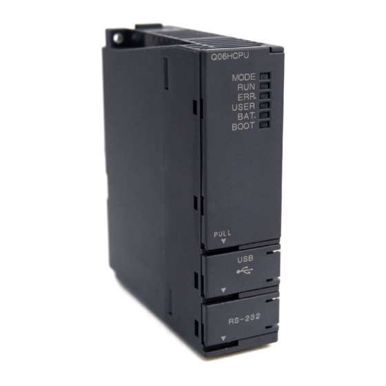
CHAPTER 6 CPU MODULE 6.1.2 High Performance model QCPU, Process CPU and Redundant (1) Q02CPU, Q02HCPU, Q06HCPU, Q12HCPU, Q25HCPU, Q02PHCPU, Q06PHCPU, Q12PHCPU, Q25PHCPU Q02HCPU Q02HCPU MODE MODE ERR. ERR. USER USER BAT. BAT. BOOT BOOT STOP RESET L.CLR PULL RS-232 When opening the cover, put your finger here. - Page 128 (2) Q12PRHCPU, Q25PRHCPU Q12PRHCPU Q12PRHCPU MODE BACKUP MODE BACKUP CONTROL CONTROL ERR. SYSTEM A ERR. SYSTEM A USER USER SYSTEM B SYSTEM B BAT. BAT. BOOT BOOT TRACKING TRACKING STOP RESET L.CLR PULL When opening the cover, put your finger here.
- Page 129 CHAPTER 6 CPU MODULE Name Application Module fixing hook Hook used to secure the module to the base unit. (Single-motion installation) Indicates the mode of the CPU module. MODE LED On (green): Q mode Flash (green): Forced on and off for external I/O registered Indicates the operating status of the CPU module.
- Page 130 Name Application Used to set the items for operation of the CPU module. For the system protection and the valid parameter drives of the DIP switches, refer to the following. Qn(H)/QnPH/QnPRHCPU User's Manual (Function Explanation, Program Fundamentals) DIP switches SW1 : Used to set system protection. Inhibits all the writing and control instructions to the CPU module.
- Page 131 CHAPTER 6 CPU MODULE Name Application Indicates the CPU module operates as control system or standby system. On: Control system (The standby system is normal and system switching is available.) CONTROL LED Off: Standby system Note that this LED turns on in the debug mode. The LED of the CPU module on the system A side turns on.
-
Page 132: Universal Model Qcpu
6.1.3 Universal model QCPU (1) Q00UJCPU When opening the cover, put your finger here. 12) 13) INPUT 10) 9) 100-240VAC 50/60Hz 105VA OUTPUT 5VDC3A INPUT INPUT 100-240VAC... - Page 133 CHAPTER 6 CPU MODULE Name Application Base unit installation hole Pear-shaped hole for installing the unit on a panel such as a control panel. (For M4 screw) Protective cover for extension cable connector. Remove this cover when connecting an Cover extension base unit.
- Page 134 Name Application For connection of the battery lead wires. Battery connector pin (Lead wires are disconnected from the connector when shipping to prevent the battery from consuming.) Connector for connection with USB-compatible peripheral devices. (Connector type miniB) USB connector Can be connected by USB-dedicated cable. Connector for connecting a peripheral device by RS-232.
- Page 135 CHAPTER 6 CPU MODULE (2) Q00UCPU, Q01UCPU Q00UCPU When opening the cover, put your finger here.
- Page 136 Name Application Module fixing hook Hook used to fix the module to the base unit. (Single-motion installation) Indicates the mode of the CPU module. On: Q mode MODE LED Flash: Executional conditioned device test is being executed. External input/output forced on/off function is being executed. Indicates the operating status of the CPU module.
- Page 137 CHAPTER 6 CPU MODULE Name Application Module fixing projection Projection used to secure the module to the base unit. Lever used to mount the module to the base unit. Module mounting lever When leaving a cable connected to a USB connector or RS-232 connector, clamp the cable to prevent a poor connection, moving, and disconnection by unintentional pulling.
- Page 138 (3) Q02UCPU, Q03UDCPU, Q04UDHCPU, Q06UDHCPU, Q10UDHCPU, Q13UDHCPU, Q20UDHCPU, Q26UDHCPU When opening the cover, put your finger here.
- Page 139 CHAPTER 6 CPU MODULE Name Application Module fixing hook Hook used to fix the module to the base unit. (Single-motion installation) Indicates the mode of the CPU module. On: Q mode Flash: MODE LED Executional conditioned device test is being executed. External input/output forced on/off function is being executed.
- Page 140 Name Application For connection of battery lead wires. Battery connector pin (Lead wires are disconnected from the connector when shipping to prevent the battery from consuming.) Battery Backup battery for use of standard RAM and backup power time function. Module mounting lever Lever used to mount the module to the base unit.
- Page 141 CHAPTER 6 CPU MODULE (4) Q03UDVCPU, Q04UDVCPU, Q06UDVCPU, Q13UDVCPU, Q26UDVCPU Do not remove this sticker since it is for Mitsubishi maintenance.
- Page 142 Name Application Module fixing hook Hook used to fix the module to the base unit. (Single-motion installation) Indicates the mode of the CPU module. On: Q mode Flash: Executional conditioned device test is being executed. MODE LED External input/output forced on/off function is being executed. CPU module change function with memory card is being executed.
- Page 143 CHAPTER 6 CPU MODULE Name Application • RUN: Executes sequence program operation. • STOP: Stops sequence program operation. RUN/STOP/RESET switch • RESET: Performs hardware reset, operation error reset, operation initialization or like. Page 182, Section 6.4.1) Connector for connection with USB-compatible peripheral device. (Connector type miniB) USB connector Can be connected by USB-dedicated cable.
- Page 144 (5) Q03UDECPU, Q04UDEHCPU, Q06UDEHCPU, Q10UDEHCPU, Q13UDEHCPU, Q20UDEHCPU, Q26UDEHCPU, Q50UDEHCPU, Q100UDEHCPU When opening the cover, put your finger here.
- Page 145 CHAPTER 6 CPU MODULE Name Application Module fixing hook Hook used to fix the module to the base unit. (Single-motion installation) Indicates the mode of the CPU module. On: Q mode Flash: MODE LED Executional conditioned device test is being executed. External input/output forced on/off function is being executed.
- Page 146 Name Application RUN: Executes sequence program operation. STOP: Stops sequence program operation. RESET: RUN/STOP/RESET switch Performs hardware reset, operation error reset, operation initialization or like. Page 182, Section 6.4.1) Module fixing screw hole Hole for the screw used to secure to the base unit. (M3 × 12 screw) Module fixing projection Projection used to secure the module to the base unit.
-
Page 147: Specifications
CHAPTER 6 CPU MODULE Specifications The following table lists performance specifications of CPU modules. 6.2.1 Basic model QCPU Basic model QCPU Item Q00JCPU Q00CPU Q01CPU Control method Stored program cyclic operation I/O control mode Refresh mode (Direct access I/O is available by specifying direct access I/O (DX, DY).) Sequence control Relay symbol language, logic symbolic language, MELSAP3 (SFC), MELSAP-L, function block, language... - Page 148 Basic model QCPU Item Q00JCPU Q00CPU Q01CPU Program memory Memory card (RAM) ---- Flash Memory Max. number ---- card card of files stored (ROM) ATA card ---- Standard RAM ---- Standard ROM Initial Maximum number of setting intelligent function module parameters Refresh No.
- Page 149 CHAPTER 6 CPU MODULE Basic model QCPU Item Q00JCPU Q00CPU Q01CPU 2048 points (S0 to 127/block) (The number of device points is fixed.) Step relay [S] Index register [Z] 10 points (Z0 to 9) (The number of device points is fixed.) Pointer [P] 300 points (P0 to 299) (The number of device points is fixed.) 128 points (I0 to 127) (The number of device points is fixed.)
-
Page 150: High Performance Model Qcpu
6.2.2 High Performance model QCPU High Performance model QCPU Item Q02CPU Q02HCPU Q06HCPU Q12HCPU Q25HCPU Control method Stored program cyclic operation Refresh mode I/O control mode (Direct access I/O is available by specifying direct access I/O (DX, DY).) Sequence control Relay symbol language, logic symbolic language, MELSAP3 (SFC), MELSAP-L, function block, language and structured text (ST) - Page 151 CHAPTER 6 CPU MODULE High Performance model QCPU Item Q02CPU Q02HCPU Q06HCPU Q12HCPU Q25HCPU Program memory Memory card (RAM) 319 (When the Q3MEM-4MBS is used) Flash Memory Max. number card card of files stored (ROM) ATA card Standard RAM Standard ROM Initial Max.
- Page 152 High Performance model QCPU Item Q02CPU Q02HCPU Q06HCPU Q12HCPU Q25HCPU The following number of device points can be used by switching blocks (in increments of 32768 points (R0 to 32767)). ZR: The following number of device points can be used without switching blocks. Standard 32768 points 65536 points...
- Page 153 CHAPTER 6 CPU MODULE High Performance model QCPU Item Q02CPU Q02HCPU Q06HCPU Q12HCPU Q25HCPU L0 to 8191 (default) Latch range (Latch range can be set up for B, F, V, T, ST, C, D, and W.) (Setting by parameters.) RUN/PAUSE contact One contact can be set up in X0 to 1FFF for each of RUN and PAUSE.
-
Page 154: Process Cpu
6.2.3 Process CPU Process CPU Item Q02PHCPU Q06PHCPU Q12PHCPU Q25PHCPU Control method Stored program cyclic operation Refresh mode I/O control mode (Direct access I/O is available by specifying direct access I/O (DX, DY).) Sequence control Relay symbol language, logic symbolic language, MELSAP3 (SFC), language MELSAP-L, function block and structured text (ST) Program... - Page 155 CHAPTER 6 CPU MODULE Process CPU Item Q02PHCPU Q06PHCPU Q12PHCPU Q25PHCPU Program memory Memory card (RAM) 319 (When the Q3MEM-4MBS is used) Flash Memory Max. number card card of files stored (ROM) ATA card Standard RAM Standard ROM Initial Max. number of intelligent setting function module parameters...
- Page 156 Process CPU Item Q02PHCPU Q06PHCPU Q12PHCPU Q25PHCPU The following number of device points can be used by switching blocks (in increments of 32768 points (R0 to 32767)). ZR: The following number of device points can be used without switching blocks. Standard 65536 points 131072 points...
- Page 157 CHAPTER 6 CPU MODULE Process CPU Item Q02PHCPU Q06PHCPU Q12PHCPU Q25PHCPU L0 to 8191 (default) Latch range (Latch range can be set up for B, F, V, T, ST, C, D, and W.) (Setting by parameters) RUN/PAUSE contact One contact can be set up in X0 to 1FFF for each of RUN and PAUSE. (Setting by parameters) Year, month, date, hour, minute, second, and day of the week (Automatic leap year detection) Clock function...
-
Page 158: Redundant Cpu
6.2.4 Redundant CPU Redundant CPU Item Q12PRHCPU Q25PRHCPU Control method Stored program cyclic operation Refresh mode I/O control mode (Direct access I/O is available by specifying direct access I/O (DX, DY).) Sequence control Relay symbol language, logic symbolic language, MELSAP3 (SFC), language MELSAP-L, function block and structured text (ST) Program... - Page 159 CHAPTER 6 CPU MODULE Redundant CPU Item Q12PRHCPU Q25PRHCPU Program memory Memory card (RAM) 319 (When the Q3MEM-4MBS is used) Flash Memory Max. number card card of files stored (ROM) ATA card Standard RAM Standard ROM Initial Max. number of intelligent setting function module parameters...
- Page 160 Redundant CPU Item Q12PRHCPU Q25PRHCPU The following number of device points can be used by switching blocks (in increments of 32768 points (R0 to 32767)). ZR: The following number of device points can be used without switching blocks. Standard 131072 points SRAM card 517120 points (1M byte)
- Page 161 CHAPTER 6 CPU MODULE Redundant CPU Item Q12PRHCPU Q25PRHCPU L0 to 8191 (default) (Setting by parameters) Latch range (Latch range can be set up for B, F, V, T, ST, C, D, and W.) RUN/PAUSE contact One contact can be set up in X0 to 1FFF for each of RUN and PAUSE. (Setting by parameters) Year, month, date, hour, minute, second, and day of the week (Automatic leap year detection) Clock function...
-
Page 162: Universal Model Qcpu
6.2.5 Universal model QCPU (1) Q00UJCPU, Q00UCPU, Q01UCPU, Q02UCPU Universal model QCPU Item Q00UJCPU Q00UCPU Q01UCPU Q02UCPU Control method Stored program cyclic operation Refresh mode I/O control mode (Direct access I/O is available by specifying direct access I/O (DX, DY).) Relay symbol language, logic symbolic language, MELSAP3 (SFC), Sequence control language Program... - Page 163 CHAPTER 6 CPU MODULE Universal model QCPU Item Q00UJCPU Q00UCPU Q01UCPU Q02UCPU Program memory 319 (When the Memory card (RAM) ---- Q3MEM-8MBS is used) Max. number Flash card ---- Memory card of files stored (ROM) ATA card ---- 4 files (each one of the following files: file register file, local device Standard RAM ---- file, sampling trace file, and module error collection file)
- Page 164 A single write operation may not be counted as one. The count of writing into the program memory can be checked with the special register (SD682 and SD683). A single write operation may not be counted as one. The count of writing into the standard ROM can be checked with the special register (SD687 and SD688). The number of points can be changed within the setting range.
- Page 165 CHAPTER 6 CPU MODULE Universal model QCPU Item Q00UJCPU Q00UCPU Q01UCPU Q02UCPU The following number of device points can be used by switching blocks (in increments of 32768 points (R0 to 32767)). ---- ZR: The following number of device points can be used without switching blocks.
- Page 166 Universal model QCPU Item Q00UJCPU Q00UCPU Q01UCPU Q02UCPU Data transmission speed ---- Communication mode ---- Transmission method ---- Specifi- Max. distance between cations of ---- hub and node built-in Max. Ethernet 10BASE-T ---- number of port CPU connectable 100BASE- module ---- nodes Number of...
- Page 167 CHAPTER 6 CPU MODULE (2) Q03UD(E)CPU, Q04UD(E)HCPU, Q06UD(E)HCPU, Q10UD(E)HCPU, Q13UD(E)HCPU Universal model QCPU Item Q03UDCPU Q04UDHCPU Q06UDHCPU Q10UDHCPU Q13UDHCPU Q03UDECPU Q04UDEHCPU Q06UDEHCPU Q10UDEHCPU Q13UDEHCPU Control method Stored program cyclic operation I/O control mode Refresh mode (Direct access I/O is available by specifying direct access I/O (DX, DY).) Relay symbol language, logic symbolic language, MELSAP3 (SFC), Sequence control language Program...
- Page 168 Universal model QCPU Item Q03UDCPU Q04UDHCPU Q06UDHCPU Q10UDHCPU Q13UDHCPU Q03UDECPU Q04UDEHCPU Q06UDEHCPU Q10UDEHCPU Q13UDEHCPU Program memory Memory card (RAM) 319 (When the Q3MEM-8MBS is used) Memory Flash card Max. number card ATA card of files stored (ROM) 4 files (each one of the following files: file register file, local device file, Standard RAM sampling trace file, and module error collection file) Standard ROM...
- Page 169 CHAPTER 6 CPU MODULE The number of executable programs differs depending on the CPU module. • Q03UD(E)CPU, Q04UD(E)HCPU, Q06UD(E)HCPU: up to 124 programs • Q10UD(E)HCPU, Q13UD(E)HCPU: up to 124 programs (125 or more programs cannot be executed.) A single write operation may not be counted as one. The count of writing into the program memory can be checked with the special register (SD682 and SD683).
- Page 170 Universal model QCPU Item Q03UDCPU Q04UDHCPU Q06UDHCPU Q10UDHCPU Q13UDHCPU Q03UDECPU Q04UDEHCPU Q06UDEHCPU Q10UDEHCPU Q13UDEHCPU The following number of device points can be used by switching blocks (in increments of 32768 points (R0 to 32767)). ZR: The following number of device points can be used without switching blocks. Standard RAM 98304 points 131072 points...
- Page 171 CHAPTER 6 CPU MODULE Universal model QCPU Item Q03UDCPU Q04UDHCPU Q06UDHCPU Q10UDHCPU Q13UDHCPU Q03UDECPU Q04UDEHCPU Q06UDEHCPU Q10UDEHCPU Q13UDEHCPU Data transmission 100/10Mbps speed Communication mode Full-duplex/Half-duplex Transmission method Base band Specifi- cations of Max. distance between 100m Ethernet hub and node port built in 10BASE- Max.
- Page 172 (3) Q20UD(E)HCPU, Q26UD(E)HCPU, Q50UDEHCPU, Q100UDEHCPU Universal model QCPU Item Q20UDHCPU Q26UDHCPU Q50UDEHCPU Q100UDEHCPU Q20UDEHCPU Q26UDEHCPU Control method Stored program cyclic operation I/O control mode Refresh mode (Direct access I/O is available by specifying direct access I/O (DX, DY).) Relay symbol language, logic symbolic language, MELSAP3 (SFC),...
- Page 173 CHAPTER 6 CPU MODULE Universal model QCPU Item Q20UDHCPU Q26UDHCPU Q50UDEHCPU Q100UDEHCPU Q20UDEHCPU Q26UDEHCPU Program memory Memory card (RAM) 319 (When the Q3MEM-8MBS is used) Memory Flash card Max. number card ATA card of files stored (ROM) 4 files (each one of the following files: file register file, local device file, Standard RAM sampling trace file, and module error collection file) Standard ROM...
- Page 174 The number of executable programs differs depending on the CPU module. • Q20UD(E)HCPU, Q26UD(E)HCPU: up to 124 programs (125 or more programs cannot be executed.) • Q50UDEHCPU, Q100UDEHCPU: up to 252 programs A single write operation may not be counted as one.
- Page 175 CHAPTER 6 CPU MODULE Universal model QCPU Item Q20UDHCPU Q26UDHCPU Q50UDEHCPU Q100UDEHCPU Q20UDEHCPU Q26UDEHCPU The following number of device points can be used by switching blocks (in increments of 32768 points (R0 to 32767)). ZR: The following number of device points can be used without switching blocks. Standard RAM 655360 points 786432 points...
- Page 176 Universal model QCPU Item Q20UDHCPU Q26UDHCPU Q50UDEHCPU Q100UDEHCPU Q20UDEHCPU Q26UDEHCPU Data transmission 100/10Mbps speed Communication mode Full-duplex/Half-duplex Transmission method Base band Specifications Max. distance between 100m of Ethernet hub and node port built in the 10BASE- Max. Cascade connection: Up to four bases CPU module number of connectable...
- Page 177 CHAPTER 6 CPU MODULE (4) Q03UDVCPU, Q04UDVCPU, Q06UDVCPU, Q13UDVCPU, Q26UDVCPU Universal model QCPU Item Q03UDVCPU Q04UDVCPU Q06UDVCPU Q13UDVCPU Q26UDVCPU Control method Stored program cyclic operation Refresh mode I/O control mode (Direct access I/O is available by specifying direct access I/O (DX, DY).) Relay symbol language, logic symbolic language , MELSAP3 (SFC), Sequence control language...
- Page 178 Universal model QCPU Item Q03UDVCPU Q04UDVCPU Q06UDVCPU Q13UDVCPU Q26UDVCPU Program memory Root directory: 512 files (maximum) Memory Subdirectory: 65534 files (maximum) card (SD) Root directory: 65535 files (maximum) SDHC Max. Subdirectory: 65534 files (maximum) number of Without an files stored extended SRAM Standard cassette...
- Page 179 CHAPTER 6 CPU MODULE Universal model QCPU Item Q03UDVCPU Q04UDVCPU Q06UDVCPU Q13UDVCPU Q26UDVCPU 9216 points by default 15360 points by default 28672 points by default Internal relay [M] (M0 to 9215) (M0 to 15359) (changeable) (M0 to 28671) (changeable) (changeable) 8192 points by default (L0 to 8191) (changeable) Latch relay [L] 8192 points by default (B0 to 1FFF) (changeable)
- Page 180 Universal model QCPU Item Q03UDVCPU Q04UDVCPU Q06UDVCPU Q13UDVCPU Q26UDVCPU The following number of device points can be used by switching blocks (in increments of 32768 points (R0 to 32767)). ZR: The following number of device points can be used without switching blocks. Without an extended SRAM 98304 points...
- Page 181 CHAPTER 6 CPU MODULE Universal model QCPU Item Q03UDVCPU Q04UDVCPU Q06UDVCPU Q13UDVCPU Q26UDVCPU Device for accessing the buffer memory of the intelligent function module directly. Intelligent function module device Specified form: U\G Data transmission speed 100/10Mbps Communication mode Full-duplex/Half-duplex Transmission method Base band Specifications Max.
-
Page 182: Switch Operation At The Time Of Writing Program
Switch Operation at the Time of Writing Program 6.3.1 Basic model QCPU and Universal model QCPU This section explains the switch operation after a program is written using programming tool. (1) When writing program with CPU module set to "STOP" (a) To set to RUN status with device memory data cleared Set the RUN/STOP/RESET switch to the RESET position once (Approximately 1 second) and return it to the STOP position. -
Page 183: High Performance Model Qcpu, Process Cpu And Redundant Cpu
CHAPTER 6 CPU MODULE 6.3.2 High Performance model QCPU, Process CPU and Redundant This section explains the switch operation after a program is written using programming tool. (1) When writing program with CPU module set to "STOP" (a) To set to RUN status with device memory data cleared Set the RESET/L. -
Page 184: Reset Operation
Reset Operation 6.4.1 Basic model QCPU and Universal model QCPU For the Universal model QCPU, the RUN/STOP/RESET switch of the CPU module is used to switch between the RUN status and STOP status and to perform RESET operation. When using the RUN/STOP/RESET switch to reset the CPU module, setting the RUN/STOP/RESET switch to the reset position will not reset it immediately. -
Page 185: High Performance Model Qcpu, Process Cpu And Redundant Cpu
CHAPTER 6 CPU MODULE Operate the RUN/STOP/RESET switch with your fingertips. To prevent the switch from being damaged, do not use any tool such as screw driver. 6.4.2 High Performance model QCPU, Process CPU and Redundant Reset operation is performed by turning the RESET/L. CLR switch of the CPU module to the RESET side for the High Performance model QCPU, Process CPU, and Redundant CPU. -
Page 186: Latch Clear Operation
Latch Clear Operation 6.5.1 Basic model QCPU and Universal model QCPU To clear latch data, perform either of the following. • Remote latch clear using a programming tool Note 6.1 • Latch clear by using the special relay and special register areas Note 6.1 ●... -
Page 187: Automatic Write To The Standard Rom
CHAPTER 6 CPU MODULE Automatic Write to the Standard ROM Note 6.1 The High Performance model QCPU, Process CPU and Redundant CPU allow data in the memory card to be written into the standard ROM automatically.Note 6.1 For details, refer to the following. Qn(H)/QnPH/QnPRHCPU User's Manual (Function Explanation, Program Fundamentals) (1) Procedures for automatic write to the standard ROM Automatic write to the standard ROM is performed with the following procedures. - Page 188 (b) Operations on CPU module (automatic write to the standard ROM) Power off the programmable controller. Insert the memory card that contains the parameters and programs to be booted onto the CPU module. Set the DIP switches on the CPU module so that the valid parameter drive is matched with the memory card to be installed.
-
Page 189: Chapter 7 Power Supply Module
CHAPTER 7 POWER SUPPLY MODULE CHAPTER 7 POWER SUPPLY MODULE This chapter describes the specifications of the power supply modules applicable for the programmable controller system (The Q Series power supply module, slim type power supply module, redundant power supply module and AnS/A Series power supply module) and how to select the most suitable module. -
Page 190: Part Names And Settings
Part Names and Settings This section describes part names of each power supply module. Q61P-A1 (100 to 120VAC input, 5VDC 6A output) Q61P-A2 (200 to 240VAC input, 5VDC 6A output) Q61P (100 to 240VAC input, 5VDC 6A output) Q62P (100 to 240VAC input, 5VDC 3A/24VDC 0.6A output) Q63P (24VDC input, 5VDC 6A output) Q64P (100 to 120VAC/200 to 240VAC input, 5VDC 8.5A output) Q64PN (100 to 240VAC input, 5VDC 8.5A output) - Page 191 CHAPTER 7 POWER SUPPLY MODULE Name Application On (green): Normal (5VDC output, momentary power failure within 20ms) Off: • AC power supply is on but the power supply module is out of order. POWER LED (5VDC error, overload, internal circuit failure, or blown fuse) •...
- Page 192 Name Application Power input terminals Power input terminals for Q63P and connected to a 24VDC power supply. Power input terminals Power input terminals for Q64P and connected to a 100VAC/200VAC power supply. Flicker-OFF indicates that the output signal of the terminal turns off and on at intervals of one second for three times and then off (opens).
- Page 193 CHAPTER 7 POWER SUPPLY MODULE...
- Page 194 Name Application On (green): Normal operation (5V DC output, momentary power failure of 10ms or less) On (red): POWER LED DC power is input but the Q63RP is faulty. (5V DC error, overload, or internal circuit failure) Off: DC power not input, blown fuse, power failure (including momentary power failure of 10ms or more) On (green): Normal (5V DC output, momentary power failure within 20ms) On (red): AC power supply is on but Q64RPN, or Q64RP is out of order.
- Page 195 CHAPTER 7 POWER SUPPLY MODULE A1S61PN A1S62PN A1S63P Name Application On (green): Normal (5VDC output, momentary power failure within 20ms) Off: • AC power supply is on but the power supply module is out of order. POWER LED (5VDC error, overload, internal circuit failure, or fuse blown) •...
-
Page 196: Base Unit That Can Be Used In Combination With Power Supply Module
7.1.1 Base unit that can be used in combination with power supply module This section describes the base unit that can be used in combination with the power supply module respectively. For details of the CPU modules and base units, refer to the following. CPU modules: Page 119, CHAPTER 6 Base units:... - Page 197 CHAPTER 7 POWER SUPPLY MODULE (2) Extension base unit : Combination available, ×: Combination not available Extension base unit Power Q63B QA1S65B QA65B supply Q52B Q65B Q68RB Q65WRB QA1S51B QA1S68B QA68B module Q55B Q68B Q612B Q61P-A1 Q61P-A2 Q61P Q61P-D × ×...
-
Page 198: Specifications
Specifications 7.2.1 Power supply module specifications The following table lists specifications of power supply modules. Performance Specifications Item Q61P-A1 Q61P-A2 Q61P Q62P Mounting position Power supply module mounting slot Applicable base unit Q3B, Q3DB, Q6B +10% +10% +10% 100 to 120VAC 200 to 240VAC 100 to 240VAC Input power supply... - Page 199 CHAPTER 7 POWER SUPPLY MODULE Performance Specifications Item Q61P-A1 Q61P-A2 Q61P Q62P Application ERR. contact ( Page 188, Section 7.1) Rated switching 24VDC, 0.5A voltage, current Minimum 5VDC, 1mA switching load Response time OFF to ON: 10ms max., ON to OFF: 12ms max. Mechanical : More than 20 million times Life Electrical : More than 100 thousand times at rated switching voltage, current...
- Page 200 Performance Specifications Item Q63P Mounting position Power supply module mounting slot Applicable base unit Q3B, Q3DB, Q6B +30% 24VDC Input power supply -35% (15.6 to 31.2VDC) Input frequency ---- Input voltage distortion ---- factor Max. input power Inrush current 100A within 1ms (at 24VDC input) 5VDC Rated output current...
- Page 201 CHAPTER 7 POWER SUPPLY MODULE Performance Specifications Item Q64P Q64PN Mounting position Power supply module mounting slot Applicable base unit Q3B, Q3DB, Q6B +10% +10% 100 to 120VAC/200 to 240VAC 100 to 240VAC Input power supply -15% -15% (85 to 132VAC/170 to 264VAC) (85 to 264VAC) Input frequency 50/60Hz ±5%...
- Page 202 Performance Specifications Item Q64P Q64PN 98mm External 55.2mm dimensions 115mm Weight 0.40kg 0.47kg For the descriptions of the specification items, refer to Page 213, Section 7.2.2. During the operation, do not allow the input voltage to change from 200VAC level (170 to 264VAC) to 100VAC level (85 to 132VAC).
- Page 203 CHAPTER 7 POWER SUPPLY MODULE Performance Specifications Item Q61SP Mounting position Power supply module mounting slot Applicable base unit Q3SB +10% 100 to 240VAC Input power supply -15% (85 to 264VAC) Input frequency 50/60Hz ±5% Input voltage distortion Within 5% ( Page 103, Section 4.8.1) factor Max.
- Page 204 Performance Specifications Item Q61SP 98mm External 27.4mm dimensions 104mm Weight 0.18kg For the descriptions of the specification items, refer to Page 213, Section 7.2.2.
- Page 205 CHAPTER 7 POWER SUPPLY MODULE Performance Specifications Item Q63RP Base unit position Power supply module mounting slot Applicable base unit Q3RB, Q3RB, Q6WRB Input power supply 24V DC(-35%/+30%) (15.6 to 31.2V DC) Max. input power Inrush current 150A within 1ms 5VDC 8.5A Rated output...
- Page 206 Performance Specifications Item Q64RPN Q64RP Mounting position Power supply module mounting slot Applicable base unit Q3RB, Q6RB, Q6WRB +10% +10% 100 to 240VAC 100 to 120VAC/200 to 240VAC Input power supply -15% -15% (85 to 264VAC) (85 to 132VAC/170 to 264VAC) Input frequency 50/60Hz ±5% Input voltage distortion...
- Page 207 CHAPTER 7 POWER SUPPLY MODULE Performance Specifications Item Q64RPN Q64RP 98mm External 83mm dimensions 115mm Weight 0.49kg 0.47kg For the descriptions of the specification items, refer to Page 213, Section 7.2.2. Although the POWER LED momentarily turns on in red immediately after the power supply is turned on or off, the Q64RPN or Q64RP are not faulty.
- Page 208 Performance Specifications Item Q61P-D Mounting position Power supply module mounting slot Applicable base unit Q3B, Q3DB, Q6B +10% 100 to 240VAC Input power supply -15% (85 to 264VAC) Input frequency 50/60Hz ±5% Input voltage distortion Within 5% ( Page 103, Section 4.8.1) factor Max.
- Page 209 CHAPTER 7 POWER SUPPLY MODULE Performance Specifications Item Q61P-D Applicable tightening 0.66 to 0.89N•m torque 98mm External 55.2mm dimensions 90mm Weight 0.45kg For the descriptions of the specification items, refer to Page 213, Section 7.2.2. When using the Q61P-D in the system configured with an A/AnS series module, the power supply modules mounted on the main base unit and extension base unit must be turned on and off simultaneously.
- Page 210 Performance Specifications Item Q00JCPU (Power supply part) Q00UJCPU (Power supply part) +10% 100 to 240VAC Input power supply -15% (85 to 264VAC) Input frequency 50/60Hz ±5% Input voltage distortion Within 5% ( Page 103, Section 4.8.1) factor Max. input apparent 105VA power 40A within 8ms...
- Page 211 CHAPTER 7 POWER SUPPLY MODULE Performance Specifications Item A1S61PN A1S62PN A1S63P Mounting position Power supply module mounting slot Applicable base unit QA1S6B +10% +30% 100 to 240VAC 24VDC Input power supply -15% -35% (85 to 264VAC) (15.6 to 31.2VDC) Input frequency 50/60Hz ±5% ---- Input voltage distortion...
- Page 212 Performance Specifications Item A61P A61PN A62P A63P Mounting position Power supply module mounting slot Applicable base unit QA6B +10% 100VAC to 120VAC -15% (85VAC to 132VAC) +30% 24VDC Input power supply -35% (15.6VDC to 31.2VDC) +10% 200VAC to 240VAC -15% (170VAC to 264VAC) Input frequency 50/60Hz ±5%...
- Page 213 CHAPTER 7 POWER SUPPLY MODULE Performance specifications Item A61PEU A62PEU Mounting position Power supply module mounting slot Applicable base unit QA6B Input power supply 100 to 120/200 to 240VAC +10%/-15% Input frequency 50/60Hz ±5% Input voltage distortion Within 5% ( Page 103, Section 4.8.1) Max.
- Page 214 Performance Specifications Item A68P Mounting position I/O module slot Number of occupied points 2 slots occupied, 1 slot 16 points +10% 100 to 120V AC -15% (85 to 132V AC) Input voltage +10% 200 to 240V AC -15% (170 to 264V AC) Input frequency 50/60Hz ±5% Max.
-
Page 215: Specifications
CHAPTER 7 POWER SUPPLY MODULE 7.2.2 Specifications (1) Overcurrent protection The overcurrent protection device shuts off the 5V, 24VDC circuit and stops the system if the current flowing in the circuit exceeds the specified value. The LED of the power supply module turns off or turns on in dim green when voltage is lowered. - Page 216 (4) Inrush current When power is switched on again immediately (within 5 seconds) after power-off, an inrush current of more than the specified value (2ms or less) may flow. Reapply power 5 or more seconds after power-off. When selecting a fuse and breaker in the external circuit, take account of the blowout, detection characteristics and above matters.
-
Page 217: Selecting The Power Supply Module
CHAPTER 7 POWER SUPPLY MODULE 7.2.3 Selecting the power supply module The power supply module is selected according to the total of current consumption of the base units, I/O modules, intelligent function module, special function module, and peripheral devices supplied by its power supply module. For the internal current consumption of 5VDC of the base unit, refer to Page 223, CHAPTER 8. - Page 218 (b) Methods for reducing voltage drops The following methods are effective to reduce voltage drops at the extension cables. 1) Changing the module loading positions Load large current consumption modules on the main base unit. Load small current consumption modules on the extension base unit (Q5B). 2) Using short extension cables The shorter the extension cable is, the smaller the resistance and voltage drops will be.
- Page 219 CHAPTER 7 POWER SUPPLY MODULE When a redundant power supply system is configured and one redundant power supply module has failed, the system is operated using the other redundant power supply module only during replacement of the failed redundant power supply module.
-
Page 220: Precautions On Power Supply Capacity
(5) When the base unit is QA6B: A series power supply Base unit (QA65B or module (A61P, A61PN, QA68B) A62P, or A63P) I/O module (such as AX10 and AY10) Special function module (such Peripheral as AD61 and AD75P1-S3) (AD75TU) Select the power supply module also in consideration of the current consumption of the peripheral devices connected to the special function module. -
Page 221: Life Detection Power Supply Module
CHAPTER 7 POWER SUPPLY MODULE 7.2.5 Life detection power supply module The Life detection power supply module estimates its remaining life internally and indicates the life. The remaining life of the module can be checked by the LIFE LED located on the front of the module and on/off of the LIFE OUT terminals. - Page 222 (a) Connecting the terminal to an external display device Connecting the LIFE OUT terminal allows indication of the remaining life of the module to an external display, device such as external LED, by turning it off when the life is one year or less. When the external display device turned off, the remaining life can be checked by the LIFE LED of the Q61P-D located in the control panel.
- Page 223 CHAPTER 7 POWER SUPPLY MODULE 2) Conditions of a program The following tables list devices used in a program for monitoring the module life. Signal Device Function Monitoring clear command Resets the life monitoring processing Turns on when the remaining life of the Q61P-D is one Life warning signal year or less Turns on when the life detection function of the Q61P-...
- Page 224 3) Program example Monitoring for 6 seconds The life is 1 year or less if remains off Monitoring continues if turned on Faulty if repeats off and on...
-
Page 225: Chapter 8 Base Unit
CHAPTER 8 BASE UNIT CHAPTER 8 BASE UNIT This chapter describes base units that can be used in a programmable controller system. Base units are to mount CPU modules, power supply modules, I/O modules, and intelligent function modules. Part Names The part names of the base units are described below. - Page 226 (2) Slim type main base unit (Q32SB, Q33SB, Q35SB) Name Application Connector for installing the Q series power supply module, CPU module, I/O modules, and intelligent function module. Module connector To the connectors located in the spare space where these modules are not installed, attach the supplied connector cover or the blank cover module (QG60) to prevent entry of dirt.
- Page 227 CHAPTER 8 BASE UNIT (4) Multiple CPU high speed main base unit (Q35DB, Q38DB, Q312DB) POWER I/O0 I/O1 I/O2 I/O3 I/O4 I/O5 I/O6 I/O7 I/O8 I/O9 I/O10 I/O11 Name Application Connector for connecting an extension cable (for signal communications with the extension Extension cable connector base unit) Protective cover of extension cable connector.
- Page 228 (5) Extension base unit (Q5B, Q6B, QA1S5B, QA1S6B, QA6B) Q52B, Q55B I/O0 I/O1 I/O2 I/O3 I/O4 7) 4) Q63B, Q65B, Q68B, Q612B POWER I/O0 I/O1 I/O2 I/O3 I/O4 I/O5 I/O6 I/O7 I/O8 I/O9 I/O10 I/O11 QA1S51B QA1S65B, QA1S68B I/O0 I/O1 I/O2 I/O3 I/O4...
- Page 229 CHAPTER 8 BASE UNIT QA65B, QA68B Name Application Connector for connecting an extension cable (for signal communications with the main base Extension cable connector unit or other extension base unit) Protective cover of extension cable connector. Base cover Before connecting an extension cable, the part under OUT on the base cover must be removed with a tool such as a flat blade screwdriver.
- Page 230 (6) Redundant power extension base unit (Q68RB) I/O0 I/O1 I/O2 I/O3 I/O4 I/O5 I/O6 I/O7 Name Application Connector for connecting an extension cable (for signal communications with the redundant Extension cable connector power main base unit or other extension base unit) Protective cover of extension cable connector.
- Page 231 CHAPTER 8 BASE UNIT (7) Redundant extension base unit (Q65WRB) POWER 1 POWER 2 I/O0 I/O1 I/O2 I/O3 I/O4 Name Application Connector for connecting an extension cable (for signal communications with the main base Extension cable connector unit or extension base unit of the redundant system) Protective cover of extension cable connector.
-
Page 232: Extension Base Units That Can Be Combined With The Main Base Unit
Extension Base Units that can be Combined with the Main Base Unit This section introduces extension base units that can be combined with the main base unit. For details of the CPU module and power supply modules, refer to the following. CPU module: Page 119, CHAPTER 6 Power supply modules:... -
Page 233: Specification Table
CHAPTER 8 BASE UNIT Specification Table (1) Main base unit Type Item Q33B Q35B Q38B Q312B Number of I/O modules installed Possibility of extension Extendable Applicable module Q series modules 5VDC internal current 0.11A 0.12A 0.13A consumption M4 screw hole or 4.5 hole (for M4 screw) Installation hole size 98mm External dimensions... - Page 234 (3) Redundant power main base unit Type Item Q38RB Number of I/O modules installed Possibility of extension Extendable Applicable module Q series modules 5VDC internal current 0.12A consumption M4 screw hole or 4.5 hole (for M4 screw) Installation hole size 98mm External dimensions 439mm...
- Page 235 CHAPTER 8 BASE UNIT (5) Extension base unit (Type not requiring power supply module) Type Item Q52B Q55B QA1S51B Number of I/O modules installed Possibility of extension Extendable Not extendable Applicable module Q series modules AnS series modules 5VDC internal current 0.08A 0.10A 0.12A...
- Page 236 (7) Redundant power extension base unit Type Item Q68RB Number of I/O modules installed Possibility of extension Extendable Applicable module Q series modules 5VDC internal current 0.12A consumption M4 screw hole or 4.5 hole (for M4 screw) Installation hole size 98mm External dimensions 439mm...
-
Page 237: Chapter 9 Memory Card
CHAPTER 9 MEMORY CARD CHAPTER 9 MEMORY CARD This chapter describes the specifications of memory cards installed to CPU modules and batteries installed to the memory cards. Note 9.1 A memory card is used to store programs, file register data, and debug data of the trace function. A memory card is also used to store file register data exceeding the number of points that can be stored in the standard RAM. -
Page 238: List Of Usable Memory Cards
Q00JCPU Q02HCPU Q00UJCPU Memory card Q06PHCPU Q12PRHCPU Q10UD(E)HCPU Q00CPU Q06HCPU Q00UCPU Q12PHCPU Q25PRHCPU Q13UD(E)HCPU Q01CPU Q12HCPU Q01UCPU Q25PHCPU Q20UD(E)HCPU Q25HCPU Q26UD(E)HCPU Q50UDEHCPU Q100UDEHCPU Q2MEM-1MBS × × Q2MEM-2MBS × × SRAM card Q3MEM-4MBS × × Q3MEM-8MBS × × × × ×... -
Page 239: Specifications
CHAPTER 9 MEMORY CARD Specifications 9.2.1 Memory card specifications The specifications of memory cards applicable for CPU modules are compliant with those of PCMCIA small PC cards. (1) SRAM card Type Item Q2MEM-1MBS Q2MEM-2MBS Q3MEM-4MBS Q3MEM-8MBS Capacity after formatted 1011.5K bytes 2034K bytes 4078K bytes 8172K bytes... - Page 240 (3) ATA card Type Item Q2MEM-8MBA Q2MEM-32MBA Q2MEM-16MBA Capacity after formatted 31854K bytes 7982K bytes 15982K bytes Number of storable files Number of insertions and removals 5000 times Number of writings 1000000 times 45mm External dimensions 42.8mm 3.3mm Weight The size of ATA cards after formatting will be as follows when the manufacturer control number of the card is E or earlier. Manufacturer control number E: Q2MEM-8MBA: 7948K bytes, Q2MEM-16MBA: 15948K bytes Manufacturer control number D or earlier: Q2MEM-8MBA: 7940k bytes, Q2MEM-16MBA: 15932K bytes For the manufacturer control number, refer to "POINT"...
-
Page 241: Specifications Of The Memory Card Battery
CHAPTER 9 MEMORY CARD 9.2.2 Specifications of the memory card battery This section describes the specifications of the battery used for the memory card (SRAM card). Type Item Q2MEM-BAT Q3MEM-BAT Classification Graphite fluoride lithium primary battery Manganese dioxide lithium primary battery Initial voltage 3.0V 3.0V... -
Page 242: Handling
Handling (1) Formatting a memory card An SRAM or ATA card must have been formatted to be installed to the CPU module. Since the SRAM or ATA card purchased is not yet formatted, format it using a programming tool before use. (Formatting is not necessary for Flash cards.) For formatting, refer to the following. -
Page 243: Battery Installation Into The Memory Card
CHAPTER 9 MEMORY CARD 9.3.1 Battery installation into the memory card Installation method of the battery for the memory card (SRAM card) The battery for the SRAM card is removed from the battery holder when shipping. Before inserting the SRAM card into the CPU module, set the battery holder as shown in the following flowchart. (1) For Q2MEM-1MBS and Q2MEM-2MBS Side with "product name"... - Page 244 (2) For Q3MEM-4MBS and Q3MEM-8MBS Set the battery holder fixing switch to the RELEASE position. Pull out the battery holder of the SRAM card. RELEASE position Battery holder Positive (+) side fixing switch Set the battery on the holder with the positive (+) side facing up.
-
Page 245: Chapter 10 Sd Memory Card
CHAPTER 10 SD MEMORY CARD CHAPTER 10 SD MEMORY CARD This chapter describes the specifications and handling of SD memory cards inserted to the CPU module. Note 10.1 Note 10.1 10.1 Part Names The part names of an SD memory card are described below. Name Descriptions Prevents the data in an SD memory card from being erased or modified by setting this... -
Page 246: Specifications
10.2 Specifications This section describes the specifications of SD memory cards. Item NZ1MEM-2GBSD NZ1MEM-4GBSD NZ1MEM-8GBSD NZ1MEM-16GBSD Type SDHC Capacity 2G bytes 4G bytes 8G bytes 16G bytes Number of writings 60000 times 100000 times 32mm External dimensions 24mm 2.1mm Weight For the specifications of the L1MEM- GBSD, refer to ... -
Page 247: Forcibly Disabling The Sd Memory Card
CHAPTER 10 SD MEMORY CARD 10.4 Forcibly Disabling the SD Memory Card The SD memory card can be disabled before the CPU module is powered off regardless of the status of SD604 (Memory card use conditions). (1) How to disable the SD memory card forcibly Turn on SM606 (SD memory card forced disable instruction). -
Page 248: Chapter 11 Extended Sram Cassette
CHAPTER 11 EXTENDED SRAM CASSETTE Note 11.1 This chapter describes the specifications of extended SRAM cassettes installed to CPU modules. Note 11.1 11.1 Part Names The part names of the extended SRAM cassette are described below. Name Application A part which is held when an extended SRAM cassette is installed or Knob for cassette insertion/removal removed High... -
Page 249: Specifications
CHAPTER 11 EXTENDED SRAM CASSETTE 11.2 Specifications This section describes the specifications of extended SRAM cassettes. Item Q4MCA-1MBS Q4MCA-2MBS Q4MCA-4MBS Q4MCA-8MBS Capacity 1M bytes 2M bytes 4M bytes 8M bytes 49mm External dimensions 32mm 18.5mm Weight 0.02kg 11.3 Handling (1) Installing an extended SRAM cassette •... -
Page 250: Chapter 12 Battery
CHAPTER 12 BATTERY Note 12.1 Install a battery (Q6BAT, Q7BAT, or Q8BAT) in the CPU module to hold data on the program memory, standard RAM, and latch devices even if power failure occurs. 12.1 Battery Specifications This section describes the specifications of the battery used for the CPU module.Note 12.1 Type Item... -
Page 251: Battery Installation
CHAPTER 12 BATTERY 12.2 Battery Installation (1) Q6BAT battery installation procedure The battery connector of Q6BAT is disconnected when shipping. Connect the connector as follows. For the service life of the battery and how to replace the battery, refer to Page 255, Section 13.3. (a) Basic model QCPU CPU module Open the CPU module front cover. - Page 252 (2) Q7BAT-SET battery installation procedure When changing the battery for the CPU module from the Q6BAT to the Q7BAT, set the battery and connect its connector in the following procedure. Open the CPU module bottom cover. Disconnect the connector connecting the Q6BAT to the CPU module.
- Page 253 CHAPTER 12 BATTERY (3) Q8BAT-SET battery installation procedure When changing the battery of the CPU module from the Q6BAT to the Q8BAT, install the battery and connect its connector in the following procedure. Open the cover of the CPU module's Connector of bottom.
- Page 254 (From previous page) Control panel Q8BAT Mount the CPU module onto the main base unit, so that the Q8BAT connection cable connected to the CPU module will not interfere with the other devices. Fix the Q8BAT onto the control panel. (Screws or DIN rail is applicable.) R (bending radius) Attach the connector of Q8BAT...
-
Page 255: Chapter 13 Maintenance And Inspection
CHAPTER 13 MAINTENANCE AND INSPECTION CHAPTER 13 MAINTENANCE AND INSPECTION This chapter describes items that must be maintained or inspected daily or periodically to properly use a programmable controller in optimal condition at all times. 13.1 Daily Inspection This section describes items that must be inspected daily. Inspection item Inspection details Criteria... -
Page 256: Periodic Inspection
13.2 Periodic Inspection The items that must be inspected one or two times every 6 months to 1 year are listed below. When the equipment has been relocated or modified, or wiring layout has been changed, perform this inspection. Inspection item Inspection details Criteria Action... -
Page 257: Replacement Procedure Of The Battery
CHAPTER 13 MAINTENANCE AND INSPECTION 13.3 Replacement Procedure of the Battery 13.3.1 Replacement procedure of the CPU module battery Replace the battery of the CPU module by the following procedures when it comes to the end of its life. The programmable controller power must be on for 10 minutes or longer before dismounting the battery. Data in the memory are backed up for a while by a capacitor even after the battery is removed. - Page 258 (2) Replacement procedure of the Q6BAT battery for the High Performance model QCPU, Process CPU, Redundant CPU and Universal model QCPU Backup time 3 minutes Replacing battery Backup the program and the data. Turn off the programmable controller power supply. Remove the CPU module from the base unit.
- Page 259 CHAPTER 13 MAINTENANCE AND INSPECTION (3) Replacement procedure of the Q7BAT battery Backup time 3 minutes Replacing battery Backup the program and the data. Turn off the programmable controller power supply. Remove the CPU module from the base unit. Remove the battery holder at the Battery holder bottom of the CPU module.
- Page 260 (4) Replacement procedure of the Q8BAT battery Backup time 3 minutes Replacing battery Backup the program and the data. Turn off the programmable controller power supply. Confirm Remove the Q8BAT from the control Q8BAT to be replaced by Q8BAT. the type of the old panel.
- Page 261 CHAPTER 13 MAINTENANCE AND INSPECTION (From previous page) Q8BAT connection cover Install the Q8BAT connection cover to the CPU module. Q8BAT connection cable Install the CPU module into the base unit. CPU module Connect the Q8BAT connection cable to the Q8BAT. Control panel Install the Q8BAT to the control panel.
- Page 262 ● After replacing a battery, write the date for next battery replacement on the sticker on the back side of the front cover. Write the proper date by checking the battery life. ( Page 603, Appendix 4.2) ● When replacing the battery of a CPU module, pay attention to the following: •...
-
Page 263: Sram Card Battery Replacement Procedure
CHAPTER 13 MAINTENANCE AND INSPECTION 13.3.2 SRAM card battery replacement procedure Replace the SRAM card battery in the following procedure. (1) Replacing Q2MEM-1MBS and Q2MEM-2MBS Replacing battery Backup the program and the data. Open the front cover while the programmable controller power supply is on. - Page 264 (2) Replacing Q3MEM-4MBS and Q3MEM-8MBS Replacing battery Remove a cover, pressing the top and bottom fixing claws. Backup the program and the module data. Remove a memory card protective cover of the CPU module at power-on status of the programmable controller. With a flat-blade screwdriver, etc., remove the battery holder locking switch from the LOCK position.
- Page 265 CHAPTER 13 MAINTENANCE AND INSPECTION Be careful about the following to replace the SRAM card battery. ● To back up the data, replace the SRAM card battery with the programmable controller power supply on and the SRAM card installed. ● Start replacement after backing up the CPU module data using a programming tool. ●...
-
Page 266: Operating The Programmable Controller That Has Been Stored
13.4 Operating the Programmable Controller that Has been Stored When the programmable controller that has been stored with a battery removed or the programmable controller that has been stored with a battery exceeding the guaranteed life installed is operated, data in the following battery- backed-up-memories may be indefinite. -
Page 267: Chapter 14 Module Change During System Operation
CHAPTER 14 MODULE CHANGE DURING SYSTEM OPERATION CHAPTER 14 MODULE CHANGE DURING SYSTEM OPERATION 14.1 Online Module Change Note 14.1 An online module change is a function that allows the Q series module mounted on the main base unit or extension base unit to be changed during system control executed by the Process CPU or Redundant CPU.Note 14.1 Using an online module change, the module that failed during control can be replaced with the module of the same... - Page 268 (1) System configuration that allows online module change An online module change can be performed under the following conditions. (a) Modules that can be changed online The following table lists modules that can be changed online. Module type Restrictions Input module Output module No restrictions I/O combined module...
- Page 269 CHAPTER 14 MODULE CHANGE DURING SYSTEM OPERATION (d) Control status of CPU module A module can be changed online when a stop error does not occur. The following table describes whether a module can be changed online or not depending on the control status of the CPU module.
- Page 270 (2) Restrictions on online module change The following operations cannot be performed during an online module change. • Issue an online module change request from multiple programming tools to one CPU module. • Write parameters to the CPU module during online module change. The following message appears if an online module change request is issued from another programming tool to the CPU module during online module change.
- Page 271 CHAPTER 14 MODULE CHANGE DURING SYSTEM OPERATION (3) Special relays and special register related to online module change Information during online module change is stored into the special relays (SM235, SM236) and special register (SD235). • Whether the online module change of the corresponding CPU module is executed or not can be checked by monitoring SM235, SM236 and SD235.
- Page 272 (4) Online module change procedure The following explains the online module change procedure of the I/O module. For the online module change procedure of the intelligent function module, refer to the manual of the used intelligent function module. ● It is recommended to turn off the output (Y) from the output module/I/O combined module to be changed online before it is changed.
- Page 273 CHAPTER 14 MODULE CHANGE DURING SYSTEM OPERATION Double-click the module to be changed online. The Online Module Change screen appears. (The following table lists the communication status with the change-target module while the following screen is displayed.) Executed/Not Target module, item executed Input module refresh Executed...
- Page 274 After changing the module, click the "Execution" button. (The following table lists the communication status with the change-target module while the following screen is displayed.) Executed/Not Target module, item executed Not executed Input module refresh (Data held) Output module refresh Not executed Not executed Input refresh...
- Page 275 CHAPTER 14 MODULE CHANGE DURING SYSTEM OPERATION (5) Operation in case of system switching occurrence during online module change (When Redundant type extension base unit is used) The following describes the procedures to be taken when the system switching occurs during online module change is performed to the module mounted on the extension base unit in the Redundant CPU.
- Page 276 ● If the "Execution" button is clicked on the condition that GX Developer is connected to the new control system, the following message may appear. Click "Yes" and continue the online module change operation. ● When the online module change operation is completed, the following error dialog box may appear. Even though the operation has been completed successfully.
-
Page 277: Change Of Redundant Power Supply Module
CHAPTER 14 MODULE CHANGE DURING SYSTEM OPERATION 14.2 Change of Redundant Power Supply Module Following the flowchart shown below, change a faulty redundant power supply module online (with power on). (It is assumed that the other redundant power supply module is normally operating.) Start Check the redundant power supply module to be changed. -
Page 278: Chapter 15 Troubleshooting
CHAPTER 15 TROUBLESHOOTING This chapter describes errors that may occur during system operation, the error causes, and measures against the errors. For a redundant system (when the Redundant CPU is used), refer to the following. QnPRHCPU User's Manual (Redundant System) When the system has trouble, perform troubleshooting in the following order. -
Page 279: Visual Inspection
CHAPTER 15 TROUBLESHOOTING 15.1 Visual Inspection Visually check the following. (1) LED status Check if there is a hardware failure or not. Check the status of each LED in the following order. For the module status corresponding to the LED indication, refer to the "Part Names" section. •... -
Page 280: When The Power Led Does Not Turn On
15.1.1 When the POWER LED does not turn on Check the following. Check item Corrective action The power supply module has failed. Replace the power The MODE LED of the CPU module is on. supply module. Supply power voltage within the specified range. Power supply voltage is not appropriate. -
Page 281: When The Life Led Does Not Turn On In Green Or Orange
CHAPTER 15 TROUBLESHOOTING 15.1.3 When the LIFE LED does not turn on in green or orange Check the following items according to the LIFE LED status. (1) When the LIFE LED is off Resupply power to the system. If the LIFE LED turns on in red for one second, replace the power supply module as the power supply module has reached its end of life. -
Page 282: When The Mode Led Does Not Turn On
15.1.4 When the MODE LED does not turn on Check the following items. Check item Corrective action The forced ON/OFF is set. Cancel the forced ON/OFF. When the High Performance model QCPU, Process CPU, or Redundant CPU are used, RESET/L.CLR switch is not in the Set the RESET/L.CLR switch to the neutral position. -
Page 283: When The Run Led Does Not Turn On
CHAPTER 15 TROUBLESHOOTING 15.1.5 When the RUN LED does not turn on Check the following items. Check item Corrective action The RUN LED of the CPU module flickers. Reset the CPU module or set it to RUN from STOP. Check the error details by the programming tool. The ERR. -
Page 284: Checking The Error Details
15.2 Checking the Error Details Error causes and corrective actions can be checked by the programming tool. If the connection cannot be established, check that the settings in the programming tool are correct. Operating manual for the programming tool used When the programming tool and the CPU module are connected via Ethernet, check the error details by Ethernet diagnostics and remove the error cause. - Page 285 CHAPTER 15 TROUBLESHOOTING (2) Module detailed information When an error occurs in any intelligent function module, check the error details in System monitor of the programming tool and remove the error cause. [Diagnostics] [PLC Diagnostics] Select the error module in "Main Base" and click the button.
- Page 286 (3) Ethernet diagnostics Using the diagnostics function of the programming tool, the module status, parameter settings, communication status, and error history of the Built-in Ethernet port QCPU can be checked. [Diagnostics] [Ethernet Diagnostics] For details on the Ethernet diagnostics, refer to the following. Operating manual for the programming tool used The MELSOFT connection where User Datagram Protocol (UDP) is used is regarded as one connection in "Status of Each Connection".
-
Page 287: Checking For Functional Errors
CHAPTER 15 TROUBLESHOOTING 15.3 Checking for Functional Errors If the module has a functional problem, check the following items and perform troubleshooting. If the ERR. LED is on or flickering, remove the error cause by the programming tool. ( Page 282, Section 15.2) Function Error status Reference... -
Page 288: Write To Plc And Read From Plc
15.3.1 Write to PLC and Read from PLC (1) Write to PLC If data cannot be written from the programming tool to the CPU module, check the following items. Check item Corrective action When the High Performance model QCPU, Process CPU, or Turn the DIP switch SW1 to OFF. -
Page 289: Boot Operation
CHAPTER 15 TROUBLESHOOTING 15.3.2 Boot operation If boot operation cannot be performed from the memory card or SD memory card, check the following items. Check item Corrective action An error has occurred in the CPU module. Remove the error cause. ( Page 282, Section 15.2) When the High performance model QCPU, Process CPU, or Specify the valid parameter drives with the DIP switches... -
Page 290: Errors Caused By Hardware
15.3.3 Errors caused by hardware (1) UNIT VERIFY ERR. has occurred If UNIT VERIFY ERR. has occurred, check the following items. Check item Corrective action The module was attached or detached during operation, or Mount the module properly and reset the CPU module. improperly mounted. -
Page 291: Ethernet Communication
CHAPTER 15 TROUBLESHOOTING 15.3.4 Ethernet communication (1) Direct connection is not possible If Ethernet communication is not possible through direct connection with the programming tool, check the following items. Check item Corrective action Directly connect the CPU module to the programming tool The CPU module is not directly connected to the programming tool with a single cable. - Page 292 (2) Ethernet communication is not possible when using a method other than direct connection If Ethernet communication is not possible in a method other than direct connection with the programming tool, check the following items. Check item Corrective action • Check the duplicate IP addresses using the Find CPU function, and correct the IP addresses.
- Page 293 CHAPTER 15 TROUBLESHOOTING Check item Corrective action The number of connections from the connected device (personal computer) exceeds the number of "MELSOFT Keep the number of connections of the connected device connection" of the open setting (each number of connections (personal computer) within the number in the open setting.
- Page 294 (4) Clock data cannot be set by SNTP If the clock data cannot be set by SNTP, refer to the following. Check item Corrective action Check the following on the time setting function. • SNTP is set to be used. The time setting function does not operate.
- Page 295 CHAPTER 15 TROUBLESHOOTING (5) Communication is slow or unstable If communication is slow or unstable, check the following items. Check item Corrective action Correct the duplicate IP address. The duplicate IP addresses are checked in the following way. • Detect the IP address using the Find CPU function. IP addresses are duplicate.
-
Page 296: Socket Communication Function
15.3.5 Socket communication function For the details on the socket communication function, refer to the following. QnUCPU User's Manual (Communication via Built-in Ethernet Port) (1) The connected device cannot receive data If data is not delivered to the target device, check the following items. Check item Corrective action The connection has not been opened yet. -
Page 297: Mc Protocol Function
CHAPTER 15 TROUBLESHOOTING 15.3.6 MC protocol function If an error occurs during MC protocol communication, check the following items. Check item Corrective action The connected device does not send a command. Send a command to the CPU module. Make sure the following: •... -
Page 298: Predefined Protocol Function
15.3.7 Predefined protocol function (1) Data communication is not possible If data communication through the predefined protocol function is not possible, check the following items. Check item Corrective action Perform OPEN processing of the connection with the The relevant connection has not been opened. external device. -
Page 299: Transmission From An External Device
CHAPTER 15 TROUBLESHOOTING 15.3.8 Transmission from an external device If no response is returned from an external device, check the following items. Check item Corrective action • Adjust the service processing time in parameter. • Adjust the value of communication time check period or More than one external device is communicating with the number of retries. -
Page 300: Errors Caused By Sfc Program Instruction
15.3.10 Errors caused by SFC program instruction (1) "OPERATION ERROR" has occurred at execution of the S(P).SFCSCOMR and S(P).SFCTCOMR instructions Check that the values of the following instruction devices are within the range. • n1 (Block No.) • n2 (Number of reading comments) •... -
Page 301: I/O Module
CHAPTER 15 TROUBLESHOOTING 15.3.11 I/O module (1) The LEDs of the output module do not turn on When the LEDs of the output module or output side of the I/O combined module do not turn on, check the following items. Check item Corrective action The corresponding output is OFF when monitored with the... -
Page 302: Power Supply Module
15.3.12 Power supply module (1) The LIFE OUT terminal has turned off (opened) If the LIFE OUT terminal turns off at power-on or during operation of the programmable controller, check the LED status of the power supply module. • LED indication and module status during operation ( Page 219, Section 7.2.5) •... - Page 303 CHAPTER 15 TROUBLESHOOTING (a) Errors that can be detected by the ERR. terminal The following shows the errors that can be detected by the ERR. terminal of the power supply module in a single power supply system/redundant power supply system. •...
-
Page 304: Saving Data
15.4 Saving Data By saving the following data immediately after trouble arises, the data can be useful for analyzing the error cause. • Programs and parameters • Device data and buffer memory data • System configuration data • Error history (1) Saving programs and parameters The following describes a procedure for saving data. - Page 305 CHAPTER 15 TROUBLESHOOTING (2) Saving device data and buffer memory data The following describes a procedure for saving data. [Online] [Read from PLC] Select "Device Memory". Click the button. Fill in the "Device Data Name" field and select the checkboxes of devices to be saved. Enter the start I/O number in the "Buffer Memory Start Address"...
- Page 306 (3) Saving system configuration data The following describes a procedure for saving data. [Diagnostics] [System Monitor] Click the button. Click the button.
- Page 307 CHAPTER 15 TROUBLESHOOTING (4) Saving error history The following describes a procedure for saving data. [Diagnostics] [System Monitor] Click the button. Click the button.
-
Page 308: Appendices
APPENDICES Appendix 1 Error Codes When an error occurs at power-on, at switching from STOP to RUN or during RUN, the CPU module indicates the error (LED indication and a message on a display device) by the self-diagnostic function and stores the error information in the special relay (SM) and special register (SD). -
Page 309: Error Codes
APPENDICES Appendix 1.1 Error codes There are two types of errors: errors detected by the self-diagnostic function of the CPU module and errors detected during communication with the CPU module. The following table shows the relationship between the error detection pattern, error location, and error code. -
Page 310: Appendix 1.3 List Of Error Codes (1000 To 1999)
Appendix 1.3 List of error codes (1000 to 1999) The following table shows the error messages, the error contents and causes, and the corrective actions for the error codes (1000 to 1999). Error LED status, Corresponding Error and cause Corrective action code CPU status [MAIN CPU DOWN]... - Page 311 APPENDICES Error LED status, Corresponding Error and cause Corrective action code CPU status [MAIN CPU DOWN] Runaway or failure of the CPU module • Malfunction due to noise or other causes • Hardware failure ■Collateral information QCPU • Common information: - •...
- Page 312 Error LED status, Corresponding Error and cause Corrective action code CPU status [MAIN CPU DOWN] Runaway or failure of the CPU module • Take noise reduction measures. • Malfunction due to noise or other causes • Reset the CPU module and run it again. If •...
- Page 313 APPENDICES Error LED status, Corresponding Error and cause Corrective action code CPU status [MAIN CPU DOWN] • The voltage waveform that is outside the specification is applied to the power supply module, and an error is detected. • Correct the voltage waveform applied to •...
- Page 314 Error LED status, Corresponding Error and cause Corrective action code CPU status [MAIN CPU DOWN] Runaway or failure of the CPU module • Malfunction due to noise or other causes • Hardware failure ■Collateral information • Common information: - • Individual information: Failure information •...
- Page 315 APPENDICES Error LED status, Corresponding Error and cause Corrective action code CPU status [MAIN CPU DOWN] Runaway or failure of the CPU module • Take noise reduction measures. • Malfunction due to noise or other causes • Reset the CPU module and run it again. If RUN: Off •...
- Page 316 Error LED status, Corresponding Error and cause Corrective action code CPU status [RAM ERROR] The CPU memory in the CPU module is faulty. ■Collateral information Q00J/Q00/Q01 • Common information: - • Individual information: - • Take noise reduction measures. ■Diagnostic timing •...
- Page 317 APPENDICES Error LED status, Corresponding Error and cause Corrective action code CPU status [TRK. CIR. ERROR] • A tracking hardware fault was detected during running. • Check that the tracking cable is connected • The tracking cable was disconnected and and start up the module.
- Page 318 Error LED status, Corresponding Error and cause Corrective action code CPU status [RAM ERROR] • Take noise reduction measures. The program memory in the CPU module is • Format the program memory, write all files overwritten. RUN: Off to the CPU module, and reset the module ■Collateral information ERR.:Flashing 1160...
- Page 319 APPENDICES Error LED status, Corresponding Error and cause Corrective action code CPU status [OPE. CIRCUIT ERR.] The operation circuit for index modification in the CPU module does not operate normally. RUN: Off The cause is a hardware failure of the CPU ERR.:Flashing QCPU ■Collateral information...
- Page 320 Error LED status, Corresponding Error and cause Corrective action code CPU status • Check the FUSE. LED of each output module, and replace the one whose LED is • Read common information of the error [FUSE BREAK OFF] using the programming tool to identify the There is an output module with a blown fuse.
- Page 321 APPENDICES Error LED status, Corresponding Error and cause Corrective action code CPU status • Correct the interrupt pointer setting in the PLC System tab of "PLC Parameter". • Take measures not to issue an interruption from the modules where the interrupt pointer setting is not configured in the PLC Q00J/Q00/Q01 System tab of "PLC Parameter".
- Page 322 Error LED status, Corresponding Error and cause Corrective action code CPU status [SP. UNIT DOWN] • There was no response from the intelligent function module/special function module in the initial processing. • Check the power supply. • The size of the buffer memory of the intelligent •...
- Page 323 APPENDICES Error LED status, Corresponding Error and cause Corrective action code CPU status If an unsupported module is mounted, [SP. UNIT DOWN] remove it. When only supported modules are • The unsupported module is mounted. ■Collateral information mounted, the cause is a hardware failure of •...
- Page 324 Error LED status, Corresponding Error and cause Corrective action code CPU status • Remove the CPU module from the main [CONTROL-BUS ERR.] base unit if it does not support a multiple In a multiple CPU system, a CPU module CPU system configuration. Alternatively, incompatible with the multiple CPU system is replace the CPU module that does not Q00J/Q00/Q01...
- Page 325 APPENDICES Error LED status, Corresponding Error and cause Corrective action code CPU status [CONTROL-BUS ERR.] An error was detected on the system bus. ■Collateral information Qn(H) • Common information: Module No. (Slot No.) QnPH • Individual information: - ■Diagnostic timing Reset the CPU module and run it again.
- Page 326 Error LED status, Corresponding Error and cause Corrective action code CPU status [MULTI-C.BUS ERR.] • Take noise reduction measures. The communication error with other CPU is • Check the main base unit mounting status detected in the multiple CPU high speed of the CPU module.
- Page 327 APPENDICES Error LED status, Corresponding Error and cause Corrective action code CPU status [SINGLE PS. DOWN] The power supply voltage of either of redundant power supply modules on the redundant base unit RUN: On Qn(H) dropped. Check the power supplied to the redundant ERR.:On QnPH ■Collateral information...
- Page 328 Error LED status, Corresponding Error and cause Corrective action code CPU status [UNIT BUS ERROR] When I/O assignment parameters are set, the CPU module cannot access the special function module during initial communications. (If an error Reset the CPU module and run it again. If the RUN: Off occurs, the start I/O number of the corresponding same error code is displayed again, the...
- Page 329 Built-in Ethernet port QCPU and Built-in Ethernet port LCPU Universal model QCPU whose serial number (first five digits) is "13042" or later. This applies to the Q10UD(E)HCPU, Q13UD(E)HCPU, Q20UD(E)HCPU, Q26UD(E)HCPU, Q50UDEHCPU, and Q100UDEHCPU. Modules whose serial number (first five digits) is "08032" or later When the CPU module is powered on or reset, the...
-
Page 330: Appendix 1.4 List Of Error Codes (2000 To 2999)
Appendix 1.4 List of error codes (2000 to 2999) The following table shows the error messages, the error contents and causes, and the corrective actions for the error codes (2000 to 2999). Error LED status, Corresponding Error and cause Corrective action code CPU status [UNIT VERIFY ERR.]... - Page 331 APPENDICES Error LED status, Corresponding Error and cause Corrective action code CPU status [BASE LAY ERROR] The QA1S3B, QA1S5B, QA1S6B, QA1S6ADP+A1S5B/A1S6B, QA6B, or Do not use the QA1S3B, QA1S5B, RUN: Off Q00J/Q00/Q01 QA6ADP+A5B/A6B was used as the base QA1S6B, QA1S6ADP+A1S5B/A1S6B, ERR.:Flashing QnPH unit.
- Page 332 Error LED status, Corresponding Error and cause Corrective action code CPU status • Attach an END cover. • Check that the modules are properly [NO END COVER] connected with referring to the System • There is no END cover. Monitor window. •...
- Page 333 APPENDICES Error LED status, Corresponding Error and cause Corrective action code CPU status [SP.UNIT LAY ERR.] The slot where the QI60 is mounted was assigned as other than an intelligent function module or interrupt module in the I/O assignment tab of "PLC Make setting again to match the PLC Qn(H) Parameter".
- Page 334 Error LED status, Corresponding Error and cause Corrective action code CPU status [SP.UNIT LAY ERR.] • In the I/O Assignment tab of "PLC Parameter", "Intelligent" (intelligent function module) or a branch module is set for the position where an I/O module is connected. •...
- Page 335 APPENDICES Error LED status, Corresponding Error and cause Corrective action code CPU status [SP.UNIT LAY ERR.] • Two or more QI60/A1SI61/AI61(-S1) modules • Mount only one QI60/A1SI61/AI61(-S1) are mounted in a single CPU system. module in the single CPU system. •...
- Page 336 Error LED status, Corresponding Error and cause Corrective action code CPU status [SP.UNIT LAY ERR.] • Two or more MELSECNET/H and CC-Link IE Controller Network modules in total are • Mount either MELSECNET/H module or mounted in the entire system. CC-Link IE Controller Network module in •...
- Page 337 APPENDICES Error LED status, Corresponding Error and cause Corrective action code CPU status [SP.UNIT LAY ERR.] • Five or more MELSECNET/H modules have been installed. • Reduce the number of MELSECNET/H • Five or more Ethernet interface modules have Qn(H) modules to four or less.
- Page 338 Error LED status, Corresponding Error and cause Corrective action code CPU status [SP.UNIT LAY ERR.] • The A1SJ71LP21, A1SJ71LR21, A1SJ71BR11, A1SJ71AP21, A1SJ71AR21, or A1SJ71AT21B network module dedicated for the A2USCPU is used. • The A1SJ71QLP21, A1SJ71QLP21S, A1SJ71QLR21, or A1SJ71QBR11 network module dedicated for the Q2ASCPU is used.
- Page 339 APPENDICES Error LED status, Corresponding Error and cause Corrective action code CPU status [SP. UNIT ERROR] • The location designated by a link direct device • Read the individual information of the error (J\) is not a network module. using the programming tool to identify the numeric value (program error location).
- Page 340 Error LED status, Corresponding Error and cause Corrective action code CPU status [SP. UNIT ERROR] An instruction, which on execution specifies other stations, has been used for specifying the host Read individual information of the error using RUN: Off/On Q00J/Q00/Q01 CPU.
- Page 341 APPENDICES Error LED status, Corresponding Error and cause Corrective action code CPU status [SP.UNIT LAY ERR.] • The Q5B and Q6B, or the QA1S5B, QA1S6B, QA1S6ADP+A1S5B/A1S6B, QA6B and QA6ADP+A5B/A6B are • Check and correct the connection order of connected in the wrong order, or the setting of the base units and the setting of the Q00J/Q00/Q01 the extension level setting connector is...
- Page 342 Error LED status, Corresponding Error and cause Corrective action code CPU status [SP.UNIT LAY ERR.] • A module is mounted on the 65th slot or later • Remove the module mounted on the 65th slot. slot or later slot. • A module is mounted on the slot whose number •...
- Page 343 APPENDICES Error LED status, Corresponding Error and cause Corrective action code CPU status • Reduce the number of connectable modules to 10 or less. [SP.UNIT LAY ERR.] • Remove the module whose number of • The number of connectable modules has points exceeds 4096 points.
- Page 344 Error LED status, Corresponding Error and cause Corrective action code CPU status [SP.UNIT LAY ERR.] • A module which the QCPU cannot recognize has been installed. • Install a usable module. • There was no response from the intelligent • The intelligent function module/special function module/special function module.
- Page 345 APPENDICES Error LED status, Corresponding Error and cause Corrective action code CPU status [SP. UNIT VER. ERR.] Either of the following modules incompatible with the redundant system has been mounted in a redundant system. Ensure that the module supports the use in a •...
- Page 346 Error LED status, Corresponding Error and cause Corrective action code CPU status [SYSTEM LAY ERR.] An END cover that does not support an extension RUN: Off system is connected in an extension system. ■Collateral information Replace the END cover with one that ERR.:Flashing 2175 LCPU...
- Page 347 APPENDICES Error LED status, Corresponding Error and cause Corrective action code CPU status [BOOT ERROR] Q00J/Q00/Q01 The contents of the boot file are incorrect. RUN: Off Qn(H) ■Collateral information ERR.:Flashing QnPH 2210 • Common information: Drive Name Check the boot setting. QnPRH •...
- Page 348 Error LED status, Corresponding Error and cause Corrective action code CPU status [RESTORE ERROR] The model name of the restoration destination CPU module is different from the one of the RUN: Off Execute a restore for the CPU module whose backup source CPU module.
- Page 349 APPENDICES Error LED status, Corresponding Error and cause Corrective action code CPU status [RESTORE ERROR] • The system file does not exist in the backup data to be restored. RUN: Off • File(s) in the system file information does not Restore with any other backup data because ERR.:Flashing exist in the folder of the backed up data.
- Page 350 Error LED status, Corresponding Error and cause Corrective action code CPU status [LOAD ERROR] Reading of batch-save/load target data from the RUN: Off SD memory card failed. Execute auto loading using any other data ■Collateral information ERR.:Flashing 2241 because the batch-save/load target data may LCPU •...
- Page 351 APPENDICES Error LED status, Corresponding Error and cause Corrective action code CPU status [LOAD ERROR] • After auto loading, the memory size exceeds the capacity of the CPU module or SD memory • Check the size of load-target data so that it card.
- Page 352 Error LED status, Corresponding Error and cause Corrective action code CPU status • Format the memory card or SD memory card. • Reformat the memory card or SD memory card. [ICM. OPE. ERROR] If the memory card is a flash card, write data •...
- Page 353 APPENDICES Error LED status, Corresponding Error and cause Corrective action code CPU status [CASSETTE ERROR] A failure was detected in the inserted extended • Check that the extended SRAM cassette is SRAM cassette. securely installed to the CPU module. RUN: Off •...
- Page 354 Error LED status, Corresponding Error and cause Corrective action code CPU status [FILE SET ERROR] Program memory capacity was exceeded by • Check and correct the parameters (boot performing boot operation or automatic write to the setting). standard ROM. • Delete unnecessary files in the program Qn(H) ■Collateral information memory.
- Page 355 APPENDICES Error LED status, Corresponding Error and cause Corrective action code CPU status [FILE OPE. ERROR] • The specified program does not exist in the • Read individual information of the error program memory. using the programming tool to identify the numeric value (program error location).
- Page 356 Error LED status, Corresponding Error and cause Corrective action code CPU status [CAN'T EXE. PRG.] More than one program files exist although no Qn(H) program name is entered in the Program tab of Enter the program names in the Program tab QnPH "PLC Parameter".
- Page 357 APPENDICES Error LED status, Corresponding Error and cause Corrective action code CPU status Check for illegal accesses. If any illegal access is identified, take actions such as disabling communication of the connection. If it was identified not illegal, clear the error [REMOTE PASS.FAIL] and perform the following.
- Page 358 Error LED status, Corresponding Error and cause Corrective action code CPU status [CAN'T ACTIVATE] The specified license key is incorrect. RUN:Off ■Collateral information Check the license key and specify correct ERR.:Flashing • Common information: - 2999 LCPU one. • Individual information: - CPU Status:Stop ■Diagnostic timing •...
-
Page 359: Appendix 1.5 List Of Error Codes (3000 To 3999)
APPENDICES Appendix 1.5 List of error codes (3000 to 3999) The following table shows the error messages, the error contents and causes, and the corrective actions for the error codes (3000 to 3999). Error LED status, Corresponding Error and cause Corrective action code CPU status... - Page 360 Error LED status, Corresponding Error and cause Corrective action code CPU status [PARAMETER ERROR] • Read the individual information of the error Any of the values for the Timer Limit Setting, RUN- using the programming tool to identify the PAUSE Contacts, Common Pointer No., Points numeric value (parameter No.).
- Page 361 APPENDICES Error LED status, Corresponding Error and cause Corrective action code CPU status [PARAMETER ERROR] The automatic refresh range of the multiple CPU system exceeded the file register capacity. Qn(H) ■Collateral information Change the file register file for the one that •...
- Page 362 Error LED status, Corresponding Error and cause Corrective action code CPU status • Delete the setting of the Q02CPU' s high [PARAMETER ERROR] speed interrupt. To use high speed • The high speed interrupt is set in a Q02CPU. interrupts, change the CPU module to one •...
- Page 363 APPENDICES Error LED status, Corresponding Error and cause Corrective action code CPU status [PARAMETER ERROR] Multiple CPU auto refresh setting is any of the following in a multiple CPU system. Check the following in the refresh setting in • When a bit device is specified as a refresh the multiple CPU settings window, and device, a number other than a multiple of 16 is correct the setting.
- Page 364 Error LED status, Corresponding Error and cause Corrective action code CPU status [PARAMETER ERROR] In a multiple CPU system configuration, the CPU verified is different from the one set in the Read the individual information of the error parameter setting. using the programming tool to identify the RUN: Off ■Collateral information...
- Page 365 APPENDICES Error LED status, Corresponding Error and cause Corrective action code CPU status [LINK PARA. ERROR] In a multiple CPU system, the CC-Link IE module controlled by another CPU is specified as the start • Delete the network parameter of the CC- Link IE module controlled by another CPU.
- Page 366 Error LED status, Corresponding Error and cause Corrective action code CPU status • Check the network parameters and actual mounting status, and if they differ, make them matched. If any of the network [LINK PARA. ERROR] parameters is corrected, write it to the CPU •...
- Page 367 APPENDICES Error LED status, Corresponding Error and cause Corrective action code CPU status • Check the network parameters and actual [LINK PARA. ERROR] mounting status, and if they differ, make • The number of modules actually mounted is them matched. If any of the network different from that is set in Network parameter parameters is corrected, write it to the CPU for MELSECNET/H.
- Page 368 Error LED status, Corresponding Error and cause Corrective action code CPU status [LINK PARA. ERROR] • The refresh parameter of MELSECNET/H and MELSECNET/10 is outside the setting range. • Set the refresh parameter within the range • The setting of the network refresh range of device setting.
- Page 369 APPENDICES Error LED status, Corresponding Error and cause Corrective action code CPU status [LINK PARA. ERROR] A CC-Link IE module parameter error was Qn(H) detected. QnPH ■Collateral information QnPRH • Common information: File name/Drive name • Individual information: Parameter number LCPU ■Diagnostic timing •...
- Page 370 Error LED status, Corresponding Error and cause Corrective action code CPU status [LINK PARA. ERROR] Pairing setting in CC-Link IE Controller Network modules installed in CPUs except for redundant RUN: Off Q00J/Q00/Q01 CPUs was performed. Examine the pairing setting for the network ERR.:Flashing Qn(H) ■Collateral information...
- Page 371 APPENDICES Error LED status, Corresponding Error and cause Corrective action code CPU status [LINK PARA. ERROR] • The Ethernet, MELSECNET/H and MELSECNET/10 use the same network number. • The network number, station number or group number set in the network parameter is out of range.
- Page 372 Error LED status, Corresponding Error and cause Corrective action code CPU status [LINK PARA. ERROR] • CC-Link module whose station type is set to "master station (compatible with redundant function)" is mounted on the extension base unit • Correct and write the network parameters. in the redundant system.
- Page 373 APPENDICES Error LED status, Corresponding Error and cause Corrective action code CPU status [SFC PARA. ERROR] • The parameter setting is illegal. • The block 0 does not exist although "Autostart Q00J/Q00/Q01 Read the individual information of the error RUN: Off Qn(H) Block 0"...
- Page 374 Error LED status, Corresponding Error and cause Corrective action code CPU status [SP. PARA ERROR] • The refresh setting of the intelligent function module exceeded the file register capacity. • The intelligent function module set in GX Q00J/Q00/Q01 Configurator differs from the actually mounted •...
- Page 375 APPENDICES Error LED status, Corresponding Error and cause Corrective action code CPU status [REMOTE PASS. ERR.] The start I/O number of the remote password target module is set to other than 0 to 0FF0 Qn(H) Set the start I/O number within the range, 0 QnPH ■Collateral information to 0FF0...
- Page 376 Error LED status, Corresponding Error and cause Corrective action code CPU status [REMOTE PASS. ERR.] Any of the following modules is not mounted in the slot specified by the start I/O number of the remote Mount the following modules in the slot password target module.
-
Page 377: Appendix 1.6 List Of Error Codes (4000 To 4999)
APPENDICES Appendix 1.6 List of error codes (4000 to 4999) The following table shows the error messages, the error contents and causes, and the corrective actions for the error codes (4000 to 4999). Error LED status, Corresponding Error and cause Corrective action code CPU status... - Page 378 Error LED status, Corresponding Error and cause Corrective action code CPU status [INSTRCT. CODE ERR] The device which cannot be used by the dedicated instruction specified by the program is specified. Read common information of the error using ■Collateral information RUN: Off the programming tool to identify the numeric •...
- Page 379 APPENDICES Error LED status, Corresponding Error and cause Corrective action code CPU status [OPERATION ERROR] The instruction cannot process the contained data. Read common information of the error using ■Collateral information the programming tool to identify the numeric QCPU • Common information: Program error location value (program error location).
- Page 380 Error LED status, Corresponding Error and cause Corrective action code CPU status [OPERATION ERROR] • The number of setting data dealt with the instruction exceeds the applicable range. • The storage data and constant of the device specified by the instruction exceeds the applicable range.
- Page 381 APPENDICES Error LED status, Corresponding Error and cause Corrective action code CPU status [OPERATION ERROR] In a multiple CPU system, the link direct device • Delete from the program the link direct (J\) was specified for the network module device which specifies the network module Q00/Q01 under control of another station.
- Page 382 Error LED status, Corresponding Error and cause Corrective action code CPU status [OPERATION ERROR] An attempt was made to perform write/read to/from the CPU shared memory write/read RUN: Off/On Read common information of the error using disable area of the own station CPU module with ERR.:Flashing/On the programming tool to identify the numeric Q00/Q01...
- Page 383 APPENDICES Error LED status, Corresponding Error and cause Corrective action code CPU status [OPERATION ERROR] • The dedicated instruction was executed to the module mounted on the extension base unit in • Delete the dedicated instruction for the the redundant system. module mounted on the extension base RUN: Off/On •...
- Page 384 Error LED status, Corresponding Error and cause Corrective action code CPU status [OPERATION ERROR] • The refresh device of the module specified using an instruction is not assigned in the • Read common information of the error network parameter. RUN: Off/On using the programming tool to identify the •...
- Page 385 APPENDICES Error LED status, Corresponding Error and cause Corrective action code CPU status [CAN'T EXECUTE(P)] The pointer specified in the instruction does not Read common information of the error using exist. RUN: Off the programming tool to identify the numeric ERR.:Flashing QCPU ■Collateral information...
- Page 386 Error LED status, Corresponding Error and cause Corrective action code CPU status [CAN'T EXECUTE(I)] The IRET instruction exists before the FEND instruction of the main routine program. ■Collateral information QCPU • Common information: Program error location LCPU • Individual information: - ■Diagnostic timing Read common information of the error using •...
- Page 387 APPENDICES Error LED status, Corresponding Error and cause Corrective action code CPU status [MULTI-COM. ERROR] • The multiple CPU high-speed transmission dedicated instruction used in the program specifies the wrong CPU module. Or, the setting in the CPU module is incompatible with the multiple CPU high-speed transmission dedicated instruction.
- Page 388 Error LED status, Corresponding Error and cause Corrective action code CPU status [MULTI-COM. ERROR] The number of read/write data (number of request/receive data) for the multiple CPU high- Read common information of the error using RUN: Off speed transmission dedicated instruction specified the programming tool to identify the numeric ERR.:Flashing by the program is not valid.
- Page 389 APPENDICES Error LED status, Corresponding Error and cause Corrective action code CPU status [SFC EXE. ERROR] The SFC program cannot be executed. • The data of the block data setting is illegal. • Write the program to the CPU module •...
- Page 390 Error LED status, Corresponding Error and cause Corrective action code CPU status [SFCP. FORMAT ERR.] The structure of the SFC program is illegal. • The step specified in the TSET instruction does Qn(H) not exist. QnPH ■Collateral information • Common information: Program error location QnPRH •...
- Page 391 APPENDICES Error LED status, Corresponding Error and cause Corrective action code CPU status [SFCP. OPE. ERROR] The START instruction in an SFC program is RUN: Off/On Read common information of the error using preceded by an END instruction. ERR.:Flashing/On the programming tool to identify the numeric Qn(H) ■Collateral information 4602...
- Page 392 Error LED status, Corresponding Error and cause Corrective action code CPU status [STEP EXE. ERROR] There were too many simultaneous active steps in Read common information of the error using Qn(H) blocks that can be designated by the SFC RUN: Off the programming tool to identify the numeric QnPH program.
-
Page 393: Appendix 1.7 List Of Error Codes (5000 To 5999)
APPENDICES Appendix 1.7 List of error codes (5000 to 5999) The following table shows the error messages, the error contents and causes, and the corrective actions for the error codes (5000 to 5999). Error LED status, Corresponding Error and cause Corrective action code CPU status... - Page 394 Error LED status, Corresponding Error and cause Corrective action code CPU status [WDT ERROR] • If the processing time of the high-speed The execution time of one high-speed interrupt interrupt program is long, review the exceeded 100ms. RUN: Off ■Collateral information program.
-
Page 395: Appendix 1.8 List Of Error Codes (6000 To 6999)
APPENDICES Appendix 1.8 List of error codes (6000 to 6999) The following table shows the error messages, the error contents and causes, and the corrective actions for the error codes (6000 to 6999). Error LED status, Corresponding Error and cause Corrective action code CPU status... - Page 396 Error LED status, Corresponding Error and cause Corrective action code CPU status [OPE. MODE DIFF.] At power-on/reset, the RUN/STOP switch settings of the control system and standby system are not the same in a redundant system. (This can be RUN: Off Set the RUN/STOP switches of the control detected from the control system or standby ERR.:Flashing...
- Page 397 APPENDICES Error LED status, Corresponding Error and cause Corrective action code CPU status [CAN'T EXE. MODE] The function inexecutable in the debug mode or operation mode (backup/separate mode) was executed. (This can be detected from the control RUN: On Execute the function executable in the debug system or standby system of the redundant ERR.:On 6050...
- Page 398 Error LED status, Corresponding Error and cause Corrective action code CPU status [TRK. TRANS. ERR.] • A timeout error occurred in tracking (data transmission). (This error may be caused by tracking cable removal or other system power- off (including reset).) •...
- Page 399 APPENDICES Error LED status, Corresponding Error and cause Corrective action code CPU status [TRK. TRANS. ERR.] • A timeout error occurred in tracking (data transmission). (This error may be caused by tracking cable removal or other system power- off (including reset).) •...
- Page 400 Error LED status, Corresponding Error and cause Corrective action code CPU status [TRK. SIZE ERROR] File registers greater than those of the standby system were tracked and transmitted from the RUN: On control system. (This can be detected from the Switch to the file registers of which capacity is ERR.:On standby system of the redundant system.)
- Page 401 APPENDICES Error LED status, Corresponding Error and cause Corrective action code CPU status [CONTROL EXE.] The standby system has been switched to the control system in a redundant system. (Detected by the CPU that was switched from the standby system to the control system.) Since this error code does not indicate the error information of the CPU module but indicates its RUN: On...
- Page 402 Error LED status, Corresponding Error and cause Corrective action code CPU status • The standby system exists but the control system does not exist. [CONTROL SYS. DOWN] • Check whether the system other than the Any of the following errors was detected in the standby system is on or not, and if it is not backup mode.
- Page 403 APPENDICES Error LED status, Corresponding Error and cause Corrective action code CPU status [PRG. MEM. CLEAR] The memory copy from control system to standby system was executed, and the program memory RUN: Off was cleared. After the memory copy from the control ERR.:Flashing ■Collateral information 6400...
-
Page 404: Appendix 1.9 List Of Error Codes (7000 To 10000)
Appendix 1.9 List of error codes (7000 to 10000) The following table shows the error messages, the error contents and causes, and the corrective actions for the error codes (7000 to 10000). Error LED status, Corresponding Error and cause Corrective action code CPU status [MULTI CPU DOWN]... - Page 405 APPENDICES Error LED status, Corresponding Error and cause Corrective action code CPU status [MULTI CPU DOWN] • Check the system configuration to see if In a multiple CPU system, a data error occurred in modules are mounted in excess of the communication between the CPU modules.
- Page 406 Error LED status, Corresponding Error and cause Corrective action code CPU status [MULTI EXE. ERROR] Either of the following settings was made in a multiple CPU system. • Multiple CPU automatic refresh setting was • Correct the multiple CPU automatic refresh made for the inapplicable CPU module.
- Page 407 APPENDICES Error LED status, Corresponding Error and cause Corrective action code CPU status • Set the same value to the number of CPU [CPU LAY ERROR] modules specified in the multiple CPU An assignment error occurred within the range of setting of "PLC Parameter"...
- Page 408 Error LED status, Corresponding Error and cause Corrective action code CPU status [<CHK>ERR ***-***] Error detected by the CHK instruction. (The "***" portion of the error message indicates the RUN: On Read the individual information of the error numbers of contact and coil that have been ERR.:Off Qn(H) using the programming tool to identify the...
- Page 409 APPENDICES Error LED status, Corresponding Error and cause Corrective action code CPU status [PID ERROR] A data error has occurred in control parameter or during PID operation because the derivative time RUN: On ) setting is out of the range (T <0).
- Page 410 Error LED status, Corresponding Error and cause Corrective action code CPU status [PID ERROR] The output upper limit setting value is smaller than RUN: On the output lower limit setting value. Set the values so that the output upper limit ■Collateral information ERR.:On LCPU...
- Page 411 APPENDICES Error LED status, Corresponding Error and cause Corrective action code CPU status [PID ERROR] Data in the system area used for auto tuning (limit cycle method) have been overwritten. RUN: On Check that data in the system area occupied ERR.:On LCPU ■Collateral information...
-
Page 412: Appendix 1.10 Clearing An Error
Appendix 1.10 Clearing an error An error can be cleared as far as the CPU module continues its operation regardless of the error. Remove the error cause. Store the error code to be cleared in SD50. Turn on SM50. The error is cleared. When the error in the CPU module is cleared, the special relay and special register or LEDs relating to the error return to the status before the error. -
Page 413: Appendix 1.11 Error Codes Returned To Request Source During Communication With Cpu Module
APPENDICES Appendix 1.11 Error codes returned to request source during communication with CPU module If an error occurs at communication request from a programming tool, intelligent function module, or network system, the CPU module returns the error code to the request source. This error code is not stored in SD0 because the error is not the one detected by the self-diagnostic function of the CPU module. - Page 414 Error code Corresponding Error item Error details Corrective action (Hexadecimal) CPU file related The file name and file No. of the specified file do QCPU 4023 Delete the file and then recreate the file. error not match. LCPU CPU file related QCPU 4024 The specified file cannot be handled by a user.
- Page 415 APPENDICES Error code Corresponding Error item Error details Corrective action (Hexadecimal) Intelligent function The intelligent function module does not exist in Check the I/O No. of the specified intelligent QCPU 4043 module the specified position. function module. LCPU specification error Check that the specified intelligent function A control bus error occurred during access to the Intelligent...
- Page 416 Error code Corresponding Error item Error details Corrective action (Hexadecimal) • Check the system area capacity of the user Online setting specified when "format PLC memory" is QCPU 4067 registration Monitor communication was unsuccessful. executed. LCPU error • Execute again after checking the communication route such as the communication cable.
- Page 417 APPENDICES Error code Corresponding Error item Error details Corrective action (Hexadecimal) • Write the program after setting the CPU module to the STOP status. • The starting position of online program change is not specified with the correct program step •...
- Page 418 Error code Corresponding Error item Error details Corrective action (Hexadecimal) • When executing the online change for each block, set the number of sequence steps of the The online change for each block cannot be SFC file related target SFC block to 32K or less. QCPU 40BA executed for a SFC block whose number of...
- Page 419 APPENDICES Error code Corresponding Error item Error details Corrective action (Hexadecimal) Execute programmable controller memory format File-related to make the drive (memory) normal. In the case of QCPU 4123 The specified drive (memory) is abnormal. error the Flash ROM, check the data to be written to the LCPU Flash ROM, and write them to the Flash ROM.
- Page 420 Error code Corresponding Error item Error details Corrective action (Hexadecimal) File-related Execute again after increasing the capacity of the QCPU 413D The specified file capacity cannot be secured. error specified drive (memory). LCPU File-related Operation is disabled for the specified drive Execute again after changing the target drive QCPU 413E...
- Page 421 APPENDICES Error code Corresponding Error item Error details Corrective action (Hexadecimal) • Stop transmitting from several modules simultaneously when setting a remote password and using User Datagram Protocol (UDP) in Ethernet I/F Requested for a wrong module to unlock remote QCPU 4174 MELSOFT connection.
- Page 422 Error code Corresponding Error item Error details Corrective action (Hexadecimal) • Communication processing buffer has run out of space due to consecutive reception of • For MC protocol, send a request after receiving request messages using the MC protocol. a response to the previous request. •...
- Page 423 APPENDICES Error code Corresponding Error item Error details Corrective action (Hexadecimal) • Check that the power supply module and the CPU module are mounted/connected properly. • Check that the system is operating within the general specifications of the CPU module. Ethernet I/F System error (The protocol information in OS is •...
- Page 424 Error code Corresponding Error item Error details Corrective action (Hexadecimal) • Check that the power supply module and the CPU module are mounted/connected properly. • Check that the system is operating within the general specifications of the CPU module. Ethernet I/F System error (The host module address •...
- Page 425 APPENDICES Error code Corresponding Error item Error details Corrective action (Hexadecimal) • Check that the power supply module and the CPU module are mounted/connected properly. • Check that the system is operating within the general specifications of the CPU module. Ethernet I/F System error (The processing order in OS is •...
- Page 426 Error code Corresponding Error item Error details Corrective action (Hexadecimal) • Correct the data length. Data length is out of permissible range. (For the • If the data is longer than the range, split the data Built-in Ethernet port QCPU, the length should Ethernet I/F and send them.
- Page 427 APPENDICES Error code Corresponding Error item Error details Corrective action (Hexadecimal) • Check connection with the FTP server. • Correct "Data transfer mode" in the "FTP Ethernet I/F Disconnection of the data transfer port to the setting" window. 41B3 Error FTP server failed.
- Page 428 Error code Corresponding Error item Error details Corrective action (Hexadecimal) • Check that the power supply module and the CPU module are mounted/connected properly. • Ensure that the operating environment for the When "MELSEC-A (Ethernet Module)/MELSEC- system meets the general specifications of the FX3 (Ethernet Block/Adapter)"...
- Page 429 APPENDICES Error code Corresponding Error item Error details Corrective action (Hexadecimal) • Check if the SD memory card is inserted, and execute the processing again. File-related • Replace the SD memory card, and execute the 41D3 Access into the SD memory card has failed. QnUDV error processing again.
- Page 430 Error code Corresponding Error item Error details Corrective action (Hexadecimal) Execute the operation again after checking that the File-related Creation of power failure backup for the specified QCPU 41EF memory card or SD memory card has been error drive (memory) was unsuccessful. LCPU inserted.
- Page 431 APPENDICES Error code Corresponding Error item Error details Corrective action (Hexadecimal) Online module The specified module of the extension base unit Change the connection destination to the control 4204 change-related cannot be replaced online since it is connected system and perform the online module change QnPH error to the standby system.
- Page 432 Error code Corresponding Error item Error details Corrective action (Hexadecimal) An unsupported character is used in the e-mail E-mail related Do not use any unsupported character in the e- 4221 address to be registered by using the LCPU error mail address. SP.MLOPEADR instruction.
- Page 433 APPENDICES Error code Corresponding Error item Error details Corrective action (Hexadecimal) • The number of files to be transferred exceeded the valid range when the wild card File transfer was used in the file transfer function (FTP 4232 function (FTP client) instruction.
- Page 434 Error code Corresponding Error item Error details Corrective action (Hexadecimal) • Normally start the system as the redundant system. (Make communication again after Redundant The redundant system is not established. establishing the system.) 4249 system-related (Control system/standby system or System QnPRH •...
- Page 435 APPENDICES Error code Corresponding Error item Error details Corrective action (Hexadecimal) The tracking cable may not be connected correctly, or the tracking communication hardware of the Redundant The command cannot be executed since an CPU module may be faulty. Check the connection 4254 system-related error was detected in the tracking...
- Page 436 Error code Corresponding Error item Error details Corrective action (Hexadecimal) The specified command cannot be executed because the data logging function is being Stop the data logging and then execute the QnUDV 4276 Data logging performed (i.e. logging, saving the logging data, command.
- Page 437 APPENDICES Error code Corresponding Error item Error details Corrective action (Hexadecimal) During the execution of realtime monitor, an Realtime Stop the realtime monitor being executed, and 4292 attempt was made to start another realtime LCPU monitor start another realtime monitor. monitor.
- Page 438 Error code Corresponding Error item Error details Corrective action (Hexadecimal) Register the security key which locks the CPU module to the programming tool. When the project is opened, lock the project with the security key which locks the CPU module. The file of the locked CPU module is accessed When the CPU module is locked, the access 4410...
- Page 439 APPENDICES Error code Corresponding Error item Error details Corrective action (Hexadecimal) • Check the external device operation. • Check the status of devices (such as cables, iQ Sensor Data cannot be communicated with external hubs, and routers) on the line to the external QnUDV 4807 Solution related...
- Page 440 Error code Corresponding Error item Error details Corrective action (Hexadecimal) • Access to the specified station cannot be made since the routing parameters are not set • Set to the related stations the routing to the start source CPU module and/or relay parameters for access to the specified station.
- Page 441 APPENDICES Error code Corresponding Error item Error details Corrective action (Hexadecimal) • Set the IP address to the control station or master station of the CC-Link IE module. • Check the communication status with the control station or master station if the CC-Link IE module is used as a normal station or local station.
- Page 442 Error code Corresponding Error item Error details Corrective action (Hexadecimal) • In the system where the CPU module is • Correct the routing parameter setting so that IP connected to the request destination device packets use the same path for both request and over Ethernet, the request path and the response transmission.
- Page 443 APPENDICES Error code Corresponding Error item Error details Corrective action (Hexadecimal) • No SD memory card is inserted. • Insert or re-insert the SD memory card, and then CPU module • Removal and insertion of the SD memory card execute the processing again. data is being enabled by SM609 (Memory card •...
- Page 444 Error code Corresponding Error item Error details Corrective action (Hexadecimal) CPU module Check and correct the CPU module status to the A restoration is executed while the CPU module data one at the time of backup and then execute the status (such as programs, parameters, and file 4C1B backup/restorat...
- Page 445 APPENDICES Error code Corresponding Error item Error details Corrective action (Hexadecimal) SLMP frame The external device IP address setting of the Correct the IP address of the external device, and QnUDV 4D21 send dedicated instruction is incorrect. execute the instruction again. LCPU instruction error SLMP frame...
- Page 446 Error code Corresponding Error item Error details Corrective action (Hexadecimal) Predefined protocol related • Transmission monitoring time was up. 7D12 error (built- • Failed to send though the system retried to Check whether the cable is connected. LCPU in/adapter send for the maximum number of retries. serial) •...
- Page 447 APPENDICES Error code Corresponding Error item Error details Corrective action (Hexadecimal) • Communicate again after checking the send • Unable to convert the data to the binary one message, changing it. when data was received in the protocol Predefined • If protocol has been edited, check whether any including the packet of conversion variables.
- Page 448 Error code Corresponding Error item Error details Corrective action (Hexadecimal) • Check the operating status and connection status of each device supporting iQ Sensor Solution. • Check the connection status of each Ethernet cable and the hub. iQ Sensor • Check the line status of Ethernet. QnUDV C055 Solution related...
- Page 449 APPENDICES Error code Corresponding Error item Error details Corrective action (Hexadecimal) • Take countermeasures such as network isolation, reduction the number of data sends and the like, so that it reduces the load of Ethernet. Predefined • Contact to network administrator to reduce the QnUDV C0C7 protocol related...
- Page 450 Error code Corresponding Error item Error details Corrective action (Hexadecimal) • Check that the SMTP server is operating E-mail related The response from the SMTP server timed out. C124 correctly. LCPU error (SMTP state transition timeout error) • Check that there is no load on the network. •...
- Page 451 APPENDICES Error code Corresponding Error item Error details Corrective action (Hexadecimal) Predefined Setting value of protocol No. specified when Execute the protocol again after checking the QnUDV C405 protocol related protocol was executed is out of range. specified protocol No. LCPU error (Ethernet) •...
- Page 452 Error code Corresponding Error item Error details Corrective action (Hexadecimal) • Check the operating status and connection status of each device supporting iQ Sensor Solution. • Check the connection status of each Ethernet cable and the hub. iQ Sensor • Check the line status of Ethernet. QnUDV CF10 Solution related...
- Page 453 APPENDICES Error code Corresponding Error item Error details Corrective action (Hexadecimal) • Check the operating status and connection status of each device supporting iQ Sensor Solution. iQ Sensor The information required for monitoring cannot • Reset the devices supporting iQ Sensor QnUDV CF52 Solution related...
- Page 454 Error code Corresponding Error item Error details Corrective action (Hexadecimal) • Check the operating status and connection status of each device supporting iQ Sensor Solution. • Reset the CPU module and devices supporting iQ Sensor The backup processing does not start when the iQ Sensor Solution, and execute the function QnUDV CF60...
- Page 455 APPENDICES Error code Corresponding Error item Error details Corrective action (Hexadecimal) Cyclic Cyclic transmission cannot be executed because transmission Check the existence of master stations on the QnUDV CFC0 multiple master stations exist in the same error (master network. LCPU network address.
-
Page 456: Appendix 2 List Of Special Relay Areas
Appendix 2 List of Special Relay Areas The special relay (SM) is an internal relay whose application is fixed in the programmable controller. For this reason, the special relay cannot be used in the same way as other internal relays are used in sequence programs. However, the bit of the special relay can be turned on or off as needed to control the CPU module. - Page 457 APPENDICES (1) Diagnostic information Corresponding Set by Corresponding Number Name Meaning Explanation ACPU (When Set) M9 • This relay turns on if an error is detected by diagnostics. (Also turns on Qn(H) if an error is detected by an QnPH annunciator or the CHK instruction.) QnPRH •...
- Page 458 Corresponding Set by Corresponding Number Name Meaning Explanation ACPU (When Set) M9 This relay turns on if a momentary power failure within 20ms occurs during use of an AC power supply module. This relay is QCPU reset when the CPU module is powered off and then on.
- Page 459 APPENDICES Corresponding Set by Corresponding Number Name Meaning Explanation ACPU (When Set) M9 Corresponds to SM90 M9108 SD90 Corresponds to SM91 M9109 SD91 Corresponds to SM92 M9110 SD92 Corresponds to • Goes ON when SM93 M9111 SD93 measurement of Startup of OFF: Not started step transition Corresponds to...
- Page 460 Corresponding Set by Corresponding Number Name Meaning Explanation ACPU (When Set) M9 • This relay turns on when data are written to the program cache memory. OFF: Completed • This relay turns off when program Program memory ON: Not being memory batch transfer is completed.
- Page 461 APPENDICES (2) System information Corresponding Set by Corresponding Number Name Meaning Explanation ACPU (When Set) M9 Qn(H) When this relay turns on from off, the QnPH LED OFF OFF ON: LED OFF SM202 LED corresponding to each bit in SD202 QnPRH command turns off.
- Page 462 Corresponding Set by Corresponding Number Name Meaning Explanation ACPU (When Set) M9 OFF: Online module S (When • This relay is on only for one scan after Online module change online completion of online module change. SM236 change complete incomplete module QnPH •...
- Page 463 APPENDICES Corresponding Set by Corresponding Number Name Meaning Explanation ACPU (When Set) M9 • Effective for the batch refresh (also effective for the low speed cyclic) Qn(H) • Designate whether to receive arrival QnPH stations only or to receive all slave QnPRH stations in the MELSECNET/H.
- Page 464 Corresponding Set by Corresponding Number Name Meaning Explanation ACPU (When Set) M9 This relay turns on if a CC-Link error is Qn(H) OFF: Normal detected in any of the CC-Link modules S (Status SM280 CC-Link error QnPH ON: Error mounted, and turns off when the change) QnPRH condition returns to normal.
- Page 465 APPENDICES Corresponding Set by Corresponding Number Name Meaning Explanation ACPU (When Set) M9 OFF: Continuous Q00J/Q00/Q01 Presence/absence transition not Set the presence/absence of continuous Qn(H) of continuous effective transition for the block where QnPH SM323 M9103 transition for entire ON: Continuous "Continuous transition bit"...
- Page 466 Corresponding Set by Corresponding Number Name Meaning Explanation ACPU (When Set) M9 Select whether the low speed execution type program will be executed in the asynchronous mode or in the synchronous mode. • Asynchronous mode (this relay is turned off.) The operation of the low- Operation mode for OFF: Asynchronous speed execution type program is...
- Page 467 APPENDICES (3) System clock/counter Corresponding Set by Corresponding Number Name Meaning Explanation ACPU (When Set) M9 S (Every QCPU SM400 Always ON This relay is always on. M9036 LCPU processing) S (Every QCPU SM401 Always OFF This relay is always off. M9037 LCPU processing)
- Page 468 Corresponding Set by Corresponding Number Name Meaning Explanation ACPU (When Set) M9 • This relay repeatedly turns on and off SM410 0.1 second clock M9030 0.05s at the specified interval. 0.05s • This relay starts with off at power-on or S (Status QCPU reset of the CPU module.
- Page 469 APPENDICES Corresponding Set by Corresponding Number Name Meaning Explanation ACPU (When Set) M9 User timing clock • This relay repeatedly turns on and off SM420 M9020 n2 scan n2 scan No.0 at the specified scan intervals. • This relay starts with off at power-on or User timing clock SM421 M9021...
- Page 470 (6) Drive information Corresponding Set by Corresponding Number Name Meaning Explanation ACPU (When Set) M9 Qn(H) QnPH This relay turns on when the memory QnPRH card becomes ready for use. (except Memory card OFF: Unusable S (Status QnUDV) SM600 usable flags ON: Usable change) This relay turns on when the SD memory...
- Page 471 APPENDICES Corresponding Set by Corresponding Number Name Meaning Explanation ACPU (When Set) M9 OFF: Not being • This relay turns on when an SD disabled by the memory card is disabled by turning on SD memory card SM606 (SD memory card forced SD memory card forced disable disable instruction).
- Page 472 Corresponding Set by Corresponding Number Name Meaning Explanation ACPU (When Set) M9 OFF: Internal memory • This relay is on during boot operation. Qn(H) execution • This relay turns off when the boot QnPH ON: Boot operation in specification switch is turned off. QnPRH progress S (Status...
- Page 473 APPENDICES Corresponding Set by Corresponding Number Name Meaning Explanation ACPU (When Set) M9 OFF: Restoration not This relay turns on when restoration of Restoration completed S (Status SM692 backup data in a memory card or SD complete flag ON: Restoration change) LCPU memory card is completed.
- Page 474 (7) Instruction-related relay Corresponding Set by Corresponding Number Name Meaning Explanation ACPU (When Set) M9 OFF: Carry OFF QCPU SM700 Carry flag Carry flag used in application instruction (Instruction M9012 ON: Carry ON LCPU execution) Qn(H) OFF: Output until NULL Number of output Used for the PR, PRC, BINDA, DBINDA, QnPH...
- Page 475 APPENDICES Corresponding Set by Corresponding Number Name Meaning Explanation ACPU (When Set) M9 This relay turns on only during first scan Qn(H) after the processing of the COMRD or OFF: Comment read QnPH PRC instruction is completed. Comment read not completed S (Status SM720 completion flag...
- Page 476 Corresponding Set by Corresponding Number Name Meaning Explanation ACPU (When Set) M9 Qn(H) This relay turns on while a SFC step QnPH OFF: Instruction not SFC comment comment readout instruction (Instruction executed QnPRH SM735 readout instruction (S(P).SFCSCOMR) or SFC transmission execution/Ev ON: Instruction being in execution flag...
- Page 477 APPENDICES Corresponding Set by Corresponding Number Name Meaning Explanation ACPU (When Set) M9 This relay turns on when the number of the remaining blocks in the dedicated Block information instruction transmission area used for the using the multiple OFF: Block is secured multiple CPU high-speed transmission CPU high-speed (Instruction...
- Page 478 (8) Debugging Corresponding Set by Corresponding Number Name Meaning Explanation ACPU (When Set) M9 Qn(H) QnPH OFF: Not ready Turns on when the trace preparation is S (Status QnPRH SM800 Trace preparation ON: Ready completed. change) LCPU • When this relay is turned on while the Qn(H) CPU module is set to RUN, a trace will QnPH...
- Page 479 APPENDICES Universal model QCPU except the Q00UJCPU Built-in Ethernet port LCPU whose serial number (first five digits) is "16072" or later (9) Latch area Corresponding Set by Corresponding Number Name Meaning Explanation ACPU (When Set) M9 This relay turns on if an error occurs at Backup error check OFF: No error the execution of backup of the CPU...
- Page 480 To use the converted special relay in the High Performance model QCPU, Process CPU, Universal model QCPU, or LCPU, check "Use special relay/special register from SM/SD1000" under "A-PLC Compatibility Setting". Project window [Parameter] [PLC Parameter] [PLC System] Note that the processing time will increase when the converted special relay is used.
- Page 481 APPENDICES ACPU Special Special Corresponding Special Relay after Relay after Name Meaning Details Relay Conversion Modification • This relay turns on when an operation Qn(H) error occurs during execution of an Operation error OFF: No error QnPH M9011 SM1011 SM56 application instruction.
- Page 482 ACPU Special Special Corresponding Special Relay after Relay after Name Meaning Details Relay Conversion Modification 0.1 second M9030 SM1030 0.05s clock 0.05s • 0.1-, 0.2-, 1-, and 2-second clocks are generated. 0.2 second Qn(H) • The relay turns on or off not for each M9031 SM1031 0.1s...
- Page 483 APPENDICES ACPU Special Special Corresponding Special Relay after Relay after Name Meaning Details Relay Conversion Modification This relay turns on after execution of the Qn(H) OFF: Sampling trace in TRACE instruction and upon completion of QnPH Sampling trace progress M9043 SM1043 SM805 sampling trace performed the number of...
- Page 484 ACPU Special Special Corresponding Special Relay after Relay after Name Meaning Details Relay Conversion Modification • This relay turns on when the detail factor of the operation error is stored into Operation error OFF: No error Qn(H) M9091 SM1091 SD1091.
- Page 485 APPENDICES ACPU Special Special Corresponding Special Relay after Relay after Name Meaning Details Relay Conversion Modification Selects the operation output when block stop is executed. • On: Retains the on or off status of the coil used in the operation output of the step, Operation OFF: Coil output OFF which was being executed at the time of...
- Page 486 (11)Built-in Ethernet port QCPU, built-in Ethernet port LCPU, and built-in Ethernet function Corresponding Set by Corresponding Number Name Meaning Explanation ACPU (When Set) M9 MELSOFT This relay turns on when the network connection number and station number of built-in extended setting OFF: Invalid Ethernet port set in the MELSOFT SM1258...
- Page 487 APPENDICES (12)Predefined protocol function Corresponding Set by Corresponding Number Name Meaning Explanation ACPU (When Set) M9 Predefined The protocol setting file is checked when protocol ready OFF: Not ready the CPU module is powered on or reset, or S (Status SM1332 (for built- LCPU...
- Page 488 (13)iQ Sensor Solution Corresponding Set by Corresponding Number Name Meaning Explanation ACPU (When Set) M9 Backup/restoration is enabled when this relay turns on. iQ Sensor (Enabled only when SD1446 = 3 Solution S (Status QnUDV OFF ON:Enabled (completed), 11 (suspend (no error)), FE SM1435 backup/restoratio...
- Page 489 APPENDICES (14)Process control instruction Correspondi Set by (When Correspondi Number Name Meaning Explanation ng ACPU Set) ng CPU M9 Specifies whether or not to hold the SM1500 output value when a range over occurs for the S.IN instruction range check. OFF: No-hold QnPH Hold mode...
- Page 490 Corresponding Set by Corresponding Number Name Meaning Explanation ACPU (When Set) M9 SM1520 SM1520 Block 1 SM1521 SM1521 Block 2 SM1522 SM1522 Block 3 SM1523 SM1523 Block 4 SM1524 SM1524 Block 5 SM1525 SM1525 Block 6 SM1526 SM1526 Block 7 SM1527 SM1527 Block 8...
- Page 491 APPENDICES Corresponding Set by Corresponding Number Name Meaning Explanation ACPU (When Set) M9 SM1563 SM1563 Block 44 SM1564 SM1564 Block 45 • When data is transferred based SM1565 SM1565 Block 46 on the tracking SM1566 SM1566 Block 47 setting of the SM1567 SM1567 Block 48...
- Page 492 Corresponding Set by Corresponding Number Name Meaning Explanation ACPU (When Set) M9 OFF: Memory copy not • This relay is on during memory copy from Memory copy to executed the control system to the standby system. S (Starting to SM1596 other system QnPRH ON: Memory copy...
- Page 493 APPENDICES (16)Redundant system (other system CPU information The special relay (SM1600 to SM1649) is valid when the redundant system is in backup mode and is invalid in separate mode. All bits are set to off for stand-alone systems. Corresponding Set by Corresponding Host Number...
- Page 494 (17)E-mail send/receive function Corresponding Set by Corresponding Number Name Meaning Explanation ACPU (When Set) M9 • This relay turns on while the MC protocol command is being processed. MC protocol OFF: Not being • If the received mail is an MC protocol S (Status SM1659 command being...
- Page 495 APPENDICES Corresponding Set by Corresponding Number Name Meaning Explanation ACPU (When Set) M9 This relay specifies whether to execute a tracking transfer for the following control data during online program change for redundancy. • Device memory (Including SMs and SDs that automatically execute a tracking transfer) Transfer tracking...
- Page 496 Corresponding Set by Corresponding Number Name Meaning Explanation ACPU (When Set) M9 SM1730 SM1730 Block 19 SM1731 SM1731 Block 20 SM1732 SM1732 Block 21 SM1733 SM1733 Block 22 SM1734 SM1734 Block 23 SM1735 SM1735 Block 24 SM1736 SM1736 Block 25 SM1737 SM1737 Block 26...
- Page 497 APPENDICES (19)Redundant power supply module information Corresponding Set by Corresponding Number Name Meaning Explanation ACPU (When Set) M9 • Turns on when one or more redundant OFF: No redundant power supply modules with input power power supply off are detected. module with input •...
- Page 498 (20)CC-Link IE Field Network Basic function Corresponding Set by Corresponding Number Name Meaning Explanation ACPU (When Set) M9 • This relay turns on when the cyclic Cyclic S (Every Off: Not performed transmission starts. QnUDV SM1700 transmission On: Being performed •...
- Page 499 APPENDICES Corresponding Set by Corresponding Number Name Meaning Explanation ACPU (When Set) M9 • This relay turns on when machine OPR control is completed. • This relay turns off when OPR control, (Instruction Axis 1 OPR OFF: Not completed positioning control, absolute position SM1843 execution/ LCPU...
- Page 500 Corresponding Set by Corresponding Number Name Meaning Explanation ACPU (When Set) M9 • This relay turns on when positioning control, OPR control, JOG operation, or absolute position restoration is started. This relay turns off when each control is completed. In positioning control, this S (Every OFF: Not busy relay turns off when the axis 1 decelerates...
- Page 501 APPENDICES Corresponding Set by Corresponding Number Name Meaning Explanation ACPU (When Set) M9 • This relay turns on when positioning control by the start instruction (IPPSTRT2(P), IPDSTRT2(P), IPSIMUL(P), IPABRST2), JOG operation (Instruction Axis 2 start OFF: Not executed by the JOG start instruction (IPJOG2), or SM1868 execution/ LCPU...
- Page 502 Corresponding Set by Corresponding Number Name Meaning Explanation ACPU (When Set) M9 • This relay turns on if the CH1 error occurs. S (Every OFF: No error SM1887 CH1 error • This relay turns off when an error cause is LCPU ON: Error removed and CH1 error reset command is...
- Page 503 APPENDICES Corresponding Set by Corresponding Number Name Meaning Explanation ACPU (When Set) M9 CH1 pulse • This relay is turned on to measure pulses. Starts pulse SM1898 measurement • The command is valid while this relay is LCPU measurement. start command •...
- Page 504 Corresponding Set by Corresponding Number Name Meaning Explanation ACPU (When Set) M9 • This relay is turned on to reset CH2 counter value coincidence No.1. coincidence Resets CH2 counter SM1910 • The command is valid while this relay is LCPU signal No.1 value coincidence No.1.
- Page 505 APPENDICES (22)CPU module data backup/restoration function Corresponding Set by Corresponding Number Name Meaning Explanation ACPU (When Set) M9 OFF: Not being Backup status This relay turns on during execution of S (Status SM1925 executed QnUDV flag backup. change) ON: Being executed If this relay is turned off and then on, backup Backup execution request is issued when the END...
- Page 506 Corresponding Set by Corresponding Number Name Meaning Explanation ACPU (When Set) M9 This relay turns on when data logging is ended. [Continuous is set for Logging type] The corresponding bit turns on when data logging is ended after data have been written by the number of storable files (Stop is set for Operation occurring when number of saved Data logging...
- Page 507 APPENDICES Corresponding Set by Corresponding Number Name Meaning Explanation ACPU (When Set) M9 SM1950 Data logging setting No.2 SM1958 SM1960 Data logging setting No.3 SM1968 SM1970 Data logging setting No.4 SM1978 SM1980 Data logging setting No.5 SM1988 SM1990 Same as in QnUDV Data logging Same as in data logging...
-
Page 508: Appendix 3 List Of Special Register Areas
Appendix 3 List of Special Register Areas The special register (SD) is an internal register whose application is fixed in the programmable controller. For this reason, the special register cannot be used in the same way as other internal registers are used in sequence programs. - Page 509 APPENDICES (1) Diagnostic information Corresponding Set by Corresponding Number Name Meaning Explanation ACPU (When Set) D9 • This register stores the error code of an error detected by Diagnostic Diagnosis D9008 format QCPU diagnostics. S (Error) errors error code change LCPU •...
- Page 510 Corresponding Set by Corresponding Number Name Meaning Explanation ACPU (When Set) D9 • This register stores a category code indicating a type of the error information which is stored in the common information (SD5 to SD15) and the individual information (SD16 to SD26).
- Page 511 APPENDICES Corresponding Set by Corresponding Number Name Meaning Explanation ACPU (When Set) D9 • This register stores common information corresponding to the error code stored in SD0. • The following ten types of information are stored here: • The error common information type can be determined by "common information category code"...
- Page 512 Corresponding Set by Corresponding Number Name Meaning Explanation ACPU (When Set) D9 If a module is not mounted on any slots as set, FF stored. If FFFF is stored in SD6 (I/O No.), this indicates that the I/O No. cannot be identified due to an error such as overlap of an I/O No.
- Page 513 APPENDICES (a) Extension name Extension File type Upper 8 bits Lower 8 bits Upper 8 bits Parameter Program Device comment Initial device value File register Local device (for the High Performance model QCPU, Process CPU, Redundant CPU, Universal model QCPU, and LCPU) Sampling trace data (for the High Performance model QCPU, Process CPU, Redundant CPU, Universal model QCPU, and LCPU) Error history data (for the High Performance model QCPU, Process CPU, and...
- Page 514 Corresponding Set by Corresponding Number Name Meaning Explanation ACPU (When Set) D9 7) Base No./power supply No. Number Meaning Base No. Power supply No. SD10 (Empty) Qn(H) SD11 SD12 QnPH SD13 QnPRH SD14 SD15 1: Power supply 1 fault 2: Power supply 2 fault "Power Redundant power supply module supply...
- Page 515 APPENDICES Corresponding Set by Corresponding Number Name Meaning Explanation ACPU (When Set) D9 • This register stores individual information corresponding to the error code stored in SD0. • There are the following eight different types of information are stored. • The error individual information type can be determined by "individual information category code"...
- Page 516 Corresponding Set by Corresponding Number Name Meaning Explanation ACPU (When Set) D9 Parameter No. Annunciator number / CHK instruction malfunction number Number Meaning Number Meaning SD16 SD16 Parameter No. 8 SD17 SD17 SD18 SD18 QCPU SD19 SD19 SD20 SD20 LCPU SD21 SD21 (Empty)
- Page 517 APPENDICES Corresponding Set by Corresponding Number Name Meaning Explanation ACPU (When Set) D9 9) Failure information Number Meaning Failure information 1 SD16 Failure information 2 SD17 Failure information 3 SD18 QnUDV SD19 Failure information 4 S (Error) SD20 Failure information 5 LCPU SD21 Failure information 6...
- Page 518 Corresponding Set by Corresponding Number Name Meaning Explanation ACPU (When Set) D9 Bit pattern • This register has the same bit pattern as that of SD51. indicating • After an alarm is detected (the alarm bit turns on), the alarm where bit turns off if an error is detected (the error bit turns on).
- Page 519 APPENDICES Corresponding Set by Corresponding Number Name Meaning Explanation ACPU (When Set) D9 This register stores a continuation error cause. SD81 SP.UNIT DOWN AC/DC DOWN BATTERY ERROR FLASH ROM ERROR SP.UNIT ERROR ICM.OPE.ERROR Continuation Continuation QnUDV FILE OPE.ERROR SD81 S (Error) REMOTE PASS.FAIL error cause error cause...
- Page 520 Amount of QnU (except L02CPU, L02CPU-P S (Status SD118 battery battery QnUDV) • 1 to 3: Q06UD(E)HCPU, L06CPU, L06CPU-P, L26CPU, change) consumption consumption LCPU L26CPU-P, L26CPU-BT, L26CPU-PBT • 1 to 4: Q10UD(E)HCPU, Q20UD(E)HCPU, Q13UD(E)HCPU, Q26UD(E)HCPU • 1 to 5: Q50UDEHCPU, Q100UDEHCPU...
- Page 521 APPENDICES Corresponding Set by Corresponding Number Name Meaning Explanation ACPU (When Set) D9 This register stores a value indicating a cause that has the battery life-prolonging function enabled. While this register is other than "0", the battery life-prolonging function is enabled. Battery life- Battery life- QnU (except...
- Page 522 Corresponding Set by Corresponding Number Name Meaning Explanation ACPU (When Set) D9 Maximum volume of IP packet SD182 transferred Maximum data (lower The maximum value of total IP packet size (byte), which was volume of IP digits) S (Status transferred per unit time (1 second), is stored. packet change) Maximum...
- Page 523 APPENDICES (2) System information Corresponding Set by Corresponding Number Name Meaning Explanation ACPU (When Set) D9 • This register stores the status of the CPU module switches in the following bit pattern. b12 b11 b8 b7 b4 b3 Empty Qn(H) 0: RUN QnPH 1): CPU switch status...
- Page 524 Corresponding Set by Corresponding Number Name Meaning Explanation ACPU (When Set) D9 • This register stores the LED status information on the CPU module in the following bit pattern. • 0 is off, 1 is on, and 2 is flashing. b12b11 b8 b7 b4 b3...
- Page 525 APPENDICES Corresponding Set by Corresponding Number Name Meaning Explanation ACPU (When Set) D9 This register stores the operating status of the CPU module in the following bit pattern. b12 b11 b8 b7 b4 b3 Operating S (Every 1): Operating status Operating D9015 format QCPU...
- Page 526 Corresponding Set by Corresponding Number Name Meaning Explanation ACPU (When Set) D9 The LED display color of the LED status shown in SD201 1) to b12 b11 b8 b7 b4 b3 1)RUN LED 0: OFF 1: Green 2)ERROR LED 0: OFF 1: Red 3)USER LED CPU-LED...
- Page 527 APPENDICES Corresponding Set by Corresponding Number Name Meaning Explanation ACPU (When Set) D9 This register stores the day and hour in BCD as shown below. Example: Clock data QCPU SD211 Clock data (Request)/ D9026 31st, 10 a.m. (day, hour) LCPU 3110 Hour This register stores the minute and the second in BCD as...
- Page 528 Corresponding Set by Corresponding Number Name Meaning Explanation ACPU (When Set) D9 Main base only Extension 1 to 7: This register stores the maximum number of extension base stage Number QCPU units installed. number extensio n base SD241 S (Initial) units Main only...
- Page 529 APPENDICES Corresponding Set by Corresponding Number Name Meaning Explanation ACPU (When Set) D9 SD243 • The number of base unit slots set in parameter is stored. When the number is not set in parameter, the number of base unit slots used is stored. Qn(H) b15 to b12 b11 to b8 b7 to b4 b3 to b0 No.
- Page 530 Corresponding Set by Corresponding Number Name Meaning Explanation ACPU (When Set) D9 This register stores error detection status in the following bit pattern. Information Information Information of 3) of 2) of 1) Empty module module Qn(H) module SD280 QnPH QnPRH module When Xn0 of a mounted CC-Link module turns on, the corresponding bit is set to 1 (on).
- Page 531 APPENDICES Corresponding Set by Corresponding Number Name Meaning Explanation ACPU (When Set) D9 SD286 Points assigned to • The number of points assigned to M is stored with 32 bits. M (for • The number of 32k or less points can be assigned to M. SD287 extension) Device...
- Page 532 Corresponding Set by Corresponding Number Name Meaning Explanation ACPU (When Set) D9 Number of points SD290 Stores the number of points currently set for X devices. assigned for Number of points SD291 Stores the number of points currently set for Y devices. assigned for Number of Stores the number of points currently set for M devices.
- Page 533 APPENDICES Corresponding Set by Corresponding Number Name Meaning Explanation ACPU (When Set) D9 16 bit • Stores the number of points of index register (Z) used for the Device modification 16-bit modification area. (Depending on the index assignment of Number of modification setting for ZR in the parameter setting.) SD305 S (Initial)
- Page 534 Corresponding Set by Corresponding Number Name Meaning Explanation ACPU (When Set) D9 Number of SD340 mounted Indicates the number of mounted Ethernet modules. modules SD341 I/O No. Indicates I/O No. of mounted Ethernet module. QCPU Network SD342 Indicates network No. of mounted Ethernet module. LCPU Group SD343...
- Page 535 APPENDICES Corresponding Set by Corresponding Number Name Meaning Explanation ACPU (When Set) D9 Number of The number of CPU modules that comprise the multiple CPU Q00/Q01 SD393 multiple system is stored. (1 to 4, Empty also included) CPUs This register stores information on the CPU module types of CPU No.1 to No.3 and whether or not the CPU modules are mounted.
- Page 536 (3) System clock/counter Corresponding Set by Corresponding Number Name Meaning Explanation ACPU (When Set) D9 Number of • This register is incremented by 1 for each second after the 1 second S (Status QCPU SD412 counts in 1- CPU module is set to RUN. D9022 counter change)
- Page 537 APPENDICES (4) Scan information Corresponding Set by Corresponding Number Name Meaning Explanation ACPU (When Set) D9 Qn(H) QnPH Execution Program No. in Program number of program currently being executed is S (Status SD500 QnPRH program No. execution stored as BIN value. change) LCPU Low speed...
- Page 538 Corresponding Set by Corresponding Number Name Meaning Explanation ACPU (When Set) D9 Current Current scan This register stores the current scan time of a low-speed SD528 scan time time (ms value) execution type program. (The time is measured in for low increments of 100s.) S (Every Qn(H)
- Page 539 APPENDICES Corresponding Set by Corresponding Number Name Meaning Explanation ACPU (When Set) D9 Execution time for low speed Stores the execution time of a low-speed execution type SD546 execution type Execution program in one scan. (The time is measured in increments of programs (ms time for low 100s.)
- Page 540 (6) Drive information Corresponding Set by Corresponding Number Name Meaning Explanation ACPU (When Set) D9 This register stores a value indicating the type of used memory card in the following bit pattern. b8 b7 b4 b3 Qn(H) 0: Does not exist Drive 1 QnPH Memory card...
- Page 541 APPENDICES Corresponding Set by Corresponding Number Name Meaning Explanation ACPU (When Set) D9 This register stores the usage status of a memory card in the following bit pattern. (Each bit is on while the memory card is being used.) b0 : Boot operation (QBT) b8 : Not used b1 : Parameters (QPA) b9 : Not used...
- Page 542 Corresponding Set by Corresponding Number Name Meaning Explanation ACPU (When Set) D9 This register stores the usage status of drives 3 and 4 in the following bit pattern. b8 b7 b4 b3 Q00J/Q00/Q01 Drive 3 0: Absent (Standard 1: Present RAM) type Drive 4 (Standard...
- Page 543 APPENDICES Corresponding Set by Corresponding Number Name Meaning Explanation ACPU (When Set) D9 This register stores the usage status of the drives 3 and 4 in the following bit pattern. (Each bit is on while the corresponding drive is being used.) b0 : Not used b8 : Module error log b1 : Parameters (QPA)
- Page 544 Corresponding Set by Corresponding Number Name Meaning Explanation ACPU (When Set) D9 This register stores the cause of an error occurred when the batch save function is executed. • 0 : No error • 100 : SD memory card not inserted •...
- Page 545 APPENDICES Corresponding Set by Corresponding Number Name Meaning Explanation ACPU (When Set) D9 This register stores the cause of an error occurred when the batch load function is executed. • 0 : No error • 800 : Mismatch of CPU module models •...
- Page 546 Corresponding Set by Corresponding Number Name Meaning Explanation ACPU (When Set) D9 SD641 This register stores the file name of a file register (MAIN.QDR) in ASCII code. SD642 SD641 2nd character (A) 1st character (M) 4th character (N) 3rd character (I) SD642 S (Initial) Q00J/Q00/Q01...
- Page 547 APPENDICES Corresponding Set by Corresponding Number Name Meaning Explanation ACPU (When Set) D9 SD651 This register stores the file name of the comment selected by the parameter or the QCDSET instruction in ASCII code (with SD652 an extension). SD653 Qn(H) SD654 QnPH 2nd character...
- Page 548 Corresponding Set by Corresponding Number Name Meaning Explanation ACPU (When Set) D9 This register stores the execution status of latch data backup in the following bit pattern. Presence/ Restoration at turning Status absence of ON power supply in and backup data after the next time No backup data Absent...
- Page 549 APPENDICES Corresponding Set by Corresponding Number Name Meaning Explanation ACPU (When Set) D9 This register stores the year (last two digits) and the month when data were restored in 2-digit BCD. Restore time Example: b12 b11 b8 b7 b4 b3 SD676 (Year and July, 1993...
- Page 550 Corresponding Set by Corresponding Number Name Meaning Explanation ACPU (When Set) D9 SD687 This register stores the index value of write count of the standard ROM (flash ROM) up to the present in 32-bit binary. When the index value exceeds 100 thousand times, "FLASH ROM ERROR"...
- Page 551 APPENDICES Corresponding Set by Corresponding Number Name Meaning Explanation ACPU (When Set) D9 Stores the cause of an error that occurred in restoration. • 800 : The CPU module model name does not match. • 801 : The backup data file does not match or reading of backup data from the memory card or SD memory card was Factor of not completed.
- Page 552 (7) Instruction-related register Set by Corresponding Corresponding Number Name Meaning Explanation (When ACPU Set) D9 SD705 Turning SM705 during a block operation enables all data Q00J/Q00/Q01 in the block to be processed to masked values according Qn(H) Mask pattern Mask pattern to the mask patterns stored in SD705 (in SD705 and QnPH SD706...
- Page 553 APPENDICES Set by Corresponding Corresponding Number Name Meaning Explanation (When ACPU Set) D9 This register stores the limit of each PID loop as shown below. Q00J/Q00 SD774 /Q01 SD774 Loop8 Loop2 Loop1 PID limit With limit setting (for Without This register stores the limit of each PID loop as shown complete limit below.
- Page 554 Set by Corresponding Corresponding Number Name Meaning Explanation (When ACPU Set) D9 • Select whether to perform each processing or not when the COM/CCOM instruction is executed. • The specification in this register is effective when SM775 is on. b0 to b6, b13 b13 b12 Refresh not performed...
- Page 555 APPENDICES Set by Corresponding Corresponding Number Name Meaning Explanation (When ACPU Set) D9 The mask patterns masked by the IMASK instruction are stored as follows. SD781 SD781 Q00J/Q00/Q01 SD782 SD785 l127 l113 SD785 l112 Mask pattern The mask patterns masked by the IMASK instruction are S (During of IMASK Mask pattern...
- Page 556 Set by Corresponding Corresponding Number Name Meaning Explanation (When ACPU Set) D9 Maximum Specifies the maximum number of blocks used for the number of multiple CPU high-speed transmission dedicated blocks used instruction (target CPU=CPU No.1). When the multiple for the CPU high-speed transmission dedicated instruction is multiple CPU executed to the CPU No.1, and the number of empty...
- Page 557 APPENDICES (8) Debugging Corresponding Set by Corresponding Number Name Meaning Explanation ACPU (When Set) D9 Real-time Real-time monitor free The free buffer capacity of realtime monitor is stored in units monitor free S (Status SD830 buffer of K bytes. A smaller value leads to a higher probability of the LCPU buffer change)
- Page 558 Corresponding Set by Corresponding Number Name Meaning Explanation ACPU (When Set) D9 Set the execution timing of automatic backup with bit pattern. (OFF: Invalid, ON: Valid) Automatic backup setting by specification of day and time Backup Automatic backup setting by specification of time and SD910 function setting day of the week...
- Page 559 APPENDICES Corresponding Set by Corresponding Number Name Meaning Explanation ACPU (When Set) D9 Set the data to be restored. Restoration Whole target data SD917 target data Device data only setting Whole target data except for device data Set the restoration method with bit pattern. (OFF: Invalid, ON: Valid) b15b14b13 Automatic restoration setting...
- Page 560 Corresponding Set by Corresponding Number Name Meaning Explanation ACPU (When Set) D9 This register stores the device name that detected device memory data change. Value Device name Value Device name Value Device name undetected C (contact, coil) T (current value) Device used SD927 Device name...
- Page 561 APPENDICES (10)Redundant CPU information (host system CPU information Corresponding Set by Corresponding Number Name Meaning Explanation ACPU (When Set) D9 This register stores a value indicating the completion status of the latest memory data copy from the control system to Latest status the standby system.
- Page 562 (12)Conversion from A series to Q or L series The special register (D9000 to D9255) for ACPU corresponds to the special register (SD1000 to SD1255) for QCPU or LCPU after the A to Q/L conversion. (Note that the Basic model QCPU and Redundant CPU do not support the A to Q/L conversion.) All data in this area of the special register are set by system (cannot be set by user using a program).
- Page 563 APPENDICES Special Special ACPU register register Corresponding special Name Meaning Explanation after after register conversion modification • If the status of the I/O modules changes from that obtained at power-on, the lowest first I/O number of the module is stored in hexadecimal. (Example: If a module Qn(H) verification error is occurred on the output module with I/O module verify...
- Page 564 Special Special ACPU register register Corresponding special Name Meaning Explanation after after register conversion modification Main program (ROM) Main program (RAM) Subprogram 1 (RAM) Subprogram 2 (RAM) Subprogram 3 (RAM) Subprogram 1 (ROM) Program This register stores any of the values from 0 to B, indicating Qn(H) D9016 SD1016...
- Page 565 APPENDICES Special Special ACPU register register Corresponding special Name Meaning Explanation after after register conversion modification This register stores the minute and the second in BCD as shown below. Qn(H) QnPH Clock data (minute, Example: D9027 SD1027 Clock data b12b11 b8 b7 b4 b3...
- Page 566 Special Special ACPU register register Corresponding special Name Meaning Explanation after after register conversion modification This register stores an error code of the error occurred in the SFC program. • 0: No error Error code program • 80: SFC program parameter error Qn(H) ...
- Page 567 APPENDICES Special Special ACPU register register Corresponding special Name Meaning Explanation after after register conversion modification This register stores a status of the DIP switch of the CPU module in the following format. • 0: OFF • 1: ON DIP switch DIP switch Qn(H) D9095...
- Page 568 Special Special ACPU register register Corresponding special Name Meaning Explanation after after register conversion modification D9116 SD1116 • If the status of the I/O module changes from that obtained at power-on, the module No. (unit: 16 points) is stored in D9117 SD1117 the following bit pattern.
- Page 569 APPENDICES (13)Built-in Ethernet port QCPU, built-in Ethernet port LCPU, and built-in Ethernet function Corresponding Set by Corresponding Number Name Meaning Explanation ACPU (When Set) D9 Total number of files to be Total number This register stores the total number of files to be processed processed by S (END SD1256...
- Page 570 Corresponding Set by Corresponding Number Name Meaning Explanation ACPU (When Set) D9 This register stores the operation result of the time setting function. Stores Operation • 0: Not executed SD1270 operation result • 1: Success result. 0FFFF : Failure This register stores the year (last two digits) and the month that the time setting function was executed in 2-digit BCD.
- Page 571 APPENDICES Corresponding Set by Corresponding Number Name Meaning Explanation ACPU (When Set) D9 SD1276 This register is specified to forcibly invalidate a connection by a program. After being specified invalid, the connection stops communication and does not respond. (When a remote password is used and frequent unlock processing errors occur on a connection, this register is useful for temporarily disabling access.)
- Page 572 Corresponding Set by Corresponding Number Name Meaning Explanation ACPU (When Set) D9 This register stores the receive status of a socket communication connection. Bits for connections other than that of socket communication are always "0". b15b14 SD1286 Connection 1 Connection 2 Connection 15 Stores Connection 16...
- Page 573 APPENDICES Corresponding Set by Corresponding Number Name Meaning Explanation ACPU (When Set) D9 This register stores an error factor occurred when writing to the IP address storage area (flash ROM). (Links with SM1294.) Stores error • 0 : No error IP address factor when •...
- Page 574 (14)Predefined protocol function Set by Corresponding Corresponding Number Name Meaning Explanation (When ACPU Set) D9 The protocol number where an error has been detected is stored. • 0: No error • 1 to 128: Protocol number • 65535: Unidentifiable SD1337 If the value 65535 is stored, the following reasons are considered.
- Page 575 APPENDICES Set by Corresponding Corresponding Number Name Meaning Explanation (When ACPU Set) D9 This register stores the presence or absence of protocols in the protocol setting data registered through the predefined protocol support function. No. = Protocol number Protocol Stores the SD1342 registration No.16...
- Page 576 Set by Corresponding Corresponding Number Name Meaning Explanation (When ACPU Set) D9 Number of Stores the This register stores the number of protocols in the protocols number of protocol setting data registered through the predefined QnUDV SD1363 registered (for protocols in protocol support function S (Initial) LCPU...
- Page 577 APPENDICES (15)Fuse blown module Corresponding Set by Corresponding Number Name Meaning Explanation ACPU (When Set) D9 SD1300 • The number of an output module whose fuse has blown is D9100 stored in the following bit pattern (in units of 16 points). (If SD1301 D9101 the module numbers are set by parameter, the parameter-...
- Page 578 (17)iQ Sensor Solution Corresponding Set by Corresponding Number Name Meaning Explanation ACPU (When Set) D9 This register is used to acquire a right to use the backup/restoration function before its execution. A four-digit number (other than request number 0000 ) shall be set. The number is determined according to the Requests the use Use request (iQ...
- Page 579 APPENDICES Corresponding Set by Corresponding Number Name Meaning Explanation ACPU (When Set) D9 This register is used to set a device targeted for backup/restoration. [AnyWireASLINK] 0 (Not used) Target device 2 [CC-Link, CC-Link IE Field Network] Sets devices setting (iQ Sensor QnUDV Station sub-ID number SD1441...
- Page 580 Corresponding Set by Corresponding Number Name Meaning Explanation ACPU (When Set) D9 This register stores the cause of the backup/restoration error detected in a device. Stores the cause of • When errors are detected in multiple devices, Error cause in a the error detected first is stored.
- Page 581 APPENDICES Corresponding Set by Corresponding Number Name Meaning Explanation ACPU (When Set) D9 This register stores the information of a device (device 1) where a backup/restoration error occurs. [AnyWireASLINK] ID number [CC-Link, CC-Link IE Field Network] Station number Error device [Ethernet] Information (device IP address (lower 16 bits)
- Page 582 (18)Process control instruction Corresponding Set by Corresponding Number Name Meaning Explanation ACPU (When Set) D9 Set the basic period (1 second units) use for the process control instruction using floating point data. SD1500, Basic Basic period QnPH SD1501 period time Floating points data = SD1501 SD1500...
- Page 583 APPENDICES Corresponding Set by Corresponding Number Name Meaning Explanation ACPU (When Set) D9 The reason(s) for system switching on the host system is stored. The following values are stored corresponding to the methods for system switching: This register is initialized with Reason(s) for zero (0) stored when the system is powered on from off or is Reason(s)
- Page 584 (20)Redundant system (other system CPU information The special register (SD1600 to SD1650) is valid when the redundant system is in backup mode and is invalid in separate mode. The special register (SD1651 to SD1690) is valid when the redundant system is in backup mode or in separate mode.
- Page 585 APPENDICES Corresponding Set by Corresponding host CPU Number Name Meaning Explanation (When Set) SD • The error information category codes for individual Other Error information and common information of the error occurred in S (Every system error information the other system are stored. SD1614 QnPRH information...
- Page 586 Diagnostic information of the CPU module in the other system is stored. Special register areas (SD) for the CPU module in the host system (21)E-mail send/receive function Corresponding Set by Corresponding Number Name Meaning Explanation ACPU (When Set) D9 This register stores language information of e-mail. Language Language SD1659...
- Page 587 APPENDICES (23)Redundant power supply module information The special register (SD1780 to SD1789) is valid only for redundant power supply systems. All bits are set to "0" for stand-alone power supply systems. Corresponding Set by Corresponding Number Name Meaning Explanation ACPU (When Set) D9...
- Page 588 Corresponding Set by Corresponding Number Name Meaning Explanation ACPU (When Set) D9 Momentary • This register counts the number of times of momentary Momentary power failure power failure of the power supply 1/2. power failure detection • This register monitors the status of the power supply 1/2 detection SD1782 counter for...
- Page 589 APPENDICES Corresponding Set by Corresponding Number Name Meaning Explanation ACPU (When Set) D9 The data link status of each station is stored in the following bit pattern. (Off: Normally operating station, On: Faulty station) ■QnUDV b15 b14 b13 b12 b11 b10 b9 b8 b7 b6 b5 b4 b3 b2 b1 b0 16 15 14 13 12 11 10 ■LCPU Data link...
- Page 590 Corresponding Set by Corresponding Number Name Meaning Explanation ACPU (When Set) D9 • After the END instruction in the scan where SM1741 turns on is executed, the status (valid or invalid) of diagnostic information (Diagnostic information 1, Diagnostic information 2) of the slave station specified in SD1741 is stored.
- Page 591 APPENDICES Corresponding Set by Corresponding Number Name Meaning Explanation ACPU (When Set) D9 After the END instruction in the scan where SM1741 turns on Manufacturer SD1758 is executed, the manufacturer code of the slave station code specified in SD1741 is stored. Model code SD1760 After the END instruction in the scan where SM1741 turns on...
- Page 592 (26)Built-in I/O function Set by Corresponding Corresponding Number Name Meaning Explanation (When Set) ACPUD9 This register stores values indicating functions assigned for input signals. Each signal has 4-bit data. SD1830 SD1831 SD1830 Functions Functions S (Every selected for selected for SD1832 LCPU SD1833...
- Page 593 APPENDICES Set by Corresponding Corresponding Number Name Meaning Explanation (When Set) ACPUD9 This register stores the current position value when the position where OPR control is completed is set as a base point. "0" is stored at power-on or reset of the CPU module. An OP address is stored at the completion of machine OPR control.
- Page 594 Set by Corresponding Corresponding Number Name Meaning Explanation (When Set) ACPUD9 • This register stores the on/off status of external I/O signals. • When an OPR method with the OPR retry function (Near- point dog method, Count 1, Count 2) is performed, a value indicating the status of the upper limit signal or the lower limit signal is stored to the external command signal.
- Page 595 APPENDICES Set by Corresponding Corresponding Number Name Meaning Explanation (When Set) ACPUD9 This register stores the current position value when the position where OPR control is completed is set as a base point. "0" is stored at power-on or reset of the CPU module. An OP address is stored at the completion of machine OPR control.
- Page 596 Set by Corresponding Corresponding Number Name Meaning Explanation (When Set) ACPUD9 • This register stores the on/off status of external I/O signals. When an OPR method with the OPR retry function (Near- point dog method, Count 1, Count 2) is performed, a value indicating the status of the upper limit signal or the lower limit signal is stored to the external command signal.
- Page 597 APPENDICES Set by Corresponding Corresponding Number Name Meaning Explanation (When Set) ACPUD9 This register stores each status of CH1. b2 b1 b0 0/1 0/1 0/1 0/1 0/1 0/1 Addition/subtraction 0: Addition 1: Subtraction Underflow detection flag 0: Not detected 1: Detected Overflow detection flag 0: Not detected 1: Detected...
- Page 598 Set by Corresponding Corresponding Number Name Meaning Explanation (When Set) ACPUD9 This register stores a value indicating the counter type for high-speed counter of CH1 set by the parameter. Counter selection is disabled (fixed at "0") when a value S (Every CH1 counter CH1 counter SD1885...
- Page 599 APPENDICES Set by Corresponding Corresponding Number Name Meaning Explanation (When Set) ACPUD9 • This register stores a value indicating the external I/O signal status of CH2. • Unused signal status is fixed at off. • When Normal Mode is set for Operation Mode Setting (high-speed counter function parameter), a value according to the setting configured for Function Input Logic Setting (high-speed counter function parameter) is...
- Page 600 (27)Data logging Corresponding Set by Corresponding Number Name Meaning Explanation ACPU (When Set) D9 Data logging This register stores the latest file number. This register is SD1940, S (Status QnUDV setting No.1 Latest file No. cleared to "0" by a stop command from the CPU Module SD1941 change) LCPU...
- Page 601 APPENDICES Corresponding Set by Corresponding Number Name Meaning Explanation ACPU (When Set) D9 SD1950 Data logging setting No.2 SD1957 SD1960 Data logging setting No.3 SD1967 SD1970 Data logging setting No.4 SD1977 SD1980 Data logging setting No.5 SD1987 Same as in SD1990 Same as in QnUDV...
-
Page 602: Appendix 4 Battery Life
Appendix 4 Battery Life The batteries installed on the CPU module and SRAM card are used to retain data in the program memory, standard RAM (including an extended SRAM cassette), and latch devices during the power failure. Special relays SM51 and SM52 turn on due to the battery voltage drop. -
Page 603: Appendix 4.1 Display Of Battery Consumption And Reduction Measures Of The Consumption
(c) Size of file register Q10UD(E)H/ file in standard Q00U/Q01U/Q02U/ Q13UD(E)H/ Q50UDEH/ RAM (S Q03UD(E)/ Q06UD(E)HCPU Q20UD(E)H/ Q100UDEHCPU <Unit: word> Q04UD(E)HCPU Q26UD(E)HCPU 0K S 128K 384K 128K < S ---- 640K 384K < S ---- ---- 640K < S ---- ----... - Page 604 (2) Reduction measures of battery consumption The following describes measures for reducing battery consumption. • Enable the battery life-prolonging function. • When storing a file register in standard the RAM, minimize the file register file. • By performing the latch data backup function (to standard ROM), the battery life-prolonging function will be enabled regardless of the parameter setting.
-
Page 605: Appendix 4.2 Battery Lives Of Cpu Modules
APPENDICES Appendix 4.2 Battery lives of CPU modules (1) Battery (Q6BAT) lives of Basic model QCPUs Battery life After SM52 turned on Power-on time Guaranteed Actual service value CPU module (Backup power time ratio value (Reference value) after an alarm 26,000 hours 2.96 years 37,142 hours... - Page 606 ● Use the battery within the time shown by the guaranteed value of the battery life. ● If the battery may be used exceeding the time shown by the guaranteed battery life value, perform the following. • Perform boot operation to protect a program even if the battery dies at the programmable controller power-off. •...
- Page 607 APPENDICES (2) Battery (Q6BAT, Q7BAT, and Q8BAT) lives of High Performance model QCPU, Process CPU, and Redundant CPU Battery life Q6BAT Q7BAT After SM52 After SM52 Actual Actual Power-on turned on turned on CPU module service service time ratio Guaranteed (Backup Guaranteed (Backup...
- Page 608 Battery life Q8BAT CPU module Power-on time ratio After SM52 turned on Actual service value (Backup power time Guaranteed value (Reference value) after an alarm 43,800 hours 43,800 hours 240 hours Q02CPU 5.00 years 5.00 years 10 days 100% 20,498 hours 2.34 years 29,959 hours 3.42 years...
- Page 609 APPENDICES ● Use the battery within the time shown by the guaranteed value of the battery life. ● If the battery may be used exceeding the time shown by the guaranteed battery life value, perform the following. • Perform boot operation to protect a program even if the battery dies at the programmable controller power-off. •...
- Page 610 (3) Battery (Q6BAT, Q7BAT, and Q8BAT) lives of the Universal model QCPU (a) Other than QnUDVCPU Battery life Q6BAT Battery Power-on After SM52 turned CPU module Actual service value consumption time ratio Guaranteed value (Backup power time (Reference value) after an alarm 30,100 hours 3.44 years 43,000 hours...
- Page 611 APPENDICES Battery life Q6BAT Battery Power-on After SM52 turned CPU module Actual service value consumption time ratio Guaranteed value (Backup power time (Reference value) after an alarm 25,300 hours 2.89 years 36,100 hours 43,800 hours 600 hours 4.12 years 5.00 years 25 days 43,800 hours 5.00 years...
- Page 612 100% 5.00 years Q10UD(E)HCPU 2,300 hours 18,600 hours Q13UD(E)HCPU 0.26 years 2.12 years Q20UD(E)HCPU 3,200 hours 26,500 hours Q26UD(E)HCPU 0.37 years 3.03 years 4,600 hours 37,200 hours 192 hours 0.53 years 4.25 years 8 days 7,600 hours 0.87 years 43,800 hours 5.00 years...
- Page 613 APPENDICES Battery life Q6BAT Battery Power-on After SM52 turned CPU module Actual service value consumption time ratio Guaranteed value (Backup power time (Reference value) after an alarm 19,000 hours 2.16 years 27,100 hours 3.09 years 43,800 hours 600 hours 38,000 hours 5.00 years 25 years 4.33 years...
- Page 614 Battery life Q6BAT Battery Power-on After SM52 turned CPU module Actual service value consumption time ratio Guaranteed value (Backup power time (Reference value) after an alarm 1,160 hours 10,800 hours 0.13 years 1.23 years 1,600 hours 15,400 hours 0.18 years 1.75 years Q50UDEHCPU 2,300 hours...
- Page 615 APPENDICES Battery life Q7BAT Battery Power-on After SM52 turned CPU module Actual service value consumption time ratio Guaranteed value (Backup power time (Reference value) after an alarm 43,800 hours 43,800 hours 600 hours 5.00 years 5.00 years 25 days Q00U(J)CPU 100% Q01UCPU Q02UCPU...
- Page 616 Battery life Q7BAT Battery Power-on After SM52 turned CPU module Actual service value consumption time ratio Guaranteed value (Backup power time (Reference value) after an alarm 43,800 hours 43,800 hours 600 hours 5.00 years 5.00 years 25 days 100% 11,400 hours 1.30 years 16,200 hours 1.85 years...
- Page 617 4.22 years 43,800 hours 100% 5.00 years 5,000 hours Q10UD(E)HCPU 0.57 years Q13UD(E)HCPU 7,100 hours Q20UD(E)HCPU 0.81 years Q26UD(E)HCPU 10,000 hours 43,800 hours 600 hours 1.14 years 5.00 years 25 days 16,600 hours 1.89 years 43,800 hours 100% 5.00 years...
- Page 618 Battery life Q7BAT Battery Power-on After SM52 turned CPU module Actual service value consumption time ratio Guaranteed value (Backup power time (Reference value) after an alarm 43,800 hours 43,800 hours 600 hours 5.00 years 5.00 years 25 years 100% 10,900 hours 1.24 years 15,500 hours 1.76 years...
- Page 619 APPENDICES Battery life Q8BAT Battery Power-on After SM52 turned CPU module Actual service value consumption time ratio Guaranteed value (Backup power time (Reference value) after an alarm 43,800 hours 43,800 hours 600 hours 5.00 years 5.00 years 25 days Q00U(J)CPU 100% Q01UCPU Q02UCPU...
- Page 620 25 days 43,800 hours 5.00 years 100% 20,200 hours Q10UD(E)HCPU 2.31 years Q13UD(E)HCPU 28,800 hours Q20UD(E)HCPU 3.29 years Q26UD(E)HCPU 43,800 hours 600 hours 40,400 hours 5.00 years 25 days 4.61 years 43,800 hours 5.00 years 100% 14,000 hours 1.60 years 20,000 hours 2.28 years...
- Page 621 APPENDICES Battery life Q8BAT Battery Power-on After SM52 turned CPU module Actual service value consumption time ratio Guaranteed value (Backup power time (Reference value) after an alarm 43,800 hours 43,800 hours 600 hours 5.00 years 5.00 years 25 years 100% 36,200 hours 4.13 years 43,800 hours...
- Page 622 For the battery consumption, refer to Page 600, Appendix 4. The power-on time ratio indicates the ratio of programmable controller power-on time to one day (24 hours). (When the total power-on time is 12 hours and the total power-off time is 12 hours, the power-on time ratio is 50%.) The guaranteed value represents a battery life at 70°C, which is calculated based on the characteristic values of manufacturer-supplied memory (SRAM) and on the assumption of storage ambient temperature range of -25 to 75°C (operating ambient temperature of 0 to 55°C).
- Page 623 APPENDICES (b) QnUDVCPU The battery life differs depending on the use of an extended SRAM cassette and the power-on time ratio. Battery life Q6BAT Power-on Extended SRAM CPU module After SM52 turned on cassette time ratio Actual service value (Backup power time after Guaranteed value (Reference value) an alarm...
- Page 624 Battery life Q6BAT Power-on Extended SRAM CPU module After SM52 turned on cassette time ratio Actual service value (Backup power time after Guaranteed value (Reference value) an alarm 31,700 hours 3.61 years 43,800 hours 600 hours Not used 5.00 years 25 days 43,800 hours 5.00 years...
- Page 625 APPENDICES Battery life Q6BAT Power-on Extended SRAM CPU module After SM52 turned on cassette time ratio Actual service value (Backup power time after Guaranteed value (Reference value) an alarm 30,600 hours 3.49 years 43,700 hours 43,800 hours 600 hours 4.98 years Not used 5.00 years 25 days...
- Page 626 Battery life Q7BAT Power-on Extended SRAM CPU module After SM52 turned on cassette time ratio Actual service value (Backup power time after Guaranteed value (Reference value) an alarm 43,800 hours 43,800 hours 600 hours Not used 5.00 years 5.00 years 25 days 100% 43,800 hours...
- Page 627 APPENDICES Battery life Q7BAT Power-on Extended SRAM CPU module After SM52 turned on cassette time ratio Actual service value (Backup power time after Guaranteed value (Reference value) an alarm 43,800 hours 43,800 hours 600 hours Not used 5.00 years 5.00 years 25 days 100% 43,800 hours...
- Page 628 Battery life Q7BAT Power-on Extended SRAM CPU module After SM52 turned on cassette time ratio Actual service value (Backup power time after Guaranteed value (Reference value) an alarm 43,800 hours 43,800 hours 600 hours Not used 5.00 years 5.00 years 25 days 100% 43,800 hours...
- Page 629 APPENDICES Battery life Q8BAT Power-on Extended SRAM CPU module After SM52 turned on cassette time ratio Actual service value (Backup power time after Guaranteed value (Reference value) an alarm Not used 100% Q4MCA-1MBS 100% 43,800 hours 43,800 hours 600 hours Q03UDVCPU Q4MCA-2MBS 5.00 years...
- Page 630 Battery life Q8BAT Power-on Extended SRAM CPU module After SM52 turned on cassette time ratio Actual service value (Backup power time after Guaranteed value (Reference value) an alarm Not used 100% Q4MCA-1MBS 100% 43,800 hours 43,800 hours 600 hours Q04UDVCPU Q4MCA-2MBS 5.00 years 5.00 years...
- Page 631 APPENDICES Battery life Q8BAT Power-on Extended SRAM CPU module After SM52 turned on cassette time ratio Actual service value (Backup power time after Guaranteed value (Reference value) an alarm Not used 100% Q4MCA-1MBS 100% Q06UDVCPU 43,800 hours 43,800 hours 600 hours Q13UDVCPU Q4MCA-2MBS 5.00 years...
-
Page 632: Appendix 4.3 Sram Card Battery Life
Appendix 4.3 SRAM card battery life Battery life After SM52 Power-on SRAM card Actual service value Guaranteed value turned on time ratio (MIN) (Backup power time (Reference value) after an alarm) 690 hours 6,336 hours Q2MEM-1MBS 0.07 years 0.72 years Manufacturing control 8 hours 11,784 hours... - Page 633 APPENDICES The power-on time ratio indicates the ratio of programmable controller power-on time to one day (24 hours). (When the total power-on and power-off times are 12 hours for each, the power-on time ratio is 50%). The manufacturer control number is the third digit from the leftmost of the alphanumeric characters written on the label on the back of the SRAM card as shown below.
-
Page 634: Appendix 5 Checking Serial Number And Function Version
Appendix 5 Checking Serial Number and Function Version The serial number and function version of the CPU module can be checked on the rating plate, on the front of the module, and on the System monitor screen in programming tool. (1) Checking on the rating plate The rating plate is located on the side of the module. - Page 635 APPENDICES (3) Checking on the System monitor screen (Product information list screen) The serial number and function version of intelligent function modules can also be checked on the Product Information List screen. [Diagnostics] [System Monitor] [Product Information List] button Serial Function Production version...
-
Page 636: Appendix 5.1 Applicable Software Versions
Appendix 5.1 Applicable software versions The following table lists the software versions applicable to a single CPU system. For versions applicable to a multiple CPU system or a redundant system, refer to the following. QCPU User's Manual (Multiple CPU System) QnPRHCPU User's Manual (Redundant System) Software version CPU module... -
Page 637: Appendix 5.2 Gx Configurator Versions Applicable To A Single Cpu System
APPENDICES Appendix 5.2 GX Configurator versions applicable to a single CPU system The following table lists the GX Configurator versions applicable to a single CPU system. The applicable versions differ depending on the intelligent function module used. For the applicable versions, refer to the user's manual for the intelligent function module used. (1) When Basic model QCPU, High Performance model QCPU, and Process QCPU are used Software version... - Page 638 (2) When Universal model QCPU is used Software version Q03UDE, Q04UDEH, Q00U(J), Q01U, Q02U, Q03UD, Product Q13UDH or Q06UDEH, Q10UDH, Q20UDH, Q04UDH, or Q26UDHCPU Q13UDEH, or Q10UDEH, or Q06UDHCPU Q26UDEHCPU Q20UDEHCPU Version 2.05F Version 2.05F Version 2.05F Version 2.05F GX Configurator-AD or later or later or later...
-
Page 639: Appendix 6 Added Or Changed Functions
APPENDICES Appendix 6 Added or Changed Functions Functions and specifications of the CPU module are added and/or changed at each version upgrade. Available functions and specifications differ depending on the function version and serial number of the CPU module. Appendix 6.1 Basic model QCPU upgrade (1) Specifications comparison : Usable/compatible, ×: Unusable/incompatible... - Page 640 (2) Added functions and supported CPU module and programming tool versions ×: Not supported, ---: Not related to the programming tool Serial Programming tool version Function Function number (first version GX Works2 GX Developer 5 digits) Function block ( Operating manual (for function block) for the programming tool used) "04121"...
-
Page 641: Appendix 6.2 High Performance Model Qcpu Upgrade
APPENDICES Appendix 6.2 High Performance model QCPU upgrade (1) Specifications comparison : Usable/compatible, ×: Unusable/incompatible Serial number (first 5 digits) of the CPU module Function version A Function version B Specifications "02091" or "02092" or "02112" or "03051" or "04012" or "16021"... - Page 642 Programming tool version Serial Function Function number (first version GX Works2 5 digits) Developer Version 7 or "02122" or later Multiple CPU system later Version 1.15R Version 7.10L or "03051" or later Installation of a PC CPU module into a multiple CPU system or later later Version 8 or...
-
Page 643: Appendix 6.3 Precautions For Using Older Versions Of The High Performance Model Qcpu
APPENDICES Appendix 6.3 Precautions for using older versions of the High Performance model QCPU (1) Q6BAT/Q7BAT/Q8BAT battery life when the serial number (first five digits) of the QCPU is "05010" or earlier Battery life Q6BAT Q7BAT Actual After SM52 Actual After SM52 Power-on module... - Page 644 Battery life Q8BAT Power-on module After SM52 turned on time ratio Guaranteed value Actual service value model (Backup power time after an (70°C) (Reference value) (40°C) alarm) 43,800 hours 43,800 hours 600 hours Q02CPU 5.00 years 5.00 years 25 days 100% 20,498 hours 2.34 years...
- Page 645 APPENDICES (2) SRAM card battery life when the serial number (first five digits) of the QCPU is "04011" or earlier Battery life Power-on After SM52 turned on SRAM card Guaranteed value Actual service value time ratio (Backup power time (MIN) (Reference Value) after an alarm) 690 hours...
-
Page 646: Appendix 6.4 Process Cpu Upgrade
Appendix 6.4 Process CPU upgrade (1) Added functions and supported CPU module and GX Developer versions ×: Not supported, ---: Not related to the programming tool Serial Programming tool version Function Function number (first version GX Works 2 GX Developer 5 digits) Index modification for module designation of the dedicated instruction (... -
Page 647: Appendix 6.5 Redundant Cpu Upgrade
APPENDICES Appendix 6.5 Redundant CPU upgrade (1) Added functions and supported CPU module and GX Developer versions ×: Not supported, ---: Not related to the programming tool Serial Programming tool version Function Function number (first version GX Works 2 GX Developer 5 digits) Read of the SFC active step comment ( MELSEC-... -
Page 648: Universal Model Qcpu Upgrade
Appendix 6.6 Universal model QCPU upgrade (1) Added functions and supported CPU module and programming tool ×: Not supported, ---: Not related to the programming tool Programming tool version Function Serial number Function version (first 5 digits) GX Works2 GX Developer Use of the PC CPU module QCPU User's Manual "09072"... - Page 649 APPENDICES Programming tool version Function Serial number Function version (first 5 digits) GX Works2 GX Developer IP address change function ( QnUCPU User's Manual "11082" or later (Communication via Built-in Ethernet Port)) Local device batch read function Version 1.31H or "12012"...
- Page 650 Programming tool version Function Serial number Function version (first 5 digits) GX Works2 GX Developer Writing/reading data to/from refresh devices by specifying a station number MELSEC-Q/L Programming Manual (Common Instruction)) Version 1.98C or *1*7 × High-speed interrupt function later Version 1.98C or Data logging function QnUDVCPU/LCPU User's ×...
- Page 651 APPENDICES For details, refer to the following. QnUCPU User's Manual (Function Explanation, Program Fundamentals) Some models do not support the function. For details, refer to the corresponding reference. Data of the extended data register (D) and extended link register (W) can be retained in the standard ROM by using the latch data backup function if the serial number (first five digits) of the Universal model QCPU is "10042"...
-
Page 652: Appendix 7 Specifications Of L1Mem-2Gbsd And L1Mem-4Gbsd
Appendix 7 Specifications of L1MEM-2GBSD and L1MEM- 4GBSD This sections describes the specifications of the SD memory cards. Item L1MEM-2GBSD L1MEM-4GBSD Type SDHC Capacity 2G bytes 4G bytes Number of writes 100000 times 32mm External dimensions 24mm 2.1mm Weight For the handling of SD memory cards, refer to Page 243, CHAPTER 10. -
Page 653: Appendix 8 Emc And Low Voltage Directives
"CE mark" on their products. (1) Authorized representative in Europe Authorized representative in Europe is shown below. Name : MITSUBISHI ELECTRIC EUROPE B.V. Address: Mitsubishi-Electric-Platz 1, 40882 Ratingen, Germany Appendix 8.1 Requirements for compliance with the EMC... -
Page 654: Standards Relevant To The Emc Directive
Appendix 8.1.1 Standards relevant to the EMC Directive (1) Regulations regarding emission Standard Test item Test description Value specified in standard • 30M-230MHz QP: 40dB µ V/m (10m in Radio waves from CISPR16-2-3 measurement range) the product are Radiated emission •... - Page 655 APPENDICES (2) Regulations regarding immunity Standard Test item Test description Value specified in standard EN61000-4-2 Immunity test in which • 8kV Air discharge Electrostatic discharge electrostatic is applied to the • 4kV Contact discharge cabinet of the equipment. immunity EN61000-4-3 80% AM modulation@1kHz Radiated, Immunity test in which electric...
-
Page 656: Appendix 8.1.2 Installation Instructions For Emc Directive
The leakage of radio waves can be suppressed by the direct application of an EMI gasket on the paint surface. The tests were conducted by Mitsubishi Electric Corporation using a control panel having damping characteristics of 37dB (maximum) and 30dB (average) (measured at 3m distance, 30 to 300MHz). -
Page 657: Appendix
APPENDICES Appendix 8.1.3 Cables The cables extracted from the control panel contain a high frequency noise component. On the outside of the control panel, therefore, they serve as antennas to emit noise. To prevent noise emission, use shielded cables for the cables which are connected to the I/O modules and intelligent function modules and may be extracted to the outside of the control panel. - Page 658 (2) Grounding cables using a cable clamp Use shielded cables for external wiring of the following modules, and ground the shield section of the shielded cable to the control panel using the AD75CK cable clamp (Mitsubishi). (Ground the shield section within 20 to 30cm from the module.) •...
- Page 659 APPENDICES (4) Built-in Ethernet port QCPU module, Ethernet module, FL-net module, Web server module, MES interface module, high speed data logger module, high speed data communication module, MODBUS/TCP interface module Precautions for using AUI cables, twisted pair cables and coaxial cables are described below. •...
- Page 660 (6) CC-Link module • Be sure to ground the cable shield that is connected to the CC-Link module close to the exit of control panel or to any of the CC-Link stations within 30cm from the module or stations. The CC-Link dedicated cable is a shielded cable. Remove a part of the jacket as shown below and ground the exposed shield section to the ground as much as possible.
- Page 661 APPENDICES • To supply the module power supply terminal of the AJ65BTB2-16R/16DR, AJ65SBTB2N- 8A/8R/8S/16A/16R/16S with power using the AC/DC power supply, follow as shown below. • Install the AC/DC power supply in the control panel where the module is installed. •...
- Page 662 (11)Q68TD-G (-H01/-H02) type channel isolated thermocouple input module and Q68RD3-G type channel isolated RTD input module Wiring as shown below is required. A6CON4 Q68TD-G-H02(H01) In a control panel AD75CK Relay terminal block Strip off the outer sheath 20 to 30cm •...
- Page 663 APPENDICES (12)Analog I/O module • Install a ferrite core to the external power supply connection cable, keeping a distance of 4cm from the module. Ferrite core: ZCAT3035-1330 manufactured by TDK Corporation External power supply connector External power supply connection cable Ferrite core Externally-connected power supply...
-
Page 664: Appendix 8.1.4
(16)Power cables for external power supply terminal • Use a CE-marked AC-DC power supply as an external power supply for the following modules. Install the AC-DC power supply inside the same control panel where the module is installed. Keep the length of a power cable connected to the external power supply terminal to 30m or less. -
Page 665: Appendix 8.1.6
APPENDICES Appendix 8.1.6 Precautions when using a MELSEC-A series module This section describes precautions when a MELSEC-A series module is used by connecting the QA1S5B, QA1S6B, QA1S6ADP+A1S5B/A1S6B, QA6B, or QA6ADP+A5B/A6B extension base unit to the system. (1) Cable (a) Grounding the shield section of shielded cable For the grounding method, refer to, refer to Page 655, Appendix 8.1.3 (1). - Page 666 3) Ferrite core and cable clamp types • Cable clamp Type: AD75CK (Mitsubishi) • Ferrite core Type: ZCAT3035-1330 (TDK ferrite core) Number of ferrite cores Cable length Prepared part 1 axis 2 axes 3 axes Within 2m AD75CK AD75CK 2m to 10m ZCAT3035-1330 4) Cable clamp mounting position Refer to...
-
Page 667: Appendix 8.1.7
APPENDICES Appendix 8.1.7 Others (1) SD memory card The SD memory cards manufactured by Mitsubishi (NZ1MEM-GBSD and L1MEM-GBSD) conform to IEC 61131-2 when being used in a CPU module. (2) Ferrite core A ferrite core has the effect of reducing radiated noise in the 30MHz to 100MHz band. It is not required to fit ferrite cores to cables, but it is recommended to fit ferrite cores if shield cables pulled out of the enclosure do not provide sufficient shielding effects. - Page 668 (4) Isolation transformer An isolation transformer has an effect on reducing conducted noise (especially, lightning surge). Lightning surge may cause a malfunction of the programmable controller. As a measure against lightning surge, connect an isolation transformer as shown below. The use of an isolation transformer reduces an impact of lightning. Programmable Isolation Main...
-
Page 669: Appendix 8.2 Requirements To Compliance With The Low Voltage Directive
APPENDICES Appendix 8.2 Requirements to compliance with the Low Voltage Directive The Low Voltage Directive requires each device that operates with the power supply ranging from 50 to 1000VAC and 75 to 1500VDC to satisfy the safety requirements. This section summarizes the precautions for installation and wiring of the MELSEC-Q series programmable controllers to comply with the Low Voltage Directive. -
Page 670: Appendix 8.2.3 Power Supply
(5) Display device Use the CE marked display device. Appendix 8.2.3 Power supply The insulation specification of the power supply module was designed assuming installation category II. Be sure to use the installation category II power supply to the programmable controller. The installation category indicates the durability level against surge voltage generated by a thunderbolt. -
Page 671: Appendix 8.2.5 External Wiring
APPENDICES (2) Dustproof and waterproof features The control panel also has the dustproof and waterproof functions. Insufficient dustproof and waterproof features lower the insulation withstand voltage, resulting in insulation destruction. The insulation in our programmable controller is designed to cope with the pollution level 2, so use in an environment with pollution level 2 or below. -
Page 672: Appendix 9 General Safety Requirements
Appendix 9 General Safety Requirements When the programmable controller is powered on and off, normal control output may not be done momentarily due to a delay or a start-up time difference between the programmable controller power supply and the external power supply (DC in particular) for the control target. - Page 673 APPENDICES (1) System design circuit example (when not using ERR. terminal of power supply module, or using Q00JCPU) Power supply FOR AC/DC FOR AC Power supply Transformer Transformer Input switched Transformer Fuse Fuse when power Fuse supply established. CPU module CPU module SM52 RUN/STOP circuit...
- Page 674 (2) System design circuit example (when using ERR. terminal of power supply module) Power supply FOR AC/DC Transformer Transformer Input switched Fuse Fuse when power supply established. CPU module SM52 DC power RUN/STOP circuit (-) (+) interlocked with RA1 SM403 (run monitor relay) Fuse Set time for DC power...
- Page 675 APPENDICES (3) Fail-safe measures against failure of the programmable controller Failure of a CPU module or memory can be detected by the self-diagnostic function. However, failure of I/O control area may not be detected by the CPU module. In such cases, all I/O points turn on or off depending on a condition of problem, and normal operating conditions and operating safety cannot sometimes be maintained.
-
Page 676: Appendix 10 Calculating Heat Generation Of Programmable Controller
Appendix 10 Calculating Heat Generation of Programmable Controller The ambient temperature inside the panel storing the programmable controller must be suppressed to an ambient temperature of 55°C or less, which is specified for the programmable controller. For the design of a heat releasing panel, it is necessary to know the average power consumption (heating value) of the devices and instruments stored inside. - Page 677 APPENDICES (4) Average power consumption due to voltage drop in the output section of the output module (power consumption for simultaneous ON points) × Vdrop × Number of output points × Simultaneous ON rate (W) : Output current (current in actual use) (A) Vdrop : Voltage drop in each output module (V) (5) Average power consumption of the input section of the input module (power consumption for simultaneous ON points)
- Page 678 (7) Example of calculation of average power consumption (a) System configuration Q61P-A1 Q02HCPU Q35B QX40 Q62DA QY40P QJ71LP21-25 (b) 5VDC/24VDC current consumption of each module Module model name 5VDC 24VDC Q02HCPU 0.64A ---- QX40 0.05A ---- QY40P 0.065A 0.01A QJ71LP-25 0.55A ---- Q62DA...
-
Page 679: Appendix 11 Precautions For Battery Transportation
APPENDICES Appendix 11 Precautions for Battery Transportation When transporting lithium batteries, follow the transportation regulations. (1) Regulated models The batteries for the CPU module (including memory cards) are classified as shown below. Classification for Product name Model Product supply status transportation Battery Q8BAT... -
Page 680: Appendix 12 Handling Of Batteries And Devices With Built-In Batteries In Eu Member States
Appendix 12 Handling of Batteries and Devices with Built- in Batteries in EU Member States This section describes the precautions for disposing of waste batteries in EU member states and exporting batteries and/or devices with built-in batteries to EU member states. Appendix 12.1 Disposal precautions In EU member states, there is a separate collection system for waste batteries. -
Page 681: Appendix 12.2 Exportation Precautions
APPENDICES Appendix 12.2 Exportation precautions The new EU Battery Directive (2006/66/EC) requires the following when marketing or exporting batteries and/or devices with built-in batteries to EU member states. • To print the symbol on batteries, devices, or their packaging • To explain the symbol in the manuals of the products (1) Labelling To market or export batteries and/or devices with built-in batteries, which have no symbol, to EU member states on September 26, 2008 or later, print the symbol shown in Page 678, Appendix 12 on the batteries, devices, or... -
Page 682: Appendix 13 External Dimensions
Appendix 13 External Dimensions Appendix 13.1 CPU modules (1) Q00JCPU 4-mounting screws (M4×14) 15.5 224.4±0.3 244.4 Unit: mm (2) Q00UJCPU 4-mounting screws (M4×14) 15.5 224.4±0.3 244.4 Unit: mm... - Page 683 APPENDICES (3) Q00CPU, Q01CPU, Q00UCPU, Q01UCPU, Q02UCPU, Q03UDCPU, Q04UDHCPU, Q06UDHCPU, Q10UDHCPU, Q13UDHCPU, Q20UDHCPU, Q26UDHCPU 89.3 27.4 Unit: mm (4) Q02CPU, Q02HCPU, Q06HCPU, Q12HCPU, Q25HCPU Q02HCPU MODE ERR. USER BAT. BOOT PULL RS-232 89.3 27.4 Unit: mm...
- Page 684 (5) Q02PHCPU, Q06PHCPU, Q12PHCPU, Q25PHCPU 27.4 89.3 Unit: mm (6) Q03UDVCPU, Q04UDVCPU, Q06UDVCPU, Q13UDVCPU, Q26UDVCPU 27.4 Unit: mm...
- Page 685 APPENDICES (7) Q03UDECPU, Q04UDEHCPU, Q06UDEHCPU, Q10UDEHCPU, Q13UDEHCPU, Q20UDEHCPU, Q26UDEHCPU, Q50UDEHCPU, Q100UDEHCPU 27.4 Unit: mm (8) Q12PRHCPU, Q25PRHCPU Q12PRHCPU MODE BACKUP CONTROL ERR. SYSTEM A USER SYSTEM B BAT. BOOT TRACKING PULL 50.8 89.3 55.2 Unit: mm...
- Page 686 (9) When the Q7BAT-SET is mounted on the CPU module 89.3 27.4 Unit: mm 89.3 27.4 Unit: mm...
- Page 687 APPENDICES (10)When the Q3MEM-4MBS or Q3MEM-8MBS is mounted on the CPU module 89.3 24.5 118.8 27.4 Unit: mm...
-
Page 688: Appendix 13.2 Power Supply Modules
Appendix 13.2 Power supply modules (1) Q61P-A1, Q61P-A2, Q61P, Q61P-D, Q62P, Q63P 55.2 Unit: mm (2) Q64P 55.2 Unit: mm... - Page 689 APPENDICES (3) Q64PN 55.2 Unit: mm (4) Q61SP 27.4 Unit: mm...
- Page 690 (5) Q63RP Unit: mm (6) Q64RPN, Q64RP Unit: mm...
- Page 691 APPENDICES (7) A1S61PN, A1S62PN, A1S63P 93.6 54.5 Unit: mm...
-
Page 692: Appendix 13.3 Main Base Units
Appendix 13.3 Main base units (1) Q33B 4-mounting screws (M4×14) I/O0 I/O1 I/O2 POWER 15.5 169±0.3 44.1 Unit: mm (2) Q35B 4-mounting screws (M4×14) I/O0 I/O1 I/O2 I/O3 I/O4 POWER 15.5 224.4±0.3 44.1 Unit: mm... - Page 693 APPENDICES (3) Q38B (a) With 5 base mounting holes 5-mounting screws (M4×14) POWER I/O0 I/O1 I/O2 I/O3 I/O4 I/O5 I/O6 I/O7 15.5 170±0.3 138±0.3 44.1 Unit: mm (b) With 4 base mounting holes 4-mounting screws (M4×14) POWER I/O0 I/O1 I/O2 I/O3 I/O4 I/O5...
- Page 694 (4) Q312B (a) With 5 base mounting holes 5-mounting screws (M4×14) POWER I/O0 I/O1 I/O2 I/O3 I/O4 I/O5 I/O6 I/O7 I/O8 I/O9 I/O10 I/O11 15.5 170±0.3 249±0.3 44.1 Unit: mm (b) With 4 base mounting holes 4-mounting screws (M4×14) 15.5 419±0.3 44.1 Unit: mm...
- Page 695 APPENDICES (5) Q32SB 4-mounting screws (M4×12) I/O0 I/O1 POWER 101±0.3 Unit: mm (6) Q33SB 4-mounting screws (M4×12) I/O0 I/O1 I/O2 POWER 129±0.3 Unit: mm...
- Page 696 (7) Q35SB 4-mounting screws (M4×12) 184.5±0.3 197.5 Unit: mm (8) Q38RB 5-mounting screws (M4×14) I/O0 I/O1 I/O2 I/O3 I/O4 I/O5 I/O6 I/O7 15.5 170±0.3 249±0.3 44.1 Unit: mm (9) Q35DB 4-mounting screws (M4×14) 15.5 224.5±0.3 44.1 Unit: mm...
- Page 697 APPENDICES (10)Q38DB 5-mounting screws (M4×14) POWER I/O0 I/O1 I/O2 I/O3 I/O4 I/O5 I/O6 I/O7 15.5 170±0.3 138±0.3 44.1 Unit: mm (11)Q312DB 5-mounting screws (M4×14) POWER I/O0 I/O1 I/O2 I/O3 I/O4 I/O5 I/O6 I/O7 I/O8 I/O9 I/O10 I/O11 312D 15.5 170±0.3 249±0.3 44.1 Unit: mm...
-
Page 698: Appendix 13.4 Extension Base Units
Appendix 13.4 Extension base units (1) Q52B 4-mounting screws (M4×14) I/O0 I/O1 15.5 83.5±0.3 44.1 Unit: mm (2) Q55B 4-mounting screws (M4×14) I/O0 I/O1 I/O2 I/O3 I/O4 15.5 167±0.3 44.1 Unit: mm (3) Q63B 4-mounting screws (M4×14) I/O0 I/O1 I/O2 POWER 15.5 167±0.3... - Page 699 APPENDICES (4) Q65B 4-mounting screws (M4×14) I/O0 I/O1 I/O2 I/O3 I/O4 POWER 15.5 222.4±0.3 44.1 Unit: mm (5) Q68B (a) With 5 base mounting holes 5-mounting screws (M4×14) POWER I/O0 I/O1 I/O2 I/O3 I/O4 I/O5 I/O6 I/O7 15.5 190±0.3 116±0.3 44.1 Unit: mm (b) With 4 base mounting holes...
- Page 700 (6) Q612B (a) With 5 base mounting holes 5-mounting screws (M4×14) POWER I/O0 I/O1 I/O2 I/O3 I/O4 I/O5 I/O6 I/O7 I/O8 I/O9 I/O10 I/O11 15.5 190±0.3 227±0.3 44.1 Unit: mm (b) With 4 base mounting holes 4-mounting screws (M4×14) I/O0 I/O1 I/O2 I/O3...
- Page 701 APPENDICES (7) QA1S51B 3-mounting screws (M5×25) 16.4 80±0.3 50.7 Unit: mm (8) QA1S65B 4-mounting screws (M5×25) I/O0 I/O1 I/O2 I/O3 I/O4 POWER QA1S65B 16.4 295±0.3 51.2 Unit: mm...
- Page 702 (9) QA1S68B 4-mounting screws (M5×25) I/O0 I/O1 I/O2 I/O3 I/O4 I/O5 I/O6 I/O7 POWER QA1S68B 16.4 400±0.3 51.2 Unit: mm (10)QA65B Base cover 2×6-M4 screw 4- 6 installation holes (for mounting module) (M5 installation screw) 46.6 332±0.3 Hand hold Unit: mm...
- Page 703 APPENDICES (11) QA68B Base cover 2×9-M4 screw 6 installation holes (for mounting module) (M5 installation screw) 46.6 446±0.3 Hand hold Unit: mm (12) Q68RB 5-mounting screws (M4×14) I/O0 I/O1 I/O2 I/O3 I/O4 I/O5 I/O6 I/O7 15.5 170±0.3 247±0.3 44.1 Unit: mm...
- Page 704 (13) Q65WRB 5-mounting screws (M4×14) POWER 1 POWER 2 I/O0 I/O1 I/O2 I/O3 I/O4 15.5 170±0.3 247±0.3 44.1 Unit: mm...
-
Page 705: Appendix 13.5 Other Optional Items
APPENDICES Appendix 13.5 Other optional items (1) Extension cables QC05B, QC06B, QC12B, QC30B, QC50B, QC100B 34.2 10.0 Unit: mm (2) Tracking cable QC10TR, QC30TR 12.4 33.5 Unit: mm... - Page 706 (3) Q8BAT-SET Q8BAT 4.5mounting screws (M4×14) 55.2 Q8BAT OUTPUT 3VDC 4.5×5.1mounting screws (M4×14) 47.1 Unit: mm QC10BAT QC10BAT 1000 Unit: mm...
- Page 707 APPENDICES Memo...
-
Page 708: Index
INDEX 0 to 9 ....680 External dimensions ....71 Installation and removal . - Page 709 ..241 Battery Installation into the Memory Card ......240 Handling Fail-safe .
- Page 710 When only the Q5B is connected to the Specifications ..... . 88 ......248 extension base unit Battery .
-
Page 711: Revisions
REVISIONS *The manual number is given on the bottom left of the back cover. Print date *Manual number Revision First edition Jun., 2004 SH(NA)-080483ENG-A Dec., 2004 SH(NA)-080483ENG-B Addition Section 12.2.21 Partial correction CONTENTS, Section 2.1.5, 5.2.1, 5.3, 9.1.2, 9.2.4, 10.3.1, 10.4, 10.5, 10.6.1, 11.1, 11.3.1, 11.3.2, 11.4, 11.5, 12.2.1, 12.3.1, 12.3, 12.6, 12.7, Appendix 2.1, Appendix 2.2, Appendix 3.1 May, 2005... - Page 712 Print date *Manual number Revision Apr., 2007 SH(NA)-080483ENG-I Universal model QCPU model addition, Revision involving High Performance model QCPU and Redundant CPU serial No.09012 Model Addition Q02UCPU, Q03UDCPU, Q04UDHCPU, Q06UDHCPU, Q65WRB Addition Section 4.4, 12.2.25 Partial correction SAFETY PRECAUTIONS, ABOUT MANUALS, GENERIC TERMS AND ABBREVIATIONS, Chapter 1, Section 1.1, 2.1, 2.1.1, 2.1.2, 2.1.3, 2.1.4, 2.1.5, 2.2, 4.1, 4.2.2, 4.3.2, 5.1, 5.2.1, 5.2.3, 6.1.1, 6.1.2, 6.1.3, 6.1.4, 7.1.1, 7.1.2, 7.1.3, 7.1.5, 7.1.6, 7.1.7, 7.2.2, 9.1.3, 9.1.5, 10.3.1, 10.3.3, 10.4, 10.6.1, 10.6.2,...
- Page 713 Print date *Manual number Revision Sep., 2008 SH(NA)-080483ENG-M Partial correction SAFETY PRECAUTION, Section 1.1, 2.2, 7.1.6, 7.2.1, 9.1.3, 9.1.5, Appendix 2.6 Addition Appendix 4 Dec., 2008 SH(NA)-080483ENG-N Universal model QCPU model additions Revision and overall review for support to the Universal model QCPU serial number "10101".
- Page 714 Print date *Manual number Revision May, 2011 SH(NA)-080483ENG-U Partial correction GENERIC TERMS AND ABBREVIATIONS, Section 2.1.2, 2.1.3, 2.1.4, 2.1.8, CHAPTER 3, Section 5.1, 6.1.2, 6.1.3, 9.1.1, 10.3.1, 10.6.1, 12.3.3, 12.3.11, 12.9, Appendix 1.3, Appendix 2.6 Jul., 2011 SH(NA)-080483ENG-V Revision due to the layout change of the manual Revision on the new functions of the Universal model QCPU whose serial number (first Oct., 2011 SH(NA)-080483ENG-W...
- Page 715 Print date *Manual number Revision Jul., 2014 SH(NA)-080483ENG-AE Revision on the new functions of the High-speed Universal model QCPU whose serial number (first five digits) is "16043" or later Model Addition QA1S6ADP Partial correction TERMS, Section 1.1, 2.2, 2.3, 2.3.1, 4.2.3, 4.3.1, 4.4, 4.8.3, 7.1.1, 8.2, 13.2, Appendix 1.4, 1.6, 1.11, 2, 3, 7.1.6 Sep., 2014 SH(NA)-080483ENG-AF...
- Page 716 Japanese manual version SH-080472-AV This manual confers no industrial property rights or any rights of any other kind, nor does it confer any patent licenses. Mitsubishi Electric Corporation cannot be held responsible for any problems involving industrial property rights which may occur as a result of using the contents noted in this manual.
-
Page 717: Warranty
WARRANTY Please confirm the following product warranty details before using this product. 1. Gratis Warranty Term and Gratis Warranty Range If any faults or defects (hereinafter "Failure") found to be the responsibility of Mitsubishi occurs during use of the product within the gratis warranty term, the product shall be repaired at no cost via the sales representative or Mitsubishi Service Company. -
Page 718: Trademarks
TRADEMARKS Ethernet is a registered trademark of Fuji Xerox Co., Ltd. in Japan. Microsoft and Windows are either registered trademarks or trademarks of Microsoft Corporation in the United States and/or other countries. The SD and SDHC logos are trademarks of SD-3C, LLC. The company names, system names and product names mentioned in this manual are either registered trademarks or trademarks of their respective companies. - Page 720 SH(NA)-080483ENG-AP(1704)MEE MODEL: QCPU-U-HH-E MODEL CODE: 13JR73 HEAD OFFICE : TOKYO BUILDING, 2-7-3 MARUNOUCHI, CHIYODA-KU, TOKYO 100-8310, JAPAN NAGOYA WORKS : 1-14 , YADA-MINAMI 5-CHOME , HIGASHI-KU, NAGOYA , JAPAN When exported from Japan, this manual does not require application to the Ministry of Economy, Trade and Industry for service transaction permission.