Mitsubishi Electric MELSEC-Q Series User Manual
Hide thumbs
Also See for MELSEC-Q Series:
- User manual (834 pages) ,
- Reference manual (674 pages) ,
- Programming manual (624 pages)

Related Manuals for Mitsubishi Electric MELSEC-Q Series


Summary of Contents for Mitsubishi Electric MELSEC-Q Series
- Page 1 Basic Model QCPU(Q Mode) User's Manual (Function Explanation, Program Fundamentals) Mitsubishi Programmable Logic Controller...
-
Page 2: Safety Instructions
• SAFETY INSTRUCTIONS • (Always read these instructions before using this equipment.) When using Mitsubishi equipment, thoroughly read this manual and the associated manuals introduced in this manual. Also pay careful attention to safety and handle the module properly. These SAFETY PRECAUTIONS classify the safety precautions into two categories: "DANGER" and "CAUTION". - Page 3 [Design Precautions] DANGER • When overcurrent which exceeds the rating or caused by short-circuited load flows in the output module for a long time, it may cause smoke or fire. To prevent this, configure an external safety circuit, such as fuse. •...
- Page 4 [Installation Precautions] CAUTION • Use the PLC in an environment that meets the general specifications contained in Basic Model QCPU (Q Mode) User’s Manual (Hardware Design, Maintenance and Inspection). Using this PLC in an environment outside the range of the general specifications could result in electric shock, fire, erroneous operation, and damage to or deterioration of the product.
- Page 5 [Wiring Precautions] CAUTION • Be sure to ground the FG terminals and LG terminals to the protective ground conductor. Not doing so could result in electric shock or erroneous operation. • When wiring in the PLC, be sure that it is done correctly by checking the product's rated voltage and the terminal layout.
- Page 6 [Startup and Maintenance precautions] CAUTION • The online operations conducted for the CPU module being operated, connecting the peripheral device (especially, when changing data or operation status), shall be conducted after the manual has been carefully read and a sufficient check of safety has been conducted. Operation mistakes could cause damage or problems with of the module.
-
Page 7: Revisions
This manual confers no industrial property rights or any rights of any other kind, nor does it confer any patent licenses. Mitsubishi Electric Corporation cannot be held responsible for any problems involving industrial property rights which may occur as a result of using the contents noted in this manual. -
Page 8: Table Of Contents
INTRODUCTION Thank you for choosing the Mitsubishi MELSEC-Q Series of General Purpose Programmable Controllers. Please read this manual carefully so that equipment is used to its optimum. CONTENTS SAFETY INSTRUCTIONS ............................A- 1 REVISIONS ..................................A- 6 CONTENTS..................................A- 7 About Manuals................................A-15 How to Use This Manual.............................. - Page 9 4.5 Operation Processing during Momentary Power Failure...................4-13 4.6 Data Clear Processing ............................4-14 4.7 Input/Output Processing and Response Lag ......................4-15 4.7.1 Refresh mode........................... 4-15 4.7.2 Direct mode ............................4-18 4.8 Numeric Values which Can Be Used in Sequence Program ................4-20 4.8.1 BIN (Binary Code) ..........................4-22 4.8.2 HEX (Hexadecimal)..........................
- Page 10 7 FUNCTION 7- 1 to 7-48 7.1 Function List ................................7- 1 7.2 Constant Scan.................................7- 2 7.3 Latch Functions...............................7- 5 7.4 Setting the Output (Y) Status when Changing from STOP Status to RUN Status .........7- 7 7.5 Clock Function ................................7- 9 7.6 Remote Operation ..............................7-12 7.6.1 Remote RUN/STOP.........................
- Page 11 10 DEVICES 10- 1 to 10-50 10.1 Device List................................10- 1 10.2 Internal User Devices............................10- 3 10.2.1 Inputs (X) ............................10- 5 10.2.2 Outputs (Y) ........................... 10- 8 10.2.3 Internal relays (M) ........................10-10 10.2.4 Latch relays (L)..........................10-11 10.2.5 Anunciators (F)..........................10-12 10.2.6 Edge relay (V)..........................
- Page 12 12 PROCEDURE FOR WRITING PROGRAMS TO BASIC MODEL QCPU 12- 1 to 12- 3 12.1 Items to Consider when Creating Program .....................12- 1 12.2 Procedure for writing program to the Basic model QCPU................12- 2 APPENDICES App - 1 to App - 13 APPENDIX 1 Special Relay List..........................
-
Page 13: Contents
(Related manual)......QCPU (Q Mode) User's Manual (Hardware Design,Maintenance and Inspection) CONTENTS 1. OVERVIEW 1.1 Features 2. SYSTEM CONFIGURATION 2.1 System Configuration 2.1.1 Q00JCPU 2.1.2 Q00/Q01CPU 2.1.3 Configuration of GX Developer 2.2 Precaution on System Configuration 2.3 Comfirming Serial Number 3. GENERAL SPECIFICATIONS 4. - Page 14 8.1.2 Installation instructions for EMC Directive 8.1.3 Cables 8.1.4 Power supply module, Q00JCPU power supply section 8.1.5 Others 8.2 Requirement to Conform to the Low-Voltage Directive 8.2.1 Standard applied for MELSEC-Q series 8.2.2 MELSEC-Q series PLC selection 8.2.3 Power supply 8.2.4 Control box 8.2.5 Grounding 8.2.6 External wiring...
- Page 15 11. TROUBLESHOOTING 11.1 Troubleshooting Basics 11.2 Troubleshooting 11.2.1 Troubleshooting flowchart 11.2.2 Flowchart for when "POWER" LED is turned off 11.2.3 Flowchart for when the "RUN" LED is turned off 11.2.4 When the "RUN" LED is flashing 11.2.5 Flowchart for when "ERR." LED is on/flashing 11.2.6 Flowchart for when output module LED is not turned on 11.2.7 Flowchart for when output load of output module does not turn on 11.2.8 Flowchart for when unable to read a program...
-
Page 16: About Manuals
About Manuals The following manuals are also related to this product. In necessary, order them by quoting the details in the tables below. Related Manuals Manual Number Manual Name (Model Code) Basic Model QCPU (Q Mode) User's Manual (Hardware Design, Maintenance and Inspection) SH-080187 (13JL97) -
Page 17: How To Use This Manual
How to Use This Manual This manual is prepared for users to understand memory map, functions, programs and devices of the CPU module when you use Basic model QCPU (Q00J/Q00/ Q01CPU). The manual is classified roughly into three sections as shown below. (1) Chapters 1 and 2 Describe the outline of the CPU module and the system configuration. -
Page 18: About The Generic Terms And Abbreviations
Abbreviation for Q00JCPU, Q00CPU, Q01CPU High Performance model QCPU General name for Q02CPU, Q02HCPU, Q06HCPU, Q12HCPU, Q25HCPU Q Series Abbreviation for Mitsubishi MELSEC-Q Series PLC. GX Developer Abbreviation for GX Developer Version 7 or later. General name for Q33B, Q35B, Q38B and Q312B type main base units that accept... - Page 19 MEMO A - 18 A - 18...
-
Page 20: Overview
1 OVERVIEW MELSEC-Q 1 OVERVIEW This Manual describes the internal memory, function, program, and device of the Basic model QCPU (Q00J/Q00/Q01CPU). Refer to the following functions for details on power supply modules, base units, extension cables, battery specifications and other information. Basic Model QCPU (Q mode) User's Manual (Hardware Design, Maintenance and Inspections) (1) Q00JCPU... - Page 21 1 OVERVIEW MELSEC-Q The following table indicates differences between the Basic model QCPU. Item Q00JCPU Q00CPU Q01CPU CPU module, Power supply CPU module module, Main base unit Stand-alone CPU module (5 slots) Integrated type Main base unit Unnecessary Necessary (Q33B, Q35B, Q38B, Q312B) Extension base unit Connectable (Q52B, Q55B, Q63B, Q65B, Q68B, Q612B) Number of extension stages...
-
Page 22: Features
Q00CPU : 0.16µs Q01CPU : 0.10µs In addition, the high-speed system bus of the MELSEC-Q series base unit speeds up access to an intelligent function module and the link refresh of a network. MELSECNET/H link refresh processing : 2.2ms/2k words *1 This speed only applies when the SB/SW is not used with the Q01CPU and the MELSECNET/H network module is used as the main base unit. - Page 23 1 OVERVIEW MELSEC-Q (6) Connection of up to four/two extension base units (a) The Q00JCPU can connect up to two extension base units (three base units including the main) and accepts up to 16 modules. (b) The Q00/Q01CPU can connect up to four extension base units (five base units including the main) and accepts up to 24 modules.
-
Page 24: Program Storage And Calculation
1 OVERVIEW MELSEC-Q 1.2 Program Storage and Calculation (1) Program storage Program created at GX Developer can be stored in Basic model QCPU's program memory or standard ROM. Q00JCPU Q00/Q01CPU Program memory Program memory Parameters Parameters Program Program Comment Comment Standard ROM Standard ROM Parameters... - Page 25 1 OVERVIEW MELSEC-Q (3) Boot operation of program The program stored on the standard ROM is booted (read) to the program memory of the Basic model QCPU and executed. Booting a program from the standard ROM to the program memory requires boot file setting in the PLC parameter.
-
Page 26: Convenient Programming Devices And Instructions
1 OVERVIEW MELSEC-Q 1.3 Convenient Programming Devices and Instructions The Q00J/Q00/A01CPU features devices and instructions which facilitate program creation. A few of these are described below. (1) Flexible device designation (a) Word device bits can be designated to serve as contacts or coils. [For the case of Basic model QCPU] [For the case of AnS] Bit designation of... - Page 27 1 OVERVIEW MELSEC-Q The buffer memory of intelligent function module (e.g. Q64AD, Q62DA) can be used in the same way as devices when programming. [For the case of Basic model QCPU] [For the case of AnS] U4\G12 FROMP Readout of Q64AD buffer memory's address 12 data :U4\G12...
- Page 28 1 OVERVIEW MELSEC-Q (2) Edge relays simplify pulse conversion processing The use of a relay (V) that comes ON at the leading edge of the input condition simplifies pulse processing when a contact index qualification has been made. [Circuit example] M1000 Reset index register (Z1) K1000...
- Page 29 1 OVERVIEW MELSEC-Q Easy shared use of sub-routine programs Subroutine call instructions with arguments will make it easier to create a subroutine programs that makes several calls. Main routine program Argument designation CALLP K4X0 Argument from FD2 Argument to FD1 Argument to FD0 Subroutine program designation...
-
Page 30: System Configuration
2 SYSTEM CONFIGURATION MELSEC-Q 2. SYSTEM CONFIGURATION This section describes the system configuration of the Basic model QCPU, cautions on use of the system, and configured equipment. 2.1 System Configuration 2.1.1 Q00JCPU This section explains the equipment configuration of a Q00JCPU system and the outline of the system configuration. - Page 31 2 SYSTEM CONFIGURATION MELSEC-Q (2) Outline of system configuration (b) System including extension base unit and GOT (a) System including extension base units 0 1 2 3 4 Slot number 0 1 2 3 4 Extension Extension cable cable Extension base unit (Q68B) Extension base unit (Q68B) Extension 1 Extension 1...
-
Page 32: Q00/Q01Cpu
2 SYSTEM CONFIGURATION MELSEC-Q 2.1.2 Q00/Q01CPU This section explains the equipment configuration of a Q00/Q01CPU system and the outline of the system configuration. (1) Equipment configuration MITSUBISHI LITHIUM BATTERY Battery Basic model QCPU (Q6BAT) (Q00CPU, Q01CPU) Power supply module/ Main base unit Input/output module/ (Q33B, Q35B, Q38B, Q312B) Intelligent function module... - Page 33 2 SYSTEM CONFIGURATION MELSEC-Q (2) Outline of system configuration Main base unit (Q312B) Slot No. 0 1 2 3 4 5 6 7 8 9 10 11 Extension cable Extension base unit (Q68B) Extension 1 System configuration Extension base unit (Q65B) Extension 2 Loading will cause error The above system assumes that each slot is loading with...
-
Page 34: Configuration Of Gx Developer
2 SYSTEM CONFIGURATION MELSEC-Q 2.1.3 Configuration of GX Developer Basic model QCPU Basic model QCPU (Q00JCPU) (Q00CPU, Q01CPU) RS-232 cable (QC30R2) Personal Computer GX Developer (Version 7 or later) 2 - 5 2 - 5... - Page 35 2 SYSTEM CONFIGURATION MELSEC-Q 2.2 Precaution on System Configuration This section describes hardware and software packages compatible with Basic model QCPU. (1) Hardware (a) The number of modules to be installed and functions are limited depending on the type of the modules. Limit of number of Applicable Module Type...
- Page 36 2 SYSTEM CONFIGURATION MELSEC-Q 2.3 Confirming the function version The Basic model QCPU function version can be confirmed on the rating nameplate and GX Developer's system monitor. (1) Confirming the function version on the rating nameplate The function version is indicated on the rating nameplate. MODEL Serial No.
-
Page 37: Performance Specification
3 PERFORMANCE SPECIFICATION MELSEC-Q 3. PERFORMANCE SPECIFICATION The table below shows the performance specifications of the Basic model QCPU. Performance Specifications Model Item Remark Q00JCPU Q00CPU Q01CPU Control method Repetitive operation of stored program Direct input/output is possible by direct I/O control method Refresh mode input/output... - Page 38 3 HARDWARE SPECIFICATION OF THE CPU MODULE MELSEC-Q Performance Specifications (continued) Model Item Remark Q00JCPU Q00CPU Q01CPU Internal relay [M] Default 8192 points (M0 to 8191) Latch relay [L] Default 2048 points (L0 to 2047) Link relay [B] Default 2048 points (B0 to 7FF) Default 512 points (T0 to 511) (for low / high speed timer) Select between low / high speed timer by instructions.
- Page 39 3 HARDWARE SPECIFICATION OF THE CPU MODULE MELSEC-Q Performance Specifications (continued) Model Item Remark Q00JCPU Q00CPU Q01CPU Special link relay [SB] 1024 points (SB0 to 3FF) Special link register [SW] 1024 points (SW0 to 3FF) Step relay [S] 2048 points (S0 to 2047) Index register [Z] 10 points (Z0 to 9) Pointer [P]...
-
Page 40: Sequence Program Configuration & Execution Conditions
4 SEQUENCE PROGRAM CONFIGURATION & EXECUTION CONDITIONS MELSEC-Q 4 SEQUENCE PROGRAM CONFIGURATION & EXECUTION CONDITIONS Programs that can be executed by the Basic model QCPU are sequence programs only. This chapter describes the sequence program configuration and execution conditions. 4.1 Sequence Program (1) Definition of sequence program A sequence program is created using sequence instructions, basic instructions, and application instructions, etc. - Page 41 4 SEQUENCE PROGRAM CONFIGURATION & EXECUTION CONDITIONS MELSEC-Q (2) Sequence program writing format Programming for sequence programs is possible using either ladder mode, or list mode. Ladder mode • The ladder mode is based on the relay control sequence ladder. Programming expressions are similar to the relay control sequence ladder.
-
Page 42: Main Routine Program
4 SEQUENCE PROGRAM CONFIGURATION & EXECUTION CONDITIONS MELSEC-Q 4.1.1 Main routine program (1) Definition of main routine program A main routine program is a program which begins from step 0 and ends at the END/FEND instruction. The main routine program execution begins from step 0 and ends at the END/FEND instruction. -
Page 43: Sub-Routine Programs
4 SEQUENCE PROGRAM CONFIGURATION & EXECUTION CONDITIONS MELSEC-Q 4.1.2 Sub-routine programs (1) Definition of sub-routine program A sub-routine program is a program which begins from a pointer (P ) and ends at a RET instruction. A sub-routine program is executed only when called by a CALL instruction (e.g. -
Page 44: Interrupt Programs
4 SEQUENCE PROGRAM CONFIGURATION & EXECUTION CONDITIONS MELSEC-Q 4.1.3 Interrupt programs (1) Definition of interrupt program An interrupt program is a program which begins at the interrupt pointer ), and ends at the IRET instruction. Interrupt programs are executed only when an interrupt factor occurs. (2) Interrupt program management Interrupt programs are created after the main routine program (after the FEND instruction), and the combination of main and sub-routine programs is managed... - Page 45 4 SEQUENCE PROGRAM CONFIGURATION & EXECUTION CONDITIONS MELSEC-Q (3) Executing interrupt programs To run an interrupt program, interrupts must have been enabled by the EI instruction. If interrupt factors occur before interrupts are enabled, the interrupt factors that occurred are stored, and the interrupt programs corresponding to the stored interrupt factors are executed as soon as interrupts are enabled.
- Page 46 4 SEQUENCE PROGRAM CONFIGURATION & EXECUTION CONDITIONS MELSEC-Q Interruption during a network refresh: If an interrupt factor occurs during a network refresh operation, the network refresh operation is suspended, and the interrupt program is executed. This means that "assurance of blocks in cyclic data at each station" cannot be secured by using a device designated as a destination of link refresh operation on the MESSECNET/H Network System.
- Page 47 4 SEQUENCE PROGRAM CONFIGURATION & EXECUTION CONDITIONS MELSEC-Q (5) Program creation restrictions A device which is switched ON by a PLS instruction in an interrupt program will remain ON until the PLS instruction for the same device is executed again. PLS M0 PLS M0 IO IRET END 0...
-
Page 48: Concept Of Scan Time
4 SEQUENCE PROGRAM CONFIGURATION & EXECUTION CONDITIONS MELSEC-Q 4.2 Concept of Scan Time (1) Scan time The "scan time" is a total of following the execution time of program and END processing. When an interrupt program is executed, the value including the execution time of the interrupt program will be the scan time. -
Page 49: Operation Processing
4 SEQUENCE PROGRAM CONFIGURATION & EXECUTION CONDITIONS MELSEC-Q 4.3 Operation Processing 4.3.1 Initial processing This is a preprocessing for sequence operation execution, and is performed only once as shown in the table below. When the initial processing is completed, the Basic model QCPU goes in the RUN/STOP/RESET switch setting status. -
Page 50: I/O Refresh (I/O Module Refresh Processing)
4 SEQUENCE PROGRAM CONFIGURATION & EXECUTION CONDITIONS MELSEC-Q 4.3.2 I/O refresh (I/O module refresh processing) In I/O refresh, an input (X) is received from the input module/intelligent function module, and output (Y) of the Basic model QCPU is produced to the output module/intelligent function module. -
Page 51: Run, Stop, Pause Operation Processing
4 SEQUENCE PROGRAM CONFIGURATION & EXECUTION CONDITIONS MELSEC-Q 4.4 RUN, STOP, PAUSE Operation Processing The Basic model QCPU has three types of operation states; RUN, STOP and PAUSE states. The Basic model QCPU operation processing is explained below: (1) RUN Status Operation Processing RUN status is when the sequence program operation is performed from step 0 to END (FEND) instruction to step 0 repeatedly. -
Page 52: Operation Processing During Momentary Power Failure
4 SEQUENCE PROGRAM CONFIGURATION & EXECUTION CONDITIONS MELSEC-Q 4.5 Operation Processing during Momentary Power Failure The Basic model QCPU detects a momentary power failure to the power module when the input power voltage is lower than the regulated ranges. When the Basic model QCPU detects a momentary power failure, the following operation processing is performed: (1) When momentary power failure occurs for less than permitted power failure time... -
Page 53: Data Clear Processing
4 SEQUENCE PROGRAM CONFIGURATION & EXECUTION CONDITIONS MELSEC-Q 4.6 Data Clear Processing (1) Data clear The Basic model QCPU clears all data except for the following, when a reset operation is performed with RESET/L.CLR switch, or power ON to OFF to ON. Program memory data Device data with latch specification (latch clear valid) Device data with latch specification (latch clear invalid) -
Page 54: Input/Output Processing And Response Lag
4 SEQUENCE PROGRAM CONFIGURATION & EXECUTION CONDITIONS MELSEC-Q 4.7 Input/Output Processing and Response Lag The Basic model QCPU features a refresh type input/output processing format in which a batch communication with the input/output module occurs at END processing. A direct communication format is also possible by using direct access inputs/outputs at the sequence program to enable direct communication with the input/output module when the sequence program instructions are executed. - Page 55 4 SEQUENCE PROGRAM CONFIGURATION & EXECUTION CONDITIONS MELSEC-Q REMARK 1: The GX Developer input area can be switched ON and OFF by the following: • Test operation by the GX Developer • A network refresh by the MELSECNET/H network system •...
- Page 56 4 SEQUENCE PROGRAM CONFIGURATION & EXECUTION CONDITIONS MELSEC-Q (2) Response lag Output response lags of up to 2 scans can result from input module changes. (See Fig.4.7) Ladder examples Ladder for switching the Y5E output ON in response to an X5 input ON. Fastest possible Y5E ON Input refresh Input refresh...
-
Page 57: Direct Mode
4 SEQUENCE PROGRAM CONFIGURATION & EXECUTION CONDITIONS MELSEC-Q 4.7.2 Direct mode (1) Definition of direct mode In the direct mode the communication with the input/output modules is performed when executing sequence program instructions. With Basic model QCPU, direct mode I/O processing can be executed by using direct access inputs (DX) and direct access outputs (DY). - Page 58 4 SEQUENCE PROGRAM CONFIGURATION & EXECUTION CONDITIONS MELSEC-Q (2) Response lag Output response lags of up to 1 scans can result from input module changes. (See Fig.4.10) Ladder examples Ladder for switching the DY5E output DY5E ON in response to an DX5 input ON. Fastest possible DY5E ON LD DX5 OUT DY5E...
-
Page 59: Numeric Values Which Can Be Used In Sequence Program
4 SEQUENCE PROGRAM CONFIGURATION & EXECUTION CONDITIONS MELSEC-Q 4.8 Numeric Values which Can Be Used in Sequence Programs Numeric and alphabetic data are expressed by "0" (OFF) and "1" (ON) numerals in the Basic model QCPU. This method of expression is called "binary code" (BIN). The hexadecimal (HEX) expression method in which BIN data are expressed in 4-bit units, and the BCD (binary coded decimal) expression method are also possible for the Basic model QCPU. - Page 60 4 SEQUENCE PROGRAM CONFIGURATION & EXECUTION CONDITIONS MELSEC-Q (1) External numeric inputs to Basic model QCPU When designating numeric settings for the Basic model QCPU from an external source (digital switch, etc.), a BCD (binary coded decimal) setting can be designated which is the same as a decimal setting.
-
Page 61: Bin (Binary Code)
4 SEQUENCE PROGRAM CONFIGURATION & EXECUTION CONDITIONS MELSEC-Q 4.8.1 BIN (Binary Code) (1) Binary code In binary code, numeric values are expressed by numerals "0" (OFF) and "1" (ON) numerals. When counting in the decimal system, a carry to the "tens" column occurs following 9 (8 to 9 to 10). -
Page 62: Hex (Hexadecimal)
4 SEQUENCE PROGRAM CONFIGURATION & EXECUTION CONDITIONS MELSEC-Q 4.8.2 HEX (Hexadecimal) (1) Hexadecimal notation In the hexadecimal system, 4 bits of binary data are expressed by 1 digit. 4 bits of binary data can express 16 values (0 to 15). In the hexadecimal system, values from 0 to 15 are expressed by 1 digit. -
Page 63: Bcd (Binary Coded Decimal)
4 SEQUENCE PROGRAM CONFIGURATION & EXECUTION CONDITIONS MELSEC-Q 4.8.3 BCD (Binary Coded Decimal) (1) BCD notation BCD numeric expressions are binary expressions with a carry format identical to that of the decimal system. As with the hexadecimal system, BCD expressions are the equivalent of 4 binary bits, although the BCD system does not use the A to F alphabetic characters. -
Page 64: Character String Data
4 SEQUENCE PROGRAM CONFIGURATION & EXECUTION CONDITIONS MELSEC-Q 4.9 Character String Data (1) Character String Data The Basic model QCPU uses ASCII code data. (2) ASCII code character strings ASCII code character strings are shown in the Table below. "00 "... -
Page 65: Assignment Of I/O Numbers
5 ASSIGNMENT OF I/O NUMBERS MELSEC-Q 5 ASSIGNMENT OF I/O NUMBERS This section describes the necessary information on the I/O number assignment for the data exchange between Basic model QCPU and input/output modules or intelligent function modules. 5.1 Relationship Between the Number of Stages and Slots of the Extension Base Unit 5.1.1 Q00JCPU The Q00JCPU can configure a system with a total of three base units: one main base unit and two extension base units. -
Page 66: Q00Cpu/Qo1Cpu
5 ASSIGNMENT OF I/O NUMBERS MELSEC-Q 5.1.2 Q00CPU/Q01CPU The Q00CPU/Q01CPU can configure a system with a total of five base units: one main base unit and four extension base units. Note that the number of usable slots (modules) is 24 slots including vacant slots. 1 slot occupied Install modules to slots 0 - 23. -
Page 67: Installing Extension Base Units And Setting The Number Of Stages
5 ASSIGNMENT OF I/O NUMBERS MELSEC-Q 5.2 Installing Extension Base Units and Setting the Number of Stages As extension base units, you can use the Q5 B and Q6 B that are designed for installation of Q series-compatible modules. The QA1S6 B and QA65B extension base units are unusable. (1) Setting order of the extension stage numbers for extension base units Extension base units require the setting of the extension stage numbers using... -
Page 68: Base Unit Assignment (Base Mode)
5 ASSIGNMENT OF I/O NUMBERS MELSEC-Q 5.3 Base Unit Assignment (Base Mode) There are "Auto" and "Detail" modes to assign the number of modules of the main and extension base units of Basic model QCPU. (1) Auto mode In Auto mode, the number of slots is assigned to the base units according to that of the installed main and extension base units. - Page 69 5 ASSIGNMENT OF I/O NUMBERS MELSEC-Q For 5-slot base unit/Q00JCPU: 5 slots are occupied Q35B type main base unit Three slots are not occupied Q65B type extension base unit Three slots are not occupied Q65B type extension base unit 10 11 12 13 14 Three slots are not occupied For 8-slot base unit: 8 slots are occupied Q38B type main base unit...
- Page 70 5 ASSIGNMENT OF I/O NUMBERS MELSEC-Q (2) Detail mode In Detail mode, the number of slots is assigned to the individual base units (main and extension base units) by setting the I/O assignment of PLC Parameter. Use this mode to match the number of slots to the one for the AnS-series base units (8 fixation).
- Page 71 5 ASSIGNMENT OF I/O NUMBERS MELSEC-Q (3) Setting screen and setting items for Base mode of GX Developer Base model name Designate the model name of the installed base unit with 16 or less characters. Basic model QCPU does not use the designated model name. (It is used as a user's memo or parameter printing) Power model name Designate the model name of the installed power supply module with 16 or...
-
Page 72: What Are I/O Numbers
5 ASSIGNMENT OF I/O NUMBERS MELSEC-Q 5.4 What are I/O Numbers? I/O numbers are used in sequence program for reception of ON/OFF data at Basic model QCPU and output of ON/OFF data from Basic model QCPU to outsides. Input (X) is used for the reception of ON/OFF data at Basic model QCPU. Output (Y) is used for the output of ON/OFF data from Basic model QCPU. -
Page 73: Concept Of I/O Number Assignment
5 ASSIGNMENT OF I/O NUMBERS MELSEC-Q 5.5 Concept of I/O Number Assignment 5.5.1 I/O numbers of main base unit and extension base unit Basic model QCPU assigns I/O numbers at power-on or reset according to the following items. As a result, you can control Basic model QCPU without using GX Developer for I/O assignment. - Page 74 5 ASSIGNMENT OF I/O NUMBERS MELSEC-Q The following shows the example of the I/O number assignment when the base unit is set in Auto mode without I/O assignment: Q35B (5 slots occupied) ..... Slot No. Allocate the I/O number with the I/O points of each slot points points...
-
Page 75: Remote Station I/O Number
5 ASSIGNMENT OF I/O NUMBERS MELSEC-Q 5.5.2 Remote station I/O number In a CC-Link remote I/O system, you can exercise control after assigning the inputs (X) and outputs (Y) of the Basic model QCPU devices to the I/O and intelligent function modules of remote stations. -
Page 76: I/O Assignment By Gx Developer
5 ASSIGNMENT OF I/O NUMBERS MELSEC-Q 5.6 I/O Assignment by GX Developer This section describes the I/O assignment using GX Developer. 5.6.1 Purpose of I/O assignment by GX Developer I/O assignment by GX Developer is used under the following circumstances. (1) Reserving points when converting to module other than 16-point modules You can reserve the number of points in advance so that you do not have to... -
Page 77: Concept Of I/O Assignment Using Gx Developer
5 ASSIGNMENT OF I/O NUMBERS MELSEC-Q 5.6.2 Concept of I/O assignment using GX Developer (1) I/O assignment for each slot You can designate "Type" (module type), "Points" (number of I/O points), and "Start XY" (head I/O number) individually for each slot of the base unit. For example, to change the number of I/O points of the designated slot, you can designate only the number of I/O points. - Page 78 5 ASSIGNMENT OF I/O NUMBERS MELSEC-Q Model name Designate the model name of the installed module with 16 or less characters. Basic model QCPU does not use the designated model name. (It is used as a user's memo or for parameter printing.) Points (Used with Basic model QCPU) To change the number of I/O points of each slot, select it from the followings:...
- Page 79 5 ASSIGNMENT OF I/O NUMBERS MELSEC-Q Actually installed module I/O assignment Result Input module Output/Empty Empty Output module Input/Empty Empty Input module/output module Intelligent Error (SP. UNIT LAY ERR.) Empty Empty Intelligent function module Input/output Error (SP. UNIT LAY ERR.) Vacant slot Intelligent No error occurs.
-
Page 80: Examples Of I/O Number Assignment
5 ASSIGNMENT OF I/O NUMBERS MELSEC-Q 5.7 Examples of I/O Number Assignment This section shows the examples of the I/O number assignment using GX Developer. (1) When changing the number of points of an empty slot from 16 to 32 points: Reserve 32 points to the slot position currently empty (slot No. - Page 81 5 ASSIGNMENT OF I/O NUMBERS MELSEC-Q I/O assignment with GX Developer Designate slot No. 3 to "32 points" on the I/O assignment screen of GX Developer. Select 32 points. (When the type is not selected, the type of the installed module will be selected.) I/O number assignment after the I/O assignment with GX Developer Q38B...
- Page 82 5 ASSIGNMENT OF I/O NUMBERS MELSEC-Q (2) Changing the I/O number of slots Change the I/O number of a currently vacant slot (slot No. 3) to X200 through X21F so that the I/O numbers of slot No. 4 and later slots do not change when a 32-point input module is installed to the currently vacant slot (slot No.
-
Page 83: Checking The I/O Numbers
5 ASSIGNMENT OF I/O NUMBERS MELSEC-Q I/O assignment with GX Developer Designate the head I/O number of slot No. 3 to "200" and that of slot No. 4 to "70" on the I/O assignment screen of GX Developer. "200" is designated as the head I/O number. -
Page 84: Files Handled By Basic Model Qcpu
6 FILES HANDLED BY BASIC MODEL QCPU MELSEC-Q 6 FILES HANDLED BY BASIC MODEL QCPU (1) Data handled by Basic model QCPU The Basic model QCPU stores such data as parameter, program and device comments into program memory. When ROM operation is performed, the parameter and program in the program memory are written to standard ROM. -
Page 85: About The Basic Model Qcpu's Memory
6 FILES HANDLED BY BASIC MODEL QCPU MELSEC-Q 6.1 About the Basic model QCPU's Memory (1) User Memory A user memory can be created within the memory of the Basic model QCPU with GX Developer/sequence program. There are the following user memories. •... - Page 86 6 FILES HANDLED BY BASIC MODEL QCPU MELSEC-Q (3) Drive Number The Basic model QCPU uses drive numbers to control program memory, standard RAM and standard ROM. The GX Developer specifies a selected memory (program memory, standard RAM or standard ROM) to execute the read/write of parameter and program from and to the Basic model QCPU.
-
Page 87: Program Memory
6 FILES HANDLED BY BASIC MODEL QCPU MELSEC-Q 6.2 Program Memory (1) What is the Program Memory? The program memory is an internal RAM that stores program executed by the Basic model QCPU. The data storage in the program memory is backed up by Basic model QCPU's built-in battery (Q6BAT). - Page 88 6 FILES HANDLED BY BASIC MODEL QCPU MELSEC-Q 6.3 Standard ROM (1) What is the standard ROM? The standard ROM is used for the ROM operation of the Basic model QCPU. Program stored in the standard ROM and booted (read) to the program memory after the setting is made in the Boot File sheet of the PLC Parameter dialog box.
-
Page 89: Executing Standard Rom Program (Boot Run) And Writing Program Memory To Rom
6 FILES HANDLED BY BASIC MODEL QCPU MELSEC-Q 6.4 Executing Standard ROM Program (Boot Run) and Writing Program Memory to ROM 6.4.1 Executing Standard ROM Program (1) Executing Basic model QCPU program The Basic model QCPU processes program which is stored in the program memory. - Page 90 6 FILES HANDLED BY BASIC MODEL QCPU MELSEC-Q Execute a program. Resetting the Basic model QCPU with the RUN/STOP/RESET switch starts boot from the standard ROM. Refer to the following manuals for the reset operation of the Basic model QCPU. •...
-
Page 91: Write The Program Memory To Rom
6 FILES HANDLED BY BASIC MODEL QCPU MELSEC-Q 6.4.2 Write the program memory to ROM To perform write to the standard ROM with GX Developer, perform "Write the program memory to ROM" in online Write to PLC (Flash ROM) of GX Developer. Files cannot be written to the standard ROM by online "Write to PLC"... -
Page 92: About The Standard Ram
6 FILES HANDLED BY BASIC MODEL QCPU MELSEC-Q 6.5 About the Standard RAM (1) What is the standard RAM? The standard RAM is used when using file registers. The standard RAM data are backed up by the battery (Q6BAT) fitted to the CPU module. -
Page 93: Program File Configuration
6 FILES HANDLED BY BASIC MODEL QCPU MELSEC-Q 6.6 Program File Configuration (1) Program File Configuration Program files consist of a file header and an execution program. 34 steps File header (by default) Areas are reserved in units of 4 bytes Execution program As shown below, the size of a program stored in the Basic model QCPU includes all the above components. -
Page 94: Gx Developer File Operation And File Handling Precautions
6 FILES HANDLED BY BASIC MODEL QCPU MELSEC-Q 6.7 GX Developer File Operation and File Handling Precautions 6.7.1 File operation Using the "online" function of the GX Developer, the file operations shown in Table 6.5 below are possible with regard to files stored in the program memory and standard ROM. -
Page 95: File Handling Precautions
6 FILES HANDLED BY BASIC MODEL QCPU MELSEC-Q 6.7.2 File handling precautions (1) Power OFF (or reset) during program operation If power is switched off during any file operation that will not cause a file shift, the memory data will be indefinite. (b) When the battery (Q6BAT) is used for backup on the Basic model QCPU, switching power off during any of the following operations that will cause a file shift will make the program memory data indefinite. -
Page 96: File Size
6 FILES HANDLED BY BASIC MODEL QCPU MELSEC-Q 6.7.3 File size The file size differs with the types of files used. When a program memory, standard RAM and standard ROM are used, calculate the size of a file with reference to the table 6.7 shown below. -
Page 97: Function
7 FUNCTION MELSEC-Q 7 FUNCTION Function of Basic model QCPU module is as follows: 7.1 Function List Functions of Basic model QCPU are listed below: Item Description Reference Constant scan Function to make the scan time constant. Section 7.2 Latch function Function to maintain the device data when performing the reset operation during power off. -
Page 98: Constant Scan
7 FUNCTION MELSEC-Q 7.2 Constant Scan (1) What is Constant Scan? The scan time differs because the processing time differs depending on whether the instruction, which is used in the sequence program, is executed or not. Constant scan is a function to execute the sequence program repeatedly while maintaining the scan time at a constant time. - Page 99 7 FUNCTION MELSEC-Q (2) Setting the constant scan time The constant scan time setting is performed with the parameter mode PLC RAS. The constant scan setting range is 1 ms to 2000 ms. A setting can be made in modules of 1 ms. •...
- Page 100 7 FUNCTION MELSEC-Q Sequence program processing is suspended during the waiting time from END processing execution in a sequence program until the start of the next scan. However, if an interrupt factor occurs after END processing execution, the corresponding interrupt program is run. Constant scan accuracy The following explains the accuracy when the constant scan time has been set.
-
Page 101: Latch Functions
7 FUNCTION MELSEC-Q 7.3 Latch Functions (1) What is Latch Functions? The values of each Basic model QCPU device are set back to the default (bit device: OFF and word device: 0) when; • The PLC power is turned on. •... - Page 102 7 FUNCTION MELSEC-Q (3) Clearing the Latch Range Device Data The following table indicates the device status when latch clear is performed. Latch Setting Made or Not Cleared or Maintained by Latch Clear Device without latch range specified Cleared Latch (1) setting (device set to "The clear is possible Cleared with latch clear.") Latch (2) setting (device set to "The clear is impossible...
-
Page 103: Setting The Output (Y) Status When Changing From Stop Status To Run Status
7 FUNCTION MELSEC-Q 7.4 Setting the Output (Y) Status when Changing from STOP Status to RUN Status (1) Output (Y) Status when changing from STOP Status to RUN Status When changing from RUN status to STOP status, the RUN status output (Y) is stored in the sequence and all the outputs (Y) are turned OFF. - Page 104 7 FUNCTION MELSEC-Q (2) Setting the Output (Y) Status when Changing from STOP Status to RUN Status The output (Y) status before the STOP status when switching from STOP status to Run status can be set in the PLC System sheet of the PLC Parameter dialog box.
-
Page 105: Clock Function
7 FUNCTION MELSEC-Q 7.5 Clock Function (1) What is Clock Function? The Basic model QCPU has a clock function in the CPU module. Because the time data from the clock function can be read by the sequence program, the time data can be used for time maintenance. Also, the time data is used for time maintenance for the Basic model QCPU system functions such as those for failure history. - Page 106 7 FUNCTION MELSEC-Q Method to Write from the Program The time data is written in the clock element by using the clock instruction (DATEWR). A program example to write the time data using the time data write instruction (DATEWR). Write request MOVP K2001 Year 2001...
- Page 107 7 FUNCTION MELSEC-Q (3) Precautions The clock data is not set before shipment. The clock data is used by the Basic model QCPU system and intelligent function module for failure history and other functions. Be sure to set the accurate time when operating the Basic model QCPU for the first time. Even if a part of the time data is being corrected, all data must be written to the clock again.
-
Page 108: Remote Operation
7 FUNCTION MELSEC-Q 7.6 Remote Operation The Basic model QCPU provides the RUN/STOP/RESET switches for switching between the STOP status and the RUN status. The RUN/STOP/RESET switch also provides the Reset and Latch Clear functions. The Basic model QCPU performs self control of the operation status from an external (GX Developer function, intelligent function module, and remote contact) source. - Page 109 7 FUNCTION MELSEC-Q (2) Remote RUN/STOP Method There are two ways to perform remote RUN/STOP: Remote RUN contact method The remote RUN contact is set with the PLC parameter mode PLC system setting. The device range that can be set is input X0 to 7FF. By turning the set remote RUN contact ON/OFF, the remote RUN/STOP can be performed.
- Page 110 7 FUNCTION MELSEC-Q (3) Precautions Take note of the following, because STOP has priority in Basic model QCPU: The Basic model QCPU enters the STOP state when remote STOP is performed from remote RUN contact, GX Developer function, or serial communication module.
-
Page 111: Remote Pause
7 FUNCTION MELSEC-Q 7.6.2 Remote PAUSE (1) What is Remote PAUSE? Remote PAUSE performs the Basic model QCPU PAUSE function from an external source, with the CPU RUN/STOP/RESET switch at RUN position. The PAUSE function stops the Basic model QCPU calculations while maintaining the ON/OFF state of all output (Y). - Page 112 7 FUNCTION MELSEC-Q GX Developer function, Serial Communication Module Method The remote PAUSE operation can be performed from the GX Developer function or serial communication module. The GX Developer function operation is performed from on-line remote operation. Use the MC protocol commands to exercise control with the serial communication module or Ethernet interface module.
-
Page 113: Remote Reset
7 FUNCTION MELSEC-Q 7.6.3 Remote RESET (1) What is Remote RESET? The remote RESET resets the Basic model QCPU from an external source when the Basic model QCPU is at STOP state. Even if the Basic model QCPU RUN/STOP key switch is at RUN, the reset can be performed when the Basic model QCPU is stopped and an error that can be detected by the self-diagnosis function occurs. - Page 114 7 FUNCTION MELSEC-Q (3) Precautions To perform the remote RESET, turn on the "Allow" check box of the "Remote reset" section in the PLC System sheet of the PLC Parameter dialog box, and then write parameters onto the Basic model QCPU. If the "Allow"...
-
Page 115: Remote Latch Clear
7 FUNCTION MELSEC-Q 7.6.4 Remote Latch Clear (1) What is Remote Latch Clear? The remote latch clear resets the device data latched to the Basic model QCPU using the GX Developer function or other function, when it is at the STOP state. -
Page 116: Relationship Of The Remote Operation And Basic Model Qcpu Run/Stop Switch
7 FUNCTION MELSEC-Q 7.6.5 Relationship of the remote operation and Basic model QCPU RUN/STOP switch (1) Relationship of the Remote Operation and Basic model QCPU Switch The Basic model QCPU operation status is as follows with the combination of remote operations to RUN/STOP/RESET switch. Remote operation PAUSE RESET... -
Page 117: Selection Of Input Response Time Of The Q Series-Compatible Input Module And Interrupt Module (I/O Response Time)
7 FUNCTION MELSEC-Q 7.7 Selection of Input Response Time of the Q Series-Compatible Input Module and Interrupt Module (I/O Response Time) 7.7.1 Selection of input response time of the input module (1) Selection of Input Response Time Selection of the input response rate of the input module is to change the input response rate of the Q series-compatible input module to 1ms, 5ms, 10ms, 20ms or 70ms on a module basis. -
Page 118: Selection Of Input Response Time Of The High-Speed Input Module
7 FUNCTION MELSEC-Q 7.7.2 Selection of input response time of the high-speed input module (1) Selection of input response time of the high-speed input module Selection of input response rate of the high-speed input module is to change the input response rate of the Q series-compatible high-speed input module (QX40- S1) to 0.1ms, 0.2ms, 0.4ms, 0.6ms or 1ms on a module basis. -
Page 119: Selection Of Input Response Time Of The Interrupt Module
7 FUNCTION MELSEC-Q 7.7.3 Selection of input response time of the interrupt module (1) Selection of input response time of the interrupt module" mean? Selection of input response rate of the interrupt module is to change the input response rate of the Q series-compatible interrupt module (QI60) to 0.1ms, 0.2ms, 0.4ms, 0.6ms or 1ms on a module basis. -
Page 120: Setting The Switches Of The Intelligent-Function Module
7 FUNCTION MELSEC-Q 7.8 Setting the Switches of the Intelligent-Function Module (1) Setting the Switches of the Intelligent-Function Module The switches of the intelligent-function module is to set the switches of an QCPU- compatible intelligent function module using GX Developer. The settings of the switches set by GX Developer is written from Basic model QCPU to each intelligent function module at the leading-edge or reset of Basic model QCPU. -
Page 121: Writing Data In The Ladder Mode During The Run Status
7 FUNCTION MELSEC-Q 7.9 Writing Data in the Ladder Mode during the RUN Status (1) Writing data in the ladder mode during the RUN Status (a) Writing data in the circuit mode during the RUN status is used to write a program during the Basic model QCPU RUN status. - Page 122 7 FUNCTION MELSEC-Q (2) Precautions Take a note of the following when writing during RUN: The memory that can be written during RUN is only program memory. If the write during RUN is performed while booting a program from the standard ROM, the program to be booted will not be changed.
-
Page 123: Multiple-User Monitoring Function
7 FUNCTION MELSEC-Q 7.10 Multiple-user monitoring function (1) What is Multiple-User Monitoring Function? The multiple-user monitoring operation can be performed by operating from multiple GX Developers connected to the Basic model QCPU or the serial communications module. Multiple users can monitor at the same time. By setting a station monitor file, high-speed monitoring can be performed. -
Page 124: Watchdog Timer (Wdt)
7 FUNCTION MELSEC-Q 7.11 Watchdog Timer (WDT) (1) What is Watchdog Timer (WDT)? The watchdog timer is an internal sequence timer to detect Basic model QCPU hardware and/or sequence program error. (b) When the watchdog timer expires, a watchdog timer error occurs. The Basic model QCPU responds to the watchdog timer error in the following way. - Page 125 7 FUNCTION MELSEC-Q The scan time value is not reset even if the watchdog timer is reset in the sequence program. The scan time value is measured to the END instruction. Internal processing time Sequence program Internal processing time Next scan time Scan time WDT reset WDT reset (QCPU internal processing)
-
Page 126: Self-Diagnosis Function
7 FUNCTION MELSEC-Q 7.12 Self-Diagnosis Function (1) What is Self-Diagnosis Function? The self-diagnosis is a function performed by Basic model QCPU itself to diagnose whether there is an error in the Basic model QCPU. The self-diagnosis function's objective is to prevent Basic model QCPU erroneous operation and as preventive maintenance. - Page 127 7 FUNCTION MELSEC-Q (4) Error check selection The error checking can be set to "yes/no" in the following error checking in the parameter mode PLC RAS setting. (All parameter defaults are set at "Yes".) Battery check Fuse blown check I/O unit comparison Self-Diagnosis List Diagnosis description Error message...
- Page 128 7 FUNCTION MELSEC-Q Self-Diagnosis List (Continued from the preceding page) Diagnosis description Error message Diagnostic timing • When the power is turned on/when reset Instruction code check INSTRUCT CODE.ERR. • When switched from STOP to RUN • When the power is turned on/when reset No END instruction MISSING END INS.
-
Page 129: Led Display When Error Occurs
7 FUNCTION MELSEC-Q 7.12.1 LED display when error occurs When an error occurs, the ERR. LED located on the front of Basic model QCPU turns Refer to Section 7.19 for the details of the ERR. LED operation. 7.12.2 Cancel error Basic model QCPU error cancel operation can be performed only for error that can continue the Basic model QCPU operation. -
Page 130: Failure History
7 FUNCTION MELSEC-Q 7.13 Failure History The Basic model QCPU can store the failure history (results detected from the self- diagnosis function and the time) in the memory. POINT The detection time uses the Basic model QCPU internal clock, so make sure to set the correct time when first using Basic model QCPU. -
Page 131: System Protect
7 FUNCTION MELSEC-Q 7.14 System Protect Basic model QCPU has a few protection functions (system protect) for the program changes to processing of general data obtained from a third party other than the designer (access processing from GX Developer function or serial communication module). - Page 132 7 FUNCTION MELSEC-Q (1) Password Registration To perform the password registration, select GX Developer Online Password setup/keyword set up for writing to PLC Register password. Each item is described below: Target memory ....Set the memory storing the file whose password is to be registered or changed. Data type......Specifies the type of a file stored in the target memory.
-
Page 133: Gx Developer System Monitor
7 FUNCTION MELSEC-Q 7.15 GX Developer system monitor It is possible to confirm the following information for Basic model QCPUs connected to personal computers with the GX Developer system monitor (see illustration below.) • Installed status • Operation status • Module’s detailed information •... - Page 134 7 FUNCTION MELSEC-Q Module’s detailed information This function is used to confirm the detailed information for selected modules. Refer to the instruction manual for the relevant intelligent function module for details on the detailed information for intelligent function modules. Base information Enables the "Overall Information"...
-
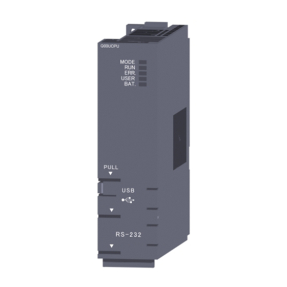
Page 135: Led Display
7 FUNCTION MELSEC-Q 7.16 LED Display The LEDs that indicate the operation statuses of the Basic model QCPU are provided on the front panel of the Basic model QCPU. The indications of the LEDs are described below. (1) The details of the LED display are shown below: LED name Display Description Indicates Basic model QCPU operation status. - Page 136 7 FUNCTION MELSEC-Q (2) How to turn off the ERR. LED To turn off the ERR. LED that is on, remove the cause of the error and then operate the special relay SM50 and special register SD50 to cancel the error. (This does not apply to reset operation.) REMARK Refer to Section 7.12.2 for canceling the error.
-
Page 137: Serial Communication Function (Usable With The Q00Cpu Or Q01Cpu)
7 FUNCTION MELSEC-Q 7.17 Serial Communication Function (Usable with the Q00CPU or Q01CPU) The serial communication function is designed to make communication in the MC protocol (*1) by connecting the RS-232 interface of the CPU module and personal computer, display device or the like by an RS-232 cable. The serial communication function is not used for connection of GX Developer or GX Configurator and the CPU module. - Page 138 7 FUNCTION MELSEC-Q (1) Specifications Transmission specifications The following table indicates the transmission specifications of RS-232 used for the serial communication function of the CPU module. Use the serial communication function after making sure that the specifications of the personal computer, Display device or the like match those of the following table.
- Page 139 7 FUNCTION MELSEC-Q RS-232 connector specifications The following table indicates the applications of the RS-232 connector of the Q00CPU/Q01CPU. Appearance Pin No. Signal Symbol Signal Name RD (RXD) Receive data SD (TXD) Send data Signal ground Mini-Din 6 pins DSR (DR) Data set ready (female)
- Page 140 7 FUNCTION MELSEC-Q (2) Functions The serial communication function allows the MC protocol commands in the following table to be executed. Refer to the following manual for details of the MC protocol. • Q-Compatible MELSEC Communication Protocol Reference Manual Function Command Processing Processing Points...
- Page 141 7 FUNCTION MELSEC-Q (3) Accessible devices Device Number Class Device Device Code Range Write Read (Default Value) Internal system Function input 000000 to 00000F device Function output 000000 to 00000F Function register 000000 to 000004 Special relay 000000 to 001023 Special register 000000 to 001023 Internal user...
- Page 142 7 FUNCTION MELSEC-Q (4) Setting of transmission specifications Use the serial communication setting PLC parameters to set the transmission speed, sum check, transmission wait time and write during RUN setting of the serial communication function. (a) When using the serial communication function to make communication with the personal computer, Display device or the like, specify "Use serial communication".
- Page 143 7 FUNCTION MELSEC-Q (6) Error codes for communication made using serial communication function The following table indicates the error codes, error definitions and corrective actions that are sent from the Q00CPU or Q01CPU to the external device when errors occur during communication made using the serial communication function.
- Page 144 7 FUNCTION MELSEC-Q Error Code Error Item Error Definition Corrective Action (Hexadecimal) • The command or device specified does • Check and correct the sent message of the 7F22H Command error not exist. device on the other end and restart •...
-
Page 145: Communication With Intelligent Function Module
8 COMMUNICATION WITH INTELLIGENT FUNCTION MODULE MELSEC-Q 8 COMMUNICATION WITH INTELLIGENT FUNCTION MODULE (1) Description of intelligent function modules Basic model QCPU allows the use of the Q series-compatible intelligent function modules. The intelligent function module is a module that allows Basic model QCPU to process analog values or high-speed pulses which cannot be processed with I/O modules. -
Page 146: Initial Setting And Automatic Refresh Setting Using Gx Configurator
8 COMMUNICATION WITH INTELLIGENT FUNCTION MODULE MELSEC-Q 8.2 Initial setting and automatic refresh setting using GX Configurator (1) Initial and automatic refresh settings of intelligent function modules Installing the GX Configurator compatible with the intelligent function module enables the initial setting and automatic refresh setting with GX Developer. When the initial setting and automatic refresh setting of the intelligent function module is designated with GX Developer, you can write/read data without creating the program for the communication with the intelligent function module. - Page 147 8 COMMUNICATION WITH INTELLIGENT FUNCTION MODULE MELSEC-Q (b) Automatic refresh setting For the automatic refresh setting, designate the device at Basic model QCPU to store the following data. • Digital output of Q64AD • Maximum/minimum values of Q64AD • Error code The automatic refresh setting of Q64AD is designated on the following automatic refresh setting screen of GX Configurator.
-
Page 148: Communication Using The Intelligent Function Module Device
8 COMMUNICATION WITH INTELLIGENT FUNCTION MODULE MELSEC-Q 8.3 Communication Using The Intelligent Function Module Device (1) Intelligent function module device The intelligent function module device is the buffer memory of the intelligent function module represented as a device of Basic model QCPU program. It enables reading data stored in the buffer memory of the intelligent function module, or enables writing data to the buffer memory of the intelligent function module. -
Page 149: Communication Using The Instructions Dedicated For Intelligent Function Modules
8 COMMUNICATION WITH INTELLIGENT FUNCTION MODULE MELSEC-Q 8.4 Communication Using The Instructions Dedicated for Intelligent Function Modules (1) Description of the instructions dedicated for intelligent function modules The instructions dedicated for intelligent function modules are the instructions that facilitate programming using the functions of the intelligent function modules. -
Page 150: Communication Using From/To Instruction
8 COMMUNICATION WITH INTELLIGENT FUNCTION MODULE MELSEC-Q 8.5 Communication Using FROM/TO Instruction (1) FROM/TO instruction At the execution of the FROM/TO instruction, the data stored in the buffer memory of the intelligent function module can be read, or data can be written to the buffer memory of the intelligent function module. -
Page 151: Parameter List
9 PARAMETER LIST MELSEC-Q 9 PARAMETER LIST There are two types of promoters used in Basic model QCPU's procedures: "PLC parameters" that are used when operating a PLC and "network parameters" that are used when connecting to the MELSECNET/H, Ethernet or CC-Link system. This chapter shows a listing of PLC parameters and network parameters used for GX Developer. - Page 152 9 PARAMETER LIST MELSEC-Q MEMO 9 - 2 9 - 2...
- Page 153 9 PARAMETER LIST MELSEC-Q Table 9.1 Parameter List Item Description Designate the label and comment for the CPU module to be used. PLC name settings These settings do not affect CPU module operation Label Designates the label setting (name and use). Comment Designates the comment setting.
- Page 154 9 PARAMETER LIST MELSEC-Q Default Value Setting Range Reference Section — — — No setting Max. of 10 characters — No setting Max. of 64 characters — — — — 100 ms 1 ms to 1000 ms(1 ms units) Section 10.2.10 10.0 ms 0.1 ms to 100.0 ms Section 10.2.10...
- Page 155 9 PARAMETER LIST MELSEC-Q Table 9.1 Parameter List (continued) Item Description These settings designate the number of points for each device, the latch range, Device settings and the local device range. Number of device points Designates the number of device points used. Latch (1) first/last Set the latch range where data can be cleared by remote latch clear operation (Latch clear valid)
- Page 156 9 PARAMETER LIST MELSEC-Q Default Value Setting Range Reference Section — — — X: 8 k points Y: 8 k points M: 8 k points L: 8 k points X(2 k points), Y(2 k points), S(2 k points), SB(1k points) and B: 8 k points SW(1 k points) are fixed.
- Page 157 9 PARAMETER LIST MELSEC-Q Table 9.1 Parameter List (continued) Item Description Enables the user to check I/O assignments, MELSECNET/ETHERNET settings, X/Y allocation check and CC-Link settings. Set the transmission speed, sum check, message wait time and write during RUN Serial communication setting enable/disable when using the serial communication function of Q00/Q01CPU.
- Page 158 9 PARAMETER LIST MELSEC-Q Default Value Setting Range Reference Section — — — — — — — — — 19.2kbps 9.6 kbps/19.2 kbps/38.4 kbps/57.6 kbps/115.2 kbps No/Yes Section 7.17 No wait No wait/10ms to 150ms (10ms increments) Not enabled Not enabled/Enabled —...
-
Page 159: Devices
10 DEVICES MELSEC-Q 10 DEVICES This chapter describes all devices that can be used in Basic model QCPU. 10.1 Device List The names and data ranges of devices which can be used in Basic model QCPU are shown in Table 10.1 below. Table 10.1 Device List Default Values Parameter... - Page 160 10 DEVICES MELSEC-Q Default Values Parameter Reference Class Type Device Name Designated Number of Points Range Used Section Setting Range Link input 8192 points Jn\X0 to Jn\X1FFF Link output 8192 points Jn\Y0 to Jn\Y1FFF Bit device Link direct Link relay 16384 points Jn\B0 to Jn\B3FFF Impossible...
-
Page 161: Internal User Devices
10 DEVICES MELSEC-Q 10.2 Internal User Devices Internal user devices can be used for various user applications. The "number of usable points" setting is designated in advance (default value) for internal user devices. However, this setting can be changed by PLC parameter device setting. [Device setting screen] Default value "Dev. - Page 162 10 DEVICES MELSEC-Q For timer (T) retentive timer (ST), and Counter (C): For the timer, retentive timer, and counter, 16 points are calculated as 18 words. (T, ST, C total number of points) 18 (Word) (Timer, retentive, counter size) = For word devices: For data registers (D) and link registers (W), 16 points are calculated as 16 words.
-
Page 163: Inputs (X)
10 DEVICES MELSEC-Q 10.2.1 Inputs (X) (1) Definition Inputs are commands or data transmitted to the Basic model QCPU from a peripheral device by push-button switches, selector switches, limit switches, digital switches, etc. Push-button switch Selector switch Input (X) Sequence operation Digital switch The input point is the Xn virtual relay inside the Basic model QCPU, with the... - Page 164 10 DEVICES MELSEC-Q (2) Reading the inputs There are 2 types of input: "refresh inputs" and "direct access inputs". Refresh inputs are ON/OFF data read from the input module using the refresh mode. CPU module Input module Acquisition of ON/OFF data Input refresh area ON/OFF data...
- Page 165 10 DEVICES MELSEC-Q The same input number can be designated for a refresh input and a direct access input. If used as a refresh input after being used as a direct access input, operation will be based on the ON/OFF data read at the direct access input. Operation is based on the ON/OFF data read at the END processing input refresh.
-
Page 166: Outputs (Y)
10 DEVICES MELSEC-Q 10.2.2 Outputs (Y) (1) Definition Outputs are program control results which are output to external destinations (solenoid, electromagnetic switch, signal lamp, digital display, etc.). Signal lamp Digital display Output (Y) Sequence operation Contact Outputs occur at one N/O contact or its equivalent. There are no restrictions regarding the number of output Yn N/O contacts and N/C contacts used in a program. - Page 167 10 DEVICES MELSEC-Q (3) Output method There are 2 types of output: "refresh outputs" and "direct access outputs". Refresh outputs are ON/OFF data which is output to the output module using the refresh mode. Output module CPU module ON/OFF data output Output refresh area These outputs are indicated as "Y "...
-
Page 168: Internal Relays (M)
10 DEVICES MELSEC-Q 10.2.3 Internal relays (M) (1) Definition Internal relays are auxiliary relays which cannot be latched by the programmable controller's internal latch (memory backup). All internal relays are switched OFF at the following times: • When power is switched from OFF to ON. •... -
Page 169: Latch Relays (L)
10 DEVICES MELSEC-Q 10.2.4 Latch relays (L) (1) Definition (a) Latch relays are auxiliary relays which can be latched by the programmable controller's internal latch (memory backup). Latch relay operation results (ON/OFF information) are saved even in the following cases: •... -
Page 170: Anunciators (F)
10 DEVICES MELSEC-Q 10.2.5 Anunciators (F) (1) Definition Anunciators are internal relays used by the user in fault detection program. (b) When anunciators switch ON, a special relay (SM62) switches ON, and the Nos. and quantity of anunciators which switched ON are stored at the special registers (SD62 to SD79). - Page 171 10 DEVICES MELSEC-Q (2) Anunciator ON procedure Anunciator ON procedure Anunciator operation can be controlled by the SET F and OUT F instructions. The SET F instruction switches the anunciator ON only at the leading edge (OFF to ON) of the input condition, and keeps the anunciator ON when the input condition switches OFF.
- Page 172 10 DEVICES MELSEC-Q The OUT F instruction can execute ON/OFF of the anunciator No. by the same instruction. However, if an anunciator is switched OFF by the OUT F instruction, the "processing at anunciator OFF" (item (b) below) does not occur. Execute the RST F or BKRST instructions after the anunciator has been switched OFF by the OUT F...
- Page 173 10 DEVICES MELSEC-Q Processing at anunciator OFF Special register (SD62 to SD79) data operation when an anunciator is switched OFF by the RST F instruction • The anunciator No. which was switched OFF is deleted, and all subsequent anunciator Nos. are moved up to fill the vacant space. •...
-
Page 174: Edge Relay (V)
10 DEVICES MELSEC-Q 10.2.6 Edge relay (V) (1) Definition An edge relay is a device which stores the operation results (ON/OFF information) from the beginning of the ladder block. Edge relays can only be used at contacts, and cannot be used as coils. Edge relay Stores the X0, X1 and X10 operation results The same edge relay number cannot be used twice in program executed by... -
Page 175: Link Relays (B)
10 DEVICES MELSEC-Q 10.2.7 Link relays (B) (1) Definition A link relay is the Basic model QCPU relay used to refresh the Basic model QCPU from the MELSECNET/H network module's link relay (LB) and to refresh the MELSECNET/H network module's link relay (LB) from the Basic model QCPU data. -
Page 176: Special Link Relays (Sb)
10 DEVICES MELSEC-Q 10.2.8 Special link relays (SB) (1) Definition A special link relay indicates the communication status and error detection of an intelligent function module, such as the MELSECNET/10H Network Module. Because special link relays are switched ON and OFF in accordance with various problems which may occur during a data link, they serve as a tool for identifying data link problems. -
Page 177: Timers (T)
10 DEVICES MELSEC-Q 10.2.10 Timers (T) Timers are of a forward timer type, with the time measurement beginning when the coil switches ON, and ending (time out) when the present value exceeds the setting value. The present value matches the setting value when a "time-out" occurs. There are two types of timers: a low/high-speed that allows the current value to return to "0"... - Page 178 10 DEVICES MELSEC-Q High-speed timers (1) Definition High-speed timers are timers which are only operative while the coil is ON. A high-speed timer is marked with a symbol "H". The time measurement begins when the timer's coil switches ON, and the contact switches ON when the time elapses.
- Page 179 10 DEVICES MELSEC-Q Retentive timers (1) Definition Retentive timers measure the "coil ON" time. The measurement begins when the timer coil switches ON, and the contact switches ON when a time-out (coil OFF) occurs. Even when the timer coil is OFF, the present value and the contact ON/OFF status are saved.
- Page 180 10 DEVICES MELSEC-Q Timer Processing & accuracy (a) When an OUT T instruction is executed, the following processing occurs: timer coil ON/OFF, present value update & contact ON/OFF processing. Timer present value update and contact ON/OFF processing do not occur at END processing.
- Page 181 10 DEVICES MELSEC-Q The timer response accuracy from the point when input (X) reading occurs, until the point when the output occurs is + (2-scan time + timer time limit setting). Precautions when using timers The following are a few precautions regarding timer use: A given timer cannot be designated (by OUT T ) more than once in a single scan.
-
Page 182: Counters (C)
10 DEVICES MELSEC-Q 10.2.11 Counters (C) Counters are "up counter" types, with the contact being switched ON when the count value equals the setting value (count-out condition). There are two counter types: counters which count the number of input condition start- ups (leading edges) in sequence program, and counters which count the number of interrupt factor occurrences. - Page 183 10 DEVICES MELSEC-Q Multiple counters can be used within a single scan to achieve the maximum counting speed. In such cases, the direct access input (DX ) method should be used for the counter input signals. Sequence program OUT C execution intervals (3) Resetting the counter Counter present values are not cleared even if the OUT C...
- Page 184 10 DEVICES MELSEC-Q Interrupt counters (1) Definition Interrupt counters are devices which count the number of interrupt factor occurrences. (2) Count processing The interrupt counter's present value is updated when an interruption occurs. It is not necessary to create a program which includes an interrupt counter function.
- Page 185 10 DEVICES MELSEC-Q (4) Precautions One interrupt pointer is insufficient to execute interrupt counter and interrupt program operation. Moreover, an interrupt program cannot be executed by an interrupt counter setting designated in the PLC system settings in the PLC parameter setting. If the processing items shown below are in progress when an interruption occurs, the counting operation will be delayed until processing of these items is completed.
-
Page 186: Data Registers (D)
10 DEVICES MELSEC-Q 10.2.12 Data registers (D) (1) Definition Data registers are memory devices which store numeric data (-32768 to 32767, or 0000 to FFFF Data registers consist of 16 bits per point, with reading and writing executed in 16-bit units. If the data registers are used for 32-bit instructions, the data will be stored in registers Dn and Dn + 1. -
Page 187: Link Registers (W)
10 DEVICES MELSEC-Q 10.2.13 Link registers (W) (1) Definition A link register is the Basic model QCPU memory used to refresh the Basic model QCPU with data from the link registers (LW) of intelligent function modules including MELSECNET/H network module. Link registers are used to store numeric data (-32768 to 32767, or 0000 FFFF Basic model QCPU... -
Page 188: Special Link Registers (Sw)
10 DEVICES MELSEC-Q (2) Using link registers in a network system In order to use link registers in the network system, network parameter settings must be made. Link registers not set in the network parameter settings can be used as data registers. -
Page 189: Internal System Devices
10 DEVICES MELSEC-Q 10.3 Internal System Devices Internal system devices are devices used for system operations. The allocations and sizes of internal system devices are fixed, and cannot be changed by the user. 10.3.1 Function devices (FX, FY, FD) (1) Definition Function devices are devices used in sub-routine program with arguments to permit data transfers between the sub-routine program with argument, and the CALL source for that sub-routine. - Page 190 10 DEVICES MELSEC-Q Function registers • Function registers are used to designate data transfers between the sub- routine CALL source and the sub-routine program. • The function register input/output condition is automatically determined by the Basic model QCPU. If the sub-routine program data is the source data, the data is designated as sub-routine input data.
-
Page 191: Special Relays (Sm)
10 DEVICES MELSEC-Q 10.3.2 Special relays (SM) (1) Definition (a) A special relay is used to store High Performance model QCPU status data. (2) Special relay classifications Special relays are classified according to their applications, as shown below. (a) For fault diagnosis : SM0 to SM99 (b) For serial communication function : SM100 to SM129 (c) System information... -
Page 192: Special Registers (Sd)
10 DEVICES MELSEC-Q 10.3.3 Special registers (SD) (1) Definition A special register is used to store Basic model QCPU status data (diagnosis and system information). (2) Special register classifications Special registers are classified according to their applications, as shown below. For fault diagnosis : SD0 to SD99 (b) For serial communication function : SM100 to SM129... -
Page 193: Link Direct Devices (J \ )
10 DEVICES MELSEC-Q 10.4 Link Direct Devices (J \ ) (1) Definition At END processing, a data refresh (data transfer) operation occurs between the Basic model QCPU and the MELSECNET/H network system modules. Link direct devices are used at that time to directly access the link devices in the MELSECNET/H network modules. - Page 194 10 DEVICES MELSEC-Q Although writing is also possible in the "refresh range" portion of the link device range (specified by the refresh parameters), the link module's link device data will be rewritten when a refresh operation occurs. Therefore, when writing by link direct device, the same data should also be written to the Basic model QCPU related devices designated by the refresh parameters.
- Page 195 10 DEVICES MELSEC-Q (3) Differences between "link direct devices" and "link refresh" The differences between "link direct devices" and "link refresh" are shown in Table 10.4 below. Table 10.4 Differences Between "Link Direct Devices" and "Link Refresh" Item Link Direct Device Link Refresh Link relay J \K4B0 or later...
-
Page 196: Intelligent Function Module Devices (U \G )
10 DEVICES MELSEC-Q 10.5 Intelligent Function Module Devices (U \G ) (1) Definition The intelligent function module devices allow the Basic model QCPU to directly access the buffer memories of intelligent function modules which are installed at the base unit. Intelligent function module devices are designated by the intelligent function module input/ output No., and the buffer memory address. -
Page 197: Index Registers (Z)
10 DEVICES MELSEC-Q 10.6 Index Registers (Z) (1) Definition Index registers are used in the sequence program for indirect setting (index qualification) designations. An index register point is used for index modification. MOVP K5 Z0 SM400 D0Z0 K4Y30 Index registers consist of 16 bits per point. There are 10 index registers (Z0 to Z9). -
Page 198: Switching Between Main Routine/Sub-Routine Program And Interrupt Program
10 DEVICES MELSEC-Q 10.6.1 Switching between main routine/sub-routine program and interrupt program The PLC System sheet of the PLC Parameter dialog box provides the option to save (protect) or restore index register data (Z0 to Z9) when switching between main routine/sub-routine program and a low-speed execution type program or between an interrupt program. - Page 199 10 DEVICES MELSEC-Q (2) When the "High-speed execution" check box is ON: If a main routine/sub-routine program is switched to an interrupt program, index register data will not be saved/restored. If data is written onto index registers by using an interrupt program, the values of index registers used for an main routine/sub-routine program will be corrupted.
-
Page 200: File Registers (R)
10 DEVICES MELSEC-Q 10.7 File Registers (R) (1) Definition File registers are expansion devices for data registers. File register data is stored in files in the CPU standard RAM. The standard RAM has 32k points assigned for file registers. File registers can be used at the same processing speed as data registers. - Page 201 10 DEVICES MELSEC-Q (2) Precautions for use of file registers Performing write/read to/from 32k or more points of file register numbers will not result in an error. However, note that performing read from file registers will store indefinite data. (3) File register deletion File registers can be deleted by performing online PLC data deletion.
-
Page 202: Nesting (N)
10 DEVICES MELSEC-Q 10.8 Nesting (N) (1) Definition Nesting devices are used to nest MC or MCR master control instructions when programming operating conditions. (2) Designation method with master control The master control instructions are used to open and close the ladders' common bus so that switching of ladders may be executed efficiently by the sequence program. -
Page 203: Pointers (P)
10 DEVICES MELSEC-Q 10.9 Pointers (1) Definition Pointer devices are used in jump instructions (CJ, SCJ, JUMP) or sub-routine call instructions (CALL, ECALL). A total of 300 pointers can be used. (2) Pointer applications Pointers are used in jump instructions (CJ, SCJ, JMP) to designate jump destinations and labels (jump destination beginning). -
Page 204: Interrupt Pointers (I)
10 DEVICES MELSEC-Q 10.10 Interrupt Pointers (I) (1) Definition Interrupt pointers are used as labels at the beginning of interrupt program. Interrupt pointer (interrupt program label) Interrupt program IRET A total of 128 interrupt points (I0 to I127) can be used. (2) Interrupt pointer No. - Page 205 10 DEVICES MELSEC-Q A list of interrupt pointer Nos. and interrupt factors is given in Table 10.5 below. Table 10.5 List of Interrupt Pointer Nos. and Interrupt Factors Priority I No. Interrupt Factors Ranking 1st point 2nd point 3rd point 4th point 5th point 6th point...
-
Page 206: Other Devices
10 DEVICES MELSEC-Q 10.11 Other Devices 10.11.1 Network No. designation device (J) (1) Definition The network No. designation device is used to designate the network No. in data link instructions. (2) Designating network No. designation device The network No. designation device is designated in the data link instruction as shown below. -
Page 207: Macro Instruction Argument Device (Vd)
10 DEVICES MELSEC-Q 10.11.3 Macro instruction argument device (VD) (1) Definition Macro instruction argument devices are used with ladders registered as macros. When a VD setting is designated for a ladder registered as a macro, conversion to the designated device occurs when the macro instruction is executed. -
Page 208: Constants
10 DEVICES MELSEC-Q 10.12 Constants 10.12.1 Decimal constants (K) (1) Definition Decimal constants are devices which designate decimal data in sequence program. They are designated as "K "settings (e.g. K1234), and are stored in the Basic model QCPU in binary (BIN) code. See Section 4.8.1 for details regarding binary code. -
Page 209: Processing Times Of The Basic Model Qcpu
11 PROCESSING TIMES OF THE BASIC MODEL QCPU MELSEC-Q 11 PROCESSING TIMES OF THE BASIC MODEL QCPU This chapter describes the concept of the processing times of the Basic model QCPU. 11.1 Scan Time Structure In the RUN status, the Basic model QCPU performs the following processings cyclically. -
Page 210: Concept Of Scan Time
11 PROCESSING TIMES OF THE BASIC MODEL QCPU MELSEC-Q 11.2 Concept of Scan Time The scan time varies with the following elements. • Number of I/O points • Processing times of all instructions executed within one scan • Sum of processing times of user interrupt program executed within one scan •... - Page 211 11 PROCESSING TIMES OF THE BASIC MODEL QCPU MELSEC-Q (3) Instruction execution time (a) Sum of the processing times of the instructions used in the program executed by the Basic model QCPU. Refer to the following manual for the processing times of the corresponding instructions.
- Page 212 11 PROCESSING TIMES OF THE BASIC MODEL QCPU MELSEC-Q 3) As KN1 and KN2, use the values in the following table. When the intelligent module is installed on the main base unit KN1 ( 10 KN2 ( 10 CPU Type Q00JCPU Q00CPU Q01CPU...
-
Page 213: Other Processing Times
11 PROCESSING TIMES OF THE BASIC MODEL QCPU MELSEC-Q (6) Service processing time (a) Monitoring using GX Developer Processing time (unit: ms) for monitoring using GX Developer. Added when monitoring is performed on GX Developer. When Connected to RS-232 of Host CPU When Connected to Other Station Module Function... -
Page 214: Procedure For Writing Programs To Basic Model Qcpu
12 PROCEDURE FOR WRITING PROGRAMS TO BASIC MODEL QCPU MELSEC-Q 12 PROCEDURE FOR WRITING PROGRAM TO BASIC MODEL QCPU This chapter describes the procedure for writing program created at the GX Developer to the Basic model QCPU. 12.1 Items to Consider when Creating Program In order to create a program, the program size, number of device points used, and the program file name, etc., must be set in advance. -
Page 215: Procedure For Writing Program To The Basic Model Qcpu
12 PROCEDURE FOR WRITING PROGRAMS TO BASIC MODEL QCPU MELSEC-Q 12.2 Procedure for writing program to the Basic model QCPU The procedure for writing program and parameter created at the GX Developer to the Basic model QCPU standard ROM is shown below. When writing program and parameter to the Basic model QCPU program memory, the steps indicated by asterisks ( ) below are not required. - Page 216 12 PROCEDURE FOR WRITING PROGRAMS TO BASIC MODEL QCPU MELSEC-Q Refer to the GX Developer manual. Connect GX Developer and CPU module. ERR. LED is lit. Move the RUN/STOP/RESET switch of the CPU module to the STOP position and switch power on.
-
Page 217: Appendices
APPENDICES MELSEC-Q APPENDICES APPENDIX 1 Special Relay List Special relays, SM, are internal relays whose applications are fixed in the programmable controller. For this reason, they cannot be used by sequence programs in the same way as the normal internal relays. However, they can be turned ON or OFF as needed in order to control the CPU and remote I/O modules. -
Page 218: Appendix 1 Special Relay List
APPENDICES MELSEC-Q Special Relay List (1) Diagnostic Information Number Name Meaning Explanation Set by (When Set) • ON if diagnosis results show error occurrence OFF: No error Diagnostic errors (Includes external diagnosis) S (Error) ON : Error • Stays ON subsequently even if normal operations restored OFF: No self-diagnosis Self-diagnostic •... - Page 219 APPENDICES MELSEC-Q Special Relay List (2) System information Number Name Meaning Explanation Set by (When Set) SM203 STOP contact STOP state • Goes ON at STOP state S (Status change) SM204 PAUSE contact PAUSE state • Goes ON at PAUSE state S (Status change) PAUSE enable OFF: PAUSE disabled...
- Page 220 APPENDICES MELSEC-Q Special Relay List (4) Memory cards Number Name Meaning Explanation Set by (When Set) Memory card B OFF: Unusable SM620 • Always ON S (Initial) usable flags ON : Use enabled Memory card B OFF: No protect SM621 •...
-
Page 221: Appendix 2 Special Register List
APPENDICES MELSEC-Q APPENDIX 2 Special Register List The special registers, SD, are internal registers with fixed applications in the programmable controller. For this reason, it is not possible to use these registers in sequence programs in the same way that normal registers are used. However, data can be written as needed in order to control the CPU module. - Page 222 APPENDICES MELSEC-Q Special Register List (1) Diagnostic Information Number Name Meaning Explanation Set by (When set) • Error codes for errors found by diagnosis are stored as BIN data. Diagnostic errors Diagnosis error code S (Error) • Contents identical to latest fault history information. •...
- Page 223 APPENDICES MELSEC-Q Special Register List (Continued) Number Name Meaning Explanation Set by (When set) • Common information corresponding to the error codes (SD0) is stored here. • The following four types of information are stored here: Slot No. Meaning Number Slot No./Base No.
- Page 224 APPENDICES MELSEC-Q Special Register List (Continued) Number Name Meaning Explanation Set by (When set) • Individual information corresponding to error codes (SD0) is stored here. File name/Drive name SD16 (Example) File name= Number Meaning MAIN. QPG SD16 Drive B15 to B8 B7 to B0 SD17 SD17 SD18...
- Page 225 APPENDICES MELSEC-Q Special Register List (Continued) Number Name Meaning Explanation Set by (When set) Error number that • Stores error number that performs error reset SD50 Error reset performs error reset • All corresponding bits go ON when battery voltage drops. •...
- Page 226 APPENDICES MELSEC-Q Special Register List (Continued) Number Name Meaning Explanation Set by (When set) Stores the Transmission transmission speed K96: 9.6kbps, K192: 19.2kbps, K384: 38.4kbps, SD100 speed storage specified in the serial S (Power-on or reset) K576: 57.6kbps, K1152: 115.2kbps area communication setting.
- Page 227 APPENDICES MELSEC-Q Special Register List (2) System information Number Name Meaning Explanation Set by (When set) • The CPU switch status is stored in the following format: B8 B7 B4 B3 S(Every END Vacant SD200 State of switch State of CPU switch processing) : CPU switch status 0: RUN...
- Page 228 APPENDICES MELSEC-Q Special Register List (Continued) Number Name Meaning Explanation Set by (When set) • Stores the message (16 characters of ASCII data) at error occurrence (including SD220 annunciator ON). SD221 SD222 SD220 15th character from the right 16th character from the right SD221 13th character from the right 14th character from the right...
- Page 229 APPENDICES MELSEC-Q Special Register List (Continued) Number Name Meaning Explanation Set by (When set) Number of points SD299 • Stores the number of points currently set for T device Device allocated for T allocation Number of points SD300 (Same as •...
- Page 230 APPENDICES MELSEC-Q (4) Scan information Number Name Meaning Explanation Set by (When set) Current scan time • Stores current scan time (in 1 ms units) S (Every END SD520 (in 1 ms units) Range from 0 to 65535 processing) • Stores current scan time (in 100 µs units) Current scan Range from 00000 to 900 time...
- Page 231 APPENDICES MELSEC-Q (5) Memory card Number Name Meaning Explanation Set by (When set) • Indicates memory card B models installed B8 B7 B4 B3 0< ----------- >0 Drive 3 0: Absent Memory card B Memory card B SD620 S (Initial) (Standard RAM) 1: Present models...
- Page 232 APPENDICES MELSEC-Q APPENDIX 3 List of Interrupt Pointer Nos. and Interrupt Factors Priority I No. Interrupt Factors Ranking 1st point 2nd point 3rd point 4th point 5th point 6th point 7th point 8th point QI60 interrupt module factor 9th point 10th point 11th point 12th point...
- Page 233 APPENDICES MELSEC-Q MEMO App - 17 App - 17...
-
Page 234: Index
INDEX Accuracy of scan time ......... 4-9 FY (Function output) ........10-31 Annunciator (F) ........10-12 ASCII code..........4-25 Auto mode ..........5- 3 GX Configurator ..........8- 2 GX Developer ..........A-17 Base mode..........5- 4 BCD (Binary coded decimal)..... 4-24 H (Hexadecimal constants) ......10-50 BIN (Binary code) ........ - Page 235 List of Interrupt factors ........ 10-47 Scan time ............4- 9 App-10 SD (Special register)........10-34 Low-speed retentive timer (ST) ....10-21 SD520, SD521 (Scan time: present value)..4- 9 Low-speed timer (T) ........ 10-19 SD524, SD525 (Scan time: Maximum value) ..4- 9 SD526, SD527 (Scan time: Minimum value) ..4- 9 M (Internal relay) .........
- Page 236 WARRANTY Please confirm the following product warranty details before starting use. 1. Gratis Warranty Term and Gratis Warranty Range If any faults or defects (hereinafter "Failure") found to be the responsibility of Mitsubishi occurs during use of the product within the gratis warranty term, the product shall be repaired at no cost via the dealer or Mitsubishi Service Company. Note that if repairs are required at a site overseas, on a detached island or remote place, expenses to dispatch an engineer shall be charged for.
- Page 237 Microsoft Windows, Microsoft Windows NT are registered trademarks of Microsoft Corporation in the United States and other countries. Pentium is a registered trademark of Intel Corporation in the United States and other countries. Ethernet is a registered trademark of Xerox. Co., Ltd in the United States. Other company and product names herein are either trademarks or registered trademarks of their respective owners.
- Page 238 Basic Model QCPU(Q Mode) User's Manual (Function Explanation, Program Fundamentals) SQCPU(Q)-U-KI-E MODEL MODEL 13JR44 CODE SH(NA)-080188-A(0108)MEE HEAD OFFICE : 1-8-12, OFFICE TOWER Z 14F HARUMI CHUO-KU 104-6212,JAPAN NAGOYA WORKS : 1-14 , YADA-MINAMI 5 , HIGASHI-KU, NAGOYA , JAPAN When exported from Japan, this manual does not require application to the Ministry of Economy, Trade and Industry for service transaction permission.
Need help?
Do you have a question about the MELSEC-Q Series and is the answer not in the manual?
Questions and answers