
Related Manuals for Mitsubishi Electric QJ71E71-100


Summary of Contents for Mitsubishi Electric QJ71E71-100
- Page 1 Q Corresponding Ethernet Interface Module User's Manual (Basic) -QJ71E71-100 -QJ71E71-B5 -QJ71E71-B2...
-
Page 3: Safety Precautions
SAFETY PRECAUTIONS (Read these precautions before using this product.) Before using this product, please read this manual and the relevant manuals carefully and pay full attention to safety to handle the product correctly. In this manual, the safety precautions are classified into two levels: " WARNING"... - Page 4 [Design Precautions] WARNING ● For the operating status of each station after a communication failure, refer to manuals relevant to the network. Incorrect output or malfunction due to a communication failure may result in an accident. ● To prevent the malfunction of the programmable controller system due to harmful e-mails, take preventive measures (such as antivirus measures) so that the mail server for this module does not receive harmful e-mails.
- Page 5 [Installation Precautions] CAUTION ● Use the programmable controller in an environment that meets the general specifications in the user's manual for the CPU module used. Using the programmable controller in any other operating environments may cause electric shocks, fires or malfunctions, or may damage or degrade the module.
- Page 6 [Setup and Maintenance Precautions] WARNING ● Do not touch any terminal while power is on. Doing so will cause electric shock or malfunction. ● Shut off the external power supply (all phases) used in the system before cleaning the module or retightening the terminal screws, connector screws, or module fixing screws.
-
Page 7: Conditions Of Use For The Product
CONDITIONS OF USE FOR THE PRODUCT (1) Mitsubishi programmable controller ("the PRODUCT") shall be used in conditions; i) where any problem, fault or failure occurring in the PRODUCT, if any, shall not lead to any major or serious accident; ii) where the backup and fail-safe function are systematically or automatically provided outside of the PRODUCT for the case of any problem, fault or failure occurring in the PRODUCT. -
Page 8: Introduction
Ethernet interface modules: QJ71E71-100, QJ71E71-B5, and QJ71E71-B2 (hereafter referred to as E71). Before using this product, please read this manual and the relevant manuals carefully and develop familiarity with the functions and performance of the MELSEC-Q series programmable controller to handle the product correctly. -
Page 9: Relevant Manuals
RELEVANT MANUALS This manual describes the basic specifications, functions, and usage of the E71. (1) E71 relevant manual Manual name Description <manual number, model code> MELSEC-Q/L Ethernet Interface Module User's E-mail function, communication function (communications via CC-Link IE Manual (Application) Controller Network, CC-Link IE Field Network, MELSECNET/H, or MELSECNET/10, and communications by using the data link instructions), and file <SH-080010, 13JL89>... -
Page 10: Table Of Contents
Wiring with the QJ71E71-100 ........ - Page 11 CHAPTER 7 COMMUNICATION PROCEDURE Setting Parameters Required for Communications ....... . . 7.1.1 Parameter list .
- Page 12 CHAPTER 12 COMMUNICATIONS USING A FIXED BUFFER 12.1 Applications ............. . 12.1.1 Differences between the "Procedure Exist"...
- Page 13 14.2.1 Application ............. . 14.3 IP Filter Function.
- Page 14 16.4.2 If the ERR. LED or COM.ERR. LED turns on ........16.4.3 If the SD LED does not flash when data is sent .
- Page 15 ....... 386 Appendix 8.3 Data examples of packet elements Appendix 9 Usage example of MX Component .........
-
Page 16: Manual Page Organization
MANUAL PAGE ORGANIZATION In this manual, pages are organized and the symbols are used as shown below. The following illustration is for explanation purpose only, and should not be referred to as an actual documentation. "" is used for window names and items. -
Page 17: Term
Built-in Ethernet port QCPU Q06UDVCPU, Q06UDEHCPU, Q10UDEHCPU, Q13UDVCPU, Q13UDEHCPU, Q20UDEHCPU, Q26UDVCPU, Q26UDEHCPU, Q50UDEHCPU, and Q100UDEHCPU A generic term for the Ethernet interface modules: QJ71E71-100, QJ71E71-B5, and QJ71E71-B2 E71-mounted station The abbreviation for the station where the E71 is mounted The abbreviation for File Transfer Protocol. This protocol is used to transfer data files over a network. - Page 18 Term Description A generic term for the partner products with built-in EZSocket that supports a redundant system. The E71 communicates with an OPS using a connection specified by a user. The abbreviation for Post Office Protocol Ver.3. This protocol is used to transfer e-mails from a POP3 mail server to a local computer.
-
Page 19: Packing List
PACKING LIST The following items are included in the package of this product. Before use, check that all the items are included. QJ71E71-100 QJ71E71-100 Before Using the Product QJ71E71-B5 QJ71E71-B5 Before Using the Product... - Page 20 QJ71E71-B2 QJ71E71-B2 Before Using the Product...
-
Page 21: Chapter 1 Features
CHAPTER 1 FEATURES CHAPTER 1 FEATURES An Ethernet module (hereafter abbreviated as E71) is an interface module on the programmable controller side for connecting a programmable controller system to the host system, such as a personal computer and a workstation, over Ethernet. - Page 22 (1) Connection with MELSOFT products and a GOT In Ethernet, a programming tool can create programming of a programmable controller and monitor a programmable controller (MELSOFT connection), and the GOT can monitor and test a programmable controller. Remote operations making full use of the Ethernet capability, long-distance connectivity and high-speed communications, are achieved.
- Page 23 CHAPTER 1 FEATURES (4) Data communications using the predefined protocol (predefined protocol support function) Registering protocol data in advance using GX Works2 allows communications by executing only an ECPRTCL instruction program. In addition, the protocol setting required to communicate with the connected device, such as a measuring instrument or a bar code reader, can be configured easily using the Predefined Protocol Support Function of GX Works2.
- Page 24 (5) Exchange of data with connected devices (communications using a fixed buffer and random access buffer) (a) Communications using a fixed buffer Up to 1K-word data can be exchanged among programmable controllers or between a programmable controller and the host system. While MC protocol communications are passive, communications using a fixed buffer are an active protocol.
- Page 25 CHAPTER 1 FEATURES (8) E-mail sending/receiving (e-mail function) This function sends and receives e-mails to and from a connected device in a remote location via the Internet. For details, refer to the following. MELSEC-Q/L Ethernet Interface Module User's Manual (Application) (a) E-mail sending/receiving through the CPU module The following data can be sent and received using the MSEND/MRECV instructions.
- Page 26 (9) Data sending/receiving using the Web function The system administrator can monitor a CPU module in a remote location via the Internet using a commercially available Web browser. For details, refer to the following. MELSEC-Q/L Ethernet Interface Module User's Manual (Web function) HTTP MC protocol header...
-
Page 27: Chapter 2 Part Names
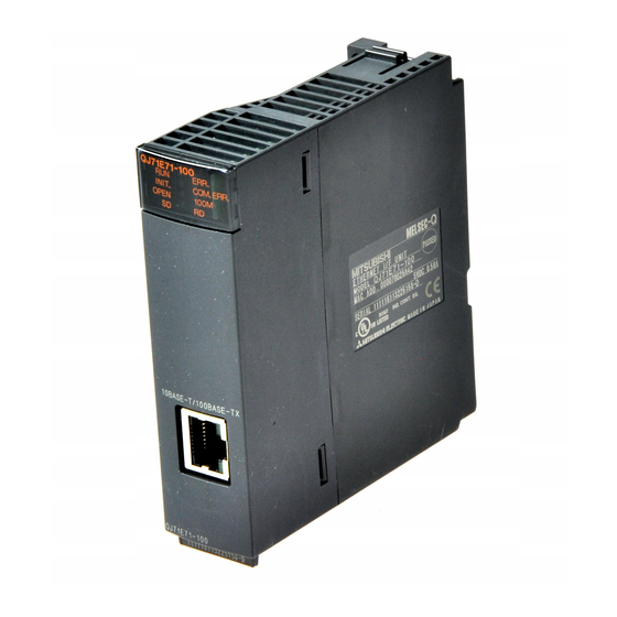
CHAPTER 2 PART NAMES CHAPTER 2 PART NAMES This chapter describes the E71 parts. Name Application LED indicator Refer to (1) in this chapter. 10BASE-T/100BASE-TX connector A connector to connect the E71 to the 10BASE-T or 100BASE-TX network (The E71 determines whether to use 10BASE-T or 100BASE-TX according to the hub.) (RJ45) A connector to connect the E71 to the 10BASE5 network (for connecting a 10BASE5 AUI... - Page 28 (1) LED indication QJ71E71-100 QJ71E71-B5 QJ71E71-B2 ERR. ERR. ERR. INIT. COM.ERR. INIT. COM.ERR. INIT. COM.ERR. OPEN 100M OPEN OPEN LED name Description Indicates operating status. In normal operation An error has occurred. ( Page 285, Section 16.4.1) INIT. Indicates initial process status.
-
Page 29: Chapter 3 Specifications
CHAPTER 3 SPECIFICATIONS CHAPTER 3 SPECIFICATIONS This chapter describes the performance specifications, functions, CPU module I/O signals, and buffer memory areas of an E71. General Specifications For the general specifications of an E71, refer to the following. "Safety Guidelines", the manual included with the CPU module or base unit... -
Page 30: Performance Specifications
Performance Specifications The following table lists the performance specifications of an E71. Specifications Item QJ71E71-100 QJ71E71-B5 QJ71E71-B2 100BASE-TX 10BASE-T 10BASE5 10BASE2 100Mbps Data transmission speed (Full-duplex/Half- 10Mbps (Half-duplex) duplex) Full-duplex: None Half-duplex: Back Flow control Back pressure congestion control (Half-duplex) - Page 31 Transceiver Node Terminating resistor Repeater Repeater Node Node Maximum node-to-node distance Node Node For the maximum segment length (the length between hubs), consult the manufacturer of the hub used. The QJ71E71-100 does not support the flow control of the IEEE802.3x.
-
Page 32: Function List
Hub connection status monitor The current connection status and transmission speed of an E71 and a hub and the Page 210, function (only QJ71E71-100) number of times that the E71 detected disconnection can be checked. Section 14.5 IP address in use detection function... - Page 33 Module error collection function history. The history data can be stored on a memory with the backup power feature; Page 284, (only QJ71E71-100) therefore error details are held even if the CPU module is reset or the system is Section 16.3...
- Page 34 (2) Special functions The following special functions are also available. For the functions, refer to the following. MELSEC-Q/L Ethernet Interface Module User's Manual (Application) Function Description Data are sent/received using an e-mail. • Data sent/received by a CPU module E-mail function •...
-
Page 35: Use With Other Functions
CHAPTER 3 SPECIFICATIONS 3.3.2 Use with other functions The following table lists the relationships between functions that can be used together. : Available, ×: Not available or this function does not correspond to the functions in the "Communication function" column. CC-Link IE Controller Communication Network, CC-Link IE Field... -
Page 36: List Of I/O Signals
List of I/O Signals The following table lists the I/O signals for an E71. The I/O signal assignment of when the start I/O number of an E71 is 0000 (the module is mounted on the slot 0 of a main base unit) is listed below. Device Device Signal name... - Page 37 CHAPTER 3 SPECIFICATIONS Device Device Signal name Signal name number number Open completed for connection No.3 Use prohibited (ON: Open completion signal, OFF: -) Open completed for connection No.4 Use prohibited (ON: Open completion signal, OFF: -) Open completed for connection No.5 Use prohibited (ON: Open completion signal, OFF: -) Open completed for connection No.6...
-
Page 38: Buffer Memory
Buffer Memory This section describes the E71 buffer memory. 3.5.1 Configuration of the buffer memory This section describes a buffer memory configuration. (1) Buffer memory address configuration A buffer memory area consists of 16 bits per address. b15 b14 b13 b12 b11 b10 b8 b7 b6 b5 b4 b3 b2 b1 b0 (2) Buffer memory area configuration Buffer memory consists of user areas and system areas. -
Page 39: List Of Buffer Memory Addresses
CHAPTER 3 SPECIFICATIONS 3.5.2 List of buffer memory addresses The following table lists the buffer memory addresses of an E71. Address Initial value Programming Application Name Hexadecimal tool setting Decimal applicability (Decimal) (Hexadecimal) 0 and 1 C00001FE Own station E71 IP address and 1 2 and 3 System area... - Page 40 Address Initial value Programming Application Name Hexadecimal tool setting Decimal applicability (Decimal) (Hexadecimal) 1388 Auto-open UDP port number × Initial process parameter 21 to 29 setting area System area to 1D TCP Maximum Segment Transmission setting area : Enable TCP Maximum Segment Size Option transmission 8000 8000...
- Page 41 CHAPTER 3 SPECIFICATIONS Address Initial value Programming Application Name Hexadecimal tool setting Decimal applicability (Decimal) (Hexadecimal) Connection No.1 • Usage of fixed buffer (b0) 0: For sending, or communications using fixed buffer are not performed 1: For receiving • Destination existence confirmation (b1) 0: No confirm 1: Confirm •...
- Page 42 Address Initial value Programming Application Name Hexadecimal tool setting Decimal applicability (Decimal) (Hexadecimal) Own station port No. 41 and 42 Destination IP address and 2A Connection No.1 Destination Port No. 44 to 46 FFFFFFFFFFFF Destination MAC address × to 2E 47 to 53 Connection No.2 (The bit configuration is the same as Connection No.1.) to 35...
- Page 43 CHAPTER 3 SPECIFICATIONS Address Initial value Programming Application Name Hexadecimal tool setting Decimal applicability (Decimal) (Hexadecimal) Own station port No. × 121 and 122 Destination IP address × and 7A Destination Port No. × Open error code × Connection Fixed buffer sending error ×...
- Page 44 Address Initial value Programming Application Name Hexadecimal tool setting Decimal applicability (Decimal) (Hexadecimal) LED on/off status (Stores the on/off status of the LEDs on the front of the Ethernet module) • [INIT.]LED (b0) 0: OFF 1: ON (initial process completed) •...
- Page 45 CHAPTER 3 SPECIFICATIONS Address Initial value Programming Application Name Hexadecimal tool setting Decimal applicability (Decimal) (Hexadecimal) Status of settings with a programming tool • Communication data code setting (b1) 0: Communications in a binary code 1: Communications in an ASCII code •...
- Page 46 Address Initial value Programming Application Name Hexadecimal tool setting Decimal applicability (Decimal) (Hexadecimal) Error code/end code × Subheader × Command code × Connection No. × Error log block 1 Own station port No. × 234 and 235 Destination IP address ×...
- Page 47 CHAPTER 3 SPECIFICATIONS Address Initial value Programming Application Name Hexadecimal tool setting Decimal applicability (Decimal) (Hexadecimal) 373 to 375 System area (175 to 177 376 and 377 Received IP packet count × (178 and 179 Received IP packet count 378 and 379 discarded due to sumcheck ×...
- Page 48 Address Initial value Programming Application Name Hexadecimal tool setting Decimal applicability (Decimal) (Hexadecimal) 472 and 473 Received UDP packet count × (1D8 and 1D9 Received UDP packet count 474 and 475 discarded due to sum check × (1DA and 1DB error 476 and 477 Sent UDP packet total count...
- Page 49 CHAPTER 3 SPECIFICATIONS Address Initial value Programming Application Name Hexadecimal tool setting Decimal applicability (Decimal) (Hexadecimal) 550 and 551 System area (226 and 227 Number of conversion table data (228 553 and 554 Communication request destination/source (229 and 22A stations network number and station number Conversion 555 and 556 information...
- Page 50 Address Initial value Programming Application Name Hexadecimal tool setting Decimal applicability (Decimal) (Hexadecimal) 9856 to 16383 Shared area for Shared area for random access buffers and e-mail buffers × (2680 to 3FFF random access buffers and 16384 to 18431 System area e-mail buffers (4000 to 47FF...
- Page 51 CHAPTER 3 SPECIFICATIONS Address Initial value Programming Application Name Hexadecimal tool setting Decimal applicability (Decimal) (Hexadecimal) System port use prohibited designation 0: Use allowed 1: Use prohibited System port 20488 • Auto-open UDP port (b0) × (5008 • MELSOFT application transmission port System port prohibited (UDP) (b1)
- Page 52 Address Initial value Programming Application Name Hexadecimal tool setting Decimal applicability (Decimal) (Hexadecimal) 20629 to 20633 Connection No.8 (The bit configuration is the same as Connection No.1.) (5095 to 5099 20634 to 20638 Connection No.9 (The bit configuration is the same as Connection No.1.) (509A to 509E 20639 to 20643...
- Page 53 CHAPTER 3 SPECIFICATIONS Address Initial value Programming Application Name Hexadecimal tool setting Decimal applicability (Decimal) (Hexadecimal) 20694 to 20736 System area (50D6 to 5100 20737 Error log pointer × (5101 20738 Log counter × (5102 (HTTP response code 100 to 199) 20739 Log counter ×...
- Page 54 Address Initial value Programming Application Name Hexadecimal tool setting Decimal applicability (Decimal) (Hexadecimal) 20835 to 20841 Error log block 14 (The bit configuration is the same as Error log block 1.) (5163 to 5169 20842 to 20848 Status storage Error log block 15 (The bit configuration is the same as Error log block 1.) (516A to 5170 area...
- Page 55 CHAPTER 3 SPECIFICATIONS Address Initial value Programming Application Name Hexadecimal tool setting Decimal applicability (Decimal) (Hexadecimal) Same IP address detection flag 21120 0: Unique IP addresses × (5280 1: Same IP address for multiple stations The MAC address of the station that has been already 21121 to 21123 IP address status FFFFFFFFFFFF...
- Page 56 Address Initial value Programming Application Name Hexadecimal tool setting Decimal applicability (Decimal) (Hexadecimal) 21696 Protocol execution status × (54C0 21697 System area (54C1 21698 to 21713 Connection Received data verification result (receive × (54C2 to 54D1 No.1 packet No.1 to 16) 21714 Number of protocol executions ×...
- Page 57 CHAPTER 3 SPECIFICATIONS Address Initial value Programming Application Name Hexadecimal tool setting Decimal applicability (Decimal) (Hexadecimal) Use of IP filter settings 22272 (5700 • 0: Do not use × • 1: Use IP filter function type setting 22273 (5701 • 0: Allow ×...
- Page 58 Address Initial value Programming Application Name Hexadecimal tool setting Decimal applicability (Decimal) (Hexadecimal) 22560 Own station port No. × (5820 22561 and 22562 Destination IP address × (5821 and 5822 22563 Destination Port No. × (5823 222564 Open error code ×...
- Page 59 CHAPTER 3 SPECIFICATIONS Address Initial value Programming Application Name Hexadecimal tool setting Decimal applicability (Decimal) (Hexadecimal) 22640 Number of mails remaining on the server × (5870 22641 Dedicated instruction normal completion × (5871 count 22642 Dedicated instruction abnormal end count ×...
- Page 60 Address Initial value Programming Application Name Hexadecimal tool setting Decimal applicability (Decimal) (Hexadecimal) 22693 to 22736 Error log block 2 (The bit configuration is the same as Error log block 1.) (58A5 to 58D0 22737 to 22780 Error log block 3 (The bit configuration is the same as Error log block 1.) (58D1 to 58FC 22781 to 22824...
- Page 61 Fixed buffer No.15 (The bit configuration is the same as Fixed buffer No.9.) (7800 to 7BFF 31744 to 32767 Fixed buffer No.16 (The bit configuration is the same as Fixed buffer No.9.) (7C00 to 7FFF Available only for the QJ71E71-100. Availability depends on the QJ71E71-100 version. ( Page 350, Appendix 3)
-
Page 62: Chapter 4 Procedures Before Operation
CHAPTER 4 PROCEDURES BEFORE OPERATION This chapter describes how to connect an E71 to Ethernet. For how to communicate with connected devices after the E71 is connected, refer to the communication procedure. ( Page 81, CHAPTER 7) Checkbox System planning Page 27, CHAPTER 3, Page 62, CHAPTER 5 Plan the system configuration of the E71. - Page 63 CHAPTER 4 PROCEDURES BEFORE OPERATION Memo...
-
Page 64: Chapter 5 System Configuration
CHAPTER 5 SYSTEM CONFIGURATION This chapter describes the system configuration of an E71. Configuration of an E71-mounted System This section describes the configuration of the system where an E71 is mounted. 5.1.1 Applicable modules and base units, and the number of connectable modules (1) Connecting an E71 to a CPU module For the CPU modules and base units that can be used for an E71 and the number of connectable modules, refer... -
Page 65: For Use With A Basic Model Qcpu Or Safety Cpu
CHAPTER 5 SYSTEM CONFIGURATION 5.1.2 For use with a Basic model QCPU or safety CPU When an E71 is mounted to a Basic model QCPU or a safety CPU, the available functions are restricted as follows. : Available, ×: Not available Availability Function Basic model... -
Page 66: For Use In A Multiple Cpu System
5.1.3 For use in a multiple CPU system When using an E71 in a multiple CPU system, refer to the following. QCPU User's Manual (Multiple CPU System) (1) Precautions Note the following precautions for when using an E71 in a multiple CPU system. (a) Writing network parameters Configure network parameters only on the control CPU of an E71. -
Page 67: For Use In A Redundant System
CHAPTER 5 SYSTEM CONFIGURATION 5.1.4 For use in a redundant system When using an E71 in a redundant system, refer to the following. QnPRHCPU User's Manual (Redundant System) (1) Mounting an E71 on the main base unit of a redundant system This section provides information on mounting an E71 on the main base unit of a redundant system. - Page 68 (c) Restrictions on the use of the functions When an E71 is mounted on a main base unit, the available functions are restricted as follows. : Available, ×: Not available Function Availability Connection with MELSOFT products and a GOT MC protocol communications Communications using SLMP Data communications using the predefined protocol Communications using a fixed buffer...
- Page 69 CHAPTER 5 SYSTEM CONFIGURATION (2) Mounting an E71 on the extension base unit of a redundant system This section provides information on mounting an E71 on the extension base unit of a redundant system. (a) System configuration The following shows the system configuration. Control system Standby system Tracking cable...
-
Page 70: For Use In A Melsecnet/H Remote I/O Station
5.1.5 For use in a MELSECNET/H remote I/O station This section provides information on using an E71 in a MELSECNET/H remote I/O station. (1) System configuration The following shows the system configuration. Remote master station Remote I/O station Connected device MELSECNET/H remote I/O network Remote I/O station (2) Parameter settings... - Page 71 CHAPTER 5 SYSTEM CONFIGURATION (4) Restrictions on the use of the functions The available functions are restricted as follows. : Available, ×: Not available Function Availability Program setting × Initial process Network parameter setting Program setting × Open/close processes Network parameter setting Connection with MELSOFT products and a GOT MC protocol communications (Refer to clause (5).)
- Page 72 (5) Access using MC protocol communications Access to a MELSECNET/H remote I/O station using the MC protocol and access to other stations via a MELSECNET/H remote I/O station are described below. (a) Compatible frames Use a QnA-compatible 3E frame or 4E frame for communications. (An A-compatible 1E frame cannot be used.) (b) Available functions The following functions can be used in MELSECNET/H remote I/O stations.
-
Page 73: Network Components
Configuration devices used for 100BASE-TX/10BASE-T connection A QJ71E71-100 is used for 100BASE-TX and 10BASE-T connections. An E71 determines whether to use 10BASE-T or 100BASE-TX and the full-duplex or half-duplex transmission mode according to the hub. For connection to the hub without the automatic negotiation function, set the half-duplex mode on the hub side. - Page 74 (UTP) or guaranteed. Note, however, that a Category 3 to 5e cross cable can be shielded twisted pair Cross cable used for data communications with an E71 (between QJ71E71-100 cable (STP) modules) or connection with a GOT. Connector...
-
Page 75: Configuration Devices Used For 10Base5 Connection
CHAPTER 5 SYSTEM CONFIGURATION 5.2.2 Configuration devices used for 10BASE5 connection A QJ71E71-B5 is used for 10BASE5 connection. Use devices that meet the IEEE 802.3 10BASE5 standards. N-type terminating N-type terminating resistor resistor Coaxial cable Transceiver Connected device DC power supply Configuration device Description 10BASE5 coaxial cable... -
Page 76: Configuration Devices Used For 10Base2 Connection
5.2.3 Configuration devices used for 10BASE2 connection A QJ71E71-B2 is used for 10BASE2 connection. Use devices that meet the IEEE 802.3 10BASE2 standards. Terminating Terminating resistor resistor Coaxial cable T-type connector Connected device Configuration device Description RG58A/U or RG58C/U (coaxial cable 50) Product equivalent to 221629-4 manufactured by Tyco Electronics BNC-type terminating resistor AMP K.K. -
Page 77: Chapter 6 Installation And Wiring
CHAPTER 6 INSTALLATION AND WIRING CHAPTER 6 INSTALLATION AND WIRING This chapter describes installation and wiring of the E71. Installation This section describes installation of the E71. (1) Installation method For details on installation of the E71, refer to the following. QCPU User's Manual (Hardware Design, Maintenance and Inspection) (2) Handling precautions The precautions for handling the E71 are described below. -
Page 78: Wiring
"SYSTEM CONFIGURATION". ( Page 62, CHAPTER 5) 6.2.1 Wiring with the QJ71E71-100 The following describes connection and disconnection of the Ethernet cable. (1) Connecting the cable Check the orientation of the connector and insert the Ethernet cable connector into the E71 until it clicks into place. -
Page 79: Wiring With The Qj71E71-B5
CHAPTER 6 INSTALLATION AND WIRING 6.2.2 Wiring with the QJ71E71-B5 The following describes connection and disconnection of the AUI cable and connection of the external power supply terminal. Retainer AUI cable External power supply terminal (DC power supply for a transceiver) (1) Connecting the cable Slide the retainer in the orientation A and insert the AUI cable connector all the way in. - Page 80 To prevent the influence of high-frequency noise using ferrite cores, install them on the E71 side, connected device side, and transceiver side on the AUI cable. (Ferrite core used for the tests conducted by Mitsubishi Electric Corporation: ZCAT 2032- 0930 from TDK Corporation)
-
Page 81: Wiring With The Qj71E71-B2
CHAPTER 6 INSTALLATION AND WIRING 6.2.3 Wiring with the QJ71E71-B2 The following describes connection and disconnection of the coaxial cable. (1) Connecting the cable Align the groove [1] with the groove [2] and push the connector in. While pushing the connector in, rotate it one-quarter clockwise until it securely locks into place. Check that the connector is locked. - Page 82 Remark ● The following shows the composition of the BNC connector and coaxial cable. • Parts comprising the BNC connector • Structure of the coaxial cable External conductor Outer sheath Insulator Gasket Washer Internal conductor Plug shell Clamp Contact ● The following shows how to attach the BNC connector and the coaxial cable. 1.
-
Page 83: Chapter 7 Communication Procedure
CHAPTER 7 COMMUNICATION PROCEDURE CHAPTER 7 COMMUNICATION PROCEDURE This chapter describes the procedure for communicating with connected devices after the E71 is connected to Ethernet. For the procedure for connecting the E71 to Ethernet, refer to "PROCEDURES BEFORE OPERATION". Page 60, CHAPTER 4) Continued from PROCEDURES BEFORE OPERATION Parameter settings Page 82, Section 7.1,... -
Page 84: Setting Parameters Required For Communications
Setting Parameters Required for Communications This section describes how to set parameters to communicate between the E71 and connected devices. 7.1.1 Parameter list The following table lists parameters set through a programming tool. Item Description Reference Network Type Start I/O No. Configure settings to use the E71 as a network Basic setting Network No. -
Page 85: Basic Setting
CHAPTER 7 COMMUNICATION PROCEDURE 7.1.2 Basic setting Set items, such as a network number and station number. Project window [Parameter] [Network Parameter] [Ethernet/CC IE/MELSECNET] Select "Ethernet" under "Network Type". Item Description Setting range Network Type Select "Ethernet". Within the number of I/O points of the Start I/O No. -
Page 86: Ethernet Operation Setting
7.1.3 Ethernet Operation Setting Configure the settings, such as an IP address, to connect the E71 to Ethernet. Project window [Parameter] [Network Parameter] [Ethernet/CC IE/MELSECNET] Select "Ethernet" under "Network Type". "Operation Setting" Item Description Setting range • Binary Code Communication Data Code Select the communication data code for the connected device. - Page 87 CHAPTER 7 COMMUNICATION PROCEDURE (1) Initial Timing This setting configures the open timing of the connection where "TCP" (Passive open) or "UDP" has been selected under "Open System" in the open setting. ( Page 86, Section 7.1.4) (a) Do not wait for OPEN (Communications impossible at STOP time) Connections are opened or closed using a program.
-
Page 88: Open Setting
Set port numbers for connections of connected devices. to FFFF 1388 to 138A cannot be specified. ( Page 349, Appendix 2) The range of 1 to 400 is available only for the QJ71E71-100 with the serial number (first five digits) of "15042" or later. - Page 89 CHAPTER 7 COMMUNICATION PROCEDURE ● Note the following points when setting port numbers. : Can be set, ×: Cannot be set Communication protocol Connection status Description TCP/IP UDP/IP Connected device When connecting multiple connected devices, set multiple own station port numbers. Connected device When connecting multiple connected devices, set a single Connected device...
-
Page 90: Tcp/Ip Communications
TCP/IP Communications This section describes TCP/IP communications. 7.2.1 Establishing a connection TCP/IP communications require establishing connections between communication devices. When the server-side device is in standby status after performing a Passive open process, a connection is established after the client-side device issues an open request (Active open process) to the server and a response is received. -
Page 91: Communication Process
CHAPTER 7 COMMUNICATION PROCEDURE 7.2.2 Communication process This section describes the process from establishing a connection to terminating communications. Server Client Connected device After the server performs Passive open, it will wait for an open request from the client. Passive open When the client sends an Active open request Open request... -
Page 92: Active Open Procedure
7.2.3 Active open procedure Active open is a connection method that performs an active open process on a connected device in Passive open wait status. The procedure that the E71 performs an Active open process is as follows. For the OPEN/CLOSE instructions, refer to "DEDICATED INSTRUCTIONS". - Page 93 CHAPTER 7 COMMUNICATION PROCEDURE After parameter communications, check that the initial process of the E71 is normally completed. (Initial normal completion signal (X19): ON) Start the open process using the OPEN instruction. (Open request signal (address: 5002 (b0)): ON) The E71 performs the open process. (The E71 sends an open request (SYN) to the connected device.) When the open process is normally completed, data communications are enabled.
-
Page 94: Passive Open Procedure
7.2.4 Passive open procedure The E71 has the following two connection methods for Passive open. • Unpassive: Performs a passive open process on connections for all devices connected to the network, regardless of the IP address and port number of the destination device. •... - Page 95 CHAPTER 7 COMMUNICATION PROCEDURE After parameter communications, check that the initial process of the E71 is normally completed. (Initial normal completion signal (X19): ON) After the initial process is normally completed, the connection enters open enable status and the E71 waits for an open request from the connected device.
- Page 96 (2) When "Do not wait for OPEN" is selected for the Ethernet operation setting Executing the OPEN/CLOSE instructions is required on the E71 to make the E71 enter open/close wait status before receiving an open/close request from the connected device. When the open process is normally completed, data sending and receiving are enabled.
- Page 97 CHAPTER 7 COMMUNICATION PROCEDURE After parameter communications, check that the initial process of the E71 is normally completed. (Initial normal completion signal (X19): ON) Start the open process using the OPEN instruction. (Open request signal (address: 5002 (b0)): ON) The E71 starts the open process upon receiving the open request (SYN) from the connected device. When the open process is normally completed, Open completion signal (address: 5000 (b0)) turns on and data communications are enabled.
-
Page 98: Udp/Ip Communications
UDP/IP Communications This section describes UDP/IP communications. In UDP/IP communications, the system does not establish a connection and does not check whether each data has arrived at the destination normally, thereby reducing the load on the line. However, UDP/IP communications do not guarantee data reliability as the TCP/IP communications do. 7.3.1 Communication process Unlike TCP/IP communications, UDP/IP communications do not require connections to be established with connected... -
Page 99: Open Procedure
CHAPTER 7 COMMUNICATION PROCEDURE 7.3.2 Open procedure The open/close processes are performed by the procedures described below, according to the Ethernet operation setting. (1) When "Always wait for OPEN" is selected for the Ethernet operation setting After the E71-mounted station has been started up, the connection in UDP/IP communications automatically opens and data sending/receiving are enabled. - Page 100 (2) When "Do not wait for OPEN" is selected for the Ethernet operation setting Executing the OPEN/CLOSE instructions is required on the E71 to make the E71 enter open/close wait status open/close wait status before receiving an open/close request from the connected device. When the open process is normally completed, data sending and receiving are enabled.
-
Page 101: Chapter 8 Connecting Melsoft Products And A Got
CHAPTER 8 CONNECTING MELSOFT PRODUCTS AND A GOT CHAPTER 8 CONNECTING MELSOFT PRODUCTS AND A GOT This chapter describes the connection of the E71 with MELSOFT products (such as a programming tool and MX Component) and the GOT. Applications This section describes applications according to a connection type. (1) Programming and monitoring over Ethernet In Ethernet, a programming tool can create programming of a programmable controller and monitor a programmable controller (MELSOFT connection), and the GOT can monitor and test a programmable controller. -
Page 102: Data Communication Procedure
Data Communication Procedure This section describes the data communication procedure in the MELSOFT connection. Connecting the E71 and a personal computer (GX Works2) over Ethernet Write the parameter settings ( Page 86, Section 7.1.4) in the CPU module. In the following cases, the open setting is not required. •... - Page 103 CHAPTER 8 CONNECTING MELSOFT PRODUCTS AND A GOT Select "Ethernet Module" under "PLC side I/F" and double-click the item. The window shown to left appears. Set the station number and the IP address according to the network parameters. Set "Other Station Setting" and "Network Communication Route"...
-
Page 104: Chapter 9 Mc Protocol Communications
CHAPTER 9 MC PROTOCOL COMMUNICATIONS Using MC protocol communications, connected devices that can send and receive data in accordance with the MC protocol can access a CPU module. Because an E71 processes and sends/receives data based on commands from connected devices, no programs for data communications are required on the programmable controller side. For MC protocol communications, refer to the following. -
Page 105: Communication Structure
CHAPTER 9 MC PROTOCOL COMMUNICATIONS Communication Structure When a connected device sends a message to an E71 in the MC protocol message format, the E71 performs the process according to the message. During communications, a CPU module including the E71 operates as a server, and the connected device (a personal computer or other terminals) operates as a client. -
Page 106: Data Communication Procedure
Data Communication Procedure The following is a data communication procedure for MC protocol communications. Set the parameters. ( Page 105, Section 9.4) Perform the open process and establish a connection between the E71 and the connected device. Page 88, Section 7.2, Page 96, Section 7.3) Once the connection is established, the connected device sends an MC protocol message. -
Page 107: Parameter Setting
CHAPTER 9 MC PROTOCOL COMMUNICATIONS Parameter Setting Set the following parameters for MC protocol communications. • Basic setting ( Page 83, Section 7.1.2) • Ethernet operation setting ( Page 84, Section 7.1.3) • Open setting ( Page 86, Section 7.1.4) Item Description Setting range... -
Page 108: Chapter 10 Slmp Communications
SLMP communications are available among devices that can receive/send messages in the SLMP control procedure. This function is available only in the QJ71E71-100 with the serial number (first five digits) of "15042" or later. For SLMP communications, refer to the following. -
Page 109: Communication Structure
CHAPTER 10 SLMP COMMUNICATIONS 10.2 Communication Structure When a connected device sends a message to an E71 in the SLMP message format, the E71 performs the process according to the message. During communications, a CPU module including the E71 operates as a server, and the connected device (a personal computer or other terminals) operates as a client. -
Page 110: Parameter Setting
10.4 Parameter Setting Set the following parameters for SLMP communications. • Basic setting ( Page 83, Section 7.1.2) • Ethernet operation setting ( Page 84, Section 7.1.3) • Open setting ( Page 86, Section 7.1.4) Item Description Setting range Select the communication method for communications using a fixed buffer. For Fixed Buffer Communication Procedure Exist SLMP communications, select "Procedure Exist". -
Page 111: Available Command List
CHAPTER 10 SLMP COMMUNICATIONS 10.5 Available command list The following table lists the commands that can be executed from a connected device to the E71. The part in the Subcommand column varies depending on the specified device. For details on each command, refer to the following. SLMP Reference Manual Item Command... - Page 112 Item Command Subcommand Description Type Operation Read Directory/File 1810 0000 Reads file list information from the CPU module where an E71 is mounted. Reads the file number of the specified file from the CPU module where an Search Directory/File 1811 0000 E71 is mounted.
-
Page 113: Chapter 11 Data Communications Using The Predefined Protocol
The protocol setting required to communicate with the connected device can be configured in GX Works2. Protocols can be selected from the Predefined Protocol Library or can be created and edited. This function is available only in the QJ71E71-100 with the serial number (first five digits) of "15042" or later. 1) Setting protocols... - Page 114 ● The followings are the maximum numbers of protocols and packets that can be registered. • Protocols: Up to 128 • Packets: Up to 256 • Packet data area size: Up to 12288 bytes If once the number of packets reaches the upper limit, protocols cannot be added even though the number of protocols has not reached the upper limit.
-
Page 115: Data Communication Procedure
CHAPTER 11 DATA COMMUNICATIONS USING THE PREDEFINED PROTOCOL 11.1 Data Communication Procedure By using the predefined protocol support function, data can be communicated with the connected device in the following procedure. Display the "Predefined Protocol Support Function" window. [Tool] [Predefined Protocol Support Function] [Ethernet Module...] Create a new file. - Page 116 Set the items required for the data communications. • Set communication parameters in the "Protocol Detailed Setting" window. "Protocol Detailed Setting" window Select a protocol [Edit] [Protocol Detailed Setting...] • Set the configuration of packets to be sent and received in the "Packet Setting"...
- Page 117 CHAPTER 11 DATA COMMUNICATIONS USING THE PREDEFINED PROTOCOL Write the protocol setting data to the flash ROM. [Online] [Write to PLC...] Select a target module and write the protocol setting data to the flash ROM. When the initial process is not completed, the protocol setting data cannot be written to the flash ROM. Before writing the data, set the network parameters and check that the initial process is completed.
-
Page 118: Communication Type Of Protocols
11.2 Communication Type of Protocols Receive and send packets from/to the connected device for the process execution are registered in a protocol. Packet elements set using the predefined protocol support function correspond to the data part of the send/receive packets. The following shows an example of packet configuration. For details on the packet elements, refer to Page 386, Appendix 8.3. -
Page 119: Packet Elements
CHAPTER 11 DATA COMMUNICATIONS USING THE PREDEFINED PROTOCOL 11.3 Packet Elements A packet consists of packet elements. Up to 32 elements can be placed in a packet, and the maximum data length is 2046 bytes per packet. The following shows the details of the packet elements. For examples of packet element data, refer to Page 386, Appendix 8.3. - Page 120 (2) Length This element is used when an element indicating the data length is included in a packet. • When sending: The data length of the specified range is calculated and the result is added to a send packet. • When receiving: The data (setting value) corresponds to the Length in the receive data is verified as the data length of the specified range.
- Page 121 CHAPTER 11 DATA COMMUNICATIONS USING THE PREDEFINED PROTOCOL ● Multiple Length elements can be placed in a packet. ● When there is no element other than a Length element, an element error occurs. (To use a Length element, one or more element(s) other than Length is/are required.) ●...
- Page 122 (3) Non-conversion Variable This element is used to send data in the device memory of a CPU module or buffer memory as a part of a send packet, or to store a part of a receive packet to the device memory of a CPU module device or buffer memory. The following table lists the items.
- Page 123 CHAPTER 11 DATA COMMUNICATIONS USING THE PREDEFINED PROTOCOL Item Description Specify a start device to store variable value. Available devices are as follows: *1*2 • Internal user Input relay (X) Output relay (Y) Internal relay (M) Latch relay (L) Link relay (B) Data Storage Area Data register (D) Specification...
- Page 124 (b) When "Fixed Length/Variable Length" is "Variable Length" An area starting from the device number which is specified in the "Element Setting" window +1 is considered as the data storage area. The data storage area to be occupied varies depending on the setting of "Unit of Stored Data". •...
- Page 125 CHAPTER 11 DATA COMMUNICATIONS USING THE PREDEFINED PROTOCOL (4) Non-verified Reception This element is used when receive data include unnecessary data. The E71 skips characters as many as the specified number if a receive packet includes a Non-verified Reception. The following table lists the items. Item Description Remark...
-
Page 126: Execution Condition Of Predefined Protocol Communication
11.4 Execution Condition of Predefined Protocol Communication Communications using the predefined protocol can be executed when Predefined protocol ready (X1D) is on. This section describes the operations of Predefined protocol ready (X1D). (1) When the power supply is on or reset The E71 checks the written protocol setting data when the power supply is on or reset. - Page 127 CHAPTER 11 DATA COMMUNICATIONS USING THE PREDEFINED PROTOCOL (b) If an error has occurred in the protocol setting data Power on/reset Check result error Checking the protocol setting data X1D stays off. Predefined protocol ready (X1D) Protocol setting data check area The error details are stored.
- Page 128 (b) If an error has occurred in the protocol setting data Start to write the protocol setting data. Check result error Writing the protocol Checking the protocol setting data setting data X1D turns on when the protocol setting data has X1D turns off.
-
Page 129: Example Of Predefined Protocol Communications
CHAPTER 11 DATA COMMUNICATIONS USING THE PREDEFINED PROTOCOL 11.5 Example of Predefined Protocol Communications This section describes an example of communications using the predefined protocol under the following system configuration. 11.5.1 System configuration example (1) System configuration QCPU-1 QCPU-2 GX Works2 (192.0.1.100) (192.0.1.101) Ethernet... -
Page 130: Parameter Setting
11.5.2 Parameter Setting (1) Sending side (QCPU-1 side) The following is an example of the parameter settings of the sending side (QCPU-1 side). (a) Basic setting The following is an example of the basic setting. (b) Ethernet operation setting The following is an example of the Ethernet operation setting. - Page 131 CHAPTER 11 DATA COMMUNICATIONS USING THE PREDEFINED PROTOCOL (c) Open setting The following is an example of the open setting.
- Page 132 (d) Protocol setting data The value in D100 to D109 of the destination station can be read by using SLMP (Device Read) command in the Predefined Protocol Library. The followings are setting examples of the protocol setting data using the Predefined Protocol Support Function.
- Page 133 CHAPTER 11 DATA COMMUNICATIONS USING THE PREDEFINED PROTOCOL • Receive Packet (Normal response) • Receive Packet (Error response)
- Page 134 (2) Receiving side (QCPU-2 side) The following is an example of the parameter settings of the receiving side (QCPU-2 side). (a) Basic setting The following is an example of the basic setting. (b) Ethernet operation setting...
- Page 135 CHAPTER 11 DATA COMMUNICATIONS USING THE PREDEFINED PROTOCOL (c) Open setting...
-
Page 136: Program Example
11.5.3 Program example The following is a program example that specifies Connection No.1 and executes a protocol by using the ECPRTCL instruction. (1) Sample program (a) Sending side (QCPU-1 side) <<Open process program>>... - Page 137 CHAPTER 11 DATA COMMUNICATIONS USING THE PREDEFINED PROTOCOL <<Program for predefined protocol communications>>...
- Page 139 CHAPTER 11 DATA COMMUNICATIONS USING THE PREDEFINED PROTOCOL <<Close process program>>...
-
Page 140: Chapter 12 Communications Using A Fixed Buffer
CHAPTER 12 COMMUNICATIONS USING A FIXED BUFFER This chapter describes communications using a fixed buffer. 12.1 Applications In communications using a fixed buffer, a programmable controller can actively send data; therefore, data can be sent from the programmable controller to the host system when an error occurs in machine equipment or some other conditions are satisfied. -
Page 141: Communication Structure
CHAPTER 12 COMMUNICATIONS USING A FIXED BUFFER 12.2 Communication Structure This section describes the structure of communications using a fixed buffer. (1) Data flow In communications using a fixed buffer, data is sent/received using dedicated instructions. • Sending data: BUFSND instruction •... - Page 142 Note the following points when changing connected devices. • During TCP/IP communications, a connected device can be changed only when the connection with the connected device is not established (when Open completion signal is off). • During UDP/IP communications, a connected device can be changed regardless of the status of connection with the connected device.
-
Page 143: Data Sending Procedure
CHAPTER 12 COMMUNICATIONS USING A FIXED BUFFER 12.3 Data Sending Procedure This section describes how an E71 sends data to the connected device. (1) Procedure exists The following is the data send process performed in the fixed buffer number 1 area for the connection number 1. Initial process Open process Sending data Receiving a response... - Page 144 (2) No procedure The following is the data send process performed in the fixed buffer number 1 area for the connection number 1. Initial process Open process Sending data Initial normal completion signal X19 Open completion signal (address: 5000 [b0]) BUFSND instruction BUFSND instruction completion device...
-
Page 145: Data Receiving Procedure
CHAPTER 12 COMMUNICATIONS USING A FIXED BUFFER 12.4 Data Receiving Procedure This section describes how an E71 receives data from the connected device. The following methods for receiving data are offered: • Data receiving using the main program (BUFRCV instruction) •... - Page 146 ● The items configured in the open setting become enabled when Open completion signal of an E71 is started up. ● When the buffer memory area that stores Fixed buffer reception status signal is turned off and on, execute the BUFRCV instruction.
- Page 147 CHAPTER 12 COMMUNICATIONS USING A FIXED BUFFER Confirm the normal completion of the initial process. (Initial normal completion signal (X19): ON) Establish a connection between the E71 and the connected device and confirm the normal completion of the open process of the connection number 1. Receive data from the connected device.
-
Page 148: Data Receiving Using An Interrupt Program (Bufrcvs Instruction)
12.4.2 Data receiving using an interrupt program (BUFRCVS instruction) A receive process in an interrupt program is performed using the BUFRCVS instruction. An interrupt program is started up when data is received from a connected device, and receive data for a CPU module can be read. The following settings are required to use an interrupt program: ( Page 149, Section 12.5.1) •... - Page 149 CHAPTER 12 COMMUNICATIONS USING A FIXED BUFFER (2) No procedure The following is the receive process performed in the fixed buffer number 2 area for the connection number 2. Initial Open process process Receiving data Initial normal completion signal X19 Open completion signal (address: 5000 [b1])
-
Page 150: Parameter Setting
12.5 Parameter Setting Set the following parameters to perform communications using a fixed buffer. • Basic setting ( Page 83, Section 7.1.2) • Ethernet operation setting ( Page 84, Section 7.1.3) • Open setting ( Page 86, Section 7.1.4) Item Description Setting range Select whether to use the fixed buffer for connection with the connected... -
Page 151: Parameter Setting When Using An Interrupt Program
CHAPTER 12 COMMUNICATIONS USING A FIXED BUFFER 12.5.1 Parameter setting when using an interrupt program Configure the parameter setting on a programming tool to start up an interrupt program. CPU module Control <Program> Connection No.1 number Interrupt interrupt pointer Connection No.2 Z.BUFRCVS (SI) No. - Page 152 (2) Interrupt settings The following is a setting example. Project window [Parameter] [Network Parameter] [Ethernet/CC IE/MELSECNET] [Interrupt Settings] Item Description Setting range Input Format The input format of each data is decimal number only. Device Code Select a device code. Select "Fixed Buffer" in this setting. Fixed Buffer Set the connection number of the fixed buffer to trigger the 1 to 16...
-
Page 153: Data Format
CHAPTER 12 COMMUNICATIONS USING A FIXED BUFFER 12.6 Data Format Communication data consists of a header and application data. 12.6.1 Header The header for TCP/IP or UDP/IP is used. Because an E71 automatically adds and deletes a header, the user setting is not required. - Page 154 (a) Format • Communications using a binary code Application data area (command message) Maximum of 2 bytes 2 bytes 1017 words Data length Text Communication Subheader request source setting (command) Communication Subheader End code request destination 1 byte 1 byte Application data area (Response) •...
- Page 155 CHAPTER 12 COMMUNICATIONS USING A FIXED BUFFER (b) Subheader Because an E71 automatically adds and deletes a header, the user setting is not required. Command Response Communications using a binary code Subheader Subheader "6" "0" "E" "0" Communications using an ASCII code Subheader Subheader (c) Data length setting...
- Page 156 (d) Text (command) The following is the format of a command/response. • Communications using a binary code Command format Maximum of 1017 words Subheader Data specifying/ storing device for sending/ receiving instructions Data length setting n + 1 n + 2 Send/ n + 3 receive data...
- Page 157 CHAPTER 12 COMMUNICATIONS USING A FIXED BUFFER (e) End codes An error code is stored in the end code added to a response. For the error codes, refer to the error code list. Page 309, Section 16.6.1) End codes are stored in the complete status area (in the control data) of the BUFSND and BUFRCV instructions, as well as the communication status storage area of the buffer memory.
- Page 158 Remark Depending on the restrictions of the buffers of the own station and destination station, data may be divided for communications. Data received separately is restored (reassembled) by the E71 for communications. The received data is restored (reassembled) based on the data length in the communication data. The E71 performs the following processes if data in the communication data is incorrect.
-
Page 159: Pairing Open
CHAPTER 12 COMMUNICATIONS USING A FIXED BUFFER 12.7 Pairing Open Pairing open is an opening method that connects the own station with the connected device using only one port by pairing the receive and send connections for communications using a fixed buffer. 12.7.1 Applications Enabling the pairing open allows data communications to be performed with two connections by performing the open... -
Page 160: Parameter Setting
12.7.2 Parameter setting The following is the pairing open setting. Item Description Setting range Set "Pairing Open" of the receive connection to "Enable". The next connection is Pairing Open automatically set as a send connection. When "Enable" has been set in "Pairing Open" for a send connection, the following window appears. When "Yes"... -
Page 161: Broadcast Communications
CHAPTER 12 COMMUNICATIONS USING A FIXED BUFFER 12.8 Broadcast Communications Broadcast communications mean that the same data is sent to all E71-mounted stations in the same Ethernet network and to the connected devices without specifying destinations. Broadcast communications can be performed when the following conditions are met. - Page 162 Remark The following is the outline of the internal process of an E71 when data is received in the "No Procedure" control method or by broadcast communications. (The values specified in the buffer memory addresses 0 and 28 to 5F are used for the IP addresses and port numbers of the E71 in the own station as well as those of connected devices.) Data received...
-
Page 163: Parameter Setting
CHAPTER 12 COMMUNICATIONS USING A FIXED BUFFER 12.8.2 Parameter setting The following is the parameter setting for broadcast communications. (1) When sending data The following is the parameter setting for data sending. Item Description Setting range Protocol Select "UDP/IP". Fixed Buffer Select "Send". - Page 164 (2) When receiving data The following is the parameter setting for data receiving. Item Description Setting range Protocol Select "UDP/IP". Fixed Buffer Select "Receive". Fixed Buffer Communication Select "No Procedure". Existence Confirmation Select "No Confirm". Set FFFFFFFF Destination IP Address Set FFFF Destination Port No.
-
Page 165: Precautions
CHAPTER 12 COMMUNICATIONS USING A FIXED BUFFER 12.8.3 Precautions This section describes the precautions for broadcast communications. (1) Port number To perform broadcast communications, the user needs to determine the port numbers dedicated for data sending/receiving for broadcast communications and specify these port numbers. (2) Size of send/receive data per sending/receiving A maximum of 2046 bytes of data in the application data can be processed per sending/receiving. -
Page 166: Example Of Communications Using A Fixed Buffer
12.9 Example of Communications Using a Fixed Buffer This section describes an example of communications using a fixed buffer in the "Procedure Exist" control method between an E71 and the connected device. 12.9.1 System configuration The following system configuration is used for explanation purpose. QCPU-1 QCPU-2 (10.97.85.222) - Page 167 CHAPTER 12 COMMUNICATIONS USING A FIXED BUFFER (b) Ethernet operation setting The following is an example of the Ethernet operation setting. (c) Open setting The following is an example of the open setting.
- Page 168 (2) Receiving side (QCPU-2 side) The following is an example of the parameter settings of the receiving side (QCPU-2 side). (a) Basic setting The following is an example of the basic setting. (b) Ethernet operation setting The following is an example of the Ethernet operation setting.
- Page 169 CHAPTER 12 COMMUNICATIONS USING A FIXED BUFFER (c) Open setting The following is an example of the open setting.
-
Page 170: Program
12.9.3 Program (1) Sample program procedures This section describes the procedures for a sample program. (a) Sending side (QCPU-1 side) The following describes how communications are processed on the sending side (QCPU-1 side). Set each parameter on a programming tool and write the set parameters to the CPU module. Then reset the CPU module and confirm that the initial process is completed. - Page 171 CHAPTER 12 COMMUNICATIONS USING A FIXED BUFFER (2) Sample program (a) Program on the sending side (QCPU-1 side) The following is a program on the sending side (QCPU-1 side). <<Open process program>>...
- Page 172 <<Fixed buffer No.1 send program>> Process upon completion Process upon abnormal end...
- Page 173 CHAPTER 12 COMMUNICATIONS USING A FIXED BUFFER <<Close processing program>>...
- Page 174 (b) Receiving side (QCPU-2 side) The following is a program on the receiving side (QCPU-2 side). <<Fixed buffer No.1 receive program>> Process upon completion Process upon abnormal end ● Secure sufficient device areas according to the maximum length of data sent from the send source to prevent the device areas used for other purposes from being overwritten by the receive data.
-
Page 175: Chapter 13 Communications Using A Random Access Buffer
CHAPTER 13 COMMUNICATIONS USING A RANDOM ACCESS BUFFER CHAPTER 13 COMMUNICATIONS USING A RANDOM ACCESS BUFFER This section describes communications using a random access buffer. 13.1 Applications In communications using a random access buffer, data can be freely read from and written to any connected device (not including an E71). -
Page 176: Communication Structure
13.2 Communication Structure This section describes the structure of communications using a random access buffer. (1) Data flow The data flow in communications using a random access buffer is as follows. The FROM/TO instructions or intelligent function module devices are used to access a random access buffer from a CPU module. Writing data Random CPU module... -
Page 177: How Data Is Read From A Connected Device
CHAPTER 13 COMMUNICATIONS USING A RANDOM ACCESS BUFFER 13.2.1 How data is read from a connected device The following figure shows how an E71 sends data in response to a read request sent from a connected device. Read request (command) CPU module ACK (TCP only) Random access... -
Page 178: Parameter Setting
13.3 Parameter Setting Set the following parameters to perform communications using a random access buffer. • Basic setting ( Page 83, Section 7.1.2) • Ethernet operation setting ( Page 84, Section 7.1.3) • Open setting ( Page 86, Section 7.1.4) Item Description Setting range... -
Page 179: Data Format
CHAPTER 13 13.4 Data Format Communication data consists of a header and application data. 13.4.1 Header The header for TCP/IP or UDP/IP is used. Because an E71 automatically adds and deletes a header, the user setting is not required. (1) Detailed header sizes (a) TCP/IP Ethernet (14 bytes) - Page 180 (1) Format • Communications using a binary code Application data area (command message data) Maximum of 2 bytes 2 bytes 2 bytes 1017 words Text Data length (command) Communication Subheader Start address setting (none at read request request) source Text (response) Communication Subheader...
- Page 181 CHAPTER 13 (2) Subheader Because an E71 automatically adds and deletes a header, the user setting is not required. b7 b6 b5 b4 b3 b2 b1 b0 Only for command (none at response) Command/response type (When communications are performed using the random access buffer, this format is used.) For data reading: 61 For data writing: 62...
- Page 182 (3) Start address Use a logical address to set the start address of a random access buffer that reads/writes data. ( Page 186, Section 13.6) (a) Communications using a binary code Specify the start address using a binary value. 2 bytes (b) Communications using an ASCII code Specify the start address using an ASCII code value expressed in hexadecimal.
- Page 183 CHAPTER 13 (5) Text Text is a data written to and read from a random access buffer. (a) Communications using a binary code Data length (maximum of 1017 words) Random access buffer Specified address n + 1 n + 2 n + set number of words to be read 1 word (2 bytes)
-
Page 184: Examples Of Command And Response Formats
(6) End code An error code is stored in the end code added to a response. For the error codes, refer to the error code list. Page 309, Section 16.6.1) End codes are stored in the communication status storage area of the buffer memory. 13.4.3 Examples of command and response formats This section describes examples of command and response formats. - Page 185 CHAPTER 13 (b) Communications using an ASCII code • Command format (from the connected device to the E71) Subheader Start address Data length Text (20 words) ASCII-binary conversion Random access buffer Physical address Logical address 2680 ( 9856) ( 0) 2681 ( 9857) ( 1)
- Page 186 (2) Reading data from a random access buffer upon a read request from a connected device (a) Communications using a binary code • Command format (from the connected device to the E71) Subheader Start address Data length • Response format (from the E71 to the connected device) Subheader End code Text (10 words)
- Page 187 CHAPTER 13 (b) Communications using an ASCII code • Command format (from the connected device to the E71) Subheader Start address Data length • Command format (from the connected device to the E71) End code Subheader Text (20 words) ASCII-binary conversion Random access buffer Physical address Logical address...
-
Page 188: Precautions When Creating Programs
13.5 Precautions when Creating Programs This section describes the precautions when creating programs for communications using a random access buffer. (1) Completion of the initial and open processes The initial process and the connection open process need to be completed. (2) Send request from a CPU module A CPU module cannot issue send requests. -
Page 189: Example Of Communications Using A Random Access Buffer
CHAPTER 13 COMMUNICATIONS USING A RANDOM ACCESS BUFFER 13.7 Example of Communications Using a Random Access Buffer The following figure shows an example of a write operation from a connected device. Connected device CPU module Random access buffer Device memory R20000 11710 Data received... -
Page 190: Chapter 14 Other Functions
CHAPTER 14 OTHER FUNCTIONS This chapter describes basic functions of the E71 other than those described in the preceding chapters. 14.1 Router Relay Function This section describes the router relay function. 14.1.1 Applications This function allows the E71 to communicate with connected devices on other Ethernet networks via a router and gateway. - Page 191 CHAPTER 14 OTHER FUNCTIONS Item Description Setting range Router Relay Function Select whether to use the router relay function. Not Used/Use C0000000 to FFFFFFFC Subnet Mask Pattern Refer to (1) in this section. A value other than 00000000 Default Router IP Address Refer to (2) in this section.
- Page 192 (2) Default router IP address Set the IP address of the router (default router) when the E71 communicates with the connected devices on other Ethernet networks via a router other than the one specified in the router information. Set the value that satisfies the following conditions.
- Page 193 CHAPTER 14 OTHER FUNCTIONS When the network addresses differ between the E71 on the own station and the connected device Network address Own station E71 IP address (Class B) 1 0 0 0 0 0 0 1 0 0 0 0 0 1 0 1 0 0 1 0 1 1 1 1 0 0 0 0 0 0 0 1 Connected device 1...
- Page 194 (b) Router IP address Set the IP addresses of the routers when the E71 communicates with the connected devices on other Ethernet networks via a router other than the default router. Set the value that satisfies the following conditions. • Condition 1: The IP address class is any of A, B, and C. •...
-
Page 195: Communications Using An Auto-Open Udp Port
CHAPTER 14 OTHER FUNCTIONS 14.2 Communications Using an Auto-open UDP Port This section describes communications using the auto-open UDP port. 14.2.1 Application The auto-open UDP port is a UDP/IP port that automatically opens and closes at the following timing. Using this port makes the E71 ready for communications upon completion of an initial process, thus enabling communications without using any programs regardless of the open status of connection numbers 1 to 16. -
Page 196: Ip Filter Function
14.3 IP Filter Function This section describes the IP filter function. This function is available only in the E71 with the serial number (first five digits) of "18072" or later. 14.3.1 Application This function identifies the IP address of the access source, and prevents unauthorized access performed by IP address specification. -
Page 197: Setting Method
CHAPTER 14 OTHER FUNCTIONS 14.3.2 Setting method This section describes the setting method of IP filter. (1) Setting procedure The IP filter settings become enabled after the reinitialization process. The following is a procedure for IP filter settings. Confirm the normal completion of the initial process. (Initial normal completion signal (X19): ON) Terminate all data communications with the connected devices and perform a close process on all connections. - Page 198 (2) Buffer memory areas used The following buffer memory areas are used for IP filter settings. Address Buffer memory name Decimal Description (Hexadecimal) Ethernet operation setting upon reinitialization process is set. Communication data code setting (b1) • 0 : Binary Code •...
- Page 199 CHAPTER 14 OTHER FUNCTIONS Address Buffer memory name Decimal Description (Hexadecimal) The number of times an access is denied by the IP filter function. • 0 : None (default) 22306 to 22307 Number of access denied by the IP • 1 to FFFFFFFF (1 to 4294967295): Number of access denied (When (5722...
-
Page 200: Program Example
14.3.3 Program example The following is a program example that allows access only from the IP addresses 192.168.3.1 to 192.168.3.5. (When the I/O signals of the E71 are X/Y00 to X/Y1F) (1) Sample program Set the IP filter function to "Use". Set "Allow". -
Page 201: Precautions
CHAPTER 14 OTHER FUNCTIONS Process upon completion Process upon abnormal end IP filter function enabled Remark This is a sample program for communications using connection numbers 1 and 2. When using another connection number, specify the corresponding signals and bits. 14.3.4 Precautions •... -
Page 202: Remote Password
However, this function does not guarantee prevention of all unauthorized access. To have the programmable controller system fully secured against unauthorized access from the external devices, take additional measures. Mitsubishi Electric Corporation does not hold any responsibility for any system problems caused by unauthorized access. The following are examples of measures against unauthorized access. -
Page 203: Remote Password Setting Processes (Unlock And Lock Processes)
CHAPTER 14 OTHER FUNCTIONS 14.4.2 Remote password setting processes (unlock and lock processes) This section describes the processes that enable/disable access from the connected devices to the programmable controller. (1) Access permission process (unlock process) • To access the specified CPU module, the connected device performs a remote password unlock process for the remote password-protected E71 on the station in direct connection (own station). -
Page 204: Remote Password Check Procedure
14.4.3 Remote password check procedure This section describes the procedure of the remote password check performed by the E71. (1) Communications in which an entered remote password is checked • When the following parameters have been set for the E71 mounted on the QCPU station, the E71 checks a remote password for communication requests listed below. - Page 205 CHAPTER 14 OTHER FUNCTIONS (3) Stations that can be accessed when the remote password check is performed When the CPU module is protected with a remote password, the stations accessible by the connected device and the QCPU stations that can perform the remote password unlock/lock processes are limited to those in the same network.
- Page 206 When a remote password and the remote password check have been set in multiple QCPU stations Station 1-2 Station A QCPU Network No.1 Ethernet Station 1-1 Station 3-2 Remote Remote Remote Remote password password password password check check Station B QCPU QCPU Programming tool...
-
Page 207: Comparison Of Functions According To The Remote Password Check Status
CHAPTER 14 OTHER FUNCTIONS 14.4.4 Comparison of functions according to the remote password check status (enabled/disabled) The following table lists the behavior of the functions according to the remote password check status (enabled/disabled). Remote password check setting Function Disabled Enabled After an initial process is completed, After the remote password is entered, Connection with MELSOFT products and a... - Page 208 Remote password check setting Function Disabled Enabled After an open process is completed, Within Ethernet, communications are communications are enabled from the time File transfer (FTP server) function enabled with the connected device that that the unlock command is received until the has completed an open process.
-
Page 209: Precautions
CHAPTER 14 OTHER FUNCTIONS 14.4.5 Precautions The precautions for using the remote password function of the E71 are provided below. (1) Timing of activating a remote password To enable the remote password setting, power off or reset the CPU module. After a remote password has been set, restart the CPU module. - Page 210 (7) When the unlock process or lock process fails If the remote password unlock/lock process fails, check the remote password of the CPU module then perform the unlock/lock process again. (a) E71 operation in case of a process failure If the number of process failures exceeds the notification accumulated count set in the buffer memory area, the E71 performs the following operations.
-
Page 211: Parameter Settings
CHAPTER 14 OTHER FUNCTIONS 14.4.6 Parameter settings The remote password setting of the E71 is described. Project window [Parameter] [Remote Password] Item Description Setting range Enter a password set for the CPU Password Setting module. Select the module model that checks an entered remote password against Model Name QJ71E71... -
Page 212: Hub Connection Status Monitor Function
For details on buffer memory areas, refer to the list of buffer memory addresses. ( Page 37, Section 3.5.2) This function is available only for the QJ71E71-100. Buffer memory area Description... -
Page 213: Ip Address In Use Detection Function
IP address. This function is available only in the QJ71E71-100 with the serial number (first five digits) of "12062" or later. When the connected device with the same IP address does not support the IP address in use detection function, the error is not detected. - Page 214 Remark When the MAC address of the station that has been already connected to the network is 00.26.92.89.2E.89, the IP address already in use is 10.97.24.01, and the MAC address of the station connected to the network later is 00.26.92.DE.26.90, the value stored in each buffer memory area is as follows.
-
Page 215: Redundant System Function
Disconnection detection The cable connected to the E71 has been disconnected (the QJ71E71-100 only). In the following cases, system switching is not performed even if the E71 issues a system switching request. • When the standby system has already been in error status (due to such as power-off, reset operation, and stop error) •... - Page 216 (2) Issuing a system switching request upon communication error The E71 mounted with the control system CPU module monitors communications with the connected device on each connection. If the E71 detects a communication error, it issues a system switching request to the control system CPU module.
- Page 217 CHAPTER 14 OTHER FUNCTIONS (b) System switching request operation The E71 monitors communications with the connected device for an error using the alive check function and TCP ULP timer. During normal communications Connected device The system A is operating as a control system, and the system B as a standby system.
- Page 218 The following shows the timing of issuing the system switching request. • System switching timing when an alive check is used When the E71 has not communicated with the connected device where a connection is open for a certain period of time, it performs an alive check. If the E71 cannot receive a response message from the connected device, it closes the corresponding connection and issues a system switching request to the control system CPU module.
- Page 219 • Cable removal from the hub side connector • Hub power-off • Cable removal from the E71 side connector Remark This function is available for the QJ71E71-100 only. (a) System switching request operation The E71 always monitors the connected cable for disconnection. Disconnection monitoring...
- Page 220 After system switching Connected device The system A operates as a standby system, and the system B as a control system. Control system (system A) Standby system (system B) Tracking cable When the cable is not connected from the start, the E71 does not determine it as disconnection. (Disconnection is detected only when normal status turns to abnormal.) The following shows the timing of issuing the system switching request.
-
Page 221: Communication Path Bypass Function
CHAPTER 14 OTHER FUNCTIONS 14.7.2 Communication path bypass function When any of the following redundant system supported applications is used, the path where a communication error has occurred is automatically bypassed to continue communications if an error occurs in communications with the E71. -
Page 222: Parameter Settings
14.7.3 Parameter settings This section describes the parameter settings for using the E71 in a redundant system. The following settings are required: • Basic setting • Ethernet operation setting • Open setting (if necessary) ( Chapter for each function) • Redundant settings (1) Basic setting Only the settings for a redundant system that differ from those for a single CPU system are listed. - Page 223 CHAPTER 14 OTHER FUNCTIONS (3) Redundant settings Configure the settings of the system B and issue of a system switching request. Item Description Setting range Station Station No. Number and Displays the settings configured in the basic setting. Mode Setting Mode (System A) Station...
- Page 224 The settings of the auto-open UDP port and MELSOFT application transmission port (UDP) are enabled when the following conditions are satisfied. When the following conditions are not satisfied, the system switching request is not issued even if a communication error occurs in the target connection. •...
-
Page 225: Data Communications In A Redundant System
CHAPTER 14 OTHER FUNCTIONS 14.7.4 Data communications in a redundant system This section describes data communications using the E71 mounted on the main base unit in a redundant system. Processes other than those described in this section are the same as those in a single CPU system. (1) Initial process (a) Reinitialization process When performing a reinitialization process, do not change the settings, such as the own station IP address and... - Page 226 (3) Using MC protocol communications The QnA-compatible 3E frame or 4E frame can be used to access the control system/standby system or system A/system B. (a) Operation performed for access to the control system/standby system or the system A/system B When the system is switched (example of access to the control system CPU module) Connect the connected device to the E71 Connected device...
- Page 227 CHAPTER 14 OTHER FUNCTIONS (b) Communication procedure example for access to the control system CPU module in a redundant system The following shows a communication procedure example. Place the E71 in open wait status and perform open/close processes from the connected device. Example of a communication procedure Perform the open process to the system A.
- Page 228 (c) Precautions for writing a parameter file or program file • Write the same file to the system A and system B. If different files are written to the systems, or a file is written to only one system, an error will result. •...
- Page 229 CHAPTER 14 OTHER FUNCTIONS (c) When data is sent from the connected device • When using the "Procedure exist" method If a response timeout to the E71 occurs, change the connection destination to the other system and send the data. •...
- Page 230 (6) Using the e-mail function (a) Receiving e-mails • After the E71 receives an e-mail, send a response mail to the mail sending source so that the mail sending source may recognize the arrival of the e-mail. If the receiving cannot be recognized, send the e-mail again.
- Page 231 CHAPTER 14 OTHER FUNCTIONS (c) Using the notification function Because a notification mail may be sent from both the control system and standby system in either of the following conditions, perform the process that discards the same e-mail that is received later on the receiving side personal computer.
- Page 232 If system switching occurs, change the routing parameter settings using the RTWRITE instruction so that the request source station or relay station accesses the destination through the station of the new control system after system switching. Request source station Network parameter setting Relay Transfer destination Relay destination...
- Page 233 CHAPTER 14 OTHER FUNCTIONS (b) Process at abnormal end When a data link instruction is executed for the specified control system CPU module or standby system CPU module in a redundant system, the data link instruction may result in an error if system switching occurs in the target station (error codes: 4244 , 4248 ).
- Page 234 (9) Using the file transfer (FTP server) function (a) Precautions for writing a parameter file or program file • Write the same file to the system A and system B. If different files are written to the systems, or a file is written to only one system, an error will result.
-
Page 235: Alive Check Function
CHAPTER 14 OTHER FUNCTIONS 14.8 Alive Check Function When the E71 has not communicated with the connected device for a certain period of time while the connection is open, this function checks whether the connected device is alive by sending an alive check message to the connected device and waiting for the response. - Page 236 (3) If a response message cannot be received from the connected device If a response message cannot be received from the connected device (or if an error has been detected) using the alive check function, the following processes are performed. •...
-
Page 237: Chapter 15 Dedicated Instructions
CHAPTER 15 DEDICATED INSTRUCTIONS CHAPTER 15 DEDICATED INSTRUCTIONS Dedicated instructions facilitate programming for using intelligent function modules. This chapter describes dedicated instructions that can be used in the E71. 15.1 List of Dedicated Instructions (1) Dedicated instructions for using basic functions The following table lists dedicated instructions for using the functions explained in this manual. - Page 238 (2) Dedicated instructions for using special functions The following table lists dedicated instructions for using special functions. For details on the dedicated instructions, refer to the following. MELSEC-Q/L Ethernet Interface Module User's Manual (Application) Function Instruction Description MRECV Reads the received e-mails. E-mail function MSEND Sends e-mails.
-
Page 239: Parameter Settings For Using Dedicated Instructions
CHAPTER 15 DEDICATED INSTRUCTIONS 15.2 Parameter Settings for Using Dedicated Instructions When using dedicated instructions, set the parameters of each function. 15.2.1 When using data link instructions When using data link instructions, set the following parameters. • Station No. <-> IP information setting •... -
Page 240: Organization Of The Dedicated Instruction Sections
15.4 Organization of the Dedicated Instruction Sections The following illustration is for explanation purpose only, and should not be referred to as an actual documentation. Instruction name Execution condition of the instruction Structure of the instruction in the ladder mode A device with applicable to the instruction. - Page 241 CHAPTER 15 DEDICATED INSTRUCTIONS (2) Available devices The following devices can be used. Internal device Constant File register Word K, H X, Y, M, L, F, V, B T, ST, C, D, W R, ZR K, H $ For bit data, a bit-specified word device can be used. For example, is used for the bit Word device.Bit No.
-
Page 242: Zp.open
15.5 ZP.OPEN This instruction establishes (opens) a connection with the connected device to perform data communications. Command ZP.OPEN ZP.OPEN "Un" (S1) (S2) (D1) Available device Internal device Link direct device Intelligent Index Constant Setting data (system, user) File J\ function module register Others register... - Page 243 Destination MAC Specify the MAC address of the connected 000000000000 H to (S2)+8 User FFFFFFFFFFFF address device. (S2)+9 The range of 1 to 400 is available only for the QJ71E71-100 with the serial number (first five digits) of "15042" or later.
- Page 244 (3) Functions • This instruction performs the open process for a connection specified by (S1) for the module specified by Un. The setting value used for the open process is selected by (S2)+0. • Completion of the OPEN instruction can be checked with Completion device (D1)+0 and (D1)+1. •...
- Page 245 CHAPTER 15 DEDICATED INSTRUCTIONS (5) Program example The following shows a sample program that performs an Active open process on the connection number 1 for TCP/IP communications (when the I/O signals of the E71 are X/Y00 to X/Y1F). Necessary when the open setting of the programming tool is used. (In this case, the program marked with *2 is unnecessary.) Necessary when the open setting of the program is used.
-
Page 246: Zp.close
15.6 ZP.CLOSE This instruction disconnects (closes) a connection with the connected device performing data communications. Command ZP.CLOSE ZP.CLOSE "Un" (S1) (S2) (D1) Available device Internal device Link direct device Intelligent Index Constant Setting data (system, user) File J\ function module register Others register... - Page 247 CHAPTER 15 DEDICATED INSTRUCTIONS (3) Functions • This instruction performs the close process for a connection specified by (S1) for the module specified by Un (connection closed). • Completion of the CLOSE instruction can be checked with Completion device (D1)+0 and (D1)+1. •...
- Page 248 (5) Program example The following shows a sample program that closes the connection number 1 (when the I/O signals of the E71 are X/Y00 to X/Y1F). For safety CPUs, data stored in the buffer memory of the intelligent function module cannot be used. The program must be modified using the I/O signals of the intelligent function module corresponding to the buffer memory.
-
Page 249: Gp.ecprtcl
CHAPTER 15 DEDICATED INSTRUCTIONS 15.7 GP.ECPRTCL This instruction executes the protocols registered in the flash ROM of the E71 using the predefined protocol support function of GX Works2. Command GP.ECPRTCL GP.ECPRTCL Available device Internal device Link direct Intelligent Index Constant Setting data (system, user) File... - Page 250 (2) Control data Device Item Setting data Setting range Set by Stores the number of protocols which are executed by using the ECPRTCL instruction. (S)+0 Execution count result Protocols with errors are included in the count. 0, 1 to 8 System When settings of the setting data or control data contain an error, "0"...
- Page 251 CHAPTER 15 DEDICATED INSTRUCTIONS Device Item Setting data Setting range Set by When the communication type of the third protocol executed includes receiving, the matched receive packet number is stored. When the communication type is "Send Only", Matched receive packet (S)+12 "0"...
- Page 252 (3) Functions • The module specified by Un executes the protocol setting data written to the flash ROM. The protocol is executed according to the control data of the device specified by (S) and the following devices. The connection specified by n1 is used. •...
- Page 253 CHAPTER 15 DEDICATED INSTRUCTIONS • Completion of the ECPRTCL instruction can be checked with Completion device (D) and (D1)+1. • Completion device Turns on at the END process of the scan where the ECPRTCL instruction is (D)+0: completed and turns off at the next END process. •...
- Page 254 ● When multiple protocols are executed and an error has occurred in one protocol, the following protocols are not executed and the dedicated instruction ends abnormally. ● For the connection where the ECPRTCL instruction can be executed, "Predefined protocol" is set in Fixed Buffer Communication.
- Page 255 CHAPTER 15 DEDICATED INSTRUCTIONS (4) Errors Completion device (D)+1 turns on and the error code is stored in Completion status (S)+1 in the following cases. • When the setting value of the control data is abnormal • When an error is detected in the protocol setting data registered in GX Works2 •...
- Page 256 (b) Operations after execution of cancel request [Operations of the ECPRTCL instruction] • The ECPRTCL instruction ends abnormally and Protocol cancel request error (error code: C404 ) is stored in Completion status (S)+1. • When cancel request is executed to the nth protocol while multiple protocols are being executed consecutively, the E71 terminates the nth protocol forcibly and the following protocols are not executed.
- Page 257 CHAPTER 15 DEDICATED INSTRUCTIONS (c) Timing chart The E71 performs the following process according to the timing of cancel request. Protocol execution status E71 operations at cancel request (address: 54C0 0: Unexecuted No process The E71 cancels the sending and terminates the dedicated instruction 1: Waiting for transmission forcibly.
- Page 258 • When the cancel request is performed before sending completion (when "2" (Sending) is set in Protocol execution status (address: 54C0 ) and the sending has not been completed) ECPRTCL instruction Completion device The device turns on upon abnormal end. Completion device + 1 Connection No.n Protocol cancellation specification...
- Page 259 CHAPTER 15 DEDICATED INSTRUCTIONS • When the cancel request is performed before receiving (when "3" (Waiting for data reception) is set in Protocol execution status (address: 54C0 ECPRTCL instruction Completion device The device turns on upon abnormal end. Completion device + 1 Connection No.n Protocol cancellation specification 1: Cancellation request...
-
Page 260: Zp.bufsnd
15.8 ZP.BUFSND This instruction sends data to the connected device through communications using a fixed buffer. Command ZP.BUFSND ZP.BUFSND "Un" (S1) (S2) (S3) (D1) Available device Internal device Link direct device Intelligent Index Constant Setting data (system, user) File J\ function module register Others... - Page 261 CHAPTER 15 DEDICATED INSTRUCTIONS (3) Send data Device Item Setting data Setting range Set by Specify send data length. (Depending on the procedure of fixed buffer communications, the data length is the number of words or the number of bytes.) Procedure exists (communications using a binary 1 to 1017 Send data...
- Page 262 • Completion of the BUFSND instruction can be checked with Completion device (D1)+0 and (D1)+1. • Completion device Turns on at the END process of the scan where the BUFSND instruction is (D1)+0: completed and turns off at the next END process. •...
- Page 263 CHAPTER 15 DEDICATED INSTRUCTIONS (6) Program example The following shows a sample program that sends data stored on the fixed buffer of the connection number 1 (when the I/O signals of the E71 are X/Y00 to X/Y1F). Process upon completion Process upon abnormal end For safety CPUs, data stored in the buffer memory of the intelligent function module cannot be used.
-
Page 264: Zp.bufrcv
15.9 ZP.BUFRCV This instruction reads data received from the connected device through communications using a fixed buffer (used in the main program). Command ZP.BUFRCV ZP.BUFRCV "Un" (S1) (S2) (D1) (D2) Available device Internal device Link direct device Intelligent Index Constant Setting data (system, user) File... - Page 265 CHAPTER 15 DEDICATED INSTRUCTIONS (3) Receive data Setting Device Item Setting data Set by range Stores the data length of the data read from the fixed buffer data area. (Depending on the procedure of fixed buffer communications, the data length is the number of words or the number of bytes.) Procedure exists (communications using a binary Receive data...
- Page 266 • Completion of the BUFRCV instruction can be checked with Completion device (D2)+0 and (D2)+1. • Completion device Turns on at the END process of the scan where the BUFRCV instruction is (D2)+0: completed and turns off at the next END process. •...
- Page 267 CHAPTER 15 DEDICATED INSTRUCTIONS (6) Program example The following shows a sample program that reads the receive data from the fixed buffer of connection number 1 (when the I/O signals of the E71 are X/Y00 to X/Y1F). Process upon completion Process upon abnormal end For safety CPUs, data stored in the buffer memory of the intelligent function module cannot be used.
-
Page 268: Z.bufrcvs
15.10 Z.BUFRCVS This instruction reads data received from the connected device through communications using a fixed buffer (used in an interrupt program). Command Z.BUFRCVS "Un" (S1) (D2) Z.BUFRCVS Available device Internal device Link direct device Intelligent Index Constant Setting data (system, user) File J\... - Page 269 CHAPTER 15 DEDICATED INSTRUCTIONS (3) Functions • This instruction reads the receive data (for fixed buffer communications) of the connection specified by (S1) for the module specified by Un. CPU module Fixed buffer data area (D1) No.1 Receive data length Receive data BUFRCVS No.n...
- Page 270 (5) Program example The following shows a sample program that reads the receive data from the fixed buffer of connection number 2 (when the I/O signals of the E71 are X/Y00 to X/Y1F). Enable the interrupt program. Execute the BUFRCVS instruction.
-
Page 271: Zp.errclr
CHAPTER 15 DEDICATED INSTRUCTIONS 15.11 ZP.ERRCLR This instruction turns off LEDs of the E71 or clears error information stored in the buffer memory. Command ZP.ERRCLR "Un" (S1) (D1) ZP.ERRCLR Available device Internal device Link direct device Intelligent Index Constant Setting data (system, user) File J\... - Page 272 (2) Control data Device Item Setting data Setting range Set by (S1)+0 System area Stores the status at completion. 0000 : Normal completion (S1)+1 Completion status System Values other than 0000 (error code): Abnormal end Specify error information to be cleared. 0000 : Initial error code 0001...
- Page 273 CHAPTER 15 DEDICATED INSTRUCTIONS • Completion of the ERRCLR instruction can be checked with Completion device (D1)+0 and (D1)+1. • Completion device Turns on at the END process of the scan where the ERRCLR instruction is (D1)+0: completed and turns off at the next END process. •...
-
Page 274: Zp.errrd
15.12 ZP.ERRRD This instruction reads error information stored in the buffer memory of the E71. Command ZP.ERRRD ZP.ERRRD "Un" (S1) (D1) Available device Internal device Link direct device Intelligent Index Constant Setting data (system, user) File J\ function module register Others register device... - Page 275 CHAPTER 15 DEDICATED INSTRUCTIONS (2) Control data Device Item Setting data Setting range Set by (S1)+0 System area Stores the status at completion. 0000 : Normal completion (S1)+1 Completion status System Values other than 0000 (error code): Abnormal end Specify error information to be read. 0000 : Initial error code 0000...
- Page 276 (3) Functions • This instruction reads the error information of the module specified by Un. Target specification Function Error information to be read Item (S1)+2 specification (S1)+3 (buffer memory) 0000 0000 Initial error code (address: 69 Initial error Open error code for a connection with the 0001 to 0010 0000...
- Page 277 CHAPTER 15 DEDICATED INSTRUCTIONS (5) Program example The following shows a sample program that reads the open error code of the connection number 1 (when the I/O signals of the E71 are X/Y00 to X/Y1F). Specify the open error code of the connection No.1.
-
Page 278: Zp.uini
15.13 ZP.UINI This instruction changes the setting, such as the Ethernet operation setting, and re-initializes the E71. Command ZP.UINI ZP.UINI "Un" (S1) (D1) Available device Internal device Link direct device Intelligent Index Constant Setting data (system, user) File J\ function module register Others register... - Page 279 CHAPTER 15 DEDICATED INSTRUCTIONS (2) Control data Device Item Setting data Setting range Set by (S1)+0 System area Stores the status at completion. Completion 0000 : Normal completion (S1)+1 System status Values other than 0000 (error code): Abnormal end Specify 0000 to update the address information on the connected devices retained by the E71.
- Page 280 (3) Functions • This instruction re-initializes the module specified by Un. • Completion of the UINI instruction can be checked with Completion device (D1)+0 and (D1)+1. • Completion device Turns on at the END process of the scan where the UINI instruction is (D1)+0: completed and turns off at the next END process.
- Page 281 CHAPTER 15 DEDICATED INSTRUCTIONS (4) Errors • If a dedicated instruction ends with an error, Completion device (D1)+1 turns on, and the error code is stored in Completion status (S1)+1. (5) Program example The following pages show sample programs that change the following setting items using the UINI instruction. •...
- Page 282 (a) Changing the Ethernet operation setting The following shows a sample program that changes the Ethernet operation setting (enables writing during RUN) (when the I/O signals of the E71 are X/Y00 to X/Y1F). Specify the change in the operation setting. Read the current operation setting.
- Page 283 CHAPTER 15 DEDICATED INSTRUCTIONS (b) Changing the transmission speed and communication mode The following shows a sample program that changes the transmission speed to 10Mbps and the communication mode to half-duplex (when the I/O signals of the E71 are X/Y00 to X/Y1F). Change the settings to 10Mbps and half-duplex.
-
Page 284: Chapter 16 Troubleshooting
CHAPTER 16 TROUBLESHOOTING This chapter describes how to identify causes of problems that occur when an E71 is used and take corrective action. 16.1 Before Troubleshooting Check that the POWER LED of the power supply module and the MODE LED of the CPU module are on. If either or both are off, troubleshoot the CPU module. - Page 285 CHAPTER 16 TROUBLESHOOTING The "Module's Detailed Information" window is displayed. Clicking the button displays the error details and corrective action. If the error details cannot be obtained in the step above, perform the troubleshooting below. • Checking the LEDs Page 285, Section 16.4) •...
-
Page 286: Checking With The Module Error Collection Function
This allows error details to be held even if the power is turned off or the CPU module is reset. Check the errors collected by the CPU module on the "Error History" window. This function is available only in the QJ71E71-100 with the serial number (first five digits) of "15042" or later. [Diagnostics] [System Monitor...]... -
Page 287: Checking The Leds
CHAPTER 16 TROUBLESHOOTING 16.4 Checking the LEDs The following describes how to troubleshoot the problem by checking the LEDs. The on/off status of the INIT. LED, OPEN LED, ERR. LED, and COM.ERR. LED is stored in Area for module status (address: ) of the buffer memory. -
Page 288: If The Sd Led Does Not Flash When Data Is Sent
16.4.3 If the SD LED does not flash when data is sent The following table lists the items to be checked and the actions to be taken if the SD LED does not flash when data is sent. Check item Action Is the ERR. -
Page 289: Troubleshooting By Symptom
CHAPTER 16 TROUBLESHOOTING 16.5 Troubleshooting by Symptom The following describes how to troubleshoot for each phenomenon. When an error occurs in the E71, identify the cause with the programming tool. ( Page 282, Section 16.2) 16.5.1 Communications cannot be performed with the connected device. -
Page 290: The E71 Frequently Fails To Receive A Message Sent From The Connected Device
Page 353, Appendix 4) Available only for the QJ71E71-100. Availability depends on the QJ71E71-100 version. ( Page 350, Appendix 3) If the action above does not solve the problem, perform the following tests on the E71 to check for hardware error. -
Page 291: Mc Protocol Communications Cannot Be Performed
CHAPTER 16 TROUBLESHOOTING 16.5.4 MC protocol communications cannot be performed. The following table lists how to troubleshoot the problem when the E71 cannot perform MC protocol communications. Check item Action • Open the connection with the connected device. Has the connection with the connected device been opened? •... -
Page 292: Communications Using Slmp Cannot Be Performed
16.5.5 Communications using SLMP cannot be performed. If communications cannot be performed with a connected device using SLMP, refer to the troubleshooting in the following and take corrective action. SLMP Reference Manual 16.5.6 Communications using the predefined protocol cannot be performed. -
Page 293: The Protocol Setting Data Cannot Be Read Or Written
CHAPTER 16 TROUBLESHOOTING 16.5.7 The protocol setting data cannot be read or written. The following table lists how to troubleshoot the problem when the protocol setting data cannot be read or written. Check that GX Works2 and the CPU module are connectable on the Transfer Setup of GX Works2 before troubleshooting the problem. -
Page 294: Data Cannot Be Sent With Communications Using A Fixed Buffer
16.5.8 Data cannot be sent with communications using a fixed buffer. The following table lists how to troubleshoot the problem when an E71 cannot send data with communications using a fixed buffer. Check item Action • Open the connection with the connected device. •... -
Page 295: Data Cannot Be Received With Communications Using A Fixed Buffer
CHAPTER 16 TROUBLESHOOTING 16.5.9 Data cannot be received with communications using a fixed buffer. The following table lists how to troubleshoot the problem when an E71 cannot receive data with communications using a fixed buffer. Check item Action If the amount of the actually received data is smaller than the receive data Does the receive data length match with the amount of data length, receive the remaining data. -
Page 296: Communications Using A Random Access Buffer Cannot Be Performed
16.5.10 Communications using a random access buffer cannot be performed. The following table lists how to troubleshoot the problem when an E71 cannot perform communications using a random access buffer. Check item Action • Open the connection with the connected device. Has the connection with the connected device been opened? •... -
Page 297: An E-Mail Cannot Be Sent
CHAPTER 16 TROUBLESHOOTING 16.5.12 An e-mail cannot be sent. The following table lists how to troubleshoot the problem when an E71 cannot send an e-mail. (1) When sending an e-mail with a program Check item Action Was the MSEND instruction executed? Correct the execution conditions of the MSEND instruction. -
Page 298: An E-Mail Cannot Be Received
16.5.13 An e-mail cannot be received. The following table lists how to troubleshoot the problem when an E71 cannot receive an e-mail. Check item Action Was the MRECV instruction executed? Correct the execution conditions of the MSEND instruction. Check the error code in the MRECV instruction completion status area and Was the MRECV instruction completed normally? correct the error. -
Page 299: Communications Using Data Link Instructions Cannot Be Performed
CHAPTER 16 TROUBLESHOOTING 16.5.14 Communications using data link instructions cannot be performed. The following table lists how to troubleshoot the problem when an E71 cannot perform communications using data link instructions. Check item Action Is the communication status of the connected device Correct the error of the connected device. -
Page 300: Systems Cannot Be Switched In A Redundant System
16.5.16 Systems cannot be switched in a redundant system. The following table lists how to troubleshoot the problem when systems cannot be switched in a redundant system. Check item Action • Use SD1590 of the control system CPU module to check if the E71 has issued a system switching request. -
Page 301: Error Code List
CHAPTER 16 TROUBLESHOOTING 16.6 Error Code List This section describes the error codes (abnormal codes) of the errors that may occur in each process for performing communications between the E71 and a connected device as well as errors caused by process requests issued from the CPU module of the own station, the error details, and the actions to be taken. - Page 302 (1) Initial error code (address: 69 The error codes generated when the initial process is executed are stored. Error codes are stored in binary when Initial abnormal end signal (X1A) is on. The error codes are cleared when Initial normal completion signal (X19) turns on, but can be also cleared by the following processes: •...
- Page 303 CHAPTER 16 TROUBLESHOOTING (5) Error log area (address: E0 to 1FF The following table lists the details of the error log area. The buffer memory addresses of the error log block are those of the error log block 1. For the addresses of the error log block 2 and later, refer to the list of buffer memory addresses.
- Page 304 (6) Protocol setting data check area (address: 5320 to 533F The following table lists the details of the protocol setting data check area. Buffer memory name Address Description When an error is detected in the protocol setting data, the protocol No. where an error has been detected is stored.
- Page 305 CHAPTER 16 TROUBLESHOOTING Buffer memory name Address Description The information about whether protocol setting data has been registered is shown by on/off status of the corresponding bit. When the check results include any error, 0 is stored in all bits. Registration status of Registration status of protocol No.16...
- Page 306 (7) Predefined protocol support function execution status check area (address: 54C0 to 55FF The following table lists the details of the predefined protocol support function execution status check area. The buffer memory addresses are those of Connection No.1. For the addresses of the Connection No.2 and later, refer to the list of buffer memory addresses.
- Page 307 CHAPTER 16 TROUBLESHOOTING (b) The cause of mismatch (verification result code) (b8 to b15) Stored Description Cause value Normal The total packet size of receive data is smaller than that set in protocol Insufficient receive data data. Data not matched The receive data do not match the value set in protocol data.
- Page 308 (9) E-mail status storage area (address: 5870 to 5FFF When the stored count exceeds FFFF , the count starts from 0 again. The following table lists the details of the e-mail status storage area. The buffer memory addresses of the error log block are those of the error log block 1. For the addresses of the error log block 2 and later, refer to the list of buffer memory addresses.
- Page 309 CHAPTER 16 TROUBLESHOOTING Buffer memory name Address Description 5879 Error code An error code indicating the error details is stored. 587A Command code The system command code of the error message is stored. The first eight words of the sender's e-mail address of the error e-mail in the communications with the mail server are stored in the ASCII code.
- Page 310 (b) Send area Buffer memory name Address Description The cumulative number of normal completions of the dedicated instruction (MSEND) is stored. Dedicated instruction normal 5B39 • 0: The MSEND instruction has not been executed or no executions have resulted in normal completion count completion.
-
Page 311: End Codes Returned To A Connected Device During Data Communications
CHAPTER 16 TROUBLESHOOTING 16.6.1 End codes returned to a connected device during data communications The following table lists the error codes stored in the end code appended to a response during data communications. : Stored in the end code appended to a response Data communication type Error Communications... - Page 312 Data communication type Error Communications Communications Error description Action MC protocol code using a fixed using a random communications buffer access buffer • The connected device specified a wrong • Correct the device device. specification. • The number of points for a command specified by a connected device exceeds the maximum number of processing points (number of processes that can be...
- Page 313 CHAPTER 16 TROUBLESHOOTING Data communication type Error Communications Communications Error description Action MC protocol code using a fixed using a random communications buffer access buffer • After unlocking the remote password using the MC protocol, perform communications using a • In communications using a fixed buffer, fixed buffer.
-
Page 314: Abnormal Codes Returned During Communications Using An A-Compatible 1E Frame
16.6.2 Abnormal codes returned during communications using an A-compatible 1E frame The following table lists the error codes stored in the abnormal code appended to a response in the A-compatible 1E frame in MC protocol communications. (An abnormal code is appended only when an end code is 5B Response format Subheader End code Abnormal code... -
Page 315: Error Codes Stored In The Buffer Memory
CHAPTER 16 TROUBLESHOOTING 16.6.3 Error codes stored in the buffer memory The following table lists the error codes stored in each buffer memory area when an error occurs. For the buffer memory areas where these error codes are stored, refer to the descriptions of the corresponding buffer memory area. Page 299, Section 16.6) Error Error description... - Page 316 Error Error description Action code • The setting value of the default router IP address for the router relay function is incorrect. • Correct the default router IP address and perform the initial • The network address (network address after the process again.
- Page 317 CHAPTER 16 TROUBLESHOOTING Error Error description Action code The setting value of the IP address of the connected C018 • Correct the IP address. device is incorrect. • Correct the data length. C020 The data length exceeds the allowable range. •...
- Page 318 Error Error description Action code • Check the operation of the connected device. • Correct the TCP ULP timeout value and perform the initial process again. A TCP ULP timeout error has occurred in the TCP/IP • Because there may be congestion of packets on the line, send C032 communication.
- Page 319 CHAPTER 16 TROUBLESHOOTING Error Error description Action code • Check the operation of the connected device. • Check if the cable is disconnected. C044 An error packet of ICMP was received. • Check if there is a problem with the connection to the transceiver or terminating resistor.
- Page 320 Error Error description Action code When "ASCII Code" has been selected in the • Select "Binary Code" in the Ethernet operation setting. Then communication data code setting in the Ethernet restart the Ethernet module to perform communications again. C050 operation setting, ASCII code data which cannot be •...
- Page 321 CHAPTER 16 TROUBLESHOOTING Error Error description Action code • Read/write data without the device memory set for extension. The device memory cannot be extended for the target • Device memory can be extended only in an Ethernet C070 station. module-connected station and a Q/QnACPU via CC-Link IE Controller Network, MELSECNET/H, or MELSECNET/10.
- Page 322 Error Error description Action code • Check if the own station/relay station/connected station is running normally. • Check if there is a problem with the cable connection between the own station and the connected station. • Increase the TCP resend timer value. The communication process was abnormally ended in C084 •...
- Page 323 CHAPTER 16 TROUBLESHOOTING Error Error description Action code • Open the communication line. C0BC The specified communication line is closed. • Correct the target connection number. Requests have been accepted successively and cannot • Check if requests have been sent successively without waiting for C0BD be sent.
- Page 324 Error Error description Action code • Follow the procedure below. Check if each module is properly mounted on the base unit. Check if the operating environment of the Ethernet module conforms to the general specifications of the CPU module. C0C6 System error (The OS detected an error.) Check if the power capacity is sufficient.
- Page 325 CHAPTER 16 TROUBLESHOOTING Error Error description Action code • Follow the procedure below. Check if each module is properly mounted on the base unit. Check if the operating environment of the Ethernet module conforms to the general specifications of the CPU module. C0CF System error (The OS detected an error.) Check if the power capacity is sufficient.
- Page 326 Error Error description Action code • Follow the procedure below. Check if each module is properly mounted on the base unit. Check if the operating environment of the Ethernet module conforms to the general specifications of the CPU module. C0DD System error (The OS detected an error.) Check if the power capacity is sufficient.
- Page 327 CHAPTER 16 TROUBLESHOOTING Error Error description Action code • Check that the CPU module and each intelligent function module are properly mounted on the base unit. • Check that the programmable controller CPU is not in the reset An error was detected in the programmable controller status.
- Page 328 Error Error description Action code • Check that the CPU module and each intelligent function module are properly mounted on the base unit. • Check that the programmable controller CPU is not in the reset An error was detected in the programmable controller status.
- Page 329 CHAPTER 16 TROUBLESHOOTING Error Error description Action code A system error (major error) was detected in the CPU C0F3 • Remove the error cause of the CPU module in the own station. module. • Follow the procedure below. Check if each module is properly mounted on the base unit. Check if the operating environment of the Ethernet module conforms to the general specifications of the CPU module.
- Page 330 Error Error description Action code • Check if the SMTP server name has been registered in the DNS. • Delete the SMTP server name and change the setting to the IP C102 A response from the SMTP layer could not be received. address setting.
- Page 331 CHAPTER 16 TROUBLESHOOTING Error Error description Action code • Check if the POP3 server name has been registered in the DNS. • Delete the POP3 server name and change the setting to the IP C112 A response from the POP3 layer could not be received. address setting.
- Page 332 Error Error description Action code • Follow the procedure below. Check if each module is properly mounted on the base unit. Check if the operating environment of the Ethernet module conforms to the general specifications of the CPU module. C118 System error (The OS detected an error.) Check if the power capacity is sufficient.
- Page 333 CHAPTER 16 TROUBLESHOOTING Error Error description Action code • Follow the procedure below. Check if each module is properly mounted on the base unit. Check if the operating environment of the Ethernet module conforms to the general specifications of the CPU module. C134 System error (The OS detected an error.) Check if the power capacity is sufficient.
- Page 334 Error Error description Action code • Follow the procedure below. Check if each module is properly mounted on the base unit. Check if the operating environment of the Ethernet module conforms to the general specifications of the CPU module. C13C System error (The OS detected an error.) Check if the power capacity is sufficient.
- Page 335 CHAPTER 16 TROUBLESHOOTING Error Error description Action code • Follow the procedure below. Check if each module is properly mounted on the base unit. Check if the operating environment of the Ethernet module conforms to the general specifications of the CPU module. C163 System error (The OS detected an error.) Check if the power capacity is sufficient.
- Page 336 Error Error description Action code • Check if the IP address of the DNS server is correct. • Check if the mail server names (SMTP server names and POP C17A An error was returned from the DNS server. server names) are correct. •...
- Page 337 CHAPTER 16 TROUBLESHOOTING Error Error description Action code • Correct the specified send/receive data length and header length The send/receive data length and header length are to values within the allowable ranges. C1AE incorrect. • The send/receive data length needs to be equal to or longer than the header length.
- Page 338 Error Error description Action code • Follow the procedure below. Check if each module is properly mounted on the base unit. Check if the operating environment of the Ethernet module conforms to the general specifications of the CPU module. C206 System error (The OS detected an error.) Check if the power capacity is sufficient.
- Page 339 CHAPTER 16 TROUBLESHOOTING Error Error description Action code • Write the data again. C420 Flash ROM write error • If an error still occurs even after rewriting, replace the module. • Replace the module because the number of writes exceeded the C421 Flash ROM write count over limit error limit.
-
Page 340: Ethernet Diagnostics
16.7 Ethernet Diagnostics Items such as the module status, parameter settings, communication status, and error history of an E71 can be checked. Perform the diagnostics in the "Ethernet Diagnostics" window of the programming tool. [Diagnostics] [Ethernet Diagnostics...] Item Description Specify the E71 to be monitored. The number of other network modules is not Target Module Setting (Module No.) included. -
Page 341: How To Turn Off The Com.err. Led
CHAPTER 16 TROUBLESHOOTING 16.8 How to Turn Off the COM.ERR. LED The COM.ERR. LED turns on when an error occurs during communications with the connected device. The COM.ERR. LED does not turn off even after the error cause is removed. Turn it off using the following methods. (1) Using an I/O signal Turn off the COM.ERR. -
Page 342: Appendices
The time from the start of sending to the completion of sending (unit: ms) • St Sending station scan time • Ke, Kdf Constant (Refer to the table below.) • Df Number of send data words • Sr Receiving station scan time QJ71E71-100 QJ71E71-B5, QJ71E71-B2 TCP/IP UDP/IP TCP/IP UDP/IP Item communications communications... - Page 343 Constant (Refer to the table below.) • Df Number of request data words • ACK processing time of the The time between a random access buffer reading/writing connected device completed and the connected device returning ACK QJ71E71-100 QJ71E71-B5, QJ71E71-B2 TCP/IP UDP/IP TCP/IP UDP/IP Item...
- Page 344 • Own station access: Control system CPU module scan time + tracking transfer time • Another station access over MELSECNET/10: Transmission delay time + control system CPU module scan time + tracking transfer time QJ71E71-100 QJ71E71-B5, QJ71E71-B2 TCP/IP UDP/IP TCP/IP...
- Page 345 APPENDICES [Calculation example 1] The time between the QJ71E71-B5 receiving request data from a personal computer and it completing reading when the QJ71E71-B5 communicates with the personal computer in TCP/IP and reads 100-point data of an ASCII code from the data register (D) in the own station (unit: ms) Assume that the scan time of the QJ71E71-B5-mounted station is 10ms, the command data length is 21 words, and the response data length is 211 words.
- Page 346 The following table lists approximate operation processing time of each dedicated instruction. The operation processing time differs depending on the system configuration and the scan time on the sending/receiving stations. (a) QJ71E71-100 Processing time (unit: ms) Number of access QnHCPU,...
- Page 347 APPENDICES (b) QJ71E71-B5, QJ71E71-B2 Processing time (unit: ms) Number of access QnHCPU, Instruction Universal model Instruction points Basic model QCPU Q02CPU Process CPU, execution QCPU name Redundant CPU condition Condition Condition For 1) For 2) For 1) For 2) For 1) For 2) For 1) For 2)
- Page 348 Communications have not been performed with the connected device for a fixed period. (Tr = 3) Operating as QJ71E71-100 (station No.1) Operating as a control system a standby system Issuing a system switching request Scan time of the system A CPU...
- Page 349 Station No.1 Station No.2 Tracking cable System switching request No response from the connected device QJ71E71-100 (station No.1) Operating as a control system Operating as a standby system Issuing a system switching request Scan time of the system A CPU...
- Page 350 Standby system (system B) QJ71E71-100 QJ71E71-100 Station No.1 Station No.2 Tracking cable Disconnected QJ71E71-100 (station No.1) Operating as a control system Operating as a standby system Issuing a system switching request Scan time of the system A CPU System A...
-
Page 351: Appendix 2 Port Numbers Used For The E71
APPENDICES Appendix 2 Port Numbers Used for the E71 The following table lists port numbers reserved for an E71 system. Port number Application 1388 (5000) Auto-open UDP port (Default value) 1389 (5001) MELSOFT application transmission port (UDP) 138A (5002) MELSOFT application transmission port (TCP) The port number can be changed. -
Page 352: Appendix 3 New And Improved Functions
: Available (No version restriction), ×: Not available Version of E71 Version of Version of GX Version of GX Function Reference CPU module Developer Works2 QJ71E71-100 QJ71E71-B5 QJ71E71-B2 Function Page 84, version B or Version 7 Support for IEEE 802.3 frame Section later of or later 7.1.3... - Page 353 Version of E71 Version of Version of GX Version of GX Function Reference CPU module Developer Works2 QJ71E71-100 QJ71E71-B5 QJ71E71-B2 Specification of station numbers Universal Function 65 to 120 for data link instructions model QCPU version D or (for access to CC-Link IE ×...
- Page 354 Version of E71 Version of Version of GX Version of GX Function Reference CPU module Developer Works2 QJ71E71-100 QJ71E71-B5 QJ71E71-B2 Function IP address in use detection version D or Page 211, × × function later of Section 14.6 "12062" MELSEC-Q/...
-
Page 355: Appendix 4 Initial Process
APPENDICES Appendix 4 Initial Process The initial process is for enabling data communications with connected devices by setting the minimum number of parameters for the E71. For the Q Series, a program for the initial process is not required because the initial process is automatically performed. - Page 356 Item Description Setting range TCP ULP Timer Set Time to Live during packet sending in TCP/IP. 2 to 32767 Set the receive buffer value on the recipient. If the receive buffer on the recipient has no free space (window size = 0), data sending is waited until the recipient has free receive TCP Zero Window Timer 2 to 32767...
- Page 357 APPENDICES (1) Precautions for settings • Specify the setting value of each timer on the E71 side so that the following formula is met. Response TCP ULP TCP end monitoring resend assembly timer value timer value timer value timer value timer value TCP zero window resend...
- Page 358 • When a communication failure occurs due to a problem such as noise, change the value so that the number of retries may increase. The number of retries is obtained using the following formula. (When using the default values, 3 = (60 20)) Number of retries = TCP ULP timer value TCP resend timer value When the number of retries is three and data sending fails, a data sending error occurs at the timing shown in the figure below (in communications using the fixed buffer).
-
Page 359: Appendix 4.2 Reinitialization Process
APPENDICES Appendix 4.2 Reinitialization process The reinitialization process sets the E71 to the status after startup without restarting the programmable controller (or resetting the CPU module). Perform the reinitialization process using a program. (1) Purpose of a reinitialization process The purpose of a reinitialization process is described. (a) To update address information of a connected device held by the E71 To prevent other devices from illegally accessing the programmable controller using the IP address of the connected device with which communications are normally performed, the E71 holds the IP address of the... - Page 360 (2) Reinitialization processing program Perform the reinitialization process using a program. The following shows the process timing and sample programs. (a) Process timing Close process Program Scan Scan Scan Scan Scan process process process process Initial normal completion signal (X19) Open completion signal (address: 5000 UINI instruction...
- Page 361 APPENDICES (c) Using the dedicated instruction (UINI instruction) The following shows an example where the reinitialization process is performed using the UINI instruction and the OPEN instruction is executed after the process is completed. (When the I/O signals of the E71 are X/Y00 to X/Y1F) Process upon completion Process upon abnormal end...
- Page 362 Process upon completion Process upon abnormal end Process upon completion Communications enabled Process upon abnormal end...
- Page 363 APPENDICES (d) Writing directly to the buffer memory The following shows an example where the stored values in the TCP Maximum Segment Transmission setting area and Communication condition setting (Ethernet Operation Setting) area is changed (when the I/O signals of the E71 are X/Y00 to X/Y1F). Create a program with a contact (such as a flag for user) indicating the status of the open completion signal storage area.
- Page 364 Remark This is a sample program for communications using connection numbers 1 and 2. When using another connection number, specify the corresponding signals and bits. (3) Precautions (a) MELSOFT products supporting TCP Maximum Segment transmission To set "Enable TCP Maximum Segment Size Option transmission" in the reinitialization process, use the following MELSOFT products together.
-
Page 365: Appendix 5 Line Status Check
APPENDICES Appendix 5 Line Status Check The E71 line status, parameter settings, and progress of the initial process can be checked. The following two methods can be used to check the line status. • PING test • Loopback test Appendix 5.1 PING test This section describes the PING test. - Page 366 (b) Operating procedure Use the following procedure. Click the button in the "Ethernet Diagnostics" window. [Diagnostics] [Ethernet Diagnostics] "Target Module Setting" under "Module No." Configure the settings and click the button. Click the button.
- Page 367 APPENDICES The test results are displayed. (c) Action for abnormal end If the test fails, check the following and perform the test again. • Whether the E71 is properly mounted on the base unit • Connection to the Ethernet network •...
- Page 368 (2) Method using direct connection to the CPU module *1, *2 This test is to check the existence of an E71 that has completed the initial process on the same Ethernet network where a station connected to the programming tool exists or to check the existence of a connected device, such as a personal computer, having a specified IP address, by directly connecting the programming tool and the CPU module.
- Page 369 APPENDICES Configure the settings and click the button. Click the button. The test results are displayed. (c) Action for abnormal end If the test fails, take the same action as that for the method using direct connection to the E71. ( Page 365, Appendix 5.1 (1) (c))
- Page 370 (3) Method using the PING command The PING test can be also executed using the PING command. The following shows an example of checking whether the initial process has been completed by issuing a PING command to the E71 of the own station from a connected device in the same Ethernet network.
-
Page 371: Loopback Test
APPENDICES Appendix 5.2 Loopback test This section describes the loopback test. (1) Method using the programming tool This test is to check whether the initial process for each module has been completed. The test is executed on the network of stations connected to the programming tool, and loopback test messages are sent sequentially to each E71 on the network and in the station number range specified for the loopback test request designation. - Page 372 (b) Operating procedure Use the following procedure. Click the button in the "Ethernet Diagnostics" window. [Diagnostics] [Ethernet Diagnostics] "Target Module Setting" under "Module No." Configure the settings and click the button to display the test results. If the same IP address or station number is assigned to multiple stations, only the results of the station that responds first are displayed.
- Page 373 APPENDICES (c) Action for abnormal end If the loopback test fails, "No response" or an error code is displayed. Displayed test Status of the target Cause Action result Initial processing normal completion IP address Normal completion status (INIT. LED turns on.) Correct the following parameter settings.
- Page 374 (2) Method using the MC protocol The loopback test can be also executed using MC protocol communications. Note, however, that only the E71 in the own station can be used. The test cannot be executed on E71 modules in other stations over the network. For details, refer to the following.
-
Page 375: Appendix 6 Self-Diagnostic Tests
If the test fails, the RUN and ERR. LEDs turn on. For a QJ71E71-100, when the line is not connected, the self-loopback test is not performed and ends normally. If an error is detected in the self-loopback test, the following causes are possible. The error information is stored in Error log area (address: E5 ) in the buffer memory. -
Page 376: Appendix 6.2 Hardware Test (H/W Test)
Appendix 6.2 Hardware test (H/W Test) The RAM and ROM of an E71 are checked. (1) Operating procedure Use the following procedure. Set the switch on the CPU module to "STOP". Select "H/W Test" under "Mode" and write the parameter to the CPU module. Project window [Parameter] [Network Parameter]... -
Page 377: Appendix 7 Differences From Ethernet Modules Of Other Series
APPENDICES Appendix 7 Differences from Ethernet Modules of Other Series This section describes the differences between an E71 and Ethernet modules of other series. Appendix 7.1 Comparison with a Built-in Ethernet port QCPU For comparison of the specifications and functions between an E71 and a Built-in Ethernet port QCPU, refer to the following. - Page 378 (1) Functional comparison The following table lists the functional comparison between an E71 and QnA/A series modules. QE71(N) AJ71E71-S3, Function AJ71E71 AJ71E71N 9706 or earlier 9706B or later Initial process with the program Initial process × × × Initial process with parameter settings Open process with the program Open process ×...
- Page 379 Page 37, Section 3.5.2) After changing the setting, execute the reinitialization process. Only the QJ71E71-100 can be used. Availability depends on the QJ71E71-100 and a programming tool version ( Page 350, Appendix 3). The response performance of the E71 to connected devices is faster than that of the A/QnA series modules. When the E71 is used, the compatibility with the A/QnA series modules cannot be precisely maintained.
- Page 380 (b) QE71(N) Program of connected devices Programs of the connected devices for a QE71(N) can be used for communications with the E71 except for the following programs. • Program for file operation-related commands • Program to access the data link system (A QCPU (Q Mode) cannot be connected to MELSECNET (II) or MELSECNET/B.) However, because the response speed of an E71 is different from that of a QE71(N), the program may not be used as is.
-
Page 381: Appendix 8 Operation Image And Data Structure Of Predefined Protocol
APPENDICES Appendix 8 Operation Image and Data Structure of Predefined Protocol Appendix 8.1 Operation image of each communication type of protocol In the predefined protocol function, communications with connected devices is performed through the communication type "Send Only", "Receive Only", or "Send&Receive". This section describes the operation images of each communication type. - Page 382 (b) When the instruction ends abnormally at TCP (timeout error) An error has occurred. ECPRTCL instruction Completion device The device turns on upon abnormal end. Completion device + 1 Waiting time t: TCP ULP timer to send Send packet The packet cannot be sent or no response is received from the connected device.
- Page 383 APPENDICES (2) When the communication type is "Receive Only" The receive process completes when the data received from a connected device match the receive packet (expected packet). If they do not match, the data are discarded. Receive data 1 Not matched Header Data Receive packet...
- Page 384 (b) When the instruction ends abnormally (timeout error) An error has occurred. ECPRTCL instruction Completion device The device turns on upon abnormal end. Completion device + 1 t: waiting time to receive or the time specified by the destination alive check timer The receive data did not match the receive packet...
- Page 385 APPENDICES (3) When the communication type is "Send&Receive" When the packet is sent once and the sending completes normally, the status of the E71 changes to the receive wait status. The process completes when the data received from a connected device match the receive packet (expected packet) and the receive process is performed.
- Page 386 (b) When the instruction ends abnormally (timeout error at sending) An error has occurred. ECPRTCL instruction Completion device The device turns on upon abnormal end. Completion device + 1 Waiting time t: TCP ULP timer to send Send packet The packet cannot be sent or no response is Discarded received from the...
-
Page 387: Appendix 8.2 Verification Operation Of Receive Packet
APPENDICES Appendix 8.2 Verification operation of receive packet This section describes the verification operation for a receive packet (expected packet) when the E71 communicates with a connected device with protocols whose communication type includes receiving. (1) When received data are matched to a receive packet (expected packet) The receive process is completed when the receive data are compared with the receive packet (expected packet), and they are matched. -
Page 388: Appendix 8.3 Data Examples Of Packet Elements
Appendix 8.3 Data examples of packet elements This section describes the procedures for the processing and practical data examples of each element placed in a packet. (1) Length (a) Procedures The E71 processes a Length element as follows. [When sending] Data flow Forward direction Sending... - Page 389 APPENDICES (b) Data flow Data Flow is used to specify the order of send data and receive data. "Forward Direction (Upper Byte Lower Byte)", "Reverse Direction (Lower Byte Upper Byte)", and "Byte Swap (by Word)" can be used as the Data Flow. •...
- Page 390 (2) Non-conversion Variable (a) Procedures The E71 processes a Non-conversion Variable element as follows. When the setting for "Unit of Stored Data" is "Lower Byte + Upper Byte" • When the data length of a send packet is an odd number, the upper byte (lower byte for "Byte Swap") of the last device is not sent.
- Page 391 APPENDICES (3) Non-verified Reception The following shows the usage example for a Non-verified Reception element. Example of a packet format of the connected device Necessary information for users Variable number of 1 byte 2 bytes 2 bytes 5 bytes 5 bytes 1 byte characters Identification...
-
Page 392: Appendix 9 Usage Example Of Mx Component
Appendix 9 Usage example of MX Component MX Component is an ActiveX control library that supports all the communication routes between a personal computer and programmable controller. Communications can be performed with a simple process without considering different predefined protocols of each communication. This appendix describes how to create a program and sample programs using MX Component. -
Page 393: Appendix 9.2 Sample Program
APPENDICES Use a function to write the program that reads the device data. Click the "Read Device" button. Appendix 9.2 Sample Program The following sample program is used to read D0 to D4 (five points) of a target programmable controller using a logical station number. - Page 394 (a) Visual Basic ® .NET 2003 Private Sub Command1_Click(ByVal sender As System.Object, ByVal e As System.EventArgs) Handles Command1.Click ' **************************************** ' Connection ' ***************************************** Dim rtn As Integer 'Get LogicalstationNumber AxActEasyIF1.ActLogicalStationNumber = Val(Text1.Text) 'Connection rtn = AxActEasyIF1.Open() If rtn = 0 Then MsgBox("The Connection was successful") Else MsgBox("Connection Error:"...
- Page 395 APPENDICES Private Sub Command3_Click(ByVal sender As System.Object, ByVal e As System.EventArgs) Handles Command3.Click ' **************************************** ' Disconnection ' ***************************************** Dim rtn As Integer 'Disconnection rtn = AxActEasyIF1.Close() If rtn = 0 Then MsgBox("The disconnection was successful") Else MsgBox("Disconnection Error:"& Hex(rtn)) End If End Sub...
- Page 396 (b) Visual C++ ® .NET 2003 //*************************************** //Connection //**************************************** private: System::Void button1_Click(System::Object * sender, System::EventArgs * e) int iRet //Get LogicalStationNumber axActEasyIF1->ActLogicalStationNumber=Convert::ToInt32(textBox1->Text); //Connection iRet = axActEasyIF1->Open(); if( iRet == 0 ){ MessageBox::Show("The connection was successful" ); } else { MessageBox::Show( String::Format( "Connection Error:0x{0:x8} [HEX]", __box (iRet) ) );...
- Page 397 APPENDICES // Result display data is stored. for( iNumber = 0 ; iNumber < 5 ; iNumber++ ) lpszarrData[ iNumber ] = sData[ iNumber ].ToString(); szReadData = String::Join(",",lpszarrData); MessageBox::Show(String::Format("D0-D4 = {0}",szReadData)); } else { MessageBox::Show( String::Format( "Read Error:0x{0:x8} [HEX]", __box(iRet) ) ); //**************************************** //Disconnection //****************************************...
-
Page 398: Appendix 10 Sample Program On The Connected Device Side
Appendix 10 Sample Program on the Connected Device Side The following shows a sample program for the connected device on the same Ethernet network as the E71. Each program example describes only the minimum programming that is required to perform a communication test. Change the IP address, port number and other values according to the system configuration used. - Page 399 APPENDICES (2) When the receive process of the connected device is not supported When the receive process of the connected device is not the one shown in (1), the following may occur when "Enable TCP Maximum Segment Size Option transmission" is set for communications. •...
-
Page 400: Appendix 10.1 When Visual C++ ® .Net Is Used (Single Cpu System)
Appendix 10.1 ® When Visual C++ .NET is used (single CPU system) This section describes the program execution environment, data communication details, and a sample program for ® when Visual C++ .NET is used on the program of a connected device. (1) Execution environment of the program example (a) CPU module side Item... - Page 401 APPENDICES (3) Programming tool setting Set the parameters using the programming tool as shown below. (a) Ethernet operation setting (b) Open setting...
- Page 402 (4) Sample program on the connected device side The program example of the connected device accessing the Q25HCPU in the E71-mounted station is described. When this program is executed, the contents of the following communication messages are displayed in order: •...
- Page 403 This program is a sample program to conduct a connection test between the E71 and target device. This program accesses the data register (D) of the PLC CPU installed together with the E71 Copyright(C) 2005 Mitsubishi Electric Corporation All Rights Reserved /**************************************************************************/ #include <stdio.h>...
- Page 404 int nErrorStatus; // Error information storage variable int Dmykeyin; // Dummy key input int Closeflag; // Connection completion flag int socketno; int main() WORD wVersionRequested=MAKEWORD(1,1); // Winsock Ver 1.1 request WSADATA wsaData; int length; // Communication data length unsigned char s_buf[BUF_SIZE]; // Send buffer unsigned char r_buf[BUF_SIZE];...
- Page 405 APPENDICES hostdata.sin_family=AF_INET; hostdata.sin_port=sc.my_port; hostdata.sin_addr.s_addr=sc.my_addr.s_addr; if(bind(socketno,(LPSOCKADDR)&hostdata,sizeof(hostdata))!=SOCK_OK){ // Bind Sockerror(ERROR_BIND); // Error handling return(SOCK_NG); aj71e71.sin_family=AF_INET; aj71e71.sin_port=sc.aj_port; aj71e71.sin_addr.s_addr=sc.aj_addr.s_addr; if(connect(socketno,(LPSOCKADDR)&aj71e71,sizeof(aj71e71))!=SOCK_OK){ // Connection (Active open) Sockerror(ERROR_CONNECT); // Error handling return(SOCK_NG); Closeflag=FLAG_ON; // Connection completion flag ON // Set to non-blocking mode ulCmdArg = 1; ioctlsocket(socketno, FIONBIO, &ulCmdArg); // Set to non-blocking mode strcpy((char *)(s_buf), "03FF000A4420000000000500112233445566778899AA");...
- Page 406 // Perform receiving size check and receiving processing simultaneously rbuf_idx = 0; // Receive data storage head index initialization recv_size = 0; // Initialize the number of receive data while(1) { length = recv(socketno, (char*) (&r_buf[rbuf_idx]), (BUF_SIZE - rbuf_idx), 0); // Response data receiving if(length == 0) { // Is connection cut off? Sockerror(ERROR_RECEIVE);...
- Page 407 APPENDICES // Perform receiving size check and receiving processing simultaneously rbuf_idx = 0; // Receive data storage head index // initialization recv_size = 0; // Initialize the number of receive data while(1) { length = recv(socketno, (char*)(&r_buf[rbuf_idx]), (BUF_SIZE - rbuf_idx), 0); // Response data receiving if(length == 0) { // Is connection cut off?
- Page 408 printf("\nAJ_test End.\n\n Normally completed. \n"); printf("Press any key to exit the program.\n"); Dmykeyin=getchar(); // Wait for key input return(SOCK_OK); void Sockerror(int error_kind) // Error handling function if(error_kind==ERROR_INITIAL){ printf("Initial processing is abnormal."); else{ nErrorStatus=WSAGetLastError(); switch(error_kind){ case ERROR_SOCKET: printf("Failed to create socket."); break;...
-
Page 409: Appendix 10.2 When Visual C++ ® .Net Is Used (Redundant System)
APPENDICES Appendix 10.2 ® When Visual C++ .NET is used (redundant system) This section describes the program execution environment, data communication details, and a sample program ® for when Visual C++ .NET is used on the program of the connected device. (1) Execution environment of the program example (a) CPU module side Item... - Page 410 (3) Programming tool setting Set the parameters using a programming tool as shown below. (a) Ethernet operation setting (b) Open setting...
- Page 411 APPENDICES (c) Redundant setting (4) Sample program on the connected device The program example of the connected device accessing the Q25PRHCPU in the E71-mounted station is described. When this program is executed, the contents of the following communication messages are displayed in order: •...
- Page 412 /** connection of the E71 and external device. /** This program accesses the data registers (D) of /** the redundant CPU (control system) mounted with the E71. **/ /** Copyright(C) 2005 Mitsubishi Electric Corporation /** All Rights Reserved /**************************************************************************/ #include <stdio.h>...
- Page 413 APPENDICES int CloseflagA; // Connection end flag (for System A connection) int CloseflagB; // Connection end flag (for System B connection) int socketnoA; int socketnoB; int ConnectLastErrorA; // Connect processing error information (for System A connection) int ConnectLastErrorB; // Connect processing error information (for System B connection) int SendFlag;...
- Page 414 // System A connect processing socketnoA = socket(AF_INET, SOCK_STREAM, 0); // TCP/IP socket (for System A connection) creation if(socketnoA != INVALID_SOCKET) { hostdataA.sin_family = AF_INET; hostdataA.sin_port = scA.my_port; hostdataA.sin_addr.s_addr = scA.my_addr.s_addr; if(bind(socketnoA, (LPSOCKADDR)&hostdataA, sizeof(hostdataA)) == SOCK_OK) { // Bind (System A) qj71e71A.sin_family = AF_INET;...
- Page 415 APPENDICES if(connect(socketnoB,(LPSOCKADDR)&qj71e71B,sizeof(qj71e71B))== SOCK_OK) { // Connect (Active open: System B) ShutdownflagB = FLAG_ON; // Shutdown flag ON CloseflagB = FLAG_ON; // Connection end flag ON // Set to non-blocking mode ulCmdArgB = 1; ioctlsocket(socketnoB, FIONBIO, &ulCmdArgB); // Set to non-blocking mode (for System B connection) } else { ConnectLastErrorB = ERROR_CONNECT;...
- Page 416 // System B send processing if( (CloseflagB == FLAG_ON) && (SendFlag == FLAG_OFF) ){ if(send(socketnoB, (char*)(s_buf), length, 0) != SOCKET_ERROR) { // Data send (System B) printf("\n Send data (System B) \n%s\n", s_buf); // Send data display (System B) SendFlag = FLAG_ON; // Send completion flag ON // Receive processing if(DataRecv(socketnoB, r_bufB, RECV_ANS_1) == TRUE) { // Data receive...
- Page 417 APPENDICES WSACleanup(); // Winsock.DLL release printf("\nQJ_test End. \n\nNormally completed. \n"); printf("Program is closed. Press any key. \n"); Dmykeyin = getchar(); // Waiting for key input return (SOCK_OK); BOOL DataRecv(int socketno, unsigned char *pR_buf, int size_max) // Receive processing function int length; // Communication data length int rbuf_idx;...
- Page 418 void Sockerror(int error_kind_A, int error_kind_B) // Error handling function if (error_kind_A == ERROR_INITIAL){ printf("Initial processing is abnormal. \n"); else{ nErrorStatus = WSAGetLastError(); switch(error_kind_A){ case ERROR_SOCKET: printf("Socket could not be created. (System A)\n"); break; case ERROR_BIND: printf("Bind could not be executed. (System A)\n"); break;...
- Page 419 APPENDICES if (ShutdownflagA == FLAG_ON){ nErrorStatus = shutdown(socketnoA, 2); // Shutdown processing (System A) ShutdownflagA = FLAG_OFF; // Shutdown flag OFF (System A) if (ShutdownflagB == FLAG_ON){ nErrorStatus = shutdown(socketnoB, 2); // Shutdown processing (System B) ShutdownflagB = FLAG_OFF; // Shutdown flag OFF (System B) if (CloseflagA == FLAG_ON){ nErrorStatus = closesocket(socketnoA);...
-
Page 420: Appendix 10.3 When Visual Basic ® .Net Is Used
Appendix 10.3 ® When Visual Basic .NET is used This section describes the program execution environment, data communication details, and a sample program ® for when Visual Basic .NET is used on the program of the connected device. (1) Execution environment of the program example (a) CPU module side Item Description... - Page 421 APPENDICES (3) Programming tool setting Set the parameters using the programming tool as shown below. (a) Ethernet operation setting (b) Open setting...
- Page 422 (4) Sample program on the connected device side The program example of the connected device accessing the Q25HCPU in the E71-mounted station is described. In this program, data of D0 to D4 (five points) in the Q25HCPU in the E71-mounted station are read with an A-compatible 1E frame command (01: Batch read in word units).
- Page 423 APPENDICES [Sample program (Form 1.vb)] Option Strict Off Option Explicit ON Imports System Imports System.Text Imports System.Net Friend Class Form1 Inherits System. Windows. Forms. Form #Region "Windows Form Designer generated code" Public Sub New() MyBase.New() If m_vb6FormDefInstance Is Nothing Then If m_InitializingDefInstance Then m_vb6FormDefInstance = Me Else...
- Page 424 'Form overrides dispose to clean up the component list. Protected Overloads Overrides Sub Dispose(ByVal Disposing As Boolean) If Disposing Then If Not components Is Nothing Then components.Dispose() End If End If MyBase.Dispose(Disposing) End Sub ‘Required by the Windows Form Designer. Private components As System.ComponentModel.IContainer Public WithEvents Command5 As System.Windows.Forms.Button Public WithEvents Command4 As System.Windows.Forms.Button...
- Page 425 APPENDICES Me.Command4.BackColor = System.Drawing.SystemColors.Control Me.Command4.Cursor = System.Windows.Forms.Cursors.Default Me.Command4.ForeColor = System.Drawing.SystemColors.ControlText Me.Command4.Location = New System.Drawing.Point(144, 152) Me.Command4.Name = "Command4" Me.Command4.RightToLeft = System.Windows.Forms.RightToLeft.No Me.Command4.Size = New System.Drawing.Size(73, 32) Me.Command4.TabIndex = 3 Me.Command4.Text = "Close" 'Command3 Me.Command3.BackColor = System.Drawing.SystemColors.Control Me.Command3.Cursor = System.Windows.Forms.Cursors.Default Me.Command3.ForeColor = System.Drawing.SystemColors.ControlText Me.Command3.Location = New System.Drawing.Point(64, 96) Me.Command3.Name = "Command3"...
- Page 426 'Form1 Me.AutoScaleBaseSize = New System.Drawing.Size(5, 12) Me.BackColor = System.Drawing.SystemColors.Control Me.ClientSize = New System.Drawing.Size(280, 214) Me.Controls.Add(Me.Command5) Me.Controls.Add(Me.Command4) Me.Controls.Add(Me.Command3) Me.Controls.Add(Me.Command2) Me.Controls.Add(Me.Command1) Me.Cursor = System.Windows.Forms.Cursors.Default Me.Location = New System.Drawing.Point(329, 189) Me.Name = "Form1" Me.RightToLeft = System.Windows.Forms.RightToLeft.No Me.StartPosition = System.Windows.Forms.FormStartPosition.Manual Me.Text = "Form1" Me.ResumeLayout(False) End Sub #End Region #Region "Upgrade Wizard support code"...
- Page 427 APPENDICES Private Sub Command1_Click(ByVal eventSender As System.Object, ByVal eventArgs As System.EventArgs) Handles Command1.Click 'Connect to the Ethernet interfece module. Dim sock As New Sockets.Socket(Sockets.AddressFamily.InterNetwork, _ Sockets.SocketType.Stream, Sockets.ProtocolType.Tcp) Ajsock = sock Dim ip As IPAddress = Dns.Resolve("192.0.1.253").AddressList(0) Dim ipend As IPEndPoint = New IPEndPoint(ip, "8192") Me.Ajsock.Connect(ipend) MsgBox("Connection Completed") State = Me.Ajsock.Connected()
- Page 428 Private Sub Command3_Click(ByVal eventSender As System.Object, ByVal eventArgs As System.EventArgs) Handles Command3.Click 'Close the TCP (UDP) connection socket (disconnect the line). Me.Ajsock.Shutdown(Net.Sockets.SocketShutdown.Both) Me.Ajsock.Close() MsgBox("The disconnection was successful", MsgBoxStyle.Information) State = Me.Ajsock.Connected() End Sub Private Sub Command4_Click(ByVal eventSender As System.Object, ByVal eventArgs As System.EventArgs) Handles Command4.Click 'End the program.
-
Page 429: Appendix 11 Checking The Serial Number And Function Version
(1) Checking on the rating plate The rating plate is located on the side of the module. It also shows the MAC address and certification marks of applicable standards. ETHERNET I/F UNIT QJ71E71-100 MAC address MAC ADD. 080070442FCF Function version 100915000000000-D Serial No. - Page 430 (3) Checking on the system monitor (product information list window) The serial number and function version can be checked on the system monitor of the programming tool. The "Serial No." column shows the serial numbers and the "Ver" column shows the function versions. Because an E71 does not support the production number, "-"...
-
Page 431: Appendix 11.1 Compatible Software Versions
APPENDICES Appendix 11.1 Compatible software versions The following table lists the compatible software versions. Software version CPU module GX Developer GX Works2 Basic model QCPU Q00(J)/Q01CPU Version 7 or later High Performance model Q02(H)/Q06H/Q12H/Q25HCPU Version 4 or later QCPU Q02PH/Q06PHCPU Version 8.68W or later Process CPU Q12PH/Q25PHCPU... -
Page 432: Appendix 12 External Dimension Diagram
Appendix 12 External Dimension Diagram This appendix provides the external dimension diagrams of an E71. (1) QJ71E71-100 (*1) 23 (0.91) 90 (3.54) 27.4 (1.08) (Unit: mm (in.)) When connecting a twisted pair cable, keep the bending radius near the connector (reference value: R1) above four times the outside diameter of the cable. - Page 433 APPENDICES (2) QJ71E71-B5 (*1) DC power supply for a transceiver 23 (0.91) 90 (3.54) 8.5 (0.33) 27.4 (1.08) (Unit: mm (in.)) When connecting an AUI cable, keep the bending radius near the connector (reference value: R2) above four times the outside diameter of the cable.
-
Page 434: Appendix 13 Ascii Code List
Appendix 13 ASCII Code List The following is the ASCII code table. Higher 4 bits Hexadecimal 8–F Binary 0000 0001 0010 0111 0100 0101 0110 0111 1000–1111 0000 (SP) 0001 0010 " 0011 0100 0101 0110 & 0111 ‘ Lower 4 bits 1000 1001... -
Page 435: Index
INDEX 0 to 9 ....71 ..146 100BASE-TX connection Data receiving using an interrupt program . - Page 436 ....... . . 15 ......17 ICMP Packing list .
- Page 437 ....76 Wiring with the QJ71E71-100 ....79 Wiring with the QJ71E71-B2 .
-
Page 438: Revisions
, C119 , C200 C205 Jun., 2001 SH(NA)-080009-C • Added the description of the model QJ71E71-100 Ethernet interface module. Model Addition QJ71E71-100 Correction Compliance with the EMC and Low Voltage Directives, The Manual's Usage and Structure, About the Generic Terms and Abbreviations, Product Configuration, Section 1.2, 1.3, 1.4 (Figure), 2.1, 2.2, 2.3 (POINT), 2.4, 2.5, 2.7, Chapter 3 (entire), Section 4.2,... - Page 439 Print Date *Manual Number Revision Mar., 2002 SH(NA)-080009-E Correction About the Generic Terms and Abbreviations, Section 1.2 (7), 2.1(1), 2.7 (1), 3.7 (Table), 5.1 (Figure), 5.2.2 (REMARKS), 5.2.3, 7.5.1, 10.9, 11.3.1 (Table), 11.3.3(REMARKS), 11.4.2 (Figure), Appendix 1.1 (2) (Table), Appendix 2.2 (2)(a), Appendix 8 Addition Section 11.3.3 (error code C1BA ), 11.4 2, Appendix 4 (4)
- Page 440 Japanese Manual Version SH-080004-Z This manual confers no industrial property rights or any rights of any other kind, nor does it confer any patent licenses. Mitsubishi Electric Corporation cannot be held responsible for any problems involving industrial property rights which may occur as a result of using the contents noted in this manual.
-
Page 441: Warranty
WARRANTY Please confirm the following product warranty details before using this product. 1. Gratis Warranty Term and Gratis Warranty Range If any faults or defects (hereinafter "Failure") found to be the responsibility of Mitsubishi occurs during use of the product within the gratis warranty term, the product shall be repaired at no cost via the sales representative or Mitsubishi Service Company. - Page 442 Microsoft, Microsoft Access, Excel, SQL Server, Visual Basic, Visual C++, Visual Studio, Windows, Windows NT, Windows Server, Windows Vista, and Windows XP are either registered trademarks or trademarks of Microsoft Corporation in the United States and/or other countries. Ethernet is a registered trademark of Fuji Xerox Corporation in Japan. The company names, system names and product names mentioned in this manual are either registered trademarks or trademarks of their respective companies.
- Page 444 SH(NA)-080009-S(1607)MEE MODEL: QJ71E71-U-KI-E MODEL CODE: 13JL88 HEAD OFFICE : TOKYO BUILDING, 2-7-3 MARUNOUCHI, CHIYODA-KU, TOKYO 100-8310, JAPAN NAGOYA WORKS : 1-14 , YADA-MINAMI 5-CHOME , HIGASHI-KU, NAGOYA , JAPAN When exported from Japan, this manual does not require application to the Ministry of Economy, Trade and Industry for service transaction permission.
Need help?
Do you have a question about the QJ71E71-100 and is the answer not in the manual?
Questions and answers