Table of Contents
Advertisement
Advertisement
Table of Contents
Troubleshooting

Related Manuals for Mitsubishi Electric QJ71GF11-T2


Summary of Contents for Mitsubishi Electric QJ71GF11-T2
- Page 1 MELSEC-Q CC-Link IE Field Network Master/ Local Module User's Manual -QJ71GF11-T2...
-
Page 3: Safety Precautions
SAFETY PRECAUTIONS (Read these precautions before using this product.) Before using this product, please read this manual and the relevant manuals carefully and pay full attention to safety to handle the product correctly. The precautions given in this manual are concerned with this product only. For the safety precautions of the programmable controller system, refer to the user's manual for the CPU module used. - Page 4 [Design Precautions] WARNING ● When connecting GX Works2 with the CPU module or connecting a personal computer with an intelligent function module to modify data of a running programmable controller, configure an interlock circuit in the program to ensure that the entire system will always operate safely. For other forms of control (such as program modification or operating status change) of a running programmable controller, read the relevant manuals carefully and ensure that the operation is safe before proceeding.
- Page 5 [Design Precautions] CAUTION ● Do not install the control lines or communication cables together with the main circuit lines or power cables. Keep a distance of 100mm or more between them. Failure to do so may result in malfunction due to noise. [Installation Precautions] WARNING ●...
- Page 6 [Wiring Precautions] CAUTION ● Prevent foreign matter such as dust or wire chips from entering the module. Such foreign matter can cause a fire, failure, or malfunction. ● A protective film is attached to the top of the module to prevent foreign matter, such as wire chips, from entering the module during wiring.
- Page 7 [Startup and Maintenance Precautions] CAUTION ● Before performing online operations (especially, program modification, forced output, and operating status change) for the running CPU module on another station from GX Works2 over CC-Link IE Field Network, read relevant manuals carefully and ensure the safety. Improper operation may damage machines or cause accidents.
-
Page 8: Conditions Of Use For The Product
CONDITIONS OF USE FOR THE PRODUCT (1) Mitsubishi programmable controller ("the PRODUCT") shall be used in conditions; i) where any problem, fault or failure occurring in the PRODUCT, if any, shall not lead to any major or serious accident; and ii) where the backup and fail-safe function are systematically or automatically provided outside of the PRODUCT for the case of any problem, fault or failure occurring in the PRODUCT. -
Page 9: Introduction
Thank you for purchasing the Mitsubishi MELSEC-Q series programmable controllers. This manual describes the overview of the CC-Link IE Field Network, and operating procedure, system configuration, parameter setting, functions, programming, and troubleshooting of the QJ71GF11-T2, CC-Link IE Field Network master/local module (hereafter abbreviated as master/local module). -
Page 10: Relevant Manuals
RELEVANT MANUALS (1) CC-Link IE Field Network (relevant) manuals Manual name Description <manual number (model code)> Specifications, procedures before operation, system configuration, MELSEC iQ-R Ethernet/CC-Link IE User's Manual (Startup) wiring, and communication examples of Ethernet, CC-Link IE <SH-081256ENG, 13JX09> Controller Network, and CC-Link IE Field Network MELSEC iQ-R CC-Link IE Field Network User's Manual Functions, parameter settings, programming, troubleshooting, I/O (Application) - Page 11 (3) Operating manual Manual name Description <manual number (model code)> GX Works2 Version1 Operating Manual (Common) System configuration, parameter settings, and online operations <SH-080779ENG, 13JU63> (common to Simple project and Structured project) of GX Works2...
-
Page 12: Table Of Contents
CONTENTS CONTENTS SAFETY PRECAUTIONS ............. 1 CONDITIONS OF USE FOR THE PRODUCT . -
Page 13: Table Of Contents
CHAPTER 7 PARAMETER SETTING Parameter List ............. Network Settings. -
Page 14: Table Of Contents
CHAPTER 9 CC-LINK IE FIELD NETWORK DIAGNOSTICS Diagnostic Items ............Starting Diagnostics . -
Page 15: Table Of Contents
11.2.5 Program example............11.3 Example of Communications Between the Master Station and Local Stations . - Page 16 ..... . 528 Appendix 5.5 Transmission delay time of dedicated instructions Appendix 6 Differences in Cyclic Transmission Modes........Appendix 7 Mounting the Master/Local Module with a C Controller Module .
-
Page 17: Manual Page Organization
MANUAL PAGE ORGANIZATION In this manual, pages are organized and the symbols are used as shown below. The following illustration is for explanation purpose only, and should not be referred to as an actual documentation. "" is used for window names and items. -
Page 18: Term
TERM Unless otherwise specified, this manual uses the following terms. Term Description ACPU Another term for the MELSEC-A series CPU module Baton pass A token to send data over a network A memory in an intelligent function module, where data (such as setting values and monitoring values) Buffer memory exchanged with a CPU module are stored An address that indicates the storage location of data assigned to the buffer memory in an intelligent... - Page 19 Only one master station can be used in a network. Master/local module The abbreviation for the QJ71GF11-T2 CC-Link IE Field Network master/local module A generic term for the following modules: • CC-Link IE Field Network module •...
- Page 20 Term Description A station that serves as a master station to control the entire network if the master station is disconnected. Submaster station Only one submaster station can be used in a network. SWRITE The abbreviation for JP.SWRITE and GP.SWRITE System A CPU A CPU module where the system A connector of a tracking cable is connected in a redundant system System B CPU...
-
Page 21: Packing List
PACKING LIST The following items are included in the package of this product. Before use, check that all the items are included. QJ71GF11-T2 QJ71GF11-T2 Before Using the Product... -
Page 22: Chapter 1 Cc-Link Ie Field Network
CHAPTER 1 CC-LINK IE FIELD NETWORK CC-Link IE Field Network CC-Link IE Field Network is a high-speed and large-capacity open field network that is based on Ethernet technology (1000BASE-T). (1) Data communication High-speed and large-capacity data communication is available between a master station and slave stations on CC-Link IE Field Network. - Page 23 CHAPTER 1 CC-LINK IE FIELD NETWORK (2) 1Gbps communication speed 1Gbps communication speed allows high-speed communication. Also, the takt time can be reduced due to the improved performance of communication response. (3) Use of Ethernet cable A 1000BASE-T-compliant Ethernet is used for the connection interface. The wiring cost can be reduced because 1000BASE-T-compliant Ethernet cables are commercially available.
-
Page 24: Master/Local Modules
Master/Local Modules A master/local module is used to connect a MELSEC-Q series programmable controller to CC-Link IE Field Network. The module works as a master station or a local station on CC-Link IE Field Network. (1) High-speed periodic communication (cyclic transmission) Since transmission delay time is short, delay caused during communication does not need to be considered (if the link scan time of each master/local module is shorter than the scan time of the CPU module). - Page 25 CHAPTER 1 CC-LINK IE FIELD NETWORK (2) Irregular communications with the programmable controller on another station (transient transmission) (a) Reading or writing data A master/local module can access programmable controllers on other stations by dedicated instructions. Page 236, Section 10.1) Seamless access of programmable controllers on other networks such as Ethernet, CC-Link IE Controller Network, MELSECNET/H, and MELSECNET/10 is also possible.
- Page 26 (3) Settings and diagnostics by GX Works2 (a) Setting parameters Parameters for master/local modules can be set using GX Works2. Creating parameter setting programs is not necessary. ( Page 81, CHAPTER 7) Parameters for master/local modules can be also set by a program. ( Page 359, Section 10.17) When set by a program, the parameters of the master station can be changed while the CPU module is running.
- Page 27 CHAPTER 1 CC-LINK IE FIELD NETWORK (b) Checking CC-Link IE Field Network status graphically The CC-Link IE Field Network status can be checked using GX Works2. Error locations, error causes, and event history are displayed on the window. This allows the system to quickly recover from errors. Page 206, CHAPTER 9)
- Page 28 (c) Seamless access to other networks GX Works2 can seamlessly access (test or monitor) systems composed of other networks through CC-Link IE Field Network. The accessible networks are Ethernet, CC-Link IE Controller Network, MELSECNET/H, MELSECNET/10, and CC-Link. Seamless access enables the user to change the access target without modifying the connection between the personal computer and programmable controller.
- Page 29 CHAPTER 1 CC-LINK IE FIELD NETWORK (4) Adding and replacing CC-Link IE Field Network devices without stopping the system (a) Adding CC-Link IE Field Network devices CC-Link IE Field Network devices whose parameters have not been set can be added without powering off the system.
- Page 30 (c) Automatic return when disconnected stations recover When the station disconnected from the network due to a data link error recovers, it automatically returns to the network and restarts data link. Master station Slave station Master station Slave station Station No.0 Station No.1 Station No.0 Station No.1...
- Page 31 CHAPTER 1 CC-LINK IE FIELD NETWORK (5) Seamless communications with Ethernet devices Communications using the specified IP address can be performed over CC-Link IE Field Network. For example, a personal computer can communicate with the FTP server. With this function, two networks of CC-Link IE Field Network and Ethernet are not required, resulting in reduced wiring cost.
- Page 32 (6) Continuing data link even if the master station is disconnected Connecting the master station and submaster station on the same network allows the submaster station to continue controlling slave stations instead of the master station even if the master station is disconnected. Using this function prevents the entire network from going down due to disconnection of the master station.
-
Page 33: Chapter 2 Part Names
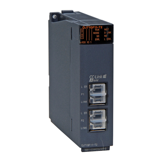
CHAPTER 2 PART NAMES CHAPTER 2 PART NAMES This chapter describes the names of each part of the master/local modules. Name Application RUN LED Indicates the operating status. Operating normally. A hardware failure or a watchdog timer error has occurred. MST LED Indicates the station type. - Page 34 Name Application Indicates the error status of the master/local module. The description of the errors can be confirmed in CC- ERR. LED Link IE Field Network diagnostics. ( Page 206, CHAPTER 9) One of the following errors has occurred: • A stop error occurs in the CPU module. •...
- Page 35 CHAPTER 2 PART NAMES Name Application PORT1 connector for CC-Link IE Field Network (RJ45 connector) Connect an Ethernet cable. ( Page 68, Section 6.3) There are no restrictions on the connection order of the cables for the "P1" connector and "P2" connector. •...
-
Page 36: Chapter 3 Specifications
CHAPTER 3 SPECIFICATIONS This chapter describes the specifications, function list, I/O signal, and buffer memory of the master/local module. General Specifications For the general specifications of the master/local module, refer to the following. QCPU User's Manual (Hardware Design and Maintenance and Inspection) Performance Specifications Item Specifications... - Page 37 CHAPTER 3 SPECIFICATIONS Item Specifications Communication speed 1Gbps Line topology, star topology (Coexistence of line topology and star topology is Network topology possible.), and ring topology An Ethernet cable that meets the 1000BASE-T standard: Category 5e or higher Connection cable (double shielded, STP), straight cable ( Page 59, Section 5.3.1) 100m max.
-
Page 38: Function List
Function List (1) Cyclic transmission :Available, ×: Not available Availability Master Function Description Reference station, Local submaster station station Communications The master station communicates I/O data in using RX and RY units of bits with other stations. Communications Page 88, Section 7.3 with other Page 124, Section Communications... - Page 39 CHAPTER 3 SPECIFICATIONS (2) Transient transmission :Available, ×: Not available Availability Master Function Description Reference station, Local submaster station station Transient transmission is performed to other Communications within the same Page 236, CHAPTER stations using dedicated instructions and GX network Works2.
- Page 40 Availability Master Function Description Reference station, Local submaster station station Only the station where an error occurs is disconnected, and data link continues with the stations that are operating normally. All stations after the faulty station are Loopback function Page 178, Section 8.7 disconnected in line topology.
- Page 41 CHAPTER 3 SPECIFICATIONS (5) Other functions :Available, ×: Not available Availability Master Function Description Reference station, Local submaster station station The reserved stations are included in the number of stations that will be connected to the network in the future without actually connecting Reserved station specification ×...
-
Page 42: List Of I/O Signals
List of I/O Signals This section lists I/O signals for the CPU module. The I/O signal assignment of when the start I/O number of the master/local module is "0000" (the module is mounted to the 0 slot of the main base unit) is listed below. The device X is an input signal from the master/local module to the CPU module. -
Page 43: List Of Buffer Memory Addresses
CHAPTER 3 SPECIFICATIONS List of Buffer Memory Addresses The buffer memory is used to exchange data between the master/local module and the CPU module. Buffer memory values are defaulted when the CPU module is reset or the system is powered off. Address Initial (Decimal... - Page 44 Address Initial (Decimal Name Read, write Refer to value (Hexadecimal)) 19712 Station No.1 RY offset (4D00 19713 Station No.1 RY size (4D01 19950 Station No.120 RY offset Page 468, (4DEE RY offset/size information Read Appendix 2.3 19951 Station No.120 RY size (4DEF 19952 Station No.0 RY offset...
- Page 45 CHAPTER 3 SPECIFICATIONS Address Initial (Decimal Name Read, write Refer to value (Hexadecimal)) 20512 Manufacturer code (5020 20513 Model type (5021 Own station (network card) Page 470, Read information Appendix 2.6 20514 Model code (5022 20515 Version (5023 20516 to 20519 ...
- Page 46 Address Initial (Decimal Name Read, write Refer to value (Hexadecimal)) 20552 Controller information valid/ (5048 invalid flag 20553 Manufacturer code (5049 20554 Model type (504A 20555 Page 471, Model code Read (504B Appendix 2.7 Other station (controller) information (station No.1) 20556 Version (504C...
- Page 47 CHAPTER 3 SPECIFICATIONS Address Initial (Decimal Name Read, write Refer to value (Hexadecimal)) 30224 Station No.1 (7610 PORT2 line error occurrence 30343 Read rate (max.) Station No.120 Page 472, (7687 Appendix 2.8 30344 Station No.0 (7688 30345 to 30351 System area (7689 to 768F 30352...
-
Page 48: Chapter 4 Procedures Before Operation
CHAPTER 4 PROCEDURES BEFORE OPERATION This chapter lists the procedures to be performed before operation of CC-Link IE Field Network. Remark • The programming chapter in this manual provides examples for each procedure (from “System consideration” to “Debugging”) described below. ( Page 387, CHAPTER 11) •... - Page 49 CHAPTER 4 PROCEDURES BEFORE OPERATION Check box Configuration Page 81, CHAPTER 7 Set the parameters for each module. Network diagnostics Perform a loop test on the master station, and check if it can properly Page 71, Section 6.4.1 communicate by the configured parameters. Programming Page 387, CHAPTER 11 Create a program.
-
Page 50: Chapter 5 System Configuration
CHAPTER 5 SYSTEM CONFIGURATION Overall System Configuration This section describes a system configuration example of when using a master/local module. Power supply module Master/local module CPU module... -
Page 51: Cc-Link Ie Field Network Configuration
CHAPTER 5 SYSTEM CONFIGURATION CC-Link IE Field Network Configuration This section describes CC-Link IE Field Network configurations. 5.2.1 Single network system (1) Overall system configuration A single network system is a system in which a master station and slave stations are connected using Ethernet cables as shown below. - Page 52 (2) Network configuration (a) Network topology The network can be wired into star topology, line topology, and ring topology. A network can consist of a combination of star and line topologies, but the ring topology cannot be combined with star or line topology. Switching hub Star topology Line topology...
- Page 53 CHAPTER 5 SYSTEM CONFIGURATION Item Description The network is configured into a star using a switching hub and Ethernet cables. Slave stations can be easily added to the network using this topology. Star topology Data link continues with the stations that are operating normally. The network is configured into a line by connecting the modules with Ethernet cables, but without a switching hub.
- Page 54 (c) Cascade connection Up to 20-level connection is available for the cascade connection. Switching hub Up to 20-level cascade connection Remark For wiring method, refer to Page 68, Section 6.3.
-
Page 55: Multi-Network System
CHAPTER 5 SYSTEM CONFIGURATION 5.2.2 Multi-network system The multi-network system is a system in which multiple networks are connected by some relay stations. Up to 239 networks can be connected. CC-Link IE Controller Network Network No.3 (Relay station) (Relay station) Network No.1 Network No.2 CC-Link IE... -
Page 56: Precautions
5.2.3 Precautions This section describes the precautions regarding the CC-Link IE Field Network configurations. (1) Adding slave stations (including the submaster stations) If a slave station (including a submaster station) is added to a system having 120 slave stations (including a submaster station), the system operates as follows. - Page 57 CHAPTER 5 SYSTEM CONFIGURATION • Connecting both PORT1 and PORT2 to the switching hub Switching hub Cannot connect both Ethernet ports to the switching hub. • Ring topology through a switching hub Switching hub...
- Page 58 (4) Ring topology To configure a ring topology, perform the following: • Check the serial number of the master/local module on the master station and the GX Works2 version. Page 546, Appendix 8) • Select "Use" under "Loopback Function Setting" in the network parameter window for the master station. Page 88, Section 7.3) (5) Using a switching hub to configure a ring topology If ring topology is configured by connecting two stations through two of the switching hub's ports, the following...
- Page 59 CHAPTER 5 SYSTEM CONFIGURATION A station during the RESET status and a station with no station number setting operate as an offline mode station does. (7) Connecting/disconnecting a cable and powering off/on a device When the operations listed below are performed, the system operates as described in (a) or (b). Network configuration Operation •...
- Page 60 Momentary data link error in all the stations Connecting/disconnecting a cable or power OFF/ON (8) Output hold when a data link error occurs To hold the outputs when a data link error occurs, configure the following settings: • Master/local module Set input data to be used from the faulty station.
-
Page 61: Network Components
● Cables for CC-Link IE Controller Network cannot be used for CC-Link IE Field Network. (1) Product Cables for CC-Link IE Field Network are available from Mitsubishi Electric System & Service Co., Ltd. (Catalogs for cable are also available.) Also, the connector processing of cable length is available for your preference. Please consult your local Mitsubishi Electric System &... -
Page 62: Hubs
5.3.2 Hubs Use hubs that meet all the conditions listed below: • Compliance with the IEEE802.3 (1000BASE-T) • Support of the auto MDI/MDI-X function • Support of the auto-negotiation function • Switching hub (layer 2 switch) Operation is not guaranteed if the hubs do not meet these conditions. A repeater hub is not available. -
Page 63: Applicable Systems
CHAPTER 5 SYSTEM CONFIGURATION Applicable Systems This section describes MELSEC-Q series systems that include the master/local module. Master/local module Software package available for Applicable CPU modules, number master/local modules of mountable modules Page 62, Section 5.4 (3) Page 61, Section 5.4 (1), Page 62, Section 5.4 (2) (1) Applicable CPU modules and the number of mountable modules (a) CPU module The following CPU modules are applicable to the master/local module. - Page 64 (2) Support for the multiple CPU system For using the master/local module in the multiple CPU system, refer to the following manual first. QCPU User's Manual (Multiple CPU System) (a) Applicable master/local modules The function version of the master/local has been "B" from the first release and supports the multiple CPU system.
-
Page 65: Chapter 6 Installation And Wiring
CHAPTER 6 INSTALLATION AND WIRING CHAPTER 6 INSTALLATION AND WIRING This chapter describes the installation and wiring of a master/local module. Installation This section describes the installation of a master/local module. (1) Setting method For details on the implementation of the master/local module, refer to the following. QCPU User's Manual (Hardware Design, Maintenance and Inspection) (2) Handling precautions The following is a list of precautions for handling the master/local module:... -
Page 66: Tests Before Wiring
Tests Before Wiring This section describes module tests that should be performed before network wiring. 6.2.1 Hardware test Hardware test checks the hardware inside the master/local modules. (1) Procedure Mount the master/local module on the base unit and connect GX Works2 to the CPU module. An Ethernet cable is not connected to the master/local modules. - Page 67 CHAPTER 6 INSTALLATION AND WIRING D LINK LED turns on when the test is completed. When completed • When completed The ×1 LED turns off. • When failed MODE D LINK Any one of the ×1 LEDs turns on, and the ERR. LED turns : On When the test fails, the possible cause is hardware failure ERR.
-
Page 68: Self-Loopback Test
6.2.2 Self-loopback test Self-loopback test checks the communication circuit of the master/local module. When conducting the self-loopback test, use a normal Ethernet cable. ( Page 59, Section 5.3) Mount the master/local module on the base unit, and connect GX Works2 to the CPU module. Set network parameters as shown in the figure to left. - Page 69 CHAPTER 6 INSTALLATION AND WIRING Self-loopback test begins. The MODE LED of master/local modules flashes, and : On each of the ×10 LED repeatedly turns on and off (1 2 : Flashing 4 8 1 • • •). L ER Also, the SD LED, RD LED, and LINK LED turn on.
-
Page 70: Wiring
Wiring This section describes the cable wiring and precautions. For network configuration, cables, and hubs used for the wiring, refer to the system configuration. ( Page 48, CHAPTER 5) (1) Ethernet cable connection (a) Connecting the cable Power off the master/local module and the connected device. - Page 71 Either one can be used. L ER LINK QJ71GF11-T2 • When using two connectors for line topology and ring topology, an Ethernet cable can be connected to the connectors in any combination. For example, the cable can be connected between PORT1s or between PORT1 and PORT2.
- Page 72 (2) Precautions This section describes wiring precautions. (a) Handling • Place the Ethernet cable in a duct or clamp them. If not, dangling cable may swing or inadvertently be pulled, resulting in damage to the module or cables or malfunction due to poor contact. •...
-
Page 73: Tests After Wiring
CHAPTER 6 INSTALLATION AND WIRING Tests After Wiring This section describes loop and cable tests that should be performed after network wiring. Perform these tests to the actual operating network configuration. 6.4.1 Loop test The loop test checks each station's network line and parameter setting status to verify whether the network is operating correctly. - Page 74 (a) Preparing for a loop test After wiring, set slave stations and a submaster station to the online mode before executing the loop test. Connect GX Works2 to the CPU module. Set slave stations and the submaster station to the online mode.
- Page 75 CHAPTER 6 INSTALLATION AND WIRING (b) Procedure Perform a loop test from the master station. Connect GX Works2 to the CPU module. Master station Set network parameters as shown in the figure to Select left. "CC IE Field (Master Station)". Project window [Parameter] [Network Parameter]...
- Page 76 Check the test result with LEDs of the master station. D LINK LED turns on when the test is completed. When completed • When completed The ×10 and ×1 LEDs turn off. • When failed MODE D LINK Any one of the ×10 and ×1 LEDs turns on, and the ERR. LED turns on.
- Page 77 CHAPTER 6 INSTALLATION AND WIRING Remark The test status and result can be viewed through monitoring the link special relays (SBs) on GX Works2. Item Description • Loop test completion status (SB0094): ON When completed • Loop test normal/abnormal end (SB0095): OFF •...
- Page 78 (2) Actions if the loop test fails (a) Checking by GX Works2 In the CC-Link IE Field Network diagnostics, identify the error location and take action. Then, execute the loop test again. Open the "CC IE Field Diagnostics" window. [Diagnostics] [CC IE Field Diagnostics] The error location is displayed in "Network Status".
- Page 79 CHAPTER 6 INSTALLATION AND WIRING In the following cases, the status of the corresponding station cannot be checked using the CC-Link IE Field Network diagnostics. • The network number of the station differs from those of other stations. • More than one master station exists in the network. •...
-
Page 80: Cable Test
6.4.2 Cable test Cable test checks if the Ethernet cables are properly connected. Only the Ethernet cable connected to the PORT1 or PORT2 of the target station is tested. For the whole network status, perform the loop test. ( Page 71, Section 6.4.1) Connect GX Works2 to the CPU module. -
Page 81: Communication Test
CHAPTER 6 INSTALLATION AND WIRING 6.4.3 Communication test Communication test checks if transient transmission data can be properly routed from the own station to the communication target. Take the following system configuration as an example of communication test procedure. CC-Link IE CC-Link IE Field Network Field Network... - Page 82 Write the network parameters set to the CPU module. [Online] [Write to PLC] Reset the CPU module or power off and on the system. RESET power OFF Open the "Communication Test" window and enter values for "Target Station" and "Communication Data Setting".
-
Page 83: Chapter 7 Parameter Setting
CHAPTER 7 PARAMETER SETTING CHAPTER 7 PARAMETER SETTING This chapter describes CC-Link IE Field Network parameters. The CC-Link IE Field Network parameters are set for either the master station or slave stations. This manual describes network parameters for master/local modules. For slave station settings, refer to the manuals for the slave stations used. -
Page 84: Parameter List
Parameter List The following table lists CC-Link IE Field Network parameters. (1) Parameters set for a master/local module : When required, : Cannot be set : Always, Necessity of setting Item Reference Master Local Submaster station station station Network Type Start I/O No. - Page 85 CHAPTER 7 PARAMETER SETTING Necessity of setting Item Reference Master Local Submaster station station station Parameter Name Network Data Link Faulty Station Setting Page 101, Operation Output Setting During CPU STOP Section 7.4 Settings Set IP address Page 103, Refresh Parameters Section 7.5 Page 107,...
-
Page 86: Network Settings
Network Settings Set the network number, station number, and other parameters for the master/local module. (1) Setting procedure Open the setting window. Project window [Parameter] [Network Parameter] [Ethernet/CC IE/MELSECNET] Set parameters in the window. Click the button. Item Description Setting range •... - Page 87 CHAPTER 7 PARAMETER SETTING Item Description Setting range Enter the network number of the master/local module. When mounting modules with the same network number on the same Network No. base unit, observe the following. 1 to 239 (Default: Blank) • One master station and one submaster station can be set. •...
- Page 88 Item Description Setting range • For the master station and submaster station Set a master station mode or a submaster station mode. Two online modes are available. Select an online mode according to the system. Mode Description This mode performs cyclic transmission and transient transmission without losing their inherent speed performance.
- Page 89 CHAPTER 7 PARAMETER SETTING Item Description Setting range Set the operating status of a network if a data link error occurs or the CPU module is set to STOP. In addition, the IP address of a master/local module is set to Page 101, Section 7.4 communicate data with Ethernet devices over CC-Link IE Field Network.
-
Page 90: Network Configuration Settings
Network Configuration Settings Set parameters of slave stations (the number of points and assignment of link devices) in the master station and submaster station. Set a link scan mode and block data assurance per station as well. Two methods are available to configure the network configuration settings as listed in the following table. Item Description The network configuration can be set while checking the CC-Link IE Field... - Page 91 CHAPTER 7 PARAMETER SETTING (1) How to configure the settings on the graphical window (CC IE Field configuration window) Select the checkbox next to "Set the network configuration setting in the CC IE Field configuration window". ( Page 84, Section 7.2) Configure the network setting.
- Page 92 (a) Setting the configuration of the slave station in the master station Item Description Setting range • Online (Normal Mode) • Online (High Speed Mode) • Offline Mode Setting • H/W Test Set the mode of the master station. ( Page 84, Section 7.2 (1)) •...
- Page 93 CHAPTER 7 PARAMETER SETTING Item Description Setting range • Points: Setting Station Type range Assign RWw/RWr points in increments of 4. ( Page 124, Section 8.1.1) Master Station, Local When "Sub-Master Station" is selected in "Station Type", points can also be Station, Intelligent 4 to 1024 Device Station, Sub-...
- Page 94 Item Description Setting range • Line/Star Change the transmission path method. The loopback function can Change Transmission Path • Ring Method be used by selecting "Ring". ( Page 178, Section 8.7) (Default: Line/Star)
- Page 95 CHAPTER 7 PARAMETER SETTING (c) Supplementary Setting [CC IE Field Configuration] [Supplementary Setting] Item Description Setting range Set "Link Scan Mode Setting", "Loopback Function Setting", "Block Data Assurance per Station", and "Operation Setting for Returning". Link Scan Mode Setting Item Description Link scan is performed asynchronously with the sequence scan of the CPU module.
- Page 96 Item Description Setting range Loopback Function Setting • Loopback Function Setting: Select whether to use the loopback function. ( Page 178, Selected (Use)/not selected Section 8.7) To configure a network in ring topology, select the (Default: Not selected) checkbox. When "Ring" is selected in [Change Transmission Path Method] •...
- Page 97 CHAPTER 7 PARAMETER SETTING (d) Equal assignment and identical point assignment of link points [CC IE Field Configuration] [Equal Assignment] or [Identical Point Assignment] Item Description Setting range Equally assign link devices to stations with preset conditions. • Start Station: 0 to the end station number •...
- Page 98 (f) Command execution of a slave station Select the module in the station list area. [CC IE Field Configuration] [Command Execution of Slave Station] The command of a slave station is executed. This can be performed when the slave station supports the command execution.
- Page 99 CHAPTER 7 PARAMETER SETTING (2) How to configure the settings on the window in the table format Set network setting parameters. ( Page 84, Section 7.2) Open the setting window. Project window [Parameter] [Network Parameter] [Ethernet/CC IE/MELSECNET] button Set parameters in the window. Click the button.
- Page 100 Item Description Setting range • Points: Setting Station Type range Assign RX/RY points. ( Page 124, Section 8.1.1) Points can be assigned in increments of 16 (Start: 0 , End: Master Station, Local Station, Intelligent F 16 to 2048 RX/RY Setting Device Station, Sub- Master Station When "Sub-Master Station"...
- Page 101 CHAPTER 7 PARAMETER SETTING Item Description Setting range Set "Link Scan Mode Setting", "Loopback Function Setting", "Block Data Assurance per Station", and "Operation Setting for Returning". Link Scan Mode Setting Item Description Link scan is performed asynchronously with the sequence scan of the CPU module. Select this item to Asynchronous shorten input transmission delay time when sequence scan takes much time than link scan.
- Page 102 Item Description Setting range Equally assign link devices to stations with preset conditions. • Start Station: 0 to the end station number • End Station: Number set to "Start Station" to the end station number • Start No.: Same values set in "RX/RY button Setting"...
-
Page 103: Network Operation Settings
CHAPTER 7 PARAMETER SETTING Network Operation Settings Set operating status of a network if a data link error occurs or the CPU module is set to STOP. In addition, the IP address of a master/local module is set to communicate data with Ethernet devices over CC-Link IE Field Network. - Page 104 Item Description Setting range Set the IP address of the master station and submaster station to communicate with Ethernet devices over CC-Link IE Field Network. Page 148, Section 8.3.2) Only the network address part (first and second octets) of the IP address needs to be set.
-
Page 105: Refresh Parameters
CHAPTER 7 PARAMETER SETTING Refresh Parameters Set link refresh ranges between the link devices of the master/local module and the devices of the CPU module. (1) Setting procedure Set network setting parameters. ( Page 84, Section 7.2) Open the setting window. Project window [Parameter] [Network Parameter]... - Page 106 Item Description Setting range Set the link refresh ranges of RX, RY, RWr, and RWw. Up to 256 • Link Side: RX, RY, RWr, RWw ranges can be set. ( Page 127, Section 8.1.2) • PLC Side: When RX is set to "Link Side": X, M, L, B, D, W, R, ZR When RY is set to "Link Side": Dev.
- Page 107 CHAPTER 7 PARAMETER SETTING (2) Checking method Click the button in the "Network Parameter - MELSECNET/CC IE/Ethernet Module Configuration" window to open the "Assignment Image" window. ( Page 84, Section 7.2) Select the devices to be checked and the magnification ratio in the window. 1) Click 2) Set "Device (PLC side)",...
- Page 108 (3) Precautions (a) Device set to "Device (PLC Side)" Set a device range not to overlap the one used for the following: • Refresh parameters for other network modules • Auto refresh parameters for CC-Link master/local module • I/O numbers used for I/O modules and intelligent function modules •...
-
Page 109: Interrupt Settings
CHAPTER 7 PARAMETER SETTING Interrupt Settings Set conditions for sending an interrupt request to the CPU module. (1) Setting procedure Set network setting parameters. ( Page 84, Section 7.2) Open the setting window. Project window [Parameter] [Network Parameter] [Ethernet/CC IE/MELSECNET] button Set parameters in the window. - Page 110 (Setting range) Device Device Interrupt Word Device Channel No./ Interrupt Detection Method Code Condition Setting Value Connection No. (SI) No. to 3FFF Level Detect and ON: Interrupt occurs by turning on the device. to 3FFF Level Detect and OFF: Interrupt occurs by turning off the device.
- Page 111 CHAPTER 7 PARAMETER SETTING Using an interrupt program will eliminate the need for describing a start condition in a program. This leads to reduction in the number of steps and sequence scan time. (2) Precautions (a) When "Level Detect" is set for "Detection Method" and the interrupt condition is always met If the sequence scan takes much longer than the link scan, since interrupt processing is activated in each link scan, sequence scan time may greatly increase, resulting in a watchdog timer error of the CPU module.
- Page 112 (e) Starting an interrupt program by the rising/falling edge of the specified device Do not start an interrupt program using instructions, such as PLS and PLF, that depend on the rising/falling edge of the specified devices because changes in devices might not be read. Sending an interrupt request by turning on RX100 in a station in network number 7 Since change of RX100 may not be read, X100...
- Page 113 CHAPTER 7 PARAMETER SETTING (3) Setting example (a) Starting the interrupt program of the master station (station number 0) when RX100 turns on The following is a setting example to execute the interrupt program corresponding to the interrupt pointer I50 when RX100 turns on by turning on the corresponding switch on the slave station side.
- Page 114 (b) Starting the interrupt program of the master station (station number 0) when the master station receives data sent from another station using the SEND instruction The following is a setting example to execute the interrupt program corresponding to the interrupt pointer I52 when the master station (station number 0) receives data sent from the local station (station number 1) using the SEND instruction in channel 2.
-
Page 115: Interlink Transmission Parameters
CHAPTER 7 PARAMETER SETTING Interlink Transmission Parameters Set link device ranges when cyclic data are transferred from a station in the own network to a station in another network. (1) Setting procedure Set network setting parameters. ( Page 84, Section 7.2) Open the setting window. - Page 116 Item Description Setting range Enter the link device range of the transfer source and destination modules. Up to 64 ranges can be set. RX and RY points can be assigned in increments of 16 (Start: 0 , End: F Transfer When the transfer source is When the transfer target is From...
- Page 117 CHAPTER 7 PARAMETER SETTING Click the button in the "Network Parameter - MELSECNET/CC IE/Ethernet Module Configuration" window to open the "Assignment Image" window. Select the devices to be checked and magnification ratio in the window. Select the devices and magnification ratio in "Device (PLC Side)", "Device (Link Side)", and "Display Magnification".
- Page 118 (2) Precautions (a) Stations supporting interlink transmission Interlink transmission parameters can be set for the master station and submaster station. (b) Modules supporting interlink transmission The master station and submaster station can perform interlink transmission with the following modules. • CC-Link IE Controller Network module (control station, normal station) •...
- Page 119 CHAPTER 7 PARAMETER SETTING (e) Performing interlink transmission in a multiple CPU system When different control CPUs are set for the network modules, interlink transmission cannot be performed using interlink transmission parameters or a program. Use the CPU shared memory of the multiple CPU system. (3) Setting example The following is a setting example to perform interlink transmission from the master station on CC-Link IE Field Network to stations on CC-Link IE Controller Network.
- Page 120 If the transfer target network module is on a network other than CC-Link IE Field Network, set the transfer target link devices within the own station's send range of the network module. If the link devices are set within another station's send range, the transferred data are overwritten with another station's send data.
-
Page 121: Routing Parameters
CHAPTER 7 PARAMETER SETTING Routing Parameters Set communication paths for transient transmission between a station in the own network and stations in other networks. The parameters need to be set in the following cases. • To perform transient transmission with stations on different networks using dedicated instructions Page 236, CHAPTER 10) •... - Page 122 Item Description Setting range Set a relay station of the own network to send data to a station on another network by transient transmission. Up to 64 communication paths can be set. Set routing parameters as shown below. Target Network No. 1 to 239 (Default: Blank) Setting to transmit data to network number ●...
- Page 123 CHAPTER 7 PARAMETER SETTING (2) Checking method To check whether routing parameters have been correctly set and transient transmission can be performed, perform a communication test from CC-Link IE Field Network diagnostics. ( Page 79, Section 6.4.3) (3) Precautions (a) Different control CPUs are set to the network modules on a relay station in a multiple CPU system Set the same routing parameters to all the control CPUs.
- Page 124 (4) Setting example The following is a setting example to perform transient transmission from the station number 2 of the network number 1 to the station number 4 of the network number 3. CC-Link IE Field Network Network No.1 Master station (Request source) Station Station...
-
Page 125: Chapter 8 Functions
CHAPTER 8 FUNCTIONS CHAPTER 8 FUNCTIONS This chapter describes the functions of the master/local module. Cyclic Transmission Data communication is available periodically among stations on the same network. Link devices (RX, RY, RWr, and RWw) are used. -
Page 126: Data Flow And Link Device Assignment
8.1.1 Data flow and link device assignment (1) Master and slave stations (except for local stations) One-to-one communication is possible between the master and slave stations. The status information of the link devices (RY and RWw) of the master station is output to the external device of the slave station, and the input status information from the external device of the slave station is stored in the link devices (RX and RWr) of the master station. - Page 127 CHAPTER 8 FUNCTIONS (2) Master and local stations Data can be written into the send range of each station's link device (RY, RWw) and can be sent to any station on the same network. The status data of the link devices (RY, RWw) of the master station are stored in the link devices (RX, RWr) of each local station.
- Page 128 (3) Coexistence of local stations and the other slave stations (other than local stations) The data of all slave stations are also stored in the local stations in the same way as the master station. Station No.0 Station No.1 Station No.2 Station No.3 Master Slave station...
-
Page 129: Link Refresh
CHAPTER 8 FUNCTIONS 8.1.2 Link refresh Data can be automatically transferred between the link devices of the master/local module and the devices of the CPU module. Master/local module module Link Device device Link refresh (1) Concept of the link refresh range The link refresh is performed to the area set with the refresh parameters and also set in the network configuration settings. - Page 130 (3) Setting method The link refresh is assigned by the Refresh Parameters. ( Page 103, Section 7.5) (4) Precautions For cyclic data assurance of more than 32 bits, use one of the following methods. • Enable the Block Data Assurance per Station setting. ( Page 88, Section 7.3, Page 134, Section 8.1.5) •...
-
Page 131: Direct Access To Link Devices
CHAPTER 8 FUNCTIONS 8.1.3 Direct access to link devices Direct access to each link device (RX, RY, RWr, RWw, SB, or SW) of the master/local module is possible from the program. Specify a link device as the link direct device (J\) for direct access. (1) Specification method Specify the network No. - Page 132 (2) Readable and writable range Data can be read or written between the master/local module and CPU module mounted on the same base unit. (a) Read All link devices of the master/local module can be specified. ( Page 129, Section 8.1.3 (1)) (b) Write The range that satisfies all of the following conditions can be specified.
- Page 133 CHAPTER 8 FUNCTIONS When writing data to the area in the link refresh range, directly access the link device and write the same data in the device of the CPU module. Bad example (Only direct access to the link refresh target) CPU module Master/local module MOV K20 J1\W100...
- Page 134 (3) Differences from link refresh Access method Item Link refresh Direct access Number of steps 1 step 2 steps High speed (0.0095µs) Low speed (10 to 100µs) Processing speed (LD B0 *2*3 Data reliability Station-based or 32-bit units The given value is for the Q06UDEHCPU. When “Block Data Assurance per Station”...
-
Page 135: Interlink Transmission (For The Master Station And Submaster Station Only)
CHAPTER 8 FUNCTIONS 8.1.4 Interlink transmission (for the master station and submaster station only) A relay station transfers the link devices of the master station and submaster station to another network module. Relay station Master/local Network module module Interlink transmissions Data of network No.2 Data of network No.1 Network No.1... -
Page 136: Assurance Of Cyclic Data Integrity
8.1.5 Assurance of cyclic data integrity The cyclic data integrity can be assured in 32-bit units or for each station. : Assured ×: Not assured Assurance Access to Method Description Direct access Link refresh buffer to link devices memories Assures data in 32-bit units. Data is automatically assured 32-bit data assurance by satisfying assignment... - Page 137 CHAPTER 8 FUNCTIONS (a) Access to cyclic data When link devices are accessed, the integrity of 32-bit data can be assured by satisfying the following conditions. • When directly accessing link devices: The start device number of RWr/RWw is multiples of 2. The number of points assigned to RWr/RWw is multiples of 2.
- Page 138 (2) Block data assurance per station Integrity of the cyclic data is assured for each station by handshake between the CPU module and master/local module for a link refresh. (a) Setting Enable "Block Data Assurance per Station" in "Network Configuration Settings" of the master station. Page 88, Section 7.3) Once this setting is enabled on the master station, integrity of the data for all stations is assured for each station.
- Page 139 CHAPTER 8 FUNCTIONS (3) Interlock program Data of more than 32 bits can be assured with the Block Data Assurance per Station setting disabled. Use either of the following methods. • Interlock using X and Y • Interlock using devices other than X and Y (when X, Y cannot be used as an interlock device) (a) Example of interlock using X and Y An example of sending data in W0 to W3 of the master station (station No.0) to W1000 to W1003 of the local station (station No.1) is shown below.
- Page 140 (b) Example of interlock using devices other than X and Y The following shows an example of sending data in W0 to W3 of the master station (station No.0) to W1000 to W1003 of the local station (station No.1). This is a method used when X and Y cannot be used as interlock devices.
-
Page 141: Scan Synchronization Specification
CHAPTER 8 FUNCTIONS 8.1.6 Scan synchronization specification Whether to synchronize the link scan with the CPU module's sequence scan or not can be selected. (1) Difference between asynchronous and synchronous settings (a) Asynchronous setting Link scan is performed asynchronously with the sequence scan of the CPU module. Select this item to shorten input transmission delay time when sequence scan takes much time than link scan. -
Page 142: Input And Output Status Settings In Case Of Failure
8.1.7 Input and output status settings in case of failure For the master/local module, status of input from a data link faulty station and output status of cyclic data if a stop error occurs in the CPU module can be set. Status Range where the settings are enabled Whether to clear or hold the following RX and RY input data can be selected. - Page 143 CHAPTER 8 FUNCTIONS (1) Setting method (a) Input status of data link faulty station Set this item in the "Network Operation Settings" window. ( Page 101, Section 7.4) (b) Cyclic data output when a stop error occurs in the CPU module Select "PLC Parameter"...
-
Page 144: Output Status Setting For Cpu Module Stop
8.1.8 Output status setting for CPU module STOP When the CPU module mounted with a master/local module is set to STOP, whether cyclic data output is held or cleared can be selected. (1) Range where the setting becomes enabled The setting is fixed to hold or clear depending on devices set to link refresh, regardless of the output setting during CPU STOP. -
Page 145: Cyclic Transmission Stop And Restart
CHAPTER 8 FUNCTIONS 8.1.9 Cyclic transmission stop and restart During debugging and other operations, cyclic transmission is stopped. (Data reception from a slave station and data sending from the own station are stopped.) Also, the stopped cyclic transmission can be restarted. Transient transmission does not stop. -
Page 146: Transient Transmission
Transient Transmission This function allows communication with other stations when a request is made by a method such as a dedicated instruction. Communication is also possible with different networks. 8.2.1 Communications within the same network Transient transmission can be performed to other stations through dedicated instructions or GX Works2. ( Page 236, CHAPTER 10) With a dedicated instruction (READ), accessing a programmable controller of another station... -
Page 147: Communications With Different Networks
CHAPTER 8 FUNCTIONS 8.2.2 Communications with different networks By presetting the routing parameters (communication route) using GX Works2, transient transmission can be performed to stations on different networks through GX Works2. Seamless communications are available with the following networks. ( Page 119, Section 7.8) •... -
Page 148: Ip Packet Transfer Function
IP Packet Transfer Function Communications using the specified IP address can be performed over CC-Link IE Field Network. For example, a personal computer can communicate with the FTP server. With this function, two networks of CC-Link IE Field Network and Ethernet are not required, resulting in reduced wiring cost. -
Page 149: System Configuration Of The Ip Packet Transfer Function
CHAPTER 8 FUNCTIONS 8.3.1 System configuration of the IP packet transfer function The IP packet transfer function allows communications to be performed by connecting an Ethernet device to one of the following devices. (1) Connecting an Ethernet device to a CPU module Connect an Ethernet device to an Ethernet port on a Built-in Ethernet port QCPU. -
Page 150: How To Set The Ip Packet Transfer Function
8.3.2 How to set the IP packet transfer function To use the IP packet transfer function, the following items need to be set. Ethernet device Ethernet device (request source device) (request destination device) : Communication route Ethernet device gateway address setting IP address of the CPU module ( Page 152, Section 8.3.2 (2) (a)) IP packet transfer setting (... - Page 151 CHAPTER 8 FUNCTIONS (1) Rules for the IP address setting The IP address of when using the IP packet transfer function need to satisfy the following rules. Setting range of the IP address Device to be set First and second octets Third octet Fourth octet Ethernet device...
- Page 152 Use the same number for the third octet (network number) of the IP addresses of an Ethernet device and a CPU module connected to the Ethernet device. Ethernet device IP address setting (request source device) not required 192.168.2.125 192.168.7.18 Built-in Master Universal Local...
- Page 153 CHAPTER 8 FUNCTIONS ● CC-Link IE Field Network gateway setting Through a module, such as an Ethernet adapter module, where the CC-Link IE Field Network gateway setting can be configured, any IP address can be used for the Ethernet device side. ( Page 158, Section 8.3.4, Page 166, Section 8.3.7 (2) Note, however, that the network addresses on the CC-Link IE Field Network side must be the same.
- Page 154 (2) Setting procedure For a communication example, refer to Page 162, Section 8.3.7 (a) Setting in the CPU module Open the "Q Parameter Setting" window to set the IP address. Project window [Parameter] [PLC Parameter] "Built-in Ethernet Port Setting" Follow the rules to set the address. ( Page 149, Section 8.3.2 (1)) Click the...
- Page 155 CHAPTER 8 FUNCTIONS Set the routing parameters. Project window [Parameter] [Network Parameter] [Ethernet/CC IE/MELSECNET] button For details on the routing parameters, refer to the following. Item Description Set the own network station where communications are transmitted through to reach the Ethernet device. Set the routing parameters for all the CPU modules on the communication route.
- Page 156 ● When an Ethernet device is connected to a module, such as an Ethernet adapter module, that does not support the routing parameters Set the routing parameters so that communications are transmitted through the master station. Communications from a module that does not have the routing parameters are automatically transmitted through the master station.
- Page 157 CHAPTER 8 FUNCTIONS (b) Setting in the master station Open the "Network Operation Settings" window. Project window [Parameter] [Network Parameter] [Ethernet/CC IE/MELSECNET] button In the "Set IP address" field, set the network address. Follow the rules to set the address. ( Page 149, Section 8.3.2 (1)) Remark...
-
Page 158: Ip Communication Test
8.3.3 IP communication test When the IP packet transfer function is used, whether no error occurs in the communication route within CC-Link IE Field Network is checked. The following can be checked using the IP communication test: • Cables are properly connected on the communication route. •... - Page 159 CHAPTER 8 FUNCTIONS Open the "IP Communication Test" window. Enter the IP address of the CPU module or the master/ local module connected to the request destination device in "Communication Target". When the module that is connected to the request destination device is an Ethernet adapter module, enter the IP address of the request destination device in "Communication Target".
-
Page 160: Accessible Range
8.3.4 Accessible range The accessible range differs depending on whether the conditions listed in Page 149, Section 8.3.2 (1) are met or not. • When one of the Ethernet devices does not have an IP address that does not meet the IP address setting rules, both of the request source device and request destination device need to be connected to a module, such as an Ethernet adapter module, supporting the CC-Link IE Field Network gateway setting. -
Page 161: Relay Using Cc-Link Ie Controller Network
CHAPTER 8 FUNCTIONS 8.3.5 Relay using CC-Link IE Controller Network The IP packet transfer function can be used through a relay from CC-Link IE Field Network to CC-Link IE Controller Network. Request destination 3 Request destination 2 Ethernet Ethernet CC-Link IE Controller Network Relay station CC-Link IE Field Network Ethernet... - Page 162 8.3.6 Precautions (1) Modules supporting the IP packet transfer function (a) Master/local module and GX Works2 Before using the IP packet transfer function, check the versions of the master/local module and GX Works2. Page 546, Appendix 8) (b) CPU module To use the IP packet transfer function, all the CPU modules on the communication route must support the function.
- Page 163 CHAPTER 8 FUNCTIONS (6) Precautions when configuring a multiple CPU system Set a CPU module connected to an Ethernet device as a control CPU of the master/local module performing the IP packet transfer. Any QnUCPU in a relay station on CC-Link IE Field Network can be served as a control CPU of the master/local module transferring the IP packet.
-
Page 164: Example Of Communications Using The Ip Packet Transfer Function
8.3.7 Example of communications using the IP packet transfer function (1) When the request source device and request destination device have the same network address The following system configuration is used to explain an example of communications. Ethernet device Ethernet device CPU module 1: 192.168.1.10 CPU module 2: 192.168.10.10 (request source device) - Page 165 CHAPTER 8 FUNCTIONS Configure the IP packet transfer setting in the CPU module 1. Project window [Parameter] [PLC Parameter] "Built-in Ethernet Port Setting" button Set the routing parameters in the CPU module 1. Project window [Parameter] [Network Parameter] [Ethernet/CC IE/MELSECNET] button Set the IP address in the master station (station number 0).
- Page 166 (b) Setting in the CPU module 2 and local station (station number 2) Set the IP address in the CPU module 2. Project window [Parameter] [PLC Parameter] "Built-in Ethernet Port Setting" Configure the IP packet transfer setting in the CPU module 2. Project window [Parameter] [PLC Parameter]...
- Page 167 CHAPTER 8 FUNCTIONS Set the routing parameters in the CPU module 2. Project window [Parameter] [Network Parameter] [Ethernet/CC IE/MELSECNET] button The local station (station number 2) does not require an IP address. The network address set in the master station (station number 0) is automatically assigned. Write the set parameters to the CPU module 2.
- Page 168 (2) When accessing an Ethernet device with a different network address The following system configuration is used to explain an example of communications. Ethernet device Ethernet device Ethernet adapter Master station 1 Ethernet adapter (request destination device) Local station 1 (station No.2) (request source device) module 2 (station No.0)
- Page 169 CHAPTER 8 FUNCTIONS Configure the CC-Link IE Field Network gateway setting in the Ethernet adapter module 1. Setting item tree NZ2GF-ETB [Parameter] "CC-Link IE Field Network" Configure the setting as follows. To transmit communications to the request destination the IP packet passes through the station with the network address No.
- Page 170 (b) Setting in the CPU module 1 and master station 1 (station number 0) Set the routing parameters to the CPU module 1. Because the network address is different from that of the request destination device, the Ethernet adapter module 2 (Ethernet part) does not have a network number. Set the communication route to the network number 2.
- Page 171 CHAPTER 8 FUNCTIONS (c) Setting in the CPU module 2, local station 1 (station number 2), and master station 2 (station number 0) Set the routing parameters to the CPU module 2. Project window [Parameter] [Network Parameter] [Ethernet/CC IE/ MELSECNET] button Set the IP address in the master station 2 (station number 0).
- Page 172 (d) Setting in the Ethernet adapter module 2 (station number 1) Set the IP address to the Ethernet adapter module 2 (Ethernet part). Use the configuration tool to set the IP address in the Ethernet adapter module 2 (Ethernet part). Setting item tree NZ2GF-ETB [Parameter]...
- Page 173 CHAPTER 8 FUNCTIONS (e) Checking the status of communications After the setting is completed in each module, execute the IP communication test using the configuration tool of the Ethernet adapter module. Then check for an error in the communication route between the Ethernet device (request source device) and Ethernet device (request destination device).
-
Page 174: Communication Speed
8.3.8 Communication speed This section provides the results of communication speed measured using the IP packet transfer function. Use the results as a reference. (1) When a request source device and a request destination device are connected to a CPU module The results are based on measurement when FTP communications are performed with four modules connected in star topology. - Page 175 CHAPTER 8 FUNCTIONS (b) Measurement result of the communication speed The following table lists the time that takes until a file is read from a request source device to a request destination device. Size of a file to be communicated Time 1K byte 10ms...
- Page 176 (3) To increase communication speed Communication speed can be increased by checking the following items again. Item Description Shortening sequence scan time can increase communication speed. For causes extending sequence scan time, refer to the following. Sequence scan of a CPU module QnUCPU User’s Manual (Function Explanation, Program Fundamentals) Communications using the IP packet transfer function are performed with transient transmission.
-
Page 177: Reserved Station Specification And Temporary Cancel Of Reserved Station Setting
CHAPTER 8 FUNCTIONS Reserved Station Specification and Temporary Cancel of Reserved Station Setting Reserved station specification allows setting of a station that is not actually connected at present but will be connected to the network in the future (must be included in the total number of stations on the network). Reserved stations are not detected as faulty stations even though they are not actually connected. -
Page 178: Error Invalid Station And Temporary Error Invalid Station Setting Function
Error Invalid Station and Temporary Error Invalid Station Setting Function When a slave station is set as an error invalid station, even if it is disconnected from the network during data link, the master station will not detect it as faulty station. Furthermore, by the temporary error invalid station setting function, a slave station can be temporarily set as an error invalid station without changing the GX Works2 setting each time. -
Page 179: Interrupt Request To The Cpu Module
CHAPTER 8 FUNCTIONS Interrupt Request to the CPU Module Interrupt conditions are checked every link scan, and if the interrupt conditions are met, an interrupt request is made to the CPU module to start the interrupt program. CPU module Master/local module Conditions Interrupt condition check... -
Page 180: Loopback Function
Loopback Function This function disconnects the station in which an error has occurred from the network and continues data link with the stations that are operating normally. Stations connected after the faulty station can also continue data link. To use this function, configure the network in ring topology and select "Use" under "Loopback Function Setting" in the Network Parameter window for the master station. - Page 181 CHAPTER 8 FUNCTIONS (1) Setting procedure Configure the network in ring topology. Select "Use" under "Loopback Function Setting" in the network configuration settings for the master station. Project window [Parameter] [Network Parameter] [Ethernet/CC IE/MELSECNET] button [CC IE Field Configuration] [Supplementary Setting] Select the checkbox.
-
Page 182: Submaster Function
Submaster Function Connecting the master station and submaster station on the same network allows the submaster station to continue controlling slave stations instead of the master station even if the master station is disconnected. Using this function prevents the entire network from going down due to disconnection of the master station. Master station Slave station Slave station... -
Page 183: Cyclic Transmission Of When The Submaster Function Is Used
CHAPTER 8 FUNCTIONS 8.8.1 Cyclic transmission of when the submaster function is used In cyclic transmission, data are periodically communicated among stations on the same network. Link devices (RX, RY, RWr, RWw) are used for data communications. In the submaster function, the submaster station is performing data link in case of disconnection of the master station;... - Page 184 (b) After the control is switched Because areas of sending data to the slave stations in the submaster station are assigned in the same way as the master station, the submaster station sends data to the slave stations as the master station does before the control is switched. Because areas of receiving data from the slave stations in the submaster station are assigned in the same way as the master station, the submaster station receives data from the slave stations as the master station does before the control is switched.
- Page 185 CHAPTER 8 FUNCTIONS (2) Link device assignment of the master station, submaster station, and slave stations The following are assignment examples of when salve stations are connected to the master station and submaster station. (a) When the master station and a local station are connected Submaster Master operation operation...
- Page 186 (b) When the master station and slave stations (excluding a local station) are connected Submaster Master operation operation Station No.0 Station No.1 Station No.2 Station No.3 Submaster Slave station Slave station Master station station RX, RWr RX, RWr Station Station RX, RWr No.0 No.0...
- Page 187 CHAPTER 8 FUNCTIONS (c) When a slave station (excluding a local station) and a local station are connected Submaster Master operation operation Station No.0 Station No.1 Station No.2 Station No.3 Submaster Local station Slave station Master station station RX, RWr RX, RWr RX, RWr RX, RWr...
-
Page 188: Transient Transmission Of When The Submaster Function Is Used
8.8.2 Transient transmission of when the submaster function is used In transient transmission, communications can be performed with other stations when requests are issued using dedicated instructions. Communications can be also performed with other networks. Transient transmission can be performed from either the master station or submaster station. (Note, however, that the REMFR and REMTO instructions can be executed only from the master operating station.) Access from a local station or submaster station to a programmable controller on another station using a dedicated instruction (READ) -
Page 189: Example Of Communications Using The Submaster Function
This section describes a procedure up to the system operation using the submaster function. (1) System configuration The following system configuration is used for explanation purpose. Power supply module (Q62P) CPU module (Q10UDHCPU) Master/local module (QJ71GF11-T2) Input module (QX10) Output module (QY10) X/Y00 X/Y00... - Page 190 (b) RWr/RWw assignment The setting for the link refresh target device of the local station is the same as that of the master station. CPU module Master station Local station Submaster station CPU module 1000 1000 Station Station Station Station Station No.0 No.0...
- Page 191 CHAPTER 8 FUNCTIONS (3) Setting (a) Setting in the master station Connect GX Works2 to the master station and set parameters. Set parameters. Master station (station No.0) Local station (station No.1) Submaster station (station No.2) Open the network parameter window and set parameters as follows. Project window [Parameter] [Network Parameter]...
- Page 192 Select "Hold Input Data (RX/RY)" under "Data Link Faulty Station Setting". Project window [Parameter] [Network Parameter] [Ethernet/CC IE/MELSECNET] button Open the refresh parameter window and set parameters as follows. Project window [Parameter] [Network Parameter] [Ethernet/CC IE/MELSECNET] button Write the set parameters to the CPU module on the master station. [Online] [Write to PLC] In this setting example, default settings are used for the parameters other than those described.
- Page 193 CHAPTER 8 FUNCTIONS (b) Setting in the local station Connect GX Works2 to the local station and set parameters. Set parameters. Master station (station No.0) Local station (station No.1) Submaster station (station No.2) Open the network parameter window and set parameters as follows. Project window [Parameter] [Network Parameter]...
- Page 194 (c) Setting in the submaster station Connect GX Works2 to the submaster station and set parameters. Set parameters. Master station (station No.0) Local station (station No.1) Submaster station (station No.2) Open the network parameter setting window and set parameters as follows. Project window [Parameter] [Network Parameter]...
- Page 195 CHAPTER 8 FUNCTIONS (4) Starting up the system Reset the CPU module or power off and on the system in order of the local station, master station, and submaster station. RESET or Power OFF Start up the master station before the submaster station. If the submaster station is started up first, it may operate as a master operating station.
- Page 196 (5) Checking the network status After starting up the system, check whether data link can be normally performed using the CC-Link IE Field Network diagnostics in GX Works2. Connect GX Works2 to the master station. In the menu, start up the CC-Link IE Field Network diagnostics. [Diagnostics] [CC IE Field Diagnostics] If the following display appears, data link is normal.
- Page 197 CHAPTER 8 FUNCTIONS (6) Program example Create the following programs in the project for the master station, local station, and submaster station using GX Works2. • Master station (station number 0) Receiving process from the station No.1 Sending/receiving processes with the station No.1 Sending process to the station No.1 (master operating station process) Create programs of the same structure as "Sending/receiving processes with...
- Page 198 • Submaster station (station number 2) Receiving process from the station No.1 Sending/receiving processes with the station No.1 Sending process to the station No.1 (master operating station process) Create programs of the same structure as "Sending/receiving processes with the station No.1" by the number of slave stations (exclusive of the master station).
-
Page 199: Programming For When The Submaster Function Is Used
CHAPTER 8 FUNCTIONS 8.8.4 Programming for when the submaster function is used This section describes the programming of when the submaster function is used. For other programming, refer to the following. • Cyclic transmission: Page 387, CHAPTER 11 • Transient transmission: Page 236, CHAPTER 10 (1) Programming for cyclic transmission After checking that data link is normally performed, create a program to control slave stations. - Page 200 (b) When the operation is switched between the master operation and submaster operation When the operation is switched between the master operation and submaster operation, a temporary data link error is detected (SB0049 and SB00B0 turn on). While the operation is being switched, do not use cyclic data and the following signals. Device Description Device...
-
Page 201: Switch From The Master Station To The Submaster Station
CHAPTER 8 FUNCTIONS 8.8.5 Switch from the master station to the submaster station This section describes conditions where the master operating station is switched to the submaster operating station. (1) Automatic switch The control is switched under one of the following conditions. Condition Description If an error occurs in the master station while the master station is operating as a master operating... - Page 202 (2) Manual switch While a submaster station is operating as a master operating station, the operation of the master station can be switched from the submaster operation to the master operation with the procedure described below. Note, however, that this does not apply when the master station is operating as a master operating station. Cyclic transmission is continued during switch.
- Page 203 CHAPTER 8 FUNCTIONS (a) Sample program of a manual switch • Devices used in the program Device Description Device Description SB0019 Forced master switch command SB00A1 Baton pass status (master station 1) Own station master/submaster function SB004E SB00B1 Data link status (master station 1) operation status Forced master switch command SB0066...
-
Page 204: Changes In The Parameters When The Submaster Station Is Used
8.8.6 Changes in the parameters when the submaster station is used This section describes how to change the parameters when the submaster function is used. (1) When the setting is configured in the network parameter window of GX Works2 When the setting is configured in the network parameter window of GX Works2, the CPU module needs to be reset. - Page 205 CHAPTER 8 FUNCTIONS 8.8.7 Precautions This section describes the precautions regarding the submaster function. (1) Versions of the master/local module and GX Works2 Before using the submaster function, check the versions of the master/local module and GX Works2. ( Page 546, Appendix 8) All the master/local modules on a network where the submaster function is used must support the submaster function.
- Page 206 (5) Use of a safety station When using the submaster function, do not use a safety station, such as the QS0J71GF11-T2, for a slave station. When the control is switched between a master station and a submaster station, an error may occur in safety communications.
- Page 207 CHAPTER 8 FUNCTIONS (10)Access to the specified master station and submaster station in transient transmission Access to the specified master station and submaster station cannot be performed using GX Works2 or dedicated instructions in the following modules: • A master/local module with a serial number (first five digits) of "14022" or earlier •...
-
Page 208: Chapter 9 Cc-Link Ie Field Network Diagnostics
CHAPTER 9 CC-LINK IE FIELD NETWORK DIAGNOSTICS This chapter describes how to check error locations, error causes, and event history using the CC-Link IE Field Network diagnostic function of GX Works2. With this function, the status of other stations can also be monitored. Diagnostic Items The following table lists items that can be diagnosed by the CC-Link IE Field Network diagnostics when GX Works2 is connected to the master/local module. - Page 209 CHAPTER 9 CC-LINK IE FIELD NETWORK DIAGNOSTICS : Diagnosed : Diagnosed with restrictions ×: Not diagnosed GX Works2 is connected to: Master Item Restrictions Reference station or Local submaster station station Display of network map and error status Display of disconnected cable and disconnected station This item is not displayed Page 214, Section 9.3...
-
Page 210: Starting Diagnostics
Starting Diagnostics This section describes how to use the CC-Link IE Field Network diagnostics. (1) Procedure Connect GX Works2 to the CPU module. If a slave station cannot be monitored due to an error such as cable disconnection, directly connect the supported programming tool to the slave station. - Page 211 CHAPTER 9 CC-LINK IE FIELD NETWORK DIAGNOSTICS When the following window opens, select the master/local module to be diagnosed and click the button to start the CC-Link IE Field Network diagnostics. Modules are listed in the order configured in network settings. ( Page 84, Section 7.2) When multiple master/local modules of the same network number are mounted on the same base unit, the module with the smallest start I/O number is always diagnosed, regardless of setting.
- Page 212 Select the station to be diagnosed from "Select Station" or "Network Status". • , or is displayed on the module icon of the station where an error occurs. • A disconnected station that has performed data link is indicated with the icon in the network map.
- Page 213 CHAPTER 9 CC-LINK IE FIELD NETWORK DIAGNOSTICS ● Descriptions of icons Click the button. A brief description of the icon is displayed. ● When multiple master/local modules are mounted on the same base unit Clicking the button will change the target module. Click.
- Page 214 Status of a station selected in "Network Status" is displayed in "Selected Station Communication Status Monitor". ( Page 214, Section 9.3) The station status is displayed on the top of "Selected Station Communication Status Monitor". If an error occurs, a button indicating the error (e.g. button) is displayed.
- Page 215 CHAPTER 9 CC-LINK IE FIELD NETWORK DIAGNOSTICS (2) Measures if is displayed in "Network Status" even though loopback is not performed (a) If the system does not contain a switching hub Ring topology is configured even though the loopback function is disabled. Take the following measures: •...
-
Page 216: Diagnostic Window
Diagnostic Window This section describes items displayed in the "CC IE Field Diagnostics" window. Network map Disconnected station display area monitor area Item Description Module Displays the master/local module being diagnosed. When multiple master/local modules are mounted, the target module can be changed. When multiple master/local modules of the same network number are mounted on the same button Select... - Page 217 CHAPTER 9 CC-LINK IE FIELD NETWORK DIAGNOSTICS Item Description Displays the meaning of icons displayed in the "CC IE Field Diagnostics" window. button The display name of the slave station can be selected from "By Device Name" and "By Station Type".
- Page 218 Item Description Displays the network map of CC-Link IE Field Network and the status of each station. If the status is not displayed, check that there is only one master station in the system and no station number is overlapped. Icon The module type and station number are displayed with an icon.
- Page 219 CHAPTER 9 CC-LINK IE FIELD NETWORK DIAGNOSTICS Item Description Actual system configuration (Star and line mixed) Connection to PORT1 GX Works2 Master station Switching hub (Station No.0) Intelligent device Intelligent device Intelligent device station (Station No.3) station (Station No.4) station (Station No.5) Connection to PORT2 Intelligent device...
- Page 220 Item Description Note that, in the following cases, the network map that is different from the actual system configuration is displayed. • Two stations are connected through a switching hub. Branches are not displayed in the network map. Actual system configuration GX Works2 Master station Switching hub...
- Page 221 CHAPTER 9 CC-LINK IE FIELD NETWORK DIAGNOSTICS Item Description Displays status of the station selected in "Network Status". When a station where an error has When a station with no station No. occurred is selected setting is selected When a remote device station is selected Selected Station Communication Status Monitor Displays operating status.
- Page 222 Item Description Displays the LED status of a module and communication status of PORT1 and PORT2. ( Page 31, CHAPTER 2) Displays status of the cables connected to PORT1 and PORT2. : Properly connected : Error (cable disconnection) Selected Station Communication Status : Error (other than cable disconnection) Monitor Displays the information of the extension module connected to the remote device...
-
Page 223: Link Start/Stop
CHAPTER 9 CC-LINK IE FIELD NETWORK DIAGNOSTICS Link Start/Stop This function stops or restarts cyclic transmission of the master/local module. Data reception from slave stations and data transmission of the own station are disabled during debugging. The stopped cyclic transmission can be restarted. This function does not stop or restart transient transmission. - Page 224 Select a station for starting or stopping cyclic transmission in "Selected Status". When GX Works2 is connected to a local station, only the own station can be selected. The station to which GX Works2 is connected can be checked in "Network Status".
-
Page 225: Network Event History
CHAPTER 9 CC-LINK IE FIELD NETWORK DIAGNOSTICS Network Event History The history of events occurred in the own station and in the network can be displayed. When the master station is the target module, event history of the entire network can be displayed. The history data are useful for troubleshooting at the start of the network system. - Page 226 (2) Clearing event history Click the button in the "Network Event History" window. (3) Storing event history data (a) Auto-save feature When the serial number (first five digits) of the master/local module is "12072" or later, event history data is automatically saved on the flash ROM.
-
Page 227: Disabling/Enabling Reserved Station Setting
CHAPTER 9 CC-LINK IE FIELD NETWORK DIAGNOSTICS Disabling/Enabling Reserved Station Setting A reservation for a slave station can be temporarily cancelled. Use this function to cancel the reservation of a slave station when it is connected to the network, or to reset it as a reserved station. (1) Selecting the target module in "Network Status"... - Page 228 ● Parameter setting The network parameter does not reflect the temporary cancellation of reserved station specification. ● When the master station is reset or the system is powered off The disabled reserved station setting is ignored, and the slave station returns to the status set by the network parameter of the master station.
- Page 229 CHAPTER 9 CC-LINK IE FIELD NETWORK DIAGNOSTICS (2) Selecting the target module in the "Reserved Station Function Enable" window Reservation of multiple slave stations can be temporarily cancelled through the "Reserved Station Function Enable" window all at once. (a) Temporarily canceling a reservation Connect a slave station specified as a reserved station to the network.
- Page 230 Remark The reserved station setting can also be temporarily disabled/enabled using link special relays (SBs) and link special registers (SWs) of the master station. ( Page 408, Section 11.4) (b) Setting a station as a reserved station again Open the "Reserved Station Function Enable" window in the same way as described in (2) (a).
-
Page 231: Setting/Canceling Temporary Error Invalid Station
CHAPTER 9 CC-LINK IE FIELD NETWORK DIAGNOSTICS Setting/Canceling Temporary Error Invalid Station A slave station not set as an error invalid station can be temporarily set as an error invalid station. This function is used to temporarily prevent detection of an error in a slave station. This function also cancels temporary error invalid station setting configured to a slave station. - Page 232 ● Stations for which the temporary error invalid station setting cannot be configured The temporary error invalid station setting cannot be configured for the following stations. • A slave station for which the reserved station setting is temporarily canceled • A submaster station ●...
- Page 233 CHAPTER 9 CC-LINK IE FIELD NETWORK DIAGNOSTICS (2) Configuring/canceling the setting in the "Enable/Disable Ignore Station Errors" window Temporary error invalid station setting can be configured to multiple slave stations through the "Enable/Disable Ignore Station Errors" window all at once. (a) Temporary error invalid station setting Connect GX Works2 to the CPU module.
- Page 234 ● Stations for which the temporary error invalid station setting cannot be configured The temporary error invalid station setting cannot be configured for the following stations. • A slave station for which the reserved station setting is temporarily canceled • A submaster station ●...
- Page 235 CHAPTER 9 CC-LINK IE FIELD NETWORK DIAGNOSTICS (b) Canceling temporary error invalid station setting Open the "Enable/Disable Ignore Station Errors" window in the same way as described in (2) (a). In "Ignore Station Error List", click the number of the target station. The text turns red and the background turns white.
-
Page 236: Remote Operation
Remote Operation Remote operations (RUN, STOP, and RESET operations) can be executed from GX Works2 to the station selected on the "CC IE Field Diagnostics" window. The displayed window varies depending on the station selected. For the operations with a module other than a master/ local module selected, refer to the manual for the module used. - Page 237 CHAPTER 9 CC-LINK IE FIELD NETWORK DIAGNOSTICS Select a remote operation to be performed under "Operation" and "Operation during RUN". Item Description STOP PAUSE Select a remote operation to be performed to the Latch Clear CPU module. RESET Remove Memory Card Select whether to clear device memory data in Device Memory...
-
Page 238: Chapter 10 Dedicated Instructions
CHAPTER 10 DEDICATED INSTRUCTIONS Dedicated instructions facilitate programming for using intelligent function modules. This chapter describes dedicated instructions that can be used in the master/local modules. 10.1 List of Dedicated Instructions The following describes dedicated instructions that can be used in the master/local modules and their transmission range. - Page 239 CHAPTER 10 DEDICATED INSTRUCTIONS Target station (other station) Instruction Description Target station Target network type SEND: Sends data to another station's programmable controller. RECV: Reads data, which was received from another station's programmable SEND controller. (for main routine program) RECVS: Reads data, which was received from another station's •...
- Page 240 (b) Transient transmission range of the link dedicated instruction • Single network system It is possible to communicate with all stations on the network. • Multiple network system Communications can be made with stations up to eight networks apart by setting routing parameters. Page 119, Section 7.8) (Relay station 1) (Relay station 2)
- Page 241 CHAPTER 10 DEDICATED INSTRUCTIONS (2) CC-Link dedicated instructions These instructions are used for transient transmission with CC-Link IE Field Network-compliant devices. (a) List of dedicated instructions Target station Instruction Description Target network (other station) Reads the specified points of data from the target station device. CC-Link IE Field CPU module Master/local module...
-
Page 242: Precautions For Dedicated Instructions
10.2 Precautions for Dedicated Instructions 10.2.1 Precautions for dedicated instructions (common) The following describes precautions when using dedicated instructions. (1) When changing data specified by dedicated instructions Do not change any data (e.g. control data) until execution of the dedicated instruction is completed. (2) When the dedicated instruction is not completed Check whether the mode of the master/local module is online. -
Page 243: Precautions For Link Dedicated Instructions
CHAPTER 10 DEDICATED INSTRUCTIONS 10.2.2 Precautions for link dedicated instructions The following describes precautions when using link dedicated instructions. (1) Executing multiple link dedicated instructions simultaneously When executing multiple link dedicated instructions simultaneously, make sure that the channels for the instructions are not duplicated. - Page 244 (d) Application example of channels • Simultaneous access to other stations from the own station Use a different own station channel for each request destination. Station No.0 Station No.1 (Own station) (Other station) WRITE Channel 1: Write to station No.1 Channel 1 Channel 2 Station No.2...
- Page 245 CHAPTER 10 DEDICATED INSTRUCTIONS (a) Executing an instruction to all the specified stations Configure the system so that the target stations have the same control CPU No. Control CPU setting Set the same control CPU No. (b) Specifying a CPU by the target station's CPU type If the CPU No.
-
Page 246: Precautions For Cc-Link Dedicated Instructions
10.2.3 Precautions for CC-Link dedicated instructions The following describes precautions when using CC-Link dedicated instructions. (1) Executing multiple CC-Link dedicated instructions simultaneously CC-Link dedicated instructions cannot be executed simultaneously. Execute one after completion of another. The completion status of the CC-Link dedicated instruction can be checked by the completion device. -
Page 247: How To Read Detailed Page On Dedicated Instructions
CHAPTER 10 DEDICATED INSTRUCTIONS 10.3 How to Read Detailed Page on Dedicated Instructions This section describes the page organization and specifications for details on the dedicated instructions described in next section or later. The following page illustration is for explanation purpose only, and should not be referred to as an actual documentation. - Page 248 (1) Execution condition Instruction execution conditions include the following types: Any time During on On the rising edge During off On the falling edge No symbol (2) Applicable devices The following types of devices are used for the dedicated instructions on CC-Link IE Field Network: Internal device Constant File register...
-
Page 249: Jp/Gp.read (Reading Data From The Programmable Controller On Another Station)
CHAPTER 10 DEDICATED INSTRUCTIONS 10.4 JP/GP.READ (Reading Data from the Programmable Controller on Another Station) This instruction reads data from the device of the programmable controller on another station. (In units of words) Start contact (S2) JP.READ JP.READ (S1) (D1) (D2) "... - Page 250 (1) Setting data Setting data Description Set by Data type Own station's network No. (1 to 239, 254) 254: Network specified in Valid Module During Other Station Access 16-bit binary Start I/O number of the master/local module of the own station (00 to FE : Upper two digits of the I/O number expressed in User...
- Page 251 CHAPTER 10 DEDICATED INSTRUCTIONS (a) Control data Device Item Setting data Setting range Set by 0001 Abnormal end 1) Abnormal end type (bit 7) (S1)+0 User type 0081 Specify the set status of data in case of abnormal end. 0: After (S1)+11, no data is set for abnormal end. 1: Data at the time of abnormal end is set in the area starting from (S1)+11.
- Page 252 Device Item Setting data Setting range Set by During instruction execution For the case where the instruction is not completed within the 0 to 15 User monitoring time specified by (S1)+8, specify the number of Number of (S1)+7 times the instruction is resent. resends When the instruction is completed ...
- Page 253 CHAPTER 10 DEDICATED INSTRUCTIONS (b) Start device of the target station where data to be read is stored If the device setting in PLC Parameter is different between the own and target stations, use "(S2)" (with double- quotation marks) to specify. (c) Start device of the own station where read data is stored Specify the own station's start device (D1), within the available range so that the read data can be stored.
- Page 254 (2) Function (a) READ instruction overview The instruction reads data by the specified number of words (control data ((S1)+9)) from the target station start device (S2) into the own station word devices (after (D1)). Specify the target stations in control data ((S1)+4 and (S1)+5). When the reading from devices of the target station is completed, the completion device (D2) turns on.
- Page 255 CHAPTER 10 DEDICATED INSTRUCTIONS (d) READ instruction execution timing • When completed READ Sequence scan Start contact Completion device Own station CPU (Device specified in (D2)) Completion status 1 scan indication device (Device of (D2)+1) Read data storage device (Device specified in (D1)) Master/local module Channel 1 Network module...
- Page 256 • When failed READ Sequence scan Start contact Completion device Own station CPU (Device specified in (D2)) Completion status indication device (Device of (D2)+1) 1 scan Completion status Error code (Device of (S1)+1) Master/local module Channel 1 Target station error (3) Checking error details If the dedicated instruction fails, error details can be checked by either of the following methods: (a) In GX Works2...
- Page 257 CHAPTER 10 DEDICATED INSTRUCTIONS (4) Program example The following program is for reading data of D250 to D254 of station No.4 (target station) into D700 to D704 of station No. 0 (own station) when M101 is turned on. (a) System configuration Station No.0 Station No.4 CPU module...
- Page 258 (d) Program example Write the following program to the CPU module of station No.0. Control data setting for READ instruction Execution of READ instruction Processing program upon completion Processing program upon failure...
-
Page 259: Jp/Gp.sread (Reading Data From The Programmable Controller On Another Station)
CHAPTER 10 DEDICATED INSTRUCTIONS 10.5 JP/GP.SREAD (Reading Data from the Programmable Controller on Another Station) This instruction reads data from the device of the programmable controller on another station. (In units of words) With the SREAD instruction, when data read is completed, the device of the other station is turned on. Data reading with the SREAD instruction can be confirmed by this. - Page 260 (1) Setting data Setting Description Set by Data type data Own station's network No. (1 to 239, 254) 254: Network specified in Valid Module During Other Station Access 16-bit binary Start I/O number of the master/local module of the own station User (00 to FE : Upper two digits of the I/O number expressed in three digits)
- Page 261 CHAPTER 10 DEDICATED INSTRUCTIONS (2) Function (a) SREAD instruction overview The instruction reads data by the specified number of words (control data ((S1)+9)) from the target station start device (S2) into the own station word devices (after (D1)). Specify the target stations in control data ((S1)+4 and (S1)+5). When the reading of the data specified in (S2) is completed, the following devices are turned on.
- Page 262 (d) SREAD instruction execution timing • When completed SREAD Sequence scan Start contact Completion device Own station CPU (Device specified in (D2)) Completion status 1 scan indication device (Device of (D2)+1) Read data storage device (Device specified in (D1)) Master/local module Channel 1 Network module Sequence scan...
- Page 263 CHAPTER 10 DEDICATED INSTRUCTIONS • When failed SREAD Sequence scan Start contact Completion device Own station CPU (Device specified in (D2)) Completion status indication device (Device of (D2)+1) 1 scan Completion status (Device of (S1)+1) Error code Master/local module Channel 1 Target station error (3) Checking error details...
- Page 264 (4) Program example Just like the READ instruction program example, this program example is for reading data of D250 to D254 of station No.4 (target station) into D700 to D704 of station No.0 (own station) when M101 is turned on. Furthermore, when the read notification device (D3) of the target station is turned on, Y60 of the target station is turned on.
- Page 265 CHAPTER 10 DEDICATED INSTRUCTIONS (d) Program example • Program example in SREAD instruction request source (station No.0) Control data setting for SREAD instruction Execution of SREAD instruction Processing program upon completion Processing program upon failure • Program example in SREAD instruction request destination (station No.4)
-
Page 266: Jp/Gp.write (Writing Data In Target Stations)
10.6 JP/GP.WRITE (Writing Data in Target Stations) This instruction writes data to the device of the programmable controller on another station. (In units of words) Start contact (D1) JP.WRITE JP.WRITE (S1) (S2) (D2) " " (D1) Start contact (D1) GP.WRITE GP.WRITE (S1) (S2) - Page 267 CHAPTER 10 DEDICATED INSTRUCTIONS (a) Control data Device Item Setting data Setting range Set by 1) Execution type (bit 0) 0: Without arrival confirmation • When the target station is on the same network The process is completed when data is sent from the own station.
- Page 268 Device Item Setting data Setting range Set by The status of when the instruction is ended is stored. 0: Normal (S1)+1 Completion status System Values other than 0: Error ( Page 439, Section 12.5) Specify the channels to be used by the own station. Channels used by (S1)+2 1 and 2...
- Page 269 CHAPTER 10 DEDICATED INSTRUCTIONS Device Item Setting data Setting range Set by Specify the target station number. Station number specification Master station: 125 (7D Master operating station: 126 (7E ) (only for modules supporting the submaster function ( Page 546, Appendix Local station, intelligent device station, submaster station: 1 to When 125 (7D ) is set, the module always accesses the master...
- Page 270 Device Item Setting data Setting range Set by Specify the monitoring time until instruction completion. (It can be set when the execution type set by (S1)+0 is "1: With arrival confirmation".) Arrival monitoring (S1)+8 If the instruction is not completed within the specified time, the 0 to 32767 User time...
- Page 271 CHAPTER 10 DEDICATED INSTRUCTIONS (c) Start device of the target station where data is to be written If the device setting in PLC Parameter is different between the own and target stations, use "(D1)" (with double- quotation marks) to specify. Specify the start device (D1) of the target station, within the available range so that the write data can be stored.
- Page 272 (2) Function (a) WRITE instruction overview The instruction writes data of the specified number of words (control data ((S1)+9)) in the own station start device (S2) to the target station word devices (after (D1)). Specify the target stations in control data ((S1)+4 and (S1)+5). When the writing to devices of the target station is completed, the completion device (D2) turns on.
- Page 273 CHAPTER 10 DEDICATED INSTRUCTIONS (d) WRITE instruction execution timing • When completed WRITE Sequence scan Start contact Completion device Own station CPU (Device specified in (D2)) Completion status 1 scan indication device (Device of (D2)+1) Write data storage device 3000 (Device specified in (S2)) Master/local module Channel 1...
- Page 274 • When failed WRITE Sequence scan Start contact Completion device Own station CPU (Device specified in (D2)) Completion status indication device (Device of (D2)+1) 1 scan Write data storage device 3000 (Device specified in (S2)) Completion status Error code (Device of (S1)+1) Master/local module Channel 1 Target station error...
- Page 275 CHAPTER 10 DEDICATED INSTRUCTIONS (4) Program example The following program is for writing data of D750 to D753 of station No.2 (own station) into D300 to D303 of station No.3 (target station) when M112 is turned on. (a) System configuration Station No.0 Station No.2 CPU module...
- Page 276 (b) Devices used in the program • Link special relay (SB), link special register (SW) Device Description Device Description Baton pass status (each station) of station SB0047 Baton pass status (own station) SW00A0.2 No.3 Remark For details on link special relay (SB) and link special register (SW), refer to the following: Page 473, Appendix 3, Page 493, Appendix 4 •...
- Page 277 CHAPTER 10 DEDICATED INSTRUCTIONS (d) Program example Write the following program to the CPU module of station No.2. Control data setting for WRITE instruction Stores write data in D750 to D753. Execution of WRITE instruction Processing program upon completion Processing program upon failure...
-
Page 278: Jp/Gp.swrite (Writing Data To The Programmable Controller On Another Station)
10.7 JP/GP.SWRITE (Writing Data to the Programmable Controller on Another Station) This instruction writes data to the device of the programmable controller on another station. (In units of words) With the SWRITE instruction, the device of the other station is turned on when data writing is completed. Data writing with the SREAD instruction can be confirmed by this. - Page 279 CHAPTER 10 DEDICATED INSTRUCTIONS (1) Setting data Setting data Description Set by Data type Own station's network No. (1 to 239, 254) 254: Network specified in Valid Module During Other Station Access 16-bit binary Start I/O number of the master/local module of the own station (00 to FE : Upper two digits of the I/O number expressed in three User...
- Page 280 (2) Function (a) SWRITE instruction overview The instruction writes data of the specified number of words (control data ((S1)+9)) in the own station start device (S2) to the target station word devices (after (D1)). Specify the target stations in control data ((S1)+4 and (S1)+5). When the writing of the data specified by (S2) is completed, the following devices are turned on.
- Page 281 CHAPTER 10 DEDICATED INSTRUCTIONS (d) SWRITE instruction execution timing • When completed SWRITE Sequence scan Start contact Completion device Own station CPU (Device specified in (D2)) Completion status 1 scan indication device (Device of (D2)+1) Write data storage device 3000 (Device specified in (S2)) Master/local module Channel 1...
- Page 282 • When failed SWRITE Sequence scan Start contact Completion device Own station CPU (Device specified in (D2)) Completion status indication device (Device of (D2)+1) 1 scan Write data storage device (Device specified in (S2)) 3000 Completion status (Device of (S1)+1) Error code Master/local module Channel 1...
- Page 283 CHAPTER 10 DEDICATED INSTRUCTIONS (4) Program example Compared to the WRITE instruction program example, the SWRITE instruction program example has a different section where the write notification device (D3) is specified at the end of the arguments. Remark For details on the WRITE instruction sample program, refer to the following. Page 273, Section 10.6 (4) Just like the WRITE instruction program example, this program example is for writing data of D750 to D753 of station No.2 (own station) into D300 to D303 of station No.3 (target station) when M112 is turned on.
- Page 284 (d) Program example • Program example in the SWRITE instruction request source (station No.2) Control data setting for SWRITE instruction Stores write data in D750 to D753. Execution of SWRITE instruction Processing program upon completion Processing program upon failure • Program example in the SWRITE instruction request destination (station No.3)
-
Page 285: Jp/Gp.send (Sending Data To The Programmable Controller On Another Station)
CHAPTER 10 DEDICATED INSTRUCTIONS 10.8 JP/GP.SEND (Sending Data to the Programmable Controller on Another Station) This instruction sends data to the programmable controller on another station. Start contact JP.SEND JP.SEND (S1) (S2) (D1) Start contact GP.SEND GP.SEND (S1) (S2) (D1) Available device Setting Internal device... - Page 286 (a) Control data Device Item Setting data Setting range Set by 1) Execution type (bit 0) 0: Without arrival confirmation • When the target station is on the same network The process is completed when data is sent from the own station.
- Page 287 CHAPTER 10 DEDICATED INSTRUCTIONS Device Item Setting data Setting range Set by Specify the channels to be used by the own station. Channels used by (S1)+2 1 and 2 User own station Page 241, Section 10.2.2 (1)) 1 to 8 (channel Target station's (S1)+3 Specify the channel of the target station where data is stored.
- Page 288 Device Item Setting data Setting range Set by During instruction execution For the case where the instruction is not completed within the monitoring time specified by (S1)+8, specify the number of 0 to 15 User times the instruction is resent. (Valid when the execution type Number of set by (S1)+0 is "1: With arrival confirmation".) (S1)+7...
- Page 289 CHAPTER 10 DEDICATED INSTRUCTIONS Device Item Setting data Setting range Set by The station number of the station in which an error was detected is stored. (Data is stored when "1: Data at the time of abnormal end is set in Error-detected the area starting from (S1)+11."...
- Page 290 (2) Function (a) SEND instruction overview The instruction sends data by the specified number of words (control data ((S1)+9)) from the own station start device (S2) to the specified channel of a target station. Specify the target stations in control data ((S1)+4 and (S1)+5). When the transmission to the specified channel of the target station is completed, the completion device (D1) turns on.
- Page 291 CHAPTER 10 DEDICATED INSTRUCTIONS (d) SEND instruction execution timing • When completed SEND (With arrival confirmation) Sequence scan Start contact Own station CPU Completion device (Device specified in (D1)) Completion status 1 scan indication device (Device of (D1)+1) Send data storage device (Device specified in (S2)) 3000 Master/local module...
- Page 292 • When failed SEND Sequence scan Start contact Completion device Own station CPU (Device specified in (D1)) Completion status indication device (Device of (D1)+1) 1 scan Send data storage device 3000 (Device specified in (S2)) Completion status (Device of (S1)+1) Error code Master/local module Channel 1...
- Page 293 CHAPTER 10 DEDICATED INSTRUCTIONS (4) Program example The following program is for sending data of D750 to D753 of station No. 0 (own station) to channel 2 of station No. 2 (target station) when M152 is turned on. For details on how to read the data, which was sent by the SEND instruction, from channel 2 of station No. 2 (target station), refer to the following.
- Page 294 (c) SEND instruction setting The following table lists values set in SEND instruction control data. Device Item Set value 0081 (With arrival confirmation, sets data for (S1)+0 D350 Execution/abnormal end type abnormal end) (S1)+1 D351 Completion status (The system sets this item.) (S1)+2 D352 Channels used by own station...
- Page 295 CHAPTER 10 DEDICATED INSTRUCTIONS (d) Program example Write the following program to the CPU module of station No.0. Control data setting for SEND instruction Stores send data in D750 to D753. Execution of SEND instruction Processing program upon completion Processing program upon failure...
-
Page 296: Jp/Gp.recv (Receiving Data From The Programmable Controller On Another Station)
10.9 JP/GP.RECV (Receiving Data from the Programmable Controller on Another Station) This instruction reads the data received from the programmable controller on another station. (For the main routine program) Start contact JP.RECV JP.RECV (S1) (D1) (D2) Start contact GP.RECV GP.RECV (S1) (D1) (D2) - Page 297 CHAPTER 10 DEDICATED INSTRUCTIONS (a) Control data Device Item Setting data Setting range Set by 0000 Abnormal end 1) Abnormal end type (bit 7) (S1)+0 User type Specify the data set status in case of abnormal end. 0080 0: After (S1)+11, no data is set for abnormal end. 1: Data at the time of abnormal end is set in the area starting from (S1)+11.
- Page 298 Device Item Setting data Setting range Set by The network No. of the station in which an error was detected is stored. (Data is stored when "1: Data at the time of abnormal end is set in the Error-detected area starting from (S1)+11." is set in the abnormal end type in (S1)+0.) station's network ...
- Page 299 CHAPTER 10 DEDICATED INSTRUCTIONS (2) Function (a) RECV instruction overview The instruction reads the data, which were sent from another station by the SEND instruction, from the specified channel to the own station word device (from (D1)). When the data reading from the specified channel of the own station is completed, the completion device (D2) turns on.
- Page 300 (c) RECV instruction execution timing When data are stored in a channel of the own station, the corresponding RECV execution request flag (SB0030 and SB0031) turns on. Use the flag as a start contact and execute the RECV instruction. Upon completion of the RECV instruction, the flag turns off. Number Name SB0030...
- Page 301 CHAPTER 10 DEDICATED INSTRUCTIONS (4) Program example The following program is for reading the data sent from station No.0 by the SEND instruction, into channel 2 of station No.2 (own station) to D770 to D773, when SB0031 is turned on. For details on the SEND instruction, refer to the following.
- Page 302 (c) RECV instruction setting The following table lists values set in RECV instruction control data. Device Item Set value 0080 (S1)+0 D370 Abnormal end type (Sets data for abnormal end.) (S1)+1 D371 Completion status (The system sets this item.) (S1)+2 D372 Own station's channel...
-
Page 303: Z.recvs (Receiving Data From The Programmable Controller On Another Station)
CHAPTER 10 DEDICATED INSTRUCTIONS 10.10 Z.RECVS (Receiving Data from the Programmable Controller on Another Station) This instruction reads the data received from the programmable controller on another station. (For interrupt programs) Start contact Z.RECVS Z.RECVS (S1) (D1) (D2) " " Available devices Internal device Link direct device... - Page 304 (a) Control data Device Item Setting data Setting range Set by (S1)+0 Unused User The status of when the instruction is ended is stored. 0: Normal (S1)+1 Completion status System Values other than 0: Error ( Page 439, Section 12.5) Specify the channel of the own station where the received data is stored (S1)+2...
- Page 305 CHAPTER 10 DEDICATED INSTRUCTIONS (b) RECVS instruction execution timing Set the RECVS instruction as an interrupt condition. ( Page 111, Section 7.6 (3)) When data are stored in the own station's channel, the interrupt program starts and executes the RECVS instruction.
- Page 306 • When failed Master/local module Channel 2 RECVS Interrupt program IRET Sequence scan Own station CPU Completion status Error code (Device of (S1)+1) (3) Checking error details If the dedicated instruction fails, error details can be checked by either of the following methods: (a) In GX Works2 Error details can be checked using the CC-Link IE Field Network diagnostics.
- Page 307 CHAPTER 10 DEDICATED INSTRUCTIONS (4) Program example The following program is for reading the data sent from station No. 0 by the SEND instruction, from channel 2 of station No. 2 (own station) to D770 to D773, when an interrupt program starts. For details on the SEND instruction, refer to the following.
- Page 308 (d) RECVS instruction setting The following table lists values set in RECVS instruction control data. Device Item Set value (S1)+0 D370 Execution/abnormal end type (S1)+1 D371 Completion status (The system sets this item.) (S1)+2 D372 Own station's channel (S1)+3 D373 Send station's channel ...
-
Page 309: Jp/Gp.req (Remote Run/Stop)
CHAPTER 10 DEDICATED INSTRUCTIONS 10.11 JP/GP.REQ (Remote RUN/STOP) This instruction executes the remote RUN/STOP on the programmable controller on another station. Start contact JP.REQ JP.REQ (S1) (S2) (D1) (D2) Start contact GP.REQ GP.REQ (S1) (S2) (D1) (D2) Available devices Setting Internal device Link direct device File... - Page 310 (a) Control data Device Item Setting data Setting range Set by 0011 1) Abnormal end type (bit 7) Abnormal end (S1)+0 User Specify the set status of data in case of at abnormal end. type 0091 0: After (S1)+11, no data is set for abnormal end 1: Data at the time of abnormal end is set in the area starting from (S1)+11.
- Page 311 CHAPTER 10 DEDICATED INSTRUCTIONS Device Item Setting data Setting range Set by Specify the target station number. Station number specification Master station: 125 (7D Master operating station: 126 (7E ) (only for modules supporting the submaster function ( Page 546, Appendix Local station, intelligent device station, submaster station: 1 to When 125 (7D ) is set, the module always accesses the master...
- Page 312 Device Item Setting data Setting range Set by Stores the response data count (word). Response data (Word count of data to be stored in own station start device (D1) (S1)+10 System length where response data is stored) 2: Remote RUN/STOP The valid or invalid status of data after (S1)+12 is stored.
- Page 313 CHAPTER 10 DEDICATED INSTRUCTIONS Device Item Setting data Remote RUN Remote STOP Specify whether to forcibly execute remote RUN/STOP. • The forced execution function allows another station to execute remote RUN forcibly on a station, in case of remote RUN cannot be performed any longer after remote STOP was executed on the station.
- Page 314 (2) Function (a) REQ instruction overview The instruction sends request data (S2) to the target station for requesting service. Specify the target stations in control data ((S1)+4 and (S1)+5). When the request to the target station is completed, the completion device (D2) turns on. [Own station] [Target station] CPU module...
- Page 315 CHAPTER 10 DEDICATED INSTRUCTIONS (d) REQ instruction execution timing When the start contact starts up from OFF to ON, the processing is performed one time. • When completed Sequence scan Start contact Own station CPU Completion device (Device specified in (D2)) Completion status 1 scan indication device...
- Page 316 • When failed Sequence scan Start contact Completion device Own station CPU (Device specified in (D2)) Completion status indication device (Device of (D2)+1) 1 scan Completion status Error code (Device of (S1)+1) Master/local module Channel 1 Target station error (3) Checking error details If the dedicated instruction fails, error details can be checked by either of the following methods: (a) In GX Works2 Error details can be checked using the CC-Link IE Field Network diagnostics.
- Page 317 CHAPTER 10 DEDICATED INSTRUCTIONS (4) Program example The following program is for the example of performing remote STOP on the CPU module of station No. 2 (target station) when M121 is turned on. (a) System configuration Station No.0 Station No.2 Master/local CPU module CPU module...
- Page 318 (c) REQ instruction (Remote RUN/STOP) setting The following table lists values set in REQ instruction (remote RUN/STOP) devices. • Control data Device Item Set value 0091 (S1)+0 D240 Abnormal end type (Sets data at abnormal end) (S1)+1 D241 Completion status (The system sets this item.) (S1)+2 D242...
- Page 319 CHAPTER 10 DEDICATED INSTRUCTIONS (d) Program example Write the following program to the CPU module of station No.0. Control data setting for REQ instruction Request data setting for REQ instruction Execution of REQ instruction Processing program upon completion Processing program upon failure...
-
Page 320: Jp/Gp.req (Reading/Writing Clock Data)
10.12 JP/GP.REQ (Reading/Writing Clock Data) This instruction reads and writes the clock data of the programmable controller on another station. Start contact JP.REQ JP.REQ (S1) (S2) (D1) (D2) Start contact GP.REQ GP.REQ (S1) (S2) (D1) (D2) Available devices Internal device Link direct device Intelligent Setting... - Page 321 CHAPTER 10 DEDICATED INSTRUCTIONS (a) Control data Device Item Setting data Setting range Set by 0011 Abnormal end 1) Abnormal end type (bit 7) (S1)+0 User type 0091 Specify the set status of data in case of abnormal end. 0: After (S1)+11, no data is set for abnormal end 1: Data at the time of abnormal end is set in the area starting from (S1)+11.
- Page 322 Device Item Setting data Setting range Set by Specify the target station number. Station number specification Master station: 125 (7D Master operating station: 126 (7E ) (only for modules supporting the submaster function ( Page 546, Appendix Local station, intelligent device station, submaster station: 1 to When 125 (7D ) is set, the module always accesses the master station (station number 0).
- Page 323 CHAPTER 10 DEDICATED INSTRUCTIONS Device Item Setting data Setting range Set by Specify the request data count (word). (Word count of data to be stored in own station start device (S2) Request data (S1)+9 where request data is stored) 2, 6 User length 2: Clock data read...
- Page 324 (b) Request data (a user sets all) Clock data Clock data Device Item Setting data read write 0001 : Clock data read 0011 : Clock data write (when station number is specified by (S1)+5) (S2)+0 Request type 0031 : Clock data write (when all stations or groups are specified by (S1)+5) 0002 : Clock data read...
- Page 325 CHAPTER 10 DEDICATED INSTRUCTIONS (c) Response data (the system sets all) When the target station No. ((S1)+5) is all stations or group specification (81 to A0 , FF ), response data are not stored. Clock data Clock data Device Item Setting data read write...
- Page 326 (2) Function (a) REQ instruction overview The instruction sends request data (S2) to the target station to request service. Specify the target stations in control data ((S1)+4 and (S1)+5). When the request to the target station is completed, the completion device (D2) turns on. [Own station] [Target station] CPU module...
- Page 327 CHAPTER 10 DEDICATED INSTRUCTIONS (d) REQ instruction execution timing When the start contact starts up from OFF to ON, the processing is performed one time. • When completed Sequence scan Start contact Own station CPU Completion device (Device specified in (D2)) Completion status 1 scan indication device...
- Page 328 • When failed Sequence scan Start contact Completion device Own station CPU (Device specified in (D2)) Completion status indication device (Device of (D2)+1) 1 scan Completion status (Device of (S1)+1) Error code Master/local module Channel 1 Target station error (3) Checking error details If the dedicated instruction fails, error details can be checked by either of the following methods: (a) In GX Works2 Error details can be checked using the CC-Link IE Field Network diagnostics.
- Page 329 CHAPTER 10 DEDICATED INSTRUCTIONS (4) Program example (Reading clock data) The following program is for reading clock data of the CPU module of the station No.2 (target station) to the station No.0 (own station) when M131 is turned on. (a) System configuration Station No.0 Station No.2 Master/local...
- Page 330 (c) REQ instruction (clock data reading) setting The following table lists values set in REQ instruction (clock data reading) devices. • Control data Device Item Set value 0091 (S1)+0 D270 Abnormal end type (Sets data for abnormal end) (S1)+1 D271 Completion status (The system sets this item.)
- Page 331 CHAPTER 10 DEDICATED INSTRUCTIONS (d) Program example Write the following program to the CPU module of station No.0. Control data setting for REQ instruction Request data setting for REQ instruction Execution of REQ instruction Processing program upon completion Processing program upon failure...
- Page 332 (5) Program example (Writing clock data) The following program is for writing clock data (8:30:00) in all stations of network No.1 when M141 is turned on. • System configuration Station No.0 Station No.2 CPU module Master/local CPU module Master/local request request module module...
- Page 333 CHAPTER 10 DEDICATED INSTRUCTIONS (b) REQ instruction (clock data writing) setting The following table lists values set in REQ instruction (clock data writing) devices. • Control data Device Item Set value 0091 (S1)+0 D310 Abnormal end type (Sets data for abnormal end) ...
- Page 334 (c) Program example Write the following program to the CPU module of station No.0. Control data setting for REQ instruction Request data setting for REQ instruction Execution of REQ instruction Processing program upon completion Processing program upon failure...
-
Page 335: Zp.remfr (Reading Data From The Intelligent Device Station/Remote Device Station)
CHAPTER 10 DEDICATED INSTRUCTIONS 10.13 ZP.REMFR (Reading Data from the Intelligent Device Station/Remote Device Station) This instruction reads data from the buffer memory of the intelligent device station/remote device station. (In units of words) Start contact ZP.REMFR ZP.REMFR (D1) (D2) "... - Page 336 (2) Function (a) REMFR instruction overview The instruction reads data by the specified number of words (n5) from the start address (n4) of the buffer memory of the intelligent device station/remote device station into the own station word devices (after (D1)). Specify the target stations in setting data ("Jn"/Jn), (n2), and (n3).
- Page 337 CHAPTER 10 DEDICATED INSTRUCTIONS (d) REMFR instruction execution timing • When completed REMFR Sequence scan Start contact Read completion device (Device specified in (D2)) Own station CPU 1 scan Read completion device (Device of (D2)+1) Setting data (Information specified in (n3), (n4), (n5)) Read data storage device (Device specified in (D1))
- Page 338 • When failed REMFR Sequence scan Start contact Read completion device (Device specified in (D2)) Own station CPU Read completion device (Device of (D2)+1) 1 scan Setting data (Information specified in (n3), (n4), (N5)) REMFR/REMTO instruction execution status (SW0080 to SW009F) Error code Master/local module Channel 1...
- Page 339 CHAPTER 10 DEDICATED INSTRUCTIONS (4) Program example The following program is for reading the data in the buffer memory (address: 256 to 355) of the intelligent function module of the station No.2 (target station) to D750 to D849 of the station No.0 (own station) when M111 is turned (a) System configuration Station No.2 Station No.0...
-
Page 340: Zp.remto (Writing Data To The Intelligent Device Station/Remote Device Station)
10.14 ZP.REMTO (Writing Data to the Intelligent Device Station/ Remote Device Station) This instruction writes data to the buffer memory of the intelligent device station/remote device station. (In units of words) Start contact ZP.REMTO ZP.REMTO " " Available devices Setting Internal device Link direct device File... - Page 341 CHAPTER 10 DEDICATED INSTRUCTIONS (2) Function (a) REMTO instruction overview The instruction writes data by the specified number of words (n5) from the own station start device (S) into the buffer memory (after (n4)) of the intelligent device station/remote device station. Specify the target stations in setting data ("Jn"/Jn), (n2), and (n3).
- Page 342 (d) REMTO instruction execution timing • When completed REMTO Sequence scan Write command Write completion device (Device specified in (D)) Own station CPU 1 scan Write completion device (Device of (D)+1) Setting data (Information specified in (n3), (n4), (n5)) Write data storage device Device specified in (S)) Master/local module Channel 1...
- Page 343 CHAPTER 10 DEDICATED INSTRUCTIONS • When failed REMTO Sequence scan Write command Write completion device (Device specified in (D)) Write completion device (Device of (D)+1) Own station CPU 1 scan Setting data (Information specified in (n3), (n4), (n5)) Write data storage device (Device specified in (S)) REMFR/REMTO instruction execution status...
- Page 344 (4) Program example The following program is for writing data of D850 to D949 of station No.0 (own station) into buffer memory (address: 0 to 99) of station No.2 (target station) when M115 is turned on. (a) System configuration Station No.2 Station No.0 CPU module Master/local...
-
Page 345: Jp/Gp.rird (Reading Data From The Target Station)
CHAPTER 10 DEDICATED INSTRUCTIONS 10.15 JP/GP.RIRD (Reading Data from the Target Station) This instruction reads data for the specified number of points from the device of the target station. Start contact JP.RIRD JP.RIRD (D1) (D2) Start contact GP.RIRD GP.RIRD (D1) (D2) Available devices Setting... - Page 346 (a) Control data Device Item Setting data Setting range Set by The status of when the instruction is ended is stored. 0: Normal (S)+0 Completion status System Values other than 0: Error ( Page 439, Section 12.5) When the target is a module other than the master/local module, refer to the manual for the target station for details on error codes.
- Page 347 CHAPTER 10 DEDICATED INSTRUCTIONS (b) Access code/attribute code Device type Attribute Name Unit Device Access code Word code Input relay Hexadecimal Output relay Hexadecimal Internal relay Decimal Latch relay Decimal Link relay Hexadecimal Timer (contact) Decimal Timer (coil) Decimal Timer (current value) Decimal Retentive timer (contact) Decimal...
- Page 348 (2) Function (a) RIRD instruction overview The instruction reads data by the specified number of words (control data ((S)+4)) from the target station start device (control data ((S)+2 and (S)+3)) into the own station word devices (after (D1)). Specify the target stations in control data ((S)+1). When the reading of target station data is completed, the completion device (D2) turns on.
- Page 349 CHAPTER 10 DEDICATED INSTRUCTIONS (d) RIRD instruction execution timing • When completed RIRD Sequence scan Start contact Completion device Own station CPU (Device specified in (D2)) Completion status 1 scan indication device (Device of (D2)+1) Read data storage device (Device specified in (D1)) Master/local module Send buffer Receive buffer...
- Page 350 • When failed RIRD Sequence scan Start contact Completion device Own station CPU (Device specified in (D2)) Completion status indication device (Device of (D2)+1) 1 scan Completion status Error code (Device of (S)+0) Master/local module Send buffer Receive buffer Target station error (3) Checking error details If the dedicated instruction fails, error details can be checked by either of the following methods:...
- Page 351 CHAPTER 10 DEDICATED INSTRUCTIONS (5) Program example The following program is for sending data of D1000 to D1004 of station No.4 (target station) to D800 to D804 of station No.0 (own station) when M200 is turned on. (a) System configuration Station No.0 Station No.4 Master/...
- Page 352 (d) Program example The following program example is written to the CPU module of station No.0. Control data setting for RIRD instruction Execution of RIRD instruction Processing program upon completion Processing program upon failure...
-
Page 353: Jp/Gp.riwt (Writing Data In Target Stations)
CHAPTER 10 DEDICATED INSTRUCTIONS 10.16 JP/GP.RIWT (Writing Data in Target Stations) This instruction writes data for the specified number of points to the device of the target station. Start contact JP.RIWT JP.RIWT (S1) (S2) Start contact GP.RIWT GP.RIWT (S1) (S2) Available devices Internal device Link direct device... - Page 354 (a) Control data Device Item Setting data Setting range Set by The status of when the instruction is ended is stored. 0: Normal (S1)+0 Completion status System Values other than 0: Error ( Page 439, Section 12.5) When the target is a module other than the master/local module, refer to the manual for the target station for details on error codes.
- Page 355 CHAPTER 10 DEDICATED INSTRUCTIONS (b) Access code/attribute code Device type Attribute code Name Unit Device Access code Word Input relay Hexadecimal Output relay Hexadecimal Internal relay Decimal Latch relay Decimal Link relay Hexadecimal Timer (contact) Decimal Timer (coil) Decimal Timer (current value) Decimal Retentive timer (contact) Decimal...
- Page 356 (2) Function (a) RIWT instruction overview The instruction writes data by the specified number of words (control data ((S1)+4)) from the own station start device (S2) into the target station devices (specified in (S1)+2 and (S1)+3). Specify the target stations in control data ((S1)+1). When reading of target station's data is completed, the completion device (D) turns on.
- Page 357 CHAPTER 10 DEDICATED INSTRUCTIONS (d) RIWT instruction execution timing • When completed RIWT Sequence scan Start contact Completion device Own station CPU (Device specified in (D)) 1 scan Completion status indication device (Device of (D)+1) Write data storage device 3000 (Device specified in (S2)) Master/local module Send buffer...
- Page 358 • When failed RIWT Sequence scan Start contact Completion device Own station CPU (Device specified in (D)) Completion status indication device (Device of (D)+1) 1 scan Write data storage device 3000 (Device specified in (S2)) Completion status Error code (Device of (S1)+0) Master/local module Send buffer Receive buffer...
- Page 359 CHAPTER 10 DEDICATED INSTRUCTIONS (5) Program example The following program is for writing the data of D850 to D853 of station No.2 (own station) into D1100 to D1103 of station No.3 (target station) when M210 is turned on. (a) System configuration Station No.0 Station No.2 Master/...
- Page 360 (c) RIWT instruction setting The following table lists values set in RIWT instruction control data. Device Item Set value (S1)+0 D420 Completion status (The system sets this item.) (S1)+1 D421 Target station number 0405 (data register (D)) (S1)+2 D422 Access code/attribute code (S1)+3 D423...
-
Page 361: Gp.ccpaset (Setting Parameters)
CHAPTER 10 DEDICATED INSTRUCTIONS 10.17 GP.CCPASET (Setting Parameters) This instruction sets parameters to the master/local module. Usually, the parameters of the master/local module are set using the network parameters in GX Works2. In the following applications, they are set using the CCPASET instruction. •... - Page 362 Enter values within the ranges listed in the tables below. If any of the values set for switches 1 to 3 is outside the range, the master/local module will start as a master station (offline mode) of network number 1, resulting in an error. Check the "System Monitor" window of GX Works2 for error.
- Page 363 CHAPTER 10 DEDICATED INSTRUCTIONS • Setting parameters for local stations Item Description Setting range Enter the network number. 0001 to 00EF Switch 1 Network No.: 01 to EF (1 to 239) Enter the station number. 3101 to 3178 (Station number: 1 to 120) Switch 2 31FF...
- Page 364 (b) Parameters that cannot be set to the local station Item Setting status Total Stations Depends on the setting in the master station. Network setting Mode Online (Normal Mode) Station No. Station Type RX/RY Setting Depends on the setting in the master station. RWw/RWr Setting Reserved/Error Invalid Station...
- Page 365 CHAPTER 10 DEDICATED INSTRUCTIONS (3) Precautions (a) Using both the CCPASET instruction and GX Works2 Network parameters cannot be set using both the CCPASET instruction and GX Works2. If both are used, the CCPASET instruction will fail. (b) When the network configuration setting data exceeds the total number of slave stations If the number of set network configuration setting data exceeds the total number of slave stations, the data will be ignored.
-
Page 366: Instruction Details
10.17.2 Instruction details The GP.CCPASET instruction sets parameters for a master/local module. Start contact GP.CCPASET GP.CCPASET Un (S1) (S2) (S3) (S4) Available devices Setting Internal device Link direct device File Intelligent function Index Constant (System, user) J\ data register module device register Others R, ZR... - Page 367 CHAPTER 10 DEDICATED INSTRUCTIONS (a) Control data Setting Device Item Setting data Set by range The status of when the instruction is ended is stored. 0: Normal (S1)+0 Completion status System Values other than 0: Error ( Page 439, Section 12.5) •...
- Page 368 Setting Device Item Setting data Set by range • For a master station and submaster station Set the number of connected slave stations (needs to be set for a master 1 to 120 station). (1 to 121 To use areas for a master station when using the submaster function, set "the Total number of when the (S1)+2...
- Page 369 CHAPTER 10 DEDICATED INSTRUCTIONS (b) Network configuration setting data (master station (needs to be set) and submaster station only) When the existence (b0) of the network configuration setting data is enabled by the setting flag ((S1)+1), configure the network configuration settings. Device Item Setting data...
- Page 370 (c) Reserved station specification data (master station (needs to be set) and submaster station only) When Reserved station specification data (b1) in Setting flag ((S1)+1) is set to valid, store the slave station number to be reserved. Device Item Setting data Set by Specify the reserved stations.
- Page 371 CHAPTER 10 DEDICATED INSTRUCTIONS (2) Function (a) CCPASET instruction overview Set parameters for the master/local module. [Own station] Master/local CPU module module CCPASET Parameter setting (b) Target stations that can be specified Only the master and local modules of the own station can be accessed. (c) Checking the execution status of the CCPASET instruction The execution status (completion or error) of the CCPASET instruction can be checked using the following devices specified in the setting data.
- Page 372 (d) CCPASET instruction execution timing • When completed CCPASET Sequence scan Start contact Completion device Own station CPU (Device specified in (D)) 1 scan Completion status indication device (Device of (D)+1) Master/local module Parameter setting • When failed CCPASET Sequence scan Start contact Completion device Own station CPU...
- Page 373 CHAPTER 10 DEDICATED INSTRUCTIONS (4) Program example (parameter setting in the master station) A program example is described below. The program sets parameters to the master station of network number 1 when M171 turns on. (a) System configuration The following figure shows a system configuration to set CC-Link IE Field Network parameters for the master station.
- Page 374 (d) CCPASET instruction setting • Control data Device Item Setting value (S1)+0 D2000 Completion status (The system sets this item.) 0107 Network configuration settings: Valid • Reserved station specification: Valid • Error invalid station setting: Valid • Submaster function: Invalid (S1)+1 D2001 Setting flag...
- Page 375 CHAPTER 10 DEDICATED INSTRUCTIONS • Temporary error invalid station setting data Device Item Setting value (The station number 1 is set as an error invalid (S4)+0 D2620 station.) Temporary error invalid station setting (S4)+1 to D2621 to No setting (S4)+7 D2627...
- Page 376 (e) Program example Write the following program to the CPU module of station No.0. Control data Network configuration setting data Reserved station specification data Error invalid station setting data Execution of CCPASET instruction Processing program upon completion Processing program upon failure...
- Page 377 CHAPTER 10 DEDICATED INSTRUCTIONS (5) Program example (parameter setting in the local station) A program example is described below. The program sets parameters to the local station of network number 1 when M181 turns on. (a) System configuration The following figure shows a system configuration to set CC-Link IE Field Network parameters for the local station.
- Page 378 (e) Program example Write the following program to the CPU module of station No.1. Control data Execution of CCPASET instruction Processing program upon completion Processing program upon failure...
- Page 379 CHAPTER 10 DEDICATED INSTRUCTIONS (6) Program example (parameter setting in the master station and submaster station) A program example is described below. The program sets parameters to the master station and submaster station of network number 1 when M191 turns on and the submaster function is used. (a) System configuration The following figure shows a system configuration to set CC-Link IE Field Network parameters for the master station and submaster station.
- Page 380 (c) Devices used in the program Device Description Device Description D2010 to M191 Start contact Network configuration setting data D2024 D2610 to M192 Completion device Reserved station specification data D2617 D2620 to M193 Completion status indication device Error invalid station setting data D2627 D2000 to Control data...
- Page 381 CHAPTER 10 DEDICATED INSTRUCTIONS • Reserved station specification data Device Item Setting value (S3)+0 to D2610 to Reserved station specification No setting (S3)+7 D2617 • Temporary error invalid station setting data Device Item Setting value (S4)+0 to D2620 to Temporary error invalid station setting No setting (S4)+7 D2627...
-
Page 382: Z/Zp.uini (Own Station (Local Station) Number Setting)
10.18 Z/ZP.UINI (Own Station (Local Station) Number Setting) This instruction sets a station number for a local station (own station). When there are local stations with the same program and network parameters (excluding the station numbers), setting the station numbers using a program allows project data items other than the station number to be the same, leading to reduced development work hours. - Page 383 CHAPTER 10 DEDICATED INSTRUCTIONS Add the master/local module under "I/O Assignment". Click the button. Enter the network number for "Switch 1", 31FF for "Switch 2", and 0000 for "Switch 3" to "Switch 5". Create a CCPASET instruction program. ( Page 364, Section 10.17.2) Create a UINI instruction program.
- Page 384 10.18.2 Instruction details The Z/ZP.UINI instructions set a station number for a local station. Start contact Z.UINI Z.UINI "Un" (S1) (D1) Start contact ZP.UINI ZP.UINI "Un" (S1) (D1) The double quotation marks around the first argument can be omitted. Available devices Setting Internal device Link direct device...
- Page 385 CHAPTER 10 DEDICATED INSTRUCTIONS (2) Function (a) UINI instruction overview Set a station number for a local station. [Own station] Local station CPU module (station number UINI Station number setting (b) Target stations that can be specified Only the local station (own station) can be accessed. (c) Checking the execution status of the UINI instruction The execution status (completion or error) of the UINI instruction can be checked using the following devices specified in the setting data.
- Page 386 • When failed UINI Sequence scan Start contact Completion device Own station CPU (Device specified in (D1)) Completion status indication device (Device of (D1) + 1) 1 scan Completion status Error code (Device of (S1) + 1) Station number setting error Local station (3) Checking error details If the dedicated instruction fails, error details can be checked by either of the following methods:...
- Page 387 CHAPTER 10 DEDICATED INSTRUCTIONS (4) Program example (setting a station number for a local station) A program example is described below. The program is to set the station number stored in ZR0 of the CPU module for a local station when the switch on the CPU module is set to RUN. (a) System configuration Local station (station number not set)
- Page 388 (d) UINI instruction setting The following table lists values set in UINI instruction devices. Device Item Set value (S1)+0 D600 Unused (S1)+1 D601 Completion status (The system sets this item.) (S1)+2 D602 Target station setting (S1)+3 D603 Own station number ZR0 value (S1)+4 to ...
-
Page 389: Chapter 11 Programming
CHAPTER 11 PROGRAMMING CHAPTER 11 PROGRAMMING This chapter describes programming and startup examples of CC-Link IE Field Network. Remark This chapter describes communications between the master station and a head module or between the master station and a local station. For communications other than those above, refer to the manual for the slave station used. -
Page 390: Example Of Communications Between The Master Station And A Head Module
The following system configuration is used to explain communications between the master station and a head module. (1) System configuration Power supply module (Q62P) Power supply module (L61P) CPU module (Q10UDHCPU) Head module (LJ72GF15-T2) Master/local module (QJ71GF11-T2) D/A converter module (L60DA4) Input module (QX10) Input module (LX40C6) Output module (QY10) Output module (LY10R2) - Page 391 CHAPTER 11 PROGRAMMING (2) Link device assignment (a) RX and RY assignment CPU module Master station Head module L60DA4 LX40C6 LY10R2 1000 0000 0000 L60DA4 L60DA4 100F 000F 1010 0010 LX40C6 LX40C6 101F 001F 1020 0020 (Unused) (Unused) 102F 002F 1030 0030 10FF...
-
Page 392: Setting In The Master Station
11.2.2 Setting in the master station Connect GX Works2 to the master station and set parameters. Setting Master station (Station No.0) Intelligent device station (Station No.1) Create a project. Select "QCPU (Q mode)" in "Series" and "Q10UDH" in "Type". [Project] [New] Open the network parameter window and set parameters as follows. - Page 393 CHAPTER 11 PROGRAMMING Open the network configuration setting window and set parameters as follows. Project window [Parameter] [Network Parameter] [Ethernet/CC IE/MELSECNET] button Open the refresh parameter window and set parameters as follows. Project window [Parameter] [Network Parameter] [Ethernet/CC IE/MELSECNET] button Write the parameters to the CPU module on the master station.
-
Page 394: Setting In The Head Module
11.2.3 Setting in the head module Connect GX Works2 to the head module and set parameters. Setting Master station (Station No.0) Intelligent device station (Station No.1) Create a project. Select "LCPU" in "Series" and "LJ72GF15-T2" in "Type". [Project] [New] Open the PLC parameter window and set parameters as follows. Project window [Parameter] [PLC Parameter]... - Page 395 CHAPTER 11 PROGRAMMING Add the D/A converter module (L60DA4) to the project. Project window [Intelligent Function Module] right-click [New Module] Open the switch setting window for the D/A converter module and set parameters as follows. Project window [Intelligent Function Module] [L60DA4] [Switch Setting]...
- Page 396 Open the initial setting window for the D/A converter module and set parameters as follows. Project window [Intelligent Function Module] [L60DA4] [Parameter] Open the auto refresh window for the D/A converter module and set parameters as follows. Project window [Intelligent Function Module] [L60DA4] [Auto Refresh] Write the parameters to the head module.
-
Page 397: Checking The Network Status
CHAPTER 11 PROGRAMMING 11.2.4 Checking the network status Once parameters are set for the master station and head module, the CC-Link IE Field Network diagnostics of GX Works2 can be used to check whether data link is normally operating. Connect GX Works2 to the master station. Start the CC-Link IE Field Network diagnostics from the menu. -
Page 398: Program Example
11.2.5 Program example The following is an example of the program to be written to a CPU module on the master station. (1) Program example of L60DA4 (a) I/O signals of D/A converter module (L60DA4) Device Description Device Description X1000 Module READY Y1001 CH1 Output enable/disable flag... - Page 399 CHAPTER 11 PROGRAMMING (d) Program example Create the following program in the project for the master station using GX Works2. Checking the data link status of station No.1 (head module) Writing a digital value CH1 Digital value setting CH2 Digital value setting Enabling analog output CH1 Output enable/disable flag CH2 Output enable/disable flag...
- Page 400 Set the switch on the head module to RUN. When the head module switch is set to RUN, the head module starts data link. When the following are operated on the master station, an analog value is output from the D/A converter module (L60DA4).
- Page 401 CHAPTER 11 PROGRAMMING (2) Program example of station error detection A stop error in the head module does not cause a stop error in the master station's CPU module. If a stop error occurs in the head module, the master station is notified when the bit that corresponds to the head module's station number turns on in Operation status (each station) (1) (SW0100 to SW0107) of the master station.
-
Page 402: Example Of Communications Between The Master Station And Local Stations
System configuration example The following system configuration is used to explain communication between the master station and local stations. (1) System configuration Power supply module (Q62P) CPU module (Q10UDHCPU) Master/local module (QJ71GF11-T2) Input module (QX10) Output module (QY10) X/Y00 X/Y00... - Page 403 CHAPTER 11 PROGRAMMING (2) Link device assignment 256 points are assigned to each station. (a) RX and RY assignment CPU module Master station Local station Local station CPU module 1000 1000 Station Station Station Station Station No.1 No.1 No.1 No.1 No.1 10FF 10FF...
- Page 404 11.3.2 Setting in the master station Connect GX Works2 to the master station and set parameters. Setting Master station (Station No.0) Local station (Station No.1) Local station (Station No.2) Create a project. Select "QCPU (Q mode)" in "Series" and "Q10UDH" in "Type". [Project] [New] Open the network parameter window and set parameters as follows.
- Page 405 CHAPTER 11 PROGRAMMING Open the network configuration setting window and set parameters as follows. Project window [Parameter] [Network Parameter] [Ethernet/CC IE/MELSECNET] button Open the refresh parameter window and set parameters as follows. Project window [Parameter] [Network Parameter] [Ethernet/CC IE/MELSECNET] button Write the parameters to the CPU module on the master station.
-
Page 406: Setting In Local Stations
11.3.3 Setting in local stations Connect GX Works2 to a local station and set parameters. Setting Setting Master station (Station No.0) Local station (Station No.1) Local station (Station No.2) Create a project. Create a project using the same method as when creating the master station's project. ( Page 402, Section 11.3.2) Open the network parameter window and set parameters as follows. - Page 407 CHAPTER 11 PROGRAMMING Write the parameters to the CPU modules on the local stations. Then reset the CPU module or turn off and on the power. [Online] [Write to PLC] RESET or Power OFF In this setting example, default settings are used for the parameters other than those described. For the parameter setting, refer to the following.
- Page 408 11.3.4 Checking the network status Once parameters are set for the master station and local stations, the CC-Link IE Field Network diagnostics of GX Works2 can be used to check whether data link is normally operating. Connect GX Works2 to the master station. Start the CC-Link IE Field Network diagnostics from the menu.
- Page 409 CHAPTER 11 PROGRAMMING 11.3.5 Program example The following is an example program to be written to a CPU module on the master station. (1) Devices used in the program (a) Link special relay (SB), link special register (SW) Device Description Device Description Data link status (each station) (station...
-
Page 410: Using Link Special Relay (Sb) And Link Special Register (Sw)
11.4 Using Link Special Relay (SB) and Link Special Register (SW) This section describes how to use link special relays (SBs) and link special registers (SWs). Remark For details on link special relays (SBs) and link special registers (SWs), refer to the following: •... - Page 411 CHAPTER 11 PROGRAMMING (Cyclic transmission restart) Specify the station to restart cyclic transmission in the following link special registers (SWs). • Specifying a target station Link stop/start direction (SW0000) • Specifying a station number Link stop/start direction (SW0001 to SW0008) Turn on System link start (SB0002).
- Page 412 (b) Cyclic transmission stop/restart (own station) (Cyclic transmission stop) Turn on Link stop (own station) (SB0001). When the master/local module accepts the request, Link stop request accept status (own station) (SB0052) turns on. When cyclic transmission stop is completed, Link stop completion status (own station) (SB0053) turns on.
- Page 413 CHAPTER 11 PROGRAMMING (2) Checking data link status Data link status is checked using the CC-Link IE Field Network diagnostics as well as link special relays (SBs) and link special registers (SWs). ( Page 206, CHAPTER 9) (a) Checking the data link status (other stations) Link scan time can be checked using SW005A and SW005B and SW0060 to SW0062.
- Page 414 (b) Checking data link status (own station) Link scan time can be checked using SW0060 to SW0062. If an error occurs in data link, one of the following link special relays (SBs) will turn on. • Baton pass status (own station) (SB0047) •...
- Page 415 CHAPTER 11 PROGRAMMING (3) Detecting line errors Line errors are detected using the CC-Link IE Field Network diagnostics as well as link special relays (SBs) and link special registers (SWs). ( Page 206, CHAPTER 9) (a) Checking line errors on other stations If other stations receive an error frame due to a line error, one of the following link special relays (SBs) will turn on.
- Page 416 Number Description Number Description PORT2 current error frame reception status (station SB0139 No.0) (2) PORT2 current error frame reception status (station SB013F No.0) (1) SW0140 to SB0140 PORT1 error frame reception detection status (1) PORT1 error frame reception detection status (1) SW0147 ...
- Page 417 CHAPTER 11 PROGRAMMING (4) Detecting cable disconnections Cable disconnection is detected using the CC-Link IE Field Network diagnostics as well as link special relays (SBs) and link special registers (SWs). ( Page 206, CHAPTER 9) If a cable is disconnected, a baton pass error causes Baton pass status (own station) (SB0047) to turn on.
- Page 418 (6) Checking communication error and network event history Communication errors and network events are detected using the CC-Link IE Field Network diagnostics as well as link special relays (SBs) and link special registers (SWs). ( Page 206, CHAPTER 9) The number of communication errors is stored in SW0074 to SW0077, and SW007C to SW007F. The number can be cleared by Clear communication error count (SB0006).
- Page 419 CHAPTER 11 PROGRAMMING (7) Checking test results before wiring Test results are checked on the LEDs on the master/local module as well as using link special relays (SBs). Page 64, Section 6.2) (a) Checking hardware test results When the hardware test is completed, Hardware test completion status (SB0090) is turned on. When failed, Hardware test normal/abnormal end (SB0091) is turned on.
- Page 420 (9) Checking parameter status The reflection status and setting contents of parameters can be checked using link special relays (SBs) and link special registers (SWs). (a) Checking the parameter status (other stations) When a station on the network has a parameter error, Parameter error status (each station) (SB0170) is turned on.
- Page 421 CHAPTER 11 PROGRAMMING (b) Checking the parameter status (own station) When reception of parameters is completed, Parameter reception status (SB0077) turns off. When a parameter has an error, Received parameter error (SB004D) turns on and the error code is stored in Parameter setting status (SW004C). Number Description Number...
- Page 422 (10)Checking CPU module status The CPU module status is checked using the CC-Link IE Field Network diagnostics as well as link special relays (SBs) and link special registers (SWs). ( Page 206, CHAPTER 9) (a) Checking the CPU module status (other stations) Whether the CPU module is in RUN or STOP can be checked using the following link special relays (SBs) and link special registers (SWs).
- Page 423 CHAPTER 11 PROGRAMMING (11)Checking the station number setting status of the own station The station number setting status of the own station can be checked in the CC-Link IE Field Network diagnostics. It can be also checked using link special relays (SBs) and a link special register (SW). (a) Setting the station number in the network parameter window of GX Works2 Setting the station number turns off Station number setting status of the own station (SB0046) and Station number status of the operating station (SB004F).
- Page 424 (b) REMFR/REMTO instruction ( Page 333, Section 10.13, Page 338, Section 10.14) Set the following registers before executing the REMFR/REMTO instructions: • Number of resends (REMFR/REMTO) (SW001A) • Response wait timer (REMFR/REMTO) (SW001B) When the REMFR/REMTO instruction is executed, the execution status is stored in Execution status (REMFR/REMTO) (SW0080 to SW009F) Number Description...
- Page 425 CHAPTER 11 PROGRAMMING (13)Canceling/restoring reserved station setting Canceling/restoring reserved station setting is executed using the CC-Link IE Field Network diagnostics as well as link special relays (SBs) and link special registers (SWs). ( Page 225, Section 9.6) (a) Canceling reserved station setting Specify the station number to cancel reserved station setting in Reserved station function disable/ temporary error invalid station setting (SW0010 to SW0017).
- Page 426 (14)Setting/Canceling a temporary error invalid station Setting/Canceling a temporary error invalid station is executed using the CC-Link IE Field Network diagnostics as well as link special relays (SBs) and link special registers (SWs). ( Page 229, Section 9.7) (a) Setting a temporary error invalid station Specify the station number to set a temporary error invalid station in Reserved station function disable/temporary error invalid station setting (SW0010 to SW0017), Turn on Temporary error invalid request (SB0010).
- Page 427 CHAPTER 11 PROGRAMMING (15)Checking the operating status of when the submaster function is used and switching a master operating station from a submaster station to a master station Use link special relays (SBs) and link special registers (SWs) to check the setting details of the parameters and whether the parameters have been written.
-
Page 428: Chapter 12 Troubleshooting
CHAPTER 12 TROUBLESHOOTING This chapter describes errors that may occur on CC-Link IE Field Network, causes of the errors, and corrective actions. 12.1 Before Troubleshooting Check that the POWER LED of the power supply module and the MODE LED of the CPU module are on. If either or both are off, troubleshoot the CPU module. - Page 429 CHAPTER 12 TROUBLESHOOTING (a) Checking for error in modules other than the master/local module Select a module other than the master/local module in the "System Monitor" window, and click the button. The window corresponding to the module will open. (In the illustration on the left, the CPU module is selected.) If the button is not supported by the...
- Page 430 (b) Checking for error in the master/local module Select the master/local module in the "System Monitor" window, and click the button. The "CC IE Field Diagnostics" window will open. Identify the cause of the error with the CC-Link IE Field Network diagnostic function and take action. Page 206, CHAPTER 9) CPU resets and errors occurred before power-off are recorded in the "Error History"...
- Page 431 CHAPTER 12 TROUBLESHOOTING (2) Precautions on the "Error History" window The following explains the master/local module errors that may be shown in the "Error History" window. For errors of the modules other than master/local modules and functionality of the error history, refer to the manual for the relevant CPU module.
-
Page 432: Checking The Leds
12.3 Checking the LEDs The following explains how to troubleshoot the system by the LEDs. (1) When the RUN LED turns off Check item Action Is the master/local module mounted correctly? Securely mount the master/local module on the base unit. If the above action does not solve the problem, perform the following tests on the master/local module to check for hardware error. - Page 433 CHAPTER 12 TROUBLESHOOTING (3) When the D LINK LED turns off or is flashing Check item Action • If an error has occurred in the CPU module of the master station, remove the cause of the CPU module error. ( Page 426, Section 12.2) •...
- Page 434 If the above actions do not solve the problem, perform the following tests on the master/local module to check for an error. • Hardware test ( Page 64, Section 6.2.1) • Self-loopback test ( Page 66, Section 6.2.2) • Loop test ( Page 71, Section 6.4.1) •...
- Page 435 CHAPTER 12 TROUBLESHOOTING (7) When the LINK LED turns off Check item Action Replace the cables with 1000BASE-T-compliant Ethernet cables. Are 1000BASE-T-compliant Ethernet cables used? Page 59, Section 5.3.1) Is the station-to-station distance 100m or less? Change the station-to-station distance to 100m or less. Does the cabling condition (bend radius) meet the Refer to the manual for the Ethernet cable, and correct the bend radius.
-
Page 436: Troubleshooting By Symptom
12.4 Troubleshooting by Symptom Troubleshooting methods are described by symptom. Perform these troubleshooting if data link cannot be performed even though no error is detected in the master/local module. If an error has occurred in the master/local module, identify the error cause using GX Works2. Page 426, Section 12.2) 12.4.1 Cyclic transmission cannot be performed... -
Page 437: Transient Transmission Cannot Be Performed
CHAPTER 12 TROUBLESHOOTING 12.4.2 Transient transmission cannot be performed The following lists the actions to be taken if transient transmission cannot be performed with the target station, and GX Works2 cannot perform monitoring. Check item Action If the D LINK LED is off, perform troubleshooting. ( Page 431, Is the D LINK LED of the master or slave station on or flashing? Section 12.3 (3)) -
Page 438: Station Is Repeatedly Disconnected And Reconnected
12.4.4 Station is repeatedly disconnected and reconnected The following lists the troubleshooting actions to be taken when a station in data link is repeatedly disconnected and reconnected. Check item Action Replace the cables with 1000BASE-T-compliant Ethernet cables. Are 1000BASE-T-compliant Ethernet cables used? Page 59, Section 5.3.1) Is the station-to-station distance 100m or less? Change the station-to-station distance to 100m or less. -
Page 439: Ip Communications Cannot Be Performed Using The Ip Packet Transfer Function
CHAPTER 12 TROUBLESHOOTING 12.4.6 IP communications cannot be performed using the IP packet transfer function Before troubleshooting the problem as listed below, execute the IP communication test and take corrective actions according to the error code. ( Page 156, Section 8.3.3) If the problem cannot be solved using the IP communication test, execute the actions listed below. - Page 440 Check item Action Check and correct the antivirus software settings on the Ethernet device. Is the antivirus software on the Ethernet device blocking the communications? • Is the security setting level of the antivirus software low? • Is a response to the Ping command (ICMP echo request) enabled in the firewall settings? •...
-
Page 441: Error Code List
CHAPTER 12 TROUBLESHOOTING 12.5 Error Code List Error codes of the master/local module are listed below. Error code Error Action 4000 Error detected in a CPU module User's manual for the CPU module used)) 4FFF 7000 Error detected in a module such as a serial communication module User's manual for the serial communication module used) 7FFF B000... - Page 442 Error code Error Action • A malfunction may have occurred due to noise. Check the wire and cable distances and grounding condition of each device, and take measures against noise. D020 Network module failure • Execute hardware and self-loopback tests. If a failure occurs again, the hardware of the master/local module may be faulty.
- Page 443 CHAPTER 12 TROUBLESHOOTING Error code Error Action • Check if the cables and the switching hub are connected properly. • Connect the cable to the other port on the module, and retry the operation. Transient data transmission • Reduce the frequency of transient transmission, and retry the operation. D0A1 completion wait timeout •...
- Page 444 Error code Error Action Add the station information of the own station in the network configuration D0E3 Own station No. out of range settings of the master station (submaster station). • Check the network status using the CC-Link IE Field Network diagnostics of the programming tool.
- Page 445 CHAPTER 12 TROUBLESHOOTING Error code Error Action • Change the system configuration so that the number of relay stations may be seven or less. Invalid number of relays in transient • Check if the routing parameters are correctly set. D207 transmission •...
- Page 446 Error code Error Action • Abnormal transient data were issued from the CPU module. D21B Transient data request error • Replace the CPU module and retry the operation. D21C • If this error persists, please consult your local Mitsubishi representative. •...
- Page 447 CHAPTER 12 TROUBLESHOOTING Error code Error Action • Correctly set the network configuration setting and write the setting data to D23D Slave information acquisition failure the CPU module again. • If this error persists, please consult your local Mitsubishi representative. •...
- Page 448 Error code Error Action • Correct the number of resends at the request source of the dedicated instruction, and retry the operation. • When the own station, target station, or relay station detected an error, identify the cause of the error and take action. Number of resends error (dedicated •...
- Page 449 CHAPTER 12 TROUBLESHOOTING Error code Error Action • Check the network status using the CC-Link IE Field Network diagnostics of the programming tool. • Increase the number of resends at the request source of the dedicated instruction, and retry the operation. •...
- Page 450 Error code Error Action • Correct the value in Constant link scan time (control data), and retry the Constant link scan time setting error D263 operation. (CCPASET) • If this error persists, please consult your local Mitsubishi representative. • Correct the value in the station No. (setting data) within 1 to 120, and retry D264 Station No.
- Page 451 CHAPTER 12 TROUBLESHOOTING Error code Error Action • Set the station number (control data) within 1 to 120, and retry the Own station number error (UINI D27A operation. instruction) • If this error persists, please consult your local Mitsubishi representative. D280 Transient data request error Correct the request command at the request source, and retry the operation.
- Page 452 Error code Error Action Transient data request source No. Correct the station number of the request source at the request source, and D2AC error retry the operation. Correct the number of data (frame length) at the request source, and retry D2AD Transient data length error the operation.
- Page 453 CHAPTER 12 TROUBLESHOOTING Error code Error Action Random read/write word device size Correct the number of read/write points and send the SLMP message to the D404 error master/local module again. Correct the read/write size and send the SLMP message to the master/local D405 File size error module again.
- Page 454 Error code Error Action • Write the network parameters to the CPU module again. Parameter error (device range • Correct the value in the size of the link device in the slave station(s) D613 assignment error (RWr)) (setting data), and retry the operation. •...
- Page 455 CHAPTER 12 TROUBLESHOOTING Error code Error Action • Write the network parameters to the CPU module again. Parameter error (loopback setting • Correct the value in the total number of slave stations (setting data), and D626 error) retry the operation. •...
- Page 456 Error code Error Action Use one of the following methods and execute the UINI instruction to the local station again. • Select the local station for the station type in the network parameter UINI instruction execution disabled D636 window of GX Works2. (instruction executed to a station other •...
- Page 457 CHAPTER 12 TROUBLESHOOTING Error code Error Action • Write the network parameters to the CPU module again. • To start the master/local module as a master station, set 0 or 2 for Switch 4 in the intelligent function module switch setting of the module. •...
- Page 458 Error code Error Action • Execute the operation after data link of the master operating station is started. D741 Station type error (execution station) • The instruction cannot be executed on a local station and submaster station. Execute it on the master operating station. D742 Transient transmission failed Retry the operation after transient transmission is completed.
- Page 459 CHAPTER 12 TROUBLESHOOTING Error code Error Action • Write the network parameters to the CPU module again. D80A to D80F Parameter error • If this error persists, please consult your local Mitsubishi representative. • Write the network parameters to the CPU module again. D812 and D813 Parameter error...
- Page 460 Error code Error Action Submaster setting error (buffer Do not set a submaster station number in the reserved station specification D82C memory start parameter area) in the buffer memory start parameter area. Submaster setting error (buffer Do not set a submaster station number in the error invalid station setting in D82D memory start parameter area) the buffer memory start parameter area.
- Page 461 CHAPTER 12 TROUBLESHOOTING Error code Error Action • A malfunction may have occurred due to noise. Check the wire and cable distances and grounding condition of each device, and take measures against noise. DAD0 to DAD4 Network module failure • Execute hardware and self-loopback tests. If a failure occurs again, the hardware of the master/local module may be faulty.
- Page 462 Error code Error Action • The flash ROM may be faulty. Check the wire and cable distances and grounding condition of each device, and take measures against noise. DAF3 Flash ROM failure • Execute hardware and self-loopback tests. If a failure occurs again, the hardware of the master/local module may be faulty.
-
Page 463: Checking The Master/Local Module Status By System Monitor
CHAPTER 12 TROUBLESHOOTING 12.6 Checking the Master/Local Module Status by System Monitor In the "System Monitor" window of GX Works2, the LED status of the master/local module and the intelligent function module switch settings can be checked. Open the "System Monitor" window. [Diagnostics] [System Monitor] In the upper left "Main Base"... - Page 464 Item Description Shows the condition of the RUN LED. 0000: OFF 0001: ON Shows whether the master/local module is in online mode. ONLINE 0000: Other than online 0001: Online H/W LED Information Shows whether the master/local module is in test mode. TEST 0000: Other than test mode 0001: Test mode...
- Page 465 CHAPTER 12 TROUBLESHOOTING Item Description NETWORK NO. Displays the network number. Displays the station number. STATION NO. When the station number is not set, 00FF is displayed. Shows the mode of the master/local module. 0000: Online (Normal Mode) 0001: Offline (High Speed Mode) MODE 0002: Offline H/W SW Information...
-
Page 466: Appendices
APPENDICES Appendix 1 Details of I/O Signals The following describes I/O signals for the CPU module of the master/local module in detail. The I/O numbers in Appendix 1 are shown based on a start I/O number setting of 0 for the master/local module. Appendix 1.1 Module failure (X0) This is a signal that confirms the status of the master/local module. - Page 467 APPENDICES Appendix 1.3 Other stations data link status (X3) This is a signal that confirms the other station’s data link status. • OFF: All stations normal • ON: Faulty station found Data link status (each station) (SB00B0) has the same signal, but when using it in a program, use either X3 or SB00B0 only.
- Page 468 Appendix 2 Details of Buffer Memory Addresses This section describes the buffer memory of the master/local module. Appendix 2.1 Link device area (Un\G0 to Un\G18975) This buffer memory stores the RX, RY, RWw, and RWr values. (1) Remote input (RX) (Un\G0 to Un\G1023) This buffer memory stores the RX value.
- Page 469 APPENDICES (4) Remote register (RWr) (Un\G10240 to Un\G18431) This buffer memory stores the RWr value. The RWr start number and number of points for each station No. can be checked by the RWr offset/size information (Un\G20224 to Un\G20463). ( Page 469, Appendix 2.5) Un\G10240 RWr0 Un\G10241...
- Page 470 Appendix 2.2 RX offset/size information (Un\G19456 to Un\G19697) This buffer memory stores the start number and the number of points of RX for each station. Un\G19456 Station No.1 Offset Station No.1 Size (in units of words) Un\G19457 Un\G19458 Station No.2 Offset Un\G19459 Station No.2...
- Page 471 APPENDICES Appendix 2.4 RWw offset/size information (Un\G19968 to Un\G20209) This buffer memory stores the start number and the number of points of RWw for each station. Un\G19968 Offset Station No.1 Station No.1 Size (in units of words) Un\G19969 Un\G19970 Offset Station No.2 Size (in units of words) Un\G19971...
- Page 472 Appendix 2.6 Own station information (Un\G20512 to Un\G20536) This buffer memory stores the own station's information on the network. (1) Own station (network card) information (Un\G20512 to Un\G20515) Address Name Description Un\G20512 Manufacturer code Un\G20513 Model type This buffer memory stores the own station's master/local module information.
- Page 473 APPENDICES Appendix 2.7 Other station information (Un\G20544 to Un\G24415) This buffer memory stores other stations' information on the network. These areas can be used in a master station only. (1) Other station (network card) information (station No.1) (Un\G20544 to Un\G20547) Address Name Description...
- Page 474 Appendix 2.8 Receive Error Detection Function (Un\G29968 to Un\G30472) The information for receive error detection is stored. (1) PORT1 line error occurrence rate (max.) (Un\G29968 to Un\G30088) Address Name Description Un\G29968 Station No.1 Un\G29969 to Un\G30087 Station No.2 to 120 Maximum value of receive frame error occurrence rate Un\G30088 Station No.0...
- Page 475 APPENDICES Appendix 3 Link Special Relay (SB) List The link special relay (SB) is turned on/off depending on various factors during data link. Any error status of the data link can be confirmed by using and monitoring it in the program. (1) Application of the link special relay (SB) By using link special relays (SB), the status of CC-Link IE Field Network can be checked from HMI (Human Machine Interfaces) as well as GX Works2.
- Page 476 Availability Master Number Name Description station Local (submaster station station) The own station's cyclic transmission is restarted. OFF: No start direction ON: Start direction (enabled during start-up) SB0000 Link start (own station) (Conditions) • This is enabled when Baton pass status (own station) (SB0047) is off. •...
- Page 477 APPENDICES Availability Master Number Name Description station Local (submaster station station) Stations specified in Reserved station function disable/temporary error invalid station setting (SW0010 to SW0017) are canceled from Temporary error invalid (Master SB0011 temporary error invalid stations. × setting cancel request operating OFF: No request station only)
- Page 478 Availability Master Number Name Description station Local (submaster station station) This stores if the own station is a local station or not. OFF: Not local station Station setting (own ON: Local station SB0045 station) (2) (Condition) • This is enabled when Station setting (own station) (1) (SB0044) is off. The setting status of the station number is stored.
- Page 479 APPENDICES Availability Master Number Name Description station Local (submaster station station) Stores if the own station is operating as a submaster station. OFF: Operates as a master station (master operating station) ON: Operates as a submaster station (submaster operating station) Own station master/ SB004E submaster function...
- Page 480 Availability Master Number Name Description station Local (submaster station station) Turns on when System link start request accept status (SB0054) turns on, and cyclic transmission start is completed. OFF: Start not completed (SB0002 is off.) System link start (Master SB0055 ON: Start completed (SB0002 is on.) ×...
- Page 481 APPENDICES Availability Master Number Name Description station Local (submaster station station) Turns on when Reserved station specification enable request (SB0013) Reserved station is accepted. (Master SB005E specification enable × OFF: Not accepted operating request accept status ON: Enable accepted station only) Turns on when Reserved station specification enable request accept Reserved station status (SB005E) is turned on and the reserved station specification...
- Page 482 Availability Master Number Name Description station Local (submaster station station) Stores the linkup status of PORT2 (own station). OFF: Linkup in progress ON: Linkdown in progress PORT2 linkup status SB006B The time that the linkup starts after power-on or Ethernet cable (own station) connection may vary.
- Page 483 APPENDICES Availability Master Number Name Description station Local (submaster station station) Stores the parameter reception status from the master station. Parameter reception SB0077 OFF: Reception completed (Submaster status ON: Reception not completed station only) Stores the setting status of the loopback function configured by the Loopback function parameter.
- Page 484 Availability Master Number Name Description station Local (submaster station station) Stores if a receive frame error line status warning level has occurred in PORT1 error frame the own station's PORT1 from power-on until the present. reception detection SB008E OFF: A receive frame error line status warning level has not yet been status (own station) occurred.
- Page 485 APPENDICES Availability Master Number Name Description station Local (submaster station station) Stores the match or mismatch status of the actual network configuration and the network map of the CC-Link IE Field Network diagnostics. Network configuration OFF: Match (Master SB0098 mismatch occurrence ×...
- Page 486 Availability Master Number Name Description station Local (submaster station station) Stores the cyclic transmission status for each station. OFF: Cyclic transmission for all stations in progress ON: Cyclic transmission not executed for some stations If cyclic transmission are not executed for some stations, the status of each station can be checked by Data link status (each station) (SW00B0 to SW00B7).
- Page 487 APPENDICES Availability Master Number Name Description station Local (submaster station station) Stores if an error invalid station has been set. OFF: No setting ON: Set When an error invalid station has been set, each station status can be checked using Error invalid station setting status (SW00D0 to SW00D7). Error invalid station SB00D0 Depending on the timing of the link refresh, the update of Error invalid...
- Page 488 Availability Master Number Name Description station Local (submaster station station) Stores the network number match status of each station. OFF: Network number match in all stations ON: Network number mismatch station found If a network number mismatch station is found, the status of each station Network number match SB00F8 can be checked using Network number match status (SW00F8 to...
- Page 489 APPENDICES Availability Master Number Name Description station Local (submaster station station) Stores the minor error or continuation error status of each station. When the target station is the master/local module, the status of the control CPU is stored. OFF: All stations normal or a station with a moderate/major error (stop error) found ON: Station with a minor error (continuation error) found If a station with a minor error (continuation error) is found, the status of...
- Page 490 Availability Master Number Name Description station Local (submaster station station) Stores if a receive frame error line status warning level has occurred in each station's PORT1. OFF: A receive frame error line status warning level has not yet been occurred in any stations. ON: A receive frame error line status warning level has been occurred in one or more stations.
- Page 491 APPENDICES Availability Master Number Name Description station Local (submaster station station) Stores if a receive frame error line status warning level has occurred in each station's PORT2. OFF: A receive frame error line status warning level has not yet been occurred in any stations.
- Page 492 Availability Master Number Name Description station Local (submaster station station) Stores if an error frame was received from power-on until the present at the master station's PORT1. PORT1 error frame OFF: An error frame has not yet been received SB0141 detection (master ON: An error frame has been received at least once station)
- Page 493 APPENDICES Availability Master Number Name Description station Local (submaster station station) Stores if a receive frame error line status caution level has occurred in each station's PORT2 from power-on until the present. OFF: A receive frame error line status caution level has not yet been occurred in any stations.
- Page 494 Availability Master Number Name Description station Local (submaster station station) Stores if a receive frame error line status caution level has occurred in the PORT2 of station number 0 from power-on until the present. OFF: A receive frame error line status caution level has not yet been occurred.
- Page 495 APPENDICES Appendix 4 Link Special Register (SW) List The link special register (SW) stores the information during data link as a numerical value. Error locations and causes can be checked by the using and monitoring the link special register (SW) in programs. (1) Application of link special registers (SW) By using link special registers (SW), the status of CC-Link IE Field Network can be checked from HMI (Human Machine Interfaces) as well as GX Works2.
- Page 496 Availability Master Number Name Description station Local (submaster station station) Sets the station where cyclic transmission is stopped or started. : Own station : All stations : Specified station : Own station (Forced link start) (Master SW0000 × : All stations (Forced link start) operating : Specified station (Forced link start) station only)
- Page 497 APPENDICES Availability Master Number Name Description station Local (submaster station station) Specify the slave station for which the reserved station setting is to be temporary canceled/restored, or the temporary error invalid station setting is to be set/canceled. 0: Not specified 1: Specified b15 b14 b13 b12 b11 b10 b9 b8 b7 b6 b5 b4 b3 b2 b1 b0 SW0010...
- Page 498 Availability Master Number Name Description station Local (submaster station station) Stores the mode of own station. 0: Online (Normal Mode) (Local station: Online) 1: Online (High Speed Mode) SW0043 Mode status 2: Offline 6: Loop test 7: Self-loopback test 9: Hardware test Stores the submaster station number that has been set using a SW0044 Submaster station No.
- Page 499 APPENDICES Availability Master Number Name Description station Local (submaster station station) Stores the cause which stopped the data link of own station. : At normal communication or power-on : Stop command issued : Monitoring timeout : No slave stations (master station only) : Parameter not received (local stations only) : Own station No.
- Page 500 Availability Master Number Name Description station Local (submaster station station) Stores the results when cyclic transmission is started by Link start (own station) (SB0000). 0: Normal 1 or higher: Abnormal ( Page 439, Section 12.5) Data link start status SW0050 (own station) When Link stop (own station) (SB0001) is turned off, the stored error definition is cleared.
- Page 501 APPENDICES Availability Master Number Name Description station Local (submaster station station) Stores the results when canceling the temporary error invalid station setting. 0: Normal Temporary error invalid (Master SW0055 station setting cancel × 1 or higher: Abnormal ( Page 439, Section 12.5) operating result station only)
- Page 502 Availability Master Number Name Description station Local (submaster station station) Stores the current value of the link scan time during cyclic transmission. The stored value contains a maximum error of 1 ms. (Unit: ms) SW0062 Current link scan time (Condition) •...
- Page 503 APPENDICES Availability Master Number Name Description station Local (submaster station station) Stores the occurrence rate (current value) of received error frames at the PORT2 receive error own station's PORT2. (Unit: %) SW006B occurrence rate (own When Clear communication error count (SB0006) is turned on, the station) (present) stored occurrence rate is cleared.
- Page 504 Availability Master Number Name Description station Local (submaster station station) Stores the (cumulative) count that error data was received at the PORT1. The count stores only error data that is not transmitted to all stations. PORT1 receive error When Clear communication error count (SB0006) is turned on, the SW0075 detection count stored occurrence rate is cleared.
- Page 505 APPENDICES Availability Master Number Name Description station Local (submaster station station) Stores the baton pass status for each station. 0: Baton pass normal station 1: Baton pass faulty station • If multiple stations change from faulty to normal, because they are reconnected to the network one by one per link scan, the time until the status changes to "0: Baton pass normal station"...
- Page 506 Availability Master Number Name Description station Local (submaster station station) Stores the cyclic transmission status for each station. 0: Cyclic transmission normal station 1: Cyclic transmission faulty station • If multiple stations change from faulty to normal, because they are reconnected to the network one by one per link scan, the time until the status changes to "0: Cyclic transmission normal station"...
- Page 507 APPENDICES Availability Master Number Name Description station Local (submaster station station) Stores the setting status of the reserved station. 0: Other than reserved station (also includes stations specified as reserved station disable status) 1: Reserved station b15 b14 b13 b12 b11 b10 b9 b8 b7 b6 b5 b4 b3 b2 b1 b0 SW00C0 16 15 14 13 12 11 10 SW00C1...
- Page 508 Availability Master Number Name Description station Local (submaster station station) Stores the setting status of error invalid stations. 0: Other than error invalid station 1: Error invalid station b15 b14 b13 b12 b11 b10 b9 b8 b7 b6 b5 b4 b3 b2 b1 b0 SW00D0 16 15 14 13 12 11 10 SW00D1...
- Page 509 APPENDICES Availability Master Number Name Description station Local (submaster station station) Stores the match status between the station type set in the master station and that of the slave station. 0: Station type match 1: Station type mismatch b15 b14 b13 b12 b11 b10 b9 b8 b7 b6 b5 b4 b3 b2 b1 b0 SW00E8 16 15 14 13 12 11 10 SW00E9...
- Page 510 Availability Master Number Name Description station Local (submaster station station) Stores the match status between the network number of the master station and that of the slave station. 0: Network number match 1: Network number mismatch b15 b14 b13 b12 b11 b10 b9 b8 b7 b6 b5 b4 b3 b2 b1 b0 SW00F8 16 15 14 13 12 11 10 SW00F8...
- Page 511 APPENDICES Availability Master Number Name Description station Local (submaster station station) Stores the occurrence status of station number duplication. 0: No duplication of station number 1: Station number duplicated b15 b14 b13 b12 b11 b10 b9 b8 b7 b6 b5 b4 b3 b2 b1 b0 SW0108 16 15 14 13 12 11 10 SW0108...
- Page 512 Availability Master Number Name Description station Local (submaster station station) Stores the station number where a receive frame error line status caution level has occurred in each station's PORT1. 0: A receive frame error line status caution level has not yet been occurred in each station’s PORT1.
- Page 513 APPENDICES Availability Master Number Name Description station Local (submaster station station) Stores the station number where a receive frame error line status caution level has occurred in each station’s PORT2. 0: A receive frame error line status caution level has not yet been occurred in each station’s PORT2.
- Page 514 Availability Master Number Name Description station Local (submaster station station) Stores the station number where a receive frame error line status caution level has occurred in each station’s PORT1 from power-on until the present. 0: A receive frame error line status caution level has not yet been occurred in each station’s PORT1.
- Page 515 APPENDICES Availability Master Number Name Description station Local (submaster station station) Stores the station number where a receive frame error line status warning level has occurred in each station’s PORT1 from power-on until the present. 0: A receive frame error line status warning level has not yet been occurred in each station’s PORT1.
- Page 516 Availability Master Number Name Description station Local (submaster station station) Stores the station number where a receive frame error line status caution level has occurred in each station’s PORT2 from power-on until the present. 0: A receive frame error line status caution level has not yet been occurred in each station’s PORT2.
- Page 517 APPENDICES Availability Master Number Name Description station Local (submaster station station) Stores the station number where a receive frame error line status warning level has occurred in each station’s PORT2 from power-on until the present. 0: A receive frame error line status warning level has not yet been occurred in each station’s PORT2.
- Page 518 Availability Master Number Name Description station Local (submaster station station) Stores if a reserved station setting is temporarily canceled. 0: No reserved station setting cancel 1: Reserved station function disable in progress b15 b14 b13 b12 b11 b10 b9 b8 b7 b6 b5 b4 b3 b2 b1 b0 SW0180 16 15 14 13 12 11 10 SW0181...
- Page 519 APPENDICES Availability Master Number Name Description station Local (submaster station station) Stores the execution result of a loop test. 0: Normal 1: Error b15 b14 b13 b12 b11 b10 b9 b8 b7 b6 b5 b4 b3 b2 b1 b0 SW01A0 16 15 14 13 12 11 10 SW01A1 32 31 30 29 28 27 26 25 24 23 22 21 20 19 18 17...
- Page 520 Appendix 5 Processing Time The processing time of CC-Link IE Field Network consists of the time components below. Sequence scan + Link refresh time + Link scan time + Master station switching time + Slave station processing time = Transmission delay time Master Slave module...
- Page 521 APPENDICES Appendix 5.1 Link refresh time The following are formulas to calculate the link refresh time. (1) Calculation formula RX+RY+SB = KM1 + KM2 [ms] +RWr+RWw+SW RX+RY = KM3 +RWr+RWw [ms] Page 521, Appendix 5.1 (2) T: Sending-side link refresh time R: Receiving-side link refresh time Total number of RX points that are actually being link-refreshed...
- Page 522 • When master/local module is mounted in the main base unit CPU type (×10 (×10 (×10 Q00UJ/Q00U/Q01U/Q02UCPU 0.41 0.39 Q03UD/Q03UDECPU 0.41 0.39 Q04UDH/Q04UDEH/Q06UDH/ Q06UDEH/Q10UDH/Q10UDEH/ Universal model QCPU Q13UDH/Q13UDEH/Q20UDH/ 0.41 0.33 Q20UDEH/Q26UDH/Q26UDEH/ Q50UDEH/Q100UDEHCPU Q03UDV/Q04UDV/Q06UDV/Q13UDV/ 0.41 Q26UDVCPU Only the Q02UCPU is acceptable. •...
- Page 523 APPENDICES (2) Interlink transmission time The Universal model QCPU divides the transfer target data into several blocks to perform interlink transmission. The following are formulas to calculate the interlink transmission time. • Interlink transmission time per END processing RX+RY + RWr + RWw ×...
- Page 524 • Constant (KM6) KM6 (×10 Network module position CPU module type Main base Extension base Main base Extension base Extension Extension Main base Main base base base Q00UJ/Q00U/ 0.76 1.27 1.37 1.79 Q01U/Q02UCPU Q03UD/Q03UDECPU 0.73 1.27 1.37 1.78 Q04UDH/Q04UDEH/ Q06UDH/Q06UDEH/ Universal Q10UDH/Q10UDEH/...
- Page 525 APPENDICES Appendix 5.2 Link scan time The following is the formula to calculate the link scan time (when the link scan mode is asynchronous). LS = {Np + (Ns × Ka) + Kb + Kc + Kd} 1000 + Ni × 0.02 + St [ms] Cyclic transmission mode Item Normal mode...
- Page 526 Appendix 5.3 Cyclic transmission delay time The following is the formula to calculate cyclic transmission delay time. (1) Between the master station and an intelligent device station/remote device station (a) Master station (RX/RWr) Intelligent device station/remote device station (input) The following time is shown: •...
- Page 527 APPENDICES (2) Master station and local stations (a) Master station (RX) Local station (RY) Shows the time after the local station CPU module device is turned on or off until the master station CPU module device is turned on or off. [m = 1] Block Data Assurance per Station No Block Data Assurance per Station...
- Page 528 (c) Master station (RWr) Local station (RWw) Shows the time after data is set in the local station CPU module device until the data is stored in the master station CPU module device. [m = 1] Block Data Assurance per Station No Block Data Assurance per Station Calculation value...
-
Page 529: Appendix 5.4 Master Station Switching Time
APPENDICES Appendix 5.4 Master station switching time The following is the formula to calculate the switching time after the master station is disconnected until the submaster station starts operating as a master operating station (cyclic data transmission start) when the submaster function is used. - Page 530 Appendix 5.5 Transmission delay time of dedicated instructions The following is the formula to calculate the transmission delay time of dedicated instructions (time after a dedicated instruction is issued until the execution of the instruction is completed). (1) Between the master station and an intelligent device station/remote device station (a) Master station ...
- Page 531 APPENDICES Appendix 6 Differences in Cyclic Transmission Modes This section describes the differences between "Online (Normal Mode)" and "Online (High Speed Mode)" for the master/local module. Refer to the information in this section to select "Online (Normal Mode)" and "Online (High Speed Mode)".
- Page 532 (2) Differences in link scan time The following table lists the link scan times for normal and high-speed modes when each station is assigned 128 points in "RX/RY Setting" and 64 points in "RWw/RWr Setting" in "Network Configuration Settings", and when the number of connected stations increases.
-
Page 533: C Controller Module
APPENDICES Appendix 7 Mounting the Master/Local Module with a C Controller Module When mounting the master/local module with a C Controller module, set the parameters using one of the methods listed in the following table. Parameter setting method Compatible C Controller module Reference Q12DCCPU-V (Extended mode) Set the parameters in the setting/monitoring... - Page 534 (2) Procedure before operation Check box System consideration Page 48, CHAPTER 5 Page 124, Section 8.1.1 Consider the system configuration and link device assignments. Installation Page 63, Section 6.1 Mount the master/local module to the base unit. Page 64, Section 6.2 Unit test Manual for slave stations Perform a unit test on each module.
- Page 535 APPENDICES (3) Intelligent function module switch setting Configure the I/O assignment setting and intelligent function module switch setting in "C Controller setting utility" or "Setting/monitoring tools for the C Controller module" and write the parameters to the C Controller module. Remark To configure the settings of a C Controller module, "C Controller setting utility"...
- Page 536 Click the button and enter the values in "Switch 1" to "Switch 5". Enter values within the ranges listed in the tables below. If any of the values set for switches 1 to 3 is outside the range, the master/local module will start as a master station (offline mode) of network number 1, resulting in an error.
- Page 537 APPENDICES • Setting parameters for local stations Item Description Setting range Enter the network number. 0001 to 00EF Switch 1 Network No.: 01 to EF (1 to 239) Enter the station number. 3101 to 3178 Switch 2 (Station number: 1 to 120) Station No.: 01 to 78 (1 to 120)
- Page 538 (b) Flowchart for a user program to set parameters Create a program that operates as shown in this flowchart. Start "Switch setting parameter check result" is "0"? Configure the I/O assignment setting in "C Controller setting utility" or "Setting/ monitoring tools for the C Controller module" before executing the program again.
- Page 539 APPENDICES (5) Buffer memory The following table lists the buffer memory areas set by parameters when the master/local module is mounted with a C Controller module. When the master/local module is mounted with a programmable controller CPU, the buffer memory areas listed in this section cannot be used.
- Page 540 (a) Parameters that cannot be set when the master/local module is mounted with a C Controller module The following table lists the parameters that cannot be set when the master/local module is mounted with a C Controller module. The master/local module operates with the setting status listed below. •...
- Page 541 APPENDICES • Parameters that cannot be set to local stations Item Setting status Total Stations Depends on the setting in the master station. Network setting Mode Online (Normal Mode) Station No. Station Type RX/RY Setting Depends on the setting in the master station. RWw/RWr Setting Reserved/Error Invalid Station Network Configuration...
- Page 542 (c) Parameter set flag (buffer memory address: 31740 (7BFC Data stored to this buffer memory indicates completion of parameter setting, sends a cyclic start request, and stores the results of these two operations. Also, the buffer memory stores the results of the commands above. •...
- Page 543 APPENDICES • For local stations Fixed to 0 Fixed to 0 Item Setting 0: Clear Data link faulty station setting 1: Hold 0: Hold Output setting during CPU STOP 1: Clear (g) Total number of slave stations (buffer memory address: 31744 (7C00 )) (needs to be set for a master station) •...
- Page 544 (h) Reserved station specification (buffer memory address: 31758 to 31765 (7C0E 7C15 )) (master station and submaster station only) When Reserved station specification data existence (b1) in Setting flag ((S1)+1) is set to valid, store the slave station number to be reserved. •...
- Page 545 APPENDICES (j) Network configuration setting data (1st station) (buffer memory address: 31774 to 31778 (7C1E to 7C22 )) (needs to be set for a master station) Address Setting (decimal Item Setting data range (hexadecimal)) Store the station type and station number. Station type Fixed to 1 Station No.
- Page 546 (6) Debugging When the master/local module is mounted with a C Controller module, debugging cannot be performed from GX Works2 by connecting it to the C Controller module. How to perform debugging varies depending on the C Controller module used. When the master/local module is mounted with the Universal model QCPU, debugging can be performed by CC-Link IE Field Network diagnostics from GX Works2 connected to the Universal model QCPU.
- Page 547 APPENDICES The error codes of the master/local module can be checked in "Latest error" under the "Module monitoring" tab. C Controller setting utility "Module monitoring" tab "Slot No." Specify the slot No. where the master/local module is mounted button (b) Q12DCCPU-V (Extended mode), Q24DHCCPU-V, and Q24DHCCPU-LS Use the CC-Link IE Field Network diagnostics in the setting/monitoring tools for the C Controller module to perform debugging.
- Page 548 Appendix 8 New and Improved Functions The following table lists the new and improved functions. : No restriction on serial number and version Applicable module Applicable GX New or improved function (first five digits of Works2 version the serial number) Master station: "12072"...
- Page 549 APPENDICES Remark Use a CPU module that supports the corresponding function. User's manual for the CPU module used...
- Page 550 This chapter describes the differences in the specifications for CC-Link and CC-Link IE Field Network. (1) Performance specifications comparison Specifications Item CC-Link IE Field CC-Link (QJ61BT11N) Network (QJ71GF11-T2) 16384 points 8192 points 16384 points 8192 points Maximum link points per network...
- Page 551 APPENDICES Specifications Item CC-Link IE Field CC-Link (QJ61BT11N) Network (QJ71GF11-T2) 1 station 1 station (up to 64 remote stations can (Up to 120 slave stations (with or without Master station Number of connected be connected to master station) a submaster station) can be connected stations in one network to the master station.)
- Page 552 (2) Functional comparison (a) Added functions The following are the functions added in the master/local module (QJ71GF11-T2). Function Description Refer to This mode can be selected for optimizing the performance of cyclic transmission based on the frequencies of cyclic transmission and Mode selection for Page 84, Section 7.2 (1)
- Page 553 APPENDICES (b) Modified functions The following are the functions modified in the master/local module (QJ71GF11-T2). Function Notes during replacement When CC-Link IE Field Network is connected in line topology, stations after the disconnected station become data link error stations. To prevent disconnection of normal stations, connect Slave station cut-off function CC-Link IE Field Network in a star topology.
- Page 554 Appendix 10 Precautions for When Connecting the MELSEC iQ-R Series Module Follow the precautions below when connecting a MELSEC-Q series module and a MELSEC iQ-R series module. (1) When a MELSEC iQ-R series local station or remote head module is connected Follow the precautions below when connecting the MELSEC-Q series master station and submaster station and the MELSEC iQ-R series local station or remote head module.
- Page 555 APPENDICES (2) When a MELSEC iQ-R series redundant system is connected When connecting a MELSEC-Q series local station to the CC-Link IE Field Network including a MELSEC iQ-R series redundant system, use a master/local module with a serial number (first five digits) of "18042" or later.
- Page 556 Appendix 11 Checking the Serial Number and Function Version The serial No. and function version of a master/local module can be checked on the rating plate, the front of the module, and the system monitor of GX Works2. (1) Checking on the rating plate The rating plate is located on the side of the master/local module.
- Page 557 APPENDICES (3) Checking using GX Works2 The serial No. and function version can be checked on "Product Information List" in "System Monitor". [Diagnostics] [System Monitor] button The serial No. displayed on the product information list window of GX Works2 may differ from that on the rating plate and the front of the module.
-
Page 558: Appendix 12 External Dimension Diagram
Appendix 12 External Dimension Diagram 27.4 (Unit: mm) - Page 559 APPENDICES Memo...
-
Page 560: Index
INDEX 0 to 9 ..206 CC-Link IE Field Network diagnostics Checking for failure of any other than the master/local ..... 134 32-bit data assurance . - Page 561 ....... 70 ......462 Handling M/S.
- Page 562 ......462 ......17 PARAM.ERR.
-
Page 563: Revisions
REVISIONS *The manual number is given on the bottom left of the back cover. Print date *Manual number Revision April 2010 SH(NA)-080917ENG-A First edition October 2010 SH(NA)-080917ENG-B Partial correction RELEVANT MANUALS, TERM, Section 1.1, Chapter 2, Section 3.2, 3.3.1, 3.3.2, 3.5, Chapter 4, Section 5.1.1, 5.3, 6.3, 6.4.1, 7.1, 7.3, 8.1.5, 9.2, 9.3, 9.5, 10.1, 10.2.2, 10.6, 10.17, 10.17.1, 10.17.2, 11.4, 12.3, 12.5, Appendix 3, 4, 5.1, 5.2, 5.3 Addition... - Page 564 This manual confers no industrial property rights or any rights of any other kind, nor does it confer any patent licenses. Mitsubishi Electric Corporation cannot be held responsible for any problems involving industrial property rights which may occur as a result of using the contents noted in this manual.
-
Page 565: Warranty
WARRANTY Please confirm the following product warranty details before using this product. 1. Gratis Warranty Term and Gratis Warranty Range If any faults or defects (hereinafter "Failure") found to be the responsibility of Mitsubishi occurs during use of the product within the gratis warranty term, the product shall be repaired at no cost via the sales representative or Mitsubishi Service Company. - Page 566 Microsoft and Windows are either registered trademarks or trademarks of Microsoft Corporation in the United States and/ or other countries. Ethernet is a registered trademark of Fuji Xerox Co., Ltd. in Japan. The company names, system names and product names mentioned in this manual are either registered trademarks or trademarks of their respective companies.
- Page 568 SH(NA)-080917ENG-O(1801)MEE MODEL: QJ71GF11-T2-U-E MODEL CODE: 13JZ47 HEAD OFFICE : TOKYO BUILDING, 2-7-3 MARUNOUCHI, CHIYODA-KU, TOKYO 100-8310, JAPAN NAGOYA WORKS : 1-14 , YADA-MINAMI 5-CHOME , HIGASHI-KU, NAGOYA , JAPAN When exported from Japan, this manual does not require application to the Ministry of Economy, Trade and Industry for service transaction permission.
Need help?
Do you have a question about the QJ71GF11-T2 and is the answer not in the manual?
Questions and answers