Mitsubishi Electric MELSEC Q Series User Manual
Hide thumbs
Also See for MELSEC Q Series:
- User manual (834 pages) ,
- Reference manual (674 pages) ,
- Programming manual (624 pages)

Related Manuals for Mitsubishi Electric MELSEC Q Series


Summary of Contents for Mitsubishi Electric MELSEC Q Series
- Page 1 MELSEC-Q C Controller Module User's Manual -Q24DHCCPU-V -Q24DHCCPU-VG -Q24DHCCPU-LS -Q26DHCCPU-LS -Q12DCCPU-V(Extended mode)
-
Page 3: Safety Precautions
SAFETY PRECAUTIONS (Read these precautions before using this product.) Before using this product, please read this manual and the relevant manuals carefully and pay full attention to safety to handle the product correctly. In this manual, the safety precautions are classified into two levels: " WARNING"... - Page 4 [Design Precautions] WARNING ● In an output circuit, when a load current exceeding the rated current or an overcurrent caused by a load short-circuit flows for a long time, it may cause smoke and fire. To prevent this, configure an external safety circuit, such as a fuse.
- Page 5 [Design Precautions] CAUTION ● Do not install the control lines or communication cables together with the main circuit lines or power cables. Keep a distance of 100mm (3.94 inches) or more between them. Failure to do so may result in malfunction due to noise. ●...
- Page 6 [Installation Precautions] CAUTION ● Use the C Controller module in an environment that meets the general specifications in this manual. Failure to do so may result in an electric shock, fire, malfunction, or damage to or deterioration of the product. ●...
- Page 7 [Wiring Precautions] WARNING ● Shut off the external power supply for the system in all phases before installation and wiring. Failure to do so may result in electric shock or damage to the product. ● After wiring, attach the included terminal cover to the module before turning it on for operation. Failure to do so may result in electric shock.
- Page 8 [Wiring Precautions] CAUTION ● Tightening torque for the connector mounting screws should be in the specified range. Undertightening the screws can cause short circuit, fire or malfunction. Overtightening can damage the screw and/or module, resulting in drop, short circuit, fire or malfunction. ●...
- Page 9 [Startup and Maintenance Precautions] CAUTION ● When connecting a peripheral device to the CPU module or connecting a personal computer or the like to the intelligent function module to exercise control (data change) on the running C Controller module, configure up an interlock circuit in the user program to ensure that the whole system will always operate safely.
- Page 10 [Disposal Precautions] CAUTION ● When disposing of this product, treat it as industrial waste. When disposing of batteries, separate them from other wastes according to the local regulations. (For details of battery regulations in the EU countries, refer to the QCPU User's Manual (Hardware Design, Maintenance and Inspection).) [Transportation Precautions] CAUTION...
-
Page 11: Conditions Of Use For The Product
CONDITIONS OF USE FOR THE PRODUCT (1) Mitsubishi programmable controller ("the PRODUCT") shall be used in conditions; i) where any problem, fault or failure occurring in the PRODUCT, if any, shall not lead to any major or serious accident; and ii) where the backup and fail-safe function are systematically or automatically provided outside of the PRODUCT for the case of any problem, fault or failure occurring in the PRODUCT. -
Page 12: Operating Precautions
The C Controller module has an embedded real-time operating system, VxWorks, made and sold by Wind River Systems, Inc. in the United States. We, Mitsubishi Electric, make no warranty for the Wind River Systems product and will not be liable for any problems and damages caused by the Wind River Systems product during use of the C Controller module. -
Page 13: Introduction
INTRODUCTION Thank you for purchasing the Mitsubishi Electric MELSEC-Q series C Controller module. The present document, "MELSEC-Q C Controller Module User's Manual" provides descriptions on functions, programming, maintenance and inspections, etc. required for use of the C Controller module. Before using this product, please read this manual and the relevant manuals carefully and develop familiarity with the functions and performance of the C Controller module to handle the product correctly. -
Page 14: Table Of Contents
CONTENTS CONTENTS SAFETY PRECAUTIONS ............. 1 CONDITIONS OF USE FOR THE PRODUCT . - Page 15 CHAPTER 6 HARDWARE OPERATIONS Initialization ..............6.1.1 Q24DHCCPU-V/-VG/-LS and Q26DHCCPU-LS .
- Page 16 Inserting/removing and Unmounting a USB Mass Storage Class Standard Compliant ............124 Device Cabling .
- Page 17 11.11 Battery Less Drive ............CHAPTER 12 FUNCTIONS ACCESSED VIA ETHERNET PORTS 12.1 User Ethernet Port (Q24DHCCPU-V/-VG/-LS and Q26DHCCPU-LS) /...
- Page 18 14.5.1 Access to programmable controller CPU and C Controller module ....14.5.2 Access to Motion CPU ........... . . 14.6 Remote Control Function of Other CPU Modules.
- Page 19 18.2.2 Storable data ............18.2.3 Drive name assignment and format .
- Page 20 22.5.2 Access via CC-Link IE Controller Network........22.5.3 Access via MELSECNET/H .
- Page 21 ..........458 Appendix 3.3 Q12DCCPU-V Appendix 4 Replacement of Q12DCCPU-V.
-
Page 22: Related Manuals
RELATED MANUALS The following are the manuals relevant to this product. Refer to the following tables when ordering required manuals. ● For specifications and functions related to the partner operating system embedded in Q24DHCCPU-LS and Q26DHCCPU-LS, refer to the manuals provided by the partner (operating system vendor), or consult the partner (operating system vendor). - Page 23 Reference manuals for respective applications are listed below. Use this manual referring to the following materials. (1) Overview and basic usage of C Controller system Listed below are reference manuals for basic information of the C Controller system and specifications of modules to configure.
- Page 24 Setting/Monitoring QnUCPU Tools for the QCPU User's Manual User's C Controller Module Manual Manual for Operating Manual CW Workbench Present each Purpose Operating Hardware manual module Function Manual Design, Multiple to use Explanation, Function Operating Maintenance Program Help Manual System Fundamentals Inspection To learn the...
- Page 25 Setting/Monitoring QnUCPU Tools for the QCPU User's Manual User's C Controller Module Manual Manual for Operating Manual CW Workbench Present each Purpose Operating Hardware manual module Function Manual Design, Multiple to use Explanation, Function Operating Maintenanc Program Help Manual e and System Fundamentals Inspection...
-
Page 26: Manual Page Organization
MANUAL PAGE ORGANIZATION In this manual, pages are organized and the symbols are used as shown below. The following page illustration is for explanation purpose only, and the content is different from the actual page. The chapter of the current page is shown. - Page 27 The following shows an operation sample of Setting/monitoring tools for the C Controller module. Menu bar [Example] [Diagnostics] [CCPU diagnostics] From [Diagnostics] in the menu bar select [CCPU diagnostics]. Tab name Window selected in the view selection area is shown. [Example] Project view "Parameter"...
-
Page 28: Terms
TERMS This manual uses the following terms unless otherwise specified. represents a variable part for a collective term for more than one model name and version, etc. [Example]: Q33B, Q35B, Q38B, Q312B Q3B (1) Terms related to C Controller module. Term Description Generic term for Q24DHCCPU-V, Q24DHCCPU-VG, Q24DHCCPU-LS, Q26DHCCPU-LS and... - Page 29 Control system where multiple CPU modules are mounted on a main base unit Q series Abbreviation for the Mitsubishi Electric programmable controllers, MELSEC-Q series Abbreviation for the Mitsubishi Electric programmable controllers, MELSEC-AnS series, which AnS series are the downsized series of the MELSEC-A series Base unit Generic term for the main base unit and extension base unit.
- Page 30 A storage card regulated by the "CF+ and CompactFlash Specification" issued by the CompactFlash card (CF card) CompactFlash Association. Abbreviation for the Mitsubishi Electric Graphic Operation Terminal Personal computer, GOT, and other CPU modules, etc. connected to the CPU module for data Target device communication.
-
Page 31: Product Organization
PRODUCT ORGANIZATION The following shows the C Controller-compatible software. : Applicable, : Not applicable C Controller module Q24DHCCPU-V Q24DHCCPU-VG Q12DCCPU-V Q24DHCCPU-LS Supported Q26DHCCPU-LS software Earlier than "15102" or later "15102" Extended mode Basic mode SW4PVC-CCPU SW3PVC-CCPU ... - Page 32 Memo...
- Page 33 PART 1 OVERVIEW AND USAGE OF C CONTROLLER MODULE This section describes the specifications and basic usage of the C Controller module. CHAPTER 1 WHAT CAN BE DONE WITH C CONTROLLER MODULE ... . . 32 CHAPTER 2 PART NAMES .
-
Page 34: Chapter 1 What Can Be Done With C Controller Module
CHAPTER 1 WHAT CAN BE DONE WITH C CONTROLLER MODULE This chapter describes the overview and features of the C Controller module. C Controller Module C Controller module is a CPU module that controls I/O device of the MELSEC-Q series and manages the modules with programs created in C or C++ language. -
Page 35: Q12Dccpu-V (Extended Mode)
CHAPTER 1 WHAT CAN BE DONE WITH C CONTROLLER MODULE 1.1.5 Q12DCCPU-V (Extended mode) By using the Q12DCCPU-V (Extended mode), the memory and the network modules which can be used are added, and the functions are expanded compared with Q12DCCPU-V (Basic mode) For details of the Q12DCCPU-V (Basic mode), refer to the following manual. -
Page 36: Features
Features (1) High-speed processing of large-volume, complicated operation MELSEC-Q series devices can be controlled by more complex and high-speed processing than the existing programmable controller CPU. A large-volume data can be handled, so that the system which has increased the data, can be processed smoothly. -
Page 37: Chapter 2 Part Names
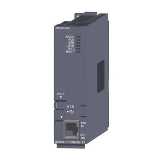
CHAPTER 2 PART NAMES CHAPTER 2 PART NAMES This chapter describes the name and application of each part of the C Controller module. Q24DHCCPU-V/-VG/-LS and Q26DHCCPU-LS <Q24DHCCPU-VG> /<Q24DHCCPU-LS>/ <Q24DHCCPU-V> <Q26DHCCPU-LS> Front cover Front cover [ Front ] [ Front ] *1 : The outline drawing for Q24DHCCPU-LS is shown. - Page 38 Pull the section indicated by "PULL" on the front cover by finger and open the cover as shown in the figure below. <Q24DHCCPU-VG> /<Q24DHCCPU-LS>/ <Q24DHCCPU-V> <Q26DHCCPU-LS> [ Front cover opened ] [ Front cover opened ] Q24DHCCPU-V Q24DHCCPU-LS *1 : The outline drawing for Q24DHCCPU-LS is shown.
- Page 39 CHAPTER 2 PART NAMES Description Name Q24DHCCPU-LS Q24DHCCPU-V Q24DHCCPU-VG Q26DHCCPU-LS SD memory card slot A slot into which an SD memory card is inserted on the C Controller module. RUN: Sets the C Controller module operation status to RUN. STOP: Sets the C Controller module operation status to STOP. MODE: Used for initialization and hardware diagnostics.
- Page 40 [ Side ] <Q24DHCCPU-VG>/<Q24DHCCPU-LS>/ <Q24DHCCPU-V> <Q26DHCCPU-LS> [ Bottom ] [ Bottom ]...
- Page 41 CHAPTER 2 PART NAMES Description Name Q24DHCCPU-LS Q24DHCCPU-V Q24DHCCPU-VG Q26DHCCPU-LS Battery Battery to retain the battery backup RAM and integral clock (RTC) data during power OFF. For connection of the battery lead wires. Battery connector pin (Lead wires are disconnected from the connector when shipping to prevent the battery from consuming.) Connector used for connection with an RS-232 compatible device.
- Page 42 (1) Indicator LEDs Description Name Q24DHCCPU-LS Q24DHCCPU-V Q24DHCCPU-VG Q26DHCCPU-LS Displays the operation status The C Controller module is in the RUN status. Any of the following states: • Executing the script file "STARTUP.CMD" Flash • Diagnosing hardware • Initializing modules The C Controller module is in the STOP/PAUSE status.
-
Page 43: Q12Dccpu-V
CHAPTER 2 PART NAMES Q12DCCPU-V MODE STOP RES. SEL. [ Front ] [ Front cover opened ] Q12DCCPU-V Name Description Indicator LEDs Page 43, (1) in this section. Displays settings and results at the time of initialization and hardware diagnostics. For the display during initialization, refer to the following. - Page 44 [ Side ] [ Bottom ] Q12DCCPU-V Name Description Battery Battery to retain the battery backup RAM and integral clock (RTC) data during power OFF. For connection of the battery lead wires. Battery connector pin (Lead wires are disconnected from the connector when shipping to prevent the battery from consuming.) RS-232 connector (CH3) Connector used for connection with an RS-232 compatible device.
- Page 45 CHAPTER 2 PART NAMES (1) Indicator LEDs Description Name Basic mode Extended mode Displays the operation status. The C Controller module is in the RUN status Flash Executing the script file "STARTUP.CMD" The C Controller module is in the STOP/PAUSE status MODE Displays the mode.
-
Page 46: Chapter 3 Specifications
CHAPTER 3 SPECIFICATIONS This chapter describes the specifications of the C Controller module. General Specifications The following indicates the general specifications. Item Specifications Operating ambient 0 to 55°C temperature Storage ambient -25 to 75°C temperature Operating ambient humidity 5 to 95%RH, non-condensing Storage ambient humidity Constant... -
Page 47: Performance Specifications
CHAPTER 3 SPECIFICATIONS Performance Specifications 3.2.1 Q24DHCCPU-V/-VG/-LS and Q26DHCCPU-LS The following indicates the performance specifications. Specifications Item Q24DHCCPU-V Q24DHCCPU-VG Q24DHCCPU-LS Q26DHCCPU-LS Hardware specifications (System CPU) – SH4A Hardware specifications (User CPU) – Endian format (Memory layout) Little endian ® Intel ATOM Processor Work RAM... - Page 48 Specifications Item Q24DHCCPU-LS Q24DHCCPU-V Q24DHCCPU-VG Q26DHCCPU-LS – User Ethernet port (CH1, CH2) Interface 10BASE-T/100BASE-TX/1000BASE-T Communication method Full- or half-duplex 10Mbps(10BASE-T)/100Mbps(100BASE-TX) Data transmission speed /1000Mbps(1000BASE-T) Transmission method Base band Maximum segment length 100m (distance between hub and node) Connector applicable to external wiring RJ45 Auto negotiation function (automatic recognition of communication speed/communication method)
- Page 49 CHAPTER 3 SPECIFICATIONS Specifications Item Q24DHCCPU-V Q24DHCCPU-VG, Q24DHCCPU-LS, Q26DHCCPU-LS RS-232 connector (CH3) specifications – Interface Compliant with RS-232 Communication method Full- or half-duplex Synchronization method asynchronous communication Transmission speed 9600, 14400, 19200, 28800, 38400, 57600, 115200 bps Transmission distance Up to 15m (49.21 feet) Start bit Data bit 7 / 8...
-
Page 50: Q12Dccpu-V
3.2.2 Q12DCCPU-V The following indicates the performance specifications Item Specifications Hardware specifications – Endian format (Memory layout) Little endian SH4A Work RAM 128 MB Standard RAM 0~3 MB Memory capacities Standard ROM 12 MB Battery backup RAM 512 KB~3.584 KB Software specifications –... - Page 51 CHAPTER 3 SPECIFICATIONS Item Specifications RS-232 connector (CH3) specifications – Interface Compliant with RS-232 Communication method Full- or half-duplex Synchronization method asynchronous communication Transmission speed 9600, 14400, 19200, 28800, 38400, 57600, 115200 bps Transmission distance Up to 15m (49.21 feet) Start bit Data bit 7 / 8...
-
Page 52: Device Specifications
Device Specifications This section describes the available devices. 3.3.1 Device list Described below are names of the available devices and range of use. Initial value Setting Classification Type Device name Number Range of use range of points Hexa Input 4096 point X0 to FFF decimal I/O device... -
Page 53: Device Description
CHAPTER 3 SPECIFICATIONS 3.3.2 Device Description Described below are the overview of the available devices. For details, refer to the following manual. QCPU User's Manual (Function Explanation, Program Fundamentals) Device Description I/O Device This is a device that corresponds to various user applications. Input is used for giving commands and data to the C Controller module from an *1,*2 external device such as a push-button switch, a selector switch, a limit switch,... -
Page 54: Chapter 4 Software Packages
CHAPTER 4 SOFTWARE PACKAGES This chapter describes each software package associated with the C Controller module. The following software packages can be used for the C Controller module. Version Software Q24DHCCPU Q26DHCCPU Q12DCCPU Setting/monitoring tools for the C Controller Version 4.01B Version 4.09K Version 4.03D Version 4.11M... -
Page 55: Chapter 5 Preparatory Procedure
CHAPTER 5 PREPARATORY PROCEDURE CHAPTER 5 PREPARATORY PROCEDURE This chapter describes the procedure to startup the C Controller module. Q24DHCCPU-V The following explains the start-up procedure for Q24DHCCPU-V. Start Module mounting Check field $QCPU User's Manual Mount the power supply module and the C Controller module on the base unit. (Hardware Design, Maintenance and Inspection) Power supply module ... - Page 56 From the previous page Check field System power-on $QCPU User's Manual (Hardware Design, Maintenance and Inspection) Power on after check that: • power supply wiring is properly arranged. • power supply voltage is within the operational range. Parameter setting Create a parameter. ...
-
Page 57: Q24Dhccpu-Vg
CHAPTER 5 PREPARATORY PROCEDURE Q24DHCCPU-VG The following explains the start-up procedure for Q24DHCCPU-VG. Start Module mounting Check field $QCPU User's Manual Mount the power supply module and the C Controller module on the base unit. (Hardware Design, Maintenance and Inspection) Power supply module •... - Page 58 From the previous page Check field Initial setting of modules $QCPU User's Manual Set each module switch. (Hardware Design, Maintenance and Inspection) $Manual for respective module • Set the RUN/STOP/MODE switch on the C Controller module to STOP. • Set the RUN/STOP/RESET switch on each CPU module to STOP. Page 35, CHAPTER 2 •...
-
Page 59: Q24Dhccpu-Ls And Q26Dhccpu-Ls
CHAPTER 5 PREPARATORY PROCEDURE Q24DHCCPU-LS and Q26DHCCPU-LS The following explains the start-up procedure for Q24DHCCPU-LS and Q26DHCCPU-LS. Start Module mounting Check field $QCPU User's Manual (Hardware Design, Maintenance and Inspection) Mount the power supply module and the C Controller module on the base unit. ... - Page 60 From the previous page Check field System power-on $QCPU User's Manual (Hardware Design, Maintenance and Inspection) Power on after check that: • power supply wiring is properly arranged. • power supply voltage is within the operational range. Parameter setting Create a parameter. ...
-
Page 61: Installation Procedure For Partner Operating System
CHAPTER 5 PREPARATORY PROCEDURE 5.3.1 Installation procedure for partner operating system The following explains the installation procedure for partner operating system. Start Check field Prepare the installation media Refer to the manual of the partner operating system, or consult the partner (operating system vendor). -
Page 62: Q12Dccpu-V
Q12DCCPU-V The following explains the start-up procedure for Q12DCCPU-V. Start Module mounting Check field $QCPU User's Manual Mount the power supply module and the C Controller module on the base unit. (Hardware Design, Maintenance and Inspection) Power supply module Page 116, CHAPTER 8 •... - Page 63 CHAPTER 5 PREPARATORY PROCEDURE From the previous page Check field System power-on $QCPU User's Manual (Hardware Design, Maintenance and Inspection) Power on after check that: • power supply wiring is properly arranged. • power supply voltage is within the operational range. Parameter setting Create a parameter.
-
Page 64: Chapter 6 Hardware Operations
CHAPTER 6 HARDWARE OPERATIONS This chapter describes the switch operations of the C Controller module. Initialization Q24DHC-V Q24DHC-VG Q24DHC-LS Q26DHC-LS Q12DC-V Described in this section is the initialization of the C Controller module. Initialization is useful in the following situations: •... -
Page 65: Q24Dhccpu-V/-Vg/-Ls And Q26Dhccpu-Ls
CHAPTER 6 HARDWARE OPERATIONS 6.1.1 Q24DHCCPU-V/-VG/-LS and Q26DHCCPU-LS (1) Initialization status Initialization brings the Q24DHCCPU-V/-VG/-LS and Q26DHCCPU-LS into the following status: (a) Default IP settingNote6.1 • The execution of the script file registered on the "/ROM" drive (standard ROM) is stopped. Note6.1 •... - Page 66 (2) Operating procedure (a) Preparation Before initializing the Q24DHCCPU-V/-VG/-LS and Q26DHCCPU-LS, take the steps listed below: Install the module. Install the power supply module and Q24DHCCPU-V/-VG/-LS and Q26DHCCPU-LS to the base unit. Insert the Q24DHCCPU-V/-VG/-LS and Q26DHCCPU-LS into the CPU slot. Do not install any module other than a power supply module and the Q24DHCCPU-V/-VG/-LS and Q26DHCCPU-LS.
- Page 67 CHAPTER 6 HARDWARE OPERATIONS (b) Initialization setting Perform the following operations to configure settings for initialization. Move the RESET/SELECT switch to the RESET position. Do not release the switch while pulling it down. Check that the LED goes off. Move the RUN/STOP/MODE switch to MODE position. Do not release the switch while pulling it down.
- Page 68 (d) Execution of initialization Perform the following operations to execute initialization. Move the RESET/SELECT switch to the RESET position. Do not release the switch while pulling it down. Check that the MODE LED goes off. Move the RESET/SELECT switch back to the center. Release the switch then it returns to its center position.
-
Page 69: Q12Dccpu-V
CHAPTER 6 HARDWARE OPERATIONS 6.1.2 Q12DCCPU-V (1) Initialization status Initialization brings the Q12DCCPU-V into the following status: (a) Default IP setting • The execution of the script file registered on the "/ROM" drive (standard ROM) is stopped. • The IP address of the Q12DCCPU-V is set to the default. Item Description Built-in Ethernet port CH1... - Page 70 (b) Initialization setting Perform the following operations to configure settings for initialization. Move the RESET/SELECT switch to the RESET position. Check that the MODE LED goes off. Move the RUN/STOP/MODE switch to MODE position. Do not release the switch while pulling it down. Move the RESET/SELECT switch back to the center.
- Page 71 CHAPTER 6 HARDWARE OPERATIONS (d) Execution of initialization Perform the following operations to execute initialization. Move the RESET/SELECT switch to the RESET position. Check that the MODE LED goes off. Move the RESET/SELECT switch back to the center. Check that the MODE LED turns on in orange. During initialization, RUN LED and USER LED are flashed.
-
Page 72: Change Of Operation Status (Run/Stop)
Change of Operation Status (RUN/STOP) You may use RUN/STOP/MODE switch operations to change the C Controller module operation status (RUN/STOP). For details of the operation status, refer to the following. Page 307, Section 17.2.3 RUN, STOP and PAUSE status operation processing ●... -
Page 73: Reset
CHAPTER 6 HARDWARE OPERATIONS Reset Reset is an operation to apply any parameter and/or user program change and reboot the entire system. The procedures to reset the C Controller system are described below. • Power cycle (power OFF ON) •... - Page 74 (b) Q12DCCPU-V Move the RESET/SELECT switch to the RESET position. Check that the MODE LED goes off. Move the RESET/SELECT switch back to the center. Check that the MODE LED turns on in orange. ● For the remote reset operation, refer to the following. ...
-
Page 75: Restarting User Cpu
CHAPTER 6 HARDWARE OPERATIONS Restarting User CPU Q12DC-V Q24DHC-V Q24DHC-VG Q24DHC-LS Q26DHC-LS User CPU restarting is an operation to apply the changes made in the user program while the system is running. You may restart the user CPU by operating U RST/P1/P2 switches. In addition, user CPU restarting is also possible from Setting/monitoring tools for the C Controller module or user program. - Page 76 (2) Setting method Set the following setting item to "Enable" through Setting/monitoring tools for the C Controller module. • "CCPU Parameter" <<System settings>> "Restart user CPU" (3) Methods There are 3 ways to execute user CPU restarting, which are described in the following pages. •...
-
Page 77: Hardware Diagnostics
CHAPTER 6 HARDWARE OPERATIONS Hardware Diagnostics Q24DHC-V Q24DHC-VG Q24DHC-LS Q26DHC-LS Q12DC-V Hardware diagnostics is a test to check the hardware within the C Controller module. Hardware diagnostics is useful in the following situations: • Initial operation • Troubleshooting During hardware diagnostics, do not power OFF or reset the C Controller system. Otherwise, the C Controller module may no longer be started up normally. - Page 78 (b) Q24DHCCPU-LS and Q26DHCCPU-LS Dot matrix LED Mode Diagnostic item Description display Diagnostic test of Mode 1 to Diagnoses in order of Mode 1 Mode 2 Mode 5 Mode 6. M-00 Mode 6 Battery backup RAM Checks test data by writing/reading/verifying them on the battery backup M-01 diagnostic test RAM.
- Page 79 CHAPTER 6 HARDWARE OPERATIONS (b) Necessary preparations for each diagnostics Before performing each hardware diagnostics test, take the steps listed below. • When executing Mode 0 Perform all preparation tasks for executing the following mode from 1 to 6. • When executing Mode 1 Back up all data in the standard ROM and battery backup RAM data.
- Page 80 (c) Test mode selection Perform the following operations to select a test mode to execute. Move the RESET/SELECT switch to the RESET position. Do not release the switch while pulling it down. Check that the LED goes off. Move the RUN/STOP/MODE switch to the MODE position. Do not release the switch while pulling it down.
- Page 81 CHAPTER 6 HARDWARE OPERATIONS (e) If the dot matrix LED shows other than "0000" The "ERR." LED starts flashing once the error is detected during diagnostics or setting. A value corresponding to the diagnostics for which the error occurred is displayed on the dot matrix LED. If the dot matrix LED is off and only "ERR."...
-
Page 82: Q12Dccpu-V
6.5.2 Q12DCCPU-V (1) Diagnostics types In the hardware diagnostics test, diagnostics on the following items are performed. 7-segment LED Mode Diagnostic item Description display Diagnostic test of Mode 1 to Conducts tests in the order from Mode 1 to Mode 6. Mode 6 ROM diagnostic test Reads the ROM data and performs error detection. - Page 83 CHAPTER 6 HARDWARE OPERATIONS (b) Necessary preparations for each diagnostics Before performing each hardware diagnostics test, take the steps listed below. • When executing Mode 0 Perform all preparation tasks for executing the following mode from 1 to 6. • When executing Mode 1 Back up all data in the standard ROM and battery backup RAM data.
- Page 84 (c) Test mode selection Perform the following operations to select a test mode to execute. Move the RESET/SELECT switch to the RESET position. Check that the MODE LED goes off. Move the RUN/STOP/MODE switch to the MODE position. Do not release the switch while pulling it down. Move the RESET/SELECT switch back to the center.
- Page 85 CHAPTER 6 HARDWARE OPERATIONS (e) If the 7-segment LED shows other than "00" The "ERR." LED starts flashing once the error is detected during diagnostics or setting. A value corresponding to the diagnostics for which the error occurred is displayed on the 7-segment LED. If the 7-segment LED is off and only "ERR."...
- Page 86 Memo...
- Page 87 PART 2 HARDWARE DESIGN, MAINTENANCE AND INSPECTION This section describes items related to hardware design, maintenance and inspection. CHAPTER 7 SYSTEM CONFIGURATION ........86 CHAPTER 8 INSTALLATION AND WIRING .
-
Page 88: Chapter 7 System Configuration
CHAPTER 7 SYSTEM CONFIGURATION This chapter describes the overall configuration, precautions for configuration and peripherals. Overall Configuration The overall configuration of the C Controller system is illustrated below. For a multiple CPU system ● Basic model QCPU ● Motion CPU ●... -
Page 89: Precautions For System Configuration
*4 : For applicable GOT models, refer to the following. Connection manuals for GOT2000 series (Mitsubishi Electric Products), (Non-Mitsubishi Electric Products 1), (Non-Mitsubishi Electric Products 2), (Microcomputer, MODBUS/Fieldbus Products, Peripherals) Connection manuals for GOT1000 series (Mitsubishi Electric Products), (Non-Mitsubishi Electric Products 1),... -
Page 90: Basic Configuration (Single Cpu System Configuration)
(3) Total current consumption The total current consumption for system configuration must not exceed the power supply module's rated output current of DC5V. For specifications of the power supply module, refer to the manual for respective modules. QCPU User's Manual (Hardware Design, Maintenance and Inspection) Basic Configuration (Single CPU System Configuration) Described in this section is the basic configuration with a C Controller module. - Page 91 CHAPTER 7 SYSTEM CONFIGURATION (2) Extension stage number setting To use 2 or more extension base units, it is necessary to set the extension base number by the extension base number setting connector on the extension base unit. When a C controller module is used, extension base number can be up to 7. Extension stage number setting Base number setting connector...
-
Page 92: Battery
7.3.3 Battery The batteries available for the C Controller module are listed below. (1) Specifications Model Item Q6BAT Q7BAT Type Manganese dioxide lithium primary battery Initial voltage 3.0V Nominal current 1800mAh 5000mAh capacity Battery life when stored Actual 5 years (room temperature) Battery life when used Page 487, Appendix 8 Lithium content... -
Page 93: Multiple Cpu System Configuration
CHAPTER 7 SYSTEM CONFIGURATION Multiple CPU System Configuration A multiple CPU system consists of two or more CPU modules mounted on a main base unit, and each CPU module controls I/O module(s) and/or intelligent function module(s) individually. For concepts of the multiple CPU system, refer to the following. QCPU User's Manual (Multiple CPU System) Motion CPU QCPU... -
Page 94: Combination Of Cpu Modules
7.4.2 Combination of CPU modules Described in this section is possible CPU module combination in the multiple CPU system by using a C Controller module. For combination of CPU modules for other than this product, refer to the manual for respective CPU module. –: Incompatible Number of CPUs that can be mounted as CPU No.2 or others Maximum... -
Page 95: Mounting Position
CHAPTER 7 SYSTEM CONFIGURATION 7.4.3 Mounting position The C Controller module can be mounted in the base unit CPU slot and slots 0 through 2. CPU Slot Slot 0 Slot 1 Slot 2 Slot No. (1) Parameter setting precautions (a) I/O assignment setting As the Q24DHCCPU-V/-VG/-LS and Q26DHCCPU-LS is 3-slot, set 2 slots at the right to "Empty"... - Page 96 (b) Number of CPUs setting The number of CPUs set in the Multiple CPU Setting in Parameter for Q24DHCCPU-V/-VG/-LS and Q26DHCCPU-LS is as follows: CPU module position Number of Number of CPU Slot Slot 0 Slot 1 Slot 2 CPU modules parameter CPUs Q24DHCCPU-V Q24DHCCPU-VG...
-
Page 97: Cpu Number
CHAPTER 7 SYSTEM CONFIGURATION 7.4.4 CPU number CPU numbers are allocated for identifying the CPU modules mounted on the main base unit in the multiple CPU system. CPU No.1 is allocated to the CPU slot, and CPU No.2, No.3 and No.4 are allocated to the right of the CPU No.1 in this order. -
Page 98: I/O Module/Intelligent Function Module
I/O Module/Intelligent Function Module This section describes I/O modules and intelligent function modules that can be used with the C Controller module. 7.5.1 Applicable modules Available I/O modules and intelligent function modules are listed below. The MELSEC-AnS/Q2AS series I/O modules and special function modules are not applicable. (For restrictions on the number of installations, refer to Page 87, Section 7.2) Restriction on Module type... - Page 99 CHAPTER 7 SYSTEM CONFIGURATION Restriction on Module type Model support version QD75M1, QD75MH1, QD75M2, QD75MH2, QD75M4, QD75MH4, QD74MH8, QD74MH16, QD70D4, – QD70D8, QD72P3C3, QD75P1N, QD75P2N, Positioning module QD75P4N, QD75D1N, QD75D2N, QD75D4N, QD73A1 QD75P1, QD75P2, QD75P4, QD75D1, QD75D2, Use the product of QD75D4, QD70P4, QD70P8 function version B or later.
- Page 100 EQGPIB – For applicable GOT models, refer to the following. Connection manuals for GOT2000 series (Mitsubishi Electric Products), (Non-Mitsubishi Electric Products 1), (Non-Mitsubishi Electric Products 2), (Microcomputer, MODBUS/Fieldbus Products, Peripherals) Connection manuals for GOT1000 series (Mitsubishi Electric Products),...
-
Page 101: Operating Precautions
CHAPTER 7 SYSTEM CONFIGURATION 7.5.2 Operating precautions This section explains the precautions for using I/O modules and intelligent function modules.For details of precautions, refer to the manual for respective modules. The instructions dedicated to intelligent function modules cannot be used for C Controller modules. (1) Precautions for using a CC-Link IE Controller Network module The following restrictions are applied to the CC-Link IE controller network module controlled by the C Controller module. - Page 102 (3) Precautions for using the CC-Link IE Field Network master/local module The following restrictions are applied to the CC-Link IE field network master/local module controlled by the C Controller module. • The module cannot be used as a relay station for the data link transfer function or the routing function. When using either of these functions, use a CC-Link IE field network master/local module controlled by a programmable controller CPU as a relay station.
- Page 103 CHAPTER 7 SYSTEM CONFIGURATION (7) Precautions on interrupt processing Interrupts are used for communications of the C Controller module. These communications may be disabled if a program that disables interrupts is executed. Also, communication may become slow if a program with frequent interrupts is executed. (8) Precautions for using a MES interface module and Web server module The following restrictions are applied to the MES interface module and Web server module controlled by the C Controller module.
-
Page 104: Peripheral Configuration
Peripheral Configuration User program Personal computer for development environment maintenance (Personal computer) • Telnet function MES server SNTP server • CW Workbench • FTP function Superior communication network General-purpose USB device analog display SD memory card/CompactFlash card Various networks via the network module HMI (GOT) Setting/monitoring tools for the C Controller module... -
Page 105: Sd Memory Card
(1) Available SD memory cards For "-LS", consult with the partner (operating system vendor). Available Mitsubishi Electric Corporation's SD memory cards are as listed below: • NZ1MEM-2GBSD (memory capacity: 2GB) • NZ1MEM-4GBSD (memory capacity: 4GB) • NZ1MEM-8GBSD (memory capacity: 8GB) •... -
Page 106: Compactflash Card
Q24DHC-V Q12DC-V A CompactFlash card can be mounted to a Q12DCCPU-V. (1) Available CompactFlash cards Available Mitsubishi Electric Corporation's CompactFlash cards are as listed below: • QD81MEM-512MBC (memory capacity: 512MB) • QD81MEM-1GBC (memory capacity: 1GB) • QD81MEM-2GBC (memory capacity: 2GB) •... - Page 107 CHAPTER 7 SYSTEM CONFIGURATION (5) Measures against static electricity for commercially available CompactFlash cards in compliance with the EMC directives The C Controller system may be affected by static electricity discharged to a commercially available CompactFlash card. The following explains an example of static electricity countermeasures for commercially available CompactFlash card.
-
Page 108: Connection With Usb Device
7.6.3 Connection with USB device Q24DHC-V Q24DHC-VG Q24DHC-LS Q26DHC-LS Q12DC-V (1) Q24DHCCPU-V USB device(s) compliant with the USB Mass Storage Class standard can be connected to the Q24DHCCPU-V. ●C Controller module ● USB device ● USB cable (2) Q24DHCCPU-VG In addition to USB device compliant with the USB Mass Storage Class standard, a mouse and a keyboard can be connected to Q24DHCCPU-VG. - Page 109 CHAPTER 7 SYSTEM CONFIGURATION (3) Q24DHCCPU-LS and Q26DHCCPU-LS For details on USB device can be connected to Q24DHCCPU-LS and Q26DHCCPU-LS, consult the partner (operating system vendor). (4) Connection via USB connector For "-LS", consult with the partner (operating system vendor). Use the USB connector USB1 for connection.
- Page 110 (c) Connectable keyboard An OADG-compliant Japanese 106-key keyboard and English 101-key keyboard can be connected. Since a Japanese keyboard is enabled as standard, execute one of the following commands with “STARTUP.CMD” or the Telnet connection according to the keyboard to be used, and switch the setting. The changed setting will be enabled at the time of next startup of the display application.
-
Page 111: Connection With Hmi (Got)
Ethernet cable For applicable GOT models, refer to the following. Connection manuals for GOT2000 series (Mitsubishi Electric Products), (Non-Mitsubishi Electric Products 1), (Non-Mitsubishi Electric Products 2), (Microcomputer, MODBUS/Fieldbus Products, Peripherals) Connection manuals for GOT1000 series (Mitsubishi Electric Products), (Non-Mitsubishi Electric Products 1),... - Page 112 (For GOT bus connection, occupy one the extension base (16 points x 10 slots).) For details of the GOT, refer to the following. Connection manuals for GOT2000 series (Mitsubishi Electric Products), (Non-Mitsubishi Electric Products 1), (Non-Mitsubishi Electric Products 2), (Microcomputer, MODBUS/Fieldbus Products, Peripherals) ...
-
Page 113: Connection With Personal Computer
CHAPTER 7 SYSTEM CONFIGURATION 7.6.5 Connection with Personal computer Q24DHC-V Q24DHC-VG Q24DHC-LS Q26DHC-LS Q12DC-V A Personal computer can be connected to the C Controller module as illustrated below. • Connection via USB connector • Connection via the Ethernet port • Connection via the CPU module by the multiple CPU system •... - Page 114 (1) Connection to user program development environment, Personal computer for maintenance, and superior control servers, etc. For "-LS", consult with the partner (operating system vendor). The following personal computer can be connected using the user Ethernet port (CH1 and CH2)/built-in Ethernet port (CH1 and CH2).
- Page 115 Connection manuals for GOT2000 series (Mitsubishi Electric Products), (Non-Mitsubishi Electric Products 1), (Non-Mitsubishi Electric Products 2), (Microcomputer, MODBUS/Fieldbus Products, Peripherals) Connection manuals for GOT1000 series (Mitsubishi Electric Products), (Non-Mitsubishi Electric Products 1), (Non-Mitsubishi Electric Products 2), (Microcomputer, MODBUS Products, Peripherals)
-
Page 116: Connection With Other Peripherals (C Controller Module, Etc.)
7.6.6 Connection with other peripherals (C Controller module, etc.) Q24DHC-V Q24DHC-VG Q24DHC-LS Q26DHC-LS Q12DC-V The C Controller module can be connected with other C Controller modules and/or various network peripherals in the device (internal microcomputers, etc.) by using the following methods: •... - Page 117 CHAPTER 7 SYSTEM CONFIGURATION (3) Connection with a general-purpose analog RGB display Note7.1 For "-LS", consult with the partner (operating system vendor). Use the analog RGB output connector for connection. For specifications and wiring of analog RGB output connector, refer to the following. Page 131, Section 8.7.3 (a) Precautions for connection with a general-purpose analog RGB display •...
-
Page 118: Chapter 8 Installation And Wiring
CHAPTER 8 INSTALLATION AND WIRING This chapter describes the installation and wiring procedures for C Controller module and other optional products. Installation Environment and Installation Position For precautions for installation environment and installation position, refer to the following. QCPU User's Manual (Hardware Design, Maintenance and Inspection) Installation and Removal of Module The following explains how to install and remove a C Controller module. - Page 119 CHAPTER 8 INSTALLATION AND WIRING (1) Installation to base unit Base unit Securely insert the module fixing projection into the module fixing hole so that the latch is not misaligned. Base unit Module Module fixing mounting lever hook Using the module fixing Module fixing hole as a supporting point, projection...
- Page 120 (2) Removal from base unit Support the module with both hands and securely press the module fixing hook with your finger. Lifting Push Pull the module straight toward you supporting it at its bottom while pressing the module Module fixing fixing hook hook Module connector...
-
Page 121: Battery Installation
CHAPTER 8 INSTALLATION AND WIRING Battery Installation This section describes the procedures of installing a battery into the C Controller module. The battery connector is disconnected from the battery before shipping. Connect the battery connector before use. For operations without any battery, use the battery less drive function ( Page 190, Section 11.11). (1) Q6BAT battery installation procedure Open the C controller module Lead wire of... -
Page 122: Inserting And Removing An Sd Memory Card
Inserting and Removing an SD Memory Card Q24DHC-V Q24DHC-VG Q24DHC-LS Q26DHC-LS Q12DC-V This section describes the procedures of inserting/removing an SD memory card into the C Controller module. For "-LS", consult with the partner (operating system vendor). ● Before handling an SD memory card, touch a grounded metal object to discharge the static electricity from the human body. Failure to do so may cause failure of the SD memory card or malfunction. - Page 123 CHAPTER 8 INSTALLATION AND WIRING (2) Removal procedure Pull the section labeled as "PULL" on the cover to open the cover. Open both right and left covers. Move the RESET/SELECT switch to the SELECT position. Do not release the switch while pulling it down. Check that the SD CARD LED start flashing.
-
Page 124: Installing/Uninstalling And Unmounting A Compactflash Card
Installing/uninstalling and unmounting a CompactFlash card Q24DHC-V Q24DHC-VG Q24DHC-LS Q26DHC-LS Q12DC-V This section describes the procedures of inserting/removing a CompactFlash card into the C Controller module. ● Before handling a CompactFlash card, touch a grounded metal object to discharge the static electricity from the human body. - Page 125 CHAPTER 8 INSTALLATION AND WIRING (2) Uninstallation procedure Pull the section labeled as "PULL" on the front cover to open the cover. Move the RESET/SELECT switch to the SELECT position. Do not release the switch while pulling it down. Check that the CF CARD LED start flashing. Keep the switch at the SELECT side while flashing the LED.
-
Page 126: Inserting/Removing And Unmounting A Usb Mass Storage Class Standard Compliant
Inserting/removing and Unmounting a USB Mass Storage Class Standard Compliant Device Q12DC-V Q24DHC-V Q24DHC-VG Q24DHC-LS Q26DHC-LS This section explains how to insert/remove a device compliant with the USB Mass Storage Class standard into/from C Controller module. For "-LS", consult with the partner (operating system vendor). -
Page 127: Cabling
CHAPTER 8 INSTALLATION AND WIRING Cabling 8.7.1 USB cabling Q24DHC-V Q24DHC-VG Q24DHC-LS Q26DHC-LS Q12DC-V Described in this section are the specifications and wiring of compatible USB cables. (1) USB connector (a) Q24DHCCPU-V/-VG/-LS and Q26DHCCPU-LS There are 2 types of USB connectors: USB1 and USB2. Use them accordingly to peripherals to be connected. USB connector Connection destination USB1... - Page 128 (3) USB cable fall-off prevention (Q24DHCCPU-V/-VG/-LS and Q26DHCCPU-LS) USB cable(s) can be fixed to the C Controller module enclosure with a fixing band (recommended specifications: Width: 6-9 mm and Thickness: 1mm or less). Procedure Figure Description A through hole for a fixing band is prepared next to the PCI ®...
-
Page 129: Ethernet Wiring
CHAPTER 8 INSTALLATION AND WIRING 8.7.2 Ethernet wiring Q24DHC-V Q24DHC-VG Q24DHC-LS Q26DHC-LS Q12DC-V Described in this section are the specifications and wiring of compatible twisted pair cables. (1) Ethernet port (a) Q24DHCCPU-V/-VG/-LS and Q26DHCCPU-LS There are 2 types of Ethernet port: user Ethernet port (CH1 and CH2) and system Ethernet port (S CH1). Use them accordingly to peripherals to be connected. - Page 130 (2) Twisted pair cable Specifications of cables that can be used for connection with peripherals by using the user Ethernet ports (CH1 and CH2), system Ethernet port (S CH1), and Built-in Ethernet ports (CH1 and CH2) are described in the table below.
- Page 131 CHAPTER 8 INSTALLATION AND WIRING (3) Setting an IP address To use the Ethernet port(s), it is necessary to set an IP address. You may set an IP address by using parameters by /monitoring tools for the C Controller module. Setting ●...
- Page 132 (b) Precautions for IP address setting For "-LS", consult with the partner (operating system vendor). The network portion of the IP address must be the same in both the destination device to connect and the user Ethernet port or Built-in Ethernet port. CH1 and CH2 of user Ethernet port and built-in Ethernet port must have different network portions in their IP addresses.
-
Page 133: Analog Rgb Output Cabling
CHAPTER 8 INSTALLATION AND WIRING 8.7.3 Analog RGB output cabling Q24DHC-V Q12DC-V Q24DHC-VG Q24DHC-LS Q26DHC-LS Described in this section are the specifications and wiring of compatible RGB cables. (1) Analog RGB output connector The analog RGB output connector is located at the bottom face of the module. Analog RGB output connector Connection destination General-purpose RGB display... -
Page 134: Rs-232 Cabling
To use a 9-pin D-sub connector RS-232 cable, use an optional RS-232 conversion connector cable. Cable model Maker name Model name RS-232 conversion cable Mitsubishi Electric Corporation Q12DCCPU-CBL (Round connector 9-pin D-sub connector) Use the following product as a connection cable connector. Connector type... - Page 135 CHAPTER 8 INSTALLATION AND WIRING (2) Precautions Precautions for use of RS-232 cables: • Ground the shield of the RS-232 cable to a single point. • Bend radius of the cable portion near the connector should be "cable's outside diameter 4" or more. •...
-
Page 136: Chapter 9 Maintenance And Inspection
CHAPTER 9 MAINTENANCE AND INSPECTION This chapter explains items you should perform routinely or at regular intervals to ensure normal and the best conditions of the C Controller module. Daily Inspection The following table lists the items to be inspected daily. Item Inspection Criterion... -
Page 137: Periodical Inspection
CHAPTER 9 MAINTENANCE AND INSPECTION Periodical Inspection This section explains the items to be inspected once or twice every six months or every year. Note that these inspections are required when the system is moved or modified including re-wiring. Item Inspection Criterion Action... -
Page 138: Battery Replacement Procedure
Battery Replacement Procedure Before the C Controller module battery reaches the limit of its life, replace it by the following procedure. Before removing the battery, turn on the C Controller system power for 10 minutes or more. Data will be backed up by the capacitor for a while after removing the battery. However, quickly replace the battery since the data may be cleared if it takes more than the following guaranteed time. -
Page 139: Standard Rom Life
CHAPTER 9 MAINTENANCE AND INSPECTION Standard ROM Life Q24DHC-LS Q26DHC-LS Q24DHC-V Q24DHC-VG Q12DC-V Described in this section is the standard ROM lifetime. Do not write files other than parameter and script files to the standard ROM. If you need to do so, write files into an SD memory card or CompactFlash card. (1) Standard ROM life •... - Page 140 Memo...
- Page 141 PART 3 FUNCTION This section describes the functions available for the C Controller module. CHAPTER 10 FUNCTION LIST ......... . . 140 CHAPTER 11 BASIC FUNCTIONS.
-
Page 142: Chapter 10 Function List
CHAPTER 10 FUNCTION LIST This chapter explains the C Controller module functions. (1) Basic functions : Supported : Not supported : Supported with restrictions CPU module Function Description Q24DHC Reference Q26DHC Q12DC I/O module, intelligent function module, and interrupt module control function I/O module and intelligent Controls I/O modules or intelligent Page 146,... - Page 143 CHAPTER 10 FUNCTION LIST CPU module Function Description Q24DHC Reference Q26DHC Q12DC Controls the execution status (RUN/ STOP/PAUSE) of the C Controller Page 163, Remote operation function module from its user program or Section 11.5 development environment. Creates a device such as a Page 169, Device function programmable controller CPU in work...
- Page 144 : Supported : Not supported : Supported with restrictions CPU module Function Description Q24DHC Reference Q26DHC Q12DC Refresh function Sets the refresh cycle used by the C Page 170, Refresh cycle setting Controller module. Section 11.7 Performs refreshing automatically between the devices of the C Controller Page 171, Data refresh function...
-
Page 145: Part 3 Function
CHAPTER 10 FUNCTION LIST (2) Functions accessed via Ethernet ports : Supported : Not supported : Supported with restrictions CPU module Function Description Q24DHC Reference Q26DHC Q12DC User Ethernet port/Built-in Ethernet port function Communicates with Ethernet device Communication function (development personal computer, etc.) Page 192, with peripheral devices and user Ethernet port, or built-in... - Page 146 (3) Functions accessed via a network module : Supported : Not supported : Supported with restrictions CPU module Function Description Q24DHC Reference Q26DHC Q12DC Cyclic transmission function From the user program of the C Controller module, accesses to Access function by link device(s) of the C Controller module.
- Page 147 CHAPTER 10 FUNCTION LIST (4) Functions used by multiple CPU system : Supported : Not supported : Supported with restrictions CPU module Function Description Q24DHC Reference Q26DHC Q12DC Data communications using CPU shared memory Transmits/receives data by using Data communications using automatic refresh between the C Page 256, auto refresh...
-
Page 148: Chapter 11 Basic Functions
CHAPTER 11 BASIC FUNCTIONS This chapter explains the basic functions of the C Controller module. Remark Check details of each function from the following functions of Setting/monitoring tools for the C Controller module. • [Help] [Function help] [C Controller module function help] 11.1 I/O Module and Intelligent Function Module Access Function... -
Page 149: Switch Settings For I/O And Intelligent Function Modules
CHAPTER 11 BASIC FUNCTIONS (2) Function In the table below, functions used for I/O modules and intelligent function modules are listed. Function name Function QBF_X_In_BitEx Reads out input signals (X) in bit (1 point). QBF_X_In_WordEx Reads out input signals (X) in word (16 points). QBF_Y_Out_BitEx Outputs output signals (Y) in bit (1 point). -
Page 150: Interrupt From Intelligent Function Module And Interrupt Module
11.1.3 Interrupt from intelligent function module and interrupt module Q24DHC-LS Q26DHC-LS Q24DHC-V Q24DHC-VG Q12DC-V The C Controller module can resume the user program that has been in the interrupt event waiting status when an interrupt from the intelligent function module or interrupt module occurs. Remark This section describes operations on the C Controller module. - Page 151 CHAPTER 11 BASIC FUNCTIONS C Controller module (User program) 1) QBF_WaitUnitEvent function 2) Waiting for an interrupt event 4) User program resumed Interrupt event notification 3) Interrupt issue (3) Function The following are functions used in interrupts from the intelligent function module or interrupt module. Function name Function Waits for an interrupt event notification issued when an interrupt occurs from an intelligent...
-
Page 152: Input Response Time Selection (I/O Response Time)
11.1.4 Input response time selection (I/O response time) Q24DHC-V Q24DHC-VG Q24DHC-LS Q26DHC-LS Q12DC-V The input response time can be changed for each Q series module. (1) Applicable modules and setting contents The following table shows the modules whose input response time can be changed and time options for them. Module whose input response time can be changed Type Option... -
Page 153: Output (Y) Status Setting For Switching Stop To Run
CHAPTER 11 BASIC FUNCTIONS 11.1.5 Output (Y) status setting for switching STOP to RUN Q24DHC-V Q24DHC-VG Q24DHC-LS Q26DHC-LS Q12DC-V When the C Controller module status is switched from RUN to STOP, the output data (Y) in the RUN status are saved in the C Controller module and actual outputs are all turned off. -
Page 154: Error Time Output Mode Setting
(b) Operations in case where writing operation to output (Y) is set in the data refresh settings Regardless of the parameter "Output mode at STOP to RUN" (Previous State/Recalculate), the output (Y) is refreshed by the data refresh right after the status is changed from STOP to RUN. •... -
Page 155: Hardware Error Time Cpu Operation Mode Setting
CHAPTER 11 BASIC FUNCTIONS 11.1.7 Hardware error time CPU operation mode setting Q24DHC-V Q24DHC-VG Q24DHC-LS Q26DHC-LS Q12DC-V This setting determines whether to stop or continue the output (Y) from the C Controller module and writing to the buffer memory if a hardware error occurs in an intelligent function module or interrupt module. (1) Setting method For this setting, use the following functions in Setting/monitoring tools for the C Controller module. -
Page 156: Self-Diagnostic Function
11.2 Self-Diagnostic Function Q24DHC-V Q24DHC-VG Q24DHC-LS Q26DHC-LS Q12DC-V The self-diagnostic function allows the C Controller module to detect its own error during operation, preventing a malfunction and providing preventive maintenance. (1) Self-diagnostics timing When an error occurs at power-on of the C controller module or during RUN/STOP of the C controller module, an error is detected and displayed, and the operation of the C controller module will be stopped by the self-diagnostic function. - Page 157 CHAPTER 11 BASIC FUNCTIONS (b) CPU operation mode Whether to stop or continue the output (Y) from the user program and writing to the buffer memory can be selected for the module. For this setting, use the following functions in Setting/monitoring tools for the C Controller module. •...
- Page 158 (5) Self-diagnostic function list The following shows the self-diagnostic functions available during normal operation. CPU module LED status Item Error message Diagnostic timing status ERR. Hardware error MAIN CPU DOWN • Any time Stop Flash CPU error RAM check RAM ERROR •...
- Page 159 CHAPTER 11 BASIC FUNCTIONS CPU module LED status Item Error message Diagnostic timing ERR. status Parameter error Parameter setting check PARAMETER ERROR • At power-on, at reset Stop Flash Link parameter error LINK PARA.ERROR • At power-on, at reset Stop Flash Intelli-parameter error SP.PARA.ERROR...
-
Page 160: Watchdog Timer (Wdt)
(6) Clearing errors A C Controller module can clear only continuation errors. (a) Error clear procedure To clear errors, complete the following procedure. Eliminate the reason for the error. Perform one of the following operations or processes.Note11.2 • Perform the error clear operations in [Diagnostics] [CCPU diagnostics] <<CCPU diagnostics>>... - Page 161 CHAPTER 11 BASIC FUNCTIONS (1) Conditions for watchdog timer time out • System watchdog timer Times out when the system processing has been suspended for a long time, for reasons such as C Controller module hardware error and interrupt program execution, etc. •...
-
Page 162: Clock Function
11.4 Clock Function Q24DHC-V Q24DHC-VG Q24DHC-LS Q26DHC-LS Q12DC-V This function serves as the integral clock (RTC: Real Time Clock) in the C Controller module. Clock data of the integral clock can be set and checked (read out) from etting/monitoring tools for the C Controller module and the user program. - Page 163 CHAPTER 11 BASIC FUNCTIONS (3) Changing and reading clock data (a) Changing clock data There are 2 ways to change clock data as described below. • Using Setting/monitoring tools for the C Controller module Select [Online] [Set Clock] to change the clock data. •...
- Page 164 (5) Multiple CPU clock synchronization function The multiple CPU clock synchronization function allows clock data synchronization with CPU No.1 when the C Controller module is set as CPU No.2, No.3, or No.4 in a multiple CPU system. Clock data will be received from CPU No.1 at the following timing. •...
-
Page 165: Remote Operation Function
CHAPTER 11 BASIC FUNCTIONS 11.5 Remote Operation Function Q24DHC-V Q24DHC-VG Q24DHC-LS Q26DHC-LS Q12DC-V The remote operation function controls the operation status of the C Controller module or a programmable controller CPU from the user program or Setting/monitoring tools for the C Controller module. Use the dedicated function library for control by the user program. - Page 166 (c) Methods for remote RUN/STOP There are the following 2 different ways to execute remote RUN/STOP. • Using Setting/monitoring tools for the C Controller module [Online] [Remote Operation] • Using user program Execute a bus interface function (QBF_ControlEx) to perform remote RUN/STOP. The following shows the function(s) used for remote RUN/STOP.
- Page 167 CHAPTER 11 BASIC FUNCTIONS (2) Remote PAUSE The remote PAUSE is a control from the user program or Setting/monitoring tools for the C Controller module, by which the C Controller module can be placed in the PAUSE status with its RUN switch set to RUN. (a) Application The remote PAUSE is useful in process control, for example, to keep the ON status of output (Y) set in the RUN status even if the C Controller module status is changed from RUN to PAUSE.
- Page 168 (3) Remote RESET The remote RESET is a control from the user program or Setting/monitoring tools for the C Controller module, by which the C Controller module or programmable controller CPU can be reset when it is in the STOP status. (a) Application The C Controller module or programmable controller CPU can be remotely reset when an error occurs in the place where direct control of the switch on the CPU module is not available.
- Page 169 CHAPTER 11 BASIC FUNCTIONS (d) Methods for remote RESET There are the following 2 different ways to execute remote RESET. • Using Setting/monitoring tools for the C Controller module [Online] [Remote Operation] • Using user program Execute a bus interface function (QBF_Reset) to perform remote RESET. The following shows the function(s) used for remote RESET.
- Page 170 (4) Relation between remote operation and RUN/STOP status This section explains the relation between the remote operations and the switch setting of the C Controller module. (a) Relation between remote operation and RUN/STOP status of C Controller module Remote operation Switch STOP PAUSE...
-
Page 171: Device Function
CHAPTER 11 BASIC FUNCTIONS 11.6 Device Function Q24DHC-V Q24DHC-VG Q24DHC-LS Q26DHC-LS Q12DC-V Creates a device such as a programmable controller CPU in work RAM on the C Controller module. (1) Device list The following shows the device that can be created, initial values and setting range. Default value Type Device name... -
Page 172: Refresh Function
11.7 Refresh Function Q24DHC-V Q24DHC-VG Q24DHC-LS Q26DHC-LS Q12DC-V Refresh function automatically reads/writes device data of the C Controller module to the set area in a cycle. There are following 2 types of refresh function in the C Controller module. Function Description Reference Perform refreshing between the devices of the C Controller module and the data... -
Page 173: Data Refresh Function
CHAPTER 11 BASIC FUNCTIONS 11.7.1 Data refresh function Q12DC-V Q24DHC-V Q24DHC-VG Q24DHC-LS Q26DHC-LS This function performs refreshing automatically between the devices of the C Controller module (X, Y, buffer memory) and the data refresh memory. Also, it issues an interrupt event when the data refresh memory value meets the specified condition. C Controller module Device (setting No.1) Device (setting No.2) - Page 174 (1) Setting method For this setting, use the following functions in Setting/monitoring tools for the C Controller module. • Project view "Parameter" "CCPU Parameter" <<Data refresh settings>> The number of points available for data refresh settings is up to 48K words. (2) Data refresh time The following indicates formulas to obtain time required for data refreshing.
- Page 175 CHAPTER 11 BASIC FUNCTIONS (4) Interrupt event issuance condition The following indicates conditions where an interrupt event can be issued. Detection Word device setting Device Interrupt condition Method value Interrupts when ON Level detect Interrupts when OFF Interrupts when rising Edge detect Bit device Interrupts when falling...
- Page 176 (c) Interrupt event issuance timing The data refresh interrupt event is issued in the timing of data refresh cycle. For details, refer to the following. Page 175, Section 11.7.3 (d) When an interrupt event has already been notified at execution of the C Controller module dedicated function (CCPU_WaitDataRefreshEvent function) For "-LS", consult with the partner (operating system vendor).
-
Page 177: Link Refresh Function
CHAPTER 11 BASIC FUNCTIONS 11.7.2 Link refresh function Q24DHC-V Q24DHC-VG Q24DHC-LS Q26DHC-LS Q12DC-V This function performs refreshing automatically between the devices of the C Controller module (B and W) and the link device of the network module. For details of link refresh, refer to the following. ... -
Page 178: Security Function
(3) Refresh time check The actual refresh time values (maximum, minimum and current values) while the C Controller system is running can be checked by using Setting/monitoring tools for the C Controller module. • [Diagnostics] [CCPU diagnostics] <<CCPU diagnostics>> "Refresh information" (a) Refresh time From "Refresh time"... -
Page 179: Access Authority Setting Function
CHAPTER 11 BASIC FUNCTIONS 11.8.1 Access authority setting function Q24DHC-V Q24DHC-VG Q24DHC-LS Q26DHC-LS Q12DC-V This function restricts operations and access to C Controller module by setting the access authority and lockout setting for each user account. *1 : Lockout setting is a function to limit the allowed number of account authentication failures in a row. If the number is exceeded, authentication is locked out for a certain period of time to prevent brute force attacks by unauthorized users. - Page 180 (1) Setting method For this setting, use the following functions in Setting/monitoring tools for the C Controller module. • Project view "Parameter" "CCPU Parameter" <<Account settings>> Up to 16 accounts can be created. (2) Factory account settings The following shows factory account settings of Setting/monitoring tools for the C Controller module.
-
Page 181: Individual Identification Function
CHAPTER 11 BASIC FUNCTIONS 11.8.2 Individual identification function Q24DHC-V Q24DHC-VG Q24DHC-LS Q26DHC-LS Q12DC-V This function prevents creation of unauthorized copy system (imitation) of the C Controller module. The C Controller module can read the individual identification information by accessing to a certain memory. User program(s) that is not activated by the other C Controller modules can be created by the user program by implementing the authentication function (activation function) that utilizes the individual identification information. - Page 182 (b) Flowchart Illustrated below is an example of the sequential processing flow chart. Individual identification information read-out Acquire PCI bus No., PCI device No., and PCI function No. Acquire the base address. Calculate the read register (EERD) address. Set the read address. (Initial value is "0000 ") Turn the START bit ON.
- Page 183 CHAPTER 11 BASIC FUNCTIONS (c) Sample program For "-LS", consult with the partner (operating system vendor). Illustrated below is an example of the sequential processing program. /* Individual identification information read-out processing */ #include <vxWorks.h> #include "pciConfigLib.h" #include <taskLib.h> void readIdentify(void){ /* Variable declaration */ unsigned short Identify[3];...
- Page 184 (2) Q12DCCPU-V (a) Read-out method Described below is the procedure to read the individual identification information. Read the individual identification information. The value of the individual identification information is stored in the memory address (0xA00BFFF4 to 0xA00BFFFF) as follows. Example) The individual identification information is '00:26:92:1E:8F:F0:00:26:92:1E:8F:F1' Memory Address 0xA00BFFF0 (b) Sample program Illustrated below is an example of the sequential processing program...
-
Page 185: File Access Restriction Function
CHAPTER 11 BASIC FUNCTIONS 11.8.3 File access restriction function Q24DHC-LS Q26DHC-LS Q24DHC-V Q24DHC-VG Q12DC-V This function restricts accesses to prevent unauthorized editing on files stored on the standard ROM, standard RAM, or work RAM (when RAM drive is used). By setting file attributes (a system file attribute and/or a hidden file attribute) to files under the memories described below, accesses to the files are restricted, and thus the falsifications by unauthorized users or file leaks can be prevented. - Page 186 (b) Checking file attribute Use the ll() command to check the file attribute. The following explains how to identify the file attribute. drwxrwxrSH H: Indicates the hidden file attribute is specified. x: Indicates the hidden file attribute is not specified. S: Indicates the system file attribute is specified.
-
Page 187: Service Setting Function
CHAPTER 11 BASIC FUNCTIONS 11.8.4 Service setting function Q24DHC-V Q24DHC-VG Q24DHC-LS Q26DHC-LS Q12DC-V This function sets the services status (enable/disable) operated on the C Controller module. By restricting the service which can be performed, accessing from an unexpected user can be prevented. (1) List of services : Supported : Not supported CPU module... - Page 188 (2) Setting method Set the settings with the following function in Setting/monitoring tools for the C Controller module. • Project view "Parameter" "CCPU Parameter" <<Security settings>> "Service settings" (3) Default service settings The settings become the default settings when the module is initialized. (a) Q24DHCCPU-V/-VG/-LS and Q26DHCCPU-LS All service settings are enabled.
-
Page 189: Event History Collection Function
CHAPTER 11 BASIC FUNCTIONS 11.9 Event History Collection Function Q24DHC-V Q24DHC-VG Q24DHC-LS Q26DHC-LS Q12DC-V Up to 500 events that occurred in the C Controller system will be registered as event history with occurrence time. If the number of event history items exceeds 500, the oldest event is deleted. For this setting, use the following functions in Setting/monitoring tools for the C Controller module. -
Page 190: Analog Rgb Port Display Function
(4) Precautions If the battery less drive is enabled, event history is cleared at power OFF or reset. Backup any necessary event history to the personal computer by using Setting/monitoring tools for the C Controller module. For details of battery less drive, refer to the following. ... - Page 191 CHAPTER 11 BASIC FUNCTIONS (2) Resolution setting Execute one of the commands below with “STARTUP.CMD” or the Telnet connection to switch the screen display. The changed setting will be enabled at the time of next startup of the display application. For more information on the supported resolution, refer to the following section.
-
Page 192: Battery Less Drive
11.11 Battery Less Drive Q24DHC-V Q24DHC-VG Q24DHC-LS Q26DHC-LS Q12DC-V This function operates the C Controller module without battery. The battery less drive function can improve the maintainability by establishing a system requiring no battery replacement. Data listed below are all initialized by powering ON or resetting C Controller system with the battery removed. Configure the settings again. - Page 193 CHAPTER 11 BASIC FUNCTIONS (1) Setting method For this setting, use the following functions in Setting/monitoring tools for the C Controller module. • Project view "Parameter" "CCPU Parameter" <<I/O assignment settings>> "Switch Settings" Set the b1 of the "Switch3" in the slot connected with the C Controller module to "ON". (Doing this to the other CPU slots, the setting is ignored.) (2) Precautions (a) Battery error...
-
Page 194: Chapter 12 Functions Accessed Via Ethernet Ports
CHAPTER 12 FUNCTIONS ACCESSED VIA ETHERNET PORTS This chapter describes the communication with peripherals, Telnet function and FTP client function. When using Q12DCCPU-V, consider the terms as shown in the following table. Before After Q24DHCCPU-V/-VG/-LS Q12DCCPU-V Q26DHCCPU-LS User Ethernet port (CH1 and CH2) Built-in Ethernet port (CH1 and CH2) System Ethernet port (S CH1) 12.1... - Page 195 CHAPTER 12 FUNCTIONS ACCESSED VIA ETHERNET PORTS (1) Setting method For this setting, use the following functions in Setting/monitoring tools for the C Controller module. <Q24DHCCPU-V/-VG> • Project view ”Parameter" "CCPU Parameter" <<User Ethernet port (CH1 and CH2) settings>> <Q12DCCPU-V>...
-
Page 196: Telnet Function
12.1.1 Telnet function For "-LS", consult with the partner (operating system vendor). Q24DHC-V Q24DHC-VG Q24DHC-LS Q26DHC-LS Q12DC-V This function executes shell commands from Telnet tool in the development environment (Personal computer) without using CW Workbench. This allows simple remote debugging (task information display, memory dumping, etc.) of the C Controller module. Telnet C Controller module Development... - Page 197 CHAPTER 12 FUNCTIONS ACCESSED VIA ETHERNET PORTS (4) Precautions (a) Number of connections Connections from multiple Telnet tools to the same C Controller module is not allowed. Telnet tool must be connected to the C Controller module on a one-to-one basis. Further, be sure close the Telnet tool being connected and connect another Telnet tool to the C Controller module.
- Page 198 Described below is the procedure to change the Telnet connection (TCP connection) timeout time for the running C Controller module. Establish Telnet connection by a Telnet tool. Execute the commands above from the Telnet tool shell command to change the timeout time and reboot the Telnet server Close the Telnet connection.
-
Page 199: Ftp Function
CHAPTER 12 FUNCTIONS ACCESSED VIA ETHERNET PORTS 12.1.2 FTP function For "-LS", consult with the partner (operating system vendor). Q24DHC-V Q24DHC-VG Q24DHC-LS Q26DHC-LS Q12DC-V The server function of FTP (File Transfer Protocol), a protocol for file transfer to/from destination devices, is supported. This allows for direct access to file(s) in the C Controller module from a destination device with the FTP client function. - Page 200 (2) Precautions (a) FTP client specifications For FTP client specifications implemented in destination device(s), refer to the manuals for the respective destination device(s). (b) Operations during file access During file access, do not power OFF or reset the system, or insert/remove the memory card. Doing so may corrupt files.
-
Page 201: Time Setting Function (Sntp)
CHAPTER 12 FUNCTIONS ACCESSED VIA ETHERNET PORTS 12.1.3 Time setting function (SNTP) Q24DHC-LS Q26DHC-LS Q12DC-V Q24DHC-V Q24DHC-VG By using VxWorks standard API function in the user program, the time information can be obtained from the time information server (SNTP server) connected on the LAN. (1) Considerations (a) VN (Version Number) in the SNTP request For Q24DHCCPU-V/-VG that comes first five digits "17091"... -
Page 202: System Ethernet Port (Q24Dhccpu-V/-Vg/-Ls And Q26Dhccpu-Ls)
12.2 System Ethernet Port (Q24DHCCPU-V/-VG/-LS and Q26DHCCPU-LS) / Built-in Ethernet Port (Q12DCCPU-V) Function Q24DHC-V Q24DHC-VG Q24DHC-LS Q26DHC-LS Q12DC-V System Ethernet port (S CH1) can establish communication with the following peripherals. • Setting/monitoring tools for the C Controller module • GOT Following peripherals cannot establish communication with the system Ethernet port (S CH1). - Page 203 CHAPTER 12 FUNCTIONS ACCESSED VIA ETHERNET PORTS (2) Precautions (a) Checking by KeepAlive The same as user Ethernet port (CH1 and CH2). (Page 193, Section 12.1 (2)(a)) (b) Resend processing for TCP connections Resend processing for TCP connections When there is no ACK response of the TCP protocols from the external device for sending in TCP connection, resend processing is performed at the following numbers of resends and resend intervals.
-
Page 204: Time Setting Function (Sntp)
12.2.1 Time setting function SNTP) Q24DHC-V Q24DHC-VG Q24DHC-LS Q26DHC-LS Q12DC-V This function collects time information from the time information server (SNTP server) connected to LAN in the specified timing and sets time on C Controller module(s). Time query Server time set to C Controller module Ethernet Personal computer Select timing of time information acquisition from... - Page 205 CHAPTER 12 FUNCTIONS ACCESSED VIA ETHERNET PORTS (2) Precautions (a) Timeout Communication times out in 20 seconds from time query. (b) Delay due to communication time The set time delays due to time for communication with the time information server. For high-accuracy time setting, use a time information server as close as possible on the network.
-
Page 206: Slmp (Mc Protocol) Communication
12.2.2 SLMP (MC protocol) communication Q24DHC-V Q24DHC-VG Q24DHC-LS Q26DHC-LS Q12DC-V Device data can be written to/read from a personal computer or HMI (GOT) using the SLMP (MC protocol) By writing/reading device data, operation monitoring, data analyses, and production management can be performed on C Controller module. - Page 207 CHAPTER 12 FUNCTIONS ACCESSED VIA ETHERNET PORTS (2) Data communication frames and data codes The following table shows the data communication frames and data codes which can be used for C Controller module. : Available, : Not available Data communication frame and data code Availability ASCII code ...
- Page 208 (5) Receive processing of response message A receive processing example on the connected device side is shown below. Communication process on the connected device Request message/send process Response message/receive process The TCP connection is closed. Is the TCP connection open? Receive the remaining response messages.
- Page 209 CHAPTER 12 FUNCTIONS ACCESSED VIA ETHERNET PORTS (6) Command list The commands listed in the following table can be executed in the SLMP (MC protocol) communication function on C Controller module. Command Processing Function Description points (Subcommand) 0401 Bit unit Reads bit devices in 1-point unit.
-
Page 210: Chapter 13 Functions Accessed Via A Network Module
CHAPTER 13 FUNCTIONS ACCESSED VIA A NETWORK MODULE This chapter describes the functions used for network module(s). The C Controller module can establish data communicate with network-connected devices by using various network modules. Access via the network module C Controller module CC-Link IE controller network (MELSECNET/H) CC-Link IE Controller Network, MELSECNET/H,... -
Page 211: Overview Of Data Communication Via Network
CHAPTER 13 FUNCTIONS ACCESSED VIA A NETWORK MODULE 13.1 Overview of Data Communication via Network There are main types of data communication from the C Controller module via each network. Transmission Description Access target Reference type Communication method to From the user program, uses the host network module link Cyclic automatically transmit/receive device controlled by the C Controller module. - Page 212 (2) Link device A link device is a data area for network module(s) to share data with the other stations on the network. Data of each station are updated upon each link scan. Use of the link device allows for the other stations through cyclic transmission.
- Page 213 CHAPTER 13 FUNCTIONS ACCESSED VIA A NETWORK MODULE (5) Link device access function The dedicated function is used from the user program to access the link device. There are the following 3 methods to access the link device(s) of the controlled network module from the C Controller module.
-
Page 214: Access By Link Refresh Function
13.2.1 Access by link refresh function Q24DHC-V Q24DHC-VG Q24DHC-LS Q26DHC-LS Q12DC-V Access by link refresh function is a method to access internal user device(s) of the C Controller module from the user program. Internal user devices of the C Controller module performs link refresh with the network module link device to communicate data. - Page 215 CHAPTER 13 FUNCTIONS ACCESSED VIA A NETWORK MODULE Remark If the control CPU of the network module is the C Controller module, use Setting/monitoring tools for the C Controller module to set parameters. If it is the programmable controller CPU, use GX Works2. (4) Refresh range Refresh is performed on the range set by refresh parameters and set in the network range assignment (network configuration settings).
- Page 216 (5) Assurance of cyclic data integrity (block data assurance per station) The function of block data assurance per station prevents mixing of previous link scan data and new link scan data in 1 station data set. Link scan is performed asynchronously with link refresh in the C Controller module. Therefore, if 32-bit or higher cyclic data is handled, new data and old data may be mixed.
- Page 217 CHAPTER 13 FUNCTIONS ACCESSED VIA A NETWORK MODULE (6) Function to use Note13.1 Note13.1 The dedicated function is used from the user program to access internal user device(s). There are the following 2 ways to access internal user device(s): • Directly accessing to internal device(s) (Use the bus interface function and MELSEC data link function.) •...
- Page 218 ● Proper use of dedicated function libraries For cyclic access to device(s) of the C Controller module (host), use of C Controller module dedicated function and data refresh function may improve the user program processing performance. If the block data assurance per data station is enabled, use QBF_WriteDevice/QBF_ReadDevice to access internal user device(s).
-
Page 219: Direct Access
CHAPTER 13 FUNCTIONS ACCESSED VIA A NETWORK MODULE 13.2.2 Direct access Q24DHC-LS Q26DHC-LS Q24DHC-V Q24DHC-VG Q12DC-V Direct access is a method to directly access network module link device(s) from the user program. C Controller module Network module Network module User program Link Link Link... - Page 220 (2) Devices specified by functions (direct link device) In the dedicated function libraries, specify a device name defined for each function. Specified function device name MELSEC data link functions Link device Bus interface CC-Link IE Controller CC-Link IE Field functions Network, CC-Link Network...
-
Page 221: Buffer Memory Access
CHAPTER 13 FUNCTIONS ACCESSED VIA A NETWORK MODULE 13.2.3 Buffer memory access Q24DHC-LS Q26DHC-LS Q24DHC-V Q24DHC-VG Q12DC-V Buffer memory access is a method to access network module buffer memory from the user program. C Controller module Network module Network module User program Link Link... - Page 222 (2) Devices specified by functions (buffer memory) Each link device is assigned to a certain address in the buffer memory. In the dedicated function libraries, specify a device name defined for each function. Link device Specified function device name Remote input Remote Link output Remote register DevSPB...
-
Page 223: Transient Transmission
CHAPTER 13 FUNCTIONS ACCESSED VIA A NETWORK MODULE 13.3 Transient Transmission Q24DHC-LS Q26DHC-LS Q24DHC-V Q24DHC-VG Q12DC-V Transient transmission is a communication method to communicate data by using the sequence program link dedicated instructions in the programmable controller system. In the C Controller module, use the dedicated function library for the user program. There are 2 methods for transient transmission: message transmission by controlled network module channel and direct access to the other station device(s). - Page 224 (2) Channel Each network module has a data area used for message communication, called a "channel". By using multiple channels, simultaneous access from the host to multiple other stations, and simultaneous reading and writing to the same module are allowed. The number of channels varies depending on network types. (3) Internal buffer for message reception The C Controller module uses the internal buffer for message reception to store specified data.
-
Page 225: Other Station Device Access
CHAPTER 13 FUNCTIONS ACCESSED VIA A NETWORK MODULE (4) Function to use The dedicated function is used from the user program to access channels and internal buffer for message reception. Functions used for message communication are indicated below. (a) Bus interface functions Function name Function QBF_SEND... - Page 226 (3) Devices specified by functions (a) Other station link device access In the dedicated function libraries, specify a device name defined for each function. For access to other station link device(s), specify the direct link device (other station side). Specified function device name MELSEC data link functions Link device CC-Link IE Controller Network,...
-
Page 227: Each Network Module Access Function
CHAPTER 13 FUNCTIONS ACCESSED VIA A NETWORK MODULE 13.4 Each Network Module Access Function Q24DHC-LS Q26DHC-LS Q24DHC-V Q24DHC-VG Q12DC-V The network module access function transmits data to the network connected device(s) via network module(s) controlled by the C Controller module. This section describes network module access functions available for each network module. - Page 228 (2) Access by link refresh function Access by link refresh function is a method to access internal user device(s) (Link Relay B and Link Register W) of the C Controller module from the user program. There are the following 2 ways to access internal user device(s): •...
- Page 229 CHAPTER 13 FUNCTIONS ACCESSED VIA A NETWORK MODULE (a) Refresh parameter setting example To perform link refresh, it is necessary to set the refresh parameters. Illustrated below is an example of refresh parameter settings on a CC-Link IE Controller Network module. The C Controller module can set up to 64 transfer settings per CC-Link IE Controller Network module.
- Page 230 • CC-Link IE Controller Network module (1st module) setting Link side C Controller module Transfer Device Number Device Number settings Start Start name of points name of points Transfer 1 0000 01FF 0000 01FF Transfer 2 0300 04FF 0300 04FF Transfer 3 0600 07FF...
- Page 231 CHAPTER 13 FUNCTIONS ACCESSED VIA A NETWORK MODULE (4) Message communication The message communication function (Page 221, Section 13.3.1) can be used by the C Controller module via the controlled CC-Link IE Controller Network module. Remark For accessible range, refer to the following. Page 366, Section 22.5 (a) Number of channels and Internal buffer for message reception Up to 8 channels can be used for message communication by the CC-Link IE Controller Network module, and...
-
Page 232: Melsecnet/H Module
13.4.2 MELSECNET/H module Q24DHC-LS Q26DHC-LS Q24DHC-V Q24DHC-VG Q12DC-V Described below is the function to transmit data via the MELSECNET/H module. (1) Available functions The following functions are available through the MELSECNET/H module. (a) Available access methods The following access methods are available. Transmission Access method Reference... - Page 233 CHAPTER 13 FUNCTIONS ACCESSED VIA A NETWORK MODULE (a) Number of channels and Internal buffer for message reception Up to 8 channels can be used for message communication by the MELSECNET/H module, and the capacity of the internal buffer for message reception is for 4 modules. Sending side Receiving side MELSECNET/H...
-
Page 234: Cc-Link Ie Field Network Master/Local Module
13.4.3 CC-Link IE Field Network master/local module Q24DHC-LS Q26DHC-LS Q24DHC-V Q24DHC-VG Q12DC-V Described below is the function to transmit data via CC-Link IE Field Network module. (1) Available functions The following functions are available through the CC-Link IE Field Network master/local module. (a) Available access methods The following access methods are available. - Page 235 CHAPTER 13 FUNCTIONS ACCESSED VIA A NETWORK MODULE (2) Access by link refresh function Access by link refresh function is a method to access internal user device(s) (Link Relay B and Link Register W) of the C Controller module from the user program. There are the following 2 ways to access internal user device(s): •...
- Page 236 (a) Refresh parameter setting example To perform link refresh, it is necessary to set the refresh parameters. Illustrated below is an example of refresh parameter settings on a CC-Link IE Field Network master/local module. The C Controller module can set up to 256 transfer settings per CC-Link IE Field Network master/local module. •...
- Page 237 CHAPTER 13 FUNCTIONS ACCESSED VIA A NETWORK MODULE • CC-Link IE Field Network module (1st module) setting Link side C Controller module Transfer Device Number Device Number settings Start Start name of points name of points Transfer 1 0000 01FF W 000000 0001FF Transfer 2...
- Page 238 (4) Buffer memory access Buffer memory access is a method to access network module buffer memory from the user program. Buffer memory data are refreshed with link device(s) and cyclic-transmitted to the other stations. CC-Link IE Field Network C Controller module master/local module User program Link device...
-
Page 239: Cc-Link Module
CHAPTER 13 FUNCTIONS ACCESSED VIA A NETWORK MODULE 13.4.4 CC-Link module Q24DHC-LS Q26DHC-LS Q24DHC-V Q24DHC-VG Q12DC-V Described below is the function to transmit data via CC-Link module. (1) Available functions The following functions are available through the CC-Link module. (a) Available access methods The following access methods are available. - Page 240 (3) Buffer memory access Buffer memory access is a method to access network module buffer memory from the user program. Buffer memory data are refreshed with link device(s) and cyclic-transmitted to the other stations. C Controller module CC-Link module User program Link device /* Data writing */ Buffer memory access...
- Page 241 CHAPTER 13 FUNCTIONS ACCESSED VIA A NETWORK MODULE (4) Reading from buffer memory when using the block data assurance per station function To enable the Block Data Assurance per Station and read data from the buffer memory, follow the following procedures.
- Page 242 (b) Manual cyclic data refresh 1) Use the QBF_RefreshLinkDevice function to issue a refresh request. 2) The user program is continued. 3) Data are refreshed by the request in 1). 4) Execute the QBF_FromBuf function with "manual" specified for "CC-Link refresh method" of the third argument (ulOffset).
- Page 243 CHAPTER 13 FUNCTIONS ACCESSED VIA A NETWORK MODULE (5) Writing to buffer memory when using the block data assurance per station function To enable the Block Data Assurance per Station and write data to the buffer memory, follow the following procedures.
- Page 244 Up to a time of up to one link scan may be required for refreshing the written data after execution of the QBF_ToBuf function. (b) Manual cyclic data refresh 1) Execute the QBF_ToBuf function with "manual" specified for "CC-Link refresh method" of the third argument (ulOffset).
- Page 245 CHAPTER 13 FUNCTIONS ACCESSED VIA A NETWORK MODULE • If data writing is attempted before completion of the refresh after execution of the QBF_RefreshLinkDevice function, the data will be not written until completion of the previous refresh. C Controller module CC-Link module User Buffer memory...
-
Page 246: Processing Times
13.5 Processing Times Q24DHC-V Q24DHC-VG Q24DHC-LS Q26DHC-LS Q12DC-V Described in this section is the cyclic transmission processing time associated with network module access. For transient transmission processing time, refer to processing time for each function. (Page 475, Appendix 5) 13.5.1 Link refresh time Q24DHC-V Q24DHC-VG... -
Page 247: Delay Time In Cyclic Transmission
CHAPTER 13 FUNCTIONS ACCESSED VIA A NETWORK MODULE 13.5.2 Delay time in cyclic transmission Q24DHC-V Q24DHC-VG Q24DHC-LS Q26DHC-LS Q12DC-V (1) CC-Link IE Controller Network The following shows the formulas to obtain cyclic transmission delay time in the CC-Link IE Controller Network. Block data assurance Calculated Mode... - Page 248 Formulas to obtain the transmission delay time applicable when the receiving module is a Q series programmable controller CPU are listed below. Block data assurance Calculated Mode vs. LS Transmission delay time [ms] per station value Normal value + LS 0.5 ...
- Page 249 CHAPTER 13 FUNCTIONS ACCESSED VIA A NETWORK MODULE Remark For multiple network system, transfer of link device(s) to another network by the relay station's CPU module by using the inter-link transfer function affects the transfer processing time of the relay station's CPU module. For details, refer to the following.
- Page 250 (5) Transmission delay time calculation example The following shows a calculation example for cyclic transmission delay time in a single network system. The following indicates the system configuration and conditions. Item Description CPU on sending and receiving station C Controller module Total number of stations per network 2 (Control station: 1, Normal station: 1) LB/LW...
-
Page 251: Reducing The Link Refresh Time
CHAPTER 13 FUNCTIONS ACCESSED VIA A NETWORK MODULE 13.5.3 Reducing the link refresh time Q24DHC-V Q24DHC-VG Q24DHC-LS Q26DHC-LS Q12DC-V The link refresh time can be reduced by decreasing the number of refresh points for the C Controller module. To decrease the refresh points, modify the refresh and network range assignment (network configuration settings) parameter settings and use the direct access method for accessing link devices. - Page 252 (b) Direct access/buffer memory access Link refresh time can be reduced by excluding infrequently used link devices in the host station from the link refresh range by means of direct access or buffer memory access. C Controller Network module C Controller Network Range Assignment module module...
-
Page 253: Chapter 14 Functions Used By Multiple Cpu System
CHAPTER 14 FUNCTIONS USED BY MULTIPLE CPU SYSTEM CHAPTER 14 FUNCTIONS USED BY MULTIPLE CPU SYSTEM This chapter describes control/access functions of the C Controller module and programmable controller CPU/Motion CPU in the multiple CPU system. Remark For details of each function, install Setting/monitoring tools for the C Controller module and refer to the [C Controller module function help]. -
Page 254: Cpu Shared Memory Structure
(2) Selection of a data communication method Select a data communication method of the CPU shared memory from the target CPU module. The following table lists the availability for each type. Data communication methods using the CPU shared memory Using the multiple CPU Target CPU module Using the auto Not using the auto... - Page 255 CHAPTER 14 FUNCTIONS USED BY MULTIPLE CPU SYSTEM (1) Accessibility Accessibility of the CPU shared memory is illustrated below. Programmable Programmable controller CPU C Controller controller CPU Motion CPU module (host) C Controller module (other) User program Power supply Shared CPU memory Shared CPU memory Shared CPU memory for other modules...
- Page 256 (2) Host CPU operation information areas Contents of the host CPU operation information areas are described in the table below. Shared memory Name Description Details address The area is provided for checking if information is stored in the host Information presence Information flag CPU's operation information area (1 to 1F...
- Page 257 CHAPTER 14 FUNCTIONS USED BY MULTIPLE CPU SYSTEM (a) LED status b12 b11 b8 b7 Corresponding Status information "RUN" LED "ERR." LED "USER" LED "SD CARD" LED 0 : Off, 1 : On, 2 : Flashing(slow), 3 : Flashing(fast) "CF CARD" LED "USB1"...
-
Page 258: Data Communications Using Auto Refresh
14.1.2 Data communications using auto refresh Q24DHC-V Q24DHC-VG Q24DHC-LS Q26DHC-LS Q12DC-V This is a communication method that uses the auto refresh area in the CPU shared memory. This section described processing in this communication method, and setting methods. (1) Processing overview The following shows the processing of data communication when using auto refresh. - Page 259 CHAPTER 14 FUNCTIONS USED BY MULTIPLE CPU SYSTEM (2) Setting To establish data communication by using auto refresh, use the following functions in Setting/monitoring tools for the C Controller module to configure settings. • Project view "Parameter" "CCPU Parameter" <<Multiple CPU settings>> ...
- Page 260 (3) Setting example A setting example where a high performance model QCPU and a C Controller module are used for No.1 and No.4, respectively, and no auto refresh is used is shown below. <Setting 1> <Setting 2> <CPU shared memory of CPU No. 2> <CPU shared memory of CPU No.
- Page 261 CHAPTER 14 FUNCTIONS USED BY MULTIPLE CPU SYSTEM (4) Precautions Depending on the timing of writing data to the host CPU's auto refresh area or reading data from another CPU, old and new data may be mixed in the area for each CPU. Therefore, configure an interlock program for auto refresh so that data of another CPU will not be used when old and new data are mixed.
- Page 262 Processing flow Receiving side program(CPU No.2) (The numbers from 1) through 9) represent the execution sequence.) 3) Data are read out from the No.1 module's auto refresh area into the internal buffer. 4) The No.2 module detects the data set complete bit (M0) ON.
-
Page 263: Communication Using The Multiple Cpu High Speed Transmission Area And Auto Refresh
CHAPTER 14 FUNCTIONS USED BY MULTIPLE CPU SYSTEM 14.1.3 Communication using the multiple CPU high speed transmission area and auto refresh Q24DHC-V Q24DHC-VG Q24DHC-LS Q26DHC-LS Q12DC-V This is a communication method that uses the auto refresh area in the multiple CPU high speed transmission area in the CPU shared memory. - Page 264 (2) Memory structure The following illustrates memory configuration in the multiple CPU high speed transmission area. 2) CPU No.1 send area 3) User setting area 1) Multiple CPU high speed transmission area 4) Auto refresh area 2) CPU No.2 send area 2) CPU No.3 send area 2) CPU No.4 send area Size...
- Page 265 CHAPTER 14 FUNCTIONS USED BY MULTIPLE CPU SYSTEM (3) Setting method To establish data communication by using auto refresh are in the multiple CPU high speed transmission area, use the following functions in Setting/monitoring tools for the C Controller module to configure settings. •...
- Page 266 (4) Setting example Settings of the reception and transmission areas for auto refresh in 2 ranges (Setting No.1 and Setting No.2) in a configuration in which an universal model QCPU and a C Controller module are used as No.1 and No.2 modules, respectively is described below.
- Page 267 CHAPTER 14 FUNCTIONS USED BY MULTIPLE CPU SYSTEM (5) Precautions (a) Auto refresh execution Auto refresh is executed when the CPU module is in the RUN, STOP, or PAUSE status. (b) Transmission delay time A transmission delay caused by auto refresh will be within the following range. 0.09 ms to (1.80 + (Sending-side write time + Receiving-side reading cycle ...
-
Page 268: Data Communications Without Using Auto Refresh
14.1.4 Data communications without using auto refresh Q24DHC-V Q24DHC-VG Q24DHC-LS Q26DHC-LS Q12DC-V The following areas in the CPU shared memory are used for data communication without use of auto refresh. 1) User setting area This area is available for CPU modules. Addresses of the user setting areas vary depending on the CPU module used. - Page 269 CHAPTER 14 FUNCTIONS USED BY MULTIPLE CPU SYSTEM (1) In case of programmable controller CPU C Controller module (a) Processing overview Programmable controller CPU C Controller module CPU shared memory CPU shared memory Host CPU operation information area Host CPU operation information area System area System area Auto refresh area...
- Page 270 (b) Precautions Old and new data may be mixed in the user setting area depending on the following timing. • Timing when data writing to the user setting area by another module and read-out from the host module to another module's user setting area takes place simultaneously. •...
- Page 271 CHAPTER 14 FUNCTIONS USED BY MULTIPLE CPU SYSTEM Processing flow Receiving side program (CPU No.2) (The numbers from 1) through 8) represent the execution sequence.)) 3) Transmitted data set complete bit ON is detected. 4) Received data processing is performed. 5) Received data complete bit ON is written into the user setting area.
- Page 272 (2) In case of C Controller module C Controller module (a) Processing overview C Controller module No.1 C Controller module No.2 CPU shared memory CPU shared memory Host CPU operation information area Host CPU operation information area System area System area Auto refresh area Auto refresh area...
- Page 273 CHAPTER 14 FUNCTIONS USED BY MULTIPLE CPU SYSTEM (b) Precautions Old and new data may be mixed in the data for CPU No. depending on the following timing. • Timing when data writing to the user setting area by another module and read-out from the host module to another module's user setting area takes place simultaneously.
- Page 274 Processing flow Receiving side program for CPU No.2 (The numbers from 1) through 9) represent the execution sequence.)) 3) Transmitted data set complete bit ON is detected. 4) Received data processing is performed. 5) Received data complete bit ON is written into the user setting area.
- Page 275 CHAPTER 14 FUNCTIONS USED BY MULTIPLE CPU SYSTEM (3) In case of Motion CPU C Controller module (a) Processing overview C Controller module Motion CPU CPU shared memory CPU shared memory Host CPU operation information area Host CPU operation information area System area System area Auto refresh area...
-
Page 276: Interrupt From Another Cpu
14.2 Interrupt from Another CPU Q24DHC-LS Q26DHC-LS Q24DHC-V Q24DHC-VG Q12DC-V An interrupt from another CPU (programmable controller CPU or C Controller module) can restart the user program that is waiting for an interrupt event by the bus interface function (QBF_WaitEvent). Described below is the procedure to restart the user program that is waiting for an interrupt event. -
Page 277: Interrupt From C Controller Module
CHAPTER 14 FUNCTIONS USED BY MULTIPLE CPU SYSTEM 14.2.1 Interrupt from C Controller module Q24DHC-LS Q26DHC-LS Q24DHC-V Q24DHC-VG Q12DC-V The following describes how to interrupt from the C Controller module (another CPU) (1) Operation timing QBF_GINT function executed C Controller module (another CPU) user program Executing an interrupt Interrupt issued... -
Page 278: Interrupt From Controller Cpu
14.2.2 Interrupt from Controller CPU Q24DHC-LS Q26DHC-LS Q24DHC-V Q24DHC-VG Q12DC-V The following describes how to interrupt from the programmable controller CPU. (1) Operation timing Sequence program S(P).GINT instruction executed S(P). GINT instruction Interrupt issued Interrupt routine (interrupt program) executed C Controller module interrupt routine (interrupt program) Interrupt routine (interrupt program) Interrupt routine (interrupt program) in waiting status... - Page 279 CHAPTER 14 FUNCTIONS USED BY MULTIPLE CPU SYSTEM : Applicable : Partly applicable : Not applicable Available devices Setting Internal device File register Link direct device Intelligent Index Constant data (System, user) R, ZR J¥ function module Others register, Zn K, H U¥G...
- Page 280 (c) Control details On the rise (OFF to ON) of the S(P).GINT or D(P).GINT execution command in the sequence program, an interrupt is issued to the C Controller module. When receiving an interrupt from a programmable controller CPU, a C Controller module resumes the user program that is waiting for an interrupt event by the QBF_WaitEvent function.
-
Page 281: Precautions
CHAPTER 14 FUNCTIONS USED BY MULTIPLE CPU SYSTEM 14.2.3 Precautions Q24DHC-LS Q26DHC-LS Q24DHC-V Q24DHC-VG Q12DC-V (1) When an interrupt event has already been notified at execution of the QBF_WaitEvent function When an interrupt event has already been notified from a programmable controller CPU or C Controller module (another CPU) at the time of the QBF_WaitEvent function execution, the user program is restored from the interrupt event waiting status at the same time with the QBF_WaitEvent function execution. -
Page 282: Issuing An Interrupt To Another Cpu
14.4 Issuing an Interrupt to Another CPU Q24DHC-LS Q26DHC-LS Q24DHC-V Q24DHC-VG Q12DC-V This function allows the C Controller module to issue an interrupt to another CPU (Motion CPU or C Controller module) from its own user program. No interrupt can be issued to a programmable controller CPU. (1) Interrupt to Motion CPU When an interrupt is issued to a Motion CPU, the Motion CPU starts an interrupt program. -
Page 283: Function To Access To Devices Of Other Cpu Modules
CHAPTER 14 FUNCTIONS USED BY MULTIPLE CPU SYSTEM 14.5 Function to Access to Devices of Other CPU Modules Q24DHC-LS Q26DHC-LS Q24DHC-V Q24DHC-VG Q12DC-V This function allows for access to device(s) of another CPU (programmable controller CPU, C Controller module or Motion CPU) from the C Controller module. -
Page 284: Access To Motion Cpu
14.5.2 Access to Motion CPU Q24DHC-LS Q26DHC-LS Q24DHC-V Q24DHC-VG Q12DC-V Use the bus interface functions when creating a user program of the C Controller module. C Controller module Motion CPU /*Write to Motion CPU device*/ Device memory ret=QBF_MotionDDWR() ; /*Read from Motion CPU device*/ Device memory ret=QBF_MotionDDRD() ;... -
Page 285: Remote Control Function Of Other Cpu Modules
CHAPTER 14 FUNCTIONS USED BY MULTIPLE CPU SYSTEM 14.6 Remote Control Function of Other CPU Modules Q24DHC-LS Q26DHC-LS Q24DHC-V Q24DHC-VG Q12DC-V This function allows the C Controller module to control execution status of a programmable controller CPU and a C Controller module. -
Page 286: Sequence Program Control Function
14.7 Sequence Program Control Function Q24DHC-LS Q26DHC-LS Q24DHC-V Q24DHC-VG Q12DC-V This function allows the C Controller module to control (change) the sequence program execution type of a programmable controller CPU. Use a bus interface function when creating a user program for the C Controller module. Programmable controller CPU C Controller module Sequence program... -
Page 287: Motion Cpu Control Instruction
CHAPTER 14 FUNCTIONS USED BY MULTIPLE CPU SYSTEM 14.8 Motion CPU Control Instruction Q24DHC-LS Q26DHC-LS Q24DHC-V Q24DHC-VG Q12DC-V Control instructions can be given to a Motion CPU from a user program of the C Controller module. Use bus interface functions when creating a user program of the C Controller module. C Controller module Motion CPU /*Motion SFC program start request*/... -
Page 288: Multiple Cpu Synchronized Boot-Up
14.9 Multiple CPU Synchronized Boot-Up Q24DHC-V Q24DHC-VG Q24DHC-LS Q26DHC-LS Q12DC-V This function synchronizes the startup of CPU modules No.1 through No.4. Since start-up of each CPU can be monitored, an interlock program for checking start-up of another CPU before access is no more required. Note that, however, the speed of system start-up may slow down because it depends on the slowest CPU module. - Page 289 PART 4 SOFTWARE DESIGN AND PROGRAMMING This section describes items related to software design and creation of user programs. CHAPTER 15 PARAMETER ..........288 CHAPTER 16 I/O NUMBER ASSIGNMENT .
-
Page 290: Chapter 15 Parameter
CHAPTER 15 PARAMETER This chapter describes the parameters required to be set for configuring a C controller module. (1) Parameter types The following parameters are provided • CCPU parameters (Page 289, Section 15.1.1) These parameters are set when a C controller module is used. •... -
Page 291: Parameter List
CHAPTER 15 PARAMETER 15.1 Parameter List This section shows the list of parameter setting items. For each setting screen and setting item, refer to the following. Setting/Monitoring Tools for the C Controller Module Version 4 Operating Manual For Parameter No., refer to the following. Page 296, Section 15.3 15.1.1 CCPU parameter settings... - Page 292 Parameter Set in: Item Reference I/O Assignment 0400 Page 301, Section 16.2 Base Setting 0401 Page 303, Section 16.3 Switch Setting 0409 Page 147, Section 11.1.2 Page 152, Section 11.1.6 Error Time Output Mode 0403 Page 154, Section 11.2 <<I/O assignment settings>> H/W error time CPU Page 153, Section 11.1.7 4004...
-
Page 293: Network Parameter Settings
CHAPTER 15 PARAMETER 15.1.2 Network parameter settings Network parameters are listed below. (1) CC-Link IE Controller Network setting Network parameters for the CC-Link IE controller are listed below. Set in: Item Parameter No. Reference Network Type A000 Start I/O No. ANM0 Channel No. - Page 294 (3) CC-Link IE Field Network settings Network parameters for the CC-Link IE Field Network are listed below. Set in: Item Parameter No. Reference Network Type A080 Start I/O No. ANM0 Channel No. FDD4 Network No. ANM0 Total Stations ANM0 Station No. 0A** Mode 0A**...
- Page 295 CHAPTER 15 PARAMETER Meaning of "mn", "**", "M", and "N" in parameters is indicated below. : Start I/O No. divided by 16 : Any given value : The module number : Network type Network types are indicated in the following table. CC-Link IE / MELSECNET setting Network type CC-Link IE Control (Control station), CC-Link IE Control Extended mode (Control station),...
-
Page 296: Multiple Cpu System Parameter Settings
15.2 Multiple CPU System Parameter Settings CCPU parameter (PLC Parameter) settings, with some exceptions, must be the same across all CPU modules used in the multiple CPU system. For the procedure to import multiple CPU parameters set in another project, refer to the following. Page 295, Section 15.2.2 When parameters have been changed, make the same settings for all CPUs in the multiple CPU system, then reset CPU No.1 or reapply power to the multiple CPU system (power OFF to ON). -
Page 297: Multiple Cpu Parameter Importing
CHAPTER 15 PARAMETER 15.2.2 Multiple CPU parameter importing The following describes the procedure to utilize multiple CPU parameters set in another project. For each setting screen and setting item, refer to the following. Setting/Monitoring Tools for the C Controller Module Version 4 Operating Manual (1) Operating procedure The following is the procedure to import multiple CPU parameters set in another project. -
Page 298: Parameter Number
15.3 Parameter Number A parameter number is displayed on the “Detailed event information” screen of Setting/monitoring tools for the C Controller module when an error occurs in parameter setting. Parameters numbers are listed below. For various settings, refer to the following. •... - Page 299 CHAPTER 15 PARAMETER Item Set in: Item Set in: 0E00 Number of CPU Q series bus interface <<MELSEC data link FDD0 (Channel No.12) function settings>> 0E01 Operation mode E003 Normal area setting CC-Link <<MELSEC data link I/O sharing when using (Channel No.81 to 88) function settings>>...
-
Page 300: Chapter 16 I/O Number Assignment
CHAPTER 16 I/O NUMBER ASSIGNMENT This chapter describes the assignment of I/O numbers and base units. (1) Setting method For this setting, use the following functions in Setting/monitoring tools for the C Controller module. • Project view "Parameter" "CCPU Parameter" <<I/O assignment settings>> For the assignment of I/O numbers, refer to the following. -
Page 301: I/O Number Of Each Slot
CHAPTER 16 I/O NUMBER ASSIGNMENT 16.1.2 I/O number of each slot Each slot on the base unit occupies I/O numbers by the number of I/O points of the mounted modules. The occupied points and start I/O No. of each slot can be set in parameters. For settings, refer to the following. ... -
Page 302: Start Point Of The I/O Numbers (00H)
16.1.4 Start point of the I/O numbers (00 The following describes a start point of the I/O numbers (00 (1) Automatic assignment In case of automatic assignment, the start point of the I/O number (00 ) are determined as described below. (a) For a single CPU system Slot 0 of the main base unit is assigned as 00 (The immediate right of the C Controller module is Slot 2.) -
Page 303: Setting I/O Numbers
CHAPTER 16 I/O NUMBER ASSIGNMENT 16.2 Setting I/O Numbers When changing I/O numbers of each slot, a new start I/O number can be entered for each slot. For details of setting I/O number, refer to the following. QnUCPU Users Manual (Function Explanation, Program Fundamentals) ... - Page 304 (a) Points When I/O assignment is set for a slot, the setting has priority over the actual module-mounting status. The number of points of the mounted module is applied to a slot without any specified number of points. However, the empty slot is assigned the number of points set in System settings. ●...
-
Page 305: Base Unit Assignment Setting
CHAPTER 16 I/O NUMBER ASSIGNMENT 16.3 Base Unit Assignment Setting The number of slots that can be mounted to the main base units and extension base units can be set for each base unit regardless of the actual number of slots in the base units used. For details of base unit assignment, refer to the following. -
Page 306: Chapter 17 Execution Order And Operation Processing Of C Controller Module
CHAPTER 17 EXECUTION ORDER AND OPERATION PROCESSING OF C CONTROLLER MODULE This chapter describes how the parameters and programs are processed by the C Controller module. 17.1 Execution Order The C Controller module executes programs in the following order. Initial processing Program operation... -
Page 307: Operation Processing
CHAPTER 17 EXECUTION ORDER AND OPERATION PROCESSING OF C CONTROLLER MODULE 17.2 Operation Processing This chapter explains the operation processing of the C Controller module. 17.2.1 Initial processing Q24DHC-V Q24DHC-VG Q24DHC-LS Q26DHC-LS Q12DC-V The initial processing performs pre-processing required for program operations. The processing is executed at power-on and reset of C Controller module. -
Page 308: I/O Access Timing
17.2.2 I/O access timing Q24DHC-V Q24DHC-VG Q24DHC-LS Q26DHC-LS Q12DC-V This section explains the input (X) and output (Y) data transfer timings of the C Controller module. (1) Input (X) loading timing Note17.2 Note17.2 The C Controller module loads input (X) data at one of the following timings. •... -
Page 309: Run, Stop And Pause Status Operation Processing
CHAPTER 17 EXECUTION ORDER AND OPERATION PROCESSING OF C CONTROLLER MODULE 17.2.3 RUN, STOP and PAUSE status operation processing Q24DHC-V Q24DHC-VG Q24DHC-LS Q26DHC-LS Q12DC-V The C Controller module has three different operation states: RUN, STOP and PAUSE. The C Controller module continues the user program operations in either status. Changing the operation status also changes status of following outputs from the C Controller module: •... -
Page 310: Operation Processing During Momentary Power Failure
(4) Related functions The following indicates the related functions. Function Description Reference Selects the status after transition from STOP to RUN from the Output (Y) setting for following: switching from STOP to Page 151, Section 11.1.5 • Outputting the output status data before STOP. •... -
Page 311: Chapter 18 Memories And Files
CHAPTER 18 MEMORIES AND FILES CHAPTER 18 MEMORIES AND FILES This chapter describes the memories handled by the C Controller module and files that can be stored. 18.1 Memories and files of Q24DHCCPU-V The following describes the available memories and files that can be stored in Q24DHCCPU-V. 18.1.1 Memory type The following memories are available. - Page 312 (4) Work RAM / RAM disk (a) Work RAM A work RAM is a volatile memory for program execution. The following programs and software are read and executed in a work RAM. • User programs stored into a standard ROM, and SD memory card •...
- Page 313 CHAPTER 18 MEMORIES AND FILES (b) Standard RAM The area for standard RAM is created by specifying the memory capacity in the battery backup RAM with parameters. As with a standard ROM, it can be accessed from FTP, Telnet and user programs and store files. Use the following functions in Setting/monitoring tools for the C Controller module to set a memory capacity of a standard RAM.
- Page 314 (8) CPU shared memory A CPU shared memory is a memory in a multiple CPU system that stores data to cooperation between CPU modules. It is cleared to 0 at power OFF or reset. A CPU shared memory is accessed from the user program by using the bus interface function or MELSEC data link function.
-
Page 315: Storable Data
CHAPTER 18 MEMORIES AND FILES 18.1.2 Storable data The following table lists data that can be stored in each memory. : Storable, : Not storable General files other than Other than Memory Parameter Script file the left files ... -
Page 316: Drive Name Assignment And Format
18.1.3 Drive name assignment and format The following memories can be accessed from FTP, Telnet and user programs. For access from the user program, and file reading/writing by FTP, the target memory is specified by a drive name. The procedure for drive name assignment to the memory, supported file systems, and formatting methods are described below. - Page 317 CHAPTER 18 MEMORIES AND FILES (2) Format operation of standard RAM Write the following script file "STARTUP.CMD" to the SD memory card, insert it into the C Controller module, and then start the C Controller module. (The RUN LED flashes during processing the script file "STARTUP.CMD".) <Sample script file for standard RAM formatting >...
-
Page 318: Files
18.1.4 Files (1) Files configuration Folder and file configuration of the C Controller module is described below: : Access allowed/Valid, : Access not allowed/Invalid Factory After Drive Folder File Overview access setting initialization /SYSTEMROM System ROM prjParams.h VxWorks component list ... - Page 319 CHAPTER 18 MEMORIES AND FILES (d) Operations not allowed during file access During access to files in a standard ROM, standard RAM, SD memory card, or USB device, do not perform the following operations. Otherwise, data in the SD memory card and USB device may be corrupted or any file system failure may occur.
-
Page 320: Memories And Files Of Q24Dhccpu-Vg
18.2 Memories and files of Q24DHCCPU-VG The following describes the available memories and files that can be stored in Q24DHCCPU-VG. 18.2.1 Memory type The following memories are available. • System ROM..........Page 318, (1) in this section • Internal ROM..........Page 318, (2) in this section •... - Page 321 CHAPTER 18 MEMORIES AND FILES (4) Work RAM / RAM disk (a) Work RAM A work RAM is a volatile memory for program execution. The following programs and software are read and executed in a work RAM. • User programs stored into a standard ROM, and SD memory card •...
- Page 322 (b) Standard RAM The area for standard RAM is created by specifying the memory capacity in the battery backup RAM with parameters. As with a standard ROM, it can be accessed from FTP, Telnet and user programs and store files. Use the following functions in Setting/monitoring tools for the C Controller module to set a memory capacity of a standard RAM.
- Page 323 CHAPTER 18 MEMORIES AND FILES (8) CPU shared memory A CPU shared memory is a memory in a multiple CPU system that stores data to cooperation between CPU modules. It is cleared to 0 at power OFF or reset. A CPU shared memory is accessed from the user program by using the bus interface function or MELSEC data link function.
-
Page 324: Storable Data
18.2.2 Storable data The following table lists data that can be stored in each memory. : Storable, : Not storable General files other than Other than Memory Parameter Script file the left files System ROM Internal ROM ... -
Page 325: Drive Name Assignment And Format
CHAPTER 18 MEMORIES AND FILES 18.2.3 Drive name assignment and format The following memories can be accessed from FTP, Telnet and user programs. For access from the user program, and file reading/writing by FTP, the target memory is specified by a drive name. - Page 326 (2) Format operation of standard RAM Write the following script file "STARTUP.CMD" to the SD memory card, insert it into the C Controller module, and then start the C Controller module. (The RUN LED flashes during processing the script file "STARTUP.CMD".) <Sample script file for standard RAM formatting >...
-
Page 327: Files
CHAPTER 18 MEMORIES AND FILES 18.2.4 Files (1) Files configuration Folder and file configuration of the C Controller module is described below: : Access allowed/Valid, : Access not allowed/Invalid Factory After Drive Folder File Overview access setting initialization /SYSTEMROM System ROM ... - Page 328 (d) Operations not allowed during file access During access to files in a standard ROM, standard RAM, SD memory card, or USB device, do not perform the following operations. Otherwise, data in the SD memory card and USB device may be corrupted or any file system failure may occur.
-
Page 329: Memories Of Q24Dhccpu-Ls And Q26Dhccpu-Ls
CHAPTER 18 MEMORIES AND FILES 18.3 Memories of Q24DHCCPU-LS and Q26DHCCPU-LS The following describes the available memories in Q24DHCCPU-LS and Q26DHCCPU-LS. 18.3.1 Memory type The following memories are available. For the usage methods of each memory, refer to the manual of the partner operating system, or consult the partner (operating system vendor). - Page 330 (7) CPU shared memory A memory in a multiple CPU system that stores data to cooperation between CPU modules. It is cleared to 0 at power OFF or reset. Remark For data communication function by the CPU shared memory, refer to the following. Page 252, Section 14.1.1 (8) Data refresh memory A memory that stores device data to be read/written by the data refresh function.
-
Page 331: Memories And Files Of Q12Dccpu-V
CHAPTER 18 MEMORIES AND FILES 18.4 Memories and files of Q12DCCPU-V The following describes the available memories and files that can be stored in Q12DCCPU-V. 18.4.1 Memory type The following memories are available. • System ROM ..........Page 329, (1) in this section •... - Page 332 (4) Battery backup RAM / Standard RAM (a) Battery backup RAM A battery backup RAM is a memory that stores data that need to be retained through power OFF among data used by user programs, etc. Access to a battery backup RAM from the C Controller module dedicated function by using the user program is allowed.
-
Page 333: Storable Data
CHAPTER 18 MEMORIES AND FILES (5) CompactFlash card A CompactFlash card can store parameters and files such as user programs. For CompactFlash card, refer to the following. Page 104, Section 7.6.2 (6) CPU shared memory A CPU shared memory is a memory in a multiple CPU system that stores data to cooperation between CPU modules. -
Page 334: Drive Name Assignment And Format
18.4.3 Drive name assignment and format The following memories can be accessed from FTP, Telnet and user programs. For access from the user program, and file reading/writing by FTP, the target memory is specified by a drive name. The procedure for drive name assignment to the memory, supported file systems, and formatting methods are described below. - Page 335 CHAPTER 18 MEMORIES AND FILES (2) Format operation of standard RAM Write the following script file "STARTUP.CMD" to the CompactFlash card, insert it into the C Controller module, and then start the C Controller module. (The RUN LED flashes during processing the script file "STARTUP.CMD".) <Sample script file for standard RAM formatting >...
-
Page 336: Files
18.4.4 Files (1) Files configuration Folder and file configuration of the C Controller module is described below: : Access allowed/Valid, : Access not allowed/Invalid Factory After Drive Folder File Overview access setting initialization /SYSTEMROM System ROM prjParams.h VxWorks component list ... - Page 337 CHAPTER 18 MEMORIES AND FILES (2) Precautions for file operations This section describes the operations and precautions of memories and drives of the C Controller module. (a) File writing Before writing files by FTP and Telnet, etc. during user program operations, make sure that the file(s) to write will not affect the running user program.
-
Page 338: Chapter 19 Programming
CHAPTER 19 PROGRAMMING Q24DHC-LS Q26DHC-LS Q24DHC-V Q24DHC-VG Q12DC-V This chapter describes the programming of the C Controller module. The user program perform programming according to the VxWorks specifications. In the user program, VxWorks standard API functions and functions provided by the C Controller module can be used. For programming of VxWorks standard API functions, refer to the manual of VxWorks. -
Page 339: Programming Procedure
CHAPTER 19 PROGRAMMING 19.2 Programming Procedure Described below are procedures to create a user program and write into C Controller modules. Install CW Workbench into the development environment (personal computer). Start CW Workbench. Specify a VxWorks image file ( Page 343, Section 19.5) of the same version as the C Controller module, from CW Workbench. - Page 340 (1) C Controller module dedicated function (a) Application The functions are used to control data of the C Controller module (host), such as those listed below. • Integral clock (RTC) data • Data refresh memory • Battery backup RAM • event history file (event log registration) •...
-
Page 341: Precautions For Programming
CHAPTER 19 PROGRAMMING 19.4 Precautions for Programming The following describes precautions for programming. 19.4.1 Precautions for program creation (1) Endian format (memory layout) The endian format (memory layout) of the C Controller module is little endian. Compile the user program in the little endian format. (2) VxWorks real-time process (RTP) The C Controller module does not support applications running in VxWorks real-time process. - Page 342 (8) Execution type priority Set the priority of a task for executing the FTP user program as described below. (a) When access is not made via FTP during user program execution Set the priority of the user program task to 100 or more (100 to 255). If the priority is set within 0 to 99, the system may not operate properly.
-
Page 343: Precautions For Interrupt Service Routine (Isr)
CHAPTER 19 PROGRAMMING 19.4.2 Precautions for interrupt service routine (ISR) Be familiar with specifications of VxWorks, the C Controller module OS, before creating routines executed in an interrupt service routine (ISR). The following shows the functions executable from an interrupt service routine (ISR) in the C Controller module. Executing any function other than those listed below from the interrupt service routine (ISR) or setting an inappropriate value for the function argument, the operating system may run away. -
Page 344: Precautions For Cw Workbench Connection
19.4.3 Precautions for CW Workbench connection (1) Errors in program download When a user program is specified and downloaded to the target (C Controller module) from CW Workbench, a system error or stop (such as a system watchdog timer error) may occur in the C Controller module during downloading if the program is too large. -
Page 345: Vxworks Image File Check
CHAPTER 19 PROGRAMMING 19.5 VxWorks Image File Check Before debugging the user program, ensure that a VxWorks image file of the same version as the C Controller module is specified in CW Workbench. Specifying a different file prevents normal debugging. Must match ! VxWorks... -
Page 346: Creating A Script File
19.6 Creating a Script File (1) Script file "STARTUP.CMD" is a script file of a user program which starts in booting up of the C Controller module, and it contains the loading location, startup order, etc. of the user program. Standard RAM/standard ROM Describe the loading location, startup order, etc. - Page 347 CHAPTER 19 PROGRAMMING (3) Script file storage location The script file can be stored into the standard ROM, standard RAM, SD memory card, and CompactFlash card. (a) Storage drive The following shows drives to store script files. Store the script file in the root directory. : Available, : Not available CPU module Memory...
- Page 348 (4) Description of script (a) Description of command • Only one command can be described in one line. • Up to 12 arguments can be specified for one command. (b) Description of comment statement Describe "//" at the beginning of a line. No restrictions are applied on the number of characters in a comment statement.
- Page 349 CHAPTER 19 PROGRAMMING (5) Example of script file description The following is an example of loading a user program in the standard ROM and SD memory card from the script file in the standard ROM. For Q12DCCPU-V, read the explanation in this section regarding SD memory card (/SD) as CompactFlash card (/CF). Files in standard ROM /ROM"STARTUP.CMD"...
-
Page 350: User Program Registration
19.7 User Program Registration The following is an overview of the user program registration procedure. Describe the loading location of the user program which starts in booting up of the C Controller module in the script file "STARTUP.CMD". Write a script file and user program files into the C Controller module. Reset the C Controller module or perform a power cycle OFF ... - Page 351 CHAPTER 19 PROGRAMMING (2) Registration from SD memory card In any of the following cases, files can be copied from an SD memory card to a memory by using a script file command. • Connection to the development environment (personal computer) fails •...
-
Page 352: Q12Dccpu-V
19.7.2 Q12DCCPU-V (1) Registration from development environment (personal computer) To write files from the development environment (personal computer) to a memory, use the FTP function (Page 197, Section 12.1.2). Create the following files. File name Description STARTUP.CMD Script file to load the user program file.out User program (Use any file name.) STARTUP.CMD... - Page 353 CHAPTER 19 PROGRAMMING (2) Registration from CompactFlash card In any of the following cases, files can be copied from an CompactFlash card to a memory by using a script file command. • Connection to the development environment (personal computer) fails •...
- Page 354 Write the created file into a CompactFlash card. Insert the CompactFlash card into the C Controller module. Reset or power on the C Controller module. Check that RUN LED flashes. The script file "STARTUP.CMD" in the CompactFlash card is started. Command(s) described in the script file "STARTUP.CMD"...
-
Page 355: Chapter 20 Programming Of C Controller Module Dedicated Function
CHAPTER 20 PROGRAMMING OF C CONTROLLER MODULE DEDICATED FUNCTION CHAPTER 20 PROGRAMMING OF C CONTROLLER MODULE DEDICATED FUNCTION Q24DHC-LS Q26DHC-LS Q24DHC-V Q24DHC-VG Q12DC-V This chapter describes the program flow and precautions for the C Controller module dedicated function. 20.1 Outline of Functions The C Controller module dedicated function are used for operation status reading, LED control, reading/writing of integral clock (RTC:Real Time Clock), reading/writing of battery backup RAM, and reading/writing of data refresh memory, etc. - Page 356 CPU module Function name Function Q24DHC Q12DC CCPU_ReadSRAM Reads data from a battery backup RAM of the C controller module. CCPU_RegistEventLog Registers an event log with event history of the C Controller module. CCPU_ResetWDT Resets the user watchdog timer of the C Controller module. CCPU_Restart Restarts the internal system of the C Controller module.
-
Page 357: Programming Flow
CHAPTER 20 PROGRAMMING OF C CONTROLLER MODULE DEDICATED FUNCTION 20.3 Programming Flow The following shows the user program flow that involves these functions. Task startup Perform read-out of the C Controller module status, LED control, and access to resources such as clock and battery backup RAM. Task completion 20.4 Precautions... -
Page 358: Chapter 21 Programming Using Bus Interface Functions
CHAPTER 21 PROGRAMMING USING BUS INTERFACE FUNCTIONS Q24DHC-LS Q26DHC-LS Q24DHC-V Q24DHC-VG Q12DC-V The following describes the bus interface function program flow and precautions. 21.1 Outline of Functions The bus interface functions are used for access to I/O modules and intelligent function module's buffer memory controlled by the C Controller module via the base module. -
Page 359: Chapter 21 Programming Using Bus Interface Functions
CHAPTER 21 PROGRAMMING USING BUS INTERFACE FUNCTIONS CPU module Function name Function Q24DHC Q12DC Reads data from the CPU shared memory of the specified module and QBF_FromBuf the buffer memory of the intelligent function module (From instruction). QBF_GINT Issues an interrupt to another CPU. QBF_MotionCHGA Requests to change the current value of the specified axis. - Page 360 CPU module Function name Function Q24DHC Q12DC Waits for an interrupt event notification from an intelligent function module QBF_WaitUnitEvent or an interrupt module. Writes data to the internal user or system devices of the C Controller QBF_WriteDevice module. Writes data into link device(s) of the following network modules (host). •...
- Page 361 CHAPTER 21 PROGRAMMING USING BUS INTERFACE FUNCTIONS (2) Functions for compatibility The following functions are for Q12DCCPU-V (Basic mode). Use them for utilizing user program(s) for Q12DCCPU-V (Basic mode). To create a new user program, use the C Controller module dedicated function (Page 353, CHAPTER 20) or the "Available functions"...
-
Page 362: Programming Flow
21.3 Programming Flow The following shows the user program flow that involves these functions. Task start Open a bus.(QBF_Open) Use the bus interface function to control the module(s). End the task? Close the bus. (QBF_Close) Task completion 21.4 Precautions (1) Opening and closing processing of the bus Execute the opening and closing (QBF_Open function/QBF_Close function) processing of the bus at the start (task startup) and end (task end) of each user program. - Page 363 CHAPTER 21 PROGRAMMING USING BUS INTERFACE FUNCTIONS (4) Host station device access for network module Create a user program to read/write data after ensuring the following conditions so that data reading/writing is allowed. If the following conditions are met, data become valid. However, reading/writing functions may complete normally even when the conditions are not valid.
-
Page 364: Chapter 22 Programming Using Melsec Data Link Functions
CHAPTER 22 PROGRAMMING USING MELSEC DATA LINK FUNCTIONS Q24DHC-LS Q26DHC-LS Q24DHC-V Q24DHC-VG Q12DC-V This chapter describes the MELSEC data link function program flow and precautions. 22.1 Outline of Functions MELSEC data link functions are used for reading/writing via network, or from/to the other programmable controller CPU device(s) comprising a multiple CPU configuration. -
Page 365: Programming Flow
CHAPTER 22 PROGRAMMING USING MELSEC DATA LINK FUNCTIONS (2) Functions for compatibility The following functions are for Q12DCCPU-V. Use them for importing user program(s) for Q12DCCPU-V. To create a new user program, use the functions described in (Page 362, (1) in this section), instead of these functions. -
Page 366: Precautions
22.4 Precautions (1) Opening and closing of communication lines Execute the opening and closing (mdOpen function/mdClose function) processing of the communication lines at the start (task startup) and end (task end) of each user program. Repeating opening and closing for each communication impairs communication performance. (2) Dummy access Execute the dummy access to the communication target CPU module before starting access required for control (In case of the first access to CPU modules by the task, the function execution time may be prolonged). - Page 367 CHAPTER 22 PROGRAMMING USING MELSEC DATA LINK FUNCTIONS (b) Access via MELSECNET/H module Host station device access • Module status (SB20) is off (normal) • Baton pass status of host station (SB47) is off (normal) • Data link status of host station (SB49) is off (in data link) Access to another station device and remote operations of another station programmable controller CPU The following condition is added to the ...
-
Page 368: Accessible Networks And Devices
22.5 Accessible Networks and Devices This section indicates accessibility by access methods, network types, and combinations of destination devices. (1) Access method The table in this section divides the functions used for access into "Batch" and "Random" and indicates accessibility for each of these 2 categories. Access method Specific functions •... -
Page 369: Access Via A Bus
CHAPTER 22 PROGRAMMING USING MELSEC DATA LINK FUNCTIONS 22.5.1 Access via a bus (1) Accessible range Via a bus connection, access to the following is allowed. • Own station (C Controller module) • Other station (Programmable controller CPU or C Controller module) Other CPUs (programmable controller CPU, and C Controller module) Host module (C Controller module) - Page 370 (b) Another station access : Accessible : Inaccessible Access target Access Device type Device Programmable C Controller method (Device name specification) controller CPU module DevX DevY DevL DevM SM (special relay), SB DevSM DevF T (contact) DevTT T (coil)
- Page 371 CHAPTER 22 PROGRAMMING USING MELSEC DATA LINK FUNCTIONS : Accessible : Inaccessible Access target Access Device type Device Programmable C Controller method (Device name specification) controller CPU module Own station buffer memory DevSPB Direct link input (other station side) DevLX(1) to DevLX(255) Direct link output (other station side) DevLY(1) to DevLY(255)
-
Page 372: Access Via Cc-Link Ie Controller Network
22.5.2 Access via CC-Link IE Controller Network (1) Accessible range This section indicates accessible range for each combination of "1. Connection network", "2. Connected station CPU", "3. Relayed network", and "4. Target CPU" illustrated in the figure below. C Controller module Connected network Connected Connected... - Page 373 CHAPTER 22 PROGRAMMING USING MELSEC DATA LINK FUNCTIONS (2) Accessible devices (a) Host station access Accessible devices are listed below. : Accessible : Inaccessible Device type Access Device (Device name Accessibility method specification) Own station direct link input (LX) DevLX(0) Own station direct link output (LY) DevLY(0) Own station direct link relay (LB)
- Page 374 : Accessible : Inaccessible Access target Access Device type Device method (Device name specification) DevX DevY DevL DevM ...
- Page 375 CHAPTER 22 PROGRAMMING USING MELSEC DATA LINK FUNCTIONS : Accessible : Inaccessible Access target Access Device type Device method (Device name specification) Q/QnA edge relay DevQV (within Q/QnACPU) Own station random access DevMRB ...
- Page 376 : Accessible : Inaccessible Access target Access Device type Device method (Device name specification) Other station buffer memory DevRBM Other station random access DevRAB buffer Other station RX (remote DevRX input RX for CC-Link) Other station RY (remote Batch/ DevRY ...
-
Page 377: Access Via Melsecnet/H
CHAPTER 22 PROGRAMMING USING MELSEC DATA LINK FUNCTIONS 22.5.3 Access via MELSECNET/H (1) Accessible range This section indicates accessible range for each combination of "1. Connection network", "2. Connected station CPU", "3. Relayed network", and "4. Target CPU" illustrated in the figure below. C Controller module Connected network Connected... - Page 378 : Accessible : Inaccessible 4.Target CPU 1.Connected 2.Connected 3.Relayed network QCPU network station CPU QnACPU ACPU LCPU Q mode A mode CC-Link IE controller 4, *5 * network CC-Link IE field ...
- Page 379 CHAPTER 22 PROGRAMMING USING MELSEC DATA LINK FUNCTIONS (2) Accessible devices (a) Host station access Accessible devices are listed below. : Accessible : Inaccessible Access Device type Device Accessibility method (Device name specification) Batch Q/QnA RECV function DevMAIL Random ...
- Page 380 : Accessible : Inaccessible Access target Access Device type Device method (Device name specification) DevX DevY DevL DevM ...
- Page 381 CHAPTER 22 PROGRAMMING USING MELSEC DATA LINK FUNCTIONS : Accessible : Inaccessible Access target Access Device type Device method (Device name specification) Q/QnA link special register DevQSW (within Q/QnACPU) Q/QnA edge relay DevQV ...
- Page 382 : Accessible : Inaccessible Access target Access Device type Device method (Device name specification) Other station buffer memory DevRBM Other station random access DevRAB buffer Other station RX DevRX (remote input RX for CC-Link) Other station RY Batch/ DevRY (remote output RY for CC-Link) Random Other station link register...
-
Page 383: Access Via Cc-Link Ie Field Network
CHAPTER 22 PROGRAMMING USING MELSEC DATA LINK FUNCTIONS 22.5.4 Access via CC-Link IE field network (1) Accessible range This section indicates accessible range for each combination of "1. Connection network", "2. Connected station CPU", "3. Relayed network", and "4. Target CPU" illustrated in the figure below. C Controller module Connected network Connected... - Page 384 : Accessible : Inaccessible 4.Target CPU 1.Connected 2.Connected 3.Relayed network QCPU network station CPU QnACPU ACPU LCPU Q mode A mode CC-Link IE controller network CC-Link IE field Network MELSECNET/H CC-Link IE Field LCPU ...
- Page 385 CHAPTER 22 PROGRAMMING USING MELSEC DATA LINK FUNCTIONS (2) Accessible devices (a) Host station access Accessible devices are listed below. : Accessible : Inaccessible Access Device type Device Accessibility method (Device name specification) Host station remote input (RX) DevLX(0) Host station remote output (RY) DevLY(0) DevSM, DevQSB, DevLSB(0) Own station direct link special relay...
- Page 386 Accessible devices are listed below. : Accessible : Inaccessible Access target Access Device type Device method (Device name specification) DevX DevY DevL ...
- Page 387 CHAPTER 22 PROGRAMMING USING MELSEC DATA LINK FUNCTIONS : Accessible : Inaccessible Access target Access Device type Device method (Device name specification) Q/QnA edge relay DevQV (within Q/QnACPU) Own station random access buffer DevMRB ...
- Page 388 : Accessible : Inaccessible Access target Access Device type Device method (Device name specification) Other station buffer memory DevRBM Other station random access buffer DevRAB Other station RX DevRX (remote input RX for CC-Link) Other station RY Batch/ DevRY (remote output RY for CC-Link) ...
-
Page 389: Access Via Cc-Link
CHAPTER 22 PROGRAMMING USING MELSEC DATA LINK FUNCTIONS 22.5.5 Access via CC-Link (1) Accessible range The following accesses are allowed via CC-Link. • Programmable controller CPU that controls CC-Link module • C Controller module that controls CC-Link module • Intelligent device station of CC-Link •... - Page 390 (a) Host station access Accessible devices are listed below. : Accessible : Inaccessible Access Device type Device Accessibility method (Device name specification) Own station RX DevX Own station RY DevY Host station SB DevSM (special relay SB for CC-Link) Host station SW Batch/ DevSD ...
- Page 391 CHAPTER 22 PROGRAMMING USING MELSEC DATA LINK FUNCTIONS : Accessible : Inaccessible Device type Access target Access Device (Device name method specification) DevX DevY DevL ...
- Page 392 : Accessible : Inaccessible Device type Access target Access Device (Device name method specification) DevER(0) to ER (extended file register) DevER(256) *6*7 DevB ...
- Page 393 CHAPTER 22 PROGRAMMING USING MELSEC DATA LINK FUNCTIONS : Accessible : Inaccessible Device type Access target Access Device (Device name method specification) Other station random Batch DevRAB access buffer Random Batch DevRX Other station RX Random Batch ...
- Page 394 Memo...
-
Page 395: Part 5 Troubleshooting
PART 5 TROUBLESHOOTING This section describes actions against troubles. CHAPTER 23 TROUBLESHOOTING ........394... -
Page 396: Chapter 23 Troubleshooting
CHAPTER 23 TROUBLESHOOTING This chapter describes how to investigate the root cause of troubles in the C Controller system and corresponding corrective actions. When any trouble has occurred, check the following items. (1) LED lighting state After checking the LED lighting state indicated on the front face of the C Controller module, refer to the following to take actions. -
Page 397: Led Lighting State
CHAPTER 23 TROUBLESHOOTING 23.1 LED Lighting State The LED lighting states are as shown below. LED lighting state to be checked Reference The POWER LED on the power supply module Page 395, Section 23.1.1 (1) On(red) Page 395, Section 23.1.1 (2) On (orange) Page 396, Section 23.1.1 (3) The LIFE LED on the Life detection power supply module... -
Page 398: The Life Led On The Life Detection Power Supply Module
(3) When POWER LED is lit orange Check the following items. Check item Corrective action POWER LED is lit orange even when the power is turned The power supply module has failed. on again. Replace the power supply module. 23.1.2 The LIFE LED on the Life detection power supply module (1) When LIFE LED is not lit Check the following items. -
Page 399: Power Led Of Redundant Power Supply Module Is Lit Red
CHAPTER 23 TROUBLESHOOTING 23.1.3 POWER LED of Redundant Power Supply Module is lit red Check the following items. Check item Corrective action POWER LED is lit green when the pertinent power supply The power supply module has failed. module is replaced and the power is turned on again. Replace the power supply module. -
Page 400: C Controller Module Run Led Is Kept Flashing
23.1.6 C Controller module RUN LED is kept flashing RUN LED flashing status indicates that the script file (STARTUP.CMD) is running. After applicable "Corrective action" described in the "Check item" below is taken, correct the script file and the user program that is started up from the script file. -
Page 401: Display State
CHAPTER 23 TROUBLESHOOTING 23.2 Display State The states of general-purpose analog RBG display are as shown below. 23.2.1 Nothing is displayed on the general-purpose analog RGB display Check the following items. Check item Corrective action C Controller module has not been connected with the display Check if C Controller module is connected with the display correctly. -
Page 402: Checking The Error Details
23.3 Checking the Error Details (1) Error details of the C Controller module Check the currently active error code(s) in [Diagnostics] [CCPU diagnostics] in Setting/monitoring tools for the C Controller module. Refer to the following to take action(s) according to the respective error code. Page 409, Appendix 1 (2) Error details of modules controlled by the C Controller module Check the currently active error code(s) in each module in [Diagnostics] ... -
Page 403: Setting/Monitoring Tools For The C Controller Module Cannot Be Usb-Connected
CHAPTER 23 TROUBLESHOOTING 23.4.1 Setting/monitoring tools for the C Controller module cannot be USB-connected Check the following items. Check item Corrective action The destination of Setting/monitoring tools for the C Set a correct destination of Setting/monitoring tools for the Controller module is set to the route other than USB. C Controller module. -
Page 404: Ethernet Communication With The C Controller Module Cannot Be Established
23.4.2 Ethernet communication with the C Controller module cannot be established Issue PING from the personal computer to the C Controller module and check the response. (1) PING response is incorrect Check the following items and take appropriate actions so that the PING response becomes normal. Check item Corrective action Set both the personal computer and C Controller module... - Page 405 CHAPTER 23 TROUBLESHOOTING (a) Setting/monitoring tools for the C Controller module cannot be connected Check the following items. Check item Corrective action The Ethernet cable is not connected to the system Ethernet port (S CH1). Connect the Ethernet cable. The Ethernet cable is not connected to the built-in Ethernet port (CH1 and CH2).
-
Page 406: Parameter Reading/Writing Fails
(c) Telnet connection fails Check the following items. Check item Corrective action The Ethernet cable is not connected to the user Ethernet port (CH1 and CH2). Connect the Ethernet cable. The Ethernet cable is not connected to the built-in Ethernet port (CH1 and CH2). Initializes a C Controller module. -
Page 407: File Access Fails
CHAPTER 23 TROUBLESHOOTING 23.4.4 File access fails Check the following items. Check item Corrective action SD CARD LED is off with the reading/writing target set to Insert an SD memory card. an SD memory card. (Re-insert an SD memory card.) CF CARD LED is off with the reading/writing target set to Insert an CF card. -
Page 408: Usb Device Cannot Be Recognized
23.4.6 USB device cannot be recognized Check the following items. Check item Corrective action Check if C Controller module is connected with the USB C Controller module has not been connected with the USB device correctly. device correctly. Page 106, Section 7.6.3 Remove the error factors according to the corrective actions An error occurred on C Controller module. -
Page 409: The User Program Does Not Start
CHAPTER 23 TROUBLESHOOTING (1) Error display in case of Build Spec unmatch If the executable file's Build Spec is other than "PENTIUM4gnu", the following error message appears during loading (Download, ld command of CW Workbench). (a) When CW Workbench downloads an executable file The following screen appears. -
Page 410: Event History Data Are Incorrect
23.4.10 Event history data are incorrect Check the following items. Check item Corrective action Error information, BATTERY ERROR, is lit red in the "CCPU diagnostics" of Setting/monitoring tools for the Battery replacement C Controller module. 23.4.11 Refresh function (data refresh, link refresh) and data link of network are stopped Check the following items. -
Page 411: Appendices
APPENDICES APPENDICES Appendix 1 Error Code List This section explains error codes that are returned upon error occurrence. Type Description Reference CPU error code Error code that occurs in C controller module. Page 409, Appendix 1.1 Error code detected during device monitor function Error code detected during device execution in Setting/monitoring tools for the C Page 420, Appendix 1.2... - Page 412 LED status Error Error Error message operation Error details and cause Corrective action code information ERR. status • In the hardware diagnostic test, execute the battery backup RAM diagnostic test (mode 1). <When completed normally> For Q24DHCCPU-VG, clear the Battery backup RAM monitor screen with Setting/monitoring tools for the C Controller module, and then restart the C...
- Page 413 APPENDICES LED status Error Error Error message operation Error details and cause Corrective action code information ERR. status Failure of the main or extension base unit 1415 CONTROL-BUS.ERR. Base No. Flashing Stop was detected. • Reset the CPU module and set it to RUN A bus error was detected when power is again.
- Page 414 LED status Error Error Error message operation Error details and cause Corrective action code information ERR. status In the multiple CPU system, a CPU module Replace the incompatible CPU module with incompatible with the multiple CPU system a compatible one. is mounted.
- Page 415 APPENDICES LED status Error Error Error message operation Error details and cause Corrective action code information ERR. status The following problem exist in a module • Read the error information in Setting/ specified in Data refresh settings: monitoring tools for the C Controller •...
- Page 416 LED status Error Error Error message operation Error details and cause Corrective action code information ERR. status • No parameter file is set. • Set the parameter file. • The parameters were written to a drive • Write the parameters to a valid drive. 2200 MISSING PARA.
- Page 417 APPENDICES LED status Error Error Error message operation Error details and cause Corrective action code information ERR. status On the multiple CPU synchronous startup setting, the CPU module that is not Remove the CPU from the multiple CPU Parameter No. 3016 PARAMETER ERROR Flashing...
- Page 418 LED status Error Error Error message operation Error details and cause Corrective action code information ERR. status • When the station No. of a MELSECNET/ H module is 0, parameters for the PLC- to-PLC network are set. Correct the type or station No. of the •...
- Page 419 APPENDICES LED status Error Error Error message operation Error details and cause Corrective action code information ERR. status • When the CC-Link IE Field Network is used, the network number set in the network parameter and the switch setting • Check the parameter setting. is duplicated.
- Page 420 LED status Error Error Error message operation Error details and cause Corrective action code information ERR. status The sum of the data refresh time and link • Increase the refresh cycle value in refresh time exceeds the set refresh cycle. Setting/monitoring tools for the C •...
- Page 421 APPENDICES LED status Error Error Error message operation Error details and cause Corrective action code information ERR. status In the operating mode of the multiple CPU system, an error occurred in the CPU for Identify the error of the CPU module, and 7020 MULTI CPU ERROR Stop...
-
Page 422: Appendix 1.2 Error Code Detected During Device Monitor Execution
Appendix 1.2 Error code detected during device monitor execution This section describes error codes detected during device monitor function execution in Setting/monitoring tools for the C Controller module. Error code may not be returned as described in "(1) How to read error code". Check details of "(2) Precautions for error code checking"... -
Page 423: Error Code During Function Execution
APPENDICES Appendix 1.3 Error code during function execution The error codes returned in bus interface, C Controller module dedicated function or MELSEC data link function execution are returned as a return value. (1) Common error codes returned by each function The following table provides the error descriptions and corrective actions to individual error code commonly returned in execution of bus interface functions, C Controller module dedicated function, and MELSEC data link functions. - Page 424 Return value Error description Corrective action (HEX) 8194 The dedicated instruction which is not supported by the operating system of motion Check if the executed motion dedicated instruction is supported by the (2002 CPU is executed. operating system of motion CPU used. 8320 The number of write data points set by the D(P).DDWR instruction is invalid.
- Page 425 APPENDICES Return value Error description Corrective action (HEX) • Check the start address and number of access points. • When specifying a size of 32768(8000 ) bytes or more, replace the The number of device points is out of range. "functions for compatibility"...
- Page 426 Return value Error description Corrective action (HEX) 19460 (4C04 19461 Axis No. specified in SVST function is invalid. (4C05 (The error code returned by the Motion CPU) 19462 Refer to the manual of the Motion CPU currently used. (4C06 19463 Check the user program on C Controller module.
- Page 427 APPENDICES Return value Error description Corrective action (HEX) • Check the specified device start number and size, or the device range of the parameter on the master station. -28150 Device access error during data link stop • Restart the data link. (920A •...
- Page 428 Return value Error description Corrective action (HEX) -28638 Multiple CPU unsupported operation error Reset CPU 1. (9022 STOP/PAUSE error -28640 • Output data was written to output module when the CPU operating status is STOP/ Change the CPU operating status to RUN. (9020 PAUSE.
- Page 429 APPENDICES (2) Error codes returned by bus interface functions or C Controller module dedicated function The following provides the error descriptions and corrective actions corresponding to individual error code returned in execution of bus interface functions or C Controller module dedicated function. Return value Error description Corrective action...
- Page 430 Return value Error description Corrective action (HEX) • Ensure the operating system is not forcibly terminating the program. -234 Event wait error • Check if the C Controller module is running normally. (FF16 • An error other than timeout occurred while waiting for the event. •...
- Page 431 APPENDICES Return value Error description Corrective action (HEX) Memory card mount/unmount error • Retry. -260 • The SD memory card mounting process or un-mounting process has failed. • Verify that the SD memory card or CompactFlash card is not damaged. (FEFC •...
- Page 432 (3) Error codes returned by MELSEC data link functions The following provides the error descriptions and corrective actions corresponding to individual error code returned in execution of MELSEC data link functions. Return value Error description Corrective action (HEX) Completed normally (0000 Path error User a path pointer returned by the mdOpen function.
- Page 433 APPENDICES Return value Error description Corrective action (HEX) • Check whether an unsupported communication target is specified by the Incorrect access target error network number and the station number. • The communication target specified by the network number and the station number (FFDF •...
-
Page 434: Appendix 1.4 Error Code Returned To Peripherals
Appendix 1.4 Error code returned to peripherals The C Controller module returns an error code to the request source when any error occurs during communication request from any of the following: • Peripheral device (such as GOT) • Intelligent function module •... -
Page 435: Appendix 1.5 Error Code For Slmp (Mc Protocol) Communication
APPENDICES Appendix 1.5 Error code for SLMP (MC protocol) communication The following table provides the descriptions and corrective actions for error codes sent from a C Controller module to external devices at the error occurrence related to the SLMP (MC protocol) communication. Error code Error description Corrective action... -
Page 436: Appendix 2 Event Number List
Appendix 2 Event Number List When an event such as an error occurs in the C Controller system, the event history (including event No.) is registered and can be checked from Setting/monitoring tools for the C Controller module. ([Diagnostics] [Event history] <<Event history>>) When an event has occurred, check the event No. - Page 437 APPENDICES ● The following values are stored with an event No. bit 31 16 15 bit 0 Higher word value Lower word value Event level "Source" specific event No 0 x 4000: Information 0 x 8000: Warning 0 x C000: Error Event Description Corrective action...
- Page 438 Event No. Event type Event Corrective action C000021C System (Err.) CPU LAY ERROR occurred. Take corrective actions for error code 7036. C000021D System (Err.) DUPLICAT.NET.NO. occurred. Take corrective actions for error code 3150. C0000300 System (Warning) Initialization of Ethernet port for MELSOFT connection failed. Replace the C controller module.
- Page 439 APPENDICES (4) Actions against each event No. that occurs in "MMain" Actions against each event No. that occurs in "MMain" are described below. Event No. Event type Event Corrective action • Check the SNTP server's IP address. • Check the Ethernet cable. 80000331 System (Warning) Time synchronization to the SNTP server failed.
- Page 440 (5) Actions against each event No. that occurs in "MFDrv" Actions against each event No. that occurs in "MFDrv" are described below. Event No. Event type Event Corrective action The index value of writing count of the internal ROM has exceeded 80000000 System (Warning) Replace the C Controller module.
- Page 441 APPENDICES (7) Actions against each event No. that occurs in "MCFDrv" Actions against each event No. that occurs in "MCFDrv" are described below. Event No. Event type Event Corrective action C0000480 System (Err.) CF card is not responding. • Pull the CompactFlash card once, and insert it again. •...
-
Page 442: Appendix 3 Vxworks Component List
Appendix 3 VxWorks Component List This section describes the list of VxWorks components implemented in the C Controller module. Remark Description of each component can be displayed on the PC with CW Workbench installed. Use the following procedure to display each description. Start CW Workbench. - Page 443 APPENDICES Description Name C++ compiler support routines INCLUDE_CPLUS_LANG C++ core runtime INCLUDE_CPLUS C++ iostreams and other standard library facilities INCLUDE_CPLUS_IOSTREAMS C++ symbol demangler INCLUDE_CPLUS_DEMANGLER cache support INCLUDE_CACHE_SUPPORT class show routine INCLUDE_CLASS_SHOW Classifier INCLUDE_IPNET_CLASSIFIER command line interpreter INCLUDE_SHELL_INTERP_CMD Common network infrastructure INCLUDE_COMMON_NET Commonly used legacy mbuf routines INCLUDE_MBUF_UTIL1...
- Page 444 Description Name extended object library INCLUDE_OBJ_OPEN File System and Disk Utilities INCLUDE_DISK_UTIL File System Event Utilities INCLUDE_FS_EVENT_UTIL File System IO INCLUDE_IO_FILE_SYSTEM File System Monitor INCLUDE_FS_MONITOR file system shell commands INCLUDE_DISK_UTIL_SHELL_CMD file upload path initialization INCLUDE_WVUPLOAD_FILE floating point show routine INCLUDE_HW_FP_SHOW formatted IO INCLUDE_FORMATTED_IO formatted IO output routines...
- Page 445 APPENDICES Description Name Interface #1 configuration INCLUDE_IPNET_IFCONFIG_1 IO system INCLUDE_IO_SYSTEM IPCOM arp commands INCLUDE_IPARP_CMD IPCOM ifconfig commands INCLUDE_IPIFCONFIG_CMD IPCOM ipd commands INCLUDE_IPD_CMD IPCOM netstat commands INCLUDE_IPNETSTAT_CMD IPCOM ping commands INCLUDE_IPPING_CMD IPCOM radius client commands INCLUDE_IPRADIUS_CMD IPCOM route commands INCLUDE_IPROUTE_CMD IPCOM shell command interface INCLUDE_IPCOM_SHELL_CMD IPCOM sysvar commands INCLUDE_IPCOM_SYSVAR_CMD...
- Page 446 Description Name MUX mux2Bind() service INCLUDE_MUX2 MUX mux2Bind() service / END-style device INCLUDE_MUX2_OVER_END MUX muxBind() service INCLUDE_MUX MUX private support for M_BLK/Ipcom_pkt conversion INCLUDE_VXMUX_MBLK netBufLib INCLUDE_NETBUFLIB netBufLib show routines INCLUDE_NETPOOLSHOW netBufPool INCLUDE_NETBUFPOOL NetDrv for remote IO INCLUDE_NET_DRV netstat INCLUDE_NETSTAT netstat wrapper INCLUDE_IPWRAP_NETSTAT network boot device configuration INCLUDE_NET_BOOT_CONFIG...
- Page 447 APPENDICES Description Name POSIX mman INCLUDE_POSIX_MEM POSIX process scheduling INCLUDE_POSIX_SCHED POSIX scheduling support including SCHED_SPORADIC policy in RTPs INCLUDE_PX_SCHED_SPORADIC_POLICY POSIX semaphore show routine INCLUDE_POSIX_SEM_SHOW POSIX semaphores INCLUDE_POSIX_SEM POSIX signals INCLUDE_POSIX_SIGNALS POSIX thread CPU-time clock INCLUDE_POSIX_THREAD_CPUTIME POSIX thread scheduler in RTPs INCLUDE_POSIX_PTHREAD_SCHEDULER POSIX threads INCLUDE_POSIX_PTHREADS...
- Page 448 Description Name semaphore show routine INCLUDE_SEM_SHOW shared data region support in RTPs or kernel INCLUDE_SHARED_DATA Shared Data Show INCLUDE_SHARED_DATA_SHOW shared data show shell commands INCLUDE_SHARED_DATA_SHOW_SHELL_CMD shared library commands INCLUDE_SHL_SHELL_CMD Shared Library Show INCLUDE_SHL_SHOW shared library support in RTPs INCLUDE_SHL shell banner INCLUDE_SHELL_BANNER show routine component INCLUDE_SHOW_ROUTINES...
- Page 449 APPENDICES Description Name task shell commands INCLUDE_TASK_SHELL_CMD task show routine INCLUDE_TASK_SHOW task switch hooks INCLUDE_TASK_SWITCH_HOOKS task variables INCLUDE_TASK_VARS INCLUDE_IPTCP TELNET Server INCLUDE_IPTELNETS terminal driver INCLUDE_TTY_DEV terminal driver support INCLUDE_TYLIB TFTP Client INCLUDE_IPTFTPC TFTP Client APIs INCLUDE_TFTP_CLIENT TFTP common configurations INCLUDE_IPTFTP_COMMON Thermal Monitor and Geyserville III suppport INCLUDE_THERM_MONITOR timex...
- Page 450 Description Name WDB dynamic printf INCLUDE_WDB_DPRINTF WDB eventpoints INCLUDE_WDB_EVENTPOINTS WDB events INCLUDE_WDB_EVENTS WDB exception notification INCLUDE_WDB_EXC_NOTIFY WDB gopher INCLUDE_WDB_GOPHER WDB memory access INCLUDE_WDB_MEM WDB network connection INCLUDE_WDB_COMM_NETWORK WDB post kernel initialization INCLUDE_WDB_POST_KERNEL_INIT WDB register access INCLUDE_WDB_REG WDB RTP breakpoints INCLUDE_WDB_RTP_BP WDB RTP control support INCLUDE_WDB_RTP_CONTROL WDB RTP support...
-
Page 451: Appendix 3.2 Q24Dhccpu-Vg
APPENDICES Appendix 3.2 Q24DHCCPU-VG Description Name 32-bit physical address space INCLUDE_MMU_P6_32BIT Address Space Allocator Show Routines INCLUDE_ADR_SPACE_SHOW address space shell commands INCLUDE_ADR_SPACE_SHELL_CMD ANSI assert INCLUDE_ANSI_ASSERT ANSI ctype INCLUDE_ANSI_CTYPE ANSI errno to error string conversion function INCLUDE_ANSI_STRERROR ANSI locale INCLUDE_ANSI_LOCALE ANSI math INCLUDE_ANSI_MATH ANSI stdio INCLUDE_ANSI_STDIO... - Page 452 Description Name CPU Power management framework INCLUDE_CPU_PWR_MGMT debug shell commands INCLUDE_DEBUG_SHELL_CMD debugging facilities INCLUDE_DEBUG Device Manager INCLUDE_DEVICE_MANAGER DHCP Client INCLUDE_IPDHCPC Differentiated Services INCLUDE_IPNET_DIFFSERV DNS Client INCLUDE_IPDNSC DOS File System Consistency Checker INCLUDE_DOSFS_CHKDSK DOS File System FAT12/16/32 Handler INCLUDE_DOSFS_FAT DOS File System Old Directory Format Handler INCLUDE_DOSFS_DIR_FIXED DOS File System VFAT Directory Handler INCLUDE_DOSFS_DIR_VFAT...
- Page 453 APPENDICES Description Name get servce by port INCLUDE_GETSERVBYPORT gethostbyaddr wrapper INCLUDE_IPWRAP_GETHOSTBYADDR getnameinfo wrapper INCLUDE_IPWRAP_GETNAMEINFO getopt function INCLUDE_GETOPT getservbyname wrapper INCLUDE_IPWRAP_GETSERVBYNAME getservbyport wrapper INCLUDE_IPWRAP_GETSERVBYPORT Global configurations INCLUDE_IPAIP_GLOBAL_CONFIGS GNU compiler support routines INCLUDE_GNU_INTRINSICS GTF support INCLUDE_GTF gtf_timer_start INCLUDE_GTF_TIMER_START handle show routines INCLUDE_HANDLE_SHOW hardware fpp support INCLUDE_HW_FP hash library...
- Page 454 Description Name ipProto wrapper INCLUDE_IPWRAP_IPPROTO IPv4 INCLUDE_IPCOM_USE_INET IPv4 AutoIP INCLUDE_IPAIP IPv4 IGMP INCLUDE_IPMCP_USE_IGMP IPv4 Multicast routing INCLUDE_IPNET_USE_MCAST_ROUTING ISR deferral INCLUDE_ISR_DEFER Job Queue support INCLUDE_JOB_QUEUE job task INCLUDE_JOB_TASK kernel INCLUDE_KERNEL linkBufPool INCLUDE_LINKBUFPOOL linked list library INCLUDE_LSTLIB Loopback Inrerface support INCLUDE_IPNET_USE_LOOPBACK M_BLK ethernet/802.3 header build and parse INCLUDE_END_ETHER_HDR mapped files shell commands INCLUDE_MAPPED_FILES_SHOW_SHELL_CMD...
- Page 455 APPENDICES Description Name network remote I/O access INCLUDE_NET_REM_IO Network Stack Memory Pool Configuration INCLUDE_NET_POOL NETWORK SYSCTL INCLUDE_NET_SYSCTL NFS client All INCLUDE_NFS_CLIENT_ALL NFS server INCLUDE_CORE_NFS_SERVER NFS server All INCLUDE_NFS_SERVER_ALL NFS server V2 INCLUDE_NFS2_SERVER NFS server V3 INCLUDE_NFS3_SERVER NFS v2 client INCLUDE_NFS2_CLIENT NFS v3 client INCLUDE_NFS3_CLIENT non-blocking message logging...
- Page 456 Description Name process shell commands INCLUDE_RTP_SHELL_CMD process show shell commands INCLUDE_RTP_SHOW_SHELL_CMD Processor Local Bus INCLUDE_PLB_BUS ProxyARP INCLUDE_IPPROXYARP Pseudo terminal driver INCLUDE_PTYDRV public hostname setup INCLUDE_NET_HOST_SETUP Radius Authentication Support INCLUDE_IPCOM_USE_AUTH_RADIUS Radius client INCLUDE_IPRADIUS RAM Disk INCLUDE_RAM_DISK RAM disk driver INCLUDE_RAMDRV raw filesystem INCLUDE_RAWFS rBuff library INCLUDE_RBUFF...
- Page 457 APPENDICES Description Name Single Rate Three Color Marker INCLUDE_IPNET_DS_SRTCM INCLUDE_SIO Sio Channel Utilities INCLUDE_SIO_UTILS SNTP Client (API) INCLUDE_IPSNTPC_API SNTP Client (daemon) INCLUDE_IPSNTPC SNTP common configurations INCLUDE_IPSNTP_COMMON sntpcTimeGet wrapper INCLUDE_IPWRAP_SNTPCTIMEGET Socket API INCLUDE_SOCKLIB Socket API System Call support INCLUDE_SC_SOCKLIB Socket backend INCLUDE_IPNET_USE_SOCK_COMPAT Socket support INCLUDE_IPNET_SOCKET...
- Page 458 Description Name tip serial line connection utility INCLUDE_TIP TSFS upload path initialization INCLUDE_WVUPLOAD_TSFSSOCK Tunnel Interface suport INCLUDE_IPNET_USE_TUNNEL UART support for ns16550-compatible devices DRV_SIO_NS16550 unix compatible environment variables INCLUDE_ENV_VARS unloader shell command INCLUDE_UNLOADER_SHELL_CMD USB GEN2 Helper Init INCLUDE_USB_GEN2_HELPER USB GEN2 Keyboard INCLUDE_USB_GEN2_KEYBOARD USB GEN2 Keyboard Init INCLUDE_USB_GEN2_KEYBOARD_INIT...
- Page 459 APPENDICES Description Name WDB post kernel initialization INCLUDE_WDB_POST_KERNEL_INIT WDB register access INCLUDE_WDB_REG WDB RTP breakpoints INCLUDE_WDB_RTP_BP WDB RTP control support INCLUDE_WDB_RTP_CONTROL WDB RTP support INCLUDE_WDB_RTP WDB target server file system INCLUDE_WDB_TSFS WDB task breakpoints INCLUDE_WDB_TASK_BP WDB task creation INCLUDE_WDB_START_NOTIFY WDB task debugging INCLUDE_WDB_TASK WDB task exit notification INCLUDE_WDB_EXIT_NOTIFY...
-
Page 460: Q12Dccpu-V
Appendix 3.3 Q12DCCPU-V Description Name Address Space Allocator Show Routines INCLUDE_ADR_SPACE_SHOW address space shell commands INCLUDE_ADR_SPACE_SHELL_CMD ANSI assert INCLUDE_ANSI_ASSERT ANSI ctype INCLUDE_ANSI_CTYPE ANSI errno to erro string conversion function INCLUDE_ANSI_STRERROR ANSI locale INCLUDE_ANSI_LOCALE ANSI math INCLUDE_ANSI_MATH ANSI stdio INCLUDE_ANSI_STDIO ANSI stdio extensions INCLUDE_ANSI_STDIO_EXTRA ANSI stdlib INCLUDE_ANSI_STDLIB... - Page 461 APPENDICES Description Name Create Basic PPP Framework INCLUDE_PPP_FRAMEWORK debug shell commands INCLUDE_DEBUG_SHELL_CMD debugging facilities INCLUDE_DEBUG Default (Software) INCLUDE_CCI_DEFAULT_PROVIDER Device Manager INCLUDE_DEVICE_MANAGER DHCP client show routines INCLUDE_DHCPC_SHOW DHCP client taimestamp setup INCLUDE_DHCPC_LEASE_GET DHCP Core files INCLUDE_DHCP_CORE DHCPv4 boot-time client INCLUDE_DHCPC_BOOT DHCPv4 client common library INCLUDE_DHCPC_SHARE DHCPv4 Client Lease Verification/Assignment INCLUDE_DHCPC_LEASE_TEST...
- Page 462 Description Name get name info INCLUDE_GETNAMEINFO get serv by name INCLUDE_GETSERVBYNAME GNU compiler support routines INCLUDE_GNU_INTRINSICS GTF support INCLUDE_GTF gtf_timer_start INCLUDE_GTF_TIMER_START handle show routines INCLUDE_HANDLE_SHOW hardware fpp support INCLUDE_HW_FP hash library INCLUDE_HASH HASH-CRC32 - Authentication INCLUDE_CCI_IMPORT_HASH_CRC32 HASH-MD2 - Authentication INCLUDE_CCI_IMPORT_HASH_MD2 HASH-MD4 - Authentication INCLUDE_CCI_IMPORT_HASH_MD4 HASH-MD5 - Authentication...
- Page 463 APPENDICES Description Name kernel INCLUDE_KERNEL KEYWRAP - AES - Keywrap Algorithm INCLUDE_CCI_IMPORT_AESKW link BufPool INCLUDE_LINKBUFPOOL linked list library INCLUDE_LSTLIB logical set library INCLUDE_SET loopback interface support INCLUDE_LOOPBACK mapped files shell commands INCLUDE_MAPPED_FILES_SHOW_SHELL_CMD INCLUDE_NET_MD5 memory allocator info routines INCLUDE_MEM_MGR_INFO memory show routine INCLUDE_MEM_SHOW message logging INCLUDE_LOGGING...
- Page 464 Description Name persistent error log INCLUDE_EDR_ERRLOG persistent memory INCLUDE_EDR_PM PING client INCLUDE_PING pipes INCLUDE_PIPES PKI - RSA - Public Key Encryption INCLUDE_CCI_IMPORT_PUBLICKEY_RSA pool allocation library INCLUDE_POOL POSIX advisory file locking INCLUDE_POSIX_ADVISORY_FILE_LOCKING POSIX AIO driver INCLUDE_POSIX_AIO_SYSDRV POSIX asynchoronous IO INCLUDE_POSIX_AIO POSIX clocks INCLUDE_POSIX_CLOCKS POSIX directory utilities INCLUDE_POSIX_DIRLIB...
- Page 465 APPENDICES Description Name run static initializers INCLUDE_CTORS_DTORS select INCLUDE_SELECT semaphore deletion routines INCLUDE_SEM_DELETE semaphore info routines INCLUDE_SEM_INFO semaphore show routine INCLUDE_SEM_SHOW SH-4A 32-Bit Address Extended Mode INCLUDE_SH4A_EXTENDED_32BIT_SUPPORT shared data region support in RTPs or kernel INCLUDE_SHARED_DATA Shared Data Show INCLUDE_SHARE_DATA_SHOW shared data show shell commands INCLUDE_SHARED_DATA_SHOW_SHELL_CMD shared library commands...
- Page 466 Description Name terminal driver support INCLUDE_TYLIB TFTP client INCLUDE_TFTP_CLIENT timex INCLUDE_TIMEX TSFS upload path initialization INCLUDE_WVUPLOAD_TSFSSOCK UDP v4 INCLUDE_UDPV4 uipc_domain INCLUDE_DOMAIN_INIT unix compatible environment variables INCLUDE_ENV_VARS unloader shell command INCLUDE_UNLOADER_SHELL_CMD vi-like editing mode INCLUDE_SHELL_VI_MODE VIO driver INCLUDE_WDB_VIO virtual memory show shell commands INCLUDE_VM_SHOW_SHELL_CMD Virtual Root File Sytem INCLUDE_VRFS...
-
Page 467: Appendix 4 Replacement Of Q12Dccpu-V
APPENDICES Appendix 4 Replacement of Q12DCCPU-V Appendix 4.1 Replacement Q12DCCPU-V (Basic mode) with Q24DHCCPU-V/-VG This section describes replacement of Q12DCCPU-V (Basic mode) with Q24DHCCPU-V/-VG. To replace Q12DCCPU-V (Basic mode) with Q24DHCCPU-V/-VG, the following tasks are necessary. Description Reference Parameter replacement Page 465, Appendix 4.1(1) User program replacement Page 466, Appendix 4.1(2) - Page 468 (2) User program replacement The following indicates the procedure to replace Q12DCCPU-V (Basic mode) user program with Q24DHCCPU-V/-VG parameter. Project replacement Import the Q12DCCPU-V (Basic mode) project by using CW Workbench (SW1DND-CWWLQ24-E) ("import") and modify "Active build spec" in the project "Build Specs" to "PENTIUM4gnu". For procedures to import the project and modify "Active build spec", refer to the following.
- Page 469 APPENDICES Bus interface function replacement The following bus interface functions are obsolete in Q24DHCCPU-V/-VG. If any of them is used in the user program to be replaced, change it to the processing indicated in Substitute action. Functions obsolete in Substitute action Q24DHCCPU-V/-VG QBF_ShutdownRom Not required in Q24DHCCPU-V/-VG.
- Page 470 The following bus interface functions are functions to run the user program created for Q12DCCPU-V (Basic mode). To create a new user program for Q24DHCCPU-V/-VG, use the applicable C Controller module dedicated function. Function name of Q12DCCPU-V Function name of Q24DHCCPU-V/-VG (Basic mode) (C Controller module dedicated function) QBF_StartWDT...
- Page 471 APPENDICES Device type replacement The following device types are obsolete in Q24DHCCPU-V/-VG. If any of them is used in the user program to be replaced, change it to the processing indicated in Substitute action. Device types obsolete in Q24DHCCPU-V/-VG (Bus interface function) Substitute action Device name Device...
-
Page 472: (Extended Mode)
Appendix 4.2 Replacement Q12DCCPU-V (Basic mode) with Q12DCCPU-V (Extended mode) To replace Q12DCCPU-V (Basic mode) with Q12DCCPU-V (Extended mode), the following tasks are necessary Description Reference Mode switching of Q12DCCPU-V Page 471, Appendix 4.2(1) Parameter replacement Page 472, Appendix 4.2(2) User program replacement Page 473, Appendix 4.2(3) Script File replacement... - Page 473 APPENDICES (1) Mode switching The following explains the procedure to switch the basic mode with the extended mode. start Check Backup parameter setting file Backup the parameter setting files. Select [Online] - [Read parameter] - [Save files] to backup the parameter setting files of the system which is currently operating.
- Page 474 (2) Parameter replacement The following indicates the procedure to replace Q12DCCPU-V (Basic mode) parameter with Q12DCCPU-V (Extended mode) parameter. Use Setting/monitoring tools for the C Controller module (SW4PVC-CCPU) to read the parameter created by Setting/monitoring tools for the C Controller module (SW3PVC-CCPU). Use Setting/monitoring tools for the C Controller module (SW4PVC-CCPU) to write the parameter into Q12DCCPU-V (Extended mode).
- Page 475 APPENDICES (3) User program replacement The following indicates the procedure to replace Q12DCCPU-V (Basic mode) user program with Q12DCCPU-V (Extended mode) user program. Bus interface function replacement The following bus interface functions are the function that operates the user programs created for Q12DCCPU-V (Basic mode).
- Page 476 Device type replacement The following device types are obsolete in Q12DCCPU-V (Extended mode). If any of them is used in the user program to be replaced, change it to the processing indicated in Substitute action. Device types obsolete in Q12DCCPU-V (Extended mode) (Bus interface function) Substitute action...
-
Page 477: Appendix 5 Function Processing Time
APPENDICES Appendix 5 Function Processing Time This section explains the time required for processing respective functions when a user program using bus interface function, MELSEC data link function, and/or C Controller module dedicated function is executed with the task priority set to 100. - Page 478 (b) Buffer memory access time When accessing the QJ61BT11N (Start I/O number: 0) in a single CPU system, where the block data assurance per station function is disabled. Function Access size Access time µs 1word µs QBF_FromBuf 64words µs 512words µs 1word µs...
- Page 479 APPENDICES When accessing the positioning module other than QD72P3C3 in a single CPU system Function Access size Access time µs 1word µs QBF_FromBuf 64words µs 512words µs 1word µs QBF_ToBuf 64words µs 512words (c) Multiple CPU shared memory (auto refresh area or user setting area) access time When accessing the CPU shared memory (auto refresh area or user setting area) in a multiple CPU system (CPU No.1:Q26UDHCPU, CPU No.2: C Controller module) Access time...
-
Page 480: Appendix 6 List Of Special Relays
Appendix 6 List of Special Relays The special relay (SM) is an internal relay whose application is fixed in a C Controller module. The special relay cannot be used in the same way as other internal relays are used in user programs. Item Description Number... - Page 481 APPENDICES (2) Redundant power supply module information Setting side Number Name Description Detailed description (setting time) OFF: No redundant power supply • Turns ON when one or more redundant power supply module with modules with input power OFF are detected. input power OFF •...
-
Page 482: Appendix 7 List Of Special Registers
Appendix 7 List of Special Registers The special register (SD) is an internal register whose application is fixed in a C Controller module. The special relay cannot be used in the same way as other internal relays are used in user programs. Data is stored in binary format unless otherwise specified. - Page 483 APPENDICES Setting side Number Name Description Detailed description (setting time) • Common information corresponding to the error code (SD0) is stored. • The following three types of information are stored. • Common error information type can be determined by "Common information category code"...
- Page 484 Setting side Number Name Description Detailed description (setting time) Base No./power supply No.. Item Base No. Power supply No. SD10 (Empty) SD11 SD12 SD13 Common error Common error SD14 information information SD15 (Error) SD15 1: Error occurring in power supply 1 2: Error occurring in power supply 2 "Power supply 1"...
- Page 485 APPENDICES (2) System information Setting side Number Name Description Detailed description (setting time) C Controller • The switch status of the C Controller module is stored. SD200 Switch status module switch 0: RUN, 1: STOP (System) status • The operation status of the C Controller module is stored as described below.
- Page 486 (4) Fuse blown module Setting side Number Name Description Detailed description (setting time) • The output module number (by 16 points) in the fuse blown status is stored in bit pattern. The bit pattern (If it is set in parameters, the set number is applied.) of the fuse b15 b14 b13 b12 b11b10 b9 b8 b7 b6 b5 b4 b3 b2 b1 b0 blown module...
- Page 487 APPENDICES (6) Redundant power supply module information Setting side Number Name Description Detailed description (setting time) • The redundant power supply module (Q64RP) power OFF status is stored as indicated below. Input power OFF Input power OFF detection status of detection status of Each bit power supply 2...
- Page 488 Setting side Number Name Description Detailed description (setting time) Momentary • Counts the number of times of momentary power failure of the Momentary power failure power supply 1/2. power failure detection • Monitors the status of the power supply 1/ 2 mounted on the SD1782 detection count counter for...
-
Page 489: Appendix 8 Battery Life
APPENDICES Appendix 8 Battery Life This section explains the C Controller module battery life. Battery life Q6BAT Q7BAT Guaranteed Power- Actual service Actual service Guaranteed Guaranteed Guaranteed time after value value time after on time battery error value value battery error (Reference value) (Reference value) (70°C) -
Page 490: Appendix 9 Checking Serial Number And Function Version
Appendix 9 Checking Serial Number and Function Version The function version and serial number of the C Controller module can be checked on the rated plate and serial number display and in Setting/monitoring tools for the C Controller module. (1) Checking on the rating plate The rating plate is located on module's sides. - Page 491 APPENDICES (3) Setting/monitoring tools for the C Controller module They can be checked by the following function of Setting/monitoring tools for the C Controller module. • [Diagnostics] [System Monitor] "Product Information List" Serial Function Production number version number The serial number (product number) printed on the rating plate of the module is displayed in the "Product No."...
-
Page 492: Appendix 10 Added Or Changed Functions
Appendix 10 Added or Changed Functions Functions and specifications of the CPU module are added and/or changed at each version upgrade. Available functions and specifications differ according to the function version and serial number of the CPU module. Appendix 10.1 C Controller module upgrade The following table shows the functions and specifications which are supported according to the upgrades. -
Page 493: Appendix 10.1.2 Q24Dhccpu-Vg
APPENDICES Serial No. Software version Added function Reference Device overlapping settings are enabled when the operations differ by Page 173, Section 16012 Ver.4.07H the data refresh settings. 11.7 (7)(a) Maximum value of frame size of Ethernet communication which uses Page 192, Section User Ethernet port (CH1, CH2) is changed. -
Page 494: Q12Dccpu-V
Appendix 10.1.3 Q12DCCPU-V Serial No. Software version Added function Reference Q12DCCPU-V (Extended mode) is supported. Page 33, Section 1.1.5 The setting/monitoring tool for the C Controller module connection Page 52, CHAPTER 4 function is supported. The following CPU modules are supported. •... -
Page 495: Appendix 11 Fail-Safe Circuit
APPENDICES Appendix 11 Fail-Safe Circuit At power-on/off of the C Controller module, the control output may become inoperable temporarily due to the difference between the delay time and rising time of the C Controller module power supply and the controlled external power supply (especially for DC). - Page 496 (1) Circuit example for system design (when not using the ERR. contact of the power supply module) Power supply FOR AC FOR AC/DC Power supply Trans- Trans- former former Transformer Fuse Fuse Fuse C Controller module RUN/STOP circuit C Controller module power Started when RA1 (control start output of...
- Page 497 APPENDICES The power-up procedure is as follows. • For AC Turn on the power. Set the C Controller module to "RUN". Turn on the start switch. When the magnetic contactor (MC) turns on, the output equipment is driven by the user program *1 : Program the system so that the following operation will be performed at start-up of the C Controller module.
- Page 498 (2) Circuit example for system design (When using the ERR. contact of the power supply module) Power supply FOR AC/DC Transformer Transformer Fuse Fuse C Controller module power (-) (+) Fuse User program RUN/STOP circuit Started when RA1 START (control start output of RA1 RA3 C Controller module) STOP...
- Page 499 APPENDICES The power-up procedure is as follows. • For AC/DC Turn on the power. Set the C Controller module to "RUN". When DC power is applied, RA2 is turned on. When RA2 turns on, XM is turned on. Upon 100% establishment of the DC input signal, processing is started by the user program Turn on the start switch.
- Page 500 Though Mitsubishi Electric products are manufactured under strict quality control, it is recommended to configure external fail-safe circuits so that a C Controller system failure will not result in mechanical damage or accidents.
-
Page 501: Appendix 12 Calculating Heat Generation Of Programmable Controller
APPENDICES Appendix 12 Calculating Heat Generation of Programmable Controller The ambient temperature inside the panel storing the programmable controller must be suppressed to an ambient temperature of 55×C or less, which is specified for the programmable controller. For the design of a heat releasing panel, it is necessary to know the average power consumption (heating value) of the devices and instruments stored inside. - Page 502 <Q24DHCCPU-LS> <Q26DHCCPU-LS>...
- Page 503 APPENDICES <Q12DCCPU-V> 27.4...
-
Page 504: Appendix 14 Bios Setup
Appendix 14 BIOS Setup (1) Starting the setup When Q24DHCCPU-VG/-LS and Q26DHCCPU-LS is started up, AMIBIOS is started as well. The setup program can be started by the following operation while the BIOS setup screen is displayed. • When executing POST, press the key while the following message is displayed in the middle of the screen. - Page 505 APPENDICES (3) Help window (General Help) The Help window is displayed when pressing the key on the BIOS setup screen. Operation key Description / Switch the tab between Main tab and Exit tab. / Switch the System Time and SystemDate. Increase/decrease a number of input values of System Time and /...
-
Page 506: Index
INDEX ... . . 177 ......134 Access authority setting function Daily Inspection . - Page 507 ....99,230,375 MELSECNET/H ....221 Message communication .
- Page 508 ..... . 310,319,329 ......37 RAM disk U EVENT .
-
Page 509: Revisions
REVISIONS *The manual number is given on the bottom left of the back cover. Print date *Manual number Revision Dec., 2012 SH(NA)-081130ENG-A First edition Correction RELATED MANUALS, TERMS, CHAPTER4, CHAPTER5, Section 6.1, Section 7.1, Section 7.4.1, Section 7.4.2, Section 7.5.1, Section 8.6.2, Section 8.6.2, CHAPTER10, Section 11.8, Section 11.8.2, Section 11.8.3, Section 11.8.4, Section 12.2, Section 12.2.2, CHAPTER19, Section 19.4.2, Apr., 2013... - Page 510 Print date *Manual number Revision Correction SAFETY PRECAUTIONS, INTRODUCTION, RELATED MANUALS, TERMS, CHAPTER 4, Section 5.1, Section 5.2, Section 6.2, Section 6.3, Section 6.4, Section 6.5, Section 7.1, Section 7.4.1, Section 7.4.2, Section 7.4.3, Section 7.5.1, Section 7.5.2, Section 7.6, Section 7.6.1, Section 7.6.3, Section 7.6.4, Section 7.6.5, Section 7.6.6, CHAPTER 8, Section 8.4, Section 8.6, Section 8.7, Section 8.7.1, Section 8.7.2, Section 8.7.3, CHAPTER 9, Section 9.4, Section 9.5, CHAPTER 10, CHAPTER 11,...
- Page 511 Print date *Manual number Revision Correction OPERATING PRECAUTIONS, INTRODUCTION, RELATED MANUALS, TERMS, PRODUCT ORGANIZATION, Section 1.2, Section 2.1, Section 3.2.1, CHAPTER 4, Section 5.1, Section 5.3, Section 6.1, Section 6.1.1, Section 6.2, Section 6.3, Section 6.4, Section 6.5, Section 6.5.1, Section 7.2, Section 7.4.1, Section 7.4.2, Section 7.4.3, Section 7.5.1, Section 7.6.1, Section 7.6.2, Section 7.6.3, Section 7.6.4, Section 7.6.5, Section 7.6.6, Section 8.4, Section 8.5, Section 8.7.1, Section 8.7.2, Section 8.7.3, Section 9.4, Section 9.5, CHAPTER 10,...
- Page 512 This manual confers no industrial property rights or any rights of any other kind, nor does it confer any patent licenses. Mitsubishi Electric Corporation cannot be held responsible for any problems involving industrial property rights which may occur as a result of using the contents noted in this manual.
-
Page 513: Warranty
WARRANTY Please confirm the following product warranty details before using this product. 1. Gratis Warranty Term and Gratis Warranty Range If any faults or defects (hereinafter "Failure") found to be the responsibility of Mitsubishi occurs during use of the product within the gratis warranty term, the product shall be repaired at no cost via the sales representative or Mitsubishi Service Company. -
Page 514: Trademarks
TRADEMARKS CompactFlash is either a registered trademark or a trademark of SanDisk Corporation. Intel and Pentium are either registered trademarks or trademarks of Intel Corporation in the United States and/or other countries. The SD and SDHC logos are trademarks of SD-3C, LLC. VxSim, VxWorks, and Wind River are either registered trademarks or trademarks of Wind River Systems, Inc. - Page 516 SH(NA)-081130ENG-N(2007)KWIX MODEL: Q24DHCCPU-V-U-E MODEL CODE: 13JZ75 HEAD OFFICE : TOKYO BUILDING, 2-7-3 MARUNOUCHI, CHIYODA-KU, TOKYO 100-8310, JAPAN NAGOYA WORKS : 1-14 , YADA-MINAMI 5-CHOME , HIGASHI-KU, NAGOYA , JAPAN When exported from Japan, this manual does not require application to the Ministry of Economy, Trade and Industry for service transaction permission.
Need help?
Do you have a question about the MELSEC Q Series and is the answer not in the manual?
Questions and answers