Sign In
Upload
Manuals
Brands
SUZUKI Manuals
Scooter
Burgman AN400
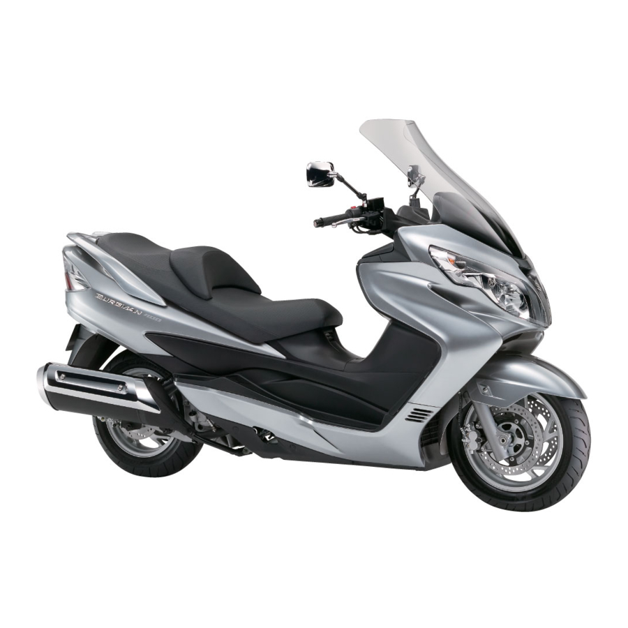
SUZUKI Burgman AN400 Maxi Scooter Manuals
Manuals and User Guides for SUZUKI Burgman AN400 Maxi Scooter. We have
3
SUZUKI Burgman AN400 Maxi Scooter manuals available for free PDF download: Service Manual, Supplementary Service Manual
Suzuki Burgman AN400 Service Manual (475 pages)
Brand:
Suzuki
| Category:
Scooter
| Size: 37 MB
Table of Contents
Section 1 Engine
59
General Information
13
Maintenance and Lubrication
28
Scheduled Maintenance
28
Lubrication Points
29
Brake Hose Replacement
41
Table of Contents
59
Engine General Information and Diagnosis
64
Injection Timing Description
64
Self-Diagnosis Function
65
Schematic and Routing Diagram
67
FI System Wiring Diagram
67
Terminal Alignment of ECM Coupler (Harness Side)
68
Component Location
69
FI System Parts Location
69
Diagnostic Information and Procedures
70
Engine Symptom Diagnosis
70
DTC Table
74
Fail-Safe Function Table
74
FI System Troubleshooting
75
Self-Diagnostic Procedures
76
Self-Diagnosis Reset Procedures
77
Use of SDS Diagnostic Procedures
77
Use of SDS Diagnosis Reset Procedures
78
Show Data When Trouble (Displaying Data at the Time of DTC)
79
Malfunction
83
DTC "C13" (P0105-H/L): IAP Sensor Circuit Malfunction
88
DTC "C14" (P0120/H/L): TP Sensor Circuit Malfunction
93
DTC "C15" (P0115-H/L): ECT Sensor Circuit Malfunction
96
DTC "C16" (P0500): Speed Sensor
99
DTC "C21" (P0110-H/L): IAT Sensor Circuit Malfunction
102
DTC "C23" (P1651-H/L): to Sensor Circuit Malfunction
105
DTC "C24" (P0351): Ignition System Malfunction
108
DTC "C28" (P1655): Secondary Throttle Valve Actuator (STVA) Malfunction
108
DTC "C29" (P1654-H/L): Secondary Throttle Position Sensor (STPS)
112
DTC "C32" (P0201): Fuel Injector Circuit Malfunction
115
DTC "C40" (P0505, P0506 or P0507): ISC Valve Circuit Malfunction
118
DTC "C41" (P0230-H/L): FP Relay Circuit Malfunction
124
DTC "42" (P1650): IG Switch Circuit Malfunction
126
DTC "C44" (P0130, P0135): HO2 Sensor (HO2S) Circuit Malfunction
127
Specifications
130
Service Data
130
Special Tools and Equipment
131
Special Tool
131
Emission Control Devices
132
Precautions
132
Precautions for Emission Control Devices
132
General Description
132
Fuel Injection System Description
132
Crankcase Emission Control System Description
133
Exhaust Emission Control System Description
134
Noise Emission Control System Description
134
Repair Instructions
135
Heated Oxygen Sensor (HO2S) Removal and Installation
135
Heated Oxygen Sensor (HO2S) Inspection
135
PCV Hose Inspection
136
PCV Hose Removal and Installation
136
Specifications
137
Service Data
137
Tightening Torque Specifications
137
ECM Removal and Installation
138
CKP Sensor Inspection
138
CKP Sensor Removal and Installation
138
IAP Sensor Inspection
139
IAP Sensor Removal and Installation
139
TP Sensor Inspection
139
TP Sensor Adjustment
139
TP Sensor Removal and Installation
140
ECT Sensor Inspection
140
ECT Sensor Removal and Installation
140
Speed Sensor Inspection
140
Speed Sensor Removal and Installation
141
IAT Sensor Inspection
141
IAT Sensor Removal and Installation
141
TO Sensor Inspection
141
TO Sensor Removal and Installation
142
STP Sensor Inspection
142
STP Sensor Adjustment
142
STP Sensor Removal and Installation
143
ISC Valve Inspection
143
ISC Valve Removal and Installation
143
Specifications
144
Service Data
144
Tightening Torque Specifications
144
Special Tools and Equipment
144
Special Tool
144
1C-7 Engine Electrical Devices
144
HO2 Sensor Inspection
144
HO2 Sensor Removal and Installation
144
Engine Mechanical
145
Precautions
145
Precautions for Engine Mechanical
145
Schematic and Routing Diagram
145
Camshaft and Sprocket Assembly Diagram
145
Throttle Cable Routing Diagram
146
Diagnostic Information and Procedures
147
Compression Pressure Check
147
Repair Instructions
148
Engine Components Removable with the Engine in Place
148
Engine Assembly Removal and Installation
150
Crankcase Bracket Removal and Installation
153
Crankcase Bracket Inspection
153
Air Cleaner Box Removal and Installation
153
Air Cleaner Element Inspection
154
Air Cleaner Drain Plug Inspection
154
Throttle Cable Removal and Installation
154
Throttle Cable Adjustment
154
Throttle Body Components
155
Throttle Body Construction
156
Throttle Body Removal and Installation
157
Throttle Body Disassembly and Assembly
157
Throttle Body Inspection and Cleaning
159
Engine Top Side Disassembly
160
Engine Top Side Assembly
162
Camshaft Inspection
166
Cam Chain Tension Adjuster Inspection
168
Cam Chain Guide Inspection
169
Cylinder Head Disassembly and Reassembly
169
Cylinder Head Related Parts Inspection
173
Valve Guide Replacement
176
Valve Seat Repair
177
Cylinder Disassembly and Assembly
177
Cylinder Inspection
178
Piston Ring Removal and Installation
178
Piston and Related Parts Inspection
179
Engine Bottom Side Disassembly
181
Engine Bottom Side Assembly
188
Cam Chain Tensioner Inspection
195
Conrod and Crankshaft Inspection
195
Width between Crankshaft Webs
196
Bearing Inspection
196
Bearing Removal and Installation
196
Rear Suspension Mounting Bushing Removal and Installation
198
Specifications
199
Service Data
199
Tightening Torque Specifications
201
Special Tools and Equipment
202
Recommended Service Material
202
Special Tool
202
Engine Lubrication System
205
Precautions
205
Precautions for Engine Oil
205
Schematic and Routing Diagram
205
Engine Lubrication System Chart Diagram
205
Engine Lubrication Circuit Diagram
206
Diagnostic Information and Procedures
207
Engine Lubrication Symptom Diagnosis
207
Oil Pressure Check
207
Repair Instructions
208
Engine Oil and Filter Replacement
208
Oil Sump Filter Removal and Installation
208
Oil Sump Filter Cleaning
208
Oil Pump Removal and Installation
209
Oil Pump Inspection
209
Piston Cooling Nozzle Removal and Installation
209
Piston Cooling Nozzle Inspection
210
Specifications
210
Service Data
210
Tightening Torque Specifications
210
Special Tools and Equipment
211
Special Tool
211
Engine Cooling System
212
Precautions
212
Engine Cooling System Warning
212
General Description
212
Cooling System Description
212
Engine Coolant Description
212
Cooling Fan Thermo-Switch Description
213
Engine Coolant Temperature Sensor Description
214
Schematic and Routing Diagram
215
Cooling Circuit Diagram
215
Radiator Hose Routing Diagram
216
Component Location
216
Engine Cooling System Components Location
216
Diagnostic Information and Procedures
217
Engine Cooling Symptom Diagnosis
217
Repair Instructions
217
Cooling Circuit Inspection
217
Radiator Cap Inspection
218
Radiator Removal and Installation
218
Radiator Cleaning
219
Radiator Hose Inspection
219
Radiator Hose Removal and Installation
220
Radiator Reservoir Tank Removal and Installation
220
Cooling Fan Inspection
220
Cooling Fan Removal and Installation
221
Cooling Fan Thermo-Switch Removal and Installation
221
Cooling Fan Thermo-Switch Inspection
222
ECT Sensor Removal and Installation
222
ECT Sensor Inspection
222
Thermostat Removal and Installation
222
Thermostat Inspection
223
Water Pump Components
224
Water Pump Construction
225
Water Pump Removal and Installation
225
Water Pump Disassembly and Assembly
226
Water Pump Related Parts Inspection
228
Specifications
229
Service Data
229
Tightening Torque Specifications
229
Special Tools and Equipment
230
Recommended Service Material
230
Special Tool
230
Fuel System
231
Precautions
231
Precautions for Fuel System
231
Schematic and Routing Diagram
232
Fuel Tank Hose Construction
232
Diagnostic Information and Procedures
233
Fuel System Diagnosis
233
Repair Instructions
235
Fuel System Components
235
Fuel Tank Heat Shield Construction
236
Fuel Cut Valve Removal and Installation
236
Fuel Tank Removal and Installation
237
Fuel Pump Assembly Removal and Installation
238
Fuel Drain Tray and FTPC Valve Removal and Installation
239
Fuel Cut Valve Inspection
240
FTPC Valve Inspection
240
Fuel Pump Disassembly and Assembly
240
Fuel Pressure Inspection
242
Fuel Pump Relay Inspection
243
Fuel Mesh Filter Inspection
243
Fuel Level Gauge Inspection
243
Fuel Pump Inspection
244
Fuel Injector Inspection
244
Fuel Injector Removal and Installation
244
Specifications
245
Service Data
245
Tightening Torque Specifications
245
Special Tools and Equipment
246
Special Tool
246
Ignition System
247
General Description
247
Immobilizer Description (for
247
Schematic and Routing Diagram
248
Ignition System Diagram
248
Diagnostic Information and Procedures
249
Ignition System Symptom Diagnosis
249
No Spark or Poor Spark
250
Repair Instructions
251
Spark Plug Removal and Installation
251
Spark Plug Inspection and Cleaning
251
Ignition Coil Inspection
251
Ignition Coil Assembly Removal and Installation
252
Spark Plug Removal and Installation
252
Spark Plug Inspection
252
CKP Sensor Inspection
252
CKP Sensor Removal and Installation
254
Engine Stop Switch Inspection
254
Ignition Switch Inspection
254
Ignition Switch Removal and Installation
254
Specifications
255
Service Data
255
Special Tools and Equipment
255
Special Tool
255
Starting System
256
Schematic and Routing Diagram
256
Starting System Diagram
256
Component Location
256
Starting System Components Location
256
Diagnostic Information and Procedures
257
Starter Motor will Not Run
257
Repair Instructions
258
Starter Motor Components
258
Starter Motor Removal and Installation
258
Starter Motor Disassembly and Assembly
259
Starter Motor Inspection
260
Starter Relay Removal and Installation
261
Starter Relay Inspection
261
Turn Signal / Side-Stand Relay Removal and Installation
262
Side-Stand / Ignition Interlock System Parts Inspection
262
Starter Clutch Component
264
Starter Clutch Removal and Installation
264
Starter Clutch Inspection
265
Starter Clutch Disassembly and Assembly
265
Starter Button Inspection
266
Specifications
266
Service Data
266
Tightening Torque Specifications
266
Special Tools and Equipment
267
Recommended Service Material
267
Special Tool
267
Charging System
268
Schematic and Routing Diagram
268
Charging System Diagram
268
Component Location
268
Charging System Components Location
268
Diagnostic Information and Procedures
269
Charging System Symptom Diagnosis
269
Battery Runs down Quickly
270
Repair Instructions
271
Battery Current Leakage Inspection
271
Regulated Voltage Inspection
271
Generator Coil Resistance Inspection
272
Generator No-Load Performance Inspection
272
Regulator/Rectifier Inspection
272
Generator Removal and Installation
273
Battery Components
275
Battery Initial Charging
275
Battery Visual Inspection
276
Battery Recharging
277
Battery Removal and Installation
277
Specifications
278
Service Data
278
Tightening Torque Specifications
278
Special Tools and Equipment
278
Special Tool
278
Exhaust System
279
Precautions
279
Precautions for Exhaust System
279
Repair Instructions
279
Exhaust System Components
279
Exhaust Pipe / Muffler Removal and Installation
280
Exhaust System Inspection
282
HO2 Sensor Inspection
282
Specifications
283
Tightening Torque Specifications
283
Special Tools and Equipment
283
Recommended Service Material
283
Section 2 Suspension
285
Precautions
286
Precautions for Suspension
286
Suspension General Diagnosis
287
Diagnostic Information and Procedures
287
Suspension and Wheel Symptom Diagnosis
287
Repair Instructions
288
Front Fork Components
288
Front Fork Removal and Installation
289
Front Fork Disassembly and Assembly
290
Front Fork Inspection
295
Front Fork Parts Inspection
295
Front Suspension
288
Specifications
296
Service Data
296
Tightening Torque Specifications
296
Special Tools and Equipment
297
Recommended Service Material
297
Special Tool
297
Rear Suspension
298
Repair Instructions
298
Rear Suspension Components
298
Rear Suspension Assembly Construction
299
Rear Swingarm Components
300
Rear Shock Absorber and Rear Shock Absorber Assembly Removal and Installation
301
Rear Suspension Inspection
302
Rear Shock Absorber Inspection
302
Rear Shock Absorber Gas Pressure Release
302
Rear Suspension Adjustment
303
Rear Swingarm Removal and Installation
303
Rear Swingarm Related Parts Inspection
304
Rear Swingarm Dust Seal / Bearing Removal and Installation
305
Cushion Lever and Cushion Rod Inspection
306
Cushion Lever Bearing Removal and Installation
307
Crankcase Bracket Construction
308
Crankcase Bracket Removal and Installation
309
Crankcase Bracket Related Parts Inspection
309
Crankcase Bracket Bearing Removal and Installation
310
Specifications
311
Service Data
311
Tightening Torque Specifications
311
Special Tools and Equipment
312
Recommended Service Material
312
Special Tool
312
Precautions
313
Precautions for Wheel and Tire
313
Wheels and Tires
313
Repair Instructions
314
Front Wheel Components
314
Front Wheel Assembly Construction
315
Front Wheel Assembly Removal and Installation
316
Front Wheel Related Parts Inspection
317
Front Wheel Dust Seal / Bearing Removal and Installation
318
Rear Wheel Components
320
Rear Wheel Assembly Removal and Installation
321
Rear Wheel Related Parts Inspection
323
Tire Removal and Installation
323
Wheel/Tire/Air Valve Inspection and Cleaning
325
Air Valve Removal and Installation
326
Wheel Balance Check and Adjustment
326
Specifications
327
Service Data
327
Tightening Torque Specifications
327
Special Tools and Equipment
328
Recommended Service Material
328
Special Tool
328
Section 3 Driveline / Axle
329
Precautions
330
Precautions for Driveline/Axle
330
Drive Chain / Drive Train / Drive Shaft
331
Diagnostic Information and Procedures
331
Drive Chain and Sprocket Symptom Diagnosis
331
Repair Instructions
332
Final Gear Components
332
Final Gear Assembly Removal and Installation
333
Final Gear Disassembly and Assembly
334
Final Drive Gear Bearing Inspection
338
Specifications
339
Tightening Torque Specifications
339
Special Tools and Equipment
339
Recommended Service Material
339
Special Tool
339
Section 4 Brake
341
Precautions
343
Precautions for Brake System
343
Brake Fluid Information
343
Brake Control System and Diagnosis
344
Schematic and Routing Diagram
344
Front Brake Hose Routing Diagram
344
Rear Brake Hose Routing Diagram
345
Diagnostic Information and Procedures
346
Brake Symptom Diagnosis
346
Repair Instructions
346
Brake Light Switch Inspection
346
Brake Fluid Level Check
347
Brake Hose Inspection
347
Air Bleeding from Brake Fluid Circuit
347
Brake Fluid Replacement
348
Front Brake Hose Removal and Installation
349
Rear Brake Hose Removal and Installation
349
Front Brake Master Cylinder Components
350
Front Brake Master Cylinder Assembly Removal and Installation
351
Front Master Cylinder / Brake Lever Disassembly and Assembly
352
Front Master Cylinder Parts Inspection
353
Rear Brake Master Cylinder Components
354
Rear Brake Master Cylinder Assembly Removal and Installation
355
Rear Master Cylinder / Brake Lever Disassembly and Assembly
355
Rear Master Cylinder Parts Inspection
355
Service Data
356
Special Tools and Equipment
357
Recommended Service Material
357
Special Tool
357
Front Brakes
358
Repair Instructions
358
Front Brake Components
358
Front Brake Pad Inspection
359
Front Brake Pad Replacement
359
Front Brake Caliper Removal and Installation
360
Front Brake Caliper Disassembly and Assembly
361
Front Brake Caliper Parts Inspection
362
Front Brake Disc Removal and Installation
363
Front Brake Disc Inspection
363
Specifications
364
Service Data
364
Tightening Torque Specifications
364
Special Tools and Equipment
365
Recommended Service Material
365
Special Tool
365
Repair Instructions
366
Rear Brake Components
366
Rear Brake Pad Inspection
367
Rear Brake Pad Replacement
367
Rear Brake Caliper Removal and Installation
368
Rear Brake Caliper Disassembly and Assembly
369
Brake Caliper Piston Disassembly and Assembly
372
Rear Brake Caliper Parts Inspection
373
Rear Brake Disc Removal and Installation
374
Rear Brake Disc Inspection
374
Rear Brakes
366
Special Tools and Equipment
375
Recommended Service Material
375
Special Tool
375
Specifications
375
Tightening Torque Specifications
375
Parking Brake
376
General Description
376
Parking Brake System (Brake-Lock System) Description
376
Schematic and Routing Diagram
381
Parking Brake Cable (Brake-Lock Cable) Routing Diagram
381
Repair Instructions
382
Parking Brake System (Brake-Lock System) Inspection
382
Parking Brake System (Brake-Lock System) Removal and Installation
382
Section 5 Tranmission / Transaxle
385
Precautions
386
Precautions for Transmission/Transaxle
386
Automatic Transmission
387
Schematic and Routing Diagram
387
Drive Train System
387
Diagnostic Information and Procedures
388
Automatic Transmission Symptom Diagnosis
388
Repair Instructions
388
Outer Clutch Cover Cushion Construction
388
Clutch in / Stall Speed Inspection
389
V-Belt Type Continuously Variable Automatic Transmission Removal and Installation
389
Drive V-Belt Inspection
392
Cooling Fan Filter Inspection
392
Inner Clutch Cover Bearing Inspection
393
Inner Clutch Cover Bering Removal and Installation
393
Movable Drive Face Component
394
Movable Drive Face Disassembly and Assembly
394
Movable Drive Face Parts Inspection
395
Oil Seal Removal and Installation
396
Clutch Shoe / Movable Driven Face Components
397
Clutch Shoe / Movable Driven Face Disassembly and Assembly
398
Clutch Shoe and Movable Driven Face Parts Inspection
402
Specifications
403
Service Data
403
Tightening Torque Specifications
403
Special Tools and Equipment
404
Recommended Service Material
404
Special Tool
404
Section 6 Steering
405
Precautions
406
Precautions for Steering
406
Steering General Diagnosis
407
Diagnostic Information and Procedures
407
Steering Symptom Diagnosis
407
Steering / Handlebar
408
Repair Instructions
408
Handlebars Components
408
Handlebars Removal and Installation
409
Handlebars Inspection
411
Steering Components
412
Steering Removal and Installation
413
Steering Related Parts Inspection
416
Steering System Inspection
416
Steering Stem Bearing Removal and Installation
416
Steering Tension Adjustment
417
Specifications
418
Tightening Torque Specifications
418
Special Tools and Equipment
419
Recommended Service Material
419
Special Tool
419
Advertisement
Suzuki Burgman AN400 Service Manual (384 pages)
Brand:
Suzuki
| Category:
Scooter
| Size: 31 MB
Table of Contents
General Information 1
7
General Information
2
Servicing Information
2
Table of Contents
7
Periodic Maintenance
2
Electrical System
2
Warning/Caution/Note
8
General Precautions
8
Suzuki An400 ( 03-Model)
10
Serial Number Location
10
Fuel, Oil and Engine Coolant Recommendation
10
Fuel (for Usa and Canada)
10
Fuel (for Other Countries)
10
Engine Oil and Transmission Oil (for Usa)
11
Engine Oil and Transmission Oil (for Other Countries)
11
Final Gear Oil
11
Brake Fluid
11
Front Fork Oil
11
Engine Coolant
11
Water for Mixing
11
Anti-Freeze/Engine Coolant
11
Liquid Amount of Water/Engine Coolant
12
Break-In Procedures
13
Information Labels
14
Specifications
15
Dimensions and Dry Mass
15
Engine
15
Drive Train
15
Chassis
15
Electrical
16
Capacities
16
Country and Area Codes
17
Periodic Maintenance Schedule
19
Periodic Maintenance Chart
19
Lubrication Points
20
Maintenance and Tune-Up Procedures
21
Air Cleaner
21
Exhaust Pipe Bolt and Muffler Bolt
22
Valve Clearance
22
Spark Plug
24
Fuel Line
25
Engine Oil and Oil Filter
25
Final Gear Oil
27
Idle Speed
28
Throttle Cable Play
29
Cooling Fan Filter
30
Cooling System
30
Drive V-Belt Inspection
32
Pair(Air Supply)System
32
Brake System
33
Steering
37
Front Fork
38
Rear Suspension
38
Tire
39
Tire Tread Depth
39
Chassis Bolt and Nut
40
Compression Pressure Check
42
Compression Test Procedure
42
Oil Pressure Check
43
Oil Pressure Test Procedure
43
Automatic Clutch Inspection
44
Initial Engagement Inspection
44
Clutch "Lock-Up" Inspection
44
Brake-Lock
45
Inspection
45
Adjustment
45
Engine
47
Engine Components Removable with the Engine in Place
49
Engine Removal and Remounting
50
Engine Removal
50
Engine Remounting
54
Engine Disassembly
56
Engine Component Inspection and Service
69
Cylinder Head Cover
69
Camshaft Housing
70
Cylinder Head
71
Cylinder Head Distortion
72
Camshaft
81
Cam Chain Tension Adjuster
82
Cylinder
84
Piston
84
Conrod and Crankshaft
86
Movable Drive Face Assembly
88
Clutch Shoe/Movable Driven Face
90
Transmission Cover
96
Idle Gear
98
Final Driven Gear
99
Scissors Gear
99
Clutch Inner Cover
100
Starter Clutch
102
Generator
103
Oil Sump Filter
105
Oil Pump
105
Crankcase
105
Engine Reassembly
111
Crankshaft
111
Balancer Shaft
111
Crankcase
111
Balancer Gear
113
Starter Idle Gear
114
Cam Chain
115
Oil Pump
115
Starter Driven Gear
116
Generator Rotor
116
Oil Sump Filter
116
Idle Shaft
117
Rear Axle Shaft
117
Transmission/Transmission Cover
118
Clutch Shoe/Movable Driven Face Assembly
118
Movable Drive Face Assembly
120
Clutch Inner Cover
120
Generator Cover
121
Water Pump
121
Oil Filter
122
Piston Ring
122
Piston
123
Cylinder
124
Cam Chain Guide
124
Cylinder Head
124
Camshaft
125
Cam Chain Tension Adjuster
127
Cylinder Head Cover
127
Starter Motor
128
Fi System
129
Precautions in Servicing
130
Eletrical Parts
130
Fuse
131
Ecm/Various Sensors
131
Electrical Circuit Inspection Procedure
133
Using Testers
136
Fi System Technical Features
137
Injection Time (Injection Volume)
137
Compensation of Injection Time (Volume)
138
Injection Stop Control
138
Fi System Parts Location
139
Fi System Wiring Diagram
141
Self-Diagnosis Function
142
User Mode
142
Dealer Mode
143
Tps Adjustment
144
Fail-Safe Function
145
Fi System Troubleshooting
146
Customer Complaint Analysis
146
Self-Diagnostic Procedures
148
Self-Diagnosis Reset Procedure
148
Malfunction Code and Defective Condition
149
C12" Ckp Sensor Circuit Malfunction
151
C13" Iap Sensor Circuit Malfunction
153
C14" Tp Sensor Circuit Malfunction
156
C15" Ect Sensor Circuit Malfunction
159
C21" Iat Sensor Circuit Malfunction
161
C23" to Sensor Circuit Malfunction
163
C24" Igintion System Malfunction
164
C32" Fuel Injector Circuit Malfunction
165
C40" Iac Valve Circuit Malfunction
167
C41" Fp Relay Circuit Malfunction
169
C42" Ig Switch Circuit Malfunction
169
C44" Ho2 Sensor (Ho2S) Circuit Malfunction (E-02, 19, 54)
170
Sensors
172
Fuel System and Throttle Body
174
Fuel System
175
Removal and Disassembly
176
Inspection
178
Reassembly and Installation
179
Fuel Pressure Inspection
180
Fuel Pump Inspection
181
Fuel Pump Relay Inspection
182
Fuel Pump and Fuel Level Gauge Disassembly
182
Fuel Mesh Filter Inspection and Cleaning
183
Fuel Level Gauge Inspection
184
Fuel Pump and Fuel Level Gauge Reassembly
185
Throttle Body
186
Removal
187
Disassembly
189
Cleaning and Inspection
191
Reassembly
192
Installation
193
Throttle Cable Adjustment
193
Tp Sensor Adjustment
194
Fuel Injector Removal
194
Fuel Injector Inspection
194
Fuel Injector Installation
194
Cooling and Lubrication System
195
Cooling System
196
Description
196
Cooling Circuit
196
Engine Coolant
197
Draining Engine Coolant
197
Removal and Disassembly
198
Radiator
198
Inspection
199
Radiator
199
Water Hose
199
Cooling Fan
199
Reassembly and Remounting
200
Cooling Fan Thermo-Switch
201
Removal
202
Inspection
202
Inistallation
202
Engine Coolant Temperature Sensor
203
Removal
203
Inspection
203
Installation
203
Thermostat
204
Removal
204
Inspection
204
Installtation
205
Water Pump
206
Removal and Disassembly
206
Inspection
207
Reassembly and Remounting
207
Lubrication System
210
Oil Pressure
210
Oil Filter
210
Oil Sump Filter
210
Oil Pump
210
Engine Lubrication System Chart
210
Engine Lubrication System
211
Chassis
212
Exterior Parts
214
Construction
214
Removal
220
Fastener Removal and Reinstallation
221
Installation
230
Front Wheel
231
Removal and Disassembly
231
Inspection
232
Reassembly and Remounting
233
Front Brake
236
Caliper Removal and Disassembly
237
Caliper Inspection
238
Caliper Reassembly and Remounting
238
Brake Disc Inspection
240
Master Cylinder Removal and Disassembly
240
Master Cylinder Inspection
241
Master Cylinder Reassembly and Remounting
242
Handlebars
244
Removal
244
Reassembly
245
Front Fork
246
Removal and Disassembly
246
Front Fork Spring Inspection
249
Inner Tube and Outer Tube Inspection
249
Cylinder Inspection
249
Reassembly and Remounting
250
Steering
254
Removal and Disassembly
254
Inspection
256
Reassembly and Remounting
256
Rear Wheel
259
Removal
259
Inspection
260
Remounting
260
Rear Brake
262
Brake Pad Replacement
263
Caliper Removal and Disassembly
264
Caliper Inspection
266
Caliper Reassembly and Remounting
266
Brake Disc Removal
269
Brake Disc Inspection
270
Brake Disc Reassembly
270
Master Cylinder Removal and Disassembly
271
Master Cylinder Inspection
272
Master Cylinder Reassembly and Remounting
272
Delay Valve Removal
273
Delay Valve Remounting
273
Brake-Lock Cable Replacement
273
Brake System
276
Rear Suspension
280
Removal and Disassembly
280
Inspection
281
Rear Shock Absorber Disposal
282
Reassembly and Remounting
284
Crankcase Bracket
286
Removal and Disassembly
286
Inspection
286
Bearing Replacement
287
Reassembly and Remounting
288
Tire and Wheel
289
Tire Removal
289
Inspection
289
Valve Inspection
290
Tire Installation
291
Balancer Weight Installation
292
Electrical System
293
Cautions in Servicing
295
Connectors
295
Couplers
295
Clamps
295
Fuse
295
Semi-Conductor Equipped Parts
296
Battery
296
Connecting the Battery
296
Wiring Procedure
296
Using the Multi Circuit Tester
297
Location of Electrical Components
298
Battery
300
Charging System
300
Trouble Shooting
300
Charging System Inspection
302
Generator
300
Main Fuse
300
Starter System
305
Trouble Shooting
305
Starter Motor Removal and Disassembly
306
Starter Motor Inspection
307
Starter Motor Reassembly and Installation
308
Starter Relay Inspection
310
Side-Stand/Ignition Interlock System Parts Inspection
310
Ignition System
313
Troubleshooting
313
Ignition System Inspection
315
Combination Meter
318
Removal and Disassembly
318
Inspection
319
Fuel Level Meter Inspection
320
Headlight
321
Lamp
321
Front Turn Signal Light
322
Brake Light/Taillight
323
Rear Turn Signal Light/Brake Light/Taillight/License Light
323
Switches
324
Ignition Switch Removal and Remounting
324
Inspection
325
Battery
326
Specifications
326
Initial Charging
326
Servicing
327
Recharging Operation
328
Battery Removal
328
Suzuki Burgman AN400 Supplementary Service Manual (143 pages)
Brand:
Suzuki
| Category:
Scooter
| Size: 6 MB
Table of Contents
General Information
7
Service Data
13
Fuel System
24
Rear Suspension
29
Wheels and Tires
30
Table of Contents
38
Repair Instructions
41
Specifications
42
Tightening Torque Specifications
42
Abs
43
Precautions
43
Precautions for ABS (AN400A/ZAK9)
43
ABS Information (AN400A/ZAK9)
43
General Description
43
Wheel Speed Sensor Description (AN400A/ZAK9)
43
ABS Control Unit Description (AN400A/ZAK9)
44
Hydraulic Unit (HU) Description (AN400A/ZAK9)
46
Self-Diagnosis Function and ABS Indicator Light Description (AN400A/ZAK9)
47
Fail-Safe Function Description (AN400A/ZAK9)
48
Schematic and Routing Diagram
49
ABS Wiring Diagram (AN400A/ZAK9)
49
ABS Unit Diagram (AN400A/ZAK9)
50
Front Wheel Speed Sensor Routing Diagram (AN400A/ZAK9)
51
Rear Wheel Speed Sensor Routing Diagram (AN400A/ZAK9)
52
Component Location
53
ABS Components Location (AN400A/ZAK9)
53
Diagnostic Information and Procedures
54
ABS Troubleshooting (AN400A/ZAK9)
54
Pre-Diagnosis Inspection (AN400A/ZAK9)
56
ABS Indicator Light Inspection (AN400A/ZAK9)
58
DTC (Diagnostic Trouble Code) Output
64
(An400A/Zak9)
67
DTC (Diagnostic Trouble Code) Deleting (AN400A/ZAK9)
67
SDS Check (AN400A/ZAK9)
69
Active Control Inspection (AN400A/ZAK9)
70
DTC Table (AN400A/ZAK9)
73
DTC "13" (C1613): Wheel Speed Sensor Rotor Malfunction (F) (AN400A/ZAK9)
74
DTC "14" (C1614): Wheel Speed Sensor Rotor Malfunction (R) (AN400A/ZAK9)
76
DTC "22" (C1622): ABS Actuator Circuit Malfunction (F) (AN400A/ZAK9)
78
DTC "23" (C1623): ABS Actuator Circuit Malfunction (R) (AN400A/ZAK9)
80
DTC "25" (C1625): Wheel Speed Sensor Related Malfunction (AN400A/ZAK9)
82
DTC "35" (C1635): ABS Motor Malfunction (AN400A/ZAK9)
84
DTC "41" (C1641): Wheel Speed Sensor Signal Malfunction (F) (AN400A/ZAK9)
86
DTC "42" (C1642): Wheel Speed Sensor Circuit Open (F) (AN400A/ZAK9)
88
DTC "43" (C1643): Wheel Speed Sensor Circuit Short (F) (AN400A/ZAK9)
94
DTC "44" (C1644): Wheel Speed Sensor Signal Malfunction (R) (AN400A/ZAK9)
96
DTC "45" (C1645): Wheel Speed Sensor Circuit Open (R) (AN400A/ZAK9)
98
DTC "46" (C1646): Wheel Speed Sensor Circuit Short (R) (AN400A/ZAK9)
103
DTC "47" (C1647): Supply Voltage (Increased) (AN400A/ZAK9)
105
DTC "48" (C1648): Supply Voltage (Decreased) (AN400A/ZAK9)
107
DTC "55" (C1655): ABS Control Unit Malfunction (AN400A/ZAK9)
109
DTC "61" (C1661): ABS Solenoid Malfunction (AN400A/ZAK9)
111
Repair Instructions
113
ABS Control Unit Coupler Disconnect and Connect (AN400A/ZAK9)
113
Front Wheel Speed Sensor Removal and Installation (AN400A/ZAK9)
113
Rear Wheel Speed Sensor Removal and Installation (AN400A/ZAK9)
114
Front Wheel Speed Sensor Rotor Removal and Installation (AN400A/ZAK9)
115
Rear Wheel Speed Sensor Rotor Removal and Installation (AN400A/ZAK9)
115
Wheel Speed Sensor and Sensor Rotor Inspection (AN400A/ZAK9)
116
ABS Control Unit/Hu Removal and Installation (AN400A/ZAK9)
117
Advertisement
Advertisement
Related Products
Suzuki AN400ZA
Suzuki AN400A
Suzuki AN650/A
Suzuki AP 50
Suzuki AN125HK
Suzuki AY50
Suzuki AN400 2003
Suzuki Burgman UH125
Suzuki Burgman Series
Suzuki AN650
SUZUKI Categories
Motorcycle
Automobile
Motorcycle Accessories
Outboard Motor
Offroad Vehicle
More SUZUKI Manuals
Login
Sign In
OR
Sign in with Facebook
Sign in with Google
Upload manual
Upload from disk
Upload from URL