
Related Manuals for Suzuki AN400


Summary of Contents for Suzuki AN400
- Page 1 AN400/A/ZA SUPPLEMENTARY SERVICE MANUAL USE THIS MANUAL WITH: AN400 SERVICE MANUAL (99500-34101-01E) 9 9 5 0 1 - 3 4 1 7 0 - 0 1 E...
- Page 2 * This manual is written for persons who have enough knowledge, skills and tools, including special tools, for servicing SUZUKI motorcycles. If you do not have the proper knowledge and tools, ask your authorized SUZUKI motorcycle dealer to help you.
- Page 3 TABLE OF CONTENTS NOTE For the screen toned sections with asterisk (*) in the “TABLE OF CONTENTS” below, refer to the same sections of the service manual mentioned in the “FOREWORD” of this manual. Precautions............... 00-i Precautions ............00-1 General Information ........... 0-i General Information ..........
- Page 5 Table of Contents 00- i Section 00 Precautions CONTENTS NOTE For the items with asterisk (*) in the “CONTENTS” below, refer to the same section of the service manual mentioned in the “FOREWORD” of this manual. Precautions ..........00-1 General Precautions ..........00-* Precautions for Electrical Circuit Service .....00-* Precautions............
- Page 6 00-1 Precautions: Precautions Precautions Precautions Precautions for ABS (AN400A/ZAK9) • Never subject the ABS control unit/HU to strong B905H10000004 impacts or allow them to be dropped. ABS Wiring • The ABS parts are connected to various lead wires. The coupler and lead wire connections, as well as the lead wire and wire harness routings must be done correctly.
-
Page 7: General Information
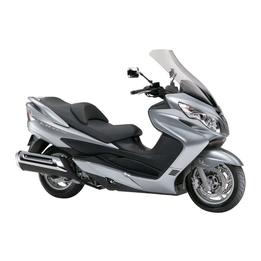
Abbreviations (AN400A/ZAK9) ......0A-1 Brake Hose Replacement ........0B-* Vehicle Side View (AN400/A/ZAK9)....0A-1 Air Bleeding from Brake Fluid Circuit ....0B-* Country and Area Codes (AN400/A/ZAK9)..0A-2 Brake Fluid Replacement........0B-* Component Location ........... 0A-* Tire Inspection............. 0B-* Electrical Components Location ......0A-* Steering System Inspection ........ - Page 8 Abbreviations (AN400A/ZAK9) B905H10101012 NOTE Please refer to the AN400K8 service manual for other abbreviations which are not given in this manual. ABS: Anti-lock Brake System Vehicle Side View (AN400/A/ZAK9) SUZUKI AN400A (2009-model) B905H10101013 NOTE Right Side Difference between illustration and actual motorcycles may exist depending on the markets.
- Page 9 General Information: 0A-2 SUZUKI AN400ZA (2009-model) Left Side Right Side I905H1010006-02 I905H1010005-01 Country and Area Codes (AN400/A/ZAK9) B905H10101014 The following codes stand for the applicable country(-ies) and area(-s). Model Code Country or Area Effective Frame No. E-02 U.K. JS1CG111200100924 –...
- Page 10 0A-3 General Information: Specifications Specifications (AN400K9) B905H10107005 NOTE • These specifications are subject to change without notice. • Any differences between the AN400K8 (’08-model) and AN400K9 (’09-model) in specifications are indicated an asterisk mark (*). Dimensions and Curb Mass Item Specification Remark Overall length...
- Page 11 General Information: 0A-4 Electrical Item Specification Remark lgnition type Electronic ignition (Transistorized) lgnition timing 7° B. T. D. C at 1 450 r/min Spark plug NGK: CR7E or DENSO: U22ESR-N Battery 12 V 32.4 kC (9 Ah)/10 HR Generator Three-phase A.C. generator Main fuse 30 A 10/10/15/10/15/10 A...
- Page 12 0A-5 General Information: Special Tools and Equipment Special Tool B905H10108002 09900–20803 09900–20806 09900–25008 09900–25009 09904–41010 Thickness gauge Thickness gauge Multi circuit tester set Needle-point probe SUZUKI Diagnostic system set 09930–82710 99565–01010–020 Mode select switch CD-ROM Ver.20...
-
Page 13: Service Data
Service Data: 0C-1 Service Data General Information Specifications Service Data (AN400K9) B905H10307004 NOTE Any differences between the AN400K8 (’08-model) and AN400K9 (’09-model) is service data are indicated an asterisk mark (*). Clutch Unit: mm (in) Item Specification Limit Clutch wheel I.D. 160 –... - Page 14 0C-2 Service Data: Service Data (AN400A/ZAK9) B905H10307005 NOTE Any differences between the AN400K9 (’09-model) and AN400A/ZAK9 (’09-model) in service data are indicated an asterisk mark (*). Electrical Unit: mm (in) Item Standard / Specification Note 10 A E-02, 19, 24, 54 15 A E-03, 28, 33 Headlight...
- Page 15 Service Data: 0C-3 Brake + Wheel Unit: mm (in) Item Standard Limit 4.5 ± 0.2 (0.18 ± 0.008) Front 4.0 (0.16) Brake disc thickness 5.0 ± 0.2 (0.20 ± 0.008) Rear 4.5 (0.18) Brake disc runout — 0.30 (0.01) Front * 14.000 –...
- Page 16 0C-4 Service Data:...
- Page 17 Table of Contents 1- i Section 1 Engine CONTENTS NOTE For the items with asterisk (*) in the “CONTENTS” below, refer to the same section of the service manual mentioned in the “FOREWORD” of this manual. Precautions ..........1-* DTC “C28” (P1655): Secondary Throttle Valve Actuator (STVA) Malfunction....
- Page 18 ISC Valve Inspection........... 1C-* Rear Suspension Mounting Bushing Removal ISC Valve Removal and Installation....1C-* and Installation ..........1D-* ISC Valve Pre-set (AN400/ZK7)......1C-* Engine Bottom Side Assembly (AN400/A/ ISC Valve Preset and Opening Initialization ZAK9) ..............1D-2 (AN400/ZK8) ............. 1C-* Specifications ............1D-3...
- Page 19 Radiator Hose Routing Diagram ......1F-* Fuel Injector Inspection ........1G-* Component Location ..........1F-* Fuel Injector Removal and Installation ....1G-* Engine Cooling System Components Fuel Pump Components (AN400/A/ZAK9)..1G-1 Location .............1F-* Fuel Pump Disassembly and Assembly Diagnostic Information and Procedures.....1F-* (AN400/A/ZAK9) ..........1G-2 Engine Cooling Symptom Diagnosis....1F-*...
- Page 20 Precautions for Exhaust System ......1K-* Component Location ..........1J-* Repair Instructions ..........1K-* Charging System Components Location....1J-* Exhaust System Construction (AN400/ZK7) ..1K-* Exhaust System Construction (AN400/ZK8) ..1K-* Diagnostic Information and Procedures..... 1J-* Exhaust Pipe / Muffler Removal and Charging System Symptom Diagnosis....
- Page 21 Engine Mechanical: 1D-1 Engine Mechanical Engine Schematic and Routing Diagram Throttle Cable Routing Diagram (AN400/A/ZAK9) B905H11402003 “ a ” “D” Upside Inside “C” “B” “A” Upside Inside I905H1140001-02 1. Clamp 8. Throttle cable No. 2 : Bind the parking brake cable, starter motor lead wire and seat- lock cable with the clamp.
- Page 22 1D-2 Engine Mechanical: Repair Instructions Engine Bottom Side Assembly (AN400/A/ZAK9) • Clean and degrees the crankcase mating surfaces B905H11406036 (both surfaces) with a cleaning solvent. For engine bottom side assembly other than the • Apply bond to the right crankcase and part “a” of the following, refer to “Engine Bottom Side Assembly”...
- Page 23 For the tightening torque of fastener not specified in this section, refer to “Tightening Torque List” in Section 0C in related manual. Special Tools and Equipment Recommended Service Material B905H11408001 Material SUZUKI recommended product or Specification Note Sealant SUZUKI BOND No.1207B or P/No.: 99000–31140 (Page 1D-2)
-
Page 24: Fuel System
1G-1 Fuel System: Fuel System Engine Repair Instructions Fuel Pump Components (AN400/A/ZAK9) B905H11706017 I905H1170003-01 1. Fuel level gauge 5. Fuel pump 9. Fuel pump mounting bolt 2. O-ring 6. Fuel mesh filter : 10 N⋅m (1.0 kgf-m, 7.0 lbf-ft) 3. Fuel pressure regulator assembly 7. - Page 25 Fuel System: 1G-2 Fuel Pump Disassembly and Assembly (AN400/ 3) For the other procedure, refer to “Fuel Pump Disassembly and Assembly” in related manual. A/ZAK9) B905H11706018 Disassembly Assembly 1) Remove the fuel pump assembly. Assemble the fuel pump assembly in the reverse order Refer to “Fuel Pump Assembly Removal and...
- Page 26 1G-3 Fuel System:...
- Page 27 Precautions.............. 2-* Crankcase Bracket Bearing Removal and Precautions for Suspension ........2-* Installation ............2C-* Suspension General Diagnosis....2A-* Rear Swingarm Construction (AN400/A/ ZAK9) ..............2C-1 Diagnostic Information and Procedures.... 2A-* Specifications ............2C-* Suspension and Wheel Symptom Diagnosis ..2A-* Service Data............2C-* Front Suspension ........2B-*...
- Page 28 2-ii Table of Contents Specifications............2D-7 Special Tools and Equipment ......2D-7 Service Data............2D-* Recommended Service Material ......2D-7 Tightening Torque Specifications......2D-7 Special Tool ............2D-7...
-
Page 29: Rear Suspension
Rear Suspension: 2C-1 Rear Suspension Suspension Repair Instructions Rear Swingarm Construction (AN400/A/ZAK9) B905H12306018 I905H1230001-01 1. Rear swingarm 3. Swingarm cushion No. 2 5. Swingarm cushion cover 2. Swingarm cushion No. 3 4. Swingarm cushion No. 1... -
Page 30: Wheels And Tires
2D-1 Wheels and Tires: Wheels and Tires Suspension Repair Instructions Front Wheel Components (AN400A/ZAK9) B905H12406013 I905H1240001-02 1. Front wheel 6. Collar 11. Wheel balancer : 6 N⋅m (0.6 kgf-m, 4.5 lbf-ft) 2. Spacer 7. Brake disk 12. Wheel speed sensor rotor : Apply grease. - Page 31 Wheels and Tires: 2D-2 Front Wheel Assembly Construction (AN400A/ZAK9) B905H12406014 “a ” “ b ” I905H1240010-02 1. Front axle “a”: Clearance : 23 N⋅m (2.3 kfg-m, 16.5 lbf-ft) 2. Front brake caliper mounting bolt “b”: 0.36 – 1.62 mm (0.014 – 0.064 in) : 6 N⋅m (0.6 kfg-m, 4.5 lbf-ft) 3.
- Page 32 2D-3 Wheels and Tires: Front Wheel Assembly Removal and Installation Installation Refer to “Front Wheel Related Parts Inspection” in (AN400A/ZAK9) related manual. B905H12406015 CAUTION Refer to “Wheel Speed Sensor and Sensor Rotor Inspection (AN400A/ZAK9)” in Section 4E (Page 4E-74). • The ABS is made up of many precision Install the front wheel assembly in the reverse order of parts;...
- Page 33 Wheels and Tires: 2D-4 Rear Wheel Components (AN400A/ZAK9) B905H12406016 I905H1240006-01 1. Rear axle 7. Rear axle nut : 23 N⋅m (2.3 kgf-m, 16.5 lbf-ft) 2. Brake disc 8. Tire : 120 N⋅m (12.0 kgf-m, 87.0 lbf-ft) 3. Brake disc bolt 9.
- Page 34 2D-5 Wheels and Tires: Rear Wheel Assembly Construction (AN400A/ZAK9) B905H12406017 “ a ” I905H1240011-04 1. Rear axle nut 5. Rear wheel speed sensor rotor bolt : 6 N⋅m (0.6 kgf-m, 4.5 lbf-ft) 2. Rear brake caliper mounting bolt “a”: 0.16 – 1.62 mm (0.006 – 0.064 in) : Apply grease.
- Page 35 Wheels and Tires: 2D-6 Rear Wheel Assembly Removal and Installation Installation Refer to “Rear Wheel Related Parts Inspection” in (AN400A/ZAK9) related manual. B905H12406018 CAUTION Refer to “Wheel Speed Sensor and Sensor Rotor Inspection (AN400A/ZAK9)” in Section 4E (Page 4E-74). • The ABS is made up of many precision Install the rear wheel assembly in the reverse order of parts;...
- Page 36 2D-7 Wheels and Tires: Specifications Tightening Torque Specifications B905H12407002 NOTE The specified tightening torque is described in the following. “Front Wheel Components (AN400A/ZAK9)” (Page 2D-1) “Front Wheel Assembly Construction (AN400A/ZAK9)” (Page 2D-2) “Rear Wheel Components (AN400A/ZAK9)” (Page 2D-4) “Rear Wheel Assembly Construction (AN400A/ZAK9)” (Page 2D-5) Reference: For the tightening torque of fastener not specified in this section, refer to “Tightening Torque List”...
- Page 37 Table of Contents 4- i Section 4 Brake CONTENTS NOTE For the items with asterisk (*) in the “CONTENTS” below, refer to the same section of the service manual mentioned in the “FOREWORD” of this manual. Precautions ..........4-* Special Tool ............4A-* Precautions..............
-
Page 38: Table Of Contents
4-ii Table of Contents Parking Brake Cable (Brake-lock Cable) DTC “13” (C1613): Wheel Speed Sensor Routing Diagram ..........4D-* Rotor Malfunction (F) (AN400A/ZAK9)....4E-32 DTC “14” (C1614): Wheel Speed Sensor Repair Instructions ..........4D-* Rotor Malfunction (R) (AN400A/ZAK9) ...4E-34 Parking Brake System (Brake-lock System) DTC “22”... - Page 39 Brake Control System and Diagnosis: 4A-1 Brake Control System and Diagnosis Brake Schematic and Routing Diagram Front Brake Hose Routing Diagram (AN400A/ZAK9) B905H14102003 “B” “A” I905H1410001-02 1. ABS control unit/HU 9. Rear brake pipe No. 2 2. Rubber 10. Front brake hose No. 2 3.
- Page 40 4A-2 Brake Control System and Diagnosis: Rear Brake Hose Routing Diagram (AN400A/ZAK9) B905H14102004 “A” “A” “ a ” “C” “ b ” “B” I905H1410003-01 1. Rear brake pipe No. 2 “B”: Fix the brake hose to its hose clamp. 2. Rear brake hose No. 2 “C”: After positioning the clamp with the stopper on the swingarm, tighten the clamp bolt.
-
Page 41: Repair Instructions
Brake Control System and Diagnosis: 4A-3 Repair Instructions Front Brake Hose Removal and Installation Rear Brake Hose Removal and Instaltion (AN400A/ZAK9) (AN400A/ZAK9) B905H14106016 B905H14106017 CAUTION CAUTION • This brake system is filled with an ethylene • This brake system is filled with an etylene glycol- based DOT 4 brake fluid. -
Page 42: Specifications
4A-4 Brake Control System and Diagnosis: Specifications Tightening Torque Specifications B905H14107002 NOTE The specified tightening torque is described in the following. “Front Brake Hose Routing Diagram (AN400A/ZAK9)” (Page 4A-1) “Rear Brake Hose Routing Diagram (AN400A/ZAK9)” (Page 4A-2) Reference: For the tightening torque of fastener not specified in this section, refer to “Tightening Torque List” in Section 0C in related manual. -
Page 43: Abs
ABS: 4E-1 Brake Precautions Precautions for ABS (AN400A/ZAK9) • Be sure to route the brake hoses correctly. B905H14500001 • The ABS does not shorten the motorcycle’s braking Refer to “Precautions for ABS (AN400A/ZAK9)” in distance. When riding down slopes or on wet or Section 00 (Page 00-1) and “Precautions for Electrical bumpy roads the braking distance is lengthened as Circuit Service”... -
Page 44: Abs Control Unit Description (An400A/Zak9)
4E-2 ABS: ABS Control Unit Description (AN400A/ZAK9) B905H14501002 ABS control unit (1) calculates signals input from each one of front and rear wheel speed sensors, monitors the slipping conditions of the wheels and, at the same time, sends control signal to Hydraulic Unit (HU) (2). This ABS control unit/HU can not be disassembled. - Page 45 ABS: 4E-3 ABS Control Unit Calculating Process The ABS controls and its calculations, in addition to the self-diagnosing and the fail-safe processes, occur during the ABS control unit calculating process. ABS control is performed in one cycle every 10/1 000 seconds. In addition, if a malfunction is detected by the self-diagnosis function, the brake stops being controlled by the ABS and a diagnostic trouble code is stored.
-
Page 46: Hydraulic Unit (Hu) Description (An400A/Zak9)
4E-4 ABS: Hydraulic Unit (HU) Description (AN400A/ZAK9) B905H14501003 The hydraulic unit operates the solenoid valves based upon the signal which is output from the ABS control unit. The brake fluid pressure is then adjusted accordingly. The hydraulic unit controls the front and rear brake systems individually by operating separate components for the front and the rear, except for the pump drive motor, which is shared by both systems. -
Page 47: Self-Diagnosis Function And Abs Indicator Light Description (An400A/Zak9)
ABS: 4E-5 Self-diagnosis Function and ABS Indicator NOTE Light Description (AN400A/ZAK9) When a malfunction has occurred in the ABS, B905H14501006 connect the special tool to the mode select The ABS control unit performs the self-diagnosis and coupler to display the diagnostic trouble can store any electronically detected malfunctions as code on the ABS indicator light. -
Page 48: Fail-Safe Function Description (An400A/Zak9)
4E-6 ABS: Stored DTCs (Diagnostic Trouble Codes) As for the diagnostic trouble code, the code of the first malfunction occurred during one ignition ON period will be stored. Pay attention to the fact that even though there may occur several malfunctions in one ON-period, only one code will be stored. -
Page 49: Schematic And Routing Diagram
ABS: 4E-7 Schematic and Routing Diagram ABS Wiring Diagram (AN400A/ZAK9) B905H14502001 Refer to “Wire Color Symbols” in Section 0A in related manual. I905H1450007-03... -
Page 50: Abs Unit Diagram (An400A/Zak9)
4E-8 ABS: ABS Unit Diagram (AN400A/ZAK9) B905H14502002 Refer to “Wire Color Symbols” in Section 0A in related manual. I905H1450008-01 “A”: Rear brake solenoid OUT “C”: Front brake solenoid OUT “E”: Fail safe (+) B “G”: Motor (+) “B”: Rear brake solenoid IN “D”: Front brake solenoid IN “F”: Motor relay (+) B... -
Page 51: Front Wheel Speed Sensor Routing Diagram (An400A/Zak9)
ABS: 4E-9 Front Wheel Speed Sensor Routing Diagram (AN400A/ZAK9) B905H14502003 “A” “B” “E” “D” “G” “F” “C” “B” “H” I905H1450071-02 1. Clamp “D”: Clamp the white taping point of sensor lead wire and the protector of brake hose. 2. Leg shield brace “E”: Clamp the white taping point of sensor lead wire and the brake hose sleeve. -
Page 52: Rear Wheel Speed Sensor Routing Diagram (An400A/Zak9)
4E-10 ABS: Rear Wheel Speed Sensor Routing Diagram (AN400A/ZAK9) B905H14502004 “A” “B” “C” “D” “B” I905H1450072-06 1. Rear wheel speed sensor “B”: Pass the rear wheel speed sensor lead wire along the speed sensor lead wire. 2. Sensor bracket pin “C”: Outside marking 3. -
Page 53: Component Location
ABS: 4E-11 Component Location ABS Components Location (AN400A/ZAK9) B905H14503001 I905H1450011-03 1. ABS control unit/HU 3. Mode select coupler 5. Front wheel speed sensor rotor 7. Rear wheel speed sensor rotor 2. SDS coupler 4. Front wheel speed sensor 6. Rear wheel speed sensor... -
Page 54: Diagnostic Information And Procedures
4E-12 ABS: Diagnostic Information and Procedures ABS Troubleshooting (AN400A/ZAK9) 5) Perform appropriate troubleshooting procedures B905H14504001 according to the DTCs output. Refer to “DTC Table Many of the ABS malfunction diagnosing operations are (AN400A/ZAK9)” (Page 4E-31). performed by checking the wiring continuity. Quick and If troubleshooting procedures cannot be performed, accurate detection of malfunctions within the complex try to determine the cause of the malfunction... - Page 55 ABS: 4E-13 Information Gathering To properly diagnose a malfunction, one must not make guesses or assumptions about the circumstances that caused it. Proper diagnosis and repair require duplicating the situation in which the malfunction occurred. If a diagnosis is made without duplicating the malfunction, even an experienced service technician may make a misdiagnosis and not perform the servicing procedure correctly, resulting in the malfunction not being repaired.
-
Page 56: Pre-Diagnosis Inspection (An400A/Zak9)
120/80-14M/C 58S for front and 150/70- (–) 13M/C 64S for rear. The use of tires other than those specified may cause instability. It is highly recommended to use a SUZUKI I905H1450012-01 Genuine Tire. 4) Reinstall the battery cover and close the front box. - Page 57 ABS: 4E-15 ABS Component 3) Disconnect the battery (–) lead wire (1). Wheel speed sensor – sensor rotor clearance inspection Inspect the clearance between the wheel speed sensor and sensor rotor for each wheel using the thickness gauge. Special tool (A): 09900–20803 (Thickness gauge) (B): 09900–20806 (Thickness gauge) Wheel speed sensor –...
-
Page 58: Abs Indicator Light Inspection (An400A/Zak9)
4E-16 ABS: ABS Indicator Light Inspection (AN400A/ZAK9) B905H14504020 Wiring Diagram Refer to “ABS Unit Diagram (AN400A/ZAK9)” (Page 4E-8). Troubleshooting Step Action 1) Check if the ABS indicator light lights up when turning Go to Step 2. Go to Step 3. the ignition switch ON. - Page 59 ABS: 4E-17 Step Action (The ABS indicator light does not light up) Go to Step 4. Replace the signal fuse. 1) Remove the upper meter panel. Refer to “Upper Meter Panel Removal and Installation” in Section 9D in related manual. 2) Open the fuse box and inspect the signal fuse (1).
- Page 60 4E-18 ABS: Step Action 1) Connect the combination meter coupler. Go to Step 6. • Inspect the wire harness. (Faulty 2) Turn the ignition switch ON with the ABS control unit indicator light wire) coupler disconnected, measure the voltage between “21”...
- Page 61 ABS: 4E-19 Step Action (The ABS indicator light does not go off) Go to Step 8. Replace the signal fuse. 1) Turn the ignition switch OFF. 2) Remove the upper meter panel. Refer to “Upper Meter Panel Removal and Installation” in Section 9D in related manual.
- Page 62 4E-20 ABS: Step Action 1) Connect the combination meter coupler. Go to Step 10. Inspect the wire harness. (Faulty 2) Turn the ignition switch ON with the ABS control unit indicator light wire) coupler disconnected, measure the voltage between “21” (Br) and “24” (B/W) at the coupler. Special tool (A): 09900–25008 (Multi circuit tester set) Tester knob indication...
- Page 63 ABS: 4E-21 Step Action 10 1) Turn the ignition switch OFF. Replace the ABS Inspect the wire control unit/HU. harness. (Faulty mode 2) Short the mode select coupler terminals (O – B/W) using select switch wire) the special tool. Special tool (A): 09930–82710 (Mode select switch) I905H1450020-01 3) Check for continuity between “13”...
-
Page 64: Dtc (Diagnostic Trouble Code) Output
4E-22 ABS: DTC (Diagnostic Trouble Code) Output 4) Connect the special tool to the mode select coupler (1) (O – B/W). (AN400A/ZAK9) B905H14504021 Special tool NOTE (A): 09930–82710 (Mode select switch) • Even through the ABS is operating correctly, a DTC is memorized in any of the following conditions. - Page 65 ABS: 4E-23 6) Turn the ignition switch ON. The ABS indicator light starts flashing to indicate the DTC. Refer to “DTC Table (AN400A/ZAK9)” (Page 4E-31). NOTE • If there is a DTC, the ABS indicator light keeps flashing cyclically and repeatedly. •...
- Page 66 2) Set up the SDS tool. (Refer to the SDS operation manual for further details.) Special tool (A): 09904–41010 (SUZUKI Diagnostic I705H1110116-03 system set) 3) Read the DTC (Diagnostic Trouble Code) and show (B): 99565–01010–020 (CD-ROM Ver.20) data when trouble (displaying data at the time of DTC) according to instructions displayed on SDS.
-
Page 67: (An400A/Zak9)
ABS: 4E-25 DTC (Diagnostic Trouble Code) Deleting 4) While the DTCs are being output, set the special tool to OFF. (AN400A/ZAK9) B905H14504022 Use of Mode Select Switch CAUTION 1) Remove the meter panel. Refer to “Meter Panel The DTC deletion mode is started after the Removal and Installation”... - Page 68 2) After repairing the trouble, turn OFF the ignition switch and turn ON again. 3) Set up the SDS tool. (Refer to the SDS operation manual for further details.) Special tool : 09904–41010 (SUZUKI Diagnostic system set) : 99565–01010–020 (CD-ROM Ver.20) I718H1450055-01 6) Check the DTC.
-
Page 69: Sds Check (An400A/Zak9)
• Before taking the sample of data, check and clear the Past DTC. Refer to “DTC (Diagnostic Trouble Code) Deleting (AN400A/ZAK9)” (Page 4E-25). • A number of different data under a fixed condition as shown should be saved or filed as sample. Special tool : 09904–41010 (SUZUKI Diagnostic system set) : 99565–01010–020 (CD-ROM Ver.20) -
Page 70: Active Control Inspection (An400A/Zak9)
1) Remove the upper meter panel. Refer to “Upper Meter Panel Removal and Installation” in Section 9D in related manual. 2) Set up the SDS tool. (Refer to the SDS operation manual for further details.) Special tool : 09904–41010 (SUZUKI Diagnostic system set) : 99565–01010–020 (CD-ROM Ver.20) I905H1450084-02... - Page 71 ABS: 4E-29 4) Click “Active control” (2). c) ABS HU operating (3/7) Return Next Cancel Help I905H1450027-01 NOTE • If the front wheel is selected, place the motorcycle on the center stand and lift the front wheel off the ground using a jack. I718H1450058-01 •...
- Page 72 4E-30 ABS: NOTE NOTE • In normal cases, the front brake lever feels • Inspect the rear brake in the same manner a reaction force and the front wheel turns of front brake. discontinuously. At the same time, the • If the ABS does not function, the cause ABS HU operating sound will be heard.
-
Page 73: Dtc Table (An400A/Zak9)
ABS: 4E-31 DTC Table (AN400A/ZAK9) B905H14504002 Indicator Malfunction cause Reference status None Normal ON * — Refer to “DTC “13” (C1613): Wheel 13 (C1613) Wheel speed sensor rotor malfunction (F) Speed Sensor Rotor Malfunction (F) (AN400A/ZAK9)” (Page 4E-32). Refer to “DTC “14” (C1614): Wheel 14 (C1614) Wheel speed sensor rotor malfunction (R) Speed Sensor Rotor Malfunction... -
Page 74: Dtc "13" (C1613): Wheel Speed Sensor Rotor Malfunction (F) (An400A/Zak9)
4E-32 ABS: CAUTION When disconnecting couplers and turning the ignition switch ON, disconnect the ABS control unit coupler in order to prevent a DTC from being stored. Each time a resistance is measured, the ignition switch should be set to OFF. DTC “13”... - Page 75 ABS: 4E-33 Step Action 1) Check that the front wheel speed sensor is mounted Go to Step 4. Tighten the mounting securely. bolts. I905H1450032-01 Is the sensor mounted securely? 1) Inspect the front tire and wheel. Refer to “Tire Replace the ABS Adjust or replace the Inspection”...
-
Page 76: Dtc "14" (C1614): Wheel Speed Sensor Rotor Malfunction (R) (An400A/Zak9)
4E-34 ABS: DTC “14” (C1614): Wheel Speed Sensor Rotor Malfunction (R) (AN400A/ZAK9) B905H14504004 Possible Cause • Rear wheel speed sensor rotor distortion • Faulty rear wheel speed sensor or wiring discontinuity, etc. Troubleshooting NOTE After repairing the trouble, clear the DTC using SDS tool. Refer to “DTC (Diagnostic Trouble Code) Deleting (AN400A/ZAK9)”... - Page 77 ABS: 4E-35 Step Action 1) Check that the rear wheel speed sensor is mounted Go to Step 4. Tighten the mounting securely. bolts or replace the bracket if necessary. I905H1450035-01 Is the sensor mounted securely? 1) Inspect the rear tire and wheel. Refer to “Tire Inspection” Replace the ABS Adjust or replace the in Section 0B in related manual and “Rear Wheel...
-
Page 78: Dtc "22" (C1622): Abs Actuator Circuit Malfunction (F) (An400A/Zak9)
4E-36 ABS: DTC “22” (C1622): ABS Actuator Circuit Malfunction (F) (AN400A/ZAK9) B905H14504005 Possible Cause • Wire harness discontinuity • Front wheel locking, etc. Troubleshooting NOTE After repairing the trouble, clear the DTC using SDS tool. Refer to “DTC (Diagnostic Trouble Code) Deleting (AN400A/ZAK9)”... - Page 79 ABS: 4E-37 Step Action 1) Check that the front wheel speed sensor is mounted Replace the ABS Tighten the mounting securely. control unit/HU. bolts. I905H1450032-01 Is the sensor mounted securely?
-
Page 80: Dtc "23" (C1623): Abs Actuator Circuit Malfunction (R) (An400A/Zak9)
4E-38 ABS: DTC “23” (C1623): ABS Actuator Circuit Malfunction (R) (AN400A/ZAK9) B905H14504006 Possible Cause • Wire harness discontinuity • Rear wheel locking, etc. Troubleshooting NOTE After repairing the trouble, clear the DTC using SDS tool. Refer to “DTC (Diagnostic Trouble Code) Deleting (AN400A/ZAK9)”... - Page 81 ABS: 4E-39 Step Action 1) Check that the rear wheel speed sensor is mounted Replace the ABS Tighten the mounting securely. control unit/HU. bolts or replace the bracket if necessary. I905H1450035-01 Is the sensor mounted securely?
-
Page 82: Dtc "25" (C1625): Wheel Speed Sensor Related Malfunction (An400A/Zak9)
4E-40 ABS: DTC “25” (C1625): Wheel Speed Sensor Related Malfunction (AN400A/ZAK9) B905H14504007 Possible Cause • Incorrect tire size, poor tire pressure • Deformed wheel, etc. Troubleshooting Step Action 1) Check that the specified tires are installed. Go to Step 2. Use the specified tires. - Page 83 ABS: 4E-41 Step Action 1) Inspect both wheel speed sensor rotors for damage and Go to Step 4. Clean or replace the check that no foreign objects are caught in the rotor rotor. openings. I905H1450049-01 Are the rotors OK? 1) Inspect the clearances of the front and rear wheel speed Replace the ABS Adjust the clearance.
-
Page 84: Dtc "35" (C1635): Abs Motor Malfunction (An400A/Zak9)
4E-42 ABS: DTC “35” (C1635): ABS Motor Malfunction (AN400A/ZAK9) B905H14504008 Possible Cause • Faulty HU motor • Faulty wiring, etc. Wiring Diagram Refer to “ABS Unit Diagram (AN400A/ZAK9)” (Page 4E-8). Troubleshooting NOTE After repairing the trouble, clear the DTC using SDS tool. Refer to “DTC (Diagnostic Trouble Code) Deleting (AN400A/ZAK9)”... - Page 85 ABS: 4E-43 Step Action 1) Turn the ignition switch OFF. Replace the ABS Inspect the wire control unit/HU. harness. (Faulty motor 2) Remove the meter panel. Refer to “Meter Panel power supply or ground Removal and Installation” in Section 9D in related wire) manual.
-
Page 86: Dtc "41" (C1641): Wheel Speed Sensor Signal Malfunction (F) (An400A/Zak9)
4E-44 ABS: DTC “41” (C1641): Wheel Speed Sensor Signal Malfunction (F) (AN400A/ZAK9) B905H14504009 Possible Cause • Poor contact in the front wheel speed sensor coupler • Faulty front wheel speed sensor, etc. Troubleshooting NOTE After repairing the trouble, clear the DTC using SDS tool. Refer to “DTC (Diagnostic Trouble Code) Deleting (AN400A/ZAK9)”... - Page 87 ABS: 4E-45 Step Action 1) Check that the front wheel speed sensor is mounted Go to DTC “42” Tighten the mounting securely. (C1642). (Refer to “DTC bolts. “42” (C1642): Wheel Speed Sensor Circuit Open (F) (AN400A/ ZAK9)” (Page 4E-46).) I905H1450032-01 Is the sensor mounted securely?
-
Page 88: Dtc "42" (C1642): Wheel Speed Sensor Circuit Open (F) (An400A/Zak9)
4E-46 ABS: DTC “42” (C1642): Wheel Speed Sensor Circuit Open (F) (AN400A/ZAK9) B905H14504010 Possible Cause • Poor contact in the front wheel speed sensor coupler • Faulty front wheel speed sensor, etc. Wiring Diagram Refer to “ABS Unit Diagram (AN400A/ZAK9)” (Page 4E-8). Troubleshooting NOTE After repairing the trouble, clear the DTC using SDS tool. - Page 89 ABS: 4E-47 Step Action 1) Turn the ignition switch OFF. Go to Step 3. Go to Step 2. 2) Remove the meter panel. Refer to “Meter Panel Removal and Installation” in Section 9D in related manual. 3) Check the ABS control unit coupler and front wheel speed sensor coupler for loose or poor contacts.
- Page 90 4E-48 ABS: Step Action 1) Disconnect the front wheel speed sensor coupler. Inspect the wire Faulty front wheel harness. (Faulty B/R speed sensor 2) Measure the resistance between “A” (W) and ground at wire) the front wheel speed sensor coupler. Special tool (A): 09900–25008 (Multi circuit tester set) Tester knob indication...
- Page 91 ABS: 4E-49 Step Action 1) Measure the resistance between “B” (Bl) and ground at Inspect the wire Faulty front wheel the front wheel speed sensor coupler. harness. (Faulty W/R speed sensor wire) Special tool (A): 09900–25008 (Multi circuit tester set) Tester knob indication Resistance (Ω) Normal value (“B”...
- Page 92 4E-50 ABS: Step Action 1) Check for continuity between “3” (W/R) on the ABS Go to Step 7. Inspect the wire control unit coupler and “D” (W/R) on the front wheel harness. (Faulty W/R speed sensor coupler. wire) Special tool (A): 09900–25008 (Multi circuit tester set) (B): 09900–25009 (Needle-point probe set) Tester knob indication...
- Page 93 ABS: 4E-51 Step Action 1) Connect the front wheel speed sensor coupler. Replace the ABS Faulty front wheel control unit/HU. speed sensor 2) Connect three 1.5 V dry cells “a” in series as shown and make sure that their total voltage is more than 4.5 V. Measure the current between (+) dry cell terminal and “12”...
-
Page 94: Dtc "43" (C1643): Wheel Speed Sensor Circuit Short (F) (An400A/Zak9)
4E-52 ABS: DTC “43” (C1643): Wheel Speed Sensor Circuit Short (F) (AN400A/ZAK9) B905H14504011 Possible Cause • Poor contact in the front wheel speed sensor coupler • Faulty front wheel speed sensor, etc. Wiring Diagram Refer to “ABS Unit Diagram (AN400A/ZAK9)” (Page 4E-8). Troubleshooting NOTE After repairing the trouble, clear the DTC using SDS tool. - Page 95 ABS: 4E-53 Step Action 1) Check for continuity between “2” (B/Y) and “3” (W/R) at • Inspect the wire Go to Step 3. the coupler. harness. (Faulty sensor wire) Special tool • Faulty front wheel (A): 09900–25008 (Multi circuit tester set) speed sensor Tester knob indication Continuity (...
-
Page 96: Dtc "44" (C1644): Wheel Speed Sensor Signal Malfunction (R) (An400A/Zak9)
4E-54 ABS: DTC “44” (C1644): Wheel Speed Sensor Signal Malfunction (R) (AN400A/ZAK9) B905H14504012 Possible Cause • Poor contact in the rear wheel speed sensor coupler • Faulty rear wheel speed sensor, etc. Troubleshooting NOTE After repairing the trouble, clear the DTC using SDS tool. Refer to “DTC (Diagnostic Trouble Code) Deleting (AN400A/ZAK9)”... - Page 97 ABS: 4E-55 Step Action 1) Check that the rear wheel speed sensor is mounted Go to DTC “45” Tighten the mounting securely. (C1645). (Refer to “DTC bolts or replace the “45” (C1645): Wheel bracket if necessary. Speed Sensor Circuit Open (R) (AN400A/ ZAK9)”...
-
Page 98: Dtc "45" (C1645): Wheel Speed Sensor Circuit Open (R) (An400A/Zak9)
4E-56 ABS: DTC “45” (C1645): Wheel Speed Sensor Circuit Open (R) (AN400A/ZAK9) B905H14504013 Possible Cause • Poor contact in the rear wheel speed sensor coupler • Faulty rear wheel speed sensor, etc. Wiring Diagram Refer to “ABS Unit Diagram (AN400A/ZAK9)” (Page 4E-8). Troubleshooting NOTE After repairing the trouble, clear the DTC using SDS tool. - Page 99 ABS: 4E-57 Step Action 5) Measure the resistance between “2” (B/Y) and ground at Go to Step 3. Go to Step 2. the ABS control unit coupler. Special tool (A): 09900–25008 (Multi circuit tester set) (B): 09900–25009 (Needle-point probe set) Tester knob indication Resistance (Ω) Normal value (“2”...
- Page 100 4E-58 ABS: Step Action 1) Measure the resistance between “18” (W/Y) and ground Go to Step 5. Go to Step 4. at the ABS control unit coupler. Special tool (A): 09900–25008 (Multi circuit tester set) (B): 09900–25009 (Needle-point probe set) Tester knob indication Resistance (Ω) Normal value (“18”...
- Page 101 ABS: 4E-59 Step Action 1) Check for continuity between “2” (B/Y) on the ABS Go to Step 6. Inspect the wire control unit coupler and “C” (B/Y) on the rear wheel harness. (Faulty B/Y speed sensor coupler. wire) Special tool (A): 09900–25008 (Multi circuit tester set) (B): 09900–25009 (Needle-point probe set) Tester knob indication...
- Page 102 4E-60 ABS: Step Action 1) Connect the rear wheel speed sensor coupler. Replace the ABS Replace the rear wheel control unit/HU. speed sensor. 2) Connect three 1.5 V dry cells “a” in series as shown and make sure that their total voltage is more than 4.5 V. Measure the current between (+) dry cell terminal and “2”...
-
Page 103: Dtc "46" (C1646): Wheel Speed Sensor Circuit Short (R) (An400A/Zak9)
ABS: 4E-61 DTC “46” (C1646): Wheel Speed Sensor Circuit Short (R) (AN400A/ZAK9) B905H14504014 Possible Cause • Poor contact in the rear wheel speed sensor coupler • Faulty rear wheel speed sensor, etc. Wiring Diagram Refer to “ABS Unit Diagram (AN400A/ZAK9)” (Page 4E-8). Troubleshooting NOTE After repairing the trouble, clear the DTC using SDS tool. - Page 104 4E-62 ABS: Step Action 1) Check for continuity between “12” (B/R) and “18” (W/Y) • Inspect the wire Go to Step 3. at the coupler. harness. (Faulty sensor wire) Special tool • Faulty wheel speed (A): 09900–25008 (Multi circuit tester set) sensor Tester knob indication Continuity (...
-
Page 105: Dtc "47" (C1647): Supply Voltage (Increased) (An400A/Zak9)
ABS: 4E-63 DTC “47” (C1647): Supply Voltage (Increased) (AN400A/ZAK9) B905H14504015 Possible Cause • Faulty regulator/rectifier • Faulty ABS control unit • Faulty wire harness, etc. Wiring Diagram Refer to “ABS Unit Diagram (AN400A/ZAK9)” (Page 4E-8). Troubleshooting NOTE After repairing the trouble, clear the DTC using SDS tool. Refer to “DTC (Diagnostic Trouble Code) Deleting (AN400A/ZAK9)”... - Page 106 4E-64 ABS: Step Action 1) Turn the ignition switch OFF. Replace the ABS Inspect the wire control unit/HU. harness. (Faulty ignition 2) Remove the meter panel. Refer to “Meter Panel or ground wire) Removal and Installation” in Section 9D in related manual.
-
Page 107: Dtc "48" (C1648): Supply Voltage (Decreased) (An400A/Zak9)
ABS: 4E-65 DTC “48” (C1648): Supply Voltage (Decreased) (AN400A/ZAK9) B905H14504016 Possible Cause • Faulty generator or regulator/rectifier • Faulty ABS control unit • Faulty wire harness, etc. Wiring Diagram Refer to “ABS Unit Diagram (AN400A/ZAK9)” (Page 4E-8). Troubleshooting NOTE After repairing the trouble, clear the DTC using SDS tool. Refer to “DTC (Diagnostic Trouble Code) Deleting (AN400A/ZAK9)”... - Page 108 4E-66 ABS: Step Action 1) Start the engine at 5 000 r/min with the dimmer switch Go to Step 3. Inspect the generator set to HI. and regulator/rectifier. Refer to “Generator No- 2) Measure the voltage between the (+) and (–) battery load Performance terminals.
-
Page 109: Dtc "55" (C1655): Abs Control Unit Malfunction (An400A/Zak9)
ABS: 4E-67 DTC “55” (C1655): ABS Control Unit Malfunction (AN400A/ZAK9) B905H14504017 Possible Cause Faulty ABS control unit Troubleshooting NOTE After repairing the trouble, clear the DTC using SDS tool. Refer to “DTC (Diagnostic Trouble Code) Deleting (AN400A/ZAK9)” (Page 4E-25). Step Action 1) Inspect the clearances of the front and rear wheel speed Go to Step 2. - Page 110 4E-68 ABS: Step Action 1) Inspect both of the wheel speed sensor rotors for Go to Step 3. Clean or replace the damage and check that no foreign objects are caught in rotor. the rotor openings. I905H1450049-01 Are the rotors OK? 1) Check that the front and rear wheel speed sensors are Go to Step 4.
-
Page 111: Dtc "61" (C1661): Abs Solenoid Malfunction (An400A/Zak9)
ABS: 4E-69 DTC “61” (C1661): ABS Solenoid Malfunction (AN400A/ZAK9) B905H14504018 Possible Cause Faulty solenoid valve or relay Troubleshooting NOTE After repairing the trouble, clear the DTC using SDS tool. Refer to “DTC (Diagnostic Trouble Code) Deleting (AN400A/ZAK9)” (Page 4E-25). Step Action 1) Turn the ignition switch OFF. - Page 112 4E-70 ABS: Step Action 1) Remove the meter panel. Refer to “Meter Panel Replace the ABS Inspect the wire Removal and Installation” in Section 9D in related control unit/HU. harness. (Faulty manual. solenoid or ground wire) 2) Check the ABS control unit coupler for loose or poor contacts.
-
Page 113: Repair Instructions
ABS: 4E-71 Repair Instructions ABS Control Unit Coupler Disconnect and 4) Remove the front wheel speed sensor mounting bolts. Connect (AN400A/ZAK9) B905H14506003 Disconnect 1) Turn the ignition switch OFF. 2) Remove the meter panel. Refer to “Meter Panel Removal and Installation” in Section 9D in related manual. -
Page 114: Rear Wheel Speed Sensor Removal And Installation (An400A/Zak9)
I905H1450057-01 Automatic Transmission Removal and Installation” in Section 5A in related manual and “Belt Cooling Duct Installation Hose Removal and Installation (AN400/A/ZAK9)” in Refer to “Wheel Speed Sensor and Sensor Rotor Section 5A (Page 5A-3). Inspection (AN400A/ZAK9)” (Page 4E-74). Install the rear wheel speed sensor in the reverse order 4) Remove the frame cover. -
Page 115: Front Wheel Speed Sensor Rotor Removal And Installation (An400A/Zak9)
ABS: 4E-73 Front Wheel Speed Sensor Rotor Removal and • Install the front wheel assembly. Refer to “Front Wheel Assembly Removal and Installation (AN400A/ZAK9)” Installation (AN400A/ZAK9) in Section 2D (Page 2D-3). B905H14506006 CAUTION • Check the clearance between the front wheel speed sensor and sensor rotor using the thickness gauge. -
Page 116: Wheel Speed Sensor And Sensor Rotor Inspection (An400A/Zak9)
4E-74 ABS: Wheel Speed Sensor and Sensor Rotor Installation Refer to “Wheel Speed Sensor and Sensor Rotor Inspection (AN400A/ZAK9) Inspection (AN400A/ZAK9)” (Page 4E-74). B905H14506008 Wheel Speed Sensor Install the rear wheel speed sensor rotor in the reverse 1) Remove the wheel speed sensor. Refer to “Front order of removal. -
Page 117: Abs Control Unit/Hu Removal And Installation (An400A/Zak9)
ABS: 4E-75 ABS Control Unit/HU Removal and Installation 4) Remove the brake hose union mounting bolt (1). (AN400A/ZAK9) B905H14506009 Removal WARNING When storing the brake fluid, seal the container completely and keep away from children. CAUTION • This brake system is filled with an ethylene I905H1450063-01 glycol-based DOT 4 brake fluid. - Page 118 4E-76 ABS: 8) Remove the ABS control unit/HU assembly by 9) Remove the ABS control unit/HU (5) from the holder removing the holder mounting bolts. (6). I905H1450066-01 I905H1450069-01 Installation Installation is in the reverse order of removal. Pay attention to the following points: CAUTION •...
-
Page 119: Specifications
ABS: 4E-77 Specifications Tightening Torque Specifications B905H14507001 Tightening torque Fastening part Note N⋅m kgf-m lbf-ft Front wheel speed sensor rotor bolt (Page 4E-73) Rear wheel speed sensor rotor bolt (Page 4E-74) Brake pipe flare nut 11.5 (Page 4E-76) Reference: For the tightening torque of fastener not specified in this section, refer to “Tightening Torque List” in Section 0C in related manual. - Page 120 (Page 4E-63) / (Page 4E-64) / (Page 4E-65) / (Page 4E-66) / (Page 4E-66) / (Page 4E-70) 09904–41010 09930–82710 SUZUKI Diagnostic system Mode select switch (Page 4E-24) / (Page 4E-5) / (Page 4E- (Page 4E-26) / 21) / (Page 4E-22) /...
- Page 121 Outer Clutch Cover Cushion Construction Automatic Transmission Symptom Diagnosis..5A-* (AN400/A/ZAK9) ..........5A-1 Repair Instructions ..........5A-1 Belt Cooling Duct Hose Construction (AN400/ Outer Clutch Cover Cushion Construction ...5A-* A/ZAK9).............5A-2 Clutch In / Stall Speed Inspection ......5A-* Belt Cooling Duct Hose Removal and V-belt Type Continuously Variable Automatic Installation (AN400/A/ZAK9) ......5A-3...
-
Page 122: Automatic Transmission
5A-1 Automatic Transmission: Automatic Transmission Transmission / Transaxle Repair Instructions Outer Clutch Cover Cushion Construction (AN400/A/ZAK9) B905H15106015 “ b ” “A” “ a ” “a” “a” “ a ” I905H1510001-01 1. Clutch outer cover cushion No. 1 6. Clutch outer cover cushion No. 6 2. - Page 123 Automatic Transmission: 5A-2 Belt Cooling Duct Hose Construction (AN400/A/ZAK9) B905H15106017 “A” “B” I905H1510003-03 1. Belt cooling duct “A”: Clamp the belt cooling duct hose at this position. 2. Belt cooling duct hose “B”: Mach the groove part of belt cooling duct hose to the edge of belt cooling duct.
- Page 124 Removal • Install the belt cooling duct hose properly. Refer to 1) Remove the front frame cover. Refer to “Front Frame “Belt Cooling Duct Hose Construction (AN400/A/ Cover Removal and Installation” in Section 9D in ZAK9)” (Page 5A-2). related manual.
- Page 125 Table of Contents 6- i Section 6 Steering CONTENTS NOTE For the items with asterisk (*) in the “CONTENTS” below, refer to the same section of the service manual mentioned in the “FOREWORD” of this manual. Precautions ..........6-* Grip Heater Diagram (AN400ZK7) ...... 6B-* Grip Heater DIagram (AN400ZK8)......
- Page 126 6B-1 Steering / Handlebar: Steering / Handlebar Steering Schematic and Routing Diagram Grip Heater Wiring Diagram (AN400ZAK9) B905H16202001 “B” “C” “D” “A” I905H1620001-02 1. Grip heater (RH) 6. Clamp : Bind the grip heater lead wire (LH) and grip heater switch lead wire with the clamp.
- Page 127 Steering / Handlebar: 6B-2 Repair Instructions Grip Heater Removal and Installation (AN400ZAK9) B905H16206016 Removal Refer to “Grip Heater Removal and Installation (AN400ZK7/K8)” in related manual. Grip Heater Diagram I905H1620002-01 Installation Refer to “Grip Heater Removal and Installation (AN400ZK7/K8)” in related manual. Grip Heater Inspection (AN400ZAK9) B905H16206017 1) Disconnect the grip heater lead wire couplers.
- Page 128 6B-3 Steering / Handlebar: Special Tools and Equipment Special Tool B905H16208002 09900–25008 Multi circuit tester set (Page 6B-2)
- Page 129 Table of Contents 9- i Section 9 Body and Accessories CONTENTS NOTE For the items with asterisk (*) in the “CONTENTS” below, refer to the same section of the service manual mentioned in the “FOREWORD” of this manual. Precautions ..........9-* Ignition Switch Inspection........
- Page 130 Center Stand Construction........9E-* Pillion Rider Handle Cover Removal and Center Stand Removal and Installation....9E-* Installation ............9D-* Center Stand Construction (AN400/Z/A/ Pillion Rider Handle Removal and Installation ..9D-* ZAK9) ..............9E-1 Center Frame Cover Removal and Installation ..9D-* Specifications ............9E-2...
- Page 131 Wiring Systems: 9A-1 Wiring Systems Body and Accessories Schematic and Routing Diagram Wiring Diagram (AN400A/ZAK9) B905H19102005 Refer to “Wire Color Symbols” in Section 0A in related manual.
- Page 132 9A-2 Wiring Systems: For E-02, 19, 24, 54 I905H1910901-07...
- Page 133 Wiring Systems: 9A-3 For E-03, 28, 33 I905H1910902-05...
- Page 134 9A-4 Wiring Systems: Wiring Routing Diagram (AN400A/ZAK9) B905H19102006 “C” “ a ” “ a ” “A” “B” “D” I905H1910903-07 1. Clamp “B”: Pass the handlebar switch lead wires (LH & RH) outside of the throttle : Bind the handlebar switch lead wire (RH) and grip heater lead wire cables.
- Page 135 Wiring Systems: 9A-5 “B” “A” “A” “A” “G” “C” “A” “A” “F” “D” “E” I905H1910904-03 1. Frame 12. Clamp : Bind the wiring harness and battery (–) lead wire with the clamp. 2. Parking brake cable 13. Clamp : Bind the regulator/rectifier lead wire and battery lead wires ((+) & (–)). 3.
- Page 136 9A-6 Wiring Systems: “A” “B” “J” “G” “H” “C” “F” “D” “I” “E” “B” “K” “L” I905H1910905-03 1. IAT sensor 15. High-tension cord 2. STVA 16. Clamp : The tip of clamp should face right side of the motorcycle. 3. STP sensor “A”: Pass the ignition coil lead wire inside of the water by-pass hose.
- Page 137 Wiring Systems: 9A-7 Specifications Service Data (AN400K9) B905H1910S003 NOTE The service data is the same as the K8-model. Service Data (AN400A/ZAK9) B905H1910S004 Refer to “Service Data (AN400A/ZAK9)” in Section 0C (Page 0C-2).
- Page 138 9C-1 Combination Meter / Fuel Meter / Horn: Combination Meter / Fuel Meter / Horn Body and Accessories Repair Instructions Combination Meter (ABS Indicator Light) Inspection (AN400A/ZAK9) B905H19306014 Check if the ABS indicator lights up when turning the ignition switch ON. If the ABS indicator does not light up, replace the combination meter assembly with a new one after checking its wire harness/coupler.
-
Page 139: Exterior Parts
Exterior Parts: 9D-1 Exterior Parts Body and Accessories Repair Instructions Side Leg Shield Cover (LH) Componets (AN400/Z/A/ZAK9) B905H19406028 I905H1940001-01 1. Side leg shield cover (LH) 2. Screw 3. Side leg shield cover (LH) - Page 140 9E-1 Body Structure: Body Structure Body and Accessories Repair Instructions Center Stand Construction (AN400/Z/A/ZAK9) B905H19506008 “ a ” “ a ” “ b ” “ b ” “A” I905H1950001-01 1. Center stand “A”: Do not apply grease to the thread portion of the bolts.
- Page 141 B905H19507001 NOTE The specified tightening torque is described in the following. “Center Stand Construction (AN400/Z/A/ZAK9)” (Page 9E-1) Reference: For the tightening torque of fastener not specified in this section, refer to “Tightening Torque List” in Section 0C in related manual.
- Page 142 Prepared by April, 2009 Part No. 99501-34170-01E Printed in Japan...
- Page 143 Printed in Japan...
Need help?
Do you have a question about the AN400 and is the answer not in the manual?
Questions and answers