Sign In
Upload
Manuals
Brands
Keysight Manuals
Analytical Instruments
N9912A
Keysight N9912A Manuals
Manuals and User Guides for Keysight N9912A. We have
4
Keysight N9912A manuals available for free PDF download: User Manual, Service Manual
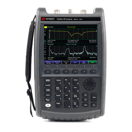
Keysight N9912A User Manual (344 pages)
FieldFox Analyzers
Brand:
Keysight
| Category:
Measuring Instruments
| Size: 3.93 MB
Table of Contents
Safety Notices
2
Table of Contents
5
Overview
15
Options and Features
15
Accessories
17
Fieldfox Manuals, Software, and Supplemental Help
18
Conventions that Are Used in the Manual
18
Safety Notes
19
Preparing for Initial Use of Your New Fieldfox
21
Check the Shipment
21
Meeting Power Requirements for the AC/DC Adapter
21
Install the Lithium-Ion Battery
22
Battery Usage
22
Fieldfox ON/OFF Settings
23
Power Button LED Status
24
Fieldfox High Temperature Protection
24
How to Monitor the Internal Fieldfox Temperature
24
Temperature Control Mode
25
High-Temp Shut down
25
Avoid Overpowering the Fieldfox
25
Take the Fieldfox Tour
27
Front Panel
27
Top Panel
30
Side Panel
30
Screen Tour
32
How to Enter Numeric Values
34
Multiplier Abbreviations
34
Connector Care
35
CAT (Cable and Antenna Test) Mode
37
CAT Mode Settings
39
How to Select CAT Mode
39
Measurement Selection
39
Quick Settings Table
40
Frequency Range
41
Scale Settings
41
Averaging
42
Smoothing
43
Single or Continuous Measure
43
Resolution (Number of Data Points)
44
Sweep Time
44
Output Power
45
Interference Rejection
46
Coupled Frequency
47
Return Loss Measurements
48
How to Measure Return Loss
48
1-Port Cable Loss Measurements
48
How to Make a 1-Port Cable Loss Measurement
49
2-Port Insertion Loss Measurements
50
DTF (Distance to Fault) Measurements
53
How to Make DTF Measurements
54
DTF Measurement Settings
55
DTF Settings Table
55
DTF Measurement (Format)
55
DTF Start and Stop Distance
56
Frequency Mode
56
Coupled Frequency
57
Cable (Correction) Specifications
58
Window Settings
61
DTF Units
61
Calculated DTF Values
62
About Alias Faults
62
NA (Network Analyzer) Mode
65
NA Mode Settings
67
Measurement Selection
67
Parameter Conversion
67
Multi-Trace Configurations
68
Quick Settings
69
Calibration Settings
70
Format
71
Frequency Range
72
Scale Settings
72
Magnitude Offset
73
Electrical Delay
74
Phase Offset
74
Averaging
75
IF Bandwidth
76
Smoothing
76
Single or Continuous Measure
77
Resolution (Number of Data Points)
77
Sweep Time
78
Output Power
78
System Impedance (Z0)
79
Port Extensions
80
Velocity Factor
81
S21Transmission Measurements
81
Big Marker Display States (a and B)
82
Increase Dynamic Range
84
Time Domain - Option 010
85
Overview
87
Time Domain (Transform) Settings
88
Transform Settings Table
88
Frequency Range and Points
88
Stimulus (Mode)
89
Set Frequency Lowpass
89
Start/Stop Time
89
Distance Units
90
Window Layout
90
Transform Window
90
Line Loss and Velocity Factor
91
Data Chain
92
Trace Settings
93
Transform Enable
93
Gate Enable
93
Gating
94
How to Make Time Domain Gating Settings
94
Start, Stop, Center, and Span Gate Times
94
Gating Type
94
Calibration for NA, CAT, and VVM Modes
97
Why and When to Calibrate
98
Definitions
98
Preset Calibration (also Known as Calready)
99
Quickcal
99
O, S, L Cal
101
Normalize
102
Interpolation
103
Cal on ? - Questionable Accuracy
104
Compatible Mode Calibrations
104
Compatible 1-Port and 2-Port Calibrations
104
Save the Calibration
105
Verifying Calibration and Jumper Cable Integrity
106
Verify a Calibration
106
Test the Jumper Cable
106
Calibration Method Summary
107
SA (Spectrum Analyzer) Mode
109
SA Mode Settings
112
How to Select SA Mode
112
Frequency Range
112
Radio Standard
114
Custom Radio Standards
114
Channel Selection
115
Scale and Units
116
External Gain
118
Attenuation Control
118
Preamplifier Control (Opt 235)
119
Check for Compressed Measurements
119
Field Strength Measurements
120
Using the Antenna/Cable Editor
121
Tune & Listen (AM/FM)
124
Independent Source
126
Resolution Bandwidth (Res BW)
128
Video Bandwidth (Video BW)
129
Sweep Type
129
Sweep Acquisition
130
Very Long Sweep Times
131
Zero Span Measurements
131
Triggering
133
Single / Continuous / Restart
135
Points
135
Trace Display States
136
Average Type
137
Average Count
137
Detection Method
138
Display Line
139
Noise Marker
140
Band/Interval Power Marker
141
Frequency Counter at Marker
142
Audio Beep at Marker Power
143
Meas UNCAL Error
143
Old Data Indicator (*)
143
Channel Measurements
145
Radio Standards and Channel Measurements
145
Measurement Preset
145
Averaging
145
Traces
146
Channel Power (CHP)
146
Interference Analyzer (SA Mode) - Option 236
158
Spectrogram and Waterfall Displays
158
Spectrogram Display
158
Common Settings for Waterfall and Spectrogram
159
Record/Playback
163
Channel Power Meter Mode - Option 311
175
CPM Settings
175
How to Select Reflection Mode
175
Frequency/Span/Step
175
Radio Standard
176
Attenuation
176
Power Meter Mode (Option 302)
179
Supported Power Sensors
180
How to Connect the Power Sensor
180
Power Meter Settings
181
How to Select Power Meter Mode
181
Average / Peak
181
Zeroing
181
Frequency
182
Source Control
182
Scale
183
Relative and Offset Power Measurements
184
Display Units
184
Resolution
184
Averaging
185
Single or Continuous Measure
185
Step Detection Mode
186
Limits
186
12 Frequency Offset Using Power Sensor (FOPS) - Option
187
Overview
189
FOPS Settings
191
How to Select Power Meter (USB Sensor)
191
Measurement Selection
191
Sweep Type and Frequency
192
Power Sensor Settling
194
Sweep Settings
194
Amplitude Markers
195
Trace Math
195
Pulse Measurements Mode - Option 330
199
Supported Power Sensors
199
Switching between Pulse Measurement Mode and Power Meter Mode
199
How to Connect the Power Sensor
199
Pulse Measurement Settings
200
How to Select Pulse Measurement Mode
200
Measurement Selection
200
Frequency / Time
200
Zoom Window
201
Scale
202
Averaging
202
Video Bandwidth
203
Single or Continuous Measure
203
Resolution
204
Triggering
204
Marker Settings
207
Amplitude Markers
207
Marker Search
208
Auto Analysis
209
Pulse Top
210
Grid
210
Trace Memory
210
VVM (Vector Voltmeter) Mode - Option 308
215
Overview
215
VVM Mode Settings
216
How to Select VVM Mode
216
Measurement Selection
216
Frequency Selection
216
Display Resolution
217
IF Bandwidth
217
Output Power
217
Averaging
219
Single or Continuous Measure
219
VVM Calibration
220
Zeroing
220
1-Port Cable Trimming Measurements
221
How to Make a 1-Port Cable Trimming Measurement
221
2-Port Transmission Measurements
223
How to Make a 2-Port Transmission Measurement
223
Channel Scanner (SA Only and Option 312)
225
Using Channel Scanner
225
How to Set up Channel Scanner
226
How to Define a Channel and Use Channel Scanner
228
Data Analysis Features
242
All about Markers
242
How to Create Markers
242
How to Move a Marker after It Is Created
242
About Delta Markers
243
Marker Table
244
Coupled Markers (NA Mode)
245
Marker Colors
246
Marker Trace (CAT and NA Modes)
246
Marker Trace (SA Mode)
246
Marker Format
247
Searching with Markers
247
What Is a 'Peak
250
Marker Functions
252
SA Marker Functions
253
All about Limit Lines
254
How to Create Fixed Limit Lines
254
Relative Limit Lines
255
Build from Trace
256
Limit Options
257
How to Save and Recall Limits
257
All about Trace Math
259
How to Display Data and Memory Traces
259
How to Perform Trace Math
259
About Math Operations
260
File Management
261
Saving and Recalling Files
262
Save Files
262
Recall Files
264
Set File Type and Select Device
265
Manage Files
267
Manage Folders
268
Edit Keywords
269
Prefixes for Filenames
270
Printing
271
How to Print the Current Screen or a Saved File
271
18 System Settings
273
Run/Hold
274
How to Perform a Single Sweep While in Hold
274
Preset
275
How to Preset the Fieldfox
275
User Preset
275
How to Set User Preset
276
How to Recall User Preset
276
Volume Control
276
How to Set Fieldfox Volume Control
277
Display Settings
277
Display Brightness
277
Display Colors
277
Trace Width
278
Title
278
Edit Keywords
279
Full Screen Mode
279
Preferences
279
Quick Settings Table
279
Save and Reset Preferences
280
Language
281
Startup Mode
281
Battery Saver
282
File Folders
282
System Configuration
283
Options (Licensing)
283
Gps
284
Frequency Reference Source
287
Security Level
288
Date and Time, Format, and Time Zone Settings
288
LAN Settings
290
Power on
291
Fieldfox Package Installer (N9912A Units with Serial Number Prefixes ≥5607 Only)
292
Service Diagnostics
294
System Information
294
Using the Mini-USB Port to Send SCPI Commands and Queries (N9912A Units with Serial Number Prefixes ≥5607 Only)
297
Mini-USB Connection to PC with IO Libraries
297
20 Working with the Lithium-Ion Battery
299
Viewing the Battery Charge Status
299
Service Diagnostics-Battery Screen
300
Built-In Battery Gauge
300
Charging the Battery
301
Internal Charging with the AC/DC Adapter
301
Using the External Battery Charger (N9910X-872)
303
Reconditioning Battery
304
Battery Care
304
Maximizing Battery Life
304
Lithium-Ion Battery Disposal
305
21 Safety Considerations
307
For the Fieldfox
308
For the AC/DC Adapter
310
For the External Battery Charger (N9910X-872)
312
For the Battery
312
Battery Protective Functions
313
Active Protection
313
Passive Protection
314
Batteries: Safe Handling and Disposal
315
Environmental Requirements
315
Electrical Requirements
315
Electrostatic Discharge (ESD) Precautions
315
Fieldfox Markings
317
Battery Markings
318
Packaging Markings
319
AC/DC Adapter Markings
319
Certification and Compliance Statements
320
Certification
320
Manufacturer's Declaration
320
Declaration of Conformity
320
Emc
321
Safety
321
South Korean Class B EMC Declaration
321
Acoustic Statement (European Machinery Directive)
321
A:.connector Care Review
323
B:.specifications/Data Sheet
325
C:.instrument Calibration
327
How Often Should Calibrate My Instrument
327
How Do I Get an Instrument Calibration
327
What Are My Choices of Instrument Calibration
328
D:.korean Battery Safety Translation
329
Advertisement
Keysight N9912A User Manual (207 pages)
FieldFox Analyzer
Brand:
Keysight
| Category:
Measuring Instruments
| Size: 3.53 MB
Table of Contents
Table of Contents
4
A.07.75 Firmware Release Updates
7
Overview
8
Options and Features
8
Accessories
9
Fieldfox Manuals, Software, and Supplemental Help
10
Preparing for Initial Use of Your New Fieldfox
11
Check the Shipment
11
Meeting Power Requirements for the AC/DC Adapter
11
Install the Lithium-Ion Battery
12
See also Battery Usage
12
Fieldfox ON/OFF Settings
13
Fieldfox High-Temperature Protection
13
Fieldfox Internal Temperatures
13
Avoid Overpowering the Fieldfox
14
Take the Fieldfox Tour
15
How to Enter Numeric Values
19
Cat (Cable and Antenna Test) Mode
20
CAT Mode Settings
21
Measurement Selection
21
Frequency Range
22
Quick Settings
22
Averaging
23
Scale Settings
23
Resolution
24
Output Power
25
Sweep Time
25
Return Loss Measurements
26
1 Port Cable Loss Measurements
27
2 Port Insertion Loss Measurements
28
DTF (Distance to Fault) Measurements
30
DTF Measurement Settings
31
NA (Network Analyzer) Mode
38
NA Mode Settings
38
In this Chapter
38
Time Domain - Option 010
52
Time Domain (Transform) Settings
53
Transform Settings Table
53
Frequency Range and Points
54
Set Frequency Lowpass
54
Start/Stop Time
54
Stimulus (Mode)
54
Distance Units
55
Transform Window
55
Window Layout
55
Data Chain
56
Line Loss and Velocity Factor
56
Trace Settings
56
Gating
57
Gating Enable
57
Transform Enable
57
Gating Type
58
Start, Stop, Center, and Span Gate Times
58
Calibration for Cat, Na, and VVM Modes
60
Definitions
60
Why and When to Calibrate
60
Preset Calibration
61
Quickcal
61
O,S,L Calibration
62
Normalize
63
Compatible 1-Port and 2-Port Calibrations
65
Compatible Mode Calibrations
65
Save a Calibration
65
Verify Calibration
65
Verifying Calibration and Jumper Cable Integrity
65
Calibration Method Summary
66
Sa (Spectrum Analyzer) Mode
67
Frequency Range
68
Radio Standard
70
Channel Selection
71
Scale and Units
72
Attenuation and Preamp Control
73
External Gain
73
Check for Compressed Measurements
74
Field Strength Measurements
75
Tune and Listen
78
Resolution Bandwidth
81
Video Bandwidth
81
Sweep Acquisition
82
Sweep Type
82
Very Long Sweep Times
83
Zero Span Measurements
84
Triggering
85
Single/Continuous/Restart
86
Points
87
Trace Display States
87
Average Count
88
Average Type
88
Detection Method
89
Display Line
90
Noise Marker
90
Band/Interval Power Marker
91
Audio Beep at Marker Power
92
Frequency Counter at Marker
92
Channel Measurements
93
Channel Power
94
Occupied Bandwidth
96
Adjacent Channel Power Ratio
97
Interference Analyzer (Sa Mode) - Option 236
102
Interference Analyzer (Opt 236) Spectrogram Display
102
Spectrogram and Waterfall Displays
102
Spectrogram Display
102
Waterfall Display
105
Record / Playback
106
Record Playback
106
About Sessions
106
About State and User Tags
107
How to Record a Session
108
How to Playback a Session
109
Recording Configuration
109
Playback Configuration
112
Manage Sessions
112
Record Playback Example
113
Channel Power Meter Mode - Option 311
114
Radio Standard
115
Set Frequency/Span
115
Attenuation
116
See also
117
Supported Power Sensors
117
How to Connect the Power Sensor
118
Average/Peak
118
Zeroing
118
Learn more about These Settings: Set Scale
119
Set Frequency
119
Set Source Control
119
Set Scale
119
Set Relative and Offset Power
120
Set Averaging
121
Set Display Units
121
Set Limits
122
Step Detection Mode
122
Single/Continuous
122
Frequency Offset Using Power Sensor (Fops) - Option 208
123
See also
123
Overview
124
Measurement Selection
125
Sweep Type and Frequency
125
Power Sensor Settling
127
Sweep Settings
127
Amplitude Markers
128
Pulse Measurements Mode - Option 330
129
Measurement Selection
130
Supported Power Sensors
130
Frequency / Time
131
Zoom Window
131
Scale
132
Averaging
133
Single or Continuous Measure
133
Video Bandwidth
133
Resolution
134
Triggering
134
Amplitude Markers
136
Marker Settings
136
Pulse Timing Diagram
136
Auto Analysis
137
Marker Search
137
Grid
138
Pulse Top
138
Trace Memory
139
VVM (Vector Voltmeter) Mode - Option 308
140
Measurement Selection
141
Overview
141
Display Resolution
142
Frequency Selection
142
IF Bandwidth
142
Output Power
142
Averaging
143
Single/Continuous
143
1 Port Cable Trimming Measurement
144
VVM Calibration
144
Zeroing
144
2 Port Transmission Measurement
146
Data Analysis Features
147
All about Markers
147
About Delta Markers
148
Marker Table
149
Coupled Markers
149
Marker Colors
150
Marker Trace
150
Marker Format
151
Searching with Markers
151
What Is a 'Peak
154
Marker Functions
155
SA Noise Marker
155
Optional Settings Markers
147
All about Limit Lines
156
Relative Limit Lines
157
Build from Trace
158
Limit Options
158
Limit Lines
156
SA Band Power Marker
156
SA Frequency Counter at Marker
156
All about Trace Math
159
About Math Operations
160
Trace Math
159
How to Save and Recall Limits
159
File Management
162
Save Files
162
Save Measurement Settings and Results
162
Recall Files
164
Set File Type and Device
164
Manage Files
166
Manage Folders
166
Edit Keywords
167
Prefixes for Filenames
168
Printing
168
System Settings
170
Run/Hold
170
Preset
171
User Preset
171
Volume Control
171
Display Settings
172
Brightness
173
Colors
173
Trace Width
173
Title
174
Edit Keywords
174
Full Screen Mode
174
Preferences
174
Quick Settings Table
174
Save and Reset Preferences
175
Language
176
Startup Mode
176
Battery Saver
176
System Configuration Options (Licensing)
177
Gps
178
Frequency Reference Source
180
Security Level
180
Date and Time Settings
181
LAN Settings
182
See also Erase User Data
183
Power on
183
Service Diagnostics
183
Erase User Data
184
Working with the Lithium-Ion Battery
185
Charging the Battery
185
Viewing Battery Charge Status
185
Reconditioning the Battery
188
Battery Care
189
Maximizing Battery Life
189
Battery Disposal
190
Keysight N9912A Service Manual (147 pages)
RF Analyzer
Brand:
Keysight
| Category:
Measuring Instruments
| Size: 4.62 MB
Table of Contents
Table of Contents
5
Safety and Regulatory Information
9
Information in this Chapter
9
Chapter One At-A-Glance
9
Safety Symbols
10
General Safety Considerations
11
Safety Earth Ground
11
Before Applying Power
11
Servicing
11
Electrostatic Discharge Protection
13
Regulatory Information
15
Instrument Markings
15
Battery Disposal
16
General Product Information
17
Information in this Chapter
17
Chapter Two At-A-Glance
17
Maintenance
18
Physical Maintenance
18
Electrical Maintenance
18
Analyzer Options
19
Option 110, Transmission Measurement
19
Option 111, Quickcal
19
Option 230, 4 Ghz Spectrum Analyzer
19
Option 231, 6 Ghz Spectrum Analyzer
19
Option 235, Preamplifier for Spectrum Analyzer
19
Option 302, External USB Power Sensor Support
19
Option 303, Network Analyzer Capability
19
Keysight Support, Services, and Assistance
20
Service and Support Options
20
Calibration Options
20
Contacting Keysight
21
Shipping Your Analyzer to Keysight for Service or Repair
21
Tests and Adjustments
23
Information in this Chapter
23
Chapter Three At-A-Glance
23
Before You Begin
25
Allow the Analyzer to Warm up
25
Review the Principles of Connector Care
25
Service Test Equipment
27
Before Returning an Instrument to a Customer
28
Operational Check
29
Performance Tests (Keysight N7841A Software Package)
30
General Tests
30
Spectrum Analyzer Specific Tests
30
Adjustments (Keysight N7841A Software Package)
31
General Adjustments
31
Spectrum Analyzer Specific Adjustments
31
Troubleshooting
33
Information in this Chapter
33
Chapter Four At-A-Glance
33
Protect against Electrostatic Discharge (ESD)
34
Assembly Replacement Sequence
35
Getting Started with Troubleshooting
36
Check the Basics
36
Troubleshooting Organization
36
Power up Troubleshooting
38
Front Panel Group Troubleshooting
39
Measurement Group Troubleshooting
40
Theory of Operation
41
Information in this Chapter
41
Chapter Five At-A-Glance
41
Analyzer System Operation
42
Functional Groups of the Analyzer
42
Front Panel Group
44
A3 Front Panel Interface Board
44
A2 LCD Assembly
45
Measurement Group
46
A4 RF Board
46
A5 System Board
50
A6 SOM Board
55
Main Battery
55
Grounding and Power
56
Grounding
56
Voltages and Power Supplies
56
Power Control and Management
57
Battery Related Information
58
Operation in Modes
60
CAT and NA Modes
61
SA Mode
64
Power Meter Mode
65
Temperature Related Information
66
User Calibration in CAT and NA Modes
67
One Port Calibration
67
Two Port Calibration
68
Quickcal
68
Firmware Related Information
69
General Description
69
User Accessible Files
69
Operational Files
69
Erase User Data Utility
70
Error Log
70
Firmware Upgrades
70
LAN Interface
71
Replaceable Parts
73
Information in this Chapter
73
Chapter Six At-A-Glance
73
Ordering Information
74
Assembly Replacement Procedure
75
Replaceable Parts Listings
76
Entire Analyzer
76
Front Panel Group
76
Measurement Group
76
Case Group
76
Miscellaneous Parts
84
Repair and Replacement Procedures
87
Information in this Chapter
87
Chapter Seven At-A-Glance
87
Personal Safety Warnings
88
Safety Earth Ground
88
Electrostatic Discharge (ESD) Protection
89
Assembly Replacement Sequence
90
Removal and Replacement Procedures
91
Removing and Replacing the Main Battery
92
Removing and Replacing the Case Group Parts
93
Removing and Replacing the Front Panel Group Assemblies
107
Removing and Replacing the Measurement Group Assemblies
115
Post-Repair Procedures
130
Manual Checks and Procedures
130
Processor Upgrade Procedures
132
General Purpose Maintenance and Service Procedures
135
Information in this Chapter
135
Chapter Eight At-A-Glance
135
Service Related User Operations
136
To View Currently Installed Options
136
To View the Current Firmware Revision, Etc
136
To View the Error Log
136
To View Temperature Readings
136
Erase User Data Utility
137
Options
138
To View Currently Installed Options
138
Re-Installing Options
138
Firmware Upgrades
140
To Check the Current Firmware Revision
140
Miscellaneous Service and Maintenance
141
Cleaning the Display
141
Battery Maintenance
141
Advertisement
Keysight N9912A Service Manual (135 pages)
rf analyzer
Brand:
Keysight
| Category:
Analytical Instruments
| Size: 5.49 MB
Table of Contents
Table of Contents
7
1 Safety and Regulatory Information
11
Information in this Chapter
12
Chapter One At-A-Glance
12
Section Title
12
Summary of Content
12
Start Page
12
Safety Symbols
13
General Safety Considerations
13
Safety Earth Ground
13
Before Applying Power
14
Servicing
14
Electrostatic Discharge Protection
15
Regulatory Information
16
Instrument Markings
16
Battery Disposal
17
2 General Product Information
19
Information in this Chapter
20
Chapter Two At-A-Glance
20
Maintenance
21
Physical Maintenance
21
Electrical Maintenance
21
Analyzer Options
21
Option 110, Transmission Measurement
21
Option 111, Quickcal
21
Option 230, 4 Ghz Spectrum Analyzer
21
Option 231, 6 Ghz Spectrum Analyzer
21
Option 235, Preamplifier for Spectrum Analyzer
21
Option 302, External USB Power Sensor Support
22
Option 303, Network Analyzer Capability
22
Keysight Support, Services, and Assistance
22
Service and Support Options
22
Calibration Options
22
Contacting Keysight
23
Shipping Your Analyzer to Keysight for Service or Repair
23
3 Tests and Adjustments
25
Information in this Chapter
26
Chapter Three At-A-Glance
26
Before You Begin
27
Protect against Electrostatic Discharge (ESD)
27
Allow the Analyzer to Warm up
27
Review the Principles of Connector Care
28
N9912A Analyzer
29
Service Test Equipment
29
Before Returning an Instrument to a Customer
30
Operational Check
30
Adjustments
31
Performance Tests
31
Performance Tests (Keysight N7841A Software Package)
31
General Tests
31
Spectrum Analyzer Specific Tests
31
Adjustments (Keysight N7841A Software Package)
32
General Adjustments
32
Spectrum Analyzer Specific Adjustments
32
4 Troubleshooting
33
Information in this Chapter
34
Chapter Four At-A-Glance
34
Protect against Electrostatic Discharge (ESD)
35
Assembly Replacement Sequence
35
Getting Started with Troubleshooting
36
Check the Basics
36
Troubleshooting Organization
37
Power up Troubleshooting
38
Front Panel Group Troubleshooting
39
Measurement Group Troubleshooting
40
5 Theory of Operation
41
Information in this Chapter
42
Chapter Five At-A-Glance
42
Analyzer System Operation
43
Functional Groups of the Analyzer
43
Front Panel Group
45
A3 Front Panel Interface Board
45
A2 LCD Assembly
46
Measurement Group
47
A4 RF Board
47
A5 System Board
52
A6 SOM Board
56
Main Battery
56
Grounding and Power
57
Grounding
57
Voltages and Power Supplies
57
Power Control and Management
57
Battery Related Information
58
Operation in Modes
60
CAT and NA Modes
61
SA Mode
63
Power Meter Mode
63
Temperature Related Information
64
User Calibration in CAT and NA Modes
65
One Port Calibration
65
Two Port Calibration
66
Quickcal
66
Firmware Related Information
67
General Description
67
User Accessible Files
67
Operational Files
67
Erase User Data Utility
67
Error Log
67
Firmware Upgrades
68
LAN Interface
69
6 Replaceable Parts
71
Information in this Chapter
72
Chapter Six At-A-Glance
72
Ordering Information
73
Assembly Replacement Procedure
74
Replaceable Parts Listings
75
Entire Analyzer
75
Front Panel Group
76
Measurement Group
78
Case Group
81
Miscellaneous Parts
84
7 Repair and Replacement Procedures
85
Information in this Chapter
86
Chapter Seven At-A-Glance
86
Personal Safety Warnings
87
Safety Earth Ground
87
Electrostatic Discharge (ESD) Protection
87
Assembly Replacement Sequence
88
Removal and Replacement Procedures
88
Removing and Replacing the Main Battery
89
Removing and Replacing the Case Group Parts
90
Removing and Replacing the Front Panel Group Assemblies
102
Removing and Replacing the Measurement Group Assemblies
109
Post-Repair Procedures
121
Manual Checks and Procedures
122
8 General Purpose Maintenance and Service Procedures
123
Information in this Chapter
124
Chapter Eight At-A-Glance
124
Service Related User Operations
125
To View Currently Installed Options
125
To View the Current Firmware Revision, Etc
125
To View the Error Log
125
To View Temperature Readings
125
Erase User Data Utility
126
Options
127
To View Currently Installed Options
127
Re-Installing Options
127
Firmware Upgrades
128
To Check the Current Firmware Revision
128
Miscellaneous Service and Maintenance
129
Cleaning the Display
129
Battery Maintenance
129
Advertisement
Related Products
Keysight N9913B
Keysight N9914B
Keysight N9915B
Keysight N9916B
Keysight N9917B
Keysight N9918B
Keysight N9933B
Keysight N9934B
Keysight N9935B
Keysight N9937B
Keysight Categories
Measuring Instruments
Test Equipment
Multimeter
Control Unit
Portable Generator
More Keysight Manuals
Login
Sign In
OR
Sign in with Facebook
Sign in with Google
Upload manual
Upload from disk
Upload from URL